377

Satellite NetworkingPrinciples and Protocols
Zhili SunUniversity of Surrey, UK


Satellite Networking


Satellite NetworkingPrinciples and Protocols
Zhili SunUniversity of Surrey, UK

Copyright © 2005 John Wiley & Sons Ltd, The Atrium, Southern Gate, Chichester,West Sussex PO19 8SQ, England
Telephone (+44) 1243 779777
Email (for orders and customer service enquiries): [email protected] our Home Page on www.wiley.com
All Rights Reserved. No part of this publication may be reproduced, stored in a retrieval system ortransmitted in any form or by any means, electronic, mechanical, photocopying, recording,scanning or otherwise, except under the terms of the Copyright, Designs and Patents Act 1988 orunder the terms of a licence issued by the Copyright Licensing Agency Ltd, 90 Tottenham CourtRoad, London W1T 4LP, UK, without the permission in writing of the Publisher. Requests to thePublisher should be addressed to the Permissions Department, John Wiley & Sons Ltd, The Atrium,Southern Gate, Chichester, West Sussex PO19 8SQ, England, or emailed to [email protected], orfaxed to (+44) 1243 770620.
Designations used by companies to distinguish their products are often claimed as trademarks.All brand names and product names used in this book are trade names, service marks, trademarks orregistered trademarks of their respective owners. The Publisher is not associated with anyproduct or vendor mentioned in this book.
This publication is designed to provide accurate and authoritative information in regard to the subjectmatter covered. It is sold on the understanding that the Publisher is not engaged in renderingprofessional services. If professional advice or other expert assistance is required, the services of acompetent professional should be sought.
Other Wiley Editorial Offices
John Wiley & Sons Inc., 111 River Street, Hoboken, NJ 07030, USA
Jossey-Bass, 989 Market Street, San Francisco, CA 94103-1741, USA
Wiley-VCH Verlag GmbH, Boschstr. 12, D-69469 Weinheim, Germany
John Wiley & Sons Australia Ltd, 42 McDougall Street, Milton, Queensland 4064, Australia
John Wiley & Sons (Asia) Pte Ltd, 2 Clementi Loop #02-01, Jin Xing Distripark, Singapore 129809
John Wiley & Sons Canada Ltd, 22 Worcester Road, Etobicoke, Ontario, Canada M9W 1L1
Wiley also publishes its books in a variety of electronic formats. Some content that appearsin print may not be available in electronic books.
Library of Congress Cataloging in Publication Data
Sun, Zhili.Satellite networking principles and protocols / Zhili Sun.p. cm.
Includes bibliographical references.ISBN-10: 0-470-87027-3ISBN-13: 978-0-470-87027-31. Artificial satellites in telecommunication. 2. Computer network protocols.3. Internetworking (Telecommunication) I. Title.TK5104.S78 2005621.382′5′028546—dc22
2005012260
British Library Cataloguing in Publication Data
A catalogue record for this book is available from the British Library
ISBN-13 978-0-470-87027-3 (HB)ISBN-10 0-470-87027-3 (HB)
Typeset in 10/12pt Times by Integra Software Services Pvt. Ltd, Pondicherry, India.Printed and bound in Great Britain by Antony Rowe Ltd, Chippenham, Wiltshire.This book is printed on acid-free paper responsibly manufactured from sustainable forestryin which at least two trees are planted for each one used for paper production.

This book is dedicated to the memory of my grandparents
To my parents
To my wife

Contents
List of Tables xix
List of Figures xxi
Preface xxvii
Acknowledgements xxxi
1 Introduction 11.1 Applications and services of satellite networks 1
1.1.1 Roles of satellite networks 21.1.2 Network software and hardware 41.1.3 Satellite network interfaces 41.1.4 Network services 51.1.5 Applications 5
1.2 ITU-R definitions of satellite services 51.2.1 Fixed satellite service (FSS) 51.2.2 Mobile satellite service (MSS) 61.2.3 Broadcasting satellite service (BSS) 61.2.4 Other satellite services 6
1.3 ITU-T definitions of network services 61.3.1 Interactive services 61.3.2 Distribution services 7
1.4 Internet services and applications 81.4.1 World wide web (WWW) 81.4.2 File transfer protocol (FTP) 91.4.3 Telnet 91.4.4 Electronic mail (email) 91.4.5 Multicast and content distribution 101.4.6 Voice over internet protocol (VoIP) 101.4.7 Domain name system (DNS) 10
1.5 Circuit-switching network 111.5.1 Connection set up 121.5.2 Signalling 12

viii Contents
1.5.3 Transmission multiplexing hierarchy based on FDM 131.5.4 Transmission multiplexing hierarchy based on TDM 131.5.5 Space switching and time switching 151.5.6 Coding gain of forward error correction (FEC) 16
1.6 Packet-switching networks 161.6.1 Connection-oriented approach 171.6.2 Connectionless approach 181.6.3 Relationship between circuit switching and packet switching 191.6.4 Impacts of packet on network designs 201.6.5 Packet header and payload 201.6.6 Complexity and heterogeneous networks 201.6.7 Performance of packet transmissions 211.6.8 Impact of bit level errors on packet level 21
1.7 OSI/ISO reference model 221.7.1 Protocol terminology 221.7.2 Layering principle 221.7.3 Functions of the seven layers 231.7.4 Fading of the OSI/ISO reference model 24
1.8 The ATM protocol reference model 241.8.1 Narrowband ISDN (N-ISDN) 241.8.2 Broadband ISDN (B-ISDN) 241.8.3 ATM technology 251.8.4 The reference model 251.8.5 Problems: lack of available services and applications 26
1.9 Internet protocols reference model 261.9.1 Network layer: IP protocol 271.9.2 Network technologies 271.9.3 Transport layer: TCP and UDP 271.9.4 Application layer 271.9.5 Problems: no QoS and no control on resources 27
1.10 Satellite network 281.10.1 Access network 281.10.2 Transit network 281.10.3 Broadcast network 281.10.4 Space segment 281.10.5 Ground segment 301.10.6 Satellite orbits 301.10.7 Satellite transmission frequency bands 31
1.11 Characteristics of satellite networks 321.11.1 Propagation delay 331.11.2 Propagation loss and power limited 331.11.3 Orbit space and bandwidth limited for coverage 341.11.4 Operational complexity for LEO 34
1.12 Channel capacity of digital transmissions 341.12.1 The Nyquist formula for noiseless channels 341.12.2 The Shannon theorem for noise channels 341.12.3 Channel capacity boundary 351.12.4 The Shannon power limit (−16dB) 361.12.5 Shannon bandwidth efficiency for large Eb/N0 36

Contents ix
1.13 Internetworking with terrestrial networks 371.13.1 Repeaters at the physical layer 371.13.2 Bridges at link layer 371.13.3 Switches at the physical, link and network layers 371.13.4 Routers for interconnecting heterogeneous networks 381.13.5 Protocol translation, stacking and tunnelling 381.13.6 Quality of service (QoS) 391.13.7 End-user QoS class and requirements 391.13.8 Network performance 401.13.9 QoS and NP for satellite networking 40
1.14 Digital video broadcasting (DVB) 421.14.1 The DVB standards 421.14.2 DVB-S satellite delivery 431.14.3 MPEG-2 baseband processing 441.14.4 Transport stream (TS) 441.14.5 Service objectives 451.14.6 Satellite channel adaptation 451.14.7 DVB return channel over satellite (DVB-RCS) 461.14.8 TCP/IP over DVB 47
1.15 Historical development of computer and data networks 471.15.1 The dawn of the computer and data communications age 471.15.2 Development of local area networks (LANs) 471.15.3 Development of WANs and ISO/OSI 481.15.4 The birth of the Internet 481.15.5 Integration of telephony and data networks 481.15.6 Development of broadband integrated networks 481.15.7 The killer application WWW and Internet evolutions 49
1.16 Historical development of satellite communications 491.16.1 Start of satellite and space eras 491.16.2 Early satellite communications: TV and telephony 491.16.3 Development of satellite digital transmission 501.16.4 Development of direct-to-home (DTH) broadcast 501.16.5 Development of satellite maritime communications 501.16.6 Satellite communications in regions and countries 501.16.7 Satellite broadband networks and mobile networks 501.16.8 Internet over satellite networks 50
1.17 Convergence of network technologies and protocols 511.17.1 Convergence of services and applications in user terminals 511.17.2 Convergence of network technologies 521.17.3 Convergence of network protocols 521.17.4 Satellite network evolution 53
Further reading 53Exercises 53
2 Satellite Orbits and Networking Concepts 552.1 Laws of physics 56
2.1.1 Kepler’s three laws 562.1.2 Newton’s three laws of motion and the universal law of gravity 562.1.3 Kepler’s first law: satellite orbits 572.1.4 Kepler’s second law: area swept by a satellite vector 59

x Contents
2.1.5 Kepler’s third law: orbit period 602.1.6 Satellite velocity 60
2.2 Satellite orbit parameters 612.2.1 Semi-major axis (a) 612.2.2 Eccentricity (e) 612.2.3 Inclination of orbit (i) 622.2.4 Right ascension of the node () and argument of perigee () 63
2.3 Useful orbits 632.3.1 Geosynchronous earth orbits 632.3.2 Geostationary earth orbits (GEOs) 642.3.3 High elliptical orbits (HEOs) 642.3.4 Notations of low earth orbit (LEO) satellite constellations 652.3.5 Orbital perturbations 662.3.6 Satellite altitude and coverage 662.3.7 Antenna gain and beam-width angle 672.3.8 Coverage calculations 672.3.9 Distance and propagation delay from earth station to satellite 68
2.4 Satellite link characteristics and modulations for transmissions 692.4.1 Satellite link characteristics 712.4.2 Modulation techniques 712.4.3 Phase shift keying (PSK) schemes for satellite transmissions 722.4.4 Binary phase shift keying (BPSK) 732.4.5 Quadrature PSK (QPSK) 732.4.6 Gaussian-filtered minimum shift keying (GMSK) 742.4.7 Bit error rate (BER): the quality parameter of modulation schemes 752.4.8 Satellite networking in the physical layer 75
2.5 Forward error correction (FEC) 772.5.1 Linear block codes 782.5.2 Cyclic codes 782.5.3 Trellis coding and convolutional codes 792.5.4 Concatenated codes 792.5.5 Turbo codes 802.5.6 Performance of FEC 81
2.6 Multiple access techniques 812.6.1 Frequency division multiple access (FDMA) 832.6.2 Time division multiple access (TDMA) 832.6.3 Code division multiple access (CDMA) 842.6.4 Comparison of FDMA, TDMA and CDMA 84
2.7 Bandwidth allocation 842.7.1 Fixed assignment access 852.7.2 Demand assignment 852.7.3 Random access 86
2.8 Satellite networking issues 862.8.1 Single hop satellite connections 862.8.2 Multi-hop satellite connections 862.8.3 Inter-satellite links (ISL) 882.8.4 Handovers 892.8.5 Satellite intra-beam and inter-beam handovers 902.8.6 Earth fixed coverage vs. satellite fixed coverage 912.8.7 Routing within constellation of satellites network 92
Contents xi
2.8.8 Internetworking 922.8.9 Satellite availability and diversity 93
Further reading 94Exercises 94
3 ATM and Internet Protocols 973.1 ATM protocol and fundamental concepts 97
3.1.1 Packetisation delay 993.1.2 Queuing delay 993.1.3 Compromise solution between North America and Europe 100
3.2 ATM layer 1013.2.1 The GFC field 1013.2.2 The VPI and VCI fields 1013.2.3 The CLP field 1033.2.4 The PT field 1043.2.5 The HEC field 104
3.3 ATM adaptation layer (AAL) 1043.3.1 AAL1 for class A 1053.3.2 AAL2 for class B 1073.3.3 AAL3/4 for classes C and D 1073.3.4 AAL5 for Internet protocol 107
3.4 The physical layer 1093.4.1 The physical medium (PM) sublayers 1093.4.2 The transmission convergence (TC) sublayer 1093.4.3 ATM cell transmissions 1103.4.4 Target solution for ATM transmission 1103.4.5 ATM over synchronous digital hierarchy (SDH) 1103.4.6 ATM over DS1 1123.4.7 ATM over E1 113
3.5 ATM interfaces and ATM networking 1133.5.1 User–network access 1133.5.2 Network node interconnections 1143.5.3 ATM DXI 1153.5.4 B-ICI 1163.5.5 Permanent virtual connections vs. switched virtual connections 1163.5.6 ATM signalling 1173.5.7 ATM addressing 1173.5.8 Address registration 118
3.6 Network traffic, QoS and performance issues 1193.6.1 Traffic descriptors 1203.6.2 Quality of service (QoS) parameters 1203.6.3 Performance issues 120
3.7 Network resource management 1213.7.1 Connection admission control (CAC) 1223.7.2 UPC and NPC 1223.7.3 Priority control and congestion control 1223.7.4 Traffic shaping 1233.7.5 Generic cell rate algorithm (GCRA) 1233.7.6 Leaky bucket algorithm (LBA) 1233.7.7 Virtual scheduling algorithm (VSA) 126

xii Contents
3.8 Internet protocols 1273.8.1 Internet networking basics 1273.8.2 Protocol hierarchies 1283.8.3 Connectionless network layer 1283.8.4 The IP packet format 1283.8.5 IP address 1303.8.6 Mapping between Internet and physical network addresses 1313.8.7 ARP and RARP 1323.8.8 Internet routing protocols 1323.8.9 The interior gateway routing protocol (IGRP) 1323.8.10 The exterior gateway routing protocol (EGRP) 133
3.9 Transport layer protocols: TCP and UDP 1333.9.1 Transmission control protocol (TCP) 1333.9.2 The TCP segment header format 1343.9.3 Connection set up and data transmission 1353.9.4 Congestion and flow control 1363.9.5 User datagram protocol (UDP) 137
3.10 IP and ATM internetworking 1383.10.1 LAN emulation (LANE) 1393.10.2 LANE components 1403.10.3 LANE entity communications 1403.10.4 Classical IP over ATM 1413.10.5 Packet encapsulation 1413.10.6 IP and ATM address resolution 142
Further reading 143Exercises 144
4 Satellite Internetworking with Terrestrial Networks 1454.1 Networking concepts 1454.2 Networking terminology 147
4.2.1 Private network 1474.2.2 Public network 1474.2.3 Quality aspects of telephony services 1484.2.4 IP based network 148
4.3 Network elements and connections 1494.3.1 Network terminals 1494.3.2 Network nodes 1504.3.3 Network connections 1504.3.4 End-to-end connections 1514.3.5 Reference configurations 151
4.4 Network traffic and signalling 1524.4.1 User traffic and network services 1524.4.2 Signalling systems and signalling traffic 1544.4.3 In-band signalling 1544.4.4 Out-of-band signalling 1554.4.5 Associated and disassociated channel signalling 1564.4.6 ITU-T signalling system No. 7 (ITU-T SS7) 1564.4.7 Network management 1584.4.8 Network operation systems and mediation functions 158

Contents xiii
4.5 Access and transit transmission networks 1604.5.1 Analogue telephony networks 1604.5.2 Telephony network traffic engineering concept 1614.5.3 Access to satellite networks in the frequency domain 1624.5.4 On-board circuit switching 162
4.6 Digital telephony networks 1634.6.1 Digital multiplexing hierarchy 1634.6.2 Satellite digital transmission and on-board switching 1644.6.3 Plesiochronous digital hierarchy (PDH) 1654.6.4 Limitations of the PDH 165
4.7 Synchronous digital hierarchy (SDH) 1664.7.1 Development of SDH 1674.7.2 The SDH standards 1674.7.3 Mapping from PDH to SDH 1684.7.4 The benefits of SDH 1694.7.5 Synchronous operation 1694.7.6 Synchronous optical network (SONET) 1714.7.7 SDH over satellite – the Intelsat scenarios 171
4.8 Integrated services digital networks (ISDN) 1734.8.1 Basic rate interface (BRI) 1734.8.2 Primary rate interface (PRI) 1744.8.3 ISDN physical layer (layer 1) 1754.8.4 ISDN link layer (layer 2) 1764.8.5 ISDN network layer (layer 3) 176
4.9 ISDN over satellite 1774.9.1 ITU-T ISDN hypothetical reference connection (IRX) 1774.9.2 ITU-R hypothetical reference digital path (HRDP) for satellite 1784.9.3 Performance objectives 1794.9.4 Satellite network to ISDN interconnection scenarios 1794.9.5 Routing plan 180
4.10 Interworking with heterogeneous networks 1834.10.1 Services 1844.10.2 Addressing 1844.10.3 Routing 1844.10.4 Evolution 185
Further reading 185Exercises 186
5 ATM over Satellite Networks 1875.1 Background 187
5.1.1 Networking issues 1885.1.2 Satellite services in the B-ISDN networking environment 188
5.2 Design issues of satellite ATM systems 1905.2.1 Propagation delay 1905.2.2 Attenuation and constraints 191
5.3 The GEO satellite ATM networking architecture 1925.3.1 The ground segment 1925.3.2 The space segment 1935.3.3 Satellite bandwidth resource management 1945.3.4 Connection admission control (CAC) 195

xiv Contents
5.3.5 Network policing functions 1955.3.6 Reactive congestion control 196
5.4 Advanced satellite ATM networks 1965.4.1 Radio access layer 1975.4.2 On-board processing (OBP) characteristics 1975.4.3 The ATM on-board switch 1985.4.4 Multibeam satellites 1995.4.5 LEO/MEO satellite constellations 2015.4.6 Inter-satellite links (ISL) 2015.4.7 Mobile ATM 2025.4.8 Use of higher frequency spectrum 202
5.5 ATM performance 2035.5.1 Layered model of performance for B-ISDN 2035.5.2 ATM performance parameters 2035.5.3 Impact of satellite burst errors on the ATM layer 2055.5.4 Impact of burst errors on AAL protocols 2075.5.5 Error control mechanisms 2085.5.6 Enhancement techniques for satellite ATM networks 209
5.6 Evolution of ATM satellite systems 210Further reading 212Exercises 212
6 Internet Protocol (IP) over Satellite Networks 2136.1 Different viewpoints of satellite networking 213
6.1.1 Protocol-centric viewpoint of satellite IP network 2146.1.2 Satellite-centric viewpoint of global networks and the Internet 2156.1.3 Network-centric viewpoint of satellite networks 216
6.2 IP packet encapsulation 2176.2.1 Basic concepts 2176.2.2 High-level data link control (HDLC) protocol 2176.2.3 Point-to-point protocol (PPP) 2186.2.4 Media access control 2196.2.5 IP over satellite 219
6.3 Satellite IP networking 2196.3.1 Routing on board satellites 2216.3.2 IP mobility in satellite networks 2216.3.3 Address resolution 223
6.4 IP multicast over satellite 2236.4.1 IP multicast 2236.4.2 IP multicast addressing 2256.4.3 Multicast group management 2256.4.4 IP multicast routing 2256.4.5 IP multicast scope 2276.4.6 IGMP behaviour in satellite environments 2276.4.7 Multicast routing protocols in a satellite environment 2286.4.8 Reliable multicast protocols over satellites 230
6.5 Basic network security mechanisms 2316.5.1 Security approaches 2316.5.2 Single-direction hashing functions 2316.5.3 Symmetrical codes (with secret keys) 2326.5.4 Asymmetrical codes (with public/private keys) 232

Contents xv
6.6 Satellite networking security 2346.6.1 IP security (IPsec) 2346.6.2 Satellite VPN 2356.6.3 IP multicast security 235
6.7 DVB over satellite 2366.7.1 MPEG-2 source coding and multiplexing DVB-S streams 2376.7.2 DVB over satellite (DVB-S) 2386.7.3 DVB security 2396.7.4 Conditional access in DVB-S 2406.7.5 DVB-RCS interactive service and IP over DVB 2416.7.6 DVB-RCS security 2426.7.7 DVB security and IP multicast security 243
6.8 Internet quality of service (IP QoS) 2436.8.1 Layered model of performance for IP service 2446.8.2 IP packet transfer performance parameters 2456.8.3 IP network performance objectives for QoS classes 2466.8.4 Guidance on IP QoS class usage 247
6.9 Integrated services (Intserv) architectures for QoS 2476.9.1 Integrated services architecture (ISA) principles 2486.9.2 The resource reservation protocol (RSVP) 2496.9.3 Intserv service classes 251
6.10 Differentiated services (Diffserv) for QoS 2516.10.1 DSA principles 2526.10.2 Traffic classification 2536.10.3 Traffic conditioning 2546.10.4 Diffserv per hop behaviour (PHB) 2546.10.5 Supporting Intserv across the satellite network Diffserv domain 256
Further reading 258Exercises 258
7 Impact of Satellite Networks on Transport Layer Protocols 2617.1 Introduction 262
7.1.1 Application characteristics 2627.1.2 Client and server host parameters 2637.1.3 Satellite network configurations 2637.1.4 TCP and satellite channel characteristics 2647.1.5 TCP flow control, congestion control and error recovery 265
7.2 TCP performance analysis 2667.2.1 First TCP segment transmission 2677.2.2 TCP transmission in the slow-start stage 2677.2.3 TCP transmission in congestion avoidance stage 268
7.3 Slow-start enhancement for satellite networks 2697.3.1 TCP for transactions 2707.3.2 Slow start and delayed acknowledgement (ACK) 2707.3.3 Larger initial window 2717.3.4 Terminating slow start 271
7.4 Loss recovery enhancement 2727.4.1 Fast retransmission and fast recovery 2727.4.2 Selective acknowledgement (SACK) 2737.4.3 SACK based enhancement mechanisms 273

xvi Contents
7.4.4 ACK congestion control 2747.4.5 ACK filtering 2747.4.6 Explicit congestion notification 2757.4.7 Detecting corruption loss 2767.4.8 Congestion avoidance enhancement 276
7.5 Enhancements for satellite networks using interruptive mechanisms 2777.5.1 TCP spoofing 2787.5.2 Cascading TCP or split TCP 2787.5.3 The perfect TCP solution for satellite networking 279
7.6 Impacts on applications 2797.6.1 Bulk transfer protocols 2797.6.2 Semi-interactive protocols 2807.6.3 Interactive protocols 2807.6.4 Distributed methods for providing Internet services and applications 2817.6.5 Web caching in satellite networks 282
7.7 Real-time transport protocol (RTP) 2837.7.1 Basics of RTP 2837.7.2 RTP control protocol (RTCP) 2857.7.3 Sender report (SR) packets 2867.7.4 Receiver report (RR) packets 2887.7.5 Source description (SDES) RTCP packet 2887.7.6 SAP and SIP protocols for session initiations 2887.7.7 Session directory service (SDS) 290
7.8 Voice over IP 2917.8.1 Gateway decomposition 2917.8.2 Protocols 2917.8.3 Gatekeepers 2917.8.4 Multimedia conferencing (MMC) 2917.8.5 Conference control 292
Further reading 292Exercises 293
8 Next Generation Internet (NGI) over Satellite 2958.1 Introduction 2968.2 New services and applications 296
8.2.1 Internet integrated services 2968.2.2 Elastic and inelastic traffic 2978.2.3 QoS provision and network performance 298
8.3 Traffic modelling and characterisation 2988.3.1 Traffic modelling techniques 2998.3.2 Scope of traffic modelling 2998.3.3 Statistical methods for traffic modelling 3008.3.4 Renewal traffic models 3008.3.5 Markov models 3008.3.6 Fluid traffic models 3018.3.7 Auto-regressive and moving average traffic models 3018.3.8 Self-similar traffic models 302
8.4 The nature of internet traffic 3028.4.1 The world wide web (WWW) 3028.4.2 Pareto distribution model for self-similar traffic 304

Contents xvii
8.4.3 Fractional Brownian motion (FBM) process 3048.4.4 Consideration of user behaviour in traffic modelling 3058.4.5 Voice traffic modelling 3068.4.6 On-off model for voice traffic 3088.4.7 Video traffic modelling 3098.4.8 Multi-layer modelling for internet WWW traffic 311
8.5 Traffic engineering 3128.5.1 Traffic engineering principles 3128.5.2 Internet traffic engineering 314
8.6 Multi-protocol label switching (MPLS) 3168.6.1 MPLS forwarding paradigm 3168.6.2 MPLS basic operation 3188.6.3 MPLS and Diffserv interworking 3218.6.4 MPLS and ATM interworking 3228.6.5 MPLS with traffic engineering (MPLS-TE) 323
8.7 Internet protocol version 6 (IPv6) 3248.7.1 Basics of internet protocol version 6 (IPv6) 3248.7.2 IPv6 addressing 3268.7.3 IPv6 networks over satellites 3298.7.4 IPv6 transitions 3298.7.5 IPv6 tunnelling through satellite networks 3308.7.6 The 6to4 translation via satellite networks 3308.7.7 Issues with 6to4 3328.7.8 Future development of satellite networking 332
Further reading 334Exercises 335
Index 337


List of Tables
1.1 Typical frequency bands of satellite communications 321.2 Example usages of frequency bands for GEO 332.1 Modulation methods 762.2 Cyclic redundancy check (CRC) code 792.3 Comparison of main multiple access method properties 853.1 Option fields of the IPv4 packet header 1304.1 Quality objectives for digital telephony and 64 kbit/s ISDN 1794.2 Overall end-to-end and satellite HRDP error performance objectives for international
ISDN connections 1804.3 Overall end-to-end and satellite HRDP error performance objectives for digital
connection at primary rate or above 1815.1 Comparison of various switching techniques 2006.1 Provisional IP network QoS class definitions and network performance objectives
(Y.1540) (Reproduced with the kind permission of ITU) 2466.2 Guidance for IP QoS classes (Y.1541) (Reproduced with the kind permission of ITU) 2478.1 Parameters for G.711, G.729, G.723.1 and G.726 codecs 3078.2 Network delay specifications for voice applications (ITU-T, G114) 3088.3 LSP attributes 3198.4 IPv6 extension headers 3268.5 Some reserved multicast addresses 3288.6 IPv6 addressing architecture 328


List of Figures
1.1 Typical applications and services of satellite networking 21.2 Functional relationships of user terminal, terrestrial network and satellite network 31.3 Typical topologies of networks: star, hierarchy and mesh 111.4 Circuit switching networks 111.5 Concept of multiplexing in the frequency domain 131.6 Analogue transmission multiplexing hierarchy 141.7 Concept of multiplexing in the time domain 141.8 Digital transmission hierarchies 151.9 Space switching concept 151.10 Time switching concept 161.11 Virtual channel switching concept 181.12 Datagram routing concept 191.13 Packet error probabilities for given bit error probabilities and packet sizes 211.14 OSI/ISO seven-layer reference model 231.15 B-ISDN ATM reference model 251.16 The Internet reference model 261.17 Illustration of the space segment and ground segment 291.18 Satellite orbits 311.19 Attenuations of different frequency band due to A: rain, B: fog and C: gas 321.20 Capacity boundary of communication channel 351.21 The Shannon bandwidth efficiency for large Eb/N0 361.22 Using routers to internetwork with heterogeneous terrestrial networks 381.23 Mapping of user-centric QoS requirements into network performance (ITUT-G1010)
(Reproduced with the kind permission of ITU.) 391.24 Model for user-centric QoS categories (ITU-T-G1010) (Reproduced with the kind
permission of ITU.) 401.25 The four viewpoints of QoS (ITU-T-G1000) (Reproduced with the kind permission
of ITU.) 411.26 User- and network-centric views of QoS and NP concepts 411.27 Satellite in the global information infrastructure 512.1 Vector from earth to satellite 572.2 Orbit with major axis of orbit (AB) and semi-major axis of orbit (AO) 592.3 Inclination of orbit, I 622.4 Equatorial, incline and polar orbits 622.5 Right Ascension of the node and argument of perigee 632.6 Footprints of geosynchronous satellites 642.7 A typical high elliptical orbit 65

xxii List of Figures
2.8 Footprint of a LEO satellite 652.9 Relationships between altitude and coverage 662.10 Antenna radiation pattern 672.11 Relation between elevation angle and altitude 682.12 Distance between earth station and satellite 692.13 Carrier waves, modulating signals and modulated signals 702.14 Signal-space diagram for coherent BPSK 732.15 Signal-space diagram for coherent QPSK 742.16 Noise performance of modulation schemes 762.17 Block diagram of physical layer functions of satellite networks 772.18 Forward error correction (FEC) coding 772.19 Block diagram of turbo encoder 802.20 Block diagram of turbo decoder 812.21 Comparison of FEC codes 822.22 Multiple access techniques: FDMA, TDMA and CDMA 822.23 Comparison between the concepts of multiplexing and multiple access 822.24 A typical example of satellite TDMA scheme 832.25 Single hop topology with satellite at the centre 872.26 Multiple hops topology with hub at the centre 872.27 Satellite networks with inter-satellite links 882.28 Concepts of inter-satellite beam and intra-satellite beam handovers 892.29 Satellite constellations of earth fixed coverage and satellite fixed coverage 912.30 Satellite network availability model 933.1 ATM cell 983.2 Functions of the ATM protocol stack 983.3 Trade-off between delay and cell payload efficiency 993.4 Delay due to packetisation and queuing 1003.5 The ATM cell header format at the UNI and NNI 1013.6 Connection/routing table in ATM switch 1023.7 Concept of VP and VC in physical layer 1023.8 Example of VP switching 1033.9 Example of VC and VP switching 1033.10 Service classes and their attributes 1053.11 AAL 1 packet format for Class A 1053.12 Illustration of adaptive clock method 1063.13 AAL 2 packet format for Class B 1073.14 AAL 3/4 packet format for Classes C & D 1083.15 AAL 5 format for Internet protocol 1083.16 The ITU-T target solution for ATM cell transmission 1103.17 SDH STM-1 frame 1113.18 DS1 frame structure of 1.544Mbit/s 1123.19 E1 frame structure of 2.048Mbit/s 1133.20 B-ISDN reference configuration 1143.21 ATM interfaces network nodes interconnections 1153.22 ATM address format 1183.23 Generic cell rate (GCRA) algorithm 1243.24 Leaky bucket algorithm (LBA) 1243.25 An illustration of smooth traffic coming to the leaky bucket - GCRA(1.5, 0.5) 1253.26 Illustration of burst traffic coming to the leaky bucket - GCRA(4.5, 7) 1263.27 Virtual scheduling algorithm (VSA) 126

List of Figures xxiii
3.28 Internet packets over routers and sub-networks 1293.29 IP packet header format 1293.30 IP address formats 1303.31 Special IP addresses 1313.32 The TCP segment header 1343.33 Congestion control and avoidance 1373.34 The UDP datagram header format 1383.35 Protocol stacks for LAN emulation and classical IP over ATM 1384.1 Basic configuration of access and transit networks 1524.2 Relationships between user, signalling and management functions 1534.3 Example of network connections and interfaces 1534.4 Analogue network in-band signalling and out-of-band signalling 1544.5 Digital network in-band signalling and out-of-band signalling 1554.6 Associated and separate signalling 1564.7 Relationship between the SS No.7 and OSI/ISO reference model 1574.8 Layers of management functions in network operation systems (NOS) 1594.9 Illustration of on-board circuit switching 1634.10 Example of traffic multiplexing and capacity requirement for satellite links 1644.11 Illustration of the concept of plesiochronous digital hierarchy (PDH) 1654.12 Multiplexing and de-multiplexing to insert a network node in PDH network 1664.13 Add and drop function to insert a network node in SDH network 1664.14 STM-1 frame of the SDH network 1674.15 Mapping from PDH to SDH 1684.16 Section Overhead (SOH) of the STM-1 frame 1704.17 Basic architectural features of an ISDN 1734.18 Narrowband ISDN (N-ISDN) reference points and functional groups 1744.19 Frame format at T and S reference points 1754.20 LAP-D frame structure (layer 2) 1764.21 Illustration of the ISDN layer 3 signalling 1774.22 Hypothetical reference digital path (HRDP) 1784.23 HRDP in ITU-T IRX at 64 kbit/s 1784.24 Single node distributed ISDN customer network 1824.25 Multiple nodes distributed ISDN customer network 1824.26 Switching and routing concepts in the telecommunication networks 1835.1 Example of user access mode via satellite ATM network 1895.2 Example of network transit mode via a satellite ATM network 1895.3 Ground-segment modules 1935.4 TDMA frame format (earth station to satellite) 1945.5 Satellite resource management 1955.6 Satellite with ATM on-board switch 1985.7 Multibeam satellite 2015.8 Layered model of performance for B-ISDN (ITUT-1356) (Reproduced with the kind
permission of ITU.) 2045.9 Cell delay variation parameter definitions (ITUT-1356) (Reproduced with the kind
permission of ITU.) 2066.1 Relationship between IP and different network technologies 2146.2 Satellite-centric viewpoint of global networks 2156.3 Mapping from earth-centric view to GEO-centric view 2166.4 Network-centric view of satellite networks 2166.5 Basic concept of encapsulation of an IP packet 217

xxiv List of Figures
6.6 HDLC frame structure 2186.7 Frame structure of the point-to-point protocol (PPP) 2186.8 Format of a MAC frame 2196.9 Satellite-centric view of last mile connections to the Internet 2206.10 Satellite-centric view of first mile connections to the Internet 2206.11 Satellite-centric view of transit connections to the Internet 2206.12 Satellite-centric view of fixed satellites with earth moving 2226.13 The GEOCAST system as an example of star and mesh topologies 2246.14 RPF terrestrial example 2266.15 IGMP over satellite: (a) static and (b) dynamic multicast 2286.16 Multicast routing flooding: two approaches 2296.17 Secret key system 2326.18 Public key system for privacy and authentication 2336.19 Transport mode in IPv4 2346.20 Tunnelling mode (the same for both IPv4 and IPv6) 2346.21 Firewall consisting of two routers and one gateway 2356.22 Illustration of logical key hierarchy (LKH) 2366.23 DVB-S with return channel via terrestrial networks 2366.24 MPEG-2 source coding and multiplexing DVB-S streams 2376.25 MPEG-2 packetised elementary stream (PES) 2376.26 MPEG-2 transport stream (MPEG-TS) 2386.27 DVB-S and DVB-RCS transmission 2386.28 DVB service information (DVB-SI) and MPEG signalling 2396.29 IP stack and security in DVB-S and DVB-RCS (© ETSI 2003. © EBU 2003.
Further use, modification, redistribution is strictly prohibited. ETSI standards areavailable from http://www.etsi.org/services_products/freestandard/home.htm andhttp://pda.etsi.org/pda/) 240
6.30 DVB conditional access 2416.31 DVB-S and DVB-RCS protocol stack 2426.32 IP over DVB: multi protocol encapsulation (MPE) 2426.33 Layered model of performance for IP service (ITU-T, Y.1540) (Reproduced with the
kind permission of ITU.) 2446.34 IP packet transfer delay events [ITU-Y.1540] (illustrated for the end-to-end transfer
of a single IP packet) (Reproduced with the kind permission of ITU.) 2456.35 Interaction between the different RSVP components 2506.36 Type of service (TOS) field 2526.37 Differentiated service (DS) field 2526.38 Logical view of Diffserv components 2546.39 Architectural for Intserv networks via satellite Diffserv network 2577.1 The TCP protocol over satellite Internet 2627.2 Example of satellite network configurations 2637.3 An example of TCP operations 2667.4 TCP segment traffic block bursts 2677.5 Traffic and control flows 2697.6 The concept of satellite-friendly TCP (TCP-sat) 2787.7 Satellite configuration with caches at IWU 2827.8 RTP packet encapsulations 2837.9 RTP header information 2847.10 Sender report (SR) and receiver report (RR) 2867.11 A typical SIP call of initiate and terminate session 289

List of Figures xxv
7.12 A typical SIP call using a redirect server and location server 2897.13 A typical SIP call using a proxy server and location server 2908.1 Web surfing message sequence 3038.2 Comparison between self-similar traffic and exponential traffic 3058.3 Packet voice end-to-end flow 3078.4 A single voice source, represented by a two-state MMPP 3098.5 Superposition of N voice sources with exponentially distributed inter-arrivals 3098.6 Multi-layer modelling 3118.7 The traffic engineering process model 3138.8 Functional components of MPLS 3188.9 MPLS shim header structure 3198.10 Label swapping and forwarding process 3208.11 ATM-MPLS networks interworking. (a) ATM-MPLS network interworking
architecure. (b) the relationship between transport LSP, interworking LSPand ATM link 323
8.12 IPv6 packet header format 3258.13 Structure of the aggregatable global address 3278.14 Illustration of dual stack host 3308.15 Encapsulation of IPv6 packet into IPv4 packet 3308.16 Host to router tunnelling through satellite access network 3318.17 Router to router tunnelling through satellite core network 3318.18 The 6to4 translation via satellite access network 3318.19 The 6to4 translation via satellite core network 3328.20 IPv6 application transitions 3338.21 An illustration of future development of satellite networking 3338.22 Protocol convergence 334


Preface
Satellite has played an important role in telephony communication and TV broadcastingservices since the birth of telecommunication satellites. It is less known that satellite alsoplays an important role in broadband and Internet services and will continue to play animportant role in the future generation networks. This is due to the satellite characteristicsthat make a niche position for satellites in the global network infrastructure (GNI).Satellite networking is a special and important topic together with other networking
technologies in recent years. Due to the nature of satellite links (long propagation delay,relative high bit error rate and limited bandwidth in comparison with terrestrial links,particularly optical links), some standard network protocols do not perform well and haveto be adapted to support efficient connection over satellite. Satellite orbit directly affects thelink characteristics and has a significant impact in satellite network design.It is the ultimate goal of satellite networking to support the many different applications and
services available in terrestrial networks. These applications and services generate differenttypes of traffic having different requirements in terms of network resources and qualityof service (QoS), particularly the recent development of integration of telecommunication,broadcast and computer networks and integration of telephone, TV, computer and globalpositioning system (GPS) terminals.Satellite networking has evolved significantly since the first telecommunications satellite,
from telephone and broadcast to broadband and Internet networks. It has adapted during theadvancement for ISDN, ATM, Internet, digital broadcast, etc. The evolution has also beenreflected in research and development, including the recent studies of onboard processing,onboard switching and onboard IP routing. There are also new developments and new issuesin satellite networking such as resource management, security and quality of service, newservices and applications including VoIP, multicast, video conference, DVB-S, DVB-RCSand IPv6 over satellite. There are always many practical constraints, such as cost, complexity,technologies and efficiency of space and ground segments in design, implementation andoperation. Often trade-offs have to be made to achieve an optimal solution.The technology development has stabilised and matured in satellite communication sys-
tems so that satellite networks can be addressed as an integral part of GNI rather than as acomplicated system itself. Therefore, it is also a good time to publish a book to cover allthese important and relevant developments.This book is written based on my lecture notes and teaching experiences on the MSc in
satellite communications, MSc in communications and software, BEng and MEng in elec-tronic engineering, and industrial short courses in satellite communication, at the University

xxviii Preface
of Surrey, and the MSc in computer and communications networks, at the Institute ofNational Telecommunications (INT), France. Therefore the book is intended to be written forMSc courses and undergraduate final stage in the areas related to satellite communicationsand networks.The book also takes information from publications in international conference and jour-
nals produced by the research group and research community in general, from reports ofa large number of research projects funded by the European Framework Programmes, UKResearch Council and European Space Agency (ESA) and industries, and from PhD theses.Therefore, the book is also intended as a reference book for research students, profes-sional engineers, satellite equipment manufacturers, satellite operators, telecom and networkoperators, network designers and Internet service providers.This book covers satellite networking as a separate discipline, as well as an integrated part
of the global network infrastructure. Unlike traditional satellite books, its emphasis is moreon network aspects, network services and applications, and network principles and protocols,awareness of the characteristics of satellite networks and internetworking between the satelliteand terrestrial networks. This book covers these topics with the following unique features by:
• Providing a balanced introduction of the principles and protocols of satellite communica-tions networks, telecommunications networks, broadband networks and Internet networksto bridge the gaps between satellite and terrestrial networks.
• Following the time lines of technology development from analogue, to digital networksand to packet networks.
• Covering the developments of three major protocol reference models: ISO open systemsinterconnection (OSI), ITU-T asynchronous transfer mode (ATM) and IETF Internetprotocol (IP) reference models.
• Focusing on satellite specific issues on networking QoS, security, performance and inter-networking with terrestrial networks.
• Following the layering principle of network protocols and addressing the network issuesfrom physical layer and link layer, to network and transport layer, and finally to applicationlayers in the context of both satellite networks and terrestrial networks.
• Discussing the evolutionary development of PDH over satellite, SDH over satellite,N-ISDN over satellite, ATM and B-ISDN over satellite.
• Covering in-depth the developments of recent years on Internet protocol (IP) over satellite,IP multicast, TCP enhancement over satellite, VoIP and DVB over satellite (DVB-Sand DVB-RCS) from different viewpoints including satellite centric, network centric andprotocol centric.
• Providing insightful discussions on new services and applications, traffic modelling andtraffic engineering, MPLS and QoS provisions.
• Introducing IPv6 and IPv6 over satellite using tunnelling and translation techniques,and important issues in the future development and convergence of satellite networkingtowards the next generation Internet (NGI).
The different views of the global networks reflect the logic behind this book. This willhelp with understanding the seamless integration between satellite and terrestrial networksand to achieve a common understanding of different network protocols and technologies,

Preface xxix
and the importance of pushing the complications to the network edges and services andapplications into the end systems (client and server).Any new book is an experiment, and this is certainly true here. Due to the limitation
of my knowledge, continuous development of the technologies, the limited time and spaceavailable for the book, I may not be able to cover all the important topics in detail. Theimportance of fundamental concepts and principles for satellite networking and the rolesatellite plays in the GNI can never be overemphasised. Readers who wish to gain furtherdetails on some of the relevant topics from books written by other well-known authors aredirected to the further reading sections at the end of each chapter.As an extra resource for lecturers and instructors, this book has a companion website
where a solutions manual and electronic versions of the figures are available. Please go towww.wiley.com/go/sun.It is my first time of writing a complete book in a short period with full academic teaching
and research duties; it is inevitable that I may have made mistakes of different types. Iwelcome feedback and comments from all the readers, but am especially keen to receivethe following information: (1) any factual error in citation, attribution or interpretation;(2) recommendations concerning topics to include or delete; (3) how this book can bestbe used in academic and professional training courses as a text book or reference; and(4) information concerning tables, figures, equations, derivations, or ways of presentationand organisation would also be useful.


Acknowledgements
Writing this book has been a great challenge and also a learning experience. It has beenimpossible to complete the book without help and support from many people. Luckily,I have had the opportunities of working with many great scientists and researchers fromresearch institutes, companies and universities throughout the world. They have contributedto my lecture notes and publications in journals, conferences, book chapters and internationalstandards, and have hence enriched the contents of this book. All errors in the book are minealone.I would like to take this opportunity to thank all colleagues, friends and members of my
family who helped me in many different ways to make this book possible. First, I wouldlike to thank Professor B.G. Evans who has supported research in satellite networking since1993 when I first joined the research team working in the CATALYST project led byAlcatel Space Industries France within the European Research in Advance Communicationsin Europe (RACE) programme to develop the first satellite ATM demonstrator to studythe capability of satellite supporting broadband communications. He also provided valuableadvice and comments on the book.I would also like to thank the European Framework Programmes (FP) for providing over
E3 million to my research at the University of Surrey for more than 12 different researchprojects over the decade. I would like to thank the project coordinators and managers whohave invited me as a principal investigator leading a team representing the University ofSurrey as a partner of consortia. In addition to many deliverables, the projects also produceda large number of publications in international journals, conferences and book chapters andcontributions to international standards including ITU-T, ETSI and IETF.These projects include: the European Advanced Communications and Technologies
(ACTS) THESEUS project led by L3S in France together with the Paris, Brussels andValence stock exchanges to study terminal at high speed for European stock exchangesdemonstrations via advanced satellite links and terrestrial networks across Europe; the Euro-pean ESPRIT COPARIS project led by Siemens in Germany to develop new chip andembedded system methods for ISDN high speed access interfaces; the European ESPRITBroadband Integrated Satellite Network Traffic Evaluator (BISANTE) project led by ThalesGroup in France to study broadband traffic over satellite networks using simulation tech-niques and simulation models of satellite networks to evaluate multimedia traffic and itsQoS; the European Trans-European Network (TEN) telecommunication programme (VIP-TEN) project led by Alenia Aerospzio in Italy to study QoS of IP telephony over satellitefor trans-European networks using satellite links; the FP5 IST GEOCAST project led by

xxxii Acknowledgements
Alcatel Space Industries in France to investigate IP multicast over GEO satellite; the FP5IST ICEBERGS project led by Telefonica in Spain to study IP conferencing with broad-band multimedia over geostationary satellites; and the FP5 GROWTH programme ASP-NETproject to study application service providers networks led by Archimedia in Greece. I wouldlike to thank all members of the projects as colleagues at a professional level and as friendsat a personal level.I would also like to thank the continued support of the European Commission on the
research in satellite networking. From 2004, the EU FP6 Specific Targeted Research Project(STRP) project ‘SATLIFE – Satellite Access Technologies leading to improvements forEurope’ led by Hispasat in Spain; the EU 6th Framework Network of Excellence (NoE)EuroNGI – European next generation Internet led by GET-Telecom in France; and FP6 NoESatNex project on Satellite Communications Network of Excellence, led by DLR in Germany.I would also like to thank the European Space Agency (ESA) for the support of project‘Secure IP multicast over satellite’ led by LogicaGMC in UK to study IP multicast securityover satellite. Thanks to all members of the projects. I would also like to acknowledge thesupport from the EPSRC to the new joint project between the University of Aberdeen andUniversity of Surrey to study secure reliable multicast protocols over satellite.Particularly, I would like to thank some individual colleagues and friends including
Professor M. Becker and Dr M. Marot of INT France, Dr R. Dhaou of ENSEE, ProfessorG. Maral and Professor M. Bousquet of ENST, Professor D. Kofman of GET-Telecom,Mr L. Claverotte, Mr M. Mazzella and Mr R. Mort of Alcatel Space Indutries, Dr R. Fokaof Thales Group and Dr J. Robert of Franch Telecom SA in France, Professor E. Lutzof DLR, Professor P. Kuehn of University of Stuttgart and Professor K. Tutschku ofUniversity of Wurzburg in Germany, Professor G. Corazza of University of Bologna inItaly, Professor G. Bi of National Technical University in Singapore, Professor BelénCarro of University of Valladolid, Dr A. Sánchez of Telefonica, Mr Juan Ramón LópezCaravantes of Hispasat and Mr R. Rey Gomez of Alcatel in Spain, Professor G. Haring andDr Hlavacs of University of Vienna, and Professor G. Kotsis of Johannes Kepler UniversityLinz in Austria, Dr G. Fairhurst of University of Aberdeen, Professor L. Cuthbert, ProfessorJ. Pitts, Dr C. Phillips and Dr J. Shormmans of Queen Mary University of London,Professors D. Kouvatsos, Dr I. Awan, Professor R. Sheriff and Dr H. Fun of University ofBradford, Dr J. Wakeling and Dr M. Fitch of BT Satellite Systems, Dr T. Ors of IntelsatUSA, Mr F. Zeppenfeldt and Mr R. Donadio of ESA, Mr P. Jauhiainen, Mr B. Barini andMr P. De Sousa of the European Commission, and Mr C. Dvorak of AT&T Labs.In the CCSR, I would like to thank all the members of the research team, in partic-
ular the current members: Dr H. Cruickshank, Dr M. Howarth, Dr D. He, Dr L. Fan,Dr K. Narenthiran, Dr V. Kueh, Mr S. Iyngar, Mr L. Liang, Mr B. Zhou, Mr Z. Luo andMr W. Ng. I would also like to thank many former research fellows and PhDs and allmembers of the academic and support staff.I would like to dedicate this book to my grandparents. I would like to thank my parents
for their love and support. Finally, I would like to thank the rest of my family, in particular,my wife, for their love and support.
Zhili Sun
1Introduction
This chapter aims to introduce the basic concepts of satellite networking including appli-cations and services, circuit and packet switching, broadband networks, network protocolsand reference models, characteristics of satellite networks, internetworking between satelliteand terrestrial networks and convergence of network technologies and protocols. When youhave completed this chapter, you should be able to:
• Understand the concepts of satellite networks and internetworking with terrestrial net-works.
• Know the different satellite services, network services and quality of service (QoS).• Appreciate the differences between satellite networking and terrestrial networking issues.• Describe the functions of network user terminals and satellite user earth terminals andgateway earth terminals.
• Know the basic principles of protocols and the ISO reference model.• Know the basic ATM reference model.• Know the basic Internet TCP/IP protocol suite.• Understand the basic concepts of multiplexing and multiple accessing.• Understand the basic switching concepts including circuit switching, virtual circuit switch-ing and routeing.
• Understand the evolution process and convergence of network technologies and protocols.
1.1 Applications and services of satellite networks
Satellites are manmade stars in the sky, and are often mistaken for real stars. To manypeople, they are full of mystery. Scientists and engineers love to give life to them by callingthem birds – like birds, they fly where other creatures can only dream. They watch the earthfrom the sky, help us to find our way around the world, carry our telephone calls, emails
Satellite Networking: Principles and Protocols Zhili Sun© 2005 John Wiley & Sons, Ltd

2 Satellite Networking: Principles and Protocols
TerrestrialNetwork
User terminals:telephone, fax, computer
Fixed earthstation
Transportable earth stationsPortable earth station
Handheldterminal
Inter-satellite link (ISL)
TV
TerrestrialNetwork
Figure 1.1 Typical applications and services of satellite networking
and web pages, and relay TV programmes across the sky. Actually the altitudes of satellitesare far beyond the reach of any real bird. When satellites are used for networking, their highaltitude enables them to play a unique role in the global network infrastructure (GNI).Satellite networking is an expanding field, which has developed significantly since the
birth of the first telecommunication satellite, from traditional telephony and TV broadcastservices to modern broadband and Internet networks and digital satellite broadcasts. Manyof the technological advances in networking areas are centred on satellite networking. Withincreasing bandwidth and mobility demands in the horizon, satellite is a logical option toprovide greater bandwidth with global coverage beyond the reach of terrestrial networks,and shows great promise for the future. With the development of networking technologies,satellite networks are becoming more and more integrated into the GNI. Therefore, internet-working with terrestrial networks and protocols is an important part of satellite networking.The ultimate goal of satellite networking is to provide services and applications. User
terminals provide services and applications directly to users. The network provides trans-portation services to carry information between users for a certain distance. Figure 1.1illustrates a typical satellite network configuration consisting of terrestrial networks, satelliteswith an inter-satellite link (ISL), fixed earth stations, transportable earth stations, portableand handheld terminals, and user terminals connecting to satellite links directly or throughterrestrial networks.
1.1.1 Roles of satellite networks
In terrestrial networks, many links and nodes are needed to reach long distances and coverwide areas. They are organised to achieve economical maintenance and operation of thenetworks. The nature of satellites makes them fundamentally different from terrestrial net-

Introduction 3
works in terms of distances, shared bandwidth resources, transmission technologies, design,development and operation, and costs and needs of users.Functionally, satellite networks can provide direct connections among user terminals,
connections for terminals to access terrestrial networks, and connections between terrestrialnetworks. The user terminals provide services and applications to people, which are oftenindependent from satellite networks, i.e. the same terminal can be used to access satellitenetworks as well as terrestrial networks. The satellite terminals, also called earth stations,and are the earth segment of the satellite networks, providing access points to the satellitenetworks for user terminals via the user earth station (UES) and for terrestrial networksvia the gateway earth station (GES). The satellite is the core of satellite networks and alsothe centre of the networks in terms of both functions and physical connections. Figure 1.2illustrates the relationship between user terminal, terrestrial network and satellite network.Typically, satellite networks consist of satellites interconnecting a few large GES and
many small UES. The small GES are used for direct access by user terminals and the largeUES for connecting terrestrial networks. The satellite UES and GES define the boundary ofthe satellite network. Like other types of networks, users access satellite networks throughthe boundary. For mobile and transportable terminals, the functions of user terminal andsatellite UES are integrated into a single unit, but for transportable terminals their antennasare distinguishably visible.The most important roles of satellite networks are to provide access by user terminals
and to internetwork with terrestrial networks so that the applications and services providedby terrestrial networks such as telephony, television, broadband access and Internet con-nections can be extended to places where cable and terrestrial radio cannot economicallybe installed and maintained. In addition, satellite networks can also bring these servicesand applications to ships, aircraft, vehicles, space and places beyond the reach of terrestrialnetworks. Satellites also play important roles in military, meteorology, global positioningsystems (GPS), observation of environments, private data and communication services, andfuture development of new services and applications for immediate global coverage such as
Terrestrial network
Applicationsoftware
Network software
Network hardware
Network software
Network hardware
User terminal
Network software
Network hardware
Satellite User EarthStation (UES)
Network software
Network hardware
Satellite GatewayEarth Station (GES)
Satellite
InterSatellite
Link (ISL)
Networkaccesspoints
Thickpipelink
Thinroutelink
Figure 1.2 Functional relationships of user terminal, terrestrial network and satellite network

4 Satellite Networking: Principles and Protocols
broadband network, and new generations of mobile networks and digital broadcast servicesworldwide.
1.1.2 Network software and hardware
In terms of implementation, the user terminal consists of network hardware and software andapplication software. The network software and hardware provide functions and mechanismsto send information in correct formats and to use the correct protocols at an appropriatenetwork access point. They also receive information from the access point.Network hardware provides signal transmission making efficient and cost-effective use of
bandwidth resources and transmission technologies. Naturally, a radio link is used to easemobility of the user terminals associated with access links; and high-capacity optical fibreis used for backbone connections.With the advance of digital signal processing (DSP), traditional hardware implementations
are being replaced more and more by software to increase the flexibility of reconfigura-tion, hence reducing costs. Therefore the proportion of implementation becomes more andmore in software and less and less in hardware. Many hardware implementations are firstimplemented and emulated in software, though hardware is the foundation of any systemimplementation.For example, traditional telephone networks are mainly in hardware; and modern telephone
networks, computer and data networks and the Internet are mainly in software.
1.1.3 Satellite network interfaces
Typically, satellite networks have two types of external interfaces: one is between the satelliteUES and user terminals; and the other is between the satellite GES and terrestrial networks.Internally, there are three types of interfaces: between the UES and satellite communicationpayload system; between the GES and satellite communication payload system; and theinter-satellite link (ISL) between satellites. All use radio links, except that the ISL may alsouse optical links.Like physical cables, radio bandwidth is one of the most important and scarce resources
for information delivery over satellite networks. Unlike cables, bandwidth cannot be man-ufactured, it can only be shared and its use maximised. The other important resource istransmission power. In particular, power is limited for user terminals requiring mobility orfor those installed in remote places that rely on battery supply of power, and also for commu-nication systems on board satellites that rely on battery and solar energy. The bandwidth andtransmission power together within the transmission conditions and environment determinethe capacity of the satellite networks.Satellite networking shares many basic concepts with general networking. In terms of
topology, it can be configured into star or mesh topologies. In terms of transmission tech-nology, it can be set up for point-to-point, point-to-multipoint and multipoint-to-multipointconnections. In terms of interface, we can easily map the satellite network in general networkterms such as user network interface (UNI) and network nodes interface (NNI).When two networks need to be connected together, a network-to-network interface is
needed, which is the interface of a network node in one network with a network node in

Introduction 5
another network. They have similar functions as NNI. Therefore, NNI may also be used todenote a network-to-network interface.
1.1.4 Network services
The UES and GES provide network services. In traditional networks, such services areclassified into two categories: teleservices and bearer services. The teleservices are high-level services that can be used by users directly such as telephone, fax service, video anddata services. Quality of service (QoS) at this level is user centric, i.e. the QoS indicatesusers’ perceived quality, such as mean objective score (MOS). The bearer services are lowerlevel services provided by the networks to support the teleservices. QoS at this level isnetwork centric, i.e. transmission delay, delay jitter, transmission errors and transmissionspeed.There are methods to map between these two levels of services. The network needs to
allocate resources to meet the QoS requirement and to optimise the network performance.Network QoS and user QoS have contradicting objectives adjustable by traffic loads, i.e. wecan increase QoS by reducing traffic load on the network or by increasing network resources,however, this may decrease the network utilisation for network operators. Network operatorscan also increase network utilisation by increasing traffic load, but this may affect user QoS.It is the art of traffic engineering to optimise network utilisation with a given network loadunder the condition of meeting user QoS requirements.
1.1.5 Applications
Applications are combinations of one or more network services. For example, tele-educationand telemedicine applications are based on combinations of voice, video and data services.Combinations of voice, video and data are also called multimedia services. Some applicationscan be used with the network services to create new applications.Services are basic components provided by the network. Applications are built from these
basic components. Often the terms application and service are used interchangeably in theliterature. Sometimes it is useful to distinguish them.
1.2 ITU-R definitions of satellite services
Satellite applications are based on the basic satellite services. Due to the nature of radio com-munications, the satellite services are limited by the available radio frequency bands. Varioussatellite services have been defined, including fixed satellite service (FSS), mobile satelliteservice (MSS) and broadcasting satellite service (BSS) by the ITU Radiocommunication Stan-dardisation Sector (ITU-R) for the purpose of bandwidth allocation, planning andmanagement.
1.2.1 Fixed satellite service (FSS)
The FSS is defined as a radio communication service between a given position on theearth’s surface when one or more satellites are used. These stations at the earth surfaceare called earth stations of FSS. Stations located on board satellites, mainly consisting of

6 Satellite Networking: Principles and Protocols
the satellite transponders and associated antennas, are called space stations of the FSS. Ofcourse, new-generation satellites have onboard sophisticated communication systems includ-ing onboard switching. Communications between earth stations are through one satellite ormore satellites interconnected through ISL. It is also possible to have two satellites inter-connected through a common earth station without an ISL. FSS also includes feeder linkssuch as the link between a fixed earth station and satellite for broadcasting satellite service(BSS) and mobile satellite service (MSS). The FSS supports all types of telecommunicationand data network services such as telephony, fax, data, video, TV, Internet and radio.
1.2.2 Mobile satellite service (MSS)
The MSS is defined as a radio communication service between mobile earth stations andone or more satellites. This includes maritime, aeronautical and land MSS. Due to mobilityrequirements, mobile earth terminals are often small, and some are even handheld terminals.
1.2.3 Broadcasting satellite service (BSS)
The BSS is a radio communication service in which signals transmitted or retransmitted bysatellites are intended for direct reception by the general public using a TV receiving onlyantenna (TVRO). The satellites implemented for the BSS are often called direct broadcastsatellites (DBS). The direct receptions include individual direct to home (DTH) and com-munity antenna television (CATV). The new generation of BSS may also have a return linkvia satellite.
1.2.4 Other satellite services
Some other satellite services are designed for specific applications such as military, radiodetermination, navigation, meteorology, earth surveys and space exploration. A set of spacestations and earth stations working together to provide radio communication is called a satel-lite system. For convenience, sometimes the satellite system or a part of it is called a satellitenetwork. We will see in the context of network protocols that the satellite system may notneed to support all the layers of functions of the protocol stack (physical layer, link layer ornetwork layer).
1.3 ITU-T definitions of network services
During the process of developing broadband communication network standards, the ITUTelecommunication Standardisation Sector (ITU-T) has defined telecommunication servicesprovided to users by networks. There are two main classes of services: interactive anddistribution services, which are further divided into subclasses.
1.3.1 Interactive services
Interactive services offer one user the possibility to interact with another user in real-timeconversation and messages or to interact with information servers in computers. It can

Introduction 7
be seen that different services may have different QoS and bandwidth requirements fromthe network to support these services. The subclasses of the interactive services are definedas the following:
• Conversational services: conversational services in general provide the means for bidi-rectional communication with real-time (no store-and-forward) end-to-end informationtransfer from user to user or between user and host (e.g. for data processing). Theflow of the user information may be bidirectional symmetric, bidirectional asymmet-ric and in some specific cases (e.g. such as video surveillance), the flow of infor-mation may be unidirectional. The information is generated by the sending user orusers, and is dedicated to one or more of the communication partners at the receivingsite. Examples of broadband conversational services are telephony, videotelephony, andvideoconference.
• Messaging services: messaging services offer user-to-user communication between indi-vidual users via storage units with store-and-forward, mailbox and/or message handling(e.g. information editing, processing and conversion) functions. Examples of broadbandmessaging services are message-handling services and mail services for moving pictures(films), high-resolution images and audio information.
• Retrieval services: the user of retrieval services can retrieve information stored in infor-mation centres provided for public use. This information will be sent to the user bydemand only. The information can be retrieved on an individual basis. Moreover, thetime at which an information sequence starts is under the control of the user. Examplesare broadband retrieval services for film, high-resolution images, audio information andarchival information.
1.3.2 Distribution services
This is modelled on traditional broadcast services and video on demand to distribute infor-mation to a large number of users. The requirement of bandwidth and QoS are quite differentfrom interactive services. The distribution services are further divided into the followingsubclasses:
• Distribution services without user individual presentation control: these services includebroadcast services. They provide a continuous flow of information, which is distributedfrom a central source to an unlimited number of authorised receivers connected to the net-work. The user can access this flow of information without the ability to determine at whichinstant the distribution of a string of information will be started. The user cannot controlthe start and order of the presentation of the broadcasted information. Depending on thepoint of time of the user’s access, the information will not be presented from the beginning.Examples are broadcast services for television and radio programmes.
• Distribution services with user individual presentation control: services of this classalso distribute information from a central source to a large number of users. How-ever, the information is provided as a sequence of information entities (e.g. frames)with cyclical repetition. So, the user has the ability of individual access to the cycli-cal distributed information and can control the start and order of presentation. Due to

8 Satellite Networking: Principles and Protocols
the cyclical repetition, the information entities selected by the user will always be presentedfrom the beginning. One example of such a service is video on demand.
1.4 Internet services and applications
Like computers, in recent years the Internet has been developed significantly and the useof it has been extended from research institutes, universities and large organisations intoordinary family homes and small businesses.The Internet was originally designed to interconnect different types of networks including
LANs, MANs and WANs. These networks connect different types of computers together toshare resources such as memory, processor power, graphic devices and printers. They canalso be used to exchange data and for users to access data in any of the computers acrossthe Internet.Today the Internet is not only capable of supporting data, but also image, voice and video
on which different network services and applications can be built such as IP telephony,videoconferencing, tele-education and telemedicine.The requirements of new services and applications clearly changed the original objectives
of the Internet. Therefore the Internet is evolving towards a new generation to support notonly the traditional computer network services but also real-time user services includingtelephony. Eventually, this will lead to a convergence of the Internet and telecommunicationnetworks towards the future global network infrastructures of which satellite will play animportant part.
1.4.1 World wide web (WWW)
The WWW enables a wide range of Internet services and applications including e-commerce,e-business and e-government. It also enables virtual meetings with a new style of work,communication, leisure and lives. The WWW is an application built on top of the Internet,but is not the Internet itself. It can be seen that the basic principle of the Internet hasn’tchange much in the last 40 years, but applications of the Internet have changed significantly,particularly the user terminals, user software, services and applications, and human–computerinterface (HCI).The WWW is a distributed, hypermedia-based Internet information system including
browsers for users to request information, servers to provide information and the Inter-net to transport users’ requests from users to servers and information from servers tousers.The hypertext transfer protocol (HTTP) was created in 1990, at CERN, the European
particle physics laboratory in Geneva, Switzerland, as a means for sharing scientific datainternationally, instantly and inexpensively. With hypertext a word or phrase can containa link to other text. To achieve this, the hypertext mark up language (HTML), a subset ofgeneral mark up language (GML), is used to enable a link within a web page to point toother pages or files in any server connected to the network. This non-linear, non-hierarchicalmethod of accessing information was a breakthrough in information sharing. It quicklybecame the major source of traffic on the Internet. There are a wide variety of types ofinformation (text, graphics, sounds, movies, etc.). It is possible to use the web to access

Introduction 9
information from almost every server connected to the Internet in world. The basic elementsfor access to the WWW are:
• HTTP: the protocol used for the WWW to transport web pages.• URL (uniform resource locator): defines a format to address the unique location of theweb page identified by the IP address of a computer, port number within the computersystem and location of the page in the file system.
• HTML: the programming ‘tags’ added to text documents that turn them into hypertextdocuments.
In the original WWW, the URL identified a static file. Now it can be a dynamic web pagecreated according to information provided by users; and it can also be an active web page,which is a piece of program code to be downloaded and run on the user’s browser computerwhen clicked.
1.4.2 File transfer protocol (FTP)
FTP is an application layer protocol providing a service for transferring files between alocal computer and a remote computer. FTP is a specific method used to connect to anotherInternet site to receive and send files. FTP was developed in the early days of the Internetto copy files from computer to computer using a command line. With the advent of WWWbrowser software, we no longer need to know FTP commands to copy to and from othercomputers, as web browsers have integrated the commands into their browser functions.
1.4.3 Telnet
This is one of the earliest Internet services providing text-based access to a remote computer.We can use telnet in a local computer to login to a remote computer over the Internet.Normally, an account is needed in the remote host so that the user can enter the system.After a connection is set up between the local computer and remote computer, it allowsusers to access the remote computer as if it were a local computer. Such a feature is calledlocation transparency, i.e., the user cannot tell the difference between the responses fromthe local machine or remote machine. It is called time transparency if the response is so fastthat user cannot tell the difference between local machine and remote machine by responsetime. Transparency is an important feature in distributed information systems.
1.4.4 Electronic mail (email)
The email is like our postal system but much quicker and cheaper, transmitting only infor-mation without papers or other materials, i.e. you can order a pizza through the Internet butcannot receive any delivery from it. The early email allowed only text messages to be sentfrom one user to another via the Internet. Email can also be sent automatically to a numberof addresses. Electronic mail has grown over the past 20 years, from a technical tool usedby research scientists, to a business tool as common as faxes and letters. Everyday, millionsand millions of emails are sent through intranet systems and the Internet. We can also use

10 Satellite Networking: Principles and Protocols
mailing lists to send an email to groups of people. When an email is sent to a mailing list,the email system distributes the email to the listed group of users. It is also possible to sendvery large files, audio and video clips.The success of email systems also causes problems for the Internet, e.g. viruses and junk
mail are spread through email, threatening the Internet and the many computers linked to it.
1.4.5 Multicast and content distribution
Multicast is a generalised case of broadcast and unicast. It allows distribution of informa-tion to multiple receivers via the Internet or intranets. Example applications are contentdistributions including news services, information on stocks, sports, business, entertainment,technology, weather and more. It also allows real-time video and voice broadcast overInternet. This is an extension to the original design of the Internet.
1.4.6 Voice over internet protocol (VoIP)
VoIP is one of the important services under significant development. This type of serviceis real time and is more suitable for traditional telecommunication networks. It is differentin many ways from the original Internet service. It has quite different traffic characteristics,QoS requirements and bandwidth and network resources.Digitised streams of voices are segmented into voice ‘frames’. These frames are encap-
sulated into a voice packet using a real-time transport protocol (RTP) that allows additionalinformation for real-time service including time stamps to be included. The real-time trans-port control protocol (RTCP) is designed to carry control and signalling information usedfor VoIP services.The RTP packets are put into the user datagram protocol (UDP), which is carried through
the Internet by IP packets. The QoS of VoIP depends on network conditions in terms ofcongestion, transmission errors, jitter and delay. It also depends on the quality and availablebandwidth of the network such as the bit error rate and transmission speed.Though the RTP and RTCP were originally designed to support telephony and voice
services, they are not limited to these, as they can also support real-time multimedia servicesincluding video services. By making use of the time-stamp information generated at sourceby the sender, the receiver is able to synchronise different media streams to reproduce thereal-time information.
1.4.7 Domain name system (DNS)
The DNS is an example of application layer services. It is not normally used by users, butis a service used by the other Internet applications. It is an Internet service that translatesdomain names into IP addresses. Because domain names are alphabetical, they are easierto remember. The Internet, however, is really based on IP addresses. Every time you usea domain name, therefore, a DNS service must translate the name into the correspondingIP address. For example, the domain name www.surrey.ac.uk will translate to IP address:131.227.102.18. The IP address can also be used directly.

Introduction 11
The DNS is, in fact, a distributed system in the Internet. If one DNS server does not knowhow to translate a particular domain name, it asks another one, and so on, until the correctIP address is returned.The DNS is organised as a hierarchical distributed database that contains mapping of
domain names to various types of information including IP addresses. Therefore, the DNScan also be used to discover other information stored in the database.
1.5 Circuit-switching network
The concept of circuit-switching networks comes from the early analogue telephony net-works. The network can be of different topologies including star, hierarchical and mesh atdifferent levels to achieve coverage and scalability. Figure 1.3 shows typical topologies ofnetworks.An example of telephone networks is shown in Figure 1.4. At local exchange (LEX)
level, many telephones connect to the exchange forming a star topology (a complete meshtopology is not scalable). Each trunk exchange (TEX) connects several local exchanges to
Figure 1.3 Typical topologies of networks: star, hierarchy and mesh
LocalExchange
LocalExchange
Top levelTrunkExchanges
Circuit switchingnetwork
LocalExchange
LocalExchange
First levelTrunkExchanges
Figure 1.4 Circuit switching networks
12 Satellite Networking: Principles and Protocols
form the first level of the hierarchy. Depending on the scale of the network, there may beseveral levels in the hierarchy. At the top level, the number of exchanges is small, thereforea mesh topology is used by adding redundancy to make efficient use of network circuits.All the telephones have a dedicated link to the local exchange. A circuit is set up
when requested by a user dialling the telephone number, which signals the network for aconnection.
1.5.1 Connection set up
To set up a connection, a set of circuits has to be connected, joining two telephone setstogether. If two telephones are connected to the same LEX, the LEX can set up a circuitdirectly. Otherwise, additional steps are taken at a higher level TEX to set up a circuit acrossthe switching network to connect to the remote LEX then to the destination telephone.Each TEX follows routing and signalling procedures. Each telephone is given a unique num-
ber or address to identifywhichLEX it is connected to. The network knowswhichTEX theLEXis connected to. The off-hook signal and dialled telephone number provide signalling informa-tion for the network to find an optimum route to set up a group of circuits to connect the twotelephones identified by the calling telephone number and called telephone number.If the connection is successful, communication can take place, and the connection is closed
down after communication has ended. If the connection fails or is blocked due to lack ofcircuits in the network, we have to try again.At this point, you may imagine that due to the wide coverage of satellite systems, it is
possible to have satellites acting as a LEX to connect the telephones directly, or to act asa link to connect LEX to TEX, or connect TEX together. The roles of the satellite in thenetwork have a significant impact on the complexity and cost of the satellite systems, asthe different links require different transmission capacities. Satellites can be used for directconnection without strict hierarchy for the scalability needed in terrestrial networks.
1.5.2 Signalling
Early generation of switches could only deal with very simple signalling. Signalling infor-mation was kept to the minimum and the signal used the same channel as the voice channel.Modern switches are capable of dealing with a large amount of channels, hence the
signalling. The switches themselves have the same processing power as computers, are veryflexible and are capable of dealing with data signals. This leads to separation of signal anduser traffic, and to the development of common channel signalling (CCS). In CCS schemes,signals are carried by the same channel over a data network, separated from the voice traffic.Combination of the flexible computerised switch and CCS enables a better control and
management of the telephone network and facilitates new services such as call forwarding,call back and call waiting.Signalling between network devices can be very fast, but responses from people are still
the same. The processing power of devices can be improved significantly but not people’sability to react. People used to cause stress to network technologies, but now they are oftenstressed by technologies.

Introduction 13
1.5.3 Transmission multiplexing hierarchy based on FDM
Frequency division multiplexing (FDM) is a technique to share bandwidth between differentconnections in the frequency domain. All transmission systems are design to transmit signalswithin a bandwidth limit measured in hertz (Hz). The system may allocate a fractionof the bandwidth-called channel to a connection to support a network service such astelephony rather than allocate a physical cable to the connection. This effectively increasesthe capacity.When the bandwidth is divided into channels, each channel can support a connection.
Therefore, connections from many physical links can be multiplexed into a single physicallink with many channels. Similarly, multiplexed connections in one physical connectioncan be de-multiplexed into many physical connections. Figure 1.5 illustrates the concept ofmultiplexing in the frequency domain.The given channel can be used to transmit digital as well as analogue signals. However,
analogue transmission is more convenient to process in the frequency domain. A traditionaltelephone channel transmits audio frequency at a bandwidth of 3.1 kHz (from 0.3 to 3.4 kHz).It is transmitted in the form of a single-sideband (SSB) signal with suppressed carriers at4 kHz spacing. Through multiplexing, 12 or 16 single channels can form a group. Five groupscan form a super-group, super-group to master-group or hyper-group, and to super-groupand master-group. Figure 1.6 shows the analogue transmission hierarchy.
1.5.4 Transmission multiplexing hierarchy based on TDM
Digital signals can be processed conveniently in the time domain. Time division multiplexing(TDM) is a technique to share bandwidth resources in the time domain. A period of timecalled a frame can be divided into time slots. Each time slot can be allocated to a connection.The frame can support the same number of connections as the number of slots. For example,the basic digital connection for telephony is 64 kbit/s. Each byte will take 125 microsecondsto transmit. If the transmission speed is very fast, each byte can be transmitted in a fraction
Multiplexor
time
frequency
time
time
time
frequency
Figure 1.5 Concept of multiplexing in the frequency domain

14 Satellite Networking: Principles and Protocols
Channel 1
Channel 2
Channel 3
Channel 4
Channel 5
Channel 6
Channel 7
Channel 8
Channel 9
Channel 10
Channel 11
Channel 12
4 kHz per channel(60 - 108 kHz)
Group 1(12 Channels)
Group 2(12 Channels)
Group 3(12 Channels)
Group 4(12 Channels)
Group 5(12 Channels)
48 kHz per groups(312 - 552 kHz)
Super-group(60 Channels)
16 X Super-group(9600 Channels)
Hyper-group(900 Channels)
Master-group(300 Channels)
12 MHz(2700
Channels)
60 MHz(10800
Channels)
Figure 1.6 Analogue transmission multiplexing hierarchy
of the 125 microseconds, and then a time frame of 125 microseconds can be divided intomore time slots to support one connection for each slot. Several slow bit streams can bemultiplexed into one high-speed bit stream. Figure 1.7 illustrates the concept of multiplexingin the time domain.
Multiplexor
time
frequency
time
frequency
Figure 1.7 Concept of multiplexing in the time domain

Introduction 15
Europe
64 kbit/s
1544
2048
North America
X24
6312 44736X4 X7 X6
X4 X4 X4 X4X30
274176
8448 34368 139264 564992
X3X3
Figure 1.8 Digital transmission hierarchies
The digital streams in the trunk and access links are organised into the standard digitalsignal (DS) hierarchy in North America: DS1, DS2, DS3, DS4 and higher levels starting from1.544Mbit/s; in Europe, they are organised into E1, E2, E3, E4 and higher levels startingfrom 2.048Mbit/s. The two hierarchies can only internetwork at certain levels, however, thebasic rate is the same 64 kbit/s needed to accommodate one telephone circuit. Additional bitsor bytes are added to the multiplexed bit stream for signalling and synchronisation purposes,which are also different between North America and European systems. Figure 1.8 showsthe transmission multiplexing hierarchies.
1.5.5 Space switching and time switching
In telephony networks and broadcasting networks, the usage of each channel normally isin the order of minutes or hours. The requirements for bandwidth resources are also welldefined. For example, channels for telephony services and broadcast services are all welldefined.If a switch cannot buffer any information, space in terms of bandwidth or time slots has
to be reserved to allow information to flow and switched across the switch as shown inFigure 1.9. This means that the switch can only perform space switching.If a switch can buffer a frame of time slots, the output of slot contents in the frame can be
switched as shown in Figure 1.10. This means that the switch can perform time switching.
1
4
2
3
1
4
2
3
Switching table:
1 to 4
2 to 1
3 to 2
4 to 3
Switchingcontroller
Switchingfabrics
Figure 1.9 Space switching concept

16 Satellite Networking: Principles and Protocols
4
Switchinglogics
Buffersc b a
Time frame
a d c b
Time slots:Time slots: HeaderTailer
d
Time frame after switching
3 2 1 4 3 2 1
Figure 1.10 Time switching concept
Switch designs can use either/or a combination of space switching and time switching, suchas space-time-space or time-space-time combinations.
1.5.6 Coding gain of forward error correction (FEC)
In satellite networking, the transmission from satellite to the earth station is normally powerlimited. To make it worse, there may be propagation loss and increased noise power.Therefore, it is important to introduce an error correction coding, i.e., to add additionalinformation to the data so that some errors can be corrected by the receiver. This is calledforward error correction (FEC), because the additional information and processing take placebefore any error occurs.Depending on modulation schemes, bit error probability (BEP) is expressed as a function
of Eb/N0 which is related to Ec/N0 by expression:
Eb/N0 = Ec/N0−10 log (1.1)
where Eb is the energy per bit without coding, Ec is the energy per bit with coding, N0 isthe noise spectral density (W/Hz) and = n/n+ r is the code rate (where r is the numberof bits added for n information bits). It can be seen that we can use less power to improvethe BEP at the cost of additional bits (hence bandwidth). The value (10 log ) is called thecoding gain. There is also a trade-off between power and bandwidth for a given BEP.Using C = EcRc, we calculate:
Ec/N0 = C/Rc/N0 = C/N0/Rc (1.2)
where C is carrier power, and Rc is the channel bit rate.
1.6 Packet-switching networks
The packet switching concept was developed for computer networks, because streams ofbits or bytes do not make much sense to computers. The computer needs to know the startand end of the data transmission.In a data network, it is important to be able to identify where transmission of data starts
and where transmission ends. The data, together with identifiers of the start and end of thedata, is called a frame. In addition, addresses, frame checks and other information are addedso that the sending computer can tell the receiving computer what to do based on a protocol

Introduction 17
sent when the frame is received. If the frame is exchanged on a link between two computers,it is defined by the link layer protocol. The frame is special packet on links. Therefore, theframe is related to link layer functions.Information can also be added to the frame to create a packet so that the computer can
make use of it to route the packet from the source to the destination across the network.Therefore, the packet is related to network layer functions.The initial packet network was design for transmission of messages or data. The start and
end of the data, correctness of transmission and mechanisms to detect and recover errors areall important. If the communication channel is perfect, a complete message can be handledefficiently as a whole, however, in the real world, this assumption cannot be met easily.Therefore, it is practical to break down the message into smaller segments using packets fortransmission. If there is any error in the message, only the error packet needs to be dealtwith rather than the whole message.With packets, we don’t need to divide bandwidth resources into narrow channels or small
time slots to meet service requirement. We can use the complete bandwidth resources totransmit packets at high speed. If we need more bandwidth, we can simply use more orlarger packets to send our data. If we use less bandwidth, we use fewer and smaller packets.Packets provide flexibility for bandwidth resource allocations, particularly when we don’tknow the requirement of bandwidth resources from some new multimedia services.The meaning of broadband has been defined by the ITU-T as a system or transmission
capable of dealing with data rates higher than the primary rates, which are 1.544Mbit/s inNorth America and 2.048Mbit/s in Europe.There are two approaches for the packet-switching network. One is used in traditional
telephony networks and the other is used in the computer and data networks.
1.6.1 Connection-oriented approach
In a packet-switching network, each physical connection has a much wider bandwidth, whichis capable of supporting high-speed data transmissions. To divide this bandwidth formore con-nections, the concept of a virtual channel is used. The packet header carries an identificationnumber to identify different logical connections within the same physical connection.On receiving the packet, the packet switch can forward the packet to the next switch using
another virtual channel until the packet reaches its destination. For switching, the networkneeds to be set up before the packet is transmitted. That is, a switching table needs to be setup in the switch to connect the incoming virtual channels to the outgoing virtual channels.If connection requirements are known, the network can reserve resources for the virtualconnections in terms of packets and their payload.This approach is called the virtual channel approach. Like telephony networks, the virtual
channel based approach is connection oriented, i.e., a connection needs to be set up beforecommunication. All packets follow the same connection from source to destination. Theconnection is called virtual connection.In circuit switching, physical paths are set up to switch from input channels to output chan-
nels. In virtual channel switching, channels are identified by logic numbers; hence changingthe logic number identifier virtually switches the packets to a different logical channel.Virtual channel switching is also called virtual circuit switching. Figure 1.11 illustrates theconcept of virtual channel switching.

18 Satellite Networking: Principles and Protocols
Packets
Header
Switching table:in1:1 -> out1:5in1:2 -> out2:1in1:3 -> out2:2in1:4 -> out2:3in2:1 -> out1:4in2:2 -> out1:1in2:3 -> out1:2in2:4 -> out2:6
Buffers &Processor
13 24
Payload
Vitualchannel
identifier
1 32 4 6
4 1 2
Packets with new IDs
New virtualchannel ID
3
5
12
in1
in2
out1
out2
Figure 1.11 Virtual channel switching concept
The network node is called a packet switch, and functions like traditional circuit switching,but it gives flexibility of allocating different amounts of resources to each virtual connection.Therefore it is a useful concept for a broadband network, and is used in the asynchronoustransfer mode (ATM) network. The virtual connection identifiers are only significant to eachswitch for identifying logical channels.This kind of network is quite similar to our telephony and railway networks. Resources can
be reserved to guarantee QoS during the connection set-up stage. The network blocks the con-nection request if there are not enough resources to accommodate the additional connection.
1.6.2 Connectionless approach
In computer and data networks, transmission of information often takes a very short periodof time compared to telephone connections. It becomes inefficient to set up a connection forthe computer and data networks for each packet transmission.To overcome the problem with the virtual channel approach, the connectionless approach
is used to transmit packets from sources to destinations without pre-setting connections.Such a packet is called the datagram approach because it consists of source and destinationaddresses rather than connection identifiers to allow the network node (also called therouter) to route the packet from source to destination. Figure 1.12 illustrates the concept ofconnectionless approach.In a connectionless network, the packet header needs to carry the destination address so
that the network can use it to route the packet from source to destination, and also thesource address for response by the destination computer. The network packet switch is calleda router to distinguish it from the connection-oriented switch or traditional channel-based

Introduction 19
c
Datagrampackets
Header
Routing table:a -> net2b -> net1c -> net2u -> net1v -> net2w -> net1x -> net1y -> net1z -> out2
Buffers &Processor c
b
PayloadDestination
address
y x
net1
net2a
b x
y
za
z
Figure 1.12 Datagram routing concept
switch. The router has a routing table containing information about destination and the nextnode leading to the destination with minimum costs.The connectionless approach has flexibility for individual packets to change to different
routes if there is congestion or failure in the route to destination. This kind of network isquite similar to postal delivery and motorway networks in the UK. There is no way to makea reservation, hence there is no guarantee of QoS. When traffic conditions are good, onecar journey can give a good estimate of travel time. Otherwise, it may take much more timeto reach the destination and sometimes it can be too late to be useful. However, there isflexibility to change its route after starting the journey to avoid any congestion or closure inthe route. The Internet is an example of this kind of network, hence the information highwayis a good description of the information infrastructure widely used today.
1.6.3 Relationship between circuit switching and packet switching
Circuit switching relates more closely to transmission technologies than packet switching.It provides physical transmission of signals carrying information in the networks. The signalscan be analogue and digital. For analogue signals it provides bandwidth resources in termof Hz, kHz or MHz, treated in the frequency domain such as FDM; and for digital signalsit provides bandwidth resources in term of bit/s, kbit/s or Mbit/s, treated in the time domainsuch as TDM. It is also possible to take into account both time and frequency domains suchas CDMA. At this level, switches deal with streams of bits and bytes of digital signals toflow along the circuits or analogue signals with defined bandwidth. There is no structure inthe signal.Packets provide a level of abstraction above the bit or byte level, by providing structure
to bit streams. Each packet consists of a header and payload. The header carries information

20 Satellite Networking: Principles and Protocols
to be used by the network for processing, signalling, switching and controlling purposes.The payload carries information to be received and processed by user terminals.On top of a circuit it is possible to transmit packets. With packets it is possible to emulate
the circuit by continuous streams of packets. These allow internetworking between circuitnetworks and packet networks. The emulated circuit is called a virtual circuit. It can beseen that virtual circuit, frame and packet are different levels of abstract from physicaltransmissions to network layer functions.
1.6.4 Impacts of packet on network designs
A packet is a layer of functions introduced to the networks. It separates the user servicesand applications from transmission technologies. A packet provides flexibility for carryingvoice, video and data without involving transmission technologies and media. The networkonly deals with packets rather than different services and applications. The packets can becarried by any network technology including satellite.Introducing packets into networks brings tremendous benefit for developing new ser-
vices and applications and for exploring new network technologies, and also brings a greatchallenge to network designers.What size should the packet be? There should be a trade-off between requirements from
applications and services and the capabilities of transmission technologies. If is too small,it may not be capable of meeting the requirements, but if it is too big it may not be fullyutilised and may also cause problems in transmission. Large packets are more likely to getbit errors than small ones, as transmission channels are never perfect in real life. For largepackets it takes a long time to transmit and process and they also need large memory spaceto buffer them. Real-time services may not be able to tolerant long delays, hence there is apreference for small packets.
1.6.5 Packet header and payload
How many bits should be used for the packet header and how many for payload? With alarge header, it is possible to carry more control and signal information. It also allows morebits to be used for addresses for end systems, but it can be very inefficient if services needonly a very small payload. There are also special cases for large headers, for example, alarge header may be needed for secure transmission of credit card transactions.
1.6.6 Complexity and heterogeneous networks
The complexity is due to a large range of services and applications and different transmis-sion technologies. Many different networks have been developed to support a wide range ofservices and applications and to better utilise bandwidth resources based on packet-switchingtechnologies. Systems may not work together if they are developed with different specifica-tions of packets. Therefore such issues have to be dealt with in a much wider communityin order for systems to interwork globally. This is often achieved by developing commoninternational standards.

Introduction 21
1.6.7 Performance of packet transmissions
At bit or byte level, transmission errors are overcome by increasing transmission powerand/or bandwidth using better channel coding and modulation techniques. In real systems,it is impossible to eliminate bit errors completely. The errors at bit level will propagate topacket levels. Retransmission mechanisms are used to recover the error/lost packets, thuscontrolling the error at packet levels. Therefore, packet transmission can be made reliableeven if bit transmissions are unreliable. However, this additional error recovery capability isat the cost of additional transmission time and buffer space. It also relies on efficient errordetection schemes and acknowledgement packets to confirm a successful transmission. Forthe retransmission scheme, the efficiency of channel utilisation can be calculated as:
= tt/tt +2tp+ tr (1.3)
where tt is the time for transmission of a packet onto the channels, tp is the time forpropagation of the packet along the channel to the receiver, and tr is the processing time of theacknowledgement packet by the receiver. It can be seen that large packet transmission timesor small propagation times and packet processing times are good for packet transmissionperformance.
1.6.8 Impact of bit level errors on packet level
We may quickly realise that a large packet can also lead to a high probability of packeterror. If Pb is the probability of a bit error, the probability of packet error Pp of n bits canbe calculated as:
Pp = 1− 1−Pbn (1.4)
Figure 1.13 shows the packet error probabilities for given bit error probabilities and packetsizes.
1.0E - 11
1.0E - 09
1.0E - 07
1.0E - 05
1.0E - 03
1.0E - 01
1.0E + 01
1 3 5 7 9 11 13 15 17 19 21 23 25Packet size (bit)
Pack
et e
rror
pro
babi
lity
1.00E-03
1.00E-05
1.00E-07
1.00E-09
1.00E-11
Bit errorprobabilities
Figure 1.13 Packet error probabilities for given bit error probabilities and packet sizes

22 Satellite Networking: Principles and Protocols
1.7 OSI/ISO reference model
Protocols are important for communications between entities. There are many options avail-able to set protocols. For global communications, protocols are important to be internationallyacceptable. Obviously, the International Standards Organisation (ISO) has played a veryimportant role in setting and standardising a reference model so that any implementationsfollowing the reference model will be able to internetwork and communicate with each other.Like any international protocol, it is easy to agree in principle how to define the reference
model but always difficult to agree about details such as how many layers the model shouldhave, how many bytes a packet should have, how many headers a packet should have toaccommodate more functionalities but minimise overheads, whether to provide best-effortor guaranteed services, whether to provide connection-oriented services or connectionlessservices, etc. There are endless possible options and trade-offs with many technologicalselections and political considerations.
1.7.1 Protocol terminology
A protocol is the rules and conventions used in conversation by agreement between thecommunicating parties. A reference model provides all the roles so that all parties will beable to communicate with each other if they follow the roles defined in the reference modelin their implementation.To reduce design complexity, the whole functions of systems and protocols are divided
into layers, and each layer is designed to offer certain services to higher layers, shieldingthose layers from the details of how the services are actually implemented.Each layer has an interface with the primitive operations, which can be used to access the
offered services. Network protocol architecture is a set of layers and protocols.A protocol stack is a list of protocols (one protocol per layer). An entity is the active
element in each layer, such as user terminals, switches and routers. Peer entities are theentities in the same layer capable of communication with the same protocols.Basic protocol functions include segmentation and reassembly, encapsulation, connection
control, ordered delivery, flow control, error control, and routing and multiplexing.Protocols are needed to enable communicating parties to understand each other and make
sense of received information. International standards are important to achieve a globalacceptance. Protocols described in the standards are often in the context of reference models,as many different standards have been developed.
1.7.2 Layering principle
The layering principle is an important concept for network protocols and reference models.In the 1980s, the ISO derived the seven-layer reference model shown in Figure 1.14 calledthe open systems interconnection (OSI) reference model, which is based on clear and simpleprinciples.It is the first complete reference model developed as an international standard. The
principles that were applied to arrive at the seven layers can be summarised as:
• A layer defines a level of abstraction which should be a different from any other layer.• Each layer performs a well-defined function.

Introduction 23
User terminal to network protocols at different layers
7. Application
6. Presentation
5. Session
4. Transport
3. Network
2. Data Link
1. Physical
3. Network
2. Data Link
1. Physical
3. Network
2. Data Link
1. Physical
7. Application
6. Presentation
5. Session
4. Transport
3. Network
2. Data Link
1. Physical
User terminal
Application protocol
Presentation protocol
Session protocol
Transport protocol
User terminal
Network boundary
Internal network protocols
Figure 1.14 OSI/ISO seven-layer reference model
• The function of each layer should be chosen to lead to internationally standardisedprotocols.
• The layer boundaries should be chosen to minimise information flow across the interface.• The number of layers should be large enough but not too large.
1.7.3 Functions of the seven layers
The following are brief descriptions of the functions of each layer.
• Layer 1 – the physical layer (bit stream) specifies mechanical, electrical and procedureinterfaces and the physical transmission medium. In satellite networks, radio links are thephysical transmission media; modulation and channel coding enable the bit stream to betransmitted in defined signals and allocated frequency bands.
• Layer 2 – the data link layer provides a line that appears free of undetected transmissionerrors to the network layer. Broadcasting media have additional issues in data link layer,i.e., how to control access to the shared medium. A special sublayer called the mediumaccess control (MAC) schemes, such as Polling, Aloha, FDMA, TDMA, CDMA, DAMA,deals with this problem.
• Layer 3 – the network layer routes packets from source to destination. The functionsinclude network addressing, congestion control, accounting, disassembling and reassem-bling, coping with heterogeneous network protocols and technologies. In broadcast net-works, the routing problem is simple: the routing protocol is often thin or even non-existent.

24 Satellite Networking: Principles and Protocols
• Layer 4 – the transport layer provides a reliable data delivery service for high layer users.It is the highest layer of the services associated with the provider of communicationservices. The higher layers are user data services. It has functions of ordered delivery,error control, flow control and congestion control.
• Layer 5 – the session layer provides the means of cooperating presentation entities toorganise and synchronise their dialogue and to manage the data exchange.
• Layer 6 – the presentation layers are concerned with data transformation, data formattingand data syntax.
• Layer 7 – the application layer is the highest layer of the ISO architecture. It providesservices to application processes.
1.7.4 Fading of the OSI/ISO reference model
Today we can see the development of many types of new applications, services, networksand transmission media. No one expected such a fast development of the Internet and newservices and applications. New technologies and new service and application developmentshave changed the conditions of the optimisation points of the layering functions as one ofthe reasons leading to the fading of the international standards.There are also many other reasons, including technical, political and economical reasons,
or too complicated to be used in a practical world. The reference model is not much usedin today’s networks. However, the principles of layering protocol are still widely used innetwork protocol design and implementation. It is the classical and true reference model thatall modern protocols always try to use as a reference to discuss and describe the functionsof their protocols and evaluate their performance by analysis, simulation and experiment.
1.8 The ATM protocol reference model
The asynchronous transfer model (ATM) is based on fast packet switching techniques for theintegration of telecommunications and computer networks. Historically, telephone networksand data networks were developed independently. Development of integrated services digitalnetwork (ISDN) standards by the ITU-T was the first attempt to integrate telephony anddata networks.
1.8.1 Narrowband ISDN (N-ISDN)
N-ISDN provides two 64 kbit/s digital channels, which replace the analogue telephone ser-vices plus a 16 kbit/s data channel for signalling and data services from homes to localexchanges. The ISDN follows the concept of circuit networks very closely, as the envis-aged main services, telephony and high-speed data transfer, need no more than 64 kbit/s.The primary rates are 1.5Mbit/s for North America and 2Mbit/s for Europe.
1.8.2 Broadband ISDN (B-ISDN)
ATM is a further effort by ITU-T to develop a broadband integrated services digital network(B-ISDN) following the development of ISDN, which is called narrowband ISDN (N-ISDN)to distinguish it from B-ISDN.

Introduction 25
As soon as standardisation of the N-ISDN was complete, it was realised that the N-ISDN based on circuit networks could not meet the increasing demand by new services andapplications and data networks.The standardisation processes of B-ISDN led to the development of ATM based on the
concept of packet switching. It provides flexibility of allocating bandwidth to user servicesand applications from tens of kbit/s used for telephony services to hundreds of Mbit/s forhigh-speed data and high definition TV.The ITU-T recommended that the ATM is the target solution for broadband ISDN. It is
the first time in its history that standards were set up before development.
1.8.3 ATM technology
The basic ATM technology is very simple. It is based on a fixed packet size of 53 bytes ofwhich 5 bytes are for the header and 48 for payload. The ATM packet is called a cell, dueto the small and fixed size.It is based on the virtual channel switching approach providing a connection-oriented
service and allowing negotiation of bandwidth resources and QoS for different applications.It also provides control and management functions to manage the systems, traffic and servicesfor generating revenue from the network operations.
1.8.4 The reference model
The reference model covers three plans: user, control and management. All transportationaspects are in the form of ATM, as shown in Figure 1.15 including the:
• physical layer provides physical media-related transmissions such as optical, electrical andmicrowave;
• ATM layer defines ATM cells and related ATM functions; and• ATM adaptation layer adapts high-layer protocols including the services and applicationsand divides data into small segments so that they can be suitable for transportation in theATM cells.
Layer
ManagementControl Plane User Plane
Higher layers Higher layers
ATM Layer
Physical Layer
Management Plane
ATM Adaptation Layer
Plane
Management
Figure 1.15 B-ISDN ATM reference model

26 Satellite Networking: Principles and Protocols
1.8.5 Problems: lack of available services and applications
The ATM has been influenced by the development of optical fibre, which provides verylarge bandwidths and very low transmission errors. However, such transmission conditionsare hardly possible in satellite transmission systems.Services and applications are considered as parts of functions in user terminals rather than
as parts of the network. The networks are designed to be able to meet all the requirements ofservices and applications. However, the higher layers were never defined and so few servicesand applications were developed on the ATM network. ATM has tried to internetwork withall different sorts of networks including some legacy networks together with the managementand control functions making ATM very complicated and expensive to implement.
1.9 Internet protocols reference model
Originally, the Internet protocols were not developed by any international standardisationorganisation. They were developed by the Department of Defense (DoD) research projectto connect a number of different networks designed by different vendors into a network ofnetworks (the ‘Internet’). It was initially successful because it delivered a few basic servicesthat everyone needed (file transfer, electronic mail, telnet for remote logon) across a verylarge number of different systems.The main part of the Internet protocol reference model is the suite of transmission control
protocol (TCP) and Internet protocol (IP) known as the TCP/IP protocols. Several computersin a small department can use TCP/IP (along with other protocols) on a single LAN or a fewinterconnected LANs. The Internet protocols allow the construction of very large networkswith less central management.As all other communications protocol, TCP/IP is composed of different layers but is much
simpler than the ATM. Figure 1.16 shows the Internet reference model.
TCP / UDP
IP
SatelliteNetwork
WirelessLAN
ATMNetwork
EthernetLAN
etc....
Application
Layers (OSI)
Transport
Network
Link +Physical
HTTP SMTP FTP Telnet DNS RTP/RTCP etc....
Figure 1.16 The Internet reference model

Introduction 27
1.9.1 Network layer: IP protocol
The network layer is the Internet protocol (IP) based on the datagram approach, provingonly best effort service without any guarantee of quality of service. IP is responsible formoving packets of data from node to node. IP forwards each packet based on a four-bytedestination address (the IP address). The Internet authorities assign ranges of numbers todifferent organisations. The organisations assign groups of their numbers to departments.
1.9.2 Network technologies
The network technologies, including satellite networks, LANs, ATM, etc., are not part ofthe protocols. They transport IP packets from one edge of the network to the other edge.The source host sends IP packets and the destination host receives the packets. The networknodes route the IP packets to the next routers or gateways until they can route the packetsdirectly to the destination hosts.
1.9.3 Transport layer: TCP and UDP
The transmission control protocol (TCP) and user datagram protocol (UDP) are transportlayer protocols of the Internet protocol reference model. They provide ports or sockets forservices and applications at user terminals to send and receive data across the Internet.The TCP is responsible for verifying the correct delivery of data between client and server.
Data can be lost in the intermediate network. TCP adds support to detect errors or lost dataand to trigger retransmission until the data is correctly and completely received. ThereforeTCP provides a reliable service though the network underneath may be unreliable, i.e.,operation of Internet protocols do not require reliable transmission of packets, but reliabletransmission can reduce the number of retransmissions and hence increase performance.UDP provides the best-effort service without trying to recover any error or loss. Therefore,
it is also a protocol providing unreliable transport of user data. However, this is very usefulfor real-time application, as retransmission of any packet may cause more problems than thelost packets.
1.9.4 Application layer
The application layer protocols are designed as functions of the user terminals or server.The classical Internet application layer protocols include HTTP for WWW, FTP for filetransfer, SMTP for email, telnet for remote login, DNS for domain name service and moreincluding real-time protocol (RTP) and real-time control protocol (RTCP) for real-timeservices and others for dynamic and active web services. All these should be independentfrom the networks.
1.9.5 Problems: no QoS and no control on resources
Most functions of the Internet define the high layer protocols. Current Internet protocolversion 4 (IPv4) provides only best-effort services, hence it does not support any controlfunctions and cannot provide any quality of services. The problems are addressed in the nextgeneration of the Internet protocol version 6 (IPv6).

28 Satellite Networking: Principles and Protocols
1.10 Satellite network
There are two types of transmission technologies: broadcast and point-to-point transmis-sions. Satellite networks can support both broadcast and point-to-point connections. Satellitenetworks are most useful where the properties of broadcast and wide coverage are important.Satellite networking plays an important role in providing global coverage. There are threetypes of roles that satellites can play in communication networks: access network, transitnetwork and broadcast network.
1.10.1 Access network
The access network provides access for user terminals or private networks. Historically intelephony networks, it provided connections from telephone or private branch exchanges(PBX) to the telephony networks. The user terminals link to the satellite earth terminals toaccess satellite links directly. Today, in addition to the telephony access network, the accessnetworks can also be the ISDN access, B-ISDN access and Internet access.
1.10.2 Transit network
The transit network provides connection between networks or network switches. It often has alarge capacity to support a large number of connections for network traffic. Users do not havedirect access to it. Therefore they are often transparent to users, though they may notice somedifferences due to propagation delay or quality of the link via a satellite network. Examplesof satellite as transit networks include interconnect international telephony networks, ISDN,B-SDN and Internet backbone networks. Bandwidth sharing is often pre-planned using fixedassignment multiple access (FAMA).
1.10.3 Broadcast network
Satellite supports both telecommunication service and broadcast service. Satellite can providevery efficient broadcasting services including digital audio and video broadcast (DVB-S)and DVB with return channels via satellite (DVB-RCS).
1.10.4 Space segment
The main components of a communication satellite system consist of the space seg-ment: satellites, and the ground segment: earth stations. The design of satellite networksis concerned with service requirements, orbit and coverage and frequency band selection(see Figure 1.17).The satellite is the core of the satellite network consisting of a communication subsystem
and platform. The platform, also called a bus, provides the structure support and powersupply of the communication subsystems, and also includes altitude control, orbit control,thermal control, tracking, telemetry and telecommand (TT&T) to maintain normal operationsof the satellite system.

Introduction 29
Ground Segment
Down converter,preamplifier
and filter
Solar arrays
Propulsion system
Telemetry, altitudecontrol, commanding,fuel, battery & power
Optional:on board processing,
switching or on routing
High poweramplifier (HPA)
and filter
Solar arrays
SatelliteControl
Centre (SCC)
NetworkControl
Centre (NCC)Terminals
Network
Network
Space Segment Space Segment
Ground Segment
Figure 1.17 Illustration of the space segment and ground segment
The telecommunication subsystems consist of transponders and antenna. The antennasassociated with the transponders are specially designed to provide coverage for the satellitenetwork. Modern satellites may also have onboard processing (OBP) and onboard switch-ing (OBS). There are different types of transponders:
• Transparent transponders provide the function of relaying radio signals. They receive trans-missions from the earth station and retransmit them to the earth station after amplificationand frequency translation. Satellites with transparent transponders are called transparentsatellites.
• OBP transponders provide addition functions including digital signal processing (DSP),regeneration and base band signal processing before retransmitting the signal from satelliteto the earth station. Satellites with OBP transponders are called OBP satellites.
• OBS transponders have additional functions than OBP transponders, providing switchingfunctions. Similarly, satellites with OBS transponders are called OBS satellites. With therapid development of the Internet, experiments are also in progress to fly onboard routers.
In addition, the satellite control centre (SCC) and network control centre (NCC) or networkmanagement centre (NMC), are parts of the space segment, though they are located at groundlevel:
• Satellite control centre (SCC): it is the on-ground system responsible for the operation ofthe satellite. It monitors the status of the different satellite subsystems through telemetrylinks, controls the satellite on its nominal orbit through telecommand links. It communi-cates with the satellite using dedicated links, which are different from the communication

30 Satellite Networking: Principles and Protocols
links. It normally consists of typically one earth station and GEO or non-GEO satellitesystems, receiving telemetry from the satellites and sending telecommands to the satel-lites. Sometimes, a backup centre is built at a different location to improve reliability andavailability.
• Network control centre (NCC) or network management centre (NMC): this has differentfunctions from the SCC. Its main functions are to manage the network traffic and associatedresources on board the satellite and on ground to achieve efficient use of the satellitenetwork for communications.
1.10.5 Ground segment
The earth station is part of the satellite network. It provides functions of transmittingand receiving traffic signals to and from satellites. It also provides interfaces to terrestrialnetworks or to user terminals directly. The earth station may consist of the followingparts:
• The transmitting and receiving antenna are the most visible parts of the earth station.There are different sizes typically ranging from below 0.5 metres to 16 metres and above.
• Low noise amplifier of the receiver system with noise temperature ranging from about30K to a few hundred K.
• High performance amplifier (HPA) of the transmitter with power from a few watts to afew thousands kilowatts depending on capacity.
• Modulation, demodulation and frequency translation.• Signal processing.• Interfaces to terrestrial networks or user terminals.
1.10.6 Satellite orbits
Orbits are one of the importance resources for satellite in space, as satellites need to be ina right orbit to provide coverage to the service areas. There are different ways to classifysatellite orbits (see Figure 1.18).According to the altitude of satellites, satellite orbits can be classified as the following
types:
• Low earth orbit (LEO) has an altitude range of less than 5000 km. Satellites in this typeof orbit are called LEO satellites. The period of the satellite is about 2–4 hours.
• Media earth orbit (MEO) has an altitude range between 5000 to 20 000 km. Satellites inthis type of orbit are called MEO satellites. The period of the satellite is about 4–12 hours.
• Highly elliptical earth orbit (HEO) has an altitude range of more than 20 000 km. Satellitesin this type of orbit are called HEO satellites. The period of the satellite is more than 12hours.
Please note that the space surrounding the earth is not as empty as it looks. There aremainly two kinds of space environment constraints to be considered when choosing orbitaltitude.

Introduction 31
Geostationary Orbit (GEO)
Earth
Highly Elliptical Earth Orbit (HEO)
Outer Van Allen Radiation belt
Low Earth Orbit (LEO)
Medium Earth Orbit (MEO)
Inner Van Allen Radiation belt
Figure 1.18 Satellite orbits
• The Van Allen radiation belts where energetic particles such as protons and electronsare confined by the earth’s magnetic field. They can cause damage to the electronic andelectrical components of the satellite.
• Space debris beltswhere spacecraft are abandoned at end of their lifetime.They are becomingof increasing concern to the international community as they can also cause damage tosatellite networks particularly satellite constellations and to space missions in the future.
1.10.7 Satellite transmission frequency bands
Frequency bandwidth is another important resource of satellite networking and also a scarceresource. The radio frequency spectrum extends from about 3 kHz to 300GHz, communi-cations above 60GHz are generally not practical because of the high power needed andequipment costs. Parts of this bandwidth are used for terrestrial microwave communicationlinks historically, and for terrestrial mobile communications such as GSM and 3G networksand wireless LANs today.In addition, the propagation environment between the satellite and earth station due to
rain, snow, gas and other factors and limited satellite power from solar and battery limitsfurther suitable bandwidth for satellite communications. Figure 1.19 shows attenuations ofdifferent frequency bands due to rain, fog and gas.Link capacity is limited by the bandwidth and transmission power used for transmission.
Frequency bandwidths are allocated by the ITU. There are several bands allocated forsatellite communications. Table 1.1 shows the different available bandwidths for satellitecommunications.Historically, bandwidths around 6GHz for uplink and 4GHz for downlink have been
commonly paired in the C band. Many FSS still use these bands. Military and governmentalsystems use bands around 8/7GHz in the X band. There are also some systems that operatearound 14/12GHz in the Ku band. New-generation satellites try to use the Ka band toexplore wide bandwidth due to saturation of the Ku band. Table 1.2 gives examples of usesof frequency bands.

32 Satellite Networking: Principles and Protocols
1000
100
10
1
0.01
0.1
1000
Frequency (GHz)
Los
s (d
B)
10 1001
150 mm/hA
A 25 mm/h
5 mm/hA
B0.25 mm/h
A
0.1 g/m3
C
Figure 1.19 Attenuations of different frequency bands due to A: rain, B: fog and C: gas
Table 1.1 Typical frequency bandsof satellite communications
Denomination Frequency bands (GHz)
UHF 0.3–1.12L band 1.12–2.6S band 2.6–3.95C band 3.95–8.2X band 8.2–12.4Ku band 12.4–18K band 18.0–26.5Ka band 26.5–40
1.11 Characteristics of satellite networks
Most of the presently employed communication satellites are radio frequency (RF) repeatersor ‘bent pipe’ satellites. A processing satellite, as a minimum, regenerates the received digitalsignal. It may decode and recode a digital bit stream. It also may have some bulk switchingcapability and inter satellite links (ISL).Radio link (microwave LOS) provides real transmission of the bits and bytes at the
physical layer of the layered reference model. There are three basic technical problems inthe satellite radio link due to the satellite being located at great distances from the terminalearth stations.

Introduction 33
Table 1.2 Example usages of frequency bands for GEO
Denomination Uplink (bandwidth) Downlink (bandwidth) Typical utilisation inFSS for GEO
6/4 C band 5.850–6.425 (575MHz) 3.625–4.2 (575MHz) International and domesticsatellites: Intelsat, USA,Canada, China, France,Japan, Indonesia
8/7 X band 7.925–8.425 (500MHz) 7.25–7.75 (500MHz) Governmental and militarysatellites
10.95–11.2 International and domesticsatellites in Region 1 and 3
11.45–11.712.5–12.75 (1000MHz) Intelsat, Eutelsat, France,
German, Spain, Russia13–14/11–12Ku band
13.75–14.5 (750MHz)
10.95–11.2 International and domesticsatellites in Region 2
11.45–11.712.5–12.75 (700MHz) Intelsat, USA, Canada, Spain
18/12 17.3–18.1 (800MHz) BSS bands Feeder link for BSS30/20 Ka band 27.5–30.0 (2500MHz) 17.7–20.2 (2500MHz) International and domestic
satellites Europe, USA,Japan
40/20 Ka band 42.5–45.5 (3000MHz) 18.2, 21.2 (3000MHz) Governmental and militarysatellites
1.11.1 Propagation delay
The first problem to deal with is very long distances. For GEO satellites, the time required totraverse these distances – namely, earth station to satellite to another earth station – is in theorder of 250ms. Round-trip delay will be of 2×250 or 500ms. These propagation times aremuch greater than those encountered in conventional terrestrial systems. One of the majorproblems is propagation time and resulting echo on telephone circuits. It delays the reply ofcertain data circuits for block or packet transmission systems and requires careful selectionof telephone signalling systems, or call set-up time may become excessive.
1.11.2 Propagation loss and power limited
The second problem is that there are far greater losses. For LOS microwave we encounterfree-space losses possibly as high as 145 dB. In the case of a satellite with a range of 22 300miles operating on 4.2GHz, the free-space loss is 196 dB and at 6GHz, 199 dB. At 14GHzthe loss is about 207 dB. This presents no insurmountable problem from earth to satellite,

34 Satellite Networking: Principles and Protocols
where comparatively high-power transmitters and very high-gain antennas may be used.From satellite to earth the link is power-limited for two reasons:
1. In bands shared with terrestrial services, such as the popular 4-GHz band, to ensurenon-interference with those services; and
2. In the satellite itself, which can derive power only from solar cells. It takes a great numberof solar cells to produce the RF power necessary; thus the downlink, from satellite toearth, is critical, and received signal levels will be much lower than on comparative radiolinks, as low as −150dBW.
1.11.3 Orbit space and bandwidth limited for coverage
The third problem is crowding. The equatorial orbit is filling up with geostationary satellites.Radio-frequency interference from one satellite system to another is increasing. This isparticularly true for systems employing smaller antennas at earth stations with their inherentwider beam widths. It all boils down to a frequency congestion of emitters.
1.11.4 Operational complexity for LEO
In addition to the GEO satellite, we also see several new low earth orbit satellite systems inoperation, which can explore the potential of satellite capabilities. These satellites typicallyhave much lower altitude orbits above the earth. This may reduce the problems of delayand loss, but introduce more complexity in maintaining communication links between earthterminals and satellites due to the fast movement of LEO constellation satellites.
1.12 Channel capacity of digital transmissions
In the frequency domain, greater bandwidth can support more communication channels.In the time domain, the digital transmission capacity is also directly proportional to thebandwidth.
1.12.1 The Nyquist formula for noiseless channels
For a noiseless channel, the Nyquist formula is used to determine the channel capacity:
C = 2B log2 M (1.5)
where C is the maximum channel capacity for data transfer rate in bit/s, B is bandwidth inhertz and M is the number of levels per signalling element.
1.12.2 The Shannon theorem for noise channels
The Shannon and Hartley capacity theorem is used to determine the maximum bit rate Cover a band-limited channel giving a specific signal-to-noise ratio (S/N). The theorem is:
C = B log21+S/N (1.6)

Introduction 35
where C is the maximum capacity in bit/s, B is bandwidth of the channel, S is signal powerand N is noise power.
As S = REb and N = N0B the formula can be rewritten in a different form as thefollowing:
C = B log21+REb/N0B
= B log21+ R/BEb/N0 (1.7)
where Eb is energy per bit, R is transmission bit rate and N = N0B where N0 is noise powerspectral density.
1.12.3 Channel capacity boundary
Let R = C in Equation (1.7), we get the capacity boundary function between bandwidthefficiency C/B and given Eb/N0:
C/B = log21+ C/BEb/N0 (1.8)
Then:
Eb/N0 = 2C/B−1/C/B (1.9)
Figure 1.20 shows the relationship of the capacity boundary of the communication channelwith Eb/N0. If the transmission data rate is within the capacity limit, i.e., if R < C, wemay be able to achieve transmission rate with properly designed modulation and codingmechanisms, and if R > C, it is impossible to achieve error free transmission.
0.1
1
10
100
1.0E - 01 1.0E + 01 1.0E + 03 1.0E + 05 1.0E + 07 1.0E + 09
Eb/No
Ban
dwid
th E
ffic
ienc
y (b
it/s/
Hz)
Shannon power limit = 0.69 = –1.6 dB
Boundary: R = C
Region: R > C
Region: R < C
Figure 1.20 Capacity boundary of communication channel

36 Satellite Networking: Principles and Protocols
1.12.4 The Shannon power limit (−16dB)
We can increase the bandwidth to reduce transmission power as a trade-off. If we let thetransmission bit rate R achieve the maximum, then we can get from Equation (1.8) thefollowing:
Eb/N0−1 = log21+ C/BEb/N0
B/C/Eb/N0 (1.10)
As 1+1/xx → e when x→, let B→ we can get the Shannon power limit:
Eb/N0 = log21/e= loge 2≈ 069=−16dB (1.11)
This tell us, no matter how much bandwidth we have, the transmission power in terms ofEb/N0 should be larger than the Shannon limit, though there is a trade-off between bandwidthand power.
1.12.5 Shannon bandwidth efficiency for large Eb/N0
Similarly we can derive the formula of Shannon bandwidth efficiency from Equation (1.8)for large Eb/N0, as the following:
log2C/BEb/N0≤ C/B ≤ 1+ log2C/BEb/N0
Hence, C/B≈ log2Eb/N0, when Eb/N0→Figure 1.21 shows the convergence between C/B and log2Eb/N0. It also shows that
when transmission power is low, increasing the power by a small amount will have alarge impact on the bandwidth efficiency; and when transmission power is high reducingbandwidth efficiency by a small amount will have a large saving on transmission power.Therefore engineers can trade between transmission bandwidth and transmission power,
but should not go too far to benefit from such a trade off.
1
10
100
1.0E + 00 1.0E + 03 1.0E + 06 1.0E + 09 1.0E + 12 1.0E + 15 1.0E + 18
Eb/N0
Ban
dwid
th E
ffic
ienc
y(b
it/s/
Hz)
Boundary: R = C
Region: R < C
Region: R > C
(C/B) = log2(Eb/N0)
Converging
Figure 1.21 The Shannon bandwidth efficiency for large Eb/N0

Introduction 37
1.13 Internetworking with terrestrial networks
Internetworking techniques have been well developed in terrestrial networks. When we havedifferent types of networks we face problems at different layers of the protocol stacks, suchas different transmission media, different transmission speeds, different data formats anddifferent protocols. Since networking only involves the lower three layers of the protocols,satellite networking with other types of networks could involve any of the three layers.
1.13.1 Repeaters at the physical layer
At the physical layer, internetworking is at bit level. The internetworking repeater needs tohave a function to deal with the digital signal. It is relatively easy to internetwork betweenthe terrestrial network and satellite networks, as the physical layer protocol functions arevery simple. The main problem is dealing with data transmission rate mismatch, as terrestrialnetworks may have much higher data transmission rates.The main disadvantage of this solution is that it is inflexible due to the nature of imple-
mentation at the physical layer. One may have quickly noticed that the communicationpayload of transparent satellites, relay satellites or bent-pipe satellites deals with bit streamsas functions of a repeater.
1.13.2 Bridges at link layer
A bridge is a store and forward device and is normally used in the context of LANs,interconnecting one or more LANs at the link layer. In satellite networking, we borrowthe term to refer to the internetworking unit between the satellite network and terrestrialnetworks. As it works at the link layer, it also relies on the physical layer transmission, i.e.,the bridge deals with the functions of two layers: physical and link layers.A frame arriving from the satellite network will be checked to decide if the frame should
be forwarded to the terrestrial networks according to its routing table and the destinationaddress. If yes, the bridge forwards the frame to the terrestrial networks, otherwise it discardsit. Before forwarding, the frame is formatted based on the protocol of the terrestrial networks.Similar procedures are also carried out when frames flow from the terrestrial networks
to the satellite network. The main disadvantage is that the satellite has to deal with a largenumber of different types of networks and protocol translations. It has more complicatedfunctions than repeaters.The main advantage is that the satellite network will be able to make use of the link
layer functions such as error detection, flow control and frame retransmission. The satellitepayload can also implement the bridge functions. Otherwise the link layer functions have tobe carried out on the other side of the satellite networks.
1.13.3 Switches at the physical, link and network layers
Switches can work at any layer of the three layers depending on the nature of the networks.Switching networks can set up end-to-end connections to transport bit streams, frames andeven network layer packets.

38 Satellite Networking: Principles and Protocols
The main advantage is that switching networks can reserve network resources when settingup connections.The disadvantages are that they are not very efficient when dealing with short data
transmission and supporting connectionless network protocols such as the Internet, and thatit is difficult to deal with heterogeneous networks.
1.13.4 Routers for interconnecting heterogeneous networks
Router here refers to an Internet router or an IP router. It deals with only Internet protocol(IP) packets. Figure 1.22 shows how routers can be used to internetwork with heterogeneousterrestrial networks. Here it requires that all user terminals use the IP protocol.
1.13.5 Protocol translation, stacking and tunnelling
It can be seen that there are three basic techniques for interconnecting heterogeneous net-works:
1. Protocol translation: this technique is normally used at the physical layer dependentsublayers of the link layer. Protocol translations are carried out between the differentsublayers.
2. Protocol stacking: this technique is normally used for different layers. One layer is stackedon top of the other network.
3. Protocol tunnelling: this technique is similar to protocol staking, but with two of the sametype of networks communicating through a tunnelling of other networks.
NetworkC
NetworkB
NetworkA
R1 R2
R3
T
T T
T
User terminal
Router
IP packet
Satellite network
Figure 1.22 Using routers to internetwork with heterogeneous terrestrial networks

Introduction 39
1.13.6 Quality of service (QoS)
The term quality of service (QoS) is extensively used today. It is not only used in analogueand digital transmission in telephony networks but also in broadband networks, wirelessnetworks, multimedia services and even the Internet. Networks and systems are graduallybeing designed with consideration of the end-to-end performance required by user applica-tions. Most traditional Internet applications such as email and ftp are sensitive to packet lossbut can tolerate delays. For multimedia applications (voice and video) this is generally theopposite. They can tolerate some packet loss but are sensitive to delay and variation of thedelay.Therefore, networks should have mechanisms for allocating bandwidth resources to guar-
antee a specific QoS for real-time applications. QoS can be described as a set of parametersthat describes the quality of a specific stream of data.
1.13.7 End-user QoS class and requirements
Based on the end-user application requirements, ITU-T recommendation G.1010 definesclassification of performance requirements into end-user QoS categories.Based on the target performance requirements, the various applications can be mapped
onto axes of packet loss and one-way delay as shown in Figure 1.23. The size and shape ofthe boxes provide a general indication of the limit of delay and information loss tolerablefor each application class.It can be seen that there are eight distinct groups, which encompass the range of appli-
cations identified. Within these eight groupings there is a primary segregation betweenapplications that can tolerate some information loss and those that cannot tolerate anyinformation loss at all, and four general areas of delay tolerance.This mapping is summarised in Figure 1.24, which provides a recommended model for
end-user QoS categories, where the four areas of delay are given names chosen to illustratethe type of user interaction involved.
0%
5%
Packet Loss
Fax100 ms 1 s 10 s 100 sDelay
Conversationalvoice and video
Voice/videomessaging Streaming
audio/video
Command/control(e.g. Telnet,
Interactive games)
Transactions(e.g. E-commerce,
Web-browsing,E-mail access)
MessagingDownload
(e.g. FTP, still image)
Background(e.g. Usenet)Zero
loss
Figure 1.23 Mapping of user-centric QoS requirements into network performance (ITUT-G1010)(Reproduced with the kind permission of ITU.)

40 Satellite Networking: Principles and Protocols
FaxErrortolerant
Conversationalvoice and video
Voice/videomessaging
Streaming audioand video
Errorintolerant
Command/control(e.g. Telnet,
interactive games)
Transactions(e.g. E-commerce,WWW browsing,
Email access)
Messaging,Downloads
(e.g. FTP, still image)
Background(e.g. Usenet)
Interactive(delay <<1 s)
Responsive(delay ~2 s)
Timely(delay ~10 s)
Non-critical(delay >>10 s)
Figure 1.24 Model for user-centric QoS categories (ITU-T-G1010) (Reproduced with the kindpermission of ITU.)
1.13.8 Network performance
Network performance (NP) contributes towards QoS as experienced by the user/customer.Network performance may or may not be on an end-to-end basis. For example, accessperformance is usually separated from the core network performance in the operations ofa single IP network, while Internet performance often reflects the combined NP of severalautonomous networks.There are four viewpoints of QoS defined by the ITU-T G.1000 recommendation, corre-
sponding with different perspectives, as shown in Figure 1.25:
• customer QoS requirements;• service provider offerings of QoS (or planned/targeted QoS);• QoS achieved or delivered;• customer survey ratings of QoS.
Among these four viewpoints, the customer’s QoS requirements may be considered as thelogical starting point. A set of customer’s QoS requirements may be treated in isolation asfar as its capture is concerned. This requirement is an input to the service provider for thedetermination of the QoS to be offered or planned.
1.13.9 QoS and NP for satellite networking
The definitions of QoS given by the ITU-T are based on a user-centric approach, but thesemay not reflect well on the QoS and NP related to networking. Therefore it is usefulto employ the layering approach to define QoS and NP parameters related to networks(see Figure 1.26).

Introduction 41
CUSTOMER
Customer'sQoS
Requirements
QoSPerceived
By Customer
QoS OfferedBy
Provider
QoSAchieved by
Provider
SERVICEPROVIDER
Figure 1.25 The four viewpoints of QoS (ITU-T-G1000) (Reproduced with the kind permissionof ITU.)
TerrestrialNetwork
TerrestrialNetwork
Userterminals
Userterminals
Network centric Qos & NP
User centric Qos & NP
Figure 1.26 User- and network-centric views of QoS and NP concepts
The network centric approach enables us to quantify the QoS and NP parameters withoutthe uncertainty of terminal performance, higher layer protocol functions and user factors.Typical parameters are:
• at analogue transmission level: signal to noise power ratio S/N ;• at digital transmission level: bit error ratio BER, propagation delay and delay variation;and
• at packet level: packet propagation delay and packet delay variation, packet error ratio,packet loss ratio and network throughput.

42 Satellite Networking: Principles and Protocols
1.14 Digital video broadcasting (DVB)
Digital video broadcasting (DVB) technology allows broadcasting of ‘data containers’, inwhich all kinds of digital data can be transmitted. It simply delivers compressed images,sound or data to the receiver within these ‘containers’. No restrictions exist as to the kindof information in the data containers. The DVB ‘service information’ acts like a header tothe container, ensuring that the receiver knows what it needs to decode.A key difference of the DVB approach compared to other data broadcasting systems is that
the different data elements within the container can carry independent timing information.This allows, for example, audio information to be synchronised with video information inthe receiver, even if the video and audio information does not arrive at the receiver at exactlythe same time.This facility is, of course, essential for the transmission of conventional television pro-
grammes. The DVB approach provides a good deal of flexibility. For example, a 38Mbit/sdata container could hold eight standard definition television (SDTV) programmes, fourenhanced definition television (EDTV) programmes or one high definition television (HDTV)programme, all with associated multi-channel audio and ancillary data services.Alternatively, a mix of SDTV and EDTV programmes could be provided or even mul-
timedia data containing little or no video information. The content of the container can bemodified to reflect changes in the service offer over time (e.g. migration to a widescreenpresentation format).At present, the majority of DVB satellite transmissions convey multiple SDTV pro-
grammes and associated audio and data. DVB is also useful for data broadcasting services(e.g. access to the World Wide Web).
1.14.1 The DVB standards
Digital video broadcasting (DVB) is a term that is generally used to describe digital televisionand data broadcasting services that comply with the DVB ‘standard’.In fact, there is no single DVB standard, but rather a collection of standards, technical
recommendations and guidelines. These were developed by the Project on Digital VideoBroadcasting, usually referred to as the ‘DVB Project’.The DVB Project was initiated in 1993 in liaison with the European Broadcasting Union
(EBU), the European Telecommunications Standards Institute (ETSI) and the EuropeanCommittee for Electrotechnical Standardisation (CENELEC). The DVB Project is a consor-tium of some 300 member organisations. As opposed to traditional governmental agencystandards activities round the world, the DVB Project is market-driven and consequentlyworks on commercial terms, to tight deadlines and realistic requirements, always with aneye toward promoting its technologies through achieving economies of scale. Though basedin Europe, the DVB Project is international, and its members are in 57 countries round theglobe. DVB specifications concern:
• source coding of audio, data and video signals;• channel coding;• transmitting DVB signals over terrestrial and satellite communications paths;• scrambling and conditional access;
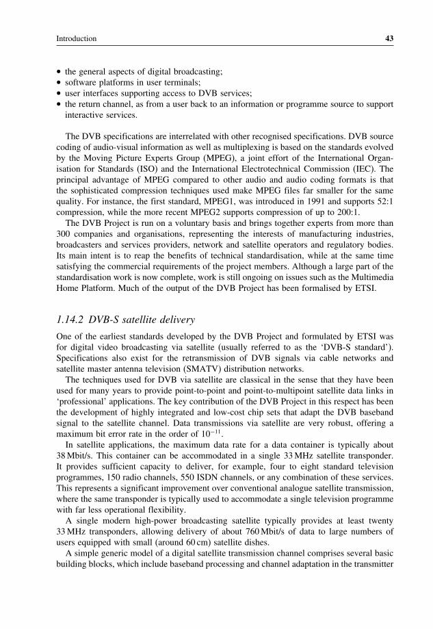
Introduction 43
• the general aspects of digital broadcasting;• software platforms in user terminals;• user interfaces supporting access to DVB services;• the return channel, as from a user back to an information or programme source to supportinteractive services.
The DVB specifications are interrelated with other recognised specifications. DVB sourcecoding of audio-visual information as well as multiplexing is based on the standards evolvedby the Moving Picture Experts Group (MPEG), a joint effort of the International Organ-isation for Standards (ISO) and the International Electrotechnical Commission (IEC). Theprincipal advantage of MPEG compared to other audio and audio coding formats is thatthe sophisticated compression techniques used make MPEG files far smaller for the samequality. For instance, the first standard, MPEG1, was introduced in 1991 and supports 52:1compression, while the more recent MPEG2 supports compression of up to 200:1.The DVB Project is run on a voluntary basis and brings together experts from more than
300 companies and organisations, representing the interests of manufacturing industries,broadcasters and services providers, network and satellite operators and regulatory bodies.Its main intent is to reap the benefits of technical standardisation, while at the same timesatisfying the commercial requirements of the project members. Although a large part of thestandardisation work is now complete, work is still ongoing on issues such as the MultimediaHome Platform. Much of the output of the DVB Project has been formalised by ETSI.
1.14.2 DVB-S satellite delivery
One of the earliest standards developed by the DVB Project and formulated by ETSI wasfor digital video broadcasting via satellite (usually referred to as the ‘DVB-S standard’).Specifications also exist for the retransmission of DVB signals via cable networks andsatellite master antenna television (SMATV) distribution networks.The techniques used for DVB via satellite are classical in the sense that they have been
used for many years to provide point-to-point and point-to-multipoint satellite data links in‘professional’ applications. The key contribution of the DVB Project in this respect has beenthe development of highly integrated and low-cost chip sets that adapt the DVB basebandsignal to the satellite channel. Data transmissions via satellite are very robust, offering amaximum bit error rate in the order of 10−11.In satellite applications, the maximum data rate for a data container is typically about
38Mbit/s. This container can be accommodated in a single 33MHz satellite transponder.It provides sufficient capacity to deliver, for example, four to eight standard televisionprogrammes, 150 radio channels, 550 ISDN channels, or any combination of these services.This represents a significant improvement over conventional analogue satellite transmission,where the same transponder is typically used to accommodate a single television programmewith far less operational flexibility.A single modern high-power broadcasting satellite typically provides at least twenty
33MHz transponders, allowing delivery of about 760Mbit/s of data to large numbers ofusers equipped with small (around 60 cm) satellite dishes.A simple generic model of a digital satellite transmission channel comprises several basic
building blocks, which include baseband processing and channel adaptation in the transmitter

44 Satellite Networking: Principles and Protocols
and the complementary functions in the receiver. Central to the model is, of course, thesatellite transmission channel. Channel adaptation would most likely be done at the transmitsatellite earth station, while the baseband processing would be performed at a point close tothe programme source.
1.14.3 MPEG-2 baseband processing
MPEG is a group of experts drawn from industry who contribute to the development ofcommon standards through an ITU-T and ISO/IEC joint committee. The established MPEG-2 standard was adopted in DVB for the source coding of audio and video information andfor multiplexing a number of source data streams and ancillary information into a single datastream suitable for transmission. Therefore, many of the parameters, fields and syntax usedin DVB baseband processing are specified in the relevant MPEG-2 standards. The MPEG-2standards are generic and very wide in scope. Some of the parameters and fields of MPEG-2are not used in DVB.The processing function deals with a number of programme sources. Each programme
source comprises any mixture of raw data and uncompressed video and audio, where thedata can be, for example, teletext and/or subtitling information and graphical informationsuch as logos.Each of the video, audio and programme-related data is called an elementary stream (ES).
It is encoded and formatted into a packetised elementary stream (PES). Thus each PES is adigitally encoded component of a programme.The simplest type of service is a radio programme, which would consist of a single
audio elementary stream. A traditional television broadcast would comprise three elementarystreams: one carrying coded video, one carrying coded stereo audio and one carrying teletext.
1.14.4 Transport stream (TS)
Following packetisation, the various elementary streams of a programme are multiplexedwith packetised elementary streams from other programmes to form a transport stream (TS).Each of the packetised elementary streams can carry timing information, or ‘time stamps’,to ensure that related elementary streams, for example, video and audio, are replayed insynchronism in the decoder. Programmes can each have a different reference clock, orcan share a common clock. Samples of each ‘programme clock’, called programme clockreferences (PCRs), are inserted into the transport stream to enable the decoder to synchroniseits clock to that in the multiplexer. Once synchronised, the decoder can correctly interpretthe time stamps and can determine the appropriate time to decode and present the associatedinformation to the user.Additional data is inserted into the transport stream, which includes programme specific
information (PSI), service information (SI), conditional access (CA) data and private data.Private data is a data stream whose content is not specified by MPEG.The transport stream is a single data stream that is suitable for transmission or storage. It
may be of fixed or variable data rate and may contain fixed or variable data rate elementarystreams. There is no form of error protection within the multiplex. Error protection isimplemented within the satellite channel adaptor.

Introduction 45
1.14.5 Service objectives
The DVB-S system is designed to provide so-called ‘quasi error free’ (QEF) quality. Thismeans less than one uncorrected error event per transmission hour, corresponding to a biterror rate (BER) of between 10−10 and 10−11 at the input of the MPEG-2 demultiplexer (i.e.after all error correction decoding). This quality is necessary to ensure that the MPEG-2decoders can reliably reconstruct the video and audio information.This quality target translates to a minimum carrier-to-noise ratio C/N requirement for
the satellite link, which in turn determines the requirements for the transmit earth stationand the user’s satellite reception equipment for a given satellite broadcasting network. Therequirement is actually expressed in Eb/N0 (energy per bit to noise density ratio), rather thanC/N , so that it is independent of the transmission rate.The DVB-S standard specifies the Eb/N0 values at which QEF quality must be achieved
when the output of the modulator is directly connected to the input of the demodulator (i.e.in an ‘IF loop’). An allowance is made for practical implementation of the modulator anddemodulator functions and for the small degradation introduced by the satellite channel.The values range from 4.5 dB for rate 1/2 convolutional coding to 6.4 dB for rate 7/8convolutional coding.The inner code rate can be varied to increase or decrease the degree of error protection for
the satellite link at the expense of capacity. The reduction or increase in capacity associatedwith a change in the code rate and the related increase or reduction in the Eb/N0 requirement.The latter is also expressed as an equivalent increase or reduction in the diameter ofthe receive antenna (the size of user’s satellite dish), all other link parameters remainingunchanged.
1.14.6 Satellite channel adaptation
The DVB-S standard is intended for direct-to-home (DTH) services to consumer integratedreceiver decoders (IRD), as well as for reception via collective antenna systems (satellitemaster antenna television (SMATV)) and at cable television head-end stations. It can supportthe use of different satellite transponder bandwidths, although a bandwidth of 33MHzis commonly used. All service components (‘programmes’) are time division multiplexed(TDM) into a single MPEG-2 transport stream, which is then transmitted on a single digitalcarrier.The modulation is classical quadrature phase shift keying (QPSK). A concatenated error
protection strategy is employed based on a convolutional ‘inner’ code and a shortened Reed–Solomon (RS) ‘outer’ code. Flexibility is provided so that transmission capacity can betraded off against increased error protection by varying the rate of the convolutional code.Satellite links can therefore be made more robust, at the expense of reduced throughput persatellite transponder (i.e. fewer DVB services).The standard specifies the characteristics of the digitally modulated signal to ensure
compatibility between equipment developed by different manufacturers. The processingat the receiver is, to a certain extent, left open to allow manufacturers to develop theirown proprietary solutions. It also defines service quality targets and identifies the globalperformance requirements and features of the system that are necessary to meet these targets.

46 Satellite Networking: Principles and Protocols
1.14.7 DVB return channel over satellite (DVB-RCS)
The principal elements of a DVB return channel over satellite (DVB-RCS) system are the hubstation and user satellite terminals. The hub station controls the terminals over the forward(also called outbound link), and the terminals share the return (also called inbound link). Thehub station continuously transmits the forward link in time division multiplex (TDM). Theterminals transmit as needed, sharing the return channel resources using multi-frequency timedivision multiple access (MF-TDMA). The DVB-RCS system supports communications onchannels in two directions:
• Forward channel, from the hub station to many terminals.• Return channels, from the terminals to the hub station.
The forward channel is said to provide ‘point-to-multipoint’ service, because it is sent bya station at a single point to stations at many different points. It is identical to a DVB-Sbroadcast channel and has a single carrier, which may take up the entire bandwidth of atransponder (bandwidth-limited) or use the available transponder power (power limited).Communications to the terminals share the channel by using different slots in the TDMcarrier.The terminals share the return channel capacity of one or more satellite transponders
by transmitting in bursts, using MF-TDMA. In a system, this means that there is a setof return channel carrier frequencies, each of which is divided into time slots which canbe assigned to terminals, which permits many terminals to transmit simultaneously to thehub. The return channel can serve many purposes and consequently offers choices of somechannel parameters. A terminal can change frequency, bit rate, FEC rate, burst length, orall of these parameters, from burst to burst. Slots in the return channel are dynamicallyallocated.The uplink and downlink transmission times between the hub and the satellite are very
nearly fixed. However, the terminals are at different points, so the signal transit timesbetween them and the satellite vary. On the forward channel, this variation is unimportant.Just as satellite TV sets successfully receive signals whenever they arrive, the terminalsreceive downlink signals without regard to small differences in their times of arrival.However, on the uplink, in the return direction from the terminals to the hub, small
differences in transit time can disrupt transmission. This is because the terminals transmitin bursts that share a common return channel by being spaced from each other in time. Forinstance, a burst from one terminal might be late because it takes longer to reach the satellitethan a burst sent by another terminal. A burst that is earlier or later than it should be cancollide with the bursts sent by the terminals using the neighbouring TDMA slots.The difference in transmission times to terminals throughout the footprint of a satellite
might be compensated for by using time slots that are considerably longer than the burststransmitted by the terminals, so both before and after a burst there is a guard time sufficientlylong to prevent collisions with the bursts in neighbouring slots in the TDMA frame. Theone-way delay time between a hub and a terminal varies from 250 to 290ms, depending onthe geographical location of the terminal with respect to the hub. So the time differential,T , might be as large as 40ms. So most TDMA satellite systems minimise guard time byincorporating various means of timing adjustment to compensate for satellite path differences.

Introduction 47
DVB-RCS has two built-in methods of pre-compensating the burst transmission time of eachterminal:
• Each terminal ‘knows’ its local GPS coordinates and therefore can calculate its own bursttransmission time.
• The hub monitors the arrival times of bursts, and can send correction data to terminals ifneed be.
1.14.8 TCP/IP over DVB
DVB-RCS uses the MPEG-2 digital wrappers, in which ‘protocol-independent’ client trafficis enclosed within the payloads of a stream of 188-byte packets. The MPEG-2 digital wrapperoffers a 182-byte payload and has a 6-byte header. The sequence for transmission of InternetTCP/IP traffic includes:
• The TCP/IP message arrives and is subjected to TCP optimisation.• The IP packets are divided into smaller pieces and put into data sections with 96-bit digitalstorage medium – command and control (DSM-CC) headers.
• The DSM-CC data sections are further divided into 188-byte MPEG2-TS packets in thebaseband processing.
• The MPEG2-TS packets then are subjected to channel coding for satellite transmissions.
1.15 Historical development of computer and data networks
Telecommunication systems and broadcasting systems have been developing for over 100years. The basic principles and services have changed little since their beginnings and wecan still recognise the earliest telephony systems and televisions. However, computers andthe Internet have changed greatly in the last 40 years. Today’s systems and terminals arecompletely different from those used 40 or even 10 years ago. The following gives a quickreview of these developments to show the pace of technology progress.
1.15.1 The dawn of the computer and data communications age
The first electronic digital computer was developed during 1943–6. Early computer interfacesused punched tapes and cards. Later terminals were developed and the first communicationbetween terminals and computer over long distances was in 1950, which used voice-gradetelephone links at low transmission speeds of 300 to 1200 kbit/s. Automatic repeat requests(ARQ) for error correction were mainly used for data transmission.
1.15.2 Development of local area networks (LANs)
From 1950 to 1970 research carried out on computer networks led to the development ofdifferent types of network technologies – local area networks (LANs), metropolitan areanetworks (MANs) and wide area networks (WANs).

48 Satellite Networking: Principles and Protocols
A collection of standards, known as IEEE 802, was developed in the 1980s includingthe Ethernet as IEEE802.3, token bus as IEEE802.4, token ring as IEEE802.5, DQDB asIEEE802.6 and others. The initial aim was to share file systems and expensive peripheraldevices such as high-quality printers and graphical plot machines at fast data rates.
1.15.3 Development of WANs and ISO/OSI
The ISO developed the Open System Interconnection (OSI) reference model with sevenlayers for use in wide area networks in the 1980s. The goal of the reference model was toprovide an open standard so that different terminals and computer systems could be connectedtogether if they conformed to the standard. The terminals considered in the reference modelwere connected to a mainframe computer over a WAN in text mode and at slow speed.
1.15.4 The birth of the Internet
Many different network technologies were developed during the 1970s and 1980s and manyof them did not fully conform to international standards. Internetworking between differenttypes of networks used protocol translators and interworking units, and became more andmore complicated as the protocol translators and interworking units became more technologydependent.In the 1970s, the Advanced Research Project Agency Network (ARPARNET) sponsored
by the US Department of Defense developed a new protocol, which was independent ofnetwork technologies, to interconnect different types of networks. The ARPARNET wasrenamed as the Internet in 1985. The main application layer protocols included remote telnetfor terminal access, FTP for file transfer and email for sending mail through computernetworks.
1.15.5 Integration of telephony and data networks
In the 1970s, the ITU-T started to develop standards called integrated services digital net-works with end-to-end digital connectivity to support a wide range of services, includingvoice and non-voice services. User access to the ISDN was through a limited set of standardmultipurpose customer interfaces. Before ISDN, access networks, also called local loops,to the telecommunication networks were analogue, although the trunk networks, also calledtransit networks, were digital. This was the first attempt to integrate telephony and datanetworks and integration of services over a single type of network. It still followed thefundamental concepts of channel- and circuit-based networks used in traditional telecommu-nication networks.
1.15.6 Development of broadband integrated networks
As soon as the ISDN was completed in the 1980s, the ITU-T started to develop broadbandISDN. In addition to broadband integrated services, ATM technology was developed tosupport the services based on fast packet-switching technologies. New concepts of virtual
Introduction 49
channels and circuits were developed. The network is connection oriented, which allowsnegotiation of bandwidth resources and applications. It was expected to unify the telephonynetworks and data networks and also unify LANs, MANs and WANs.From the LAN aspect, ATM faced fierce competition from fast Ethernet. From application
aspects, it faced competition from the Internet.
1.15.7 The killer application WWW and Internet evolutions
In 1990, Tim Berners-Lee developed a new application called the World Wide Web (WWW)based on hypertext over the Internet. This significantly changed the direction of networkresearch and development. A large number of issues needed to be addressed to cope with therequirements of new services and applications, including real-time services and their qualityof service (QoS), which were not considered in traditional Internet applications.
1.16 Historical development of satellite communications
Satellite has been associated with telecommunications and television from its beginning, butfew people have noticed this. Today, satellites broadcast television programmes directly toour homes and allow us to transmit messages and surf the Internet. The following gives aquick review of satellite history.
1.16.1 Start of satellite and space eras
Satellite technology has advanced significantly since the launch of the first artificial satelliteSputnik by the USSR on 4 October 1957 and the first experiment of an active relayingcommunications satellite Courier-1B by the USA in August 1960.
The first international cooperation to explore satellite for television and multiplexed tele-phony services was marked by the experimental pre-operation transatlantic communicationsbetween the USA, France, Germany and the UK in 1962.
1.16.2 Early satellite communications: TV and telephony
Establishment of the Intelsat organisation started with 19 national administration and initialsignatories in August 1964. The launch of the REARLY BIRD (Intelsat-1) marked the firstcommercial geostationary communication satellite. It provided 240 telephone circuits andone TV channel between the USA, France, Germany and the UK in April 1965. In 1967,Intelsat-II satellites provided the same service over the Atlantic and Pacific Ocean regions.From 1968 to 1970, Intelsat-III achieved worldwide operation with 1500 telephone circuitsand four TV channels. The first Intelsat-IV satellite provided 4000 telephone circuits andtwo TV channels in January 1971 and Intelsat-IVa provided 20 transponders of 6000 circuitsand two TV channels, which used beam separation for frequency reuse.

50 Satellite Networking: Principles and Protocols
1.16.3 Development of satellite digital transmission
In 1981, the first Intelsat-V satellite achieved capacity of 12 000 circuits with FDMA andTDMA operations, 6/4GHz and 14/11GHz wideband transponders, and frequency reuse bybeam separation and dual polarisation. In 1989, the Intelsat-VI satellite provided onboardsatellite-switched TDMA of up to 120 000 circuits. In 1998, Intelsat VII, VIIa and Intelsat-VIII satellites were launched. In 2000, the Intelsat-IX satellite achieved 160 000 circuits.
1.16.4 Development of direct-to-home (DTH) broadcast
In 1999, the first K-TV satellite provided 30 14/11-12GHz transponders for 210 TV pro-grammes with possible direct-to-home (DTH) broadcast and VSAT services.
1.16.5 Development of satellite maritime communications
In June 1979, the International Maritime Satellite (Inmarsat) organisation was established toprovide global maritime satellite communication with 26 initial signatories. It explored themobility feature of satellite communications.
1.16.6 Satellite communications in regions and countries
At a regional level, the European Telecommunication Satellite (Eutelsat) organisation wasestablished with 17 administrations as initial signatories in June 1977. Many countries alsodeveloped their own domestic satellite communications systems, including the USA, theUSSR, Canada, France, Germany, the UK, Japan, China and other nations.
1.16.7 Satellite broadband networks and mobile networks
Since the 1990s, significant development had been carried out on broadband networksincluding onboard-switching satellite technologies. Various non-geostationary satellites havebeen developed for mobile satellite services (MSSs) and broadband fixed satellite services(FSSs).
1.16.8 Internet over satellite networks
Since the late 1990s and the start of the twenty-first century, we have seen a dramaticincrease in Internet traffic over the communication networks. Satellite networks have beenused to transport Internet traffic in addition to telephony and television traffic for accessand transit networks. This brings great opportunities as well as challenges to the satelliteindustry. On one hand, it needs to develop internetworking with many different types oflegacy networks; and on the other hand, it needs to develop new technologies to internetworkwith future networks. We have also see the convergence of different types of networksincluding network technologies, network protocols and new services and applications.

Introduction 51
1.17 Convergence of network technologies and protocols
The convergence is the natural progression of technologies pushing and user demands pullingand the development of business cases. Obviously, satellite networking closely follows thedevelopment of terrestrial networks, but is capable of overcoming geographical barriers andthe difficulty of wide coverage faced by terrestrial networks. Figure 1.27 illustrates the visionof a future satellite network in the context of the global information infrastructure.
1.17.1 Convergence of services and applications in user terminals
In the early days, user terminals were designed for particular types of services and had verylimited functions. For example, we had telephone handsets for voice services, computerterminals for data services, and television for receiving television services. Different networkswere developed to support these different types of terminals.As the technology developed, additional terminals and services were introduced into the
existing networks. For example, fax and computer dialup services were added to telephonenetworks. However, the transmission speeds of fax and dialup links were limited by thecapacity of the telephone channel supported by the telephony networks.Computer terminals have become more and more sophisticated and are now capable of
dealing with voice and video services in real time. Naturally, in addition to data services,there are increasing demands to support real time voice and video over data networks.Multimedia services, a combination of voice, video and data, were developed. These
complicate the QoS requirements requiring complicated user terminal and network design,implementation and operation.To support such services over satellite networks for applications such as aeronautics,
shipping, transport and emergency services brings even more challenges. We are starting tosee the convergence of different user terminals for different types of services into a singleuser terminal for all types of services.
Satellite
UrbanIn-Building
Pico-cell
Global
Suburban
Home-cell
Macro-cell dik
In-Home
Micro-cell
Figure 1.27 Satellite in the global information infrastructure

52 Satellite Networking: Principles and Protocols
1.17.2 Convergence of network technologies
Obviously, network services are closely related to the physical networks. To support a newgeneration of services we need a new generation of networks. However, the design of newservices and networks needs significant amounts of investment and a long period of timefor research and development. To get users to accept new services and applications is alsoa great challenge.How about building new services on the existing networking infrastructure? Yes, this
approach has been tried as far as possible, as mentioned previously, fax and computer dialupwere added to telephony networks, and voice and video services to data networks. Thisapproach does not ease the task of developing new services and networks, as the originaldesigns of the networks were optimised for original services. Therefore, new networks haveto be developed for new services and applications.Luckily we do not need to start from scratch. The telephone networks and services on the
existing networks have been developing over the past 100 years; during that time we haveaccumulated a huge amount of knowledge and experience.
1.17.3 Convergence of network protocols
Following the concepts of telecommunication networking principles, attempts were made todevelop new services and networks. Examples of these are the integrated services digitalnetworks (ISDN), synchronous transfer mode (STM) networks, broadband ISDN (B-ISDN)and asynchronous transfer mode (ATM) networks. As telephony services are historicallythe major services in the telecommunication networks, the new networks are biased towardsthese services, and are perhaps emphasising too much on real time and QoS. The results arenot completely satisfactory.Computer and data networks have been developing for about 50 years, during this time
we have also accumulated a significant amount of knowledge and experience in the designof computers and data networks. All the computer and data network technologies haveconverged to the Internet technologies. In LAN, Ethernet is the dominating technology; otherLANs, such as token ring and token bus networks are disappearing. Of course, wirelessLANs are becoming popular. The Internet protocols are now the protocol for computer anddata networking. One of the most important successful factors is backward compatibility,i.e., new network technology should be capable of supporting the existing services andapplications and internetworking with the existing user terminals and network without anymodifications.Following the success of the Internet, significant research and development have been
carried out to support telephony services and other real-time services. As the original designof the Internet was for data services, it was optimised for reliable data services without muchthought given to real-time services and QoS. Therefore, IP telephony cannot be achievedeasily with the level of QoS provided by telecommunication networks.Convergence of network design is inevitable, however, we have to learn from the telecom-
munication networks for QoS and reliable transmission of data from the Internet.The principles of networking are still the same: to improve reliability; increase capacity;
support integrated services and applications; to reach anywhere and anytime; and particularlyimportant for satellite networking to fully utilise limited resources and reduce costs.

Introduction 53
1.17.4 Satellite network evolution
It can be seen that satellite communication started from telephony and TV broadcast terrestrialnetworks. It went on to increase capacity, extend coverage to the oceans for mobile service,and extend services to data and multimedia services.Satellites have become more sophisticated, and have progressed from single transpar-
ent satellites to onboard processing and onboard switching satellites, and further to non-geostationary satellite constellations with inter-satellite links (ISL).Basic satellites have a repeater to relay signals from one side to the other. Satellites with
this type of payload are called transparent satellites. They also called pent-pipe satellites asthey simply provide links between terminals without processing.Some satellites have onboard processing (OBP) as part of the communication subsystems
to provide error detection and error correction to improve the quality of the communicationlinks, and some have onboard switching (OBS) to form a network node in the sky to exploreefficient use of radio resources. Experiments have also been also carried out to fly IP routeronboard satellites due to the recent rapid development of Internet.Satellites have played an important role in telecommunications networks supporting tele-
phony, video, broadcast, data, broadband and Internet services and have become an importantintegrated part of the global information infrastructure providing the next generation ofintegrated broadband and Internet network.
Further reading[1] Brady, M. and M. Rogers, Digital Video Broadcasting Return Channel via Satellite (DVB-RCS) Background
Book, Nera Broadband Satellite AS (NBS), 2002.[2] Eutelsat, Overview of DVB, Annex B to Technical Guide, June 1999.[3] Haykin, S., Communication Systems, 4th edition, John Wiley & Sons, Inc., 2001.[4] ITU, Handbook on Satellite Communications, 3rd edition, John Wiley & Sons, Inc., 2002.[5] Joel, A., Retrospective: telecommunications and the IEEE communications society, IEEE Communications,
May 2002.[6] Khader, M. and W.E. Barnes, Telecommunications Systems and Technology, Prentice-Hall, 2000.
Exercises
1. Explain the meaning of broadband, using the definition given in the ITU-T recom-mendations.
2. Explain the basic concepts of satellite networking and internetworking with terres-trial networks.
3. Explain the terms satellite services, network services and quality of service (QoS).4. Discuss the differences between satellite networking and terrestrial networking
issues.5. Explain the functions of network user terminals and satellite terminals.6. Derive the Shannon power limit and the Shannon bandwidth capacity for large
Eb/N0.7. Explain the basic principles of protocols and the ISO reference model.

54 Satellite Networking: Principles and Protocols
Exercises (continued)
8. Explain the basic ATM reference model.9. Explain the Internet protocol TCP/IP suite.10. Explain the basic concepts of multiplexing and multiple accessing.11. Explain the basic switching concepts including circuit switching, virtual circuit
switching and routeing.12. Explain the evolution process and convergence of network technologies and
protocols.

2Satellite Orbits and NetworkingConcepts
This chapter aims to provide an introduction to the physical layer of satellite networkingconcepts including principles of satellite orbits, satellite link characteristics, transmissiontechniques, multiple access, bandwidth allocation, and satellite availability and diversity.The physical layer is the lowest layer of network protocol stacks, providing real signaltransmission. In the context of the protocol reference model, it provides service to thelink layer above, however, there are no layers below it. It is the layer directly related totransmission media technologies and performs many of the functions of radio communicationsystems. In this chapter we will focus on satellite networking related issues. When you havecompleted this chapter, you should be able to:
• Review the laws of physics including Kepler’s laws and Newton’s laws.• Make use of the laws to explain the characteristics of satellite orbits and calculate satelliteorbit parameters.
• Make use of the laws to design orbits for a single satellite or a constellation of satellitesfor different requirements of satellite networking coverage.
• Appreciate the characteristics of satellite links and calculate the values of the link parameters.• Understand different types of modulation techniques and why the phase shift modulationtechnique is more suitable for satellite transmission.
• Know the important error correcting coding schemes.• Know different bandwidth resource allocation schemes and their applications.• Describe the satellite networking design issues.• Understand the concept of quality of service (QoS) at the physical layer.• Know the quality of a satellite system in terms of availability and the techniques toimprove satellite availability.
Satellite Networking: Principles and Protocols Zhili Sun© 2005 John Wiley & Sons, Ltd

56 Satellite Networking: Principles and Protocols
2.1 Laws of physics
Like terrestrial mobile base stations, satellite communications systems have to be installedon a platform or bus. The laws of physics determine how and where we can put the basestation in the sky to form an integrated part of our network.
2.1.1 Kepler’s three laws
The German astronomer Johannes Kepler (1571–1630) formulated three laws of planetarymotion that also apply to the motion of satellites around earth. Kepler’s three laws are:
1. The orbit of any smaller body about a large body is always an ellipse, with the centre ofmass of the large body as one of the two foci.
2. The orbit of the smaller body sweeps out equal areas in equal time.3. The square of the period of revolution of the smaller body about a large body equals
a constant multiplied by the third power of the semi major axis of the orbital ellipse.
2.1.2 Newton’s three laws of motion and the universal law of gravity
In 1687, the British astronomer, mathematician, physicist and scientist Issac Newton discov-ered the three laws of motion as the following:
1. A body stays motionless, or continues moving in a straight line, unless a force acts on it.2. Any change in movement of a body is always proportional to the force that acts on it, and
is made in the direction of the straight line in which the force acts. It can be described
mathematically as the sum of all vector forces
F acting on a body with a mass of mequals the product of the mass and acceleration of vector
r of the body:
F =md2r
dt2(2.1)
3. Every action has an opposite and equal reaction. In addition to the three laws, Newtonalso discovered the force of gravity (the force that made the apple fall to the ground).
More importantly, he provided a mathematical proof of the force of gravity forming theuniversal law of gravity as the ‘two-body problem’:
F =Gm1m2
1r2
r
r(2.2)
where
F is the vector force of mass m1 on the mass m2 in the direction from m1 tom2G= 6672×10−11 m3/kg/s2 is the universal gravity constant, r is the distance betweenthe two bodies, and
rris the unit vector showing the direction from m1 to m2. Clearly this
can be used to describe the force between the sun and earth by letting m1 be the mass of thesun and m2 be the mass of the earth.

Satellite Orbits and Networking Concepts 57
2.1.3 Kepler’s first law: satellite orbits
Newton derived Kepler’s laws mathematically. Mathematics is the most important tool insystems design and analysis. Here, we should make use of our analytical skills to look intothe fundamental and theoretical aspects of satellite orbits. By taking the following steps, wecan approve Kepler’s first law for the satellite case mathematically.First, apply Newton’s third law to get:
F =GMm1r2
r
r= m
1r2
r
r(2.3)
where the mass of the earth M = 5974× 1024 kg, Kepler’s constant = GM = 3986×1014 m3/s2, and satellite mass is m kg.
Second, applying Newton’s second law of motion, force = mass × acceleration, we get:
d2r
dt2+
r
r3= 0 (2.4)
Then, referring to Figure 2.1 and lettingx =
r /r andy is the unit vector orthogonal to
x , we get:
dr
dt= dr
dt
xt+ r
d
dt
yt (2.5)
d2r
dt2=[d2r
dt2− r
(d
dt
)2]
xt+
[rd2
dt2+2
dr
dt
d
dt
]yt (2.6)
Substituting Equation (2.6) into Equation (2.4) gives:
[d2r
dt2− r
(d
dt
)2]+ u
r2
xt+
[rd2
dt2+2
dr
dt
d
dt
]yt= 0 (2.7)
∆θ
r(t+∆t)
θ
r(t) r(t)
∆r(t)
(a) (b)
∆r(t) = ∆rx + r∆θy
x
∆x(t)=∆θy
∆r(t)
y
∆y(t) = –∆θx
y
∆θ
θ
r(t + ∆t)
θ
Figure 2.1 Vector from earth to satellite

58 Satellite Networking: Principles and Protocols
Hence: [d2r
dt2− r
(d
dt
)2]+
r2= 0 (2.8)
[rd2
dt2+2
dr
dt
d
dt
]= 0 (2.9)
From Equation (2.9), we get:1r
d
dt
(r2d
dt
)= 0;
Hence (r2d
dt
)=D Constant (2.10)
Let u= 1/r in Equation (2.10), we get
d
dt=Du2 (2.11)
Hence:
dr
dt= dr
d
d
dt=
(− 1u2
)du
d
d
dt=−D
du
d(2.12)
d2r
dt2= dr
dt
(dr
dt
)= du
d
d
dt
(dr
dt
)=−D2u2 d
2u
d2(2.13)
Substituting Equations (2.11) and (2.13) into Equation (2.8) gives:
d2u
d2+u=
D2(2.14)
Letting
p= D2
(2.15)
and solving the second-order liner differential equation (2.14) gives the following:
u= 1p+A cos−0
Hence:
r = p
1+pA cos−0(2.16)
where A and 0 are constants, and adjustment can be made so that 0 = 0.

Satellite Orbits and Networking Concepts 59
Therefore, we can represent Kepler’s first law mathematically for satellite orbits as thefollowing equation illustrated in Figure 2.2:
r = p
1+ e cos(2.17)
where e= pA.Note that the earth is at one of the foci. Point A is the nearest point to earth, called perigee;
and point B is the furthest point, called apogee. The radius of earth is RE = 6378km. Therelationships between the parameters are listed as the following:
rmin = hA+RE = a1− e= p/1+ e (2.18)
rmax = hB+RE = a1+ e= p/1− e (2.19)
a= rmin+ rmax/2= hA+hB/2+RE = p/1− e2 (2.20)
b = a2− c21/2 = a1− e21/2 = rminrmax1/2 = p/1− e21/2 (2.21)
p= b2/a (2.22)
c = ae= rmax− rmin/2= hB−hA/2= ep/1− e2 (2.23)
e= c/a= rmax− rmin/rmax+ rmin= hB−hA/hB+hA+2RE (2.24)
p= a1− e2= 2rmaxrmin/rmax+ rmin (2.25)
2.1.4 Kepler’s second law: area swept by a satellite vector
From Equations (2.10) and (2.15), we can get the following equation:
12r2d
dt= D
2= 1
2√p Constant (2.26)
This agrees with Kepler’s second law.
ApogeePerigee
a b
c
r
rmax
rmin
a bθ
ea
r
A
B
FF’ O
hB
hA
satellite
Figure 2.2 Orbit with major axis of orbit (AB) and semi-major axis of orbit (AO)

60 Satellite Networking: Principles and Protocols
2.1.5 Kepler’s third law: orbit period
Integrating from 0 to T , the period of the orbit, we get that the left-hand side of Equation 2.26equals the area of the ellipse and the equation becomes:
ab =T∫
0
12√p dt = T
2√p (2.27)
Hence using Equation (2.22), we can rewrite Equation (2.27) into
T = 2ab√p
= 2
a32 (2.28)
This agrees with Kepler’s third law.According to period T of a satellite completing the orbit, satellite orbits can be classified
as the following types:
• Geostationary orbit, if T = 24 hours and i = 0. The orbit has the same period a siderealday. To be more precise, a sidereal day equals 23 h 56min 4.1 s, which totals 86 154 s.It can be calculated that the semi-major axis a = 42164km and the satellite velocityv= 3075m/s.
• Geosynchronous orbit, if T = 24 hours and 0< i < 90.• Non-geosynchronous orbit, if T = 24 hours. More satellites have to be used to form aconstellation with a number of orbit planes and a few satellites arranged in each plane forcontinuous service to a coverage area.
2.1.6 Satellite velocity
Substituting Equations (2.10), (2.13) and (2.15) into Equation (2.8) gives
[d2r
dt2−(pr3
)2]+
r2= 0
Then making use of Equation (2.25) and integrating both sides of the above equation gives:
12
(dr
dt
)2
+(a1− e2
2r2−
r
)=
∫0dr = E Constant (2.29)
At perigee, there are boundary values r = rmin = a1− e anddr
dt= 0. Substituting into
Equation (2.29) gives:
E = a1− e2
2a21− e2−
a1− e=−
2a(2.30)

Satellite Orbits and Networking Concepts 61
Using Equations (2.5), (2.25), (2.26) and (2.29), the satellite velocity can be calculated as:
2 =(dr
dt
)2
=(dr
dt
)2
+(rd
dt
)2
=(dr
dt
)2
+ a1− e2
r2
= 2E+ 2r
=
(2r− 1
a
)(2.31)
It can be seen from Equations (2.17), (2.18) and (2.19) that v reaches a maximum atperigee where
r = rmin = a1− e, and a minimum at apogee when
r = rmax = a1+ e,
and the speed can be calculated as:
min =√1− e
a1+ e(2.32)
max =√1+ e
a1− e(2.33)
2.2 Satellite orbit parameters
In order to define the trajectory of a satellite in space, orbital parameters are required.The shape of an orbit is described by two parameters: the semi-major axis (a) and theeccentricity (e). The position of the orbital plane in space is specified by means of otherparameters: the inclination (i), the right ascension of the node () and argument of perigee(). The semi-major axis (a) also determines the period (T ) of a satellite orbiting earth.
2.2.1 Semi-major axis (a)
This element specifies the size of the orbit (in km). It is defined as one-half of the majoraxis, which is the length of the chord that passes through the two foci of the orbit’s ellipse.For circular orbits, the semi-major axis (a) is simply the radius of the circle. Figure 2.2illustrates the semi-major axis and other the orbit parameters.
2.2.2 Eccentricity (e)
Eccentricity (e) determines the shape of the orbit. It is a unitless geometric constant with avalue between zero and one. A pure circular orbit has an eccentricity of zero. The followingvalues of e define the types of the satellite orbits:
• For e= 0, the trajectory is a circle.• For e < 1, the trajectory is an ellipse.• For e= 1, the trajectory is a parabola.• For e > 1, the trajectory is a hyperbola.

62 Satellite Networking: Principles and Protocols
2.2.3 Inclination of orbit (i)
The inclination (i) determines the tilt of the orbital plane with respect to the equatorial planeof the earth and is an angle measured in degrees. It is defined as the angle between the twoplanes shown in Figure 2.3. An orbit with an inclination of zero degrees is called an equatorialorbit; an orbit with an inclination of 90 degrees is called a polar orbit. Inclinations of lessthan 90 degrees correspond to direct orbits (i.e., the satellite is rotating around the NorthPole heading east) and inclinations between 90 and 180 degrees correspond to retrogradeorbits (i.e., the satellite is rotating around the North Pole heading west). Inclinations arelimited to a maximum of 180 degrees.According to the inclination angle i of the orbital plane, the angle between the earth’s
equatorial plane and the satellite’s orbital plane, satellite orbits, as shown in Figure 2.4 canbe classified as the following types:
• Equatorial orbit, if i= 0. The orbital is on the same plane as the earth equator.• Incline orbit, if 0< i < 90. The orbital plane and earth equator plane have an angle of idegrees.
• Polar orbit, if i= 90. The orbital plane contains the earth pole.
(a) Orbit plane on the equator plane (i = 0)
•
• •
• i
(b) Inclination of the orbit plane i (0 < i < 90°)
Ascending node ••
••
•
Figure 2.3 Inclination of orbit i
Equatorial orbit
Incline orbit
Polar orbit
Figure 2.4 Equatorial, incline and polar orbits

Satellite Orbits and Networking Concepts 63
Ω
(a) Right ascension of the node Ω (0 ≤ Ω ≤ 360°) (b) Argument of perigee ω (0 ≤ ω ≤ 360°)
•
•
•
•
•• i
Ω
i
•ω
••
•
•
•••
••
Figure 2.5 Right Ascension of the node and argument of perigee
2.2.4 Right ascension of the node () and argument of perigee ()
Right ascension of the node () determines the rotation of the orbital plane, and is anangle measured in degrees. It is defined as the angle in the equatorial plane between thelines formed by the intersection of the orbital planes and the equatorial plane as shown inFigure 2.5(a). Thus, this ‘longitude’ is not a normal longitude tied to the earth’s surface, butis an angle measured in the equatorial plane. It is therefore also called right ascension of theascending node (RAAN). Argument of perigee () determines the rotation of perigee on theorbital plane as shown in Figure 2.5(b), and is an angle measured in degrees.
2.3 Useful orbits
According to Kepler’s third law, the orbital period of a satellite is proportional to its distancefrom earth. Satellites in low orbits, altitudes of a few hundred to a thousand km, have orbitalperiods less than two hours; in contrast, the moon, at an altitude of about 380 000 km, hasan orbital period of about 27 days, which is the base of the lunar month of the Chinesecalendar; and earth has a orbit period of about 365 days as the base of a year.
2.3.1 Geosynchronous earth orbits
Between the extremes is an altitude that corresponds to an orbital period of one day.A satellite in a circular orbit at such an altitude revolves around earth at the same speedas earth’s rotation. This altitude is 35,786.6 km, and the orbit is called a synchronous orgeosynchronous orbit.If the orbital plane of a satellite is not coincident with earth’s equatorial plane, then
the orbit is said to be inclined, and the angle between the orbital plane and the equatorialplane is known as the orbit’s inclination. In a geosynchronous orbit, the point on the earthdirectly below the satellite moves north and south in a narrow figure-eight pattern as shownin Figure 2.6 with northern and southern latitude limits corresponding to the inclination.A constellation of geosynchronous satellites is needed to provide continuous coverage ofan area.

64 Satellite Networking: Principles and Protocols
(a)
geosynchronous orbit
geostationary orbit
(b)
(d)(c)
Satellite
Satellite
Figure 2.6 Footprints of geosynchronous satellites
2.3.2 Geostationary earth orbits (GEOs)
If inclination of a geosynchronous orbit is zero (or near zero), the satellite remains fixed(or approximately fixed) over one point on the equator. Such an orbit is known as a geosta-tionary orbit.An advantage of the geostationary orbit is that antennas on the ground, once aimed at
the satellite, need not continue to rotate. Another advantage is that a satellite in this type oforbit continuously sees about one-third of earth.At an altitude of 35 786.6 km above the equator, the angular velocity of a satellite in this
orbit matches the daily rotation of the earth’s surface, and this orbit has been widely usedas a result. Propagation delay between earth station and satellite is around 0.125ms; thisleads to the widely quoted half-second round-trip latency quoted for communications viageostationary satellite.One disadvantage of the geostationary orbit is that the gravity of the sun and moon disturb
the orbit, causing the inclination to increase. The satellite’s propulsion can counter thisdisturbance, but since the amount of fuel a satellite can carry is limited, increased inclinationmay remain a problem in some scenarios. The geostationary orbit’s finite capacity is anotherdisadvantage; satellites using the same frequencies must be separated to prevent mutualinterference. Providing coverage of high latitudes (above 75) is generally not possible, sofull earth coverage cannot be achieved with a geostationary constellation.
2.3.3 High elliptical orbits (HEOs)
High elliptical orbits (HEOs) differ from the circular orbits. They provide coverage onlywhen the satellite is moving very slowly relative to the ground while at apogee, furthestfrom the earth’s surface, and power requirements in link budgets are dimensioned for thisdistance. Figure 2.7 illustrates a typical elliptical orbit.These orbits are generally at an inclination of 63.4 degrees so that the orbit is quasi-
stationary with respect to the earth’s surface. This high inclination enables coverage of high

Satellite Orbits and Networking Concepts 65
(a)
Elliptical orbit
geostationary orbit
(b)
Satellite moving at fastest speed at this point.
Satellite movingslowest speed at this point.
Figure 2.7 A typical high elliptical orbit
latitudes, and Russian use of Molnya and Tundra elliptical orbits for satellite television tothe high-latitude Russian states is well known.As elliptical orbits are the exception rather than the general rule, and generally provide
targeted selection, rather than general worldwide coverage, we will not consider themfurther here.
2.3.4 Notations of low earth orbit (LEO) satellite constellations
LEO satellites move faster than the rotation of earth. Therefore, they appear to continuouslycirculate around the earth. Figure 2.8 illustrates the orbit and footprint of an LEO satellite.A constellation of satellites is needed to provide global coverage.Satellite orbit plane and the point on the orbit can allocate a satellite position. For a
constellation of satellites, there are simple notations or rules to describe it for a globalcoverage. There are two forms of notations used to describe satellite constellations in theliterature – Walker notation and Ballard notation:
• Walker notation (N/P/p): this notation refers to: (number of satellites per plane/numberof planes/number of distinct phases of planes to control spacing offsets in planes).
• Ballard notation (NP, P, m): this notation refers to: (total number of satellites NP, numberof planes P, harmonic factor m describing phasing between planes).
(a)
Low earth orbit
geostationary orbit
(b)
Satellite Satellite
Figure 2.8 Footprint of a LEO satellite

66 Satellite Networking: Principles and Protocols
The Walker notation is more commonly seen, although the Ballard notation can moreaccurately describe possible offsets between planes.
2.3.5 Orbital perturbations
There are many subtle effects that perturb earth satellite orbits, invalidating the simple orbitspredicted by two-body gravity equations. Some of the factors that perturb the orbit are:
• Earth’s oblateness: the earth bulges at the equator, which leads to a much more complexgravity field than the spherically symmetric field of a ‘point’ gravity source.
• Solar and lunar effects: these effects of the sun and moon are the most influential gravi-tational forces on earth satellites besides the earth’s own field.
• Atmospheric drag: the friction that a satellite encounters as it passes through the diffuseupper layers of the earth’s atmosphere.
• Solar radiation pressure: solar radiation pressure is caused by collisions between thesatellite and photons radiating from the sun, which are absorbed or reflected.
2.3.6 Satellite altitude and coverage
The higher the altitude, the longer the distance one is able to see. The longer the distance, thehigher the transmission power is required for communications. Figure 2.9 illustrates thesesimple relationships.It can be seen that the GEO satellite has the highest altitude covering the largest area, the
LEO satellite has the lowest altitude covering the smallest area and the MEO is in between.The GEO satellite also provides a fixed and continuous coverage of the area, but the LEOand MEO satellites will gradually move away from the coverage areas. These imply that theLEO and MEO satellites provide advantages for small and lower terminals at the cost ofcomplicated constellations of satellite systems. Such complications also incur the high costof deployment and operation of the constellations.
Satellites
Figure 2.9 Relationships between altitude and coverage
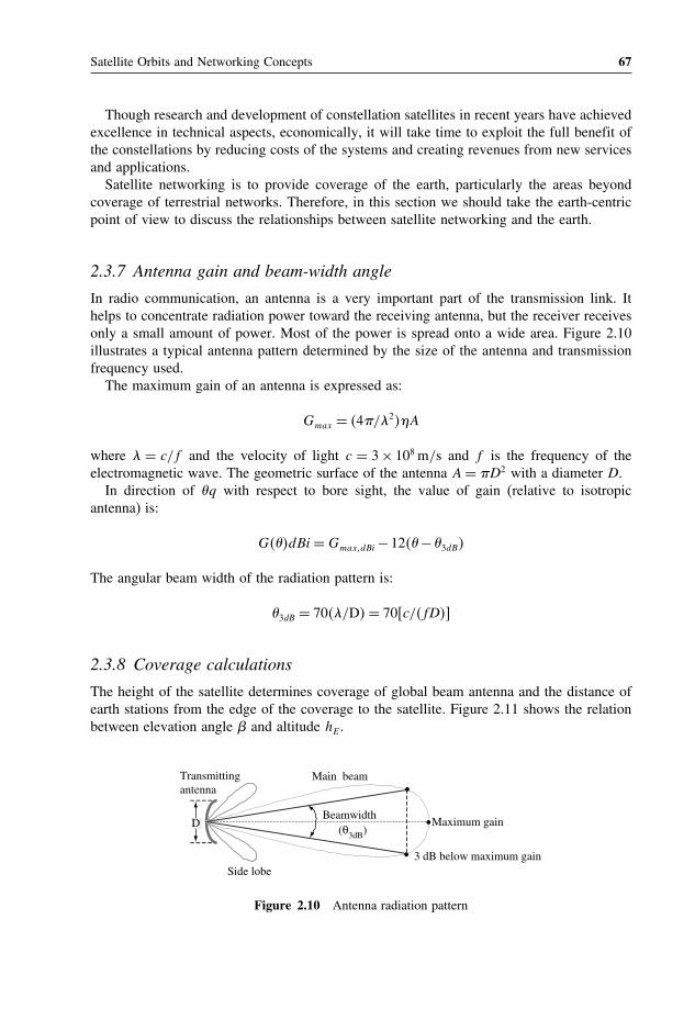
Satellite Orbits and Networking Concepts 67
Though research and development of constellation satellites in recent years have achievedexcellence in technical aspects, economically, it will take time to exploit the full benefit ofthe constellations by reducing costs of the systems and creating revenues from new servicesand applications.Satellite networking is to provide coverage of the earth, particularly the areas beyond
coverage of terrestrial networks. Therefore, in this section we should take the earth-centricpoint of view to discuss the relationships between satellite networking and the earth.
2.3.7 Antenna gain and beam-width angle
In radio communication, an antenna is a very important part of the transmission link. Ithelps to concentrate radiation power toward the receiving antenna, but the receiver receivesonly a small amount of power. Most of the power is spread onto a wide area. Figure 2.10illustrates a typical antenna pattern determined by the size of the antenna and transmissionfrequency used.The maximum gain of an antenna is expressed as:
Gmax = 4/ 2A
where = c/f and the velocity of light c = 3× 10⁸ m/s and f is the frequency of theelectromagnetic wave. The geometric surface of the antenna A= D2 with a diameter D.
In direction of q with respect to bore sight, the value of gain (relative to isotropicantenna) is:
GdBi=GmaxdBi−12−3dB
The angular beam width of the radiation pattern is:
3dB = 70 /D= 70c/fD
2.3.8 Coverage calculations
The height of the satellite determines coverage of global beam antenna and the distance ofearth stations from the edge of the coverage to the satellite. Figure 2.11 shows the relationbetween elevation angle and altitude hE .
Transmittingantenna
Side lobe
Main beam
Beamwidth(θ3dB)
Maximum gain•
•
• 3 dB below maximum gain
D
Figure 2.10 Antenna radiation pattern

68 Satellite Networking: Principles and Protocols
B
α
A
dRE
RE
hE
O SS’
H
p
β
β
θ
Figure 2.11 Relation between elevation angle and altitude
In Figure 2.11, OPS is a right-angled triangle. We can calculate as the following:
Sp= hE +RE sina (2.34)
Op= hE +RE cosa
Ap= Sp tan (2.35)
As we also have Ap = AS sin together with Equations (2.34) and (2.35), we can get:AS = Sp tan/ sin= hE +RE sina/ cos.For a special case when = 0AS = hE +RE sina. We can also calculate cosa =
RE/hE +RE, then, sin2 a= 1− cos2 a= 1−RE/hE +RE
2. Therefore:
AS2 = hE +RE2−R 2
E (2.36)
We can also calculate directly, as OAS becomes a right-angled triangle when = 0
AS2+R 2E = hE +RE
2
This gives the same result as Equation (2.36).The maximum coverage area can be calculated as:
Coverage= 2REH = 2R 2E 1−RE/hE +RE
2.3.9 Distance and propagation delay from earth station to satellite
Two angles are used to locate the satellite from any point on the surface of the earth:
1. Elevation angle (): the elevation angle is the angle between the horizon at the pointconsidered and the satellite, measured in the plane containing the point considered, thesatellite and the centre of the earth.
2. Azimuth angle (): the azimuth angle is the angle measured in the horizontal plane ofthe location between the direction of geographic north and the intersection of the planecontaining the point considered, the satellite and the centre of the earth.

Satellite Orbits and Networking Concepts 69
T
Aζ
satellite
N
RE
O hϕ
B
L
Ø
pR
l
Figure 2.12 Distance between earth station and satellite
The distance from the centre of the earth to the satellite is: r = h+REThe distance between earth station and satellite can be calculated as:
R2 = R 2E + r2−2REr cosØ
tan= cosØ− RE/r/ sinØ
sin= sinL cos/ sinØ
where cosØ = cosL cos cos l+ sin sin l, for GEO, we have = 0, then cos = 1 andsin= 0.The propagation delay from an earth station to a satellite can be calculated as:
Tp = R/c
where the velocity of light c = 3×10⁸ m/s.Therefore, one-way propagation delay from one station to another station is:
Tp = R1+R2/c
where R1 and R2 are the distances from earth stations to the satellite.
2.4 Satellite link characteristics and modulations for transmissions
The basic transmission signal components include the carrier wave and modulating signal.The carrier wave is a continuous sinusoidal wave, which contains no information. Themodulating signal is the message signal to be transmitted over the carrier. It can modu-late (change) the amplitude, frequency or phase of the carrier wave, leading to differentmodulation schemes: amplitude modulation (AM), frequency modulation (FM) and phasemodulation (PM). In the receiving end, the demodulator can separate the message signal

70 Satellite Networking: Principles and Protocols
Carrier wave
–1.5–1.0–0.50.00.51.0
1.5
–1.5–1.0–0.50.00.51.01.5
–1.5
–1.0
–0.5
0.0
0.5
1.0
1.5
Am
plitu
deA
mpl
itude
Am
plitu
deA
mpl
itude
–1.5–2.0
–1.0–0.50.00.51.01.52.0
–1.5
–1.0
–0.5
0.0
0.5
1.0
1.5
Modulating signal
Am
plitu
de
Amplititude modulation
Frequency modulation
Phase shift modulation
Time
Figure 2.13 Carrier waves, modulating signals and modulated signals
from the carrier wave by a demodulation process depending on the modulation schemeused in transmission. Figure 2.13 illustrates the different modulating processes. Modulationsenable transmission of message signals at the carrier frequency. They can be used to providemultiple accesses to the radio frequency bands at the frequency domain.Beside the modulation signal, the satellite propagation channel conditions may also cause
changes to the amplitude, frequency or phase of the carrier wave. Therefore, it can cause

Satellite Orbits and Networking Concepts 71
transmission errors. It is also important to have an error correction coding scheme to recoveras much as possible errors occurred during the transmission.
2.4.1 Satellite link characteristics
Unlike cable, the quality of the satellite link cannot be controlled. The satellite link maycause propagation impairments depending on the following factors:
• Operating frequency: as signal attenuation by gas absorption, the severity of troposphericimpairments increases with frequency.
• Antenna elevation angle and polarisation: the length of the propagation path passingthrough the troposphere varies inversely with elevation angle. Accordingly, propagationlosses, noise and depolarisation also increase with the decreasing elevation angle. Rainattenuation is slightly polarisation sensitive. Depolarisation is also polarisation sensitive,with circular polarisation being the most susceptible.
• Earth station altitude: because less of the troposphere is included in paths from higheraltitude sites, impairments are less at high altitude.
• Earth station noise temperature: this is the level of sky noise temperature to system noisetemperature, thus the effect of sky noise on the downlink signal-to-noise-ratio.
• Local meteorology: the amount and nature of the rainfall in the vicinity of the earth stationare the primary factors in determining the frequency and most propagation impairments.
• Figure of merit (G/T ): a figure of merit expresses the efficiency of a receiver; G is theoverall gain in decibels and T is the noise temperature, expressed in decibels relativeto 10 Kelvin. Hence G/T is expressed in decibels, with the appended symbol dB/K toindicate the Kelvin scale of temperature.
The free-space loss is the major power loss due to long propagation of the satellite link.Though it is larger than all the other losses, the other losses can also play important part inadding several dB. At frequencies of 10GHz and above, losses due to atmospheric absorptionand rain can be significant. At these frequencies, electromagnetic waves interact and resonatewith molecules of atmospheric gases to cause signal attenuation. The most important reso-nant attenuation occurs at 22.235GHz due to water vapour and between 53 to 65GHz due tooxygen. Loss at other frequencies is usually small (less than 1 dB). These atmospheric lossescan be calculated and included in the link equation to determine its impact on the overall quality.At lower frequencies, less than 1GHz, losses due to multipath fading and scintilla-
tion are predominant. Faraday rotation due to the total electron count in the atmospherebecomes significant, but, using proper polarisation, these losses can be controlled in high-gain communications.
2.4.2 Modulation techniques
As an example, we can describe the carrier wave mathematically as:
crt= Ac cos2fct
where Ac is carrier amplitude and fc is carrier frequency.

72 Satellite Networking: Principles and Protocols
We can describe the amplitude-modulated wave as:
st= Ac+kamt cos2fct
where mt is the signal and ka is the amplitude sensitivity of the modulator.We can describe the frequency-modulated wave as:
st= Ac cos2fc+kfmtt
where kf is the frequency sensitivity of the modulator.We can describe the phase-modulated wave as:
st= Ac cos2fct+kpmt
where kp is the phase sensitivity of the modulator.In the frequency-modulated wave, let f t= 2fc+kfmtt, it can be seen that mt
causes the change of frequency f = kfmtt which is equivalent to the change of phasef = 2fc+ft = 2fc+kfmtt, hence:
df t
dt= 2fc+2kfmt and f t= 2fct+2kf
t∫0
mtdt
i.e., the frequency-modulated wave is generated by using the carrier frequency and integrationof the message signal.In the phase-modulated wave, pt = 2fct+ kpmt, i.e., the phase-modulated wave
is generated by using the carrier frequency and the message signal. Therefore, the phase-modulated wave can be deduced from the frequency-modulated wave, and vice versa. Phasemodulation and frequency modulation are also called angle modulation.
2.4.3 Phase shift keying (PSK) schemes for satellite transmissions
As the satellite link conditions may change during transmission for digital transmission, thealtitude of the transmission may also change with the link condition. It is difficult to use AM.FM is difficult to implement and not efficient on bandwidth utilisation. Compared with theAM and FM schemes, PM has the advantages of FM and is easy to implement. Therefore,for satellite transmission, PM is used, and many different PM schemes have been developedto trade off among power, frequency and implementation efficiency.The simplest modulation scheme is BPSK, which is capable of transmitting one bit in a
carry frequency period. The higher the modulation order, the larger the bandwidth efficiencyis. QPSK, for example, is capable of transmitting two bits in the carry frequency period forthe same Eb/N0 value, but at the cost of error performance.
It is called coherent demodulation or coherent detect if the local oscillator is exactlycoherent or synchronous, in both frequency and phase, with the carrier wave used formodulation. Otherwise, it is called non-coherent demodulation or non-coherent detect wherea different technique is used for demodulation using match filters.

Satellite Orbits and Networking Concepts 73
O••
– E + E
Messagepoint 1
Messagepoint 2
φ1
Figure 2.14 Signal-space diagram for coherent BPSK
2.4.4 Binary phase shift keying (BPSK)
In a coherent binary PSK (BPSK) system, the pair of signals used to represent binary symbols1 and 0, respectively, is defined as:
s1 =
√2Eb
Tb
cos2fct
s2 =√2Eb
Tb
cos2fct+=−√2Eb
Tb
cos2fct
These can be represented in a signal-space diagram with a basis function of unit energy:
1 =√
2Tb
cos2fc
as shown in Figure 2.14.
2.4.5 Quadrature PSK (QPSK)
Similarly, in a coherent quadrature PSK (QPSK) system, there are four signal vectorsdefined as:
si =
√E cos2i−1
4
−√E cos2i−1
4
i= 1234
These can be represented in a signal-space diagram with two orthogonal basis functions ofunit energy
1 =√
2Tb
cos2fc and 2 =√
2Tb
sin2fc
as shown in Figure 2.15.

74 Satellite Networking: Principles and Protocols
O φ1
Message
point 1
(10)
Message
point 2
(00)
Message
point 3
(01)
Message
point 4
(11)
– E/2
– E/2
– E/2
– E/2
Figure 2.15 Signal-space diagram for coherent QPSK
2.4.6 Gaussian-filtered minimum shift keying (GMSK)
To improve the bandwidth efficiency and error performance, two techniques can be applied:minimum phase shift and shaping the rectangular pulse through a Gaussian filter.Let W denote the 3 dB baseband bandwidth of the pulse-shaping filter. The transfer
function Hf and impulse response ht of the pulse filter are defined as the followingrespectively:
Hf= exp
(− log2
2
(f
W
)2)
and
hf =√
2log2
exp(− 22
log2W 2t2
)
The responses of a Gaussian filter to a rectangular pulse of unit amplitude and durationTb (centred in the origin) are given by:
gt=∫ Tb/2
Tb/2ht− d =
√2log2
W∫ Tb/2
Tb/2exp
(− 22
log2W 2t− 2
)d
The pulse response gt constitutes the frequency shaping pulse of the GMSK modu-lator, with the dimensionless time-bandwidth product WTb playing the role of a designparameter.As WTb is reduced, the time spread of the frequency shaping pulse is correspondingly
increased. The limiting condition WTb = corresponds to the case of ordinary MSK, andwhen WTb is less than unity, increasingly more of the transmit power is concentrated insidethe pass band of the GMSK signal.

Satellite Orbits and Networking Concepts 75
2.4.7 Bit error rate (BER): the quality parameter of modulation schemes
Inherently, bit errors occur in satellite channels during transmission. The bit error rate (BER)depends on the signal-to-noise ratio (S/N ) at the receiver. Thus for an acceptable level oferror rate, a certain minimum signal-to-noise ratio must be ensured at the receiver and hencemaintained at the transmitter.The relationship between C/N and the bit error rate of the channel is a measure of
performance for a digital link. This is computed from the carrier-to-noise density ratio, C/N0
ratio, for a particular modulation scheme by:
Eb
N0
=C/N0−10 log10DataRateC/N −10 log10DataRate/Bandwidth
(2.37)
The data rate over bandwidth ratio, R/B, is called the spectrum efficiency or bandwidthefficiency of the modulation. For a given bandwidth, the Eb/N0 value has to be large enoughto achieve the transmission bit rate with a good error performance in terms of bit error ratioor probability of bit error.There are error functions to compute symbol error rates. The number of bits per symbol
is log2M, where M is coded levels of modulation scheme. The bit error rate pb is relatedto the symbol error rate Ps by:
pb =Ps
log2M(2.38)
Theoretically, error performance can be calculated using the Gaussian probabilities as thefollowing:
PX > x+x=Qy=∫
y
1√2
e−z2/2dz
Q(0)= 1/2,Q(−y)= 1− (y),when y ≥ 0
erfcy≡ 2√
∫
ye−z2dz= 2Q
√2y
Table 2.1 shows the error performance common for some popular modulation schemes.Figure 2.16 shows some results calculated using the formulas in the table.
2.4.8 Satellite networking in the physical layer
In the context of the protocol reference model, satellite networking starts from the physicallayer. The physical layer accepts frames from the link layer, then transmits the frame in theform of a bit stream to its peer entity via the satellite. Depending on the implementation ofthe satellite communication payload, there can be a transparent satellite simply forwardingthe radio signal from an uplink to a downlink, or there can be an onboard processor (OBP)processing the digital signal then forward to the downlink. It is also possible to have evenmore complicated payloads including switching or routing functions.

76 Satellite Networking: Principles and Protocols
Table 2.1 Modulation methods
Modulation scheme PE (symbol)
Coherent QPSK12erfc
√Eb/N0
Coherent BPSK
Coherent MPSK
MSK12erfc
√Eb/N0
GMSK12erfc
√Eb/2N0
where is a constant dependingon the time-bandwidth product WTb
Coherent BFSK12erfc
√Eb/2N0
No coherent DPSK12exp−Eb/N0
No coherent BFSK12exp−Eb/2N0
Noise performance of modulation schemes
1.0E – 1
1.0E – 2
1.0E – 3
1.0E – 4
1.0E – 5
1.0E + 0
–5 –2.5 0 2.5 5 7.5 10 12.5
Eb/N0
Bit
erro
r ra
te (
BE
R)
Coherent QPSK
Cpherent BFSK
DPSK
Noncoherent BFSK
Figure 2.16 Noise performance of modulation schemes
Here the discussion focuses on the physical layer dealing with transmission and receivingthe bit streams and radio signals over satellite. Figure 2.17 shows the physical layer functionsof satellite networking in the context of the protocol reference model. It can be seen that auser terminal generates a bit stream. The encoders process the stream with error correctionencoding function and channel coding function. The modulator uses the encoded signal tomodulate the carry to transmit the signal over the satellite link. In the other side of thesatellite network, a reverse processing takes place before getting the bit stream to the otheruser terminal. Within the satellite network, the processing is transparent to users, which caninclude different OBP functions or even inter-satellite links.In a wired network, a digital bit stream can be encoded into baseband signals and trans-
mitted directly along the wire. However, satellite uses radio links for transmission, hence

Satellite Orbits and Networking Concepts 77
User terminal
User terminal
7
6
5
4
3
2
7
6
5
4
3
2
Satellite terminal
1. Physical
Satellite terminal
1. Physical1 1 01010101010
bit streamCoder Modulator
Satellite channel bit stream
DecoderDemodulator
Satellite channel
01010101010
DecoderDemodulator
Satellite channel Coder Modulator
Satellitechannel
Switching functions
Figure 2.17 Block diagram of physical layer functions of satellite networks
modulation is required so that the signal can be transmitted over a radio channel or carrier.In addition, error correction coding is used before the channel coding to correct possibletransmission errors, hence improving transmission quality by reducing probability of error.
2.5 Forward error correction (FEC)
FEC techniques try to introduce some redundancy in the transmitted data, such that whena receiver receives the data, it uses this redundancy to detect and correct errors if there areany caused by transmission, as illustrated in Figure 2.18. FEC codes consist of a wide rangeof classes. We give brief introductions to only some of them including linear block codes,cyclic codes, trellis and convolutional codes and turbo codes.
Physicallayer
transmit
(n, k) Encoder Modulator
Demodulator(n, k)
Encoder
Satellite Channel
d1, d2,…, dk
d1, d2,…, dk
c1, c2,…, cn
c1, c2,…, ck
Data bits Code bits
Data bits Code bits
Physicallayer
Receive
Figure 2.18 Forward error correction (FEC) coding

78 Satellite Networking: Principles and Protocols
2.5.1 Linear block codes
Block codes are ‘memory-less’ codes that map k input binary signals to n output binarysignals, where n > k for redundancy.
Let m = m0m1 mk−1 be the message bits, b = b0 b1 bn−k−1 and P be thek× n−k coefficient matrix known to transmitter and receiver, we can generate the paritybits as the following:
b =mP (2.39)
If the code word c = bm is transmitted, we will be able to detect some errors or even
correct some errors by making use of Equation (2.39).An example of a linear coder is the Hamming coder n k, where block length is n =
2r − 1, number of message bits is k = 2r − r− 1 (or k+ r− 1 = 2r), and number of paritybits n−k= r.The Bose–Chaudhuri–Hocquenghem (BCH) code is a class of linear block code with
the parameters: block length is n = 2m − 1, number of message bits is k ≥ n−mt, andminimum distance is dmin ≥ 2t+ 1, where m is any integer number and t = 2m− 1/2 isthe maximum number of detectable errors.The Reed–Solomon code (RS code) is a subclass of non-binary BCH codes. An RS coder
of n k is used to code m bit symbols into blocks consisting of n = 2m − 1 symbols= m2m − 1 bits. A t-error correcting RS code has the parameters of: block length isn= 2m−1 symbols, message size is k symbols, parity check size is n−k= 2t symbols,and minimum distance is dmin ≥ 2t+1 symbols.
2.5.2 Cyclic codes
Let gX be the polynomial of least degree of n−k, also called the generator polynomialof cyclic code, defined as the following:
gX= 1+n−k−1∑i=1
giXi+Xn−k
LetmX=m0X1+m1X
2+· · ·+mk−1Xk−1, and bX= b0X
1+b1X2+· · ·+bn−k−1X
n−k−1,we can divide Xn−kmX by the generator polynomial gX to obtain the remainder bXand add bX to Xn−kmX to get cX.Cyclic coding is often used for error check purposes because of its ability to detect error
burst, also called cyclic redundancy check (CRC) code. Table 2.2 shows some useful CRCcodes.Binary n k CRC codes are capable of detecting the following error patterns:
• All error bursts of length n−k or less.• A fraction of error bursts of length equal to n−k+1 that the fraction equals to or greaterthan 1−2−n−k−1.

Satellite Orbits and Networking Concepts 79
Table 2.2 Cyclic redundancy check (CRC) code
Code Generator polynomial gX n−k
CRC-12 code 1+X+X2+X3+X12+X12 12CRC-12 code (USA) 1+X2+X15+X16 16CRC-ITU code 1+X5+X12+X16 16
• All combinations of dmin −1 or fewer errors, where dmin is the minimum distance of alinear block code. The distance is defined as the number of locations of a pair of codevectors with their respective differing, also called the Hamming distance.
• All error patterns with an odd number of errors if the generator polynomial g(X) for thecode has an even number of non-zero coefficients.
2.5.3 Trellis coding and convolutional codes
Trellis codes use ‘memory’ by remembering K− 1 input signals immediately precedingthe target block of L input signals. These K− 1+L = K+L− 1 input binary signalsare used in the generation of nK−1+L output binary signals corresponding to L inputsignals. Therefore the code rate is L/nK+L−1.Convolutional coding is a subset of trellis codes. The convolutional encoder can be
associated to a finite state machine storing k− 1 message bits. At time j, the portion ofthe message sequence contains the most recent k bits mj−k+1mj−k+2 · · · mj−1mj, wheremj is the current bit. A convolutional decoder takes into account such memory, when tryingto estimate the most likely sequence of data that produce the received sequence of codebits. This is called maximum likelihood method for decoding convolutional codes. In 1967,Andrew Viterbi developed a technique of decoding convolutional codes using this methodthat has since become the standard for decoding convolutional codes.
2.5.4 Concatenated codes
Linear block coders are more effective to correct burst of errors and convolutional codersare more effective on random errors, however, they can produce burst errors if there are toomany random errors. In 1974, Joseph Odenwalder combined these two coding techniques toform a concatenated code.The arrangement is that a block code is used as internal code first, then a convolutional
code follows second as external code for encoding; on decoding, external convolutional codefollows first, then the internal block code follows second.Performance can be further enhanced if interleaving techniques between the two coding
stages mitigate any burst that might be too long for the block code to deal with effectively.Interleaving techniques are input-output mapping functions that permute the order of a
stream of bits or symbols so that the position of the interleaved bit stream is independentfrom the original bit stream, and a burst of errors can be randomised into single randomerrors spreading into the bit stream when de-interleaved. A device or a function block of aninterleaving technique is often called an interleaver.

80 Satellite Networking: Principles and Protocols
2.5.5 Turbo codes
Turbo codes are the most powerful FEC, developed in 1993 by Claude Berrou. They enablecommunication transmissions closer to the Shannon limit. A turbo code consists of twocoders and one interleaver so that the extrinsic information is used recursively to maximisethe probability that the data is decoded correctly. Each of the two codes can be any of theexisting coders. Without going into the detail of turbo codes, we will only illustrate theconcepts of the turbo coder and decoder using Figures 2.19 and 2.20, respectively.The encoder is simple and straightforward. The decoder is more complicated, where the
extrinsic information is used recursively. The most convenient representation for this conceptis to introduce the soft estimation of x = d 1d 2d 3d 4 in decoder 1, expressed as thelog-likelihood ratio:
l1di= log
(Pdi = 1x y l2xPdi = 0x y l2x
)i= 1234
l2di= log
(Pdi = 1x z l1xPdi = 0x z l1x
)i= 1234
l1x=4∑1
l1di l1x= l1x− l2x
l2x=4∑1
l2di l2x= l2x− l1x
where l2x is set as 0 in the first iteration. An estimation of the message x’ = d’1d’2d’3d’4is calculated by hard limiting that log-likelihood ratio l2x at the out put of decoder 2, as thefollowing
x = signl2x
where the sign function operates on each element of l2x individually.
Encoder 1
Encoder 2
Interleaver
d4, d3, d2, d1
d4, d3, d2, d1
z4, z3, z2, z1
y4, y3, y2, y1z4y4d4, z3y3d3, z2y2d2, z1y1d1
Figure 2.19 Block diagram of turbo encoder

Satellite Orbits and Networking Concepts 81
Extrinsic information
After last iteration
Loop back
Decoder 1
ý4, ý3, ý2, ý1
Interleaver Decoder 2
Extrinsic information
Interleaver
Harder limiter
d’4, d’3, d’2, d’1
Extrinsic information
d4, d3, d2, d1
z4, z3, z2, z1
Figure 2.20 Block diagram of turbo decoder
2.5.6 Performance of FEC
The receiver can decode the data in most cases even it has been corrupted during transmission,making use of FEC techniques. The receiver may not be able to recover the data if thereare too many bits corrupted, since it can only tolerate a certain level of errors. We haveseen that the Eb/N0 is the parameter affecting the error performance of satellite transmissionfor given codes and bandwidth resources. The FEC enables satellite links to tolerate highertransmission errors than the uncoded data in terms of error performance. This is very usefulas sometimes satellite transmission alone may be difficult to achieve a certain level ofperformance due to limited transmission power at certain link conditions.Let take an example: assumeR is the information rate, the coded data rateRc, as defined for a
(n, k) block code, where n bits are sent for k information bits isRc = Rn/k. The relationshipof required power between the coded and uncoded data for the same bit error rate is:
C/Rc/N0 = k/nC/R/N0 = k/nEb/N0
These codes, at the expense of larger required bandwidth or larger overhead (reducedthroughput), provide a coding gain to maintain the desired link quality at the same availableEb/N0. Without going through detailed mathematical analysis, we will only give a briefdescription using Figure 2.21.
2.6 Multiple access techniques
Considering that satellite communications use multiple access schemes on a shared medium.The access scheme refers to the sharing of a common channel among multiple users ofpossible multi-services. There are three principal forms of multiple access schemes as shownin Figure 2.22:
• frequency division multiple access (FDMA);• time division multiple access (TDMA); and• code division multiple access (CDMA).
Multiplexing is different from multiple access: it is a concentration function which sharesthe bandwidth resource from the same places while and multiple access shares the sameresource from different places as shown in Figure 2.23.

82 Satellite Networking: Principles and Protocols
Performance of FEC codes
1.0E – 06
1.0E – 05
1.0E – 04
1.0E – 03
1.0E – 02
1.0E – 01
1.0E + 00
0 1 2 3 4 5 6 7 8 9 10
Eb/No (dB)
Bit
Err
or R
ate
(BE
R)
Uncoded
Concatenated
ConvolutionalTurbo
Shannonlimit at coderate r = 1/2
Figure 2.21 Comparison of FEC codes
Frequency/ Bandwidth
N...321
TimeFDMA
Frequency/ Bandwidth
1 2 3 ................N
TimeTDMA
Frequency/ Bandwidth
N..321
TimeCDMA
Code
N...321
Figure 2.22 Multiple access techniques: FDMA, TDMA and CDMA
Multiplexing
Multiple accesses
Figure 2.23 Comparison between the concepts of multiplexing and multiple access

Satellite Orbits and Networking Concepts 83
2.6.1 Frequency division multiple access (FDMA)
FDMA is a traditional technique, where several earth stations transmit simultaneously, buton different frequencies into a transponder.FDMA is attractive because of its simplicity for access by ground earth stations. Single
channel per carrier (SCPC) FDMA is commonly used for thin-route telephony, VSATsystems and mobile terminal services for access networks. Multiplexing a number of channelsto share a carrier for transit networks also uses FDMA. It is inflexible for applications withvarying bandwidth requirements.When using multiple channels per carrier for transit networks, FDMA gives significant
problems with inter-modulation products (IMPs), and hence a few dB of back-off fromsaturation transmission power is required to overcome the problem of non-linearity at highpower. The resultant reduction in EIRP may represent a penalty, especially to small terminals.
2.6.2 Time division multiple access (TDMA)
In TDMA, each earth station is allocated a time slot of bandwidth for transmission ofinformation. Each time slot can be used to transmit synchronisation and control and userinformation. The synchronisation is achieved by using the reference burst time. TDMA ismore convenient for digital processes and transmission. Figure 2.24 shows a typical exampleof TDMA.Only one TDMA carrier accesses the satellite transponder at a given time, and the full
downlink power is available for access. TDMA can achieve efficiencies in power utilisationand also in bandwidth utilisation if the guard time loss is kept at minimum when using moreaccurate timing techniques. This is widely used for transit networks due to high bandwidthutilisation at high transmission speed.Clearly TDMA bursts transmitted by ground terminals must not interfere with each other.
Therefore each earth station must be capable of first locating and then controlling the bursttime phase during transmission. Each burst must arrive at the satellite transponder at aprescribed time relative to the reference burst time. This ensures that no two bursts overlapand that the guard time between any two bursts is small enough to achieve high transmission
Preamble Information
Typical TDMA frame of 750 µs
Station 1 Station 2 Station N
Guard time
Carrier & clock recovery pattern
Burst start & identifications
Engineering service channel
Station 3
Figure 2.24 A typical example of satellite TDMA scheme

84 Satellite Networking: Principles and Protocols
efficiency but large enough to avoid collision between time slots, since there is no clockcapable of keeping time perfectly.Synchronisation is the process of providing timing information at all stations and con-
trolling the TDMA bursts so that they remain within the prescribed slots. All this mustoperate even though each earth station is fixed in relation with GEO satellites, becauseGEO satellites are located at a nominal longitude and typically specified to move within a‘window’ with sides of 0.002 degrees as seen from the centre of the earth. Moreover, thesatellite altitude varies as a result of a residual orbit eccentricity. The satellite can thus beanywhere within a box of 75×75×85km3 in space.
The tidal movement of the satellite causes an altitude variation of about 85 km, resultingin a round trip delay variation of about 500s and a frequency change of signals known asthe Doppler effect.
2.6.3 Code division multiple access (CDMA)
CDMA is an access technique employing the spread spectrum technique, where each earthstation uses a unique spreading code to access the shared bandwidth. All theses codes areorthogonal to each other. To accommodate a large number of users, the code consists ofa large number of bits resulting in wide-band signals from all users. It is also known asspread spectrum multiple access (SSMA). A feature of spread spectrum is that operation ispossible in the presence of high levels of uncorrelated interference, and this is an importantanti-jamming property in military communications.The wide-band spreading function is derived from a pseudo-random code sequence, and
the resulting transmitted signal then occupies a similar wide bandwidth. At the receiver, theinput signal is correlated with the same spreading function, synchronised to the signal, toreproduce the originating data. At the receiver output, the small residual correlation productsfrom unwanted user signals result in additive noise, known as self-interference.As the number of users in the system increases, the total noise level will increase and
degrade the bit-error rate performance. This will give a limit to the maximum number of simul-taneous channels that can be accommodated within the same overall frequency allocation.CDMA allows gradual degradation of performance with increasing number of connections.
2.6.4 Comparison of FDMA, TDMA and CDMA
A brief comparison of FDMA, TDMA and CDMA is provided in Table 2.3. In satellite net-working, we are more concerned the properties concerning efficient utilisation of bandwidthand power resources; ultimately the capacity that the multiple access techniques can deliver.
2.7 Bandwidth allocation
Multiple access schemes provide mechanisms to divide the bandwidth into suitable sizes forthe required applications and services. Bandwidth allocation schemes provide mechanismsto allocate the bandwidth in terms of transmission bandwidth and time.Bandwidth allocation schemes can be typically categorised into three classes: fixed assign-
ment access; demand assignment multiple access (DAMA) adaptive access; and random
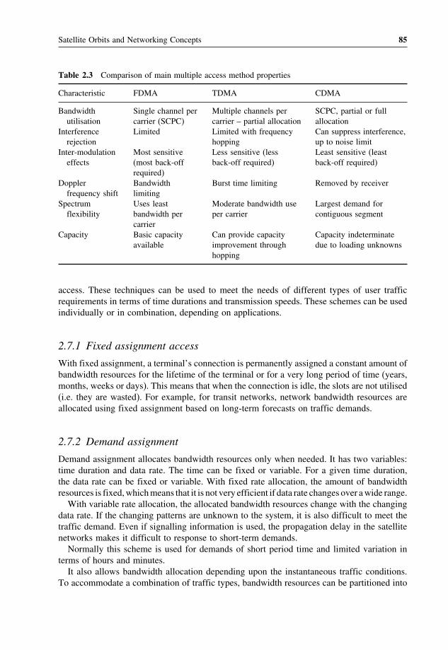
Satellite Orbits and Networking Concepts 85
Table 2.3 Comparison of main multiple access method properties
Characteristic FDMA TDMA CDMA
Bandwidthutilisation
Single channel percarrier (SCPC)
Multiple channels percarrier – partial allocation
SCPC, partial or fullallocation
Interferencerejection
Limited Limited with frequencyhopping
Can suppress interference,up to noise limit
Inter-modulationeffects
Most sensitive(most back-offrequired)
Less sensitive (lessback-off required)
Least sensitive (leastback-off required)
Dopplerfrequency shift
Bandwidthlimiting
Burst time limiting Removed by receiver
Spectrumflexibility
Uses leastbandwidth percarrier
Moderate bandwidth useper carrier
Largest demand forcontiguous segment
Capacity Basic capacityavailable
Can provide capacityimprovement throughhopping
Capacity indeterminatedue to loading unknowns
access. These techniques can be used to meet the needs of different types of user trafficrequirements in terms of time durations and transmission speeds. These schemes can be usedindividually or in combination, depending on applications.
2.7.1 Fixed assignment access
With fixed assignment, a terminal’s connection is permanently assigned a constant amount ofbandwidth resources for the lifetime of the terminal or for a very long period of time (years,months, weeks or days). This means that when the connection is idle, the slots are not utilised(i.e. they are wasted). For example, for transit networks, network bandwidth resources areallocated using fixed assignment based on long-term forecasts on traffic demands.
2.7.2 Demand assignment
Demand assignment allocates bandwidth resources only when needed. It has two variables:time duration and data rate. The time can be fixed or variable. For a given time duration,the data rate can be fixed or variable. With fixed rate allocation, the amount of bandwidthresources is fixed,whichmeans that it is not very efficient if data rate changes over awide range.With variable rate allocation, the allocated bandwidth resources change with the changing
data rate. If the changing patterns are unknown to the system, it is also difficult to meet thetraffic demand. Even if signalling information is used, the propagation delay in the satellitenetworks makes it difficult to response to short-term demands.Normally this scheme is used for demands of short period time and limited variation in
terms of hours and minutes.It also allows bandwidth allocation depending upon the instantaneous traffic conditions.
To accommodate a combination of traffic types, bandwidth resources can be partitioned into

86 Satellite Networking: Principles and Protocols
several sections, each operating under its own bandwidth allocation schemes. The systemobserves the traffic conditions and makes adjustments dynamically according to the trafficconditions. This is also called the dynamic allocation scheme or adaptive allocation scheme.
2.7.3 Random access
When bandwidth demands are very short such as a frame data bits, it becomes impracticaland there is too much overhead for any allocation scheme to make efficient use of bandwidthresources. Therefore, random access is the obvious option.It allows different terminals to transmit simultaneously. Because the transmission is very
short, the transmission has a very high success rate for low traffic load conditions. The trans-missions may collide with each other. The chance of collisions increases with the increase oftraffic load conditions. When the transmission is corrupted during transmission due to col-lision (or transmission), data has to been re-transmitted. The system also needs packet erroror loss correction by observing transmitted data or acknowledgements from the receiver.Such a scheme is based on the contention scheme. The contentions have to be resolved to
increase the chance of success. Normally if there is any collision, the transmitting terminalsback off their transmission for random period of times and increases the back-off to a longerperiod if collision occurs again until the contention is resolved. Back-off effectively reducestraffic load gradually to a reasonable operational level.Random access can achieve a reasonable throughput, but cannot give any performance
guarantees for individual terminals due to the nature of random access. Typical examples ofrandom access schemes are aloha and slotted aloha. It can also work with the other schemes.
2.8 Satellite networking issues
After discussing the connections between ground earth stations and satellites, we now discusshow to link the satellites into networks. For transparent satellites, a satellite can be consideredas a mirror ‘bending’ the link in the sky to connect ground earth stations together. Forsatellites with on-board processing (OBP) or on-board switching (OBS), a satellite can beconsidered as a node in the sky. Without losing generality, we will consider satellites asnetwork nodes in the sky.
2.8.1 Single hop satellite connections
In this type of configuration, any end-to-end connection is routed through a satellite onlyonce. Each satellite is set up as an ‘island’ to allow network nodes on the ground tobe interconnected with any other ground station via the island. The topology of satellitenetworks forms a star, where the satellite is in the centre as shown in Figure 2.25.
2.8.2 Multi-hop satellite connections
In this type of configuration, an end-to-end connection is routed through the satellitenetwork more than once, through the same satellite or different satellites. In the formercase, it is widely used in very small aperture terminal (VSAT) networks where the signal

Satellite Orbits and Networking Concepts 87
Centre of the star topology
Figure 2.25 Single hop topology with satellite at the centre
between two terminals is too weak to make a direct communication and a large groundhub is used to boost the signal between the communicating terminals. In the latter case, onehop may not be far enough to reach remote terminals, therefore more hops are used for theconnections. The topology of the satellite network forms a star with a ground hub at thecentre of the star or multiple stars where the hubs are interconnected to link the satellitestogether as shown in Figure 2.26.
Centre of the star topology
(a) Single hub and single satellite topology configuration.
(b) Multi-satellites with multi-hubs configuration.
Centres of the star topology
interconnected
Figure 2.26 Multiple hops topology with hub at the centre

88 Satellite Networking: Principles and Protocols
2.8.3 Inter-satellite links (ISL)
To reduce the earth segment of the network connections, we introduce the concept ofinter-satellite links. Without ISL, the number of ground earth stations will increase to linkmore satellites together, particularly for LEO or GEO constellations where the satellitescontinuously moving across the sky. The topology of the network also changes with themovement of the constellation.As the positions between satellites are relatively stable, we can link the satellite constella-
tions together to form a network in the sky. This allows us to access the satellite sky networkfrom the earth with fewer stations needed to link all the satellites into a network as shownin Figure 2.27.Another advantage of using ISL is that satellites can communicate directly with each other
by line of sight, hence decreasing earth–space traffic across the limited air frequencies byremoving the need for multiple earth–space hops. However, this requires more sophisticatedand complex processing/switching/routing on-board satellites to support the ISL. This allowscompletion of communications in regions where the satellite cannot see a ground gatewaystation, unlike the simple ‘bent-pipe’ satellites, which act as simple transponders.For circular orbits, fixed fore and aft ISL in the same plane have fixed relative positions.
For satellites in different orbit planes, the ISL have changing relative positions, because theline-of-sight paths between the satellites will change angle and length as the orbits separateand converge between orbit crossings, giving rise to:
• high relative velocities between the satellites;• tracking control problems as antennas must slew around; and• the Doppler shift effect.
In elliptical orbits, a satellite can see that the relative positions of satellites ‘ahead’ and‘behind’ appear to rise or fall considerably throughout the orbit, and controlled pointing ofthe fore and aft intra-plane links are required to compensate for this, whereas inter-planecross-links between quasi-stationary apogees (quasi GEO constellation) can be easier tomaintain.
Access to
satellite
networks
Figure 2.27 Satellite networks with inter-satellite links

Satellite Orbits and Networking Concepts 89
We can see that it is a trade-off between complexity in the sky or on earth, i.e. it ispossible to design a satellite constellation network without ISL, or with ISL of a very smallnumber of earth stations or a moderate number of earth stations to increase the connectivitybetween the satellite network and ground network.
2.8.4 Handovers
Whereas the handovers (also called handoffs) of communications are well understood inthe terrestrial mobile networks, the handovers in non-geostationary satellite networks addadditional complexity to satellite network designs, due to relative movements between thesatellites and between the satellites and ground earth stations.Handover is needed to keep the links from source to destination connections. Satellite
coverage moves along with the satellite and links must be handed over from one satellite tothe next satellite (inter-satellite handover). For multi-beam satellites, handover is also neededbetween spot beams (beam handover or intra-satellite handover) and eventually to the nextsatellite (inter-satellite handover) as shown in Figure 2.28. When the next beam or satellitehas no idle circuit to take over the handed-over links, the links get lost which can forcetermination of connection-oriented services; this event is referred to as a handover failure.Premature handover generally results in unnecessary handover and delayed handover resultsin increased probability of forced termination. Handover can be initiated based on the signallevel strength and/or distance measurements position.Two handover scenarios for satellite handovers are possible: intra-plane satellite handover
and inter-plane satellite handover.Intra-plane satellite handover assumes that the subscriber moves from beam to beam
within the coverage area of satellite S. The gateway knows the subscriber is approaching theboundary between satellite S and satellite T because it knows the subscriber’s location areacode and the satellite’s locations. The gateway will send a message to the trailing satelliteS to prepare to handover the subscriber and another message to the leading satellite T in thesame plane to prepare to accept the subscriber. The gateway will then send a message to the
Satellite
coverage Spot beam
coverage
Inter
satellite
Intra
satellite
Figure 2.28 Concepts of inter-satellite beam and intra-satellite beam handovers

90 Satellite Networking: Principles and Protocols
station via satellite S to resynchronise with the new satellite T. The handover is completedwhen the satellite sends a message to the station informing it of which new frequency touse. The gateway is the intelligent entity in this handover case.Inter-plane satellite handover is the same as intra-plane satellite handover except that
instead of handing over the connection to a satellite in the same orbit plane, it is handedover to a satellite in a different plane. The reason of performing a handover to a satellite inanother plane is if no satellite in the same plane is able to cover the subscriber or if thereare no available channels in the satellite of the same plane to perform a handover. Anotherreason can be that the satellite in a different plane can provide better service due to spacediversity, as lower altitude satellites have more problems with shadowing than higher altitudesatellites.The time necessary for launching and executing the handover must be very short. In
addition, the handovers should not degrade quality of service for the connections.With the satellites’ orbital velocity, and the dimension of coverage, the time to cross the
overlap area covered by satellites is relatively short. However, due to the characteristics ofthe satellite constellation, a terminal can be covered by at least two satellites. This offersthe possibility of optimising the handover, with respect to the quality of service of eachconnection, and serving a greater number of connections.With the development of terminal technologies and integration with GPS functions, it is
possible that satellite terminals will also be able to provide more assistance to the handoverprocesses.
2.8.5 Satellite intra-beam and inter-beam handovers
Beam handover has two scenarios: intra-beam handover and inter-beam handover.Intra-beam handover assumes that the subscriber is in beam A using frequency 1 and is
associated with satellite S. As the beam approaches another geographic region, frequency 1may no longer be available. There are two possible reasons for this. The first is governmentregulations, i.e. the particular set of frequencies is not available in the approaching region.Another reason is interference, which may be caused when satellite S moves too close toanother satellite using the same frequency. In this case, even though the subscriber is stillwithin beam A (satellite S), the satellite will send a message to the portable unit to changeto frequency 2 in order to maintain the communication link. The satellite is the intelligententity in this handover case.Inter-beam handover scenario allows gateway earth stations (GES) or terminal earth station
(TES) to continually monitor the radio frequency (RF) power of frequency 1 used in beamA. They also monitor the RF power of two adjacent candidate handover beams, B and C, viathe general broadcast channel (information channel). The station determines when to handover based on the RF signal strength. If the beam B signal becomes stronger than the signalused in beam A, the station will initiate a handover request to the satellite to switch the userto beam B. The satellite assigns a new frequency 3 to the station because two adjacent beamscannot use the same frequency (typically 3-, 6- and 12-beam patterns are used for efficientfrequency reuse and coverage purpose). Inter-beam handover can be extremely frequent, ifthe beams are small and/or satellites move fast. There can also be an intelligent entity inthis handover case.

Satellite Orbits and Networking Concepts 91
2.8.6 Earth fixed coverage vs. satellite fixed coverage
The handover problem is considered according to the constellation. A satellite constellationcan be designed as earth fixed coverage (EFC) or satellite fixed coverage (SFC) as shownin Figure 2.29. In EFC, each coverage area of satellite beams is fixed in relation to earth,therefore relatively it allows a longer period of time for handover. In contrast, each coveragearea of SFC is moving along the satellite, hence it is fixed in relation to the satellite butmoving in relation to earth. There is a relatively short period of time for handover, becausethe overlap between two-satellite coverage can be very small and moving away very fast.The problems that occur in EFC constellations are due to the exaggerated difference in
propagation delays in the radio signal of each satellite. The difference, due to differentsatellite locations, results in the loss of sequence, loss or duplication of coverage accordingto the position of satellites relative to earth units.The benefit of multi-beam satellites is that each satellite can serve its entire coverage area
with a number of high-gain scanning beams, each illuminating a single small area at a time.Narrow beamwidth allows efficient reuse of the spectrum and resulting high system capacity,high channel density and low transmitter power. However, if this small beam pattern sweptthe earth’s surface at the velocity of the satellite, a terminal would have a very short periodof time for communication before the next handover procedure. As in the case of terrestrialcellular systems, frequent hand-offs result in inefficient channel utilisation, high processingcosts and lower system capacity.In EFC, each satellite manages channel resources (frequencies and time slots associated
with each coverage area) in the current serving area. As long as a terminal remains within thesame earth fixed coverage, it maintains the same channel assignment for the duration of a call,regardless of how many satellites and beams are involved. Channel reassignments becomethe exception rather than the rule, thus eliminating much of the frequency management andhand-off overhead.A database contained in each satellite defines the type of service allowed within each cov-
erage area. Small fixed beams allow satellite constellations to avoid interference to or fromspecific geographic areas and to contour service areas to national boundaries. This would be
Handover
Satellite movement
Handover
Satellite movement
(a) Earth fixed coverage (EFC)
Coverage movement
(b) Satellite fixed coverage (SFC)
Figure 2.29 Satellite constellations of earth fixed coverage and satellite fixed coverage
92 Satellite Networking: Principles and Protocols
difficult to accomplish with large beams or beams that move with the satellite. Active antennasare normally used to fix the beams onto earth while the satelites are flying at high speed.
2.8.7 Routing within constellation of satellites network
In addition to ISL and links between satellites and earth stations, routing finds paths toprovide end-to-end connections by making use of the links. Clearly routing affects directlythe utilisation of the network resources and quality of service provided by the connections.The routing methods within constellations depend on the constellation design. The topol-
ogy of a LEO constellation of satellites network is dynamic. The network connectivitybetween any two points is also dynamic. The satellites move with time above a rotatingearth. Each satellite keeps the same position relative to other satellites in its orbital plane.Its position and propagation delay relative to earth terminals and to satellites in other planeschange continuously but predictably. In addition to changes in network topology, as trafficflows through the network, routes are also changing with time. All of these factors affectthe routing from source to destination of connections or packets.The maximum delay between two end points, including the hops across satellite is con-
strained by real-time propagation delays. These constraints limit the hop count in systemsutilising ISL. Satellite failure can create islands of communication within the LEO network.The network routing algorithm must accommodate these failures.Due to the satellite orbital dynamics and the changingdelays,mostLEOsystems are expected
to use some form of adaptive routing to provide end-to-end connectivity. Adaptive routinginherently introduces complexity anddelayvariation. In addition, adaptive routingmay result inpackets being out of order. These out-of-order packets will have to be reordered by the receiver.As all satellite nodes and ISLs have the same characteristics, it is convenient to separate
the satellite part and terrestrial part of the routing. This allows different routing algorithmsto be used effectively and they can be transparently adapted for the network characteristics.Routing algorithms can be distributed or centralised. In centralised routing algorithms, all
satellites report information about constellation command and control, which then calculatesrouting graphs and passes information back to the satellites for connection or packet routing.In distributed routing algorithms, all satellites exchange network metrics (such as propa-
gation delay, traffic load conditions, bandwidth availability and node failures, etc.) and eachsatellite tries to calculate its own routing graphs. QoS parameters may also be taken intoaccount, such as delay and bandwidth requirements. The routing algorithms should also beable to trade off between QoS for user applications and efficiency for network resourceutilisations.Due to the motion of the satellites and user terminals, both the start and end points of the
route may change with time and also the ISL path. Therefore satellite network routing isrelatively more complicated than terrestrial network routing.
2.8.8 Internetworking
Internetworking is the final stage for satellite networking and provides connectivity directly tothe user terminals or terrestrial networks. In addition to physical layer connections in terms ofbandwidth and transmission speed, higher layer protocols also need to be taken into account.

Satellite Orbits and Networking Concepts 93
According to possible differences between protocols used in satellite networks, terrestrialnetworks and satellite terminals, the following techniques can be used for internetworking:
• Protocol mapping is a technique used to translate the functions and packet headers betweendifferent protocols.
• Tunnelling is a technique used to treat one protocol as data to be transported in thetunnelling protocol. The tunnelled protocol is processed only at the end of the tunnel.
• Multiplexing and de-multiplexing are techniques used to multiplex several data streamsinto one stream and to de-multiplex one data stream into multiple streams.
• Traffic shaping is a technique used to shape the characteristics of traffic flows such asspeeds and timings to be accommodated by the transport network.
2.8.9 Satellite availability and diversity
The total availability of the satellite network Atotal is dependent on the availability of thesatellite Asatellite, the availability of the satellite link Apropagation and the availability ofthe satellite resources Acongestion.
Atotal = Asatellite×Apropagation×Acongestion
From a dependability point of view, a portion of a network connection should have thefollowing properties:
• The fraction of time during which it is in a down state (i.e. unable to support a connection)should be as low as possible.
• Once a connection has been established, it should have a low probability of being eitherterminated because of insufficient data transfer performance or prematurely released dueto the failure of a network component.
Availability of a network connection portion is defined as the fraction of time during whichthe connection portion is able to support a connection. Conversely, unavailability of a portionis the fraction of time during which the connection portion is unable to support a connection(i.e. it is in the down state). A common availability model is depicted in Figure 2.30.
Unavailable State (2)
Available State (1)
Unavailable State (4)
Available State (3)
Satellite Link Unavailable
Satellite Link Available
Satellite Link in use
Satellite Link not in use
Figure 2.30 Satellite network availability model

94 Satellite Networking: Principles and Protocols
The model uses four states corresponding to the combination of the ability of the networkto sustain a connection in the available state and the actual use of the connection. Twoindependent perspectives are evident from the model:
• The service perspective, where availability performance is directly associated with theperformance perceived by the user. This is represented in Figure 2.30 by states 1 and 2,even in the case of an on/off source since the user is only concerned with the connectionavailability performance while attempting to transmit packets.
• The network perspective, where availability performance is characterised independentlyof user behaviour. All four states in Figure 2.30 are applicable.
There are two availability parameters defined as the following:
• Availability ratio (AR): defined as the portion of time that the connection portion is in theavailable state over an observation period, whether the connection is in use or not.
• Mean time between outages (MTBO): defined as the average duration of a time inter-val during which the connection is available from the service perspective. Consecutiveintervals of available time during which the user attempts to use are concatenated.
Diversity is technique used to improve satellite link availability. There are different typesof diversity. Here we discuss only two types of diversity:
• Earth-to-space diversity uses more than one satellite at once for communication. Thisallows an improvement in physical availability, by decreasing the impact of shadowingdue to buildings obstructing the path between the ground terminal and satellite and byproviding redundancy at the physical or data-link level. Diversity is also exploited for softhandovers, i.e., the old connection is closed only after successful establishment of a newconnection.
• In-orbit network diversity provides redundancy for failures in links and satellites. It isonly possible due to the large number of satellites in the constellation with close spacing.
As this can affect routing across the ISL mesh, it can have a considerable effect onend-to-end delivery.
Further reading[1] Haykin, S., Communication Systems, 4th edition, John Wiley & Sons, Inc., 2001.[2] ITU, Handbook on Satellite Communications, 3rd edition, John Wiley & Sons, Inc., 2002.
Exercises
1. Use the laws of physics including Kepler’s laws and Newton’s laws to explain thefeatures of satellite orbits.
2. Use Newton’s laws to calculate GEO satellite orbit parameters.

Satellite Orbits and Networking Concepts 95
Exercises (continued)
3. Design a constellation of quasi GEO satellites to provide coverage over the NorthPole region.
4. Calculate the free-space loss of GEO satellite links.5. Explain different types of modulation techniques and why the phase shift modu-
lation technique is more suitable for satellite transmission.6. Explain the important error correction coding schemes.7. Explain how turbo code achieves performance close to the Shannon limit.8. Explain the differences between the concepts of multiple access and multiplexing.9. Explain the different bandwidth resources allocation schemes.
10. Discuss the satellite networking design issues.11. Explain the concept of quality of service (QoS) at the physical layer in terms of
bit error rate (BER) and the techniques to improve QoS.12. Explain the quality of satellite networking in terms of availability and the tech-
niques used to improve satellite availability.


3ATM and Internet Protocols
This chapter aims to provide an introduction to the ATM and Internet protocols in the contextof the basic protocol layering principles. It discusses internetworking between the ATM andInternet networks. It also provides the basic knowledge to help readers better understand thefollowing chapters on satellite internetworking with terrestrial networks, ATM over satelliteand Internet over satellite. When you have completed this chapter, you should be able to:
• Understand the concepts of ATM protocol and technology.• Identify the functions of ATM adaptation layers (AAL) and the type of services theyprovide.
• Describe how ATM cells can be transported by different physical layer transmissions.• Know the ATM interfaces and networks.• Explain the relationships between traffic management, quality of service (QoS) and trafficpolicing functions.
• Describe the generic cell rate algorithm (GCRA).• Knows the functions of the Internet protocol (IP).• Understand the transmission control protocol (TCP) and user datagram protocol (UDP)and their use.
• Appreciate the concepts of internetworking between Internet and ATM.
3.1 ATM protocol and fundamental concepts
ATM is a fast packet-oriented transfer mode based on asynchronous time division multiplex-ing and it uses fixed-length (53 bytes) cells, each of which consists of an information field(48 bytes) and a header (5 bytes) as shown in Figure 3.1. The header is used to identify cellsbelonging to the same virtual channel and thus used in appropriate routings. Cell sequenceintegrity is preserved per virtual channel.
Satellite Networking: Principles and Protocols Zhili Sun© 2005 John Wiley & Sons, Ltd

98 Satellite Networking: Principles and Protocols
5 Octets
Payload
48 Octets
Header
Figure 3.1 ATM cell
The B-ISDN protocol reference model consists of three planes: user plane for transportinguser information; control plane responsible for call control, connection control functions andsignalling information; and management plane for layer management functions and planemanagement functions. There is no defined (or standardised) relationship between OSI layersand B-ISDN ATM protocol model layers, however, the following relations can be found.The physical layer of ATM is almost equivalent to layer 1 of the OSI model and it performsbit-level functions.The ATM layer is equivalent to the upper layer 2 and lower layer 3 of the OSI model.
The ATM adaptation layer performs the adaptation of OSI higher layer protocols. Figure 3.2illustrates the hierarchy of the ATM protocol stack.
Higher Layer Functions
Convergence Sublayer
Generic Flow ControlCell header generation/extractionCell VPI/VCI TranslationCell Multiplexing and Demultiplexing
Cell rate decouplingHEC header generation/verificationCell delineationTransmission frame adaptionTransmission frame generation/recovery
Segmentation and Reassembly
Bit timingPhysical Media
CS
SAR
AAL
ATM
PhysicalLayer
TC
PM
Figure 3.2 Functions of the ATM protocol stack
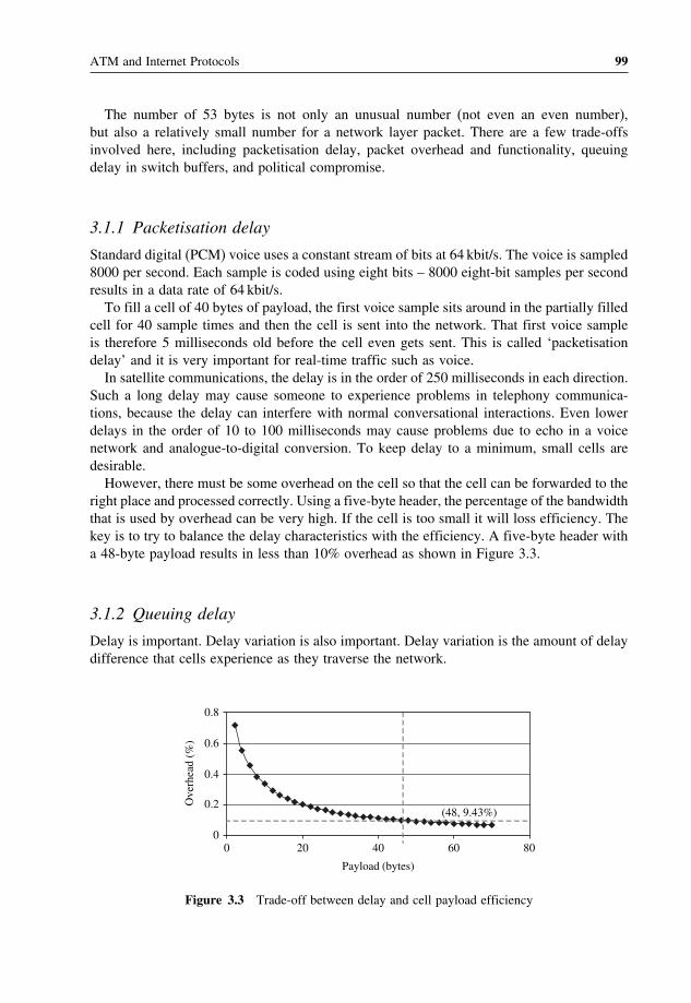
ATM and Internet Protocols 99
The number of 53 bytes is not only an unusual number (not even an even number),but also a relatively small number for a network layer packet. There are a few trade-offsinvolved here, including packetisation delay, packet overhead and functionality, queuingdelay in switch buffers, and political compromise.
3.1.1 Packetisation delay
Standard digital (PCM) voice uses a constant stream of bits at 64 kbit/s. The voice is sampled8000 per second. Each sample is coded using eight bits – 8000 eight-bit samples per secondresults in a data rate of 64 kbit/s.To fill a cell of 40 bytes of payload, the first voice sample sits around in the partially filled
cell for 40 sample times and then the cell is sent into the network. That first voice sampleis therefore 5 milliseconds old before the cell even gets sent. This is called ‘packetisationdelay’ and it is very important for real-time traffic such as voice.In satellite communications, the delay is in the order of 250 milliseconds in each direction.
Such a long delay may cause someone to experience problems in telephony communica-tions, because the delay can interfere with normal conversational interactions. Even lowerdelays in the order of 10 to 100 milliseconds may cause problems due to echo in a voicenetwork and analogue-to-digital conversion. To keep delay to a minimum, small cells aredesirable.However, there must be some overhead on the cell so that the cell can be forwarded to the
right place and processed correctly. Using a five-byte header, the percentage of the bandwidththat is used by overhead can be very high. If the cell is too small it will loss efficiency. Thekey is to try to balance the delay characteristics with the efficiency. A five-byte header witha 48-byte payload results in less than 10% overhead as shown in Figure 3.3.
3.1.2 Queuing delay
Delay is important. Delay variation is also important. Delay variation is the amount of delaydifference that cells experience as they traverse the network.
00 20 40 60 80
0.2
0.4
0.6
0.8
Payload (bytes)
Ove
rhea
d (%
)
(48, 9.43%)
Figure 3.3 Trade-off between delay and cell payload efficiency

100 Satellite Networking: Principles and Protocols
0
2
4
6
8
10
0 20 40 60 80
Payload (bytes)
Del
ay (
ms)
(48, 6.833)
Figure 3.4 Delay due to packetisation and queuing
For example, consider a high-speed link with a 100-byte message to be transmitted.Further assume that this link is shared with 100 other streams of data. The best case forqueuing delay is that there is no other data to send when the message arrives. Just send it,and effectively the queuing is almost zero. The worst case would be to wait for each of theother 100 streams to send their 100-byte message first.Consider this worst case. If the payload is very small, one has to send so many cells that
efficiency is quite poor as shown in Figure 3.4. If the cells is too large, the amount of timeyou have to wait for all these other cells to go, increases.When the cells become bigger and bigger, the time to wait for a cell before one can get
access to the link goes up, and it essentially goes up linearly. It can be seen that small cellsizes can have a large delay due to a large number of cells need to process, and delay willalso become large if the payload becomes large as it takes time to process large cell.
3.1.3 Compromise solution between North America and Europe
Naturally, the important question of picking a cell size involves extensive analysis oftechnical concerns. In Europe, in fact, one of the major concerns was the packetisationdelay because Europe consists of many small countries hence distance is small within eachof the telephone networks. Thus, they do not need to deploy very much echo cancellationtechnology.In North America, the distance within the countries is large, causing telephone companies
to deploy echo cancellation technology. Thus, North Americans generally favoured a largecell with 64 octets of payload and a five-octet header, while Europeans generally favoureda smaller cell of 32 octets of payload and a four-octet header. One of the big differenceswas the concern about how to handle voice, since telephony services generate the revenueand major traffic in the telecommunication networks.A political compromise was made, resulting in 48 octets for the payload with intensive
averaging between 64 and 32 octets. Of course, this turned out to be too large to avoid the useof echo cancellers while failing to preserve the efficiency of 64 octets. Since Internet trafficexceeds telephony traffic, the size of the ATM cell is not important any more, however, theprinciples used to achieve optimisation and compromise to be acceptable at a global scalestill are.

ATM and Internet Protocols 101
3.2 ATM layer
The ATM layer is the core of the ATM protocol stack. There are two different forms ofheader format for an ATM cell: one for the user network interface (UNI) between userterminal equipment and network node inter connections and the other for the network nodeinterface (NNI) as illustrated in Figure 3.5.
3.2.1 The GFC field
The generic flow control (GFC) field occupies the first four bits in the header. It is onlydefined on in the UNI. It is not used in the NNI, which is the interface between switches.The GFC field can be used for flow control or for building a multiple access so that thenetwork can control ATM cell flows from user terminals into the network.
3.2.2 The VPI and VCI fields
The important fields for routing in the header are the virtual path identifier (VPI) and virtualchannel identifier (VCI) fields. A number of virtual connections through an ATM switch areshown in Figure 3.6. Within the switch, there has to be a connection table (or routing table)and that connection table associates a VPI/VCI and port number with another port numberand another VPI/VCI.When a cell comes into the switch, the switch looks up the value of the VPI/VCI from
the header. Assume that the incoming VPI/VCI is 0/37. Because the cell came in on portone, the switch looks in the port one entries and discovers that this cell has to go to portthree. When being sent out on port three, the VPI/VCI value is changed to 0/76, but theinformation content remains the same.The VPI/VCI values change for two reasons. First, if the values were unique, there would
only be about 17 million different values for use. As networks get very large, 17 millionconnections will not be enough for an entire network. Second, it is impossible to guaranteethat in each newly established connection has a unique value in the world.
GFC
CLPPTVCI
VCI
VPI
VPI VCI
HEC
1
1 2 3 4 5 6 7 8 1 2 3 4 5 6 7 8
2
3
4
5
at the UNI
CLPPTVCI
VCI
VPI
VPI VCI
HEC
at the NNI
Figure 3.5 The ATM cell header format at the UNI and NNI

102 Satellite Networking: Principles and Protocols
ATMSwitch
In port
0/371
0/421
0/372
0/782
3
4
5
6
Out Port VPI/VCI
0/76
0/88
0/52
0/22
37 42
37 78
1
2
3
4
5
6
76
88
52
22
Connection/Routing Table
VPI/VCI
Figure 3.6 Connection/routing table in ATM switch
It is interesting to note that both of these considerations are becoming quite important inthe Internet, where a limited number of TCP/IP addresses are available. If the address spacewere made large enough to serve as universal addresses, the overhead in comparison to thepayload in the cell would become unacceptable.Consequently, the VPI/VCI value is only meaningful in the context of the given interface.
In fact, in this example ‘37’ is used on in both interfaces, however, but there is no ambiguitybecause they are considered in the context of different physical interfaces. There is a separateentry for 37 for port two, which of course goes to a different destination.So the combination of the VPI/VCI values allows the network to associate a given cell
with a given connection, and therefore it can be routed to the right destination. The idea tohave two values to identify a channel within the physical layer is illustrated in Figure 3.7.A virtual path is a bundle of virtual channels. The VPI is eight bits, providing up to 256different bundles. Of course, the individual virtual channels have unique VCI values, but theVCI values may be reused in different virtual paths.
Physical LayerVirtual Path ( VP)
Virtual Channel ( VC)
Figure 3.7 Concept of VP and VC in physical layer

ATM and Internet Protocols 103
VP switching
VPI 1
VPI 2
VPI 3
VPI 4
VPI 5
VPI 6
VCI 1
VCI 2
VCI 1
VCI 2
VCI 3
VCI 4
VCI 5
VCI 6
VCI 3
VCI 4
VCI 5
VCI 6
Figure 3.8 Example of VP switching
VC switch
Endpointof VPC
V
VC and VP switching
VP switch
Figure 3.9 Example of VC and VP switching
ATM allows two different ways of getting connections to an ATM network shown inFigures 3.8 and 3.9. These two figures show how the network can support a ‘bundle’of connections and how to switch the ‘bundle’ of connections and individual connectionwithin it.
3.2.3 The CLP field
By default the one-bit cell loss priority (CLP) field is set as 0 as high priority. Cellswith this bit set to 1 should be discarded before cells that have the bit set to 0. Considerreasons that why cells may be marked as expendable. First, this may be set this by theterminal. This may be desirable if, for example, in a wide area network (WAN) with aprice drop for these low-priority cells. This could also be used to set a kind of priorityfor different types of traffic when one were aware to over use a committed service level.The ATM network can also set this bit for traffic management purposes in the trafficcontract.

104 Satellite Networking: Principles and Protocols
3.2.4 The PT field
The payload type (PT) identifier has three bits in it. The first bit is used to distinguish datacells from cells of operation, administration and maintenance (OMA). The second bit iscalled the congestion experience bit. This bit is set if a cell passes through a point in thenetwork that is experiencing congestion, this bit is set. The third bit is carried transparentlyby the network. Currently, its only defined use is in one of the ATM adaptation layer type5 (AAL5) for carrying IP packets.
3.2.5 The HEC field
The last eight-bit header error check (HEC) field is needed because if a cell is going througha network and the VPI/VCI values have errors, it will be delivered to the wrong place. Asa security issue, it was deemed useful to put some error checking on the header. Of course,the HEC is also used, depending on the physical medium, e.g. in SONET, to delineate thecell boundaries.HEC actually has two modes. One is a detection mode where if there is an error with
the CRC calculation, the cell is discarded. The other mode allows the correction of one-biterrors. Whether one or the other mode is used depends on the actual medium in use. Iffibre optics is used, one-bit error correction may make a lot of sense because typically theerrors are isolated. It may not be the right thing to do if errors tend to come in bursts in themedium, such as copper and wireless link. When one-bit error correction is used, it increasesthe risk of a multiple-bit error being interpreted as a single-bit error, mistakenly ‘corrected’and sent someplace. So the error detection capabilities drop when the correction mode isused.Notice that the HEC is recalculated link by link because it covers the VPI and VCI values
which change as ATM cells are transported through the network.
3.3 ATM adaptation layer (AAL)
AAL is divided into two sublayers as shown in Figure 3.2: segmentation and reassembly(SAR) and convergence sublayers (CS).
• SAR sublayer: this layer performs segmentation of the higher layer information into a sizesuitable for the payload of the ATM cells of a virtual connection, and at the receive side itreassembles the contents of the cells of a virtual connection into data units to be deliveredto the higher layers.
• CS sublayer: this layer performs functions like message identification and time/clockrecovery. It is further divided into a common part convergence sublayer (CPCS) and aservice-specific convergence sublayer (SSCS) to support data transport over ATM. AALservice data units are transported from one AAL service access point (SAP) to one or moreothers through the ATM network. The AAL users can select a given AAL-SAP associatedwith the QoS required to transport the AAL-SDU. Five AALs have been defined, one foreach class of service.

ATM and Internet Protocols 105
Timingrelation
Bit rate
Connectionmode
Class A Class B Class C Class D
required not required
constant variable
connection-oriented connection-less
Examples: A - Circuit emulation, CBR VideoB - VBR video and audioC - CO data transferD - CL data transfer
Figure 3.10 Service classes and their attributes
The role of the AAL is to define how to put the information of different types of servicesinto the ATM cell payload. The services and applications are different and therefore requiredifferent types of AAL. It is important to know what kinds of services are required.Figure 3.10 illustrates the results of the ITU-T’s efforts for defining service classes.
• Class A has the following attributes: end-to-end timing, constant bit rate and connec-tion oriented. Thus, Class A emulates a circuit connection on top of ATM. This is veryimportant for initial multimedia applications because virtually all methods and technolo-gies today that carry video and voice assume a circuit network connection. Taking thistechnology and moving it into ATM requires a supporting circuit emulation service (CES).
• Class B is similar to class A except that it has a variable bit rate. This might be perfomingvideo encoding but not playing at a constant bit rate. The variable bit rate really takesadvantage of the burst nature of the original traffic.
• Classes C and D have no end-to-end timing and have variable bit rates. They are orientedtoward data communications, and the only difference between the two is connection-oriented versus connection-less.
3.3.1 AAL1 for class A
Figure 3.11 shows AAL type 1 (AAL1) for Class A, illustrating the use of the 48-bytepayload. One byte of the payload must be used for this protocol.Convergence sublayer indication (CSI) consists of one bit. It indicates the existence of an
eight-bit pointer if CSI = 1 and no existence if CSI = 0. Sequence number (SN) can be used
Payload
4 bits 47 or 46 bytes
SNPCSI SN
1 3 bits
Pointer(optional)
8 bits
Figure 3.11 AAL 1 packet format for Class A

106 Satellite Networking: Principles and Protocols
for cell loss detection and providing time stamps using adaptive clock methods. Sequencenumber protection (SNP) protects the CN by using CRC.There are a number of functions here, including detecting lost cells and providing time
stamps to support a common clock between the two end systems. It is also possible that thisheader could be used to identify byte boundaries by emulating a connection and identifyingsubchannels within the connection.The primary objective for the adaptive clock method is to obtain clock agreement, making
sure to be able to play out the original information stream. For example, in a 64 kbit/s voiceservice, the transmitter collects voice samples, fills up cells and sends those cells into thenetwork at about once every 5.875 milliseconds (transmits 47 octets at a speed of one octetevery 125 microseconds). The receiver is shown in Figure 3.12. The receiver plays out theoriginal bit stream at 64 kbit/s. This is where we see the impact of variation and delay.Using the adaptive clock method, the receiver establishes a buffer based on the character-
istics of the connection at 64 kbits. It establishes a watermark and then collects some cellsup to about the watermark. Then the receiver unwrap the bits from the payload and playsthem out as a stream of bits at 64 kbit/s.If the play out is too fast, the buffer becomes empty because the cells will be arriving a
little bit too slow compared to rate of emptying them. Thus, we will have a buffer starvationproblem. If it is a little bit too slow, the buffer will start to fill, and eventually it will overrunthe buffer. Then cells get lost. The solution is that the receiver observes the fill of the bufferrelative to the watermark. If it starts to get empty, it slows the (output) clock down becausethe clock is going a little fast. If it starts to get too full, it speeds the (output) clock up.This way, the receiver’s output clock rate stays centred around the transmitter’s clock.The size of the buffer must be a function of how variable the arrival rate is for the cells.
If the cells arrive in bursts, a large buffer is required. The larger the burst is the larger thebuffer size is required. There is a lot of delay variation when the cells traverse the network.Bigger buffers also cause a larger delay. Cell delay variation (CDV) is a very importantfactor in QoS, thus it is an important parameter in traffic management.Another important factor is the effect of losing a cell. Part of the protocol is a sequence
number, which is not meant to maintain the sequence of the cells, but to detect loss. If a cellis lost, the receiver should detect the loss and essentially put in a substitute cell. Otherwise,the clock rate becomes unstable.
Received cells
Substitutecells
Speed upbit clock
Slow downbit clock
Watermark
Continuousbit stream
Figure 3.12 Illustration of adaptive clock method

ATM and Internet Protocols 107
It is interesting to note that with this kind of scheme, we can maintain a circuit-likeconnection of virtually any speed over ATM. As it is so important in supporting telephonyservice, AAL 1 is called a telephony circuit emulator.
3.3.2 AAL2 for class B
AAL type 2 (AAL2) is being defined for Class B, but it is not fully developed. This AAL isimportant, because it will allow ATM to support the burst nature of traffic to be exploitedfor packet voice, packet video, etc. Figure 3.13 illustrates the functions and frame format ofthe AAL2.
3.3.3 AAL3/4 for classes C and D
In AAL type 3/4 (AAL3/4), the protocol puts a header before and a trail after the original data,then the information is chopped into 44-byte chunks. The cell payloads include two bytesof header and two bytes of trailer, so this whole construct is exactly 48 bytes. Figure 3.14illustrates the functions and frame format of the AAL3/4.The header functions include the common part identifier (CPI) field of one byte, which
identifies the type of traffic and certain values that are to be implemented in the other fieldsof the headers and trailers. The beginning tag (Btag) field of one byte is used to identify allthe data associated with this session. The buffer allocation size (BAsize) of two bytes definesthe size of the buffer in the receiver for the data. The alignment field (AL) is filler to 32-bitalign the trailer. The end tag (Etag) is used with the Btag in the header to correlate all trafficassociated with the payload. The length field specifies the length of the payload in bytes.Note that there is a CRC check on each cell to check for bit errors. There is also an MID
(message ID). The MID allows the multiplexing and interleaving of large packets on a singlevirtual channel. This is useful when the cost of a connection is very expensive since it helpsto guarantee high utilisation of that connection.
3.3.4 AAL5 for Internet protocol
The other data-oriented adaptation layer is AAL type 5 (AAL5). It was designed particularlyfor carrying IP packet using the full 48 bytes of the ATM payload. Here, the CRC isappended at the end and the padding is such that this whole construct is exactly an integralnumber of 48-byte chunks. This fits exactly into an integral number of cells, so the construct
PayloadIT
48 bytes
SN CRCLI
1 byte 2 bytes
Figure 3.13 AAL 2 packet format for Class B

108 Satellite Networking: Principles and Protocols
H ead e r
2 4 10 bits 6 10 bits
3
44 bytes
Data
Trailer
4 bytes
0 - 65535 bytes
CRCUser Data MIDSNST LI
User DataSNST MID CRCLI
CPI BTag BAsize AL ETag Length
SNST MID CRCLIPADLast part ofUser Data
Figure 3.14 AAL 3/4 packet format for Classes C & D
48 bytes of data per cellUse PTI bit to indicate last cellOnly one packet at a time on a virtual connection
0 User Data
48
Data
0 -65535 bytes
0 User Data
48
1
48
PAD
Last cell flag
0-47
0 LE
CRC
2 2 bytes
Error Detection Fields
2
N
Figure 3.15 AAL 5 format for Internet protocol
is broken up into 48-byte chunks and put into cells. Figure 3.15 illustrates the functions andframe format of the AAL5.To determine when to reassemble and when to stop reassembling, remember the third bit
for PT in the ATM header. This bit is zero except for the last cell in the packet (when it isone).A receiver reassembles the cells by looking at the VPI/VCI and, for a given VPI/VCI,
reassembles them into the larger packet. This means that a single VPI/VCI may supportonly one large packet at a time. Multiple conversations may not be interleaved on a givenconnection. This is attractive when connections are cheap.

ATM and Internet Protocols 109
3.4 The physical layer
The first requirement for interpretability of the terminal equipment with the ATM networkand network nodes with network nodes within the network is to transmit information suc-cessfully at the physical level over physical media including fibre, twisted pairs, coaxialcable, terrestrial wireless and satellite links.As shown in Figure 3.2 the physical layer (PL) is divided into two sublayers: the physical
medium (PM) and transmission convergence (TC) sublayers.
3.4.1 The physical medium (PM) sublayers
The PM sublayer contains only the PM-dependent functions (such as bit encoding, thecharacteristics of connectors, the property of the transmission media, etc.). It provides bittransmission capability including bit alignment, and performs line coding and also conver-sions of electrical, optical and radio signals if necessary. Optical fibre has been chosen as thephysical medium for the ATM and coaxial and twisted pair cables and radio wireless linksincluding satellite can also be used. It includes bit-timing functions such as the generationand reception of waveforms suitable for the medium and also insertion and extraction ofbit-timing information.
3.4.2 The transmission convergence (TC) sublayer
In an ATM network, a terminal needs to have a cell to send data into the network. To keepthe network receiving ATM cells correctly, the terminal still has to send an ‘empty’ cellinto the network if there is nothing to send, because the ATM also makes use of the featuresof the HEC field and fixed size of the ATM cells for framing. One of the functions of theTC sublayer is to insert empty cells for transmission and remove empty cells when they getto the destination in order to keep the cell streams constant.Because of the different kinds of details in the coupling between the fibre and other
physical media, the TC sublayer differs, depending on the physical layer transmission of theATM cells. The TC sublayer mainly has five functions as shown in Figure 3.2.
• The lowest function is generation and recovery of the transmission frame.• The next function, i.e. transmission frame adaptation, takes care of all actions adaptingcell flow according to the used payload structure of the transmission system in thesending direction. It extracts the cell flow from the transmission frame in the receivingdirection. The frame can be a synchronous digital hierarchy (SDH) envelope or an envelopeaccording to ITU-T Recommendation G.703.
• The cell delineation function enables the receiver to recover the cell boundaries from astream of bits. Scrambling and descrambling are performed in the information field of acell before the transmission and after reception respectively to protect the cell delineationmechanism.
• The HEC sequence generation is performed in the transmit direction and its value isrecalculated and compared with the received value and thus used in correcting the headererrors. If the header errors cannot be corrected, the cell is discarded.
• Cell-rate decoupling inserts the idle cells in the transmitting direction in order to adapt therate of the ATM cells to the payload capacity of the transmission system. It suppresses

110 Satellite Networking: Principles and Protocols
all idle cells in the receiving direction. Only assigned and unassigned cells are passed tothe ATM layer.
3.4.3 ATM cell transmissions
As the ATM is a protocol defining an asynchronous mode, the ATM cells have to betransmitted over network technologies. In the ITU-T I-series standards, a target solutionand evolutional solution are defined for public ATM networks at transmission speeds of155.520Mbit/s or higher. For lower bit rates, the ATM Forum defined transmission methodsover existing standard transmission technologies. The ITU-T is responsible for public ATMnetwork specifications. The ATM Forum is not an international standardisation organisation.It is an international non-profit organisation, formed in 1991, with the objective of acceler-ating the use of ATM products and services through a rapid convergence of interoperabilityspecifications, and promotes industry cooperation and awareness. It is responsible for privateATM network specifications by adopting the ITU-T ATM standards if available or proposingone if not available.
3.4.4 Target solution for ATM transmission
Figure 3.16 shows the target solution recommended by the ITU-T I-series standards. Itsuggested a new transmission scheme at the physical layer so that the physical layer transmitsATM cells directly, but only provides 26/27 ATM cells to the ATM layer so that the 1/27cell can be used for supporting operation, management and administration (OMA) functions.The choice of the 1/27 cell used for OMA is to make the new scheme compatible withevolutional approaches using the SDH standards for ATM cell transmissions. The physicallayer transmission is 155.520Mbit/s, which is the same as the SDH standards physical layertransmission speed. The ATM layer is 149.760Mbit/s, which is the same as the SDH payload.
3.4.5 ATM over synchronous digital hierarchy (SDH)
The ITU-T defined the evolutional approach to transmit ATM cells over SDH before thefuture target solution. The essential feature of SDH is to keep track of boundaries of streams
1 2 26 28
1 2 26 27 28
29
OMA Cell
ATM layer: 149.760 Mbit/s
Physical Layer: 155.520 Mbit/s
27
Figure 3.16 The ITU-T target solution for ATM cell transmission

ATM and Internet Protocols 111
270 bytes
11
2
3
4
5
6
7
8
9
Sectionoverhead
AU ptr
Sectionoverhead
9 10 270
9 bytes
125 microseconds
STM-1 Payload
J1
B3
C2
G1
F2
H4
Z3
Z4
Z5
VC-4
POH
ATM Cells
Figure 3.17 SDH STM-1 frame
that do not really depend on the particular medium. Although it was originally designed fortransmission over fibre, it can in fact operate over other media.The SDH mode type 1 (STM-1) frame is compatible to the synchronous optical network
(SONET) synchronous transport signal optical carrier 3 (STS-3C) frame at 155Mbit/s asshown in Figure 3.17. The bytes are transmitted across the medium a row at a time, wrappingto the next row. It takes nominally 125 microseconds to transmit all nine rows forming theSDH STM-1 frame.The first nine bytes of each row have various overhead functions. For example, the first
two bytes are used to identify the beginning of the frame so that the receiver can lock ontothis frame.In addition, although not shown here, there is another column of bytes included in the
‘synchronous payload envelope’, which is additional overhead, with the result that each rowhas 260 bytes of information. Consequently, 260 bytes per row × 9 rows × 8 bits dividedby 125 microseconds, equals 149.76Mbit/s of payload, which is the same as the targetsolution.The STM-1 in the international carrier networks will be the smallest package avail-
able in terms of the SDH. The bit rates for SDH STM-4 are four times the bit rates ofthe STM-1.SDH also has some nice features for getting to higher rates – like 622Mbit/s – it becomes
basically a recipe of taking four of these STM-1 structures and simply interleaving the bytesto get to 622Mbit/s (STM-4). There are additional steps up to 1.2 gigabits, 2.4 gigabits,etc. And at least in theory, the recipe makes it simple to get to a speed interface from lowspeed ones.Using the header error check (HEC) of the ATM cell delineates the cells within the SDH
payload (VC-4 container). The receiver, when it is trying to find the cell boundaries, takesfive bytes to check if they form a header or not. It does the HEC calculation on the firstfour bytes and matches that calculation against the fifth byte. If it matches, the receiver then
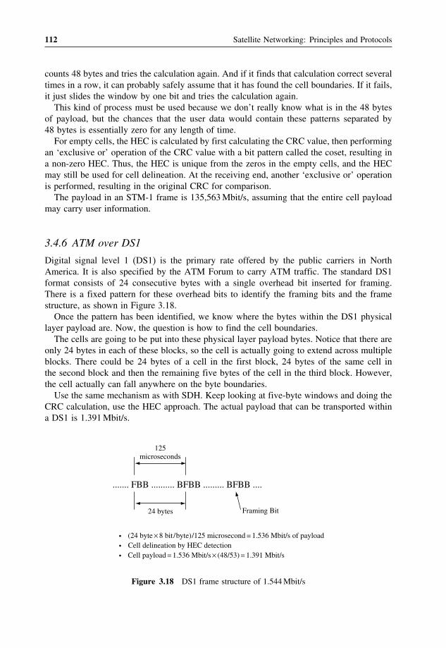
112 Satellite Networking: Principles and Protocols
counts 48 bytes and tries the calculation again. And if it finds that calculation correct severaltimes in a row, it can probably safely assume that it has found the cell boundaries. If it fails,it just slides the window by one bit and tries the calculation again.This kind of process must be used because we don’t really know what is in the 48 bytes
of payload, but the chances that the user data would contain these patterns separated by48 bytes is essentially zero for any length of time.For empty cells, the HEC is calculated by first calculating the CRC value, then performing
an ‘exclusive or’ operation of the CRC value with a bit pattern called the coset, resulting ina non-zero HEC. Thus, the HEC is unique from the zeros in the empty cells, and the HECmay still be used for cell delineation. At the receiving end, another ‘exclusive or’ operationis performed, resulting in the original CRC for comparison.The payload in an STM-1 frame is 135,563Mbit/s, assuming that the entire cell payload
may carry user information.
3.4.6 ATM over DS1
Digital signal level 1 (DS1) is the primary rate offered by the public carriers in NorthAmerica. It is also specified by the ATM Forum to carry ATM traffic. The standard DS1format consists of 24 consecutive bytes with a single overhead bit inserted for framing.There is a fixed pattern for these overhead bits to identify the framing bits and the framestructure, as shown in Figure 3.18.Once the pattern has been identified, we know where the bytes within the DS1 physical
layer payload are. Now, the question is how to find the cell boundaries.The cells are going to be put into these physical layer payload bytes. Notice that there are
only 24 bytes in each of these blocks, so the cell is actually going to extend across multipleblocks. There could be 24 bytes of a cell in the first block, 24 bytes of the same cell inthe second block and then the remaining five bytes of the cell in the third block. However,the cell actually can fall anywhere on the byte boundaries.Use the same mechanism as with SDH. Keep looking at five-byte windows and doing the
CRC calculation, use the HEC approach. The actual payload that can be transported withina DS1 is 1.391Mbit/s.
....... FBB .......... BFBB ......... BFBB ....
125microseconds
24 bytes Framing Bit
· (24 byte × 8 bit / byte) /125 microsecond = 1.536 Mbit/s of payload
· Cell delineation by HEC detection
· Cell payload = 1.536 Mbit/s × (48/53) = 1.391 Mbit/s
Figure 3.18 DS1 frame structure of 1.544Mbit/s

ATM and Internet Protocols 113
FBBBBBBBBBBBBBBBFBBBBBBBBBBBBBBB
32 Bytes / 125 microseconds
B: Cell carrying bytes F: Framing and overhead byte
· Cell delineation by HEC detection· (32 × 8) /125 microsecond = 2.048 Mbit / s of payload
161 31 byte
Figure 3.19 E1 frame structure of 2.048Mbit/s
3.4.7 ATM over E1
The 2.048Mbit/s interface will be particularly important in Europe, where this speed (E1)is the functional equivalent of North American DS1 interfaces. Note that in contrast to theDS1 format, there are no extra framing bits added. In fact, the 2.048Mbit/s rate is an exactmultiple of 64 kbit/s.The basic E1 frame consists of a collection of 32 bytes, recurring every 125 microseconds.
Instead of using framing bits, this format uses the first (Byte 0) and seventeenth (Byte 16) forframing and other control information. The receiver uses the information within the framingbytes to detect the boundaries of the physical layer blocks, or frames. The remaining 30bytes are used to carry ATM cells. Consequently, the physical layer payload capacity forthe E1 interface is 1.920Mbit/s (see Figure 3.19).Just as in SDH and DS1, as previously discussed, the HEC is used to find the cell
boundaries.
3.5 ATM interfaces and ATM networking
ATM provides a well-defined interface for networking purposes between users and network,between network nodes (switches), and between networks.
3.5.1 User–network access
Two elements can be used to describe a reference configuration of the user–network accessof B-ISDN: functional groups and reference points. Figure 3.20 gives the reference config-uration. The B-NT1 and B-NT2 are broadband network terminators. The B-NT2 providesan interface allowing other type of TE rather than the broadband TE to be connected to thebroadband network.B-NT1 functions are similar to layer 1 of the OSI reference model and some of the
functions are:
• line transmission termination;• transmission interface handling; and• OAM functions.

114 Satellite Networking: Principles and Protocols
B-NT 1B-NT 2
B-TE 1SB
TB
B-TATE 2
orB-TE 2
SBR
TES
Reference point
Functional group
Figure 3.20 B-ISDN reference configuration
B-NT2 functions are similar to layer 1 and higher layers of the OSI model. Some functionsof B-NT2 are:
• adaptation functions for different interface media and topology;• multiplexing and de-multiplexing and concentration of traffic;• buffering of ATM cells;• resource allocation and usage parameter control;• signalling protocol handling;• interface handling;• switching of internal connections.
B-TE1 and B-TE2 are broadband terminal equipment. B-TE1 can be connected directlyto the network from the reference SB and TB. B-TE2 can only be connected to the networkvia a broadband adapter.B-TA is broadband terminal adapter. It allows the B-TE2, which cannot be connected
directly, to be connected to the broadband network.SB and TB indicate reference points between the terminal and the B-NT2 and between
B-NT2 and B-NT1 respectively. Reference point characteristics are:
• TB and SB: 155.520 and 622.080Mbit/s;• R: allow connection of a TE2 or a B-TE2 terminal.
3.5.2 Network node interconnections
In Figure 3.21, first consider the private ATM network in the upper left corner. The interfacebetween the terminal and the switch is referred to as the private user-to-network interface(UNI). The interface to the public network is a public UNI. Now, these two interfacesare quite similar. For example, the cell size is the same; the cell format is the same. Thereare some differences, though. For example, the public UNI interface is likely to be a DS3interface early on, but it’s very unlikely that a DS3 would be deployed across campus.Consequently, there are some differences at the physical layer.

ATM and Internet Protocols 115
ATMSwitch
ATMSwitch
PrivateUNI
Terminal
Terminal
ATMSwitch
ATMSwitch
ATMSwitch
PublicNNI
MetropolisData ServiceInc.
ATMSwitch
ATMSwitch
ATMSwitch
PublicNNI
CountryWide Carrier
Services
Terminal
Terminal
ATMDXI
PublicUNI
B-ICI
PrivateNNI
Figure 3.21 ATM interfaces network nodes interconnections
Within a private ATM network, there is the issue of connecting multiple switches togetherinto an ATM network. This is referred to as the network node interface (NNI). In someways, the NNI is misnamed because it is really more than an interface. It is a protocol thatallows multiple devices to be interconnected in somewhat arbitrary topologies and still workas one single network.There is a corresponding protocol in the public arena called the public NNI. It has basically
the same function, but, because of the context of the problem that is being addressed, it endsup in detail to be quite different.The ATM Forum specifies the private NNI (PNNI) protocol. The ITU specifies the public
NNI. One of the major differences is that in the case of the public NNI, there is a strongdependence on the signalling network.The B-ICI specifies how two carriers can use ATM technology to multiplex multiple
services onto one link, thereby exchanging information and cooperating to offer services.
3.5.3 ATM DXI
The ATM data exchange interface (DXI) allows a piece of existing equipment – in this case,a router – to access the ATM network without having to make a hardware change. Thehardware impact is in a separate channel service unit/data service unit (CSU/DSU).

116 Satellite Networking: Principles and Protocols
Typical physical layers for the DXI are e.g. V35 or the high-speed serial interface (HSSI).Since this is a data-oriented interface, the frames are carried in HDLC frames. All thatis required is a software change in the router and the CSU-DSU to perform the ‘slicing’segmentation and reassembly (SAR) function.The CSU-DSU takes the frames, chops them up into cells, does traffic shaping if required
by the traffic contract, and ends up with a UNI.
3.5.4 B-ICI
The broadband inter-carrier interface (B-ICI), in its initial version, is a multiplexing tech-nique. It specifies how two carriers can use ATM technology to multiplex multiple servicesonto one link, thereby exchanging information and cooperating to offer services.The services specified in the B-ICI are: cell relay service, circuit emulation service, frame
relay and SMDS. Users of the carrier network don’t ‘see’ this interface, but it is importantbecause it will help provide services across carriers.
3.5.5 Permanent virtual connections vs. switched virtual connections
The connections involve routing through a switch only. How to get a connection establishedthrough a network?One technique is called a permanent virtual connection (PVC). This will be done through
some form of service order process. Conceptually, there is some sort of network managementsystem that communicates to the various devices what the VCI-VPI values are and what thetranslations are. For example, the network management system tells the switch what entriesto make in its connection table.There are some environments for which this is most reasonable. If there are a small
number of devices attached to the ATM network, and these devices tend not to move aroundvery much, this behaves much as telephone network private lines. This tends to make a lotof sense when there is a large community of interest between two locations. Because it takesa while to set up these connections, and to leave them up, but not to try to tear them downand set them up in a very dynamic fashion. That is why these are called permanent virtualconnections.A second technique for establishing a connection through a network is called a switched
virtual connection (SVC). This allows a terminal to set up and tear down connectionsdynamically.The way SVC operates is that one of the VPI/VCI values is predefined for the signalling
protocol to control the connections. The value is VPI-0/VCI-5, and this connection isterminated by the call processing function. Of course, the ‘receiving’ terminal also hasVPI-0/VCI-5 terminating at the call processing function for this (or another) switch.A protocol called the ‘signalling protocol’ is used on the VPI-0/VCI-5 connection to
communicate with the switch, passing information to allow the connection to be set up orto be torn down (or to even be modified while it i’s in existence). The result is dynamicconnection configuration. Further, these connections will probably be established in lessthan a second.

ATM and Internet Protocols 117
Note that the connection that is set up for actual information transfer should not useVPI-0/VCI-5. The other connection passing around the call processing function does notinteract with the call processing functions within the switch.
3.5.6 ATM signalling
The signalling capability for ATM networks has to satisfy the following functions.
• Set up, maintain and release ATM virtual channel connections for information transfer.• Negotiate the traffic characteristics of a connection (CAC algorithms are considered forthese functions).
Signalling functions may also support multi-connection calls and multi-party calls. A multi-connection call requires the establishment of several connections to set up a composite callcomprising various types of traffic like voice, video, image and data. It will also have thecapability of not only removing one or more connections from the call but also adding newconnections to the existing ones. Thus the network has to correlate the connections of a call.A multi-party call contains several connections between more than two end-users, such asconferencing calls.Signalling messages are conveyed out of band in dedicated signalling virtual channels
in broadband networks. There are different types of signalling virtual channels that can bedefined at the B-ISDN user-to-network interface. They can be described as follows:
• A meta-signalling virtual channel is used to establish, check and release point-to-pointand selective broadcast signalling virtual channels. It is bi-directional and permanent.
• A point-to-point signalling channel is allocated to a signalling endpoint only while it isactive. These channels are also bi-directional and are used to establish, control and releaseVCC to transport user information. In a point-to-multipoint signalling access configuration,meta-signalling is needed for managing the signalling virtual channels.
3.5.7 ATM addressing
A signalling protocol needs some sort of addressing scheme. Private networks will probablyuse OSI NSAP type addressing, primarily because an administrative process exists. Thepublic carriers will probably use E.164 numbers.In order for an addressing scheme to be useful, there must be a standardised address for-
mat that is understood by all of the switches within a system. For instance, when makingphone calls within a given country, there is a well-defined phone number format. When callingbetween countries, this format is usually modified to include information like a ‘country code’.Each call set-up message contains the information in these fields twice – once identifying
the party that is being called (destination) and once identifying the calling party (source).Figure 3.22 shows the three address formats that have been defined by the ATM Forum.
The first byte in the address field identifies which of the address formats is being used.(Values for this field other than the three listed here are reserved and/or used for otherfunctions.)

118 Satellite Networking: Principles and Protocols
ISO Data Country Code
International Code Designator
39 SEL
47 SEL
45 SEL
E164 Private Address
E164 Number Routing Fields End System ID
ICD Routing Fields End System ID
DCC Routing Fields End System ID
Figure 3.22 ATM address format
The three address formats are:
1. Data country code (DCC). DCC numbers are administered by various authorities in eachcountry. For instance, ANSI has this responsibility in the USA. The DCC identifies theauthority that is responsible for the remainder of the ‘routing fields.’
2. International code designator (ICD). ICDs are administered on an international basis bythe British Standards Institute (BSI).
3. E.164 private addresses. E.164 addresses are essentially telephone numbers that areadministered by telephone carriers, with the administering authority identity code as apart of the E.164 number.
Regardless of the numbering plan used, it is very important that an ATM network imple-menter obtains official globally unique numbers to prevent confusion later on when ATMnetwork islands are connected together.Following the DCC or ICD fields – or immediately following the E.164 in the case of the
E.164 format – is the ‘routing field.’ For DCC and IDC, this is the information that containsthe address that is being called (or is placing the call).This ‘routing field’ can be thought of as an address space. The term ‘routing field’ implies
that there is more to the field than a simple address. In particular, the addressing mechanismwill very probably be hierarchical to assist in the routing. In the E.164 option, the use of the‘routing field’ is not defined at this time.Each address in the routing field may refer to a particular switch, or it may even refer to
a particular UNI on a switch. If it refers only to a switch, then more information will beneeded to find the exact UNI that is specified. On the other hand, if it specifies a UNI, thenthis is sufficient to serve as a unique, globally significant address.
3.5.8 Address registration
In Figure 3.22, let’s consider the case in which the first 13 bytes only specify a particularswitch, as opposed to a particular UNI. In this case, the switching system must still find theappropriate UNI for the call.

ATM and Internet Protocols 119
This could be done using the next six bytes, called the ‘end-system ID’. End systems,or terminals, could contain additional addressing information. For instance, the terminalcould supply the last six bytes to the switch to identify the particular UNI. This way anentire switch could be assigned a 13-byte address, and the individual switch would then beresponsible for maintaining and using the ‘end-system ID’.This mechanism might be particularly attractive to a user desiring a large ‘virtual private
network’, so that the user would obtain ‘switch addresses’ from an oversight organisationand then locally administer the end-system IDs. This would have the advantage of allowingthe user organisation to administer the individual addresses without involving the outsideorganisation. However, anyone outside the organisation desiring to call a given UNI wouldhave to know values for both the routing field and the end-system ID.The six bytes of the end-system ID are not specified, so its use can be left up to the
manufacturers. A common anticipated use of the end-system ID is to use the six bytes(48 bits) for the unique 48-bit MAC address that is assigned to each network interface card(NIC).Of course, both the ATM switch and the ATM terminal must know these addresses in order
to route calls, send signalling messages etc. This information can be obtained automaticallyusing the ILMI (integrated link management interface). The switch typically will providethe 13 most significant bytes (routing field) while the terminal provides the next six bytes(end-system ID).The ATM network does not use the selector (SEL) byte, but it passes transparently through
the network as a ‘user information field’. Thus, the SEL can be used to identify entities inthe terminal, such as a protocol stack.
3.6 Network traffic, QoS and performance issues
Network resource management concerns three aspects: the traffic to be offered (describedby using traffic parameters and descriptors); the service with agreed QoS agreed upon (thatthe user terminals to get and the networks to provide); and the compliance requirements tocheck if the user terminals have got the QoS required and networks have provided the QoSexpected.To provide QoS, the ATM network should allocate network resources including bandwidth,
processor and buffer space capacities to ensure good performance using congestion and flowcontrols, e.g., to provides particular transmission capacities to virtual channels.Traffic management includes the following mechanisms:
• Traffic contract to specify on each virtual channel/path.• Connection admission control (CAC) to route each virtual channel/path along a pathwith adequate resources and to reject set-up requests if there is not enough resourceavailable.
• Traffic policing to mark (via cell loss priority bit) or discard ATM cells that violate thecontract.
• Algorithm to check conformance to the contract or shape the traffic to confirm conformto the contract.

120 Satellite Networking: Principles and Protocols
3.6.1 Traffic descriptors
Traffic characteristics can be described by using the following parameters known as thetraffic descriptors:
• Peak cell rate (PCR) is the maximum rate to send ATM cells.• Sustained cell rate (SCR) is the expected or required cell rate averaged over a long timeinterval.
• Minimum cell rate (MCR) is the minimum number of cells/second that the customerconsiders as acceptable.
• Cell delay variation tolerance (CDVT) tells how much variation will be presented in celltransmission times.
3.6.2 Quality of service (QoS) parameters
The QoS parameters include:
• Cell transfer delay (CTD): the extra delay added to an ATM network at an ATM switch,in addition to the normal delay through network elements and lines. The cause of thedelay at this point is the statistical asynchronous multiplexing. Cells have to queue in abuffer if more than one cell competes for the same output. It depends on the amount oftraffic within the switch and thus the probability of contention.
• Cell delay variation (CDV ): the delay depends on the switch/network design (such asbuffer size), and the traffic characteristic at that moments of time. This results in cell delayvariation. There are two performance parameters associated with CDV: one-point CDVand two-point CDV. The one-point CDV describes variability in the pattern of cell arrivalevents observed at a single boundary with reference to the negotiated 1/T . The two-pointCDV describes variability in the pattern of cell arrival events observed at an output of aconnection with the reference to the pattern of the corresponding events observer observedat the input to the connection.
• Cell loss ratio (CLR): the total lost cells divided by the total transmitted cells. There aretwo basic causes of cell loss: error in cell header or network congestion.
• Cell error ratio (CER): the total error cells divided by the total successfully transferredcells plus the total error cells.
3.6.3 Performance issues
There are five parameters that characterise the performance of ATM switching systems:throughput; connection blocking probability; cell loss probability; switching delay; and delayvariation.
• Throughput: this can be defined as the rate at which the cells depart the switch measuredin the number of cell departures per unit time. It mainly depends on the technologyand dimensioning of the ATM switch. By choosing a proper topology of the switch, thethroughput can be increased.

ATM and Internet Protocols 121
• Connection blocking probability: since ATM is connection oriented, there will be alogical connection between the logical inlet and outlet during the connection set-up phase.The connection blocking probability is defined as the probability that there are not enoughresources between inlet and outlet of the switch to assure the quality of all existingconnections as well as new connections.
• Cell loss probability: in ATM switches, when more cells than a queue in the switch canhandle compete for this queue, cells will be lost. This cell loss probability has to be keptwithin limits to ensure high reliability of the switch. In internally non-blocking switches,cells can only be lost at their inlets/outlets. There is also possibility that ATM cells maybe internally misrouted and erroneously reach another logical channel. This is called cellinsertion probability.
• Switching delay: this is the time taken to switch an ATM cell through the switch. Thetypical values of switching delay range between 10 and 1000 microseconds. This delayhas two parts:
– fixed switching delay: because of internal cell transfer through the hardware.– queuing delay: because of the cells queued up in the buffer of the switch.
• Jitter on the delay or delay variation: this is denoted as the probability that the delay ofthe switch will exceed a certain value. This is called a quantile and for example a jitter of100 microseconds at a 10−9 quantile means the probability that the delay in the switch islarger than 100 microsecond is smaller than 10−9.
3.7 Network resource management
ATM networks must fairly and predictably allocate the resources of the network. In particular,the network must support various traffic types and provide different service levels.For example, voice requires very low delay and low delay variation. The network must
allocate the resources to guarantee this. The concept used to solve this problem is calledtraffic management.When a connection is to be set up, the terminal initiating the service specifies a traffic
contract. This allows the ATM network to examine the existing network utilisation anddetermine whether in fact a connection can be established that will be able to accommodatethis usage. If the network resources are not available, the connection can be rejected.While this all sounds fine, the problem is that the traffic characteristics for a given
application are seldom known exactly. Considering a file or a web page transfer we maythink we understand that application, but in reality we are not certain ahead of time howbig the files going to be, or even how often a transfer is going to happen. Consequently, wecannot necessarily identify precisely what the traffic characteristics are.Thus, the idea of traffic policing is useful. The network ‘watches’ the cells coming in on
a connection to see if they abide by the contract. Those that violate the contract have theirCLP bit set. The network has the options to discard these cells now or when the networkstarts to get into a congested state.In theory, if the network resources are allocated properly, discarding all the cells with
a cell loss priority bit marked will result in maintaining a level of utilisation at a goodoperational point in the network. Consequently, this is critical in being able to achieve the

122 Satellite Networking: Principles and Protocols
goal of ATM: to guarantee the different kinds of QoS for the different traffic types. Thereare many functions involved in the traffic control of ATM networks.
3.7.1 Connection admission control (CAC)
Connection admission control (CAC) can be defined as the set of actions taken by thenetwork during the call set-up phase to establish whether a VC/VP connection can be made.A connection request for a given call can only be accepted if sufficient network resourcesare available to establish the end-to-end connection maintaining its required QoS and notaffecting the QoS of existing connections in the network by this new connection.There are two classes of parameters considered for the CAC. They can be described as
follows:
• The set of parameters that characterise the source traffic i.e. peak cell rate, average cellrate, burstiness and peak duration etc.
• Another set of parameters to denote the required QoS class expressed in terms of celltransfer delay, delay jitter, cell loss ratio and burst cell loss etc.
Each ATM switch along the connection path in the network will be able to check if thereare enough resources for the connection to meet the required QoS.
3.7.2 UPC and NPC
Usage parameter control (UPC) and network parameter control (NPC) perform similarfunctions at the user-to-network interface and network-to-node interface, respectively. Theyindicate the set of actions performed by the network to monitor and control the traffic onan ATM connection in terms of cell traffic volume and cell routing validity. This functionis also known as the ‘police function’. The main purpose of this function is to protect thenetwork resources from malicious connection and equipment malfunction, and to enforce thecompliance of every ATM connection to its negotiated traffic contract. An ideal UPC/NPCalgorithm meets the following features:
• Capability to identify any illegal traffic situation.• Quick response time to parameter violations.• Less complexity and more simplicity of implementation.
3.7.3 Priority control and congestion control
The CLP (cell loss priority) bit in the header of an ATM cell allows users to generatedifferent priority traffic flows and the low priority cells are discarded to protect the networkperformance for high priority cells. The two priority classes are treated separately by thenetwork UPC/NPC functions.Congestion control plays an important role in the effective traffic management of ATM
networks. Congestion is a state of network elements in which the network cannot assure thenegotiated QoS to already existing connections and to new connection requests. Congestion

ATM and Internet Protocols 123
may happen because of unpredictable statistical fluctuations of traffic flows or a networkfailure.Congestion control is a network means of reducing congestion effects and preventing
congestion from spreading. It can assign CAC or UPC/NPC procedures to avoid overloadsituations. To mention an example, congestion control can minimise the peak bit rate avail-able to a user and monitor this. Congestion control can also be done using explicit forwardcongestion notification (EFCN) as is done in the frame relay protocol. A node in the networkin a congested state may set an EFCN bit in the cell header. At the receiving end, thenetwork element may use this indication bit to implement protocols to reduce the cell rateof an ATM connection during congestion.
3.7.4 Traffic shaping
Traffic shaping changes the traffic characteristics of a stream of cells on a VP or VCconnection. It spaces properly the cells of individual ATM connections to decrease the peakcell rate and also reduces the cell delay variation. Traffic shaping must preserve the cellsequence integrity of an ATM connection. Traffic shaping is an optional function for bothnetwork operators and end users. It helps the network operator in dimensioning the networkmore cost effectively and it is used to ensure conformance to the negotiated traffic contractacross the user-to-network interface in the customer premises network. It can also be usedfor user terminals to generate traffic of cells conforming to a traffic contract.
3.7.5 Generic cell rate algorithm (GCRA)
The traffic contract is based on something called the generic cell rate algorithm (GCRA).The algorithm specifies precisely when a stream of cells either violates or does not violate thetraffic contract. Consider a sequence of arrivals of cells. This sequence is run with thealgorithm to determine which cells (if any) violate the contract.The algorithm is defined by two parameters: the increment parameter ‘I’ and the limit
parameter ‘L’. The GCRA can be implemented by either of the two algorithms: leakybucket algorithm or virtual scheduling algorithm. Figure 3.23 shows a flow chart of thealgorithms.The two algorithms served the same purpose: to make certain that cells are conforming
(arrival within the bound of an expected arrival time) or nonconforming (arrival sooner thanan expected arrival time).
3.7.6 Leaky bucket algorithm (LBA)
Sometimes referred to as a ‘continuous-state leaky bucket’. Think about this as a bucketwith a hole in it. To make this a little more concrete, assume that ‘water’ is being pouredinto the bucket and that it leaks out at one unit of water per cell time. Every time a cellcomes into the network that contains data for this connection, I units of water are pouredinto the bucket. Of course, then the water starts to drain out. Figure 3.24 shows the leakybucket illustrating the GCRA.

124 Satellite Networking: Principles and Protocols
Arrival of a cell at time ta(k)
X’ = X – (ta(k) – LCT)
NonconformingCell
X’ < 0?
X’ > L?
X = X + ILCT = ta(k)
Conforming Cell
Yes
X’ = 0
Yes
No
No
TAT < ta(k)?
TAT > ta(k) + L?
TAT = TAT + IConforming Cell
Yes
TAT = ta(k)
Yes
No
NoNonconforming
Cell
VirtualSchedulingAlgorithm
Continuous-stateLeaky BucketAlgorithm
TAT: Theoretical Arrival Timeta(k): Time arrival of a cellX: Value of leaky bucket counterX’: Auxiliary variableLCT: Last compliance time
I: IncrementL: Limit
Figure 3.23 Generic cell rate (GCRA) algorithm
Bucket Size:L + I
1 token for eachcell arrival
1 token leak perunit of time
ATMSwitch
ATM cells
TokenOverflow
Figure 3.24 Leaky bucket algorithm (LBA)

ATM and Internet Protocols 125
The size of the bucket is defined by the sum of the two parameters I+L. Any cell thatcomes along that causes the bucket to overflow when I units have poured in violates thecontract.If the bucket was empty initially, a lot of cells can go into the bucket, and the bucket
would eventually fill up. Then it would be better to slow down. In fact, the overall ratethat can be handled is the difference between the size of I and the leak rate. I affects thelong-term cell rate L short-term cell rate because it affects the size of the bucket. Thiscontrols how cells can burst through the network.Let’s consider the leaky bucket algorithm with a smooth traffic example. In Figure 3.25,
the cell times are separated left to right equally in time. The state of the bucket just beforethe cell time is represented by t−, and the state of the bucket just afterwards is representedby t+.
Assume the bucket is empty and a cell comes in on this connection. We pour one-and-a-half units of water into the bucket. (Each cell contains one-and-a-half units of information.This is the increment parameter I . However, we can only leak one unit per cell time.) Bythe time we get to the next cell time, one unit has drained out, and, of course, by carefullyplanning this example, another cell comes in so you put the I units in. Now the bucket isone-half plus one and a half – it’s exactly full.At the next time, if a cell came in, that cell would violate the contract because there is
not enough room to put 1.5 units into this bucket. So let’s assume that we are obeying therules. We don’t send a cell and this level stays the same and then it finally drains out, andof course, you can see we’re back where we started.The reason this is a ‘smooth’ traffic case is because it tends to be very periodic. In this
case, every two out of three cell times a cell is transmitted, and we assume that this patterngoes on indefinitely. Of course, two out of three is exactly the inverse of the incrementparameter, 1.5. This can be adjusted with the I and the leak rate so that the parameter can beany increment desired – 17 out of 23, 15 out of 16, etc. There is essentially full flexibilityto pick the parameters to get any fine granularity of rate.
Time
Cell Cell Cell CellNo cell
GCRA(1.5, 0.5)
1
2
t– t+ t– t+ t– t+ t– t+ t– t+
Figure 3.25 An illustration of smooth traffic coming to the leaky bucket - GCRA(1.5, 0.5)

126 Satellite Networking: Principles and Protocols
Time
CellCellCellNo cell
GCRA(4.5, 7)
5
No cell
1234
0
78910
6
11
t– t+ t– t+ t– t+ t– t+ t– t+
Figure 3.26 Illustration of burst traffic coming to the leaky bucket - GCRA(4.5, 7)
Now let’s consider an example of more burst traffic. To make this burst, increase the limitparameter to 7, and just slow things down, the increment parameter is 4.5, so the bucket is11.5 deep as shown in Figure 3.26.As this example sends three cells, the information builds up and the bucket is exactly
full after three cells. Now the rate is still only draining one unit of water per time but theincrement is 4.5. Obviously, you’re going to have to wait quite a while before you can sendanother cell.If you wait a long enough for the bucket to empty completely, another burst of three cells
may be accepted. This illustrates the effect of increasing the limit parameter to allow moreburst type of traffic. Of course, this is especially critical for a typical data application.
3.7.7 Virtual scheduling algorithm (VSA)
In the virtual scheduling algorithm (VSA), I is the parameter used to space the time betweentwo consecutive arrival cells. It allows the space of two cells to be smaller than I , butthat must be larger than (I – L). The total shift of time for a consecutive set of cells is
Nonconforming Conforming
Time
cell 1 cell 2 cell 2 cell 2 cell 2 cell 2
L
I
Figure 3.27 Virtual scheduling algorithm (VSA)

ATM and Internet Protocols 127
controlled to be less that L. Figure 3.27 illustrates the concepts of the VSA. It shows that theinter-arrival time between cell 1 and the cell 2 should be greater than or equal to I . If cell 2arrives earlier than the inter-arrival time I but later than (I – L), cell 2 is still considered asa conforming cell. Otherwise, cell 2 is considered as nonconforming cell.
3.8 Internet protocols
The developments of the Internet protocols have followed quite different paths from theATM protocols, leading to the standards for networking. In the early years, the Internet wasdeveloped and used mainly by universities, research institutes, industry, military and the USgovernment. The main network technologies were campus networks and dial-up terminalsand servers interconnected by backbone networks. The main applications were email, filetransfer and telnet.The explosion of interest in Internet started in the mid-1990s, when the WWW provided
a simple interface to ordinary users who didn’t need to know anything about the Internettechnology. The impact was far beyond people’s imagination and entered our daily lives forinformation access, communications, entertainment, e-commerce, e-government, etc. Newapplications and services are developed every day using WWW based on the Internet.In the meantime, the technologies and industries have started to converge so that comput-
ers, communications, broadcast, and mobile and fixed networks cannot be separated fromeach other any longer. The original design of the Internet could not meet the increasingdemands and requirements therefore the IETF started to work on the next generation ofnetworks. The IPv6 is the result of the development of the next generation of Internetnetworks. The third generation mobile networks, Universal Mobile Telecommunications Sys-tems (UMTS), have also planned to have all-IP networks for mobile communications. Herewe provide a brief introduction to the Internet protocols, and will leave further discussion tothe later chapters on the next generation of Internet including IPv6 from the viewpoints ofprotocol, performance, traffic engineering and QoS support for future Internet applicationsand services.
3.8.1 Internet networking basics
Internet networking is an outcome of the evolution of computer and data networks. Thereare many technologies available to support different data services and applications usingdifferent methods for different types of networks. The network technologies include localarea network (LAN), metropolitan area network (MAN) and wide area network (WAN) usingstar, bus ring, tree and mesh topologies and different media access control mechanisms.Like ATM, the Internet is not a transmission technology but a transmission protocol.
Unlike ATM, the Internet was developed to allow different technologies to be able tointernetwork together using the same type of network layer packets to be transported acrossdifferent network technologies.LAN is widely used to connect computers together in a room, building or campus. MAN is
a high-speed network to connect LANs together in metropolitan areas. WAN is used acrossa country, continent or a globe. Before the Internet, bridges were used to interconnect manydifferent types of networks at link level by translating functions and frames formats and

128 Satellite Networking: Principles and Protocols
adapting transmission speeds between many different network technologies. Interconnectingdifferent types of networks using different protocols together to form a larger networkbecomes a great challenge. The Internet protocol has taken a complete different approachfrom the translation between different network protocols and technologies, by introducing acommon connectionless protocol in which data is carried by packets across different networktechnologies.
3.8.2 Protocol hierarchies
Protocol hierarchy and layering principles are also important concepts to deal with in thecomplexity of network design. The Internet protocols define the functions of network layersand above. Details on how to transport the network across different types of network tech-nologies are considered as low layer functions, defined within the individual technologies,as long as the network technology is able to provide frames with payload and link layerfunctions capable of carrying the Internet packet across the network of the technology. Ontop of the network layer is the transport layer, then the application layer.
3.8.3 Connectionless network layer
The Internet network layer function is connectionless providing best-effort services. Thewhole network consists of many sub-networks, each of which can be of any type of networktechnology including LAN, MAN and WAN. User terminals can communicate directly witheach other in the same sub-network using broadcast frames in shared media such as LAN,point-to-point link frames such as dialup links and multi-service frames such as WAN.Routers are at the edge of the sub-networks and connect the sub-networks together, they
can communicate with each other directly and also with user terminals in the same sub-networks. In other works, the Internet routers are interconnected together by many differentnetwork technologies. Each packet generated by source terminals carries the destination andsource addresses of the terminals, and can be delivered to the destination terminal on thesame sub-network or to a router on the same sub-network. The router is able to receive thepacket and forward it to the next router, making use of the routing protocols, until the packetreaches its destination.
3.8.4 The IP packet format
In the Internet reference model, there is only one network layer protocol, that is the Internetprotocol (IP). It is a unique protocol making use of the transmission services provided bythe different types of networks below, and providing end-to-end network layer service to thetransport layer protocols above.The IP packets may be carried across different type of networks, but their IP format stays
the same. Any protocol above the IP layer can only access the functions provided by the IPpacket. Therefore the differences of the networks are screened out by the IP layer as shownin Figure 3.28.Figure 3.29 shows the format of the IP packet. The following is a brief discussion of each
field of the IP packet header.

ATM and Internet Protocols 129
UserTerminal 1
Router 2 Sub-Net 3
UserTerminal 2
Sub-Net 2
Router 1 Router 3
Sub-Net 4Router 4
Router 5
Sub-Net 1
Figure 3.28 Internet packets over routers and sub-networks
Options
Identification
Header checksum
Source Address
DF
Data payload
Time to live
Fragment offset
Protocol
MF
Destination Address
0 8 16 24 (31)
Version IHL Type of service Total length
Figure 3.29 IP packet header format
• The version field keeps track of which version of the protocol the datagram belongs to. Thecurrent version is 4, also called IPv4. IPv5 is an experimental version. The next versionto be introduced into the Internet is IPv6, the header has been changed dramatically. Wewill discuss this later.
• The IHL field is the length of the header in 32-bit words. The minimum value is 5 andmaximum 15, which limits the header to 60 bytes.
• The type of service field allows the host to tell the network what kind of service it wants.Various combinations of delay, throughput and reliability are possible.
• The total length includes both header and data. The maximum value is 65 535.• The identification field is needed to allow the destination host to determine which datagrama newly arrived fragment belongs to. Every IP packet in the network is identified uniquely.
• DF: don’t fragment. This tells the network not to fragment the packet, as a receiving partymay not be able to reassemble the packet.
• MF: more fragment. This indicates that more fragment is to come as part of the IP packet.• The fragment offset indicates where in the current datagram this fragment belongs.• The time to live is a counter used to limit packet lifetime to prevent the packet staying inthe network forever.

130 Satellite Networking: Principles and Protocols
Table 3.1 Option fields of the IPv4 packet header
Options Descriptions
Security Specifies how secret the datagram isStrict source routing Gives complete path to followLoose source routing Gives a list of routers not be missedRecord route Makes each router append its IP addressTime stamp Makes each router append its address and time stamp
• The protocol field indicates the protocol data in the payload. It can be TCP or UDP. It isalso possible to carry data of other transport layer protocols.
• The checksum field verifiers the IP header only.• The source and destination addresses indicate the network number and host number.• Options are variable length. Five functions are defined: security, strict routing, loosesource routing, record route and time stamp (see Table 3.1).
3.8.5 IP address
The IP address used in the source and destination address fields of the IP packet is 32 bitslong. It can have up to three parts. The first part identifies the class of the network addressfrom A to E, the second part is the network identifier (net-id) and the third part is the hostidentifier (host-id). Figure 3.30 shows the formats of the IPv4 addresses.In class A and B addresses, there are a large number of host-id. The hosts can be grouped
into subnets each of which is identified by using the high-order host-id bits. A subnet maskis introduced to indicate the split between net-id + sub-net-id and host-id.Similarly, there is a large number of net-id in the class C addresses. Some of the lower
order bits of the net-id can be grouped together to form a supernet. This is also calledclassless inter domain routing (CIDR) addressing. Routers do not need to know anythingwithin the supernet or the domain.
0 Network
Host
Multicast address
1.0.0.0 to127.255.255.255
Class A Host
Host
Network
Reserved for future use
Class B
Class C
Class D
Class E
128.0.0.0 to191.255.255.255
192.0.0.0 to223.255.255.255
224.0.0.0 to239.255.255.255
240.0.0.0 to247.255.255.255
Network1
110
1110
11110
0 8 16 24 (31)
Figure 3.30 IP address formats

ATM and Internet Protocols 131
This host
0 8 16 24 (31)
HOST A host on this network
Broadcast on the local network
NETWORK Broadcast on a distance network
127 ANYTHING Loopback
00 0 0 0 0 0 0 0 0 0 0 0 0 0 0 0
0 0 0 0 0 0 0 0 0 0 0 0 0 0 0 0
0 0 0 0 0 0 0 0 0 0 00 0 0 0
11 1 1 1 1 1 1 1 1 1 1 1 1 1 1 1 1 1 1 1 1 1 1 1 1 1 11 1 1 1
11 1 1 1 1 1 1 1 1 1 11 1 1 1
Figure 3.31 Special IP addresses
Class A, B and C addresses identify the attachment point of the hosts. Class D addressesidentify the multicast address (like radio channel) but not an attachment point in the network.Class E is reserved for future use. There are also some special addresses shown in Figure 3.31.
3.8.6 Mapping between Internet and physical network addresses
An Internet address is used to identify a sub-network in the context of Internet. Each addressconsists of two parts: one identifies uniquely a sub-network and the other a host computer.The physical address is used to identify a network terminal related to the transmissiontechnologies. For example, we can use a telephone number to identify individual telephonesin the telephony networks, and an Ethernet address to identify each network interface card(NIC) uniquely for Ethernet networks.Each host (computer, PC, or workstation), by installing an Ethernet NIC, will have the
unique Ethernet address worldwide. A host can send data to another host or to all hostsin the Ethernet by broadcasting using the other hosts’ addresses or Ethernet broadcastingaddress.Each host also has a unique IP address in the Internet. All the hosts in the Ethernet
have the same network identifier (net-id) forming a sub-network. The sub-networks can beconnected to the Internet by using routers. All routers exchange information using routingprotocols to find out the topology of the Internet and calculate the best router to be used forforwarding packets to their destinations.Clearly, the host can send a packet to another host within the same sub-network. If the
other host is outside of the sub-network, the host can send the packet to a router. Therouter can forward the packet to the next one until the packets reach their destinations orsend to the host if the router is on the destination network. Therefore, the Internet can beseen as a network of interconnected routers by using many different network transmissiontechnologies. However, the transmissions of the Internet packets between the routers need touse the native addresses and data frames of the network technologies. As the native addressidentifies access points to the network technology and the Internet address identifies the

132 Satellite Networking: Principles and Protocols
host, a mapping is required to specify the identified host attached to the network accesspoint together forming a part of the sub-net.A network manager can set up such a mapping manually for small networks, but it is
preferable to have network protocols to map them automatically in a global scale.
3.8.7 ARP and RARP
Address resolution protocol (ARP) is a protocol used to find the mapping between the IPaddress and network address such as an Ethernet address. Within the network, a host canask for the network address giving an IP address to get the mapping. If the IP address isoutside the network, the host will forward the IP address to a router (it can be a default orproxy).Reverse address resolution protocol (RARP) is the protocol used to solve the reverse
problem, i.e., to find the IP address giving a network address such as Ethernet. This isnormally resolved by introducing a RARP server. The server keeps a table of the addressmapping. An example of using RARP is when a booting machine does not have an IPaddress and needs to contact a server to get an IP address to be attached to the Internet.
3.8.8 Internet routing protocols
Each router in the Internet has a routing table showing the next router or default router toforward packets to for all the destinations. As the Internet becomes larger and larger it isimpractical or impossible to configure the routing table manually, although in the early daysand for small networks manual configuration of network was carried out for conveniencebut was error prone. Protocols have to be developed to configure the Internet automaticallyand dynamically.A part of the Internet owned and managed by a single organisation or by a common
policy can form a domain or autonomous system (AS). The interior gateway routing protocolis used for IP routing within the domain. Between domains, the exterior gateway routingprotocol has to be used as political, economic or security issues often need to be taken intoaccount.
3.8.9 The interior gateway routing protocol (IGRP)
The original routing protocol was called the routing information protocol (RIP), which usedthe distance vector algorithm. Within the domain, each router has a routing table of thenext router leading to the destination network. The router periodically exchanges its routingtable information with its neighbour routers, and updates its routing table based on the newinformation received.Due to its slow convergence problem, a new routing protocol was introduced in 1979,
using the link state algorithm. The protocol was also called the link state routing protocol.Instead of getting routing information from its neighbour, each router using the link stateprotocol collects information on the links and sends link state information of its own andreceived link state information of the other neighbours by flooding the network with the linkstate information. Every router in the network will have the same set of link state information

ATM and Internet Protocols 133
and can calculate independently the routing table. This solved the problems of the RIP forlarge-scale networks.In 1988, the IETF began work on a new interior gateway routing protocol, called open
shortest path first (OSPF) based on the link state protocol, which became a standard in 1990.It is also based on algorithms and protocols published in open literatures (this is the reasonthe word ‘open’ appears in the name of the protocol), and is designed to support: a variety ofdistance metrics, adaptive to changes in topology automatically and quickly; routing basedon type of service and real-time traffic; load balancing; hierarchical systems and some levelsof security; and also deals with routes connected to the Internet via a tunnel.The OSPF supports three kinds of connections and networks including point-to-point lines
between two routers, multicast networks (such as LAN), and multi-access networks withoutbroadcasting (such as WAN).When booting, a router sends a HELLO message. Adjacent routers (designated routers in
each LAN) exchange information. Each router periodically floods link state information toeach of its adjacent routers. Database description messages include the sequence numbersof all the link state entries, sent in the Internet packets. Using flooding, each router informsall the other neighbour routers. This allows each router to construct the graph for its domainand compute the shortest path to form a routing table.
3.8.10 The exterior gateway routing protocol (EGRP)
All an interior gateway protocol has to do is move packets as efficiently as possible. Exteriorgateway routers have to worry about politics a great deal. EGRP is fundamentally a distancevector protocol, but with additional mechanisms to avoid the problems associated withthe distance vector algorithm. Each EGRP router keeps track of the exact path used tosolve the problems of distance vector. EGRP is also called Board Gateway Protocol (BGP).
3.9 Transport layer protocols: TCP and UDP
The transport layer protocols appear on the hosts. When a packet arrives in a host, it decideswhich application process to handle the data, e.g. email, telnet, ftp or WWW. There are alsoadditional functions including reliability, timing, flow control and congestion control. Thereare two protocols at the transport layer within the Internet reference model.
3.9.1 Transmission control protocol (TCP)
TCP is a connection-oriented, end-to-end reliable protocol. It provides reliable inter-processcommunication between pairs of processes in host computers. Very few assumptions aremade as to the reliability of the network technologies carrying the Internet packets. TCPassumes that it can obtain a simple, potentially unreliable datagram service from the lowerlevel protocols (such as IP). In principle, TCP should be able to operate above a widespectrum of communication systems ranging from hard-wired LAN and packet-switchednetworks and circuit-switched networks to wireless LAN, wireless mobile networks andsatellite networks.

134 Satellite Networking: Principles and Protocols
3.9.2 The TCP segment header format
Figure 3.32 illustrates the TCP segment header. The functions of the fields are the following:
• Source port and destination port fields, each of which has 16 bits, specify source anddestination port numbers to be used by the process as addresses so that the processes inthe source and destination computers can communicate with each other by sending andreceiving data from the addresses.
• Sequence number field consists of 32 bits. It identifies the first data octet in this segment(except when SYN control bit is present). If SYN is present the sequence number is theinitial sequence number (ISN) and the first data octet is ISN +1.
• Acknowledgement number field consists of 32 bits. If the ACK control bit is set this fieldcontains the value of the next sequence number the sender of the segment is expecting toreceive. Once a connection is established this is always sent.
• Data offset field consists of four bits. The number of 32-bit words in the TCP header.This indicates where the data begins. The TCP header (even one including options) is anintegral number of 32 bits long.
• Reserved field of six bits for future use (must be zero by default).• Control bits consist of six bits (from left to right) for the following functions:
– URG: urgent pointer field indicator;– ACK: acknowledgement field significant;– PSH: push function;– RST: reset the connection;– SYN: synchronise sequence numbers;– FIN: no more data from sender.
• Window field consists of 16 bits. The number of data octets beginning with the oneindicated in the acknowledgement field, which the sender of this segment is willing toaccept.
0 8 16 24 (31)
source port
sequence number
acknowledgement number
destination port
data offset reserved
checksum urgent pointer
window
options
options packing
u a p r s f
data
urg check urgent ptr field
ack check ack num. fieldpsh pushrst resetsyn synchronise seq num.fin no more data
Figure 3.32 The TCP segment header

ATM and Internet Protocols 135
• Checksum field consists of 16 bits. It is the 16-bit one’s complement of the one’s comple-ment sum of all 16-bit words in the header and text. If a segment contains an odd numberof header and text octets to be checksummed, the last octet is padded on the right withzeros to form a 16-bit word for checksum purposes. The pad is not transmitted as part ofthe segment. While computing the checksum, the checksum field itself is replaced withzeros.
• Urgent pointer field consists of 16 bits. This field communicates the current value of theurgent pointer as a positive offset from the sequence number in this segment.
• Options and padding fields have variable length. The option allows additional functionsto be introduced to the protocol.
To identify the separate data streams that a TCP may handle, the TCP provides theport identifier. Since port identifiers are selected independently by each TCP they mightnot be unique. To provide for unique addresses within each TCP, IP address and portidentifier are used together to create a unique socket throughout all sub-networks in theInternet.A connection is fully specified by the pair of sockets at the ends. A local socket may
participate in many connections to different foreign sockets. A connection can be used tocarry data in both directions, i.e., it is ‘full duplex’.The TCP are free to associate ports with processes however they choose. However, several
basic concepts are necessary in any implementation. Well-known sockets are a convenientmechanism for a priori associating socket addresses with standard services. For instance, the‘telnet-server’ process is permanently assigned to a socket number of 23, FTP-data 20 andFTP-control 21, TFTP 69, SMTP 25, POP3 110, and WWW HTTP 80.
3.9.3 Connection set up and data transmission
A connection is specified in the system call OPEN by the local and foreign socket arguments.In return, the TCP supplies a (short) local connection name by which the user refers to theconnection in subsequent calls. There are several things that must be remembered abouta connection. To store this information we imagine that there is a data structure calleda transmission control block (TCB). One implementation strategy would have the localconnection name be a pointer to the TCB for this connection. The OPEN call also specifieswhether the connection establishment is to be actively pursued or passively waited for.The procedures used to establish connections utilise the synchronisation (SYN) control
flag and involve an exchange of three messages. This exchange has been termed a three-way handshake. The connection becomes ‘established’ when sequence numbers have beensynchronised in both directions. The clearing of a connection also involves the exchange ofsegments, in this case carrying the finish (FIN) control flag.The data that flows on the connection may be thought of as a stream of octets. The sending
process indicates in each system call SEND that the data in that call (and any preceding calls)should be immediately pushed through to the receiving process by setting of the PUSH flag.The sending TCP is allowed to collect data from the sending process and to send that
data in segments at its own convenience, until the push function is signalled, then it mustsend all unsent data. When a receiving TCP sees the PUSH flag, it must not wait for moredata from the sending TCP before passing the data to the receiving process. There is no

136 Satellite Networking: Principles and Protocols
necessary relationship between push functions and segment boundaries. The data in anyparticular segment may be the result of a single SEND call, in whole or part, or of multipleSEND calls.
3.9.4 Congestion and flow control
One of the functions in the TCP is end-host based congestion control for the Internet. Thisis a critical part of the overall stability of the Internet. In the congestion control algorithms,TCP assumes that, at the most abstract level, the network consists of links for packettransmission and queues for buffering the packets. Queues provide output buffering on linksthat can be momentarily oversubscribed. They smooth instantaneous traffic bursts to fit thelink bandwidth.When demand exceeds link capacity long enough to cause the queue buffer to overflow,
packets must get lost. The traditional action of dropping the most recent packet (‘taildropping’) is no longer recommended, but it is still widely practised.TCP uses sequence numbering and acknowledgements (ACKs) on an end-to-end basis to
provide reliable, sequenced, once-only delivery. TCP ACKs are cumulative, i.e., each oneimplicitly ACKs every segment received so far. If a packet is lost, the cumulative ACK willcease to advance.Since the most common cause of packet loss is congestion in the traditional wired network
technologies, TCP treats packet loss as an indicator of network congestion (but such anassumption is not applicable in wireless or satellite networks where packet loss is morelikely to be caused by transmission errors). This happens automatically, and the sub-networkneed not know anything about IP or TCP. It simply drops packets whenever it must, thoughsome packet-dropping strategies are fairer than others.TCP recovers from packet losses in two different ways. The most important is by a
retransmission timeout. If an ACK fails to arrive after a certain period of time, TCP retrans-mits the oldest unacknowledged packet. Taking this as a hint that the network is congested,TCP waits for the retransmission to be acknowledged (ACKed) before it continues, and itgradually increases the number of packets in flight as long as a timeout does not occur again.A retransmission timeout can impose a significant performance penalty, as the sender will
be idle during the timeout interval and restarts with a congestion window of one followingthe timeout (slow start). To allow faster recovery from the occasional lost packet in a bulktransfer, an alternate scheme known as ‘fast recovery’ can be introduced.Fast recovery relies on the fact that when a single packet is lost in a bulk transfer,
the receiver continues to return ACKs to subsequent data packets, but they will not actu-ally acknowledge (ACK) any data. These are known as ‘duplicate acknowledgements’ or‘dupacks’. The sending TCP can use dupacks as a hint that a packet has been lost, and itcan retransmit it without waiting for a timeout. Dupacks effectively constitute a negativeacknowledgement (NAK) for the packet whose sequence number is equal to the acknowl-edgement field in the incoming TCP packet. TCP currently waits until a certain number ofdupacks (currently three) are seen prior to assuming a loss has occurred; this helps avoid anunnecessary retransmission in the face of out-of-sequence delivery.In addition to congestion control, the TCP also deals with flow control to prevent the sender
overrunning the receiver. The TCP ‘congestion avoidance’ (RFC2581) algorithm is the end-to-end system congestion control and flow control algorithm used by TCP. This algorithm

ATM and Internet Protocols 137
12
20242832364044
0 5 10 15 20 25 30Transmission number
Threshold
Threshold
Timeout
Con
gest
ion
win
dow
siz
e ( k
byte
s)
Figure 3.33 Congestion control and avoidance
maintains a congestion window (cwnd) between the sender and receiver, controlling theamount of data in flight at any given point in time. Reducing cwnd reduces the overallbandwidth obtained by the connection; similarly, raising cwnd increases the performance,up to the limit of the available bandwidth.TCP probes for available network bandwidth by setting cwnd at one packet and then
increasing it by one packet for each ACK returned from the receiver. This is TCP’s ‘slow-start’ mechanism. When a packet loss is detected (or congestion is signalled by othermechanisms), cwnd is set back to one and the slow-start process is repeated until cwndreaches one half of its previous setting before the loss. Cwnd continues to increase pastthis point, but at a much slower rate than before to avoid congestion. If no further lossesoccur, cwnd will ultimately reach the window size advertised by the receiver. Figure 3.33illustrates an example of the congestion control and congestion avoidance algorithm.
3.9.5 User datagram protocol (UDP)
The UDP is defined to make available a datagram mode of the transport layer protocol. Thisprotocol assumes that the Internet protocol (IP) is used as the underlying protocol.This protocol provides a procedure for application programs to send messages to other
programs with a minimum of protocol mechanism. The protocol provides connectionlessservice and does not provide any guarantee on delivery, duplicate protection and order ofdelivery, or even make any effort to recover any lost data. Therefore, it makes the protocolvery simple and particularly useful for real-time data transportation.Figure 3.34 illustrates the UDP datagram header format. The functions of the fields of the
UDP datagram header are discussed here.
• Source port field is an optional field, when meaningful, it indicates the port of the sendingprocess, and may be assumed to be the port to which a reply should be addressed in theabsence of any other information. If not used, a value of zero is inserted.
• Destination port field has a meaning within the context of a particular Internet destinationaddress.
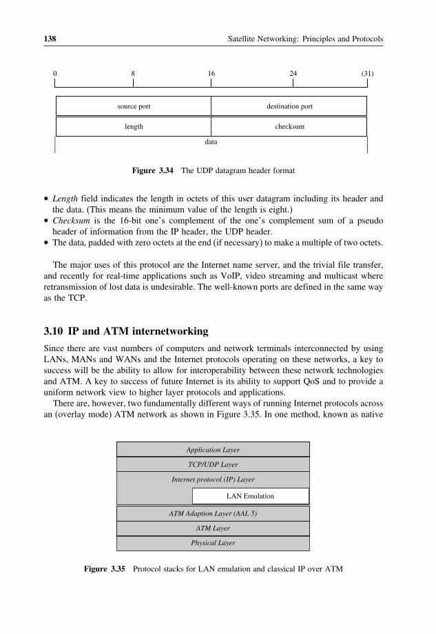
138 Satellite Networking: Principles and Protocols
0 8 16 24 (31)
source port
length
destination port
checksum
data
Figure 3.34 The UDP datagram header format
• Length field indicates the length in octets of this user datagram including its header andthe data. (This means the minimum value of the length is eight.)
• Checksum is the 16-bit one’s complement of the one’s complement sum of a pseudoheader of information from the IP header, the UDP header.
• The data, padded with zero octets at the end (if necessary) to make a multiple of two octets.
The major uses of this protocol are the Internet name server, and the trivial file transfer,and recently for real-time applications such as VoIP, video streaming and multicast whereretransmission of lost data is undesirable. The well-known ports are defined in the same wayas the TCP.
3.10 IP and ATM internetworking
Since there are vast numbers of computers and network terminals interconnected by usingLANs, MANs and WANs and the Internet protocols operating on these networks, a key tosuccess will be the ability to allow for interoperability between these network technologiesand ATM. A key to success of future Internet is its ability to support QoS and to provide auniform network view to higher layer protocols and applications.There are, however, two fundamentally different ways of running Internet protocols across
an (overlay mode) ATM network as shown in Figure 3.35. In one method, known as native
Application Layer
TCP/UDP Layer
Internet protocol (IP) Layer
LAN Emulation
ATM Adaption Layer (AAL 5)
ATM Layer
Physical Layer
Figure 3.35 Protocol stacks for LAN emulation and classical IP over ATM

ATM and Internet Protocols 139
IP over ATM (or classic IP over ATM) mode operation, address resolution mechanisms areused to map Internet addresses directly into ATM addresses, and the Internet packets arethen carried across the ATM network.The alternative method of carrying network layer packets across an ATM network is known
as LAN emulation (LANE). As the name suggests, the function of the LANE protocol is toemulate a local area network on top of an ATM network. Specifically, the LANE protocoldefines mechanisms for emulating either an IEEE 802.3 Ethernet or an 802.5 token ring LAN.
3.10.1 LAN emulation (LANE)
LAN emulation means that the LANE protocol defines a service interface for higher layer(that is, network layer) protocols, which is identical to that of existing LANs, and thatdata sent across the ATM network are encapsulated in the appropriate LAN MAC packetformat. It does not mean that any attempt is made to emulate the actual media access controlprotocol of the specific LAN concerned (that is, CSMA/CD for Ethernet or token passingfor 802.5). In other words, the LANE protocols make an ATM network look and behave likean Ethernet or token ring LAN – albeit one operating much faster than a real such network.The rationale for doing this is that it requires no modifications to higher layer protocols
to enable their operation over an ATM network. Since the LANE service presents the sameservice interface of existing MAC protocols to network layer drivers, no changes are requiredin those drivers. The intention is to accelerate the deployment of ATM, since considerablework remains to be done in fully defining native mode operation for the plethora of existingnetwork layer protocols.It is envisaged that the LANE protocol will be deployed in two types of ATM-attached
equipment:
• ATM network interface cards (NIC): ATM NIC will implement the LANE protocol andinterface to the ATM network, but will present the current LAN service interface to thehigher level protocol drivers within the attached end system. The network layer protocolson the end system will continue to communicate as if they were on a known LAN, usingknown procedures. They will, however, be able to use the vastly greater bandwidth ofATM networks.
• Internetworking and LAN switching equipment: the second class of network gear thatwill implement LANE will be ATM-attached LAN switches and routers. These devices,together with directly attached ATM hosts equipped with ATM NIC, will be used to pro-vide a virtual LAN service, where ports on the LAN switches will be assigned to particularvirtual LANs, independent of physical location. LAN emulation is a particularly good fitto the first generation of LAN switches that effectively act as fast multi-port bridges, sinceLANE is essentially a protocol for bridging across ATM. Internetworking equipment, suchas routers, will also implement LANE to allow for virtual LAN internetworking.
The LANE protocols operate transparently over and through ATM switches, using onlystandard ATM signalling procedures. ATM switches may well be used as convenient plat-forms upon which to implement some of the LANE server components, but this is indepen-dent of the cell relay operation of the ATM switches themselves. This logical decoupling isone of the great advantages of the overlay model, since it allows ATM switch designs to pro-ceed independently of the operation of overlying internetworking protocols, and vice versa.

140 Satellite Networking: Principles and Protocols
The basic function of the LANE protocol is to resolve MAC addresses into ATM addresses.By doing so, it actually implements a protocol of MAC bridge functions using ATM; hencethe close fit with current LAN switches. The goal of LANE is to perform such addressmappings so that LANE end systems can set up direct connections between themselves andforward data. The element that adds significant complexity to LANE, however, is supportingLAN switches – that is, LAN bridges. The function of a LAN bridge is to shield LANsegments from each other.
3.10.2 LANE components
The LANE protocol defines the operation of a single emulated LAN (ELAN). MultipleELANs may coexist simultaneously on a single ATM network. A single ELAN emulateseither Ethernet or token ring, and consists of the following entities:
• LAN emulation client (LEC): a LEC is the entity in an end system that performs dataforwarding, address resolution and other control functions for a single end-system withina single ELAN. A LEC also provides a standard LAN service interface to any higherlayer entity that interfaces to the LEC. In the case of an ATM NIC, for instance, the LECmay be associated with only a single MAC address, while in the case of a LAN switch;the LEC would be associated with all MAC addresses reachable through the ports of thatLAN switch assigned to the particular ELAN.
• LAN emulation server (LES): the LES implements the control function for a particularELAN. There is only one logical LES per ELAN, and to belong to a particular ELANmeans to have a control relationship with that ELAN’s particular LES. Each LES isidentified by a unique ATM address.
• Broadcast and unknown server (BUS): the BUS is a multicast server that is used to floodunknown destination address traffic and forward multicast and broadcast traffic to clientswithin a particular ELAN. The BUS to which a LEC connects is identified by a uniqueATM address. In the LES, this is associated with the broadcast MAC address, and thismapping is normally configured into the LES.
• LAN emulation configuration server (LECS): the LECS is an entity that assigns individualLANE clients to particular ELANs by directing them to the LES that correspond to theELAN. There is logically one LECS per administrative domain, and this serves all ELANswithin that domain.
3.10.3 LANE entity communications
LANE entities communicate with each other using a series of ATM connections. LECs main-tain separate connections for data transmission and control traffic. The control connectionsare as follows:
• Configuration direct VCC: this is a bi-directional point-to-point VCC set up by the LECto the LECS.
• Control direct VCC: this is a bi-directional VCC set up by the LEC to the LES.

ATM and Internet Protocols 141
• Control distribute VCC: this is a unidirectional VCC set up from the LES back to theLEC; this is typically a point-to-multipoint connection.
The data connections are as follows:
• Data direct VCC: this is a bi-directional point-to-point VCC set up between two LECsthat want to exchange data. Two LECs will typically use the same data direct VCC tocarry all packets between them, rather than opening a new VCC for each MAC addresspair between them, so as to conserve connection resources and connection set-up latency.Since LANE emulates existing LAN, including their lack of QoS support, data directconnections will typically be UBR or ABR connections, and will not offer any type ofQoS guarantees.
• Multicast send VCC: this is a bi-directional point-to-point VCC set up by the LEC to theBUS.
• Multicast forward VCC: this is a unidirectional VCC set up to the LEC from the BUS,this is typically a point-to-multipoint connection, with each LEC as a leaf.
The higher layer protocol processing within the router is unaffected by the fact that therouter is dealing with emulated or physical LAN. This is another example of the value ofLANE in hiding the complexities of the ATM network.One obvious limitation of this approach, however, is that the ATM router may eventually
become a bottleneck, since all inter-ELAN traffic must traverse the router. LANE has anotherlimitation. By definition, the function of LANE is to hide the properties of ATM from higherlayer protocols. This is good, particularly in the short to medium term, since it precludesthe need for any changes to these protocols. On the other hand, LANE also precludes theseprotocols from ever using the unique benefits of ATM, and specifically, its QoS guarantees.LANE is defined to use only UBR and ABR connections, since it is these that map best tothe connectionless nature of MAC protocols in LANs.
3.10.4 Classical IP over ATM
The IETF IP-over-ATM working group has developed protocols for IP transport over ATM.The transport of any network layer protocol over an overlay mode ATM network involvestwo aspects: packet encapsulation and address resolution. Both of these aspects have beentackled by the IETF, and are described below:
3.10.5 Packet encapsulation
The IETF has defined a method for transporting multiple types of network or link layerpackets across an ATM (AAL 5) connection and also for multiplexing multiple packet typeson the same connection. As with LANE, there is value to reusing the same connection forall data transfers between two nodes since this conserves the connection resource space, andsaves on connection set-up latency, after the first connection set up. This is only possible,however, as long as only UBR or ABR connections are used – if the network layer requiresQoS guarantees then every distinct flow will typically require its own connection.

142 Satellite Networking: Principles and Protocols
In order to allow connection re-use, there must be a means for a node that receives anetwork layer packet across an ATM connection to know what kind of packet has beenreceived, and to what application or higher level entity to pass the packet to; hence, thepacket must be prefixed with a multiplexing field. Two methods for doing this are definedin RFC 1483:
• Logical link control/sub-network access point (LLC/SNAP) encapsulation. In this method,multiple protocol types can be carried across a single connection with the type of encap-sulated packet identified by a standard LLC/SNAP header. A further implication ofLLC/SNAP encapsulation, however, is that all connections using such encapsulations ter-minate at the LLC layer within the end systems, as it is here that the packet multiplexingoccurs.
• VC multiplexing. In the VC multiplexing method, only a single protocol is carried acrossan ATM connection, with the type of protocol implicitly identified at connection set up.As a result, no multiplexing or packet type field is required or carried within the packet,though the encapsulated packet may be prefixed with a pad field. The type of encapsulationused by LANE for data packets is actually a form of VC multiplexing.
The VC multiplexing encapsulation may be used where direct application-to-applicationATM connectivity, bypassing lower level protocols, is desired. As discussed earlier, however,such direct connectivity precludes the possibility of internetworking with nodes outside theATM network.The LLC/SNAP encapsulation is the most common encapsulation used in the IP over ATM
protocols. The ITU-T has also adopted this as the default encapsulation for multiprotocoltransport over ATM, as has the ATM Forum’s multiprotocol over ATM group. In relatedwork, the IP over ATM group has also defined a standard for a maximum transfer unit(MTU) size over ATM. This defines the default MTU as 9180 bytes to be aligned with theMTU size for IP over SMDS. It does, however, allow for negotiation of the MTU beyondthis size, to the AAL 5 maximum of 64 kbytes, since important performance improvementscan be gained by using larger packet sizes. This standard also mandates the use of IP pathMTU discovery by all nodes implementing IP over ATM to preclude the inefficiency of IPfragmentation.
3.10.6 IP and ATM address resolution
In order to operate IP over ATM, a mechanism must be used to resolve IP addresses to theircorresponding ATM addresses. For instance, consider the case of two routers connectedacross an ATM network. If one router receives a packet across a LAN interface, it will firstcheck its next-hop table to determine through which port, and to what next-hop router, itshould forward the packet. If this look-up indicates that the packet is to be sent across anATM interface, the router will then need to consult an address resolution table to determinethe ATM address of the destination next-hop router (the table could also be configured, ofcourse, with the VPI/VCI value of a PVC connecting the two routers).This address resolution table could be configured manually, but this is not a very scalable
solution. The IP-over-ATM working group has defined a protocol to support automaticaddress resolution of IP addresses in RFC 1577. This protocol is known as ‘classical IP over

ATM and Internet Protocols 143
ATM’ and introduces the notion of a logical IP sub-net (LIS). Like a normal IP sub-net, anLIS consists of a group of IP nodes (such as hosts or routers) that connect to a single ATMnetwork and belong to the same IP sub-net.To resolve the addresses of nodes within the LIS, each LIS supports a single ATM address
resolution protocol (ATMARP) server, while all nodes (LIS clients) within the LIS areconfigured with the unique ATM address of the ATMARP server. When a node comes upwithin the LIS, it first establishes a connection to the ATMARP server, using the configuredaddress. Once the ATMARP server detects a connection from a new LIS client, it transmitsan inverse ARP 53 request to the attaching client and requests the node’s IP and ATMaddresses, which it stores in its ATMARP table.Subsequently, any node within the LIS wishing to resolve a destination IP address would
send an ATMARP request to the server, which would then respond with a ATMARP reply ifan address mapping is found. If not, it returns an ATM_NAK response to indicate the lack ofa registered address mapping. The ATMARP server ages out its address table for robustness,unless clients periodically refresh their entry with responses to the servers inverse ARPqueries. Once an LIS client has obtained the ATM address that corresponds to a particularIP address, it can then set up a connection to the address.The operation of the classical model is very simple. It does, however, suffer from a
number of limitations. One of these limitations is indicated by the phrase ‘classical’. Whatthis means is that the protocol does not attempt to change the IP host requirement thatany packet for a destination outside the source node’s IP sub-net must be sent to a defaultrouter. This requirement, however, is not a good fit to the operation of IP over ATM, anda whole class of other ‘non-broadcast multi-access’ (NBMA) networks, such as frame relayor X.25. In all such networks, it is possible to define multiple LIS, and the network itselfcould support direct communications between two hosts on two different LIS.However, since RFC 1577 preserves the host requirements, in the context of IP over
ATM, communications between two nodes on two different LIS on the same ATM networkmust traverse each ATM router on the intermediate hops on the path between the source anddestination nodes. This is clearly inefficient, since the ATM routers become bottlenecks;this also precludes the establishment of a single connection with a requested QoS betweenthe two nodes.
Further reading[1] Black, U., ATM: Foundation for Broadband Networks, Prentice Hall Series in Advanced Communication
Technologies, 1995.[2] Comer, D.E., Computer Networks and Internet, 3rd edition, Prentice Hall, 1999.[3] Cuthbert, G., ATM: broadband telecommunications solution, IEE Telecommunication Series No.29, 1993.[4] Tanenbaum A., Computer Networks, 4th edition. Prentice Hall, 2003.[5] RFC 791, Internet Protocol, Jon Postel, IETF, September 1981.[6] RFC 793, Transmission control protocol, Jon Postel, IETF, September 1981.[7] RFC 768, User datagram protocol, Jon Postel, IETF, August 1980[8] RFC 826, An Ethernet Address Resolution Protocol, David C. Plummer, IETF, November 1982.[9] RFC 903, A Reverse Address Resolution Protocol, Finlayson, Mann, Mogul, Theimer, IETF, June 1984.
[10] RFC 2328, OSPF Version 2, J. Moy, IETF, April 1998.[11] RFC 2453, RIP Version 2, G. Malkin, IETF, November 1998.[12] RFC 1771, A Border Gateway Protocol 4 (BGP-4), Y. Rekhter and T. Li, IETF, March 1995.[13] RFC 2581, TCP Congestion Control, M. Allman, V. Paxson and W. Stevens, IETF, April 1999.

144 Satellite Networking: Principles and Protocols
[14] RFC 1483, Multiprotocol Encapsulation over ATM Adaptation Layer 5, Juha Heinanen, IETF, July 1993.[15] RFC 1577, Classical IP and ARP over ATM, M. Laubach, IETF, January 1994.
Exercises
1. Explain the concepts of the ATM protocol and technology.2. Discuss the functions of ATM adaptation layers (AAL) and the type of services
they provide.3. Use a sketch to explain how to transport ATM cells using an E1 connection.4. Explain the concepts of VP and VC switches.5. Explain how to achieve QoS and efficient utilisation of network resources.6. Describe the leaky bucket and virtual scheduling algorithms.7. Explain the functions of the Internet protocol (IP).8. Explain the transmission control protocol (TCP) and user datagram protocol (UDP)
and their differences.9. Explain the deployment scenarios of LAN emulation.10. Explain the concept of classical IP over ATM.

4Satellite Internetworking withTerrestrial Networks
This chapter aims to provide an introduction to satellite internetworking with terrestrialnetworks and related access and transit transmission networks. When you have completedthis chapter, you should be able to:
• Know the basic terminologies and concepts concerning internetworking.• Know about network traffic related to user plane, control plane and management plane.• Describe the network hypothetical reference connection.• Describe the differences between multiplexing and multiple access schemes.• Understand the basic concept of traffic engineering in telephony networks.• Understand the evolution of digital networks including PDH, SDH and ISDN.• Identify different types of signalling schemes.• Identify the performance objectives of satellite networks in end-to-end reference connec-tions.
• Understand the issues of SDH over satellite.• Understand the issues of ISDN over satellite.
4.1 Networking concepts
Telecommunication networks were originally designed, developed and optimised withrespect to the speech transmission quality of narrow-band 3.1 kHz real-time telephony ser-vices.In the early generation of data networks in wide area, people tried to fully utilise the
3.1 kHz for data communications without the additional costs of a network infrastructure.
Satellite Networking: Principles and Protocols Zhili Sun© 2005 John Wiley & Sons, Ltd

146 Satellite Networking: Principles and Protocols
At that time, the transmission speed of the data terminals was relatively low. In addition totelephony services, the networks can also support the transmission of non-voice signals suchas fax and modem transmission, and wholly digital data transmission. To some extent, thetelecommunication networks could meet the transmission demand of data communications.Because of the development of computers as network terminals, high-speed data networks
had to be developed to meet the demand of data communications. This led to the developmentof different types of networks for different services. Traffic on data networks is becominglarger and larger, and the same applies to network capacity. The increase in traffic generatedthe opportunity to transport telephony voice services over data networks. High-capacity userterminals and network technologies enable the convergence of telephony services and dataservices, and also broadcasting services. A new type of network, broadband networks, hasbeen developed to support the convergence of services and networks.All these developments are great for new services and applications, but also bring great
challenges to internetwork between these different types of networks. Due to economicreasons, new networks are ‘forced’ to interface with legacy networks.It is even more of a challenge for satellite networks to interwork with all these different
types of networks. One of the great problems in telephony networks is that the terminalsand networks are so well engineered that any change in one party would be restricted inthe other party. Modern networks try to separate the functions of user terminals from thenetworks so that the user terminals provide services without concerning too much abouthow the traffic is transported over the networks, and the networks provide different typesof transport schemes with little concern about how the terminals are going to process thetraffic.We will follow the same principle to discuss satellite internetworking with terrestrial
networks, i.e., what the requirements are from the terrestrial networks, and how the satellitenetworks will be able to meet these requirement for internetworking purposes.Medium and large private networks consist of several interconnected multi-line telephony
systems (MLTS). The terms ‘corporate network’ or ‘enterprise network’ are sometimes usedto describe a large private network; in some countries these terms are used in a legal sense fora group of interconnected private networks. From the point of view of networking, there isno difference between a large private network and several smaller interconnected networks.Therefore, only the term ‘private network’ will be used to refer to this type of networks.A private network can be a terminating network (one to which terminal equipment is
connected). It can also provide transit connections between other networks. We will empha-sise the case for terminating networks, as the transit network case is quite similar to publicnetworks.We will focus more on the principles of all kinds of intra- or internetwork connections
rather than detailed implementations, regardless of the number of public or private networksinvolved, or the specific configuration in which they are interconnected.Therefore, there is neither restriction on the network with respect to size, configuration,
hierarchy, technology used, nor on the components of the network.Although all communications networks are now digital (almost universal in Europe), radio
resource management in the frequency domain still uses the same principle as analoguenetworks. Naturally we will focus our discussion more on digital networks because of theprevalence of digital signal transmission media and digital signal handling in switchingequipment.

Satellite Internetworking with Terrestrial Networks 147
4.2 Networking terminology
Before going into details, we will explain the definitions of a number of terms pertinent tothe relevant concepts:
• Reference point: is a conceptual group at a conjunction of two non-overlapping functiongroups. The two function groups exchange information through the reference point usingthe same defined conceptual group.
• Interworking: is a general term describing two systems or subsystems exchanging infor-mation, and covers both internetworking and service interworking aspects.
• Internetworking: describes the concept of the interconnection of different networks toprovide services interoperable across these networks.
• Service interworking: describes the concept that the full or limited service of one networkis converted or made available in another (similar) service of the same network or anothernetwork.
• Interworking unit (IWU): is a physical entity located between reference points containingone or more interworking functions (IWF). It is used to interconnect two function groups.If they do not have common reference points, mapping or translating is required for thetwo function groups to communicate with each other.
4.2.1 Private network
The term ‘private network’ is used to describe a network which provides features only to arestricted user group in contrast to the public network (PSTN) available to the general public.In general, a private network is a terminating network and consists of several interconnectednodes (i.e. PBXs, routers, gateways), with interconnections to other networks via mainlypublic networks.A private network has the following characteristics:
• It consists normally of more than one network node element, connected via public networksor leased lines or via a virtual private network (VPN).
• It provides network functions and all other features only to a single user or to a group ofusers, and is not accessible to the general public.
• It is not limited by geographical size or to a specific national area or region, though mostof the private networks use LAN technologies in a single site.
• It has no limitation with regard to the number of extensions and access points to othernetworks.
4.2.2 Public network
The term ‘public network’ refers to networks providing transmission, switching and routingfunctions as well as features which are available to the general public, and are not restrictedto a specific user group. In this context, the word ‘public’ does not imply any relation to thelegal status of the network operator.In some cases, a public network may provide a limited set of features only. In a competitive
environment, a public network may be restricted to serve a limited number of customers, or

148 Satellite Networking: Principles and Protocols
restricted to specific features or functions. Generally, public networks provide access pointsto other networks or terminals only within a specific geographical area.From the point of view of an end-to-end connection, a public network can function either
as a ‘transit network’ (a link between two other networks) or as a combination of ‘transit andterminating network’ in cases where the public network provides connections to terminalequipment such as telephone sets, PBXs, routers or gateways.
4.2.3 Quality aspects of telephony services
In telephony networks, quality aspects take into consideration both the telephone set anddifferent components in the network. The perception of speech transmission quality duringa telephone conversation is primarily a ‘subjective’ judgement. The concept of ‘quality’may not be considered as a unique discrete quantity, but may vary, depending on the user’sexpectation of sufficient ‘speech transmission quality’ for a 3.1 kHz telephony call for theterminal mode (e.g. handset) as well as the particular service (e.g. wireless). An end-to-endconsideration is taken into account from one human’s mouth to another human’s ear.For the judgement of the quality in a given configuration, and the performance of ‘subjec-
tive tests’, the ITU-T has developed several methods. One of the most common methods is toperform laboratory tests (e.g. ‘listening-only tests’), wherein the test subjects are requestedto classify the perceived quality into categories. For example, a ‘quality rating’ can be gradedon a 1–5 grade scale as bad, poor, fair, good and excellent.The scores are used to calculate the average value of the judgement of several test
subjects for the same test configuration. The result is the so-called ‘mean opinion score’(MOS), which may, theoretically, range between 1 and 5. An assessment about the speechtransmission quality can also be obtained by calculating the percentage of all test personsrating the configuration as ‘good or better’ or as ‘poor or worse’. For a given connectionthese results are expressed as ‘percentage good or better’ (%GoB) and ‘percentage poor orworse’ (%PoW).Therefore, it is a complicated task to evaluate quality of services in telephony networks,
and involves the collection of the necessary information on the various network componentsin the configuration investigated and their contribution of transmission impairments thatimpact the end-to-end connection speech transmission quality. The ITU-T has developedseveral methods and tools to evaluate QoS over telephony networks.In digital networks, the impairment in any part of the network does not propagate from
one part to the other part. Therefore, the quality of services can be evaluated for each elementseparately. For example, the modern network terminals are capable of buffering digitisedvoice or putting the voice into memory before playing out. The terminals should be giventhe freedom of how long to keep and how much to buffer the voice. Similarly, modernnetworks process the digitised voice in terms of frames or packets, and should also be giventhe freedom of how much time to process and what the sizes of frames or packet should be.
4.2.4 IP based network
IP based networks have been developed based on the Internet protocols transmitted overdifferent types of network technologies including LAN, WAN and wireless and satellite

Satellite Internetworking with Terrestrial Networks 149
networks. From a board gateway protocol (BGP) router point of view, the world consistsof autonomous systems (AS) and lines connecting them. Two AS are considered connectedif there is a line between boarder routers in each one. The network can be grouped intothree categories: the first category is the stub networks, which have only one BGP routerconnecting to the outside, hence cannot be used for transit traffic. The second category is themulti-connection networks, which can be used for transit traffic except that they refuse tocarry the transit traffic. Finally the third category is the transit networks, which are willingto handle third parties, possibly with some restrictions, and usually charge for their services.Each AS has a similar structure. The stub network sending traffic to and receiving trafficfrom backbone networks, and backbone networks to transport the traffic between the AS.Typical networks include:
• private enterprise intranets (LANs);• Internet service provider (ISP) domains via WANs;• public Internet (concatenated WANs).
They consist of internal routers and edge routers (e.g. between LAN and WAN). Thetelephony network can be used to link the routers together and link IP terminals to ISPs.IP based networks rely on the Internet protocol (IP) and provide packet-based transport
of data. Thus, a digitised speech signal will be divided into small segments for the real-timetransport protocol (RTP) in the application layer, the user datagram protocol (UDP) at thetransport layer protocol and then the Internet protocol (IP) at the network layer. The headerof these protocol layers in general contains the following data:
• specific information for dealing with real-time applications;• port numbers to identify the process of real-time applications;• IP addresses for packet delivery;• network physical addresses and frames to transport the IP packets.
Finally, at the receiving side, the speech segments are used to construct the original con-tinuous digital speech signal. For non-real-time data services, transmission control protocol(TCP) is used at the transport layer.
4.3 Network elements and connections
Network components in an end-to-end connection can be categorised into three main groups:network terminals, network connections and network nodes.
4.3.1 Network terminals
With respect to speech transmission, terminals are all types of telephone sets, digital oranalogue, wired, cordless or mobile, including the acoustical interfaces to the user’s mouthand ear. These components are characterised by their send loudness rating (SLR) and receiveloudness rating (RLR), which contribute to the overall loudness rating (OLR) of a connection.Other parameters, such as the side tone masking rating (STMR), the listener side tone rating

150 Satellite Networking: Principles and Protocols
(LSTR), the design of the handset (D-factor), and the frequency response in send and receivedirections and the noise floor, also contribute to the end-to-end connection rating of speechtransmission quality.In the case of wireless or IP based systems, additional distortions and delay may be added,
depending on the coding and modulation algorithms used in such interfaces. However, withpacket networks, there are great advantages in the terminal with memory and processingpower overcoming the problems of telephony networks.
4.3.2 Network nodes
Network nodes are all types of switching equipment, such as local PBXs and switches intelephony networks and routers in Internet. These nodes may use analogue or digital switch-ing or packet-based technology. The main impairment contributions of analogue systems areloss and noise in telecommunication networks. Where four-wire to two-wire conversionstake place within or between switching equipment interfaces, signal reflections contributeto impairments as a source for echo effects. Digital switching systems contribute to theend-to-end delay, due to signal processing, and also to the amount of quantisation distor-tion associated with digital pads and code conversion. Packet-based routers contribute, inaddition, to delay variation versus time and packet loss.
4.3.3 Network connections
Network connections use all kinds of media as the facility between network nodes andbetween nodes and network terminals. The physical media of these connections may bemetallic (copper), fibre optics or radio. The signal form is either analogue or digital. Impair-ments associated with analogue signal transmission include propagation time (generallyproportional to distance), loss, frequency response and noise (mainly due to longitudinalinterference). Impairments due to frequency response and noise can usually be neglected forshort and medium line lengths.For digital transmission, the main impairment is caused by the propagation time via metal-
lic, optic and radio media. For wireless sections, additional delay is introduced, dependingon the coding and modulation algorithm used. Where the connection includes analogue-to-digital conversion, loss and distortion are additional impairment factors.Multiplexing is generally used to transport several channels via one single physical media.
A variety of multiplexing systems are in use in the existing networks:
• time division multiplex (TDM);• digital circuit multiplication equipment (DCME);• packet-based networks, connection oriented (ATM) and connectionless (Ethernet, LAN,IP, etc.).
In telephony networks, connections support either 64 kbit/s pulse code modulation (PCM),or the more recently introduced compression techniques based on low bit-rate codecs. Inbroadband networks, the connections will be able to support traffic at a much higher speedof video and data in addition to the telephony voice services.
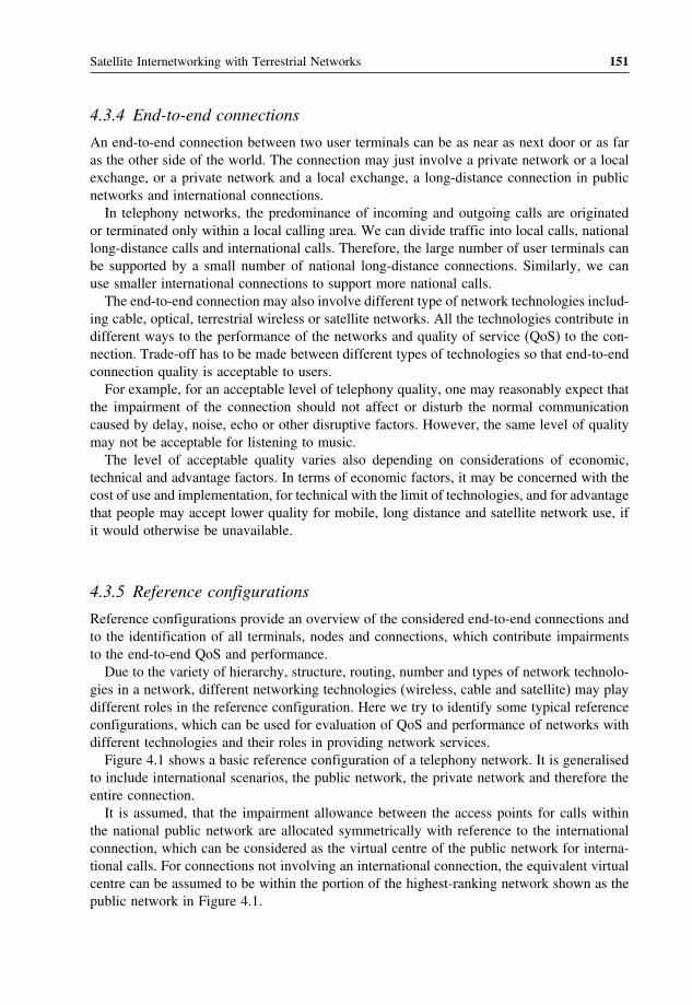
Satellite Internetworking with Terrestrial Networks 151
4.3.4 End-to-end connections
An end-to-end connection between two user terminals can be as near as next door or as faras the other side of the world. The connection may just involve a private network or a localexchange, or a private network and a local exchange, a long-distance connection in publicnetworks and international connections.In telephony networks, the predominance of incoming and outgoing calls are originated
or terminated only within a local calling area. We can divide traffic into local calls, nationallong-distance calls and international calls. Therefore, the large number of user terminals canbe supported by a small number of national long-distance connections. Similarly, we canuse smaller international connections to support more national calls.The end-to-end connection may also involve different type of network technologies includ-
ing cable, optical, terrestrial wireless or satellite networks. All the technologies contribute indifferent ways to the performance of the networks and quality of service (QoS) to the con-nection. Trade-off has to be made between different types of technologies so that end-to-endconnection quality is acceptable to users.For example, for an acceptable level of telephony quality, one may reasonably expect that
the impairment of the connection should not affect or disturb the normal communicationcaused by delay, noise, echo or other disruptive factors. However, the same level of qualitymay not be acceptable for listening to music.The level of acceptable quality varies also depending on considerations of economic,
technical and advantage factors. In terms of economic factors, it may be concerned with thecost of use and implementation, for technical with the limit of technologies, and for advantagethat people may accept lower quality for mobile, long distance and satellite network use, ifit would otherwise be unavailable.
4.3.5 Reference configurations
Reference configurations provide an overview of the considered end-to-end connections andto the identification of all terminals, nodes and connections, which contribute impairmentsto the end-to-end QoS and performance.Due to the variety of hierarchy, structure, routing, number and types of network technolo-
gies in a network, different networking technologies (wireless, cable and satellite) may playdifferent roles in the reference configuration. Here we try to identify some typical referenceconfigurations, which can be used for evaluation of QoS and performance of networks withdifferent technologies and their roles in providing network services.Figure 4.1 shows a basic reference configuration of a telephony network. It is generalised
to include international scenarios, the public network, the private network and therefore theentire connection.It is assumed, that the impairment allowance between the access points for calls within
the national public network are allocated symmetrically with reference to the internationalconnection, which can be considered as the virtual centre of the public network for interna-tional calls. For connections not involving an international connection, the equivalent virtualcentre can be assumed to be within the portion of the highest-ranking network shown as thepublic network in Figure 4.1.

152 Satellite Networking: Principles and Protocols
Private network
User terminal
Public network
Internationalconnection
Access network Transit network
Figure 4.1 Basic configuration of access and transit networks
The private network normally connects to a local exchange (e.g. LEC), usually the lowesthierarchy and the common connection point in a public network. It is also possible to connectthe private network directly to a higher hierarchy level, e.g. an international connection,bypassing the local exchange. In some cases, especially for larger private networks, bypassmay permit more allocation of specific transmission parameters, e.g. delay, to the privatenetwork.A virtual private network (VPN) although provided by the public network operator,
should be considered as part of the private network. The same is valid for leased linesinterconnecting private networks usually provided by public network carriers. The privatenetwork with leased lines and VPN connections has some implications on end-to-end QoSand performance.
4.4 Network traffic and signalling
Internetworking involves the following types of traffic: user traffic, signalling traffic andmanagement traffic. User traffic is generated and consumed directly at user terminals.Signalling traffic conveys the intelligence for subscribers to interconnect with the othersacross the networks. Management traffic provides information in the networks for effectivecontrol of the user traffic and network resources dynamically to meet the QoS requirementof the user traffic. User traffic belongs to application layer, which consumes the majoramount of network resources (such as bandwidth). The management traffic also consumesa significant amount of resources. Figure 4.2 illustrates the relationships between user,signalling and management functions.
4.4.1 User traffic and network services
User traffic is generated by a range of user services. Satellite networks can support a widerange of telecommunication services including telephony, fax, data, ISDN, B-ISDN, etc.Figure 4.3 illustrates some typical network connection and interfaces.Telephony, fax and various low bit-rate data transmission services were originally based
on analogue transmission. Nowadays, they are systematically implemented and developedbased on digital technologies. In analogue transmission, network bandwidth is allocated inthe frequency domain for the duration of network connection. In the digital domain, networkbandwidth is allocated in the time domain. The use of time division multiplexed digitalcarriers, especially when combined with technologies such as adaptive differential pulse

Satellite Internetworking with Terrestrial Networks 153
Switching Block
Call Control
Switch
Network management
Management traffic
Signalling traffic
User traffic
Management Network
Signalling & Controlling
network
User traffic transport network
Operation Systems Functions (OSF)
Mediation function (MF)
Figure 4.2 Relationships between user, signalling and management functions
Local cross
connectionCustomer’s terminal
X series Interface
V series Interface
Modem
64 kbit/s local line
Analogue local line
Notes: Satellites can inprinciple be used on anysection (or combination ofsections) of this.
Main cross
connection
International cross
connection
Customer’s terminal
T1 or E1 interface
Figure 4.3 Example of network connections and interfaces
code modulation (ADPCM), low bit-rate encoding and digital speech interpolation (DSI)with digital circuit multiplication equipment (DCME), can provide increased traffic capacityin terms of a large numbers of channels on such carriers.For ISDN service, the basic user access includes two B-channels at 64 kbit/s and a
D-channel at 16 kbit/s. It can support digital voice, 64 kbit/s data in circuit and packetswitched modes, telex, fax and slow-scan video. The primary access is 2.048Mbit/s inEurope or 1.544Mbit/s in North America and Japan. It can support fast fax, videoconference,high-speed data transmission, and high-quality audio or sound programme channels andpacket-switched data services. It can also support multiplexed data streams of below 64 kbit/s.For a broadband ISDN service, the user can access at speeds as high as 155.520Mbit/sor more. It can support integration of voice, video and data or combinations of these asmultimedia services.Satellite usage must take into account the end-to-end customer requirements as well as
signalling/routing constraints of a particular network configuration. The requirements ofthese services may also differ depending on whether they are carried on a dedicated (leased)circuit within the main network or a switched connection.

154 Satellite Networking: Principles and Protocols
4.4.2 Signalling systems and signalling traffic
Traditionally, telephony networks classified signalling generally into subscriber signallingand inter-switch signalling and functionally into audible-visual signalling, supervisory sig-nalling and address signalling.Subscriber signalling tells the local switch that a subscriber wishes to contact another
subscriber by dialling the number identifying the distance subscriber. Inter-switch signallingprovides information allowing switches to route the call properly. It also provides supervisionof the call along its path. Signalling provides information for the network operator to chargefor the use of network services.The audible-visual signalling provides alerting (such as ring, paging and off-hook warning)
and progress of the call (such as dial tone, busy tone and ring back). Supervisory signallingprovides forward control from user terminal to local switch to seize, hold or release aconnection and backward status including idle, busy and disconnect. Address signalling isgenerated from the user terminal by rotary dialling or digital dialling and used by the networkto route the call.Two trade-off factors are the signalling delay after the user dialled the number and
signalling cost for setting up the call, as the network needs to reserve resources link by linkuntil the call is set up successfully or has failed.
4.4.3 In-band signalling
In telephony networks, in-band signalling refers to signalling systems using an audio tone,or tones inside the conventional voice channel, to convey signalling information. It is brokendown into three signalling categories: single frequency (SF), two frequency (TF), and multi-frequency (MF). As conventional voice channel occupies the frequency band from 300Hzto 3400Hz, SF and TF signalling systems utilise the 2000–3000 band where less speechenergy is concentrated.SF signalling is used almost exclusively for supervision. The most commonly used fre-
quency is 2600Hz, particularly in North America. On two-wire trucks 2600Hz is usedin one direction and 2400Hz in the other. Figure 4.4(a) illustrates the concept of in-band
Sign
al le
vel (
dBm
)
Speech band
4000
Frequency (Hz)
2600 Hz
Sign
al le
vel (
dBm
)
Speech band
Frequency(Hz)
3825 Hz (ITU) 3700 Hz (USA)
(a) In-band signalling (b) Out-of-band signalling
0 1000 2000 3000 40000 1000 2000 3000
Figure 4.4 Analogue network in-band signalling and out-of-band signalling

Satellite Internetworking with Terrestrial Networks 155
Channel 1
1 2 3 4 5 6 7
Channel 2
1 2 3 4 5 6 7
Channel N
1 2 3 4 5 6 7….
Signalling bit in the channels
Channel 1
1 2 3 4 5 6 7 8
Channel 2
1 2 3 4 5 6 7 8
One of the channels is used for signalling
….
(a) In-band signalling.
(b) Out-of-band signalling.
88 8
1 2 3 4 5 6 7 8
Figure 4.5 Digital network in-band signalling and out-of-band signalling
signalling of 2600Hz within the frequency band, and Figure 4.4(b) illustrates two out-of-band signalling of 3700Hz used in North America or 3825Hz for ITU. Similarly indigital networks, there can also be in-band signalling and out-of-band-signalling as shownin Figure 4.5.A two-frequency signal is used for both supervision (line signalling) and address sig-
nalling. SF and TF signalling systems are often associated with carrier (FDM) operation.In supervision line signalling ‘idle’ refers to the on-hook condition while ‘busy’ refers tothe off hook condition. Thus, for such types of line signalling there are two audio tones, ofwhich SF and TF are typical, for ‘tone on when idle’ and ‘tone on when busy’.You may have noticed that a major problem with in-band signal is the possibility of ‘talk-
down’ which refers to the premature activation or deactivation of supervisory equipment byan inadvertent sequence of voice tones through the normal use of the channel. Such tonescould simulate the SF tone, forcing a channel dropout (i.e., the supervisory equipment wouldreturn the channel to idle state). Chances of simulating TF tone set are less likely. To avoidthe possibility of talk-down on an SF circuit, a time delay circuit or slot filters may be usedto bypass the signalling tone. Such filters can cause some degradation to speech unless theyare switched off during conversation. They must be switched off if the circuit is used fordata transmission. Therefore, TF or MF signalling systems overcome the problem of SF. TFsignalling is widely used for addressing signalling.Multi-frequency (MF) signalling is widely used for addressing signalling between
switches. It is an in-band method utilising five or six tone frequencies, two at a time, ofwhich each have four different frequencies, forming the typical signalling of 16 buttons inthe telephone set.
4.4.4 Out-of-band signalling
With out-of-band signalling, supervisory information is transmitted above 3400Hz of theconventional voice band. In all cases, it is a single frequency system. The advantage ofout-of-band signalling is that either system ‘tone on’ or ‘tone off’ may be used when idle.Talk-down cannot occur because all supervisory information is passed out of band awayfrom the speech information portion of the channel. The preferred out-of-band frequencyis 3825Hz, whereas 3700Hz is commonly used in the US (see Figure 4.4(b)). Out-of-band

156 Satellite Networking: Principles and Protocols
signalling is attractive, but one drawback is that when channel patching is required, signallingleads have to be patched as well.
4.4.5 Associated and disassociated channel signalling
Traditionally, signalling goes along with the traffic on the same channel it is associated withon the same media. This signalling may or may not go on the same media or path. Mostoften, this type of signalling is transported on a separate channel in order to control a groupof channels. A typical example is the European PCM E1 where one separate digital channelsupports all supervisory signalling for 30 traffic channels. It is still associated channelsignalling if it travels on the same media and path as its associated traffic channels.If the separated signalling channel follows a different path using perhaps different media,
it is called disassociated signalling. See Figure 4.6. ITU-T Signalling System No. 7 (ITU-TSS7) always uses separated channels, but can be associated and disassociated. Disassociatedchannel signalling is also called non-associated channel signalling.
4.4.6 ITU-T signalling system No. 7 (ITU-T SS7)
ITU-T SS7 was developed to meet the advanced signalling requirements of the all-digitalnetwork based on the 64 kbit/s channels. It operates in a quite different manner than
Switch Network
Exchange A
SF
SF
SF
SF sender
Signal
Processor
Exchange BSignal
Switch Network
SF
SF
SF
SF receiver
Processor
Trunks
(a) Conventional associated channel signalling.
Switch Network
Exchange A Exchange B
Switch Network
Processor
Trunks
(b) Separate channel signalling with common channel signalling (CCS).
ProcessorCCS
TerminalCCS
TerminalSignalling
Figure 4.6 Associated and separate signalling

Satellite Internetworking with Terrestrial Networks 157
conventional signalling systems. Nevertheless, it must provide supervision of circuits, addresssignalling, call progressing and alert notification. It is a data network entirely dedicated tointerswitching signalling, and can be summarised as the following:
• it is optimised for operation with digital networks where switches use stored-programcontrol (SPC);
• it meets the requirements of information transfer for inter-processor transactions withdigital communication networks for call control, remote control, network database accessand management, and maintenance signalling; and
• it provides a reliable means of information transfer in the correct sequence without lossor duplication.
Since 1980, it has become known as the signalling system for ISDN. The SS No.7 networkmodel consists of network nodes, termed signalling points (SP), which are interconnectedby point-to-point signalling links, with all the links between two SPs called a link set.Messages between two SPs may be routed over a link set directly connecting the two points.This is referred to as the associated mode of signalling. Messages may also be routed viaone or more intermediate points relaying the messages at the network layer. This is calledthe non-associated mode of signalling. It supports a special case of static routing, calledquasi-associated mode, in which routing only changes in response to events such as linkfailures or addition of new SPs. The function of relaying messages at the network layer iscalled the signalling transfer points (STP).There are certain relationships between the SS No.7 and the OSI/ISO reference model as
illustrated as Figure 4.7.It can be seen that SS No.7 has three layers corresponding to layers 1–3 of the OSI/ISO
reference model within the communication networks. The application processes within acommunication network invoke protocol functionality to communicate with each other inmuch the same way as ‘end users’. The signalling system also encompasses operation,administration and maintenance (OAM) activities related to communications. Sublayer 4 ofSS No.7 corresponds to OSI layer 4 upward, and consists of user parts and the signallingconnection control part (SCCP).There are three user parts: telephone user part (TUP), data user part (DUP) and ISDN
user part (ISDN). Layers 1–3 together make up the message transfer part (MTP). The SCCP
User partsSignalling ConnectionControl Part (SCCP)
Signalling network functions
Signalling link control
Signalling data link
OSI/ISOSS7 No. 7
Application
Presentation
Session
Transport
Network
Data Link
Physical
4
3
2
1
7
6
5
4
3
2
1
Figure 4.7 Relationship between the SS No.7 and OSI/ISO reference model

158 Satellite Networking: Principles and Protocols
provides additional functions to the MTP for both connection-oriented and connectionlessservices to transfer circuit-related and non-circuit-related signalling information betweenswitches and specialised centres in telecommunication networks via SS No.7 networks. It issituated above the MTP in level 4 with the user parts.
4.4.7 Network management
In the OSI reference model, there are five categories for network management functionsdefined as the following:
• configuration and name management;• performance management;• maintenance management;• accounting management; and• security management.
Configuration and name management comprise a set of functions and tools to identifyand manage network objects. The functions include the ability to change the configurationof objects, assign names to objects, collect state information from objects (regularly and inemergencies) and control states of objects.Performance management comprises a set of functions and tools to support planning
and improve system performance, including mechanisms to monitor and analyse networkperformance and QoS parameters, and control and tune the network.Maintenance management comprises a set of functions and tools to locate and deal with
abnormal operation of the network, including functions and mechanisms to collect faultreports, run diagnostics, locate the sources of faults, and take corrective actions.Accounting management comprises a set of functions and tools to support billing for
the use of network resources, including functions and mechanisms to inform users of costsincurred, limit use of resources by setting a cost limit, combine costs when several networkresources are used, and calculate the bills for customers.Security management comprises a set of functions and tools to support management
functions and to protect managed objects, including authentication, authorisation, accesscontrol and encipherment and decipherment and security logging. Please note that securitymanagement is more to provide security for the network than user information.
4.4.8 Network operation systems and mediation functions
Network management is implemented in network operation systems including user specificfunctions and common functions; the later are further subdivided into infrastructure functionsand user generic functions.Infrastructure functions provide underlying computer-related capabilities which support
a wide range of processes. These include such services as physical communications andmessage passing, data storage and retrieval and human–machine interface (such as in aworkstation computer with windows).

Satellite Internetworking with Terrestrial Networks 159
User-generic functions are general utilities in the network operation systems (NOS). Theycan support a number of user-specific functions. Some of the generic functions are listed inthe following as examples:
• Monitoring: to observe the system and basic system parameters at a remote site.• Statistics, data distribution and data collection: to generate and update statistics, to collectsystem data and to provide other functions with system data.
• Test execution and test control: independent of the purpose of test, whether it is done todetect a fault or to prove the correct operation of unit or an element, a test is performed inthe same way. Tests are used by maintenance installation of equipment or new features,performance management and normal operations. Configuration control and protectionactions might be involved if the test uses additional network resources to minimise theresources used for tests and maximise system availability during the test.
• Configuration management: to keep track of the actual configuration of the network and toknow about valid network or network element configurations. To reconfigure the networkor a network element or to support reconfiguration if it is necessary.
Network operation systems (NOS) involve four layers of management functions: businessmanagement, service management, network management and element management withbusiness at the top of the layers and element at the bottom as shown in Figure 4.8.
• Business management includes functions necessary to implement policies and strategieswith the organisation owning and operating the services and possibly also the network.These functions are influenced by still higher levels of control such as legislation or macro-economic factors and might include tariff policies and quality management strategies,which give guidance on service operation when equipment or network performance isdegraded. Many of these functions may not initially be automated.
• Service management looks after particular services such telephone, data, Internet or broad-band services. The service may be implemented across several networks. The functions
Business Management
Service Management
Network Management
Network Element Management
Network Element
Each layer manages multiple occurrences of the layer below
Figure 4.8 Layers of management functions in network operation systems (NOS)

160 Satellite Networking: Principles and Protocols
may include customer-related functions (e.g. subscription record, access rights, usagerecords and accounts) and establishment and maintenance of the facilities provided by theservice itself additional to the network facilities.
• Network management provides functions to manage the network in question, includingnetwork configuration, performance analysis and statistical monitoring.
• Element management provides functions to manage a number of network elements in aregion. These functions are most likely to focus on maintenance but could also includeconfiguration capability and some statistical monitoring of the network elements. It doesnot cater for network wide aspects.
The mediation function (MF) acts on information passing between network elementfunctions and the operation systems functions (OSF) to achieve smooth and efficient com-munication. It has functions including communication control, protocol conversion and datahandling, and communication primitive functions. It also includes data storage and processinginvolving decision making.
4.5 Access and transit transmission networks
According to ITU-T recommendation Y.101, access network is defined as an implementationcomprising those entities (such as cable plant, transmission facilities, etc.) which providethe required transport bearer capabilities for the provision of telecommunications servicesbetween the network and user equipment. Transit network can be considered as a set ofnodes and links that provide connections between two or more defined points to facilitatetelecommunication between them. The interface has to be well defined in terms of capacityand functionality to allow independent evolutions of user equipment and the network, andnew interfaces have to be developed to accommodate new user equipment with large capacityand new functionality. The evolution of access and transit networks can be seen fromanalogue transmission from telephone networks, to digital transmission telephony networks,synchronous transfer mode in transit network, integration of telephony networks and dataISDN, Internet networks, broadband networks in B-ISDN, etc.
4.5.1 Analogue telephony networks
Although almost all of today’s networks are digital, the connections from many residentialhomes to the local exchanges are still in analogue transmission. They are gradually fadingaway with the installation of broadband access networks such as asymmetric digital sub-scriber line (ADSL). ADSL is a modem technology that converts twisted-pair telephonelines into access paths for multimedia and high-speed data communications. The bit ratestransmitted in both directions are different with a typical ratio of 1 to 8 between user terminaland local switch.We discuss analogue telephony networks not because the technology itself is important
for the future, but because the principles of design, implementation, control, managementand operation developed with the network have been used for many years, are still veryimportant to us today, and will continue to be important in the future. Of course theseprinciples have to be used and developed in the new network context.

Satellite Internetworking with Terrestrial Networks 161
The telephony networks were well designed, well engineered and optimised for telephonyservices. In the context of available technologies and knowledge, the user service wastelephony, the network resource was channel, and bandwidth of 4 kHz was allocated to eachchannel to support good acceptable quality of service.
4.5.2 Telephony network traffic engineering concept
The networks were dimensioned to provide the service to a large number of people (almost allthe homes and offices today) with 4 kHz channels, taking into account factors of economicssuch as user demands and costs of the network to meet the demands. There were well-developed theories to model user traffic, network resource and performance of the networkand grade of service.
• Traffic is described by patterns of arrivals and holding times. Traffic is measured inErlang, named after the Danish mathematician for his contribution to telephony networktraffic engineering. The Erlang is a dimensionless unit. Erlang is defined as a product ofnumber of calls A and average holding time in hours H of these calls: A×H Erlang.One Erlang represents one call lasting for one hour or one circuit is occupied for one hour.The patterns of call arrivals and holding times are stochastic in nature, hence describedby statistical methods in terms of probability distributions, means, variance, etc. Trafficvaries in time in different time scales: instantaneously, hourly, daily, seasonal, trend witha gradual increase.
• The network can provide full availability of resources to meet all the traffic requirementsbut is expensive or has limited availability to meet most requirements economically. Thenetwork can also allow traffic to queue to wait for network resources to be available orgive priority or some kinds of treatments to a portion of the traffic.
• Performance criteria allow quantitative measurement of network performance with param-eters including: probability of delay, average delay, probability of delay exceeding a rangeof time values, number of delayed calls and number of blocked calls.
• Grade of service is one of the parameters used to measure probability of loss of calls tobe achieved by the network and expected by users as acceptable quality of service.
There are well-established mathematical theories to deal with these factors in classicalscenarios in terms of call arrivals and holding-time distribution, number of traffic sources,availability of circuits and handling of lost calls. Some of the mathematical formulas aresimple and useful and can be summarised as the following:
• Erlang B formula to calculate the grade of service EB is:
EB =An/n
n∑x=0
Ax/x!
where n is number of circuits available and A is the mean of the traffic offered in Erlang.The formula assumes an infinite number of sources, equal traffic density per source andtraffic lost call cleared.

162 Satellite Networking: Principles and Protocols
• Poisson formula to calculate the probability of lost calls or delayed calls P because ofinsufficient number of channels n with the traffic offered A is:
P = e−A∑x=n
Ax
x!The formula assumes an infinite number of sources, equal traffic density per source andlost calls held.
• Erlang C formula is:
P =An
n!n
n−A
n−1∑x=0
Ax
x! + An
n!n
n−A
The formula assumes an infinite number of sources, lost call delayed, exponential holdingtimes and calls served in order of arrival.
• Binomial formula is:
P =(s−A
s
)s−1 s−1∑x=n
(s−1x
)(A
s−A
)x
The formula assumes a finite number of sources s, equal traffic density per source andlost calls held.
4.5.3 Access to satellite networks in the frequency domain
In the frequency domain, we can see each signal telephony channel is allocated a bandwidthof 4 kHz to access the local exchange, or many of the single channels are multiplexedtogether to form the transmission hierarchy. To transmit the telephony channel over satellite,a carrier has to be generated which is suitable for satellite radio transmission on the allocatedfrequency band and channel signal modulating the carrier can be transmitted over satellite.At the receiving side, the demodulating process can separate the channel signal from thecarrier; hence the receiver can get back the original telephony signal to be sent to a userterminal or to a network which can route the signal to the user terminal.If a single channel modulates the carrier, we call it single carrier per channel (SCPC),
i.e., each carrier carries only a single channel. This is used normally for user terminals to beconnected to the network or other terminals as an access network. It is also possible to usethis as a thin route to connect a local exchange to the network where the traffic density is low.If a group of channels modulate the carrier, we call it multi channel per carrier (MCPC).
This is normally used for interconnect between networks as a transit network or localexchange to the access network.
4.5.4 On-board circuit switching
If all connections between earth stations used single global beam coverage, there would beno need to have any switching functions on-board satellite. If multiple spot beams are used,

Satellite Internetworking with Terrestrial Networks 163
Spot beam
Spot beam
Global beam coverage
Figure 4.9 Illustration of on-board circuit switching
there are great advantages to using on-board switching, since it allows the earth stations totransmit multiple channels to several spot beams at the same time without separating thesechannels on the transmitting earth stations. Therefore, on-board switching will give satellitenetworks great flexibility and potentially save bandwidth resources.Figure 4.9 illustrates the concept of on-board switching with two spot beams. If there is no
on-board switching function, the two transmissions have to be separated at the transmissionearth station by using two different bent-pipes, one of which is for connection within thespot beam and the other is for connection between the spot beams. If the same signal is tobe transmitted to both spot beams, it will require two separate transmissions of the samesignal; hence it will need twice the bandwidth at the uplink transmissions. It is also possibleto reuse the same bandwidth in different spot beams.By using on-board switching, all the channels can be transmitted together and will be
switched on-board satellite to their destination earth stations in the different spot beams.Potentially, if the same signal is to be sent to different spot beams, the on-board switchmay be able to duplicate the same signal to be sent to the spot beams without multipletransmissions at the transmitting earth station. The same frequency band can be used in thetwo spot beams by taking appropriate measures to avoid possible interferences.
4.6 Digital telephony networks
In the early 1970s, digital transmission systems began to appear, utilising the pulse codemodulation (PCM) method first proposed in 1937. PCM allowed analogue waveforms, suchas the human voice, to be represented in binary form (digital). It was possible to represent astandard 4 kHz analogue telephone signal as a 64 kbit/s digital bit stream. The potential withdigital processing allowed more cost-effective transmission systems by combining severalPCM channels and transmitting them down the same copper twisted pair as had previouslybeen occupied by a single analogue signal.
4.6.1 Digital multiplexing hierarchy
In Europe, and subsequently in many other parts of the world, a standard TDM schemewas adopted whereby thirty 64 kbit/s channels were combined, together with two additional

164 Satellite Networking: Principles and Protocols
channels carrying control information including signalling and synchronisation, to producea channel with a bit rate of 2.048Mbit/s.As demand for voice telephony increased, and levels of traffic in the network grew ever
higher, it became clear that the standard 2.048Mbit/s signal was not sufficient to cope withthe traffic loads occurring in the trunk network. In order to avoid having to use excessivelylarge numbers of 2.048Mbit/s links, it was decided to create a further level of multiplexing.The standard adopted in Europe involved the combination of four 2.048Mbit/s channelsto produce a single 8.448Mbit/s channel. This level of multiplexing differed slightly fromthe previous in that the incoming signals were combined one bit at a time instead ofone byte at a time, i.e. bit interleaving was used as opposed to byte interleaving. As theneed arose, further levels of multiplexing were added to the standard at 34.368Mbit/s,139.246Mbit/s, and even higher speeds to produce a multiplexing hierarchy, as shownin Figure 4.10.In North America and Japan, a different multiplexing hierarchy is used but with the same
principles.
4.6.2 Satellite digital transmission and on-board switching
Digital signals can be processed in the time domain. Therefore, in addition to sharingbandwidth resources in the frequency domain, earth stations can also share bandwidth inthe time domain. Time division multiplexing can be used for satellite transmission at anylevel of the transmission hierarchy as shown in Figure 4.10. Concerning on-board switching,a time-switching technique can be used often working together with circuit switching (orspace switching).
1
32
MUX1
4
MUX1
4
MUX1
4
E3 rate of 34.368 Mbit/s
MUX
E1 rate of 2.048 Mbit/s
E2 rate of 8.448 Mbit/s
E4 rate of 139.246 Mbit/s
…
Time slot
Figure 4.10 Example of traffic multiplexing and capacity requirement for satellite links

Satellite Internetworking with Terrestrial Networks 165
4.6.3 Plesiochronous digital hierarchy (PDH)
The multiplexing hierarchy appears simple enough in principle but there are complications.When multiplexing a number of 2Mbit/s channels they are likely to have been created bydifferent pieces of equipment, each generating a slightly different bit rate. Thus, before these2Mbit/s channels can be bit interleaved they must all be brought up to the same bit rateadding ‘dummy’ information bits, or ‘justification bits’. The justification bits are recognisedas de-multiplexing occurs, and are discarded, leaving the original signal. This process isknown as plesiochronous operation, meaning in Greek ‘almost synchronous’ as illustratedin Figure 4.11.The same problems with synchronisation, as described above, occur at every level of the
multiplexing hierarchy, so justification bits are added at each stage. The use of plesiochronousoperation throughout the hierarchy has led to adoption of the term plesiochronous digitalhierarchy (PDH).
4.6.4 Limitations of the PDH
It seems simple and straightforward to multiplex and de-multiplex low bit streams to higherbit-rate streams, but in practice it is not so flexible and not so simple. The use of justificationbits at each level in the PDH means that identifying the exact location of the low bit-ratestream in a high bit-rate stream is impossible. For example, to access a single E1 2.048Mbit/sstream in an E4 139.246Mbit/s stream, the E4 must be completely de-multiplexed viaE3 34.368 and E2 8.448Mbit/s as shown in Figure 4.12.Once the required E1 line has been identified and extracted, the channels must then be
multiplexed back up to the E4 line. Obviously this problem with the ‘drop and insert’of channels does not make for very flexible connection patterns or rapid provisioning ofservices, while the ‘multiplexer mountains’ required are extremely expensive.Another problem associated with the huge amount of multiplexing equipment in the
network is one of control. On its way through the network, an E1 line may have travelledvia a number of possible switches. The only way to ensure it follows the correct path is tokeep careful records of the interconnection of the equipment. As the amount of reconnectionactivity in the network increases it becomes more difficult to keep records current and the
0101
011
‘Fast’ incoming bitsat 2 Mbit/s channels
Bit rate adaptor
0101JJ
Bit rate adaptor
011JJJ
Master oscillator
Less justification bit added
More justification bit added
A high speed multiplexedbit stream
‘Slow’ incoming bitsat 2 Mbit/s channels
Figure 4.11 Illustration of the concept of plesiochronous digital hierarchy (PDH)

166 Satellite Networking: Principles and Protocols
E4
E3
E2
E3
E2
Customer site
PDH
E4 line terminator
E3
E2
E3
E4
E1
E2
E1
E4 line terminator
Figure 4.12 Multiplexing and de-multiplexing to insert a network node in PDH network
possibility of mistakes increases. Such mistakes are likely to affect not only the connectionbeing established but also to disrupt existing connections carrying live traffic.Another limitation of the PDH is its lack of performance-monitoring capability. Operators
are coming under increasing pressure to provide business customers with improved avail-ability and error performance, and there is insufficient provision for network managementwithin the PDH frame format for them to do this.
4.7 Synchronous digital hierarchy (SDH)
PDH reached a point where it was no longer sufficiently flexible or efficient to meet thedemands of users and operators. As a result, synchronous transmissions were developedto overcome the problems associated with plesiochronous transmission, in particular theinability of PDH to extract individual circuits from high-capacity systems without having tode-multiplex the whole system as shown in Figure 4.13.Synchronous transmission can be seen as the next logical stage in the evolution of the
transmission hierarchy. Concerted standardisation efforts were involved in its development.The opportunity of defining the new standard was also used to address a number of otherproblems. Among these were network management capability within the hierarchy, the needto define standard interfaces between equipment and international standard transmissionhierarchies.
SDH Multipleter
SDH Multipleter
SDH Multipleter
Custom site
Figure 4.13 Add and drop function to insert a network node in SDH network

Satellite Internetworking with Terrestrial Networks 167
4.7.1 Development of SDH
The development of the SDH standards represents a significant advance in technology. Ser-vices such as videoconferencing, remote database access and multimedia file transfer requirea flexible network with the availability (on demand) of virtually unlimited bandwidth. SDHovercomes the complexity of the network based on plesiochronous transmission systems.Using essentially the same fibre, a synchronous network is able to significantly increase
available bandwidth while reducing the amount of equipment in the network. In addition,the provision within the SDH for sophisticated network management introduces significantlymore flexibility into the network.Deployment of synchronous transmission systems is straightforward due to their ability to
interwork with existing plesiochronous systems. The SDH defines a structure which enablesplesiochronous signals to be combined together and encapsulated within a standard SDHsignal. This is called backward compatible, i.e., new technology is able to interwork withlegacy technology.The sophisticated network management capabilities of a synchronous network give an
improved control of transmission networks, improved network restoration and reconfigura-tion capabilities, and availability.
4.7.2 The SDH standards
This standards work culminated in ITU-T recommendations G.707, G.708, and G.709 cov-ering the synchronous digital hierarchy. These were published in the ITU-T Blue Book in1989. In addition to the three main ITU-T recommendations, a number of working groupswere set up to draft further recommendations covering other aspects of the SDH, such asthe requirements for standard optical interfaces and standard OAM functions.The ITU-T recommendations define a number of basic transmission rates within the SDH.
The first of these is 155.520Mbit/s, normally referred to as synchronous transport modulelevel 1 (STM-1). Figure 4.14 shows the STM-1 frame. Higher transmission rates of STM-4
270 bytes
1
7
8
9
Section overhead
AU ptr
Section overhead
9 10 270
125 microseconds
STM-1 Payload
POH
1
2
3
4
5
6
9 bytes
J1
B3
C2
G1
F2
H4
Z3
Z4
Z5
VC-4
Figure 4.14 STM-1 frame of the SDH network

168 Satellite Networking: Principles and Protocols
and STM-16 (622Mbit/s and 2.4Gbit/s respectively) are also defined, with further levelsproposed for study.
4.7.3 Mapping from PDH to SDH
The recommendations also define a multiplexing structure whereby an STM-1 signal cancarry a number of lower rate signals as payload, thus allowing existing PDH signals to becarried over a synchronous network as shown in Figure 4.15.All plesiochronous signals between 1.5Mbit/s and 140Mbit/s are accommodated, with the
ways in which they can be combined to form an STM-1 signal defined in RecommendationG.709.SDH defines a number of ‘containers’, each corresponding to an existing plesiochronous
rate. Information from a plesiochronous signal is mapped into the relevant container. Eachcontainer then has some control information known as the path overhead (POH) added to it.Together the container and the POH form a ‘virtual container’ (VC).In a synchronous network, all equipment is synchronised to an overall network clock.
It is important to note, however, that the delay associated with a transmission link mayvary slightly with time. As a result, the location of virtual containers within an STM-1frame may not be fixed. These variations are accommodated by associating a pointer witheach VC. The pointer indicates the position of the beginning of the VC in relation to theSTM-1 frame. It can be increased or decreased as necessary to accommodate the positionof the VC.G.709 defines different combinations of virtual containers which can be used to fill up the
payload area of an STM-1 frame. The process of loading containers and attaching overheadis repeated at several levels in the SDH, resulting in the ‘nesting’ of smaller VCs withinlarger ones. This process is repeated until the largest size of VC is filled, and this is thenloaded into the payload of the STM-1 frame (referring to Figure 4.15).
STM-NXN
AUGX1
AU-4
AU-3
VC-4
VC-3
TUG-3
TUG-2 TU-2X1
VC-2
C-4
TU-12
X3
VC-12 C-12
TU-11
X4
VC-11 C-11
C-2
C-3
140 Mb/s
45/34 Mb/s
TU-3 VC-3X3
X3
6 Mb/s
2 Mb/s
1.5 Mb/s
X7
X7
s
s
s
e
e
e
X1 e
s: ANSI SONET specific optione: Europe ETSI specific option
AUG: Administrative Unit GroupTUG: Tributary Unit GroupVC: Virtual Container
multiplexingmappingaligning
s
Figure 4.15 Mapping from PDH to SDH

Satellite Internetworking with Terrestrial Networks 169
When the payload area of the STM-1 frame is full, some more control information bytesare added to the frame to form the ‘section overhead’. The section overhead bytes are so-called because they remain with the payload for the fibre section between two synchronousmultiplexers. Their purpose is to provide communication channels for functions such asOAM, facilities and alignment.When a higher transmission rate than 155Mbit/s of STM-1 is required in the synchronous
network, it is achieved by using a relatively straightforward byte-interleaved multiplexingscheme. In this way, rates of 622Mbit/s (STM-4) and 2.4Gbit/s (STM-16) can be achieved.
4.7.4 The benefits of SDH
One of the main benefits in the SDH network is the network simplification brought aboutthrough the use of synchronous equipment. A single synchronous multiplexer can perform thefunction of an entire plesiochronous ‘multiplexer mountain’, leading to significant reductionsin the amount of equipment used. The more efficient ‘drop and insert’ of channels offeredby an SDH network, together with its powerful network management capabilities can easethe provisioning of high bandwidth lines for new multimedia services, as well as provideubiquitous access to those services.The network management capability of the synchronous network enables immediate iden-
tification of link and node failure. Using self-healing ring architectures, the network willbe automatically reconfigured with traffic instantly rerouted until the faulty equipment hasbeen repaired.The SDH standards allow transmission equipment from different manufacturers to inter-
work on the same link. The ability to achieve this so-called ‘mid-fibre meet’ has comeabout as a result of standards, which define fibre-to-fibre interfaces at the physical (photon)level. They determine the optical line rate, wavelength, power levels, pulse shapes and cod-ing. Frame structure, overhead and payload mappings are also defined. SDH standards alsofacilitate interworking between North American and European transmission hierarchies.
4.7.5 Synchronous operation
The basic element of the STM signal consists of a group of bytes allocated to carry thetransmission rates defined in G.702 (i.e. 1.5Mbit/s and 2Mbit/s transmission hierarchies).The following describe each level of the transmission hierarchy in SDH.
• Virtual container level n (VC-n), where n = 1− 4, is built up from the container plusadditional capacity to carry the path overhead (POH). For a VC-3 or VC-4 the payloadmay be a number of tributary units (TU) or tributary unit groups (TUG) as opposed to asimple basic VC-1 and VC-2.
• Tributary unit level n (TU-n), where n = 1− 3, consists of a virtual container plus atributary unit pointer. The position of the VC within the TU is not fixed, however, theposition of the TU pointer is fixed with relation to the next step of the multiplex structure,and indicates the start of the VC.
• Tributary unit group (TUG) is formed by a group of identical TUs.

170 Satellite Networking: Principles and Protocols
• Administration unit level n (AU-n), where n= 3−4, consists of a VC plus an AU pointer.The phase alignment of the AU pointers is fixed with relation to the STM-1 frame as awhole and indicates the positions of the VC.
• Synchronous transfer module level 1 (STM-1) is the basic element of the SDH. It isformed from a payload (made up of the AU) and additional bytes to form a sectionoverhead (SOH). The frame format is shown in Figure 4.14 and the header is shownin Figure 4.16. The section overhead allows control information to be passed betweenadjacent synchronous network elements.
Within an STM-1 frame, information type repeats every 270 bytes. Thus, the STM-1frame is often considered as a (270 byte × 9 line) structure. The first nine columns of thisstructure constitute the SOH area, while the remaining 261 columns are the ‘payload’ area.The SOH bytes are used for communication between adjacent pieces of synchronous
equipment. As well as being used for frame synchronisation, they perform a variety ofmanagement and administration facilities. The purpose of individual bytes is detailed below:
• A1, A2 are bytes for framing• B1, B2 are parity check bytes for error detection.• C1 identifies an STM-1 in an STM-N frame.• D1–D12 are for data communication channels and for network management.• E1, E2 are used for order wire channels.• F1 is used for user channels.• K1, K2 are used for automatic protection switching (APS) channels• Z1, Z2 are reserved bytes for national use.
The path overhead (POH) of the VC-4 (as shown in Figure 4.14) consists of the followingbytes:
• B3 BIP-8 (bit interleaved parity): provides bit-error monitoring over the path using aneven bit parity code, BIP-8.
A1 A1 A1 A2 A2
AU pointers
A2 C1
E1
D2 D3
F1B1
D1
B2 B2 B2 K1 K2
D4 D5 D6
D7 D8 D9
D10
Z1 Z1 Z1 Z2 Z2 Z2 E2
D11 D12
Regeneratorsectionoverhead
Multiplexsectionoverhead
STM-1Payload
Bytes reserved for future use. For example, these are proposed by ITU-T to be used formedia specific applications, e.g. Forward error correction in radio systems.
E2
Figure 4.16 Section Overhead (SOH) of the STM-1 frame

Satellite Internetworking with Terrestrial Networks 171
• C2 signal label: indicates the composition of the VC-n payload.• F2 path user channel: provides a user communication channel.• G1 path status: allows the status of the received signal to be returned to the transmittingend of the path from the receiving end.
• H4 multiframe indicator: used for multiframe indication.• J1 path trace: used to verify the VC-n path connection.• Z3–Z5: provided for national use.
Synchronous transfer module level N (STM-N) is constructed by combining lower levelSTM signals using byte interleaving. The basic transmission rate defined in the SDH stan-dards is 155.520Mbit/s (STM-1). Given that an STM-1 frame consists of 2430 eight-bitbytes, this corresponds to frame duration of 125 microseconds. Two higher bit rates are alsodefined: 622.080Mbit/s (STM-4) and 2488.320Mbit/s (STM-16).Once the STM-1 payload area is filled by the largest unit available, a pointer is generated
which indicates the position of the unit in relation to the STM-1 frame. This is known as theAU pointer. It forms part of the section overhead area of the frame. The use of pointers in theSTM-1 frame structure means that plesiochronous signals can be accommodated within thesynchronous network without the use of buffers. This is because the signal can be packagedinto a VC and inserted into the frame at any point at time. The pointer then indicates itsposition. Use of the pointer method was made possible by defining synchronous virtualcontainers as slightly larger than the payload they carry. This allows the payload to slip intime relative to the STM-1 frame in which it is contained.Adjustment of the pointers is also possible where slight changes of frequency and phase
occur as a result of variations in propagation delay and the like. The result of this is that inany data stream, it is possible to identify individual tributary channels, and drop or insertinformation, thus overcoming one of the main drawbacks of PDH.
4.7.6 Synchronous optical network (SONET)
In North America ANSI published its SONET standards, which were developed in the sameperiod of time using the same principles as SDH, and can be thought of as a subset of theworldwide SDH standards, however, there are some differences.The basic module in SONET is synchronous transport signal level 1 (STS-1), which is
three times smaller than the STM-1 in terms of bit rate and frame size. It has the samebit rate of 51.840Mbit/s as the optical carrier level 1 (OC-1). The STS-1 frame consists of9×90 bytes with frame duration of 125 microseconds, of which three columns are usedas transport overhead and 87 columns as STS-1 payload called envelope capacity.
4.7.7 SDH over satellite – the Intelsat scenarios
ITU-T and ITU-R standards bodies together with Intelsat and its signatories developed aseries of SDH compatible network configurations with satellite forming part of the transmis-sion link. The ITU-R Study Group 4 (SG 4) was responsible for studying the applicabilityof the ITU-T recommendations to satellite communication networks.

172 Satellite Networking: Principles and Protocols
SDH was not designed for the transmission of basic rate signals. Because it is a greatchallenge to implement and operate a satellite network at a bit rate of 155.520Mbit/s, variousnetwork configurations were studied to allow relevant SDH elements to operate at lowerbit rate whenever there is a need to transport SDH signals over satellite. These networkconfigurations were referred as ‘scenarios’. These scenarios defined different options tosupport SDH over satellite, summarised as follows:
• Full STM-1 transmission (point to point) through a standard 70MHz transponder. Thisrequired the development of an STM-1 modem capable of converting the STM-1 digitalsignal to an analogue format for transmitting through a standard 70MHz transponder.While the Intelsat signatories generally supported this, there was limited confidence thatthis approach would yield reliable long-term results. It was considered as an engineeringchallenge and risk to support the required transmission quality since the carriage of anSTM-1 will very closely approach the theoretical limits of a 70MHz transponder. Inaddition there was no recognised need for this amount of capacity via an SDH satellite link.High bit-rate PDH IDR satellite links were generally used for submarine cable restoration(although there are some exceptions), but to develop a complete new generation of satellitesfor restoration of high-capacity SDH cables was not considered as a cost-effective use ofsatellite resources.
• Reduced rate of STM (STM-R) uplink with STM-1 downlink (point to multipoint). Thisscenario suggested a multi-destination system, and required considerable on-board pro-cessing of SDH signals, however, the advantage was flexible transponder usage for thenetwork operators using the system. Most network operators did not generally favourthis approach due to reliability and future proofing reasons. This approach might preventalternative usage of the satellite transponders in the future, and additional complexitywas likely to reduce the reliability and lifetime of the satellite, and increase its initialexpense.
• Extended intermediate data rate (IDR). This approach has been favoured by a large numberof signatories, since it retains the inherent flexibility of the satellite (regarded as a majoradvantage over cable systems), and would require the minimum of alterations to satelliteand earth station design. Additionally, some of the management advantages of SDH areretained, including end-to-end path performance monitoring, signal labelling and otherparts of the ‘overhead’. The development work was centred on determining what aspectsof the data communication channels could also be carried with the IDR.Since the bit rate of IDR is capable of supporting a range of PDH signals at a much lowerbit rate than STM-1, it can be implemented with minimal rearrangement of the transponderband plans, with the possibility of mixing PDH- and SDH-compatible IDR carriers.Development work was carried out to modify existing IDR modems to be compatiblewith SHD at lower rates, rather than more expensive options of developing new modems(for example, for the STM-1 and STM-R options). This option is widely used in currentsatellite network operations.
• PDH IDR link with SDH to PDH conversion at the earth station. This is the simplestoption of all to provide operators with any SDH compatibility, however, all the advantagesof SHD are lost, with additional costs incurred in the SDH to PDH conversion equipment.In the early days of SDH implementation, it may be the only available method, however.

Satellite Internetworking with Terrestrial Networks 173
With the speed of development of new technologies, all the conversion equipment canbecome out of date very quickly.
4.8 Integrated services digital networks (ISDN)
Integrated services digital networks (ISDN) consist of a range of ITU-T I-series recom-mendations for subscriber services, user/network services and internetwork capabilities toensure a level of international compatibility. ISDN represented the efforts by the IUT-T withthe standards to integrate telephony and data networks for a wide range of services with aworldwide connectivity. The ISDN standards explain a wide range of ISDN concepts andassociated principles. They also describe in detail the service and network aspects of ISDN,including service capabilities, overall network aspects and functions, user network interface(UNI) and internetwork interface with a wide range of protocols.
4.8.1 Basic rate interface (BRI)
The basic rate interface (BRI) is specified in ITU-T recommendation I.430. The recommen-dation defines ISDN communication between terminal equipment. The BRI comprises twoB channels of 64 kbit/s each and one D channel of 16 kbit/s (2B + D).
The B channel is the basic user channel and can serve all types of traffic including digitalvoice, data and slow video in a circuit or packet switched mode. The D channel is primarilyused for signalling required to control the B channels, but can also be used for messageoriented packet data as shown in Figure 4.17. The D channel would be routed to the selectedservices points with the signalling (s-information), telemetry (t-information), and low speedpacket switched data (p-information).
> 64kb/s switched/
non-switched
64kb/s switched/
non-switched
Packet Switching
Common Channel Signalling
TE LE LE TE
user-networksignalling
user-usersignalling
Figure 4.17 Basic architectural features of an ISDN

174 Satellite Networking: Principles and Protocols
ISDN components include terminal equipment (TE), terminal adapters (TA), network-termination (NT) devices, line-termination (LE) equipment and exchange-termination equip-ment. Basic rate access may use a point-to-point or point-to-multipoint configuration betweenLE and TEs.A number of reference points are specified in ISDN. These reference points define logical
interfaces between functional groups such as TAs and NT1s. ISDN reference points includeR (the reference point between non-ISDN equipment and a TA), S (the reference pointbetween users’ terminals and the NT2), T (the reference point between NT1 and NT2devices) and U (the reference point between NT1 devices and line-termination equipmentin the carrier network). The U reference point is relevant only in North America, where thecarrier network does not provide the NT1 function. Figure 4.18 shows the ISDN referencepoints and functional groups.There are three devices attached to an ISDN switch at the central office. Two of these
devices are ISDN-compatible, so they can be attached through an S reference point toNT2 devices. The third device (a standard non-ISDN telephone) is attached through the Rreference point to a TA. Any one of those devices could also be attached to an NT1/2 device,which would replace both the NT1 and the NT2.In North America, the NT1 is customer premises equipment (CPE). The NT2 is a more
complicated device typically found in digital private branch exchanges (PBXs), which per-forms layers 2 and 3 protocol functions and concentration services. An NT1/2 device alsoexists. It is a single device that combines the functions of an NT1 and an NT2.
4.8.2 Primary rate interface (PRI)
The primary rate interface (PRI) is defined by the physical layer protocol and also byhigher protocols included LAPD. It has a full duplex point-to-point serial, synchronousconfiguration. The ITU-T recommendations G.703, G.704 define the electrical interfacesand the frame formats. There are two different interfaces:
• North America T1 (1.544Mbit/s): multiplexes 24 B channels. One PRI frame has 193bits, consisting of one framing bit plus 192 24×8 bits for user channels.
NT 1NT 2
TE 1S
T
TATE 2SR
TE 1S
Reference point
Functional group
to/from localISDN exchange
Figure 4.18 Narrowband ISDN (N-ISDN) reference points and functional groups

Satellite Internetworking with Terrestrial Networks 175
• Europe E1 (2.048Mbit/s): multiplexes 32 B channels. One PRI frame has 256 32×8 bits,consisting of 240 30×8 bits for user traffic, eight bits for framing and synchronisationand another eight bits for signalling and controlling.
4.8.3 ISDN physical layer (layer 1)
The ISDN physical layer provides transmission capability for B channels and D channels inthe form of encoded bit streams with timing and synchronisation functions. It also providessignalling capability to allow terminals and network equipment to access the D channelresources and make use of D channels to control B channels.ISDN physical layer (layer 1) frame formats differ depending on whether the frame is
outbound (from a terminal to a network) or inbound (from a network to a terminal) as shownin Figure 4.19.The frames are 48 bits long, of which 36 bits represent data. The F bits provide synchroni-
sation. The L bits adjust the average bit value. The E bits are used for contention resolutionwhen several terminals on a passive bus contend for a channel. The A bit activates devices.The S bits have not yet been assigned. The B1, B2 and D bits are for users’ B channels andD channels.Multiple ISDN user devices can be physically attached to one circuit. In this configuration,
collisions can occur if two terminals transmit simultaneously. ISDN therefore providesfeatures that determine link contention. When an NT receives a D bit from the TE, it echoesit back in the next E bit position. The TE expects the next E bit to be the same as its lasttransmitted D bit.Terminals cannot transmit in the D channel unless they first detect a specific number of
‘1’ bits (indicating ‘no signal’) corresponding to a pre-established priority. If the TE detectsa bit in the echo (E) channel, that is different from its D bit, it should stop transmissionimmediately. This simple technique ensures that only one terminal will transmit its D bit ata given time.
F = Framing bit, FA = Auxiliary framing bit, L = DC balancing, E = Echo of previous D bits,
D = D channel, A = Activation bit, M = Multiframing bit, S = Spare bitsB1 = B1 channel bits, B2 = B2 channel bits, N = a binary value N = FA (NT to TE)
F FA N B2 E D M B1 E D S B2
1 8 bits
(a) NT to TE frame (network to terminal)
48 bits in 250 ms
(b) TE to NT frame (terminal to network)
2 bitoffset
1 8 1 1 1 1 1 8 1 1 1 81 1 1 1 1 1
L B1 E D A E D L
F FA L B2 L D L B1 L D L B2
1 8 bits1 8 1 1 1 1 1 8 1 1 1 81 1 1 1 1 1
L B1 L D L L D L
Figure 4.19 Frame format at T and S reference points
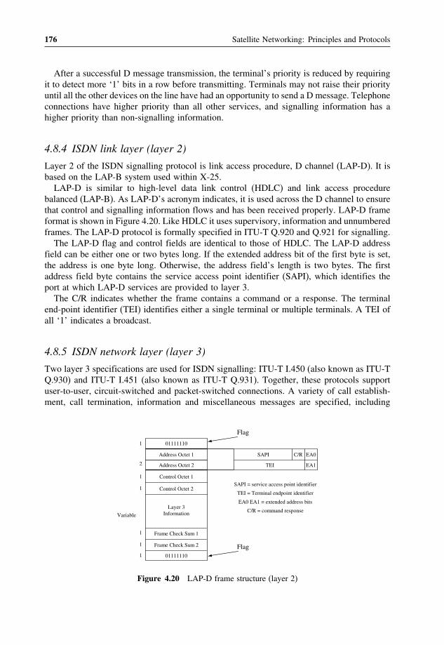
176 Satellite Networking: Principles and Protocols
After a successful D message transmission, the terminal’s priority is reduced by requiringit to detect more ‘1’ bits in a row before transmitting. Terminals may not raise their priorityuntil all the other devices on the line have had an opportunity to send a D message. Telephoneconnections have higher priority than all other services, and signalling information has ahigher priority than non-signalling information.
4.8.4 ISDN link layer (layer 2)
Layer 2 of the ISDN signalling protocol is link access procedure, D channel (LAP-D). It isbased on the LAP-B system used within X-25.LAP-D is similar to high-level data link control (HDLC) and link access procedure
balanced (LAP-B). As LAP-D’s acronym indicates, it is used across the D channel to ensurethat control and signalling information flows and has been received properly. LAP-D frameformat is shown in Figure 4.20. Like HDLC it uses supervisory, information and unnumberedframes. The LAP-D protocol is formally specified in ITU-T Q.920 and Q.921 for signalling.The LAP-D flag and control fields are identical to those of HDLC. The LAP-D address
field can be either one or two bytes long. If the extended address bit of the first byte is set,the address is one byte long. Otherwise, the address field’s length is two bytes. The firstaddress field byte contains the service access point identifier (SAPI), which identifies theport at which LAP-D services are provided to layer 3.The C/R indicates whether the frame contains a command or a response. The terminal
end-point identifier (TEI) identifies either a single terminal or multiple terminals. A TEI ofall ‘1’ indicates a broadcast.
4.8.5 ISDN network layer (layer 3)
Two layer 3 specifications are used for ISDN signalling: ITU-T I.450 (also known as ITU-TQ.930) and ITU-T I.451 (also known as ITU-T Q.931). Together, these protocols supportuser-to-user, circuit-switched and packet-switched connections. A variety of call establish-ment, call termination, information and miscellaneous messages are specified, including
Flag
Address Octet 1
01111110
Address Octet 2
Control Octet 1
Control Octet 2
Layer 3Information
Frame Check Sum 1
Frame Check Sum 2
01111110
C/RSAPI
TEI
EA0
EA1
SAPI = service access point identifier
TEI = Terminal endpoint identifier
EA0 EA1 = extended address bits
C/R = command response
1
2
1
1
1
1
1
Variable
Flag
Figure 4.20 LAP-D frame structure (layer 2)

Satellite Internetworking with Terrestrial Networks 177
TE LE LE TE
Time Time Time Time
Setup
Setup
Alerting Alerting
Connect
ConnectAck.
Connect
ConnectAck.
ISDN
User User
Pick-up
Dial tone
Dial digits
Ringing
Ringing
RemoveRinging
Pick-up
Figure 4.21 Illustration of the ISDN layer 3 signalling
SETUP, CONNECT, RELEASE, USER INFORMATION, CANCEL, STATUS and DIS-CONNECT. These messages are functionally similar to those provided by the X.25 protocol.Figure 4.21 shows the typical stages of an ISDN circuit switched call.
4.9 ISDN over satellite
Due to the availability of satellite networks, it is the natural to make use of satellite networksto extend the ISDN network for a global coverage. Though the ISDN does not restrict usingany particular transmission systems, it is important from a satellite radio engineering pointof view to investigate how satellite transmission systems differ from the traditional systemsrequired to support ISDN, how satellite transmission error performance affects ISDN, andhow propagation delay via satellite link affects operations of ISDN. It is the responsibility ofthe ITU-R SG 4 to define relevant requirements on conditions and performance for satellitelinks to carry ISDN channels and translate the ITU-T standards in terms that are significantfor the satellite portion of the overall ISDN connections.
4.9.1 ITU-T ISDN hypothetical reference connection (IRX)
The ISDN hypothetical reference connection (IRX) is defined in the ITU-T G.821 recom-mendation. It is used to specify the performance requirement of the major transmissionsegments of the overall end-to-end connection. The distance for reference of the overallend-to-end connections is 27 500 km, which is the longest possible connection along theearth surface between subscribers (at reference point T).Three basic segments are identified with distances that are expected to be typical distances
of the portion in the overall end-to-end connections in the context of IRX, which are allocated

178 Satellite Networking: Principles and Protocols
allowable performance degradation of 30%, 30% and 40% to low-, medium- and high-gradesegments.The 30% for the low-grade segment is shared by two sides of the connections from user
terminal to local exchange. Similarly, there are two medium-grade segments from localexchange to international exchange sharing the 30%. Satellite links of fixed satellite serviceshould be equivalent to half of the high-grade segment as 20%, if used in the end-to-endISDN connection.In terms of distance, the high-grade segment counts for 25 000 km and the low and medium
segments on one side of the connection count for 1250 km and on the other side 1250 km.Satellite link counts for 12 500 km, if used in the end-to-end ISDN connection.
4.9.2 ITU-R hypothetical reference digital path (HRDP) for satellite
ITU-R defined the hypothetical reference digital path (HRDP) in ITU-R S.521 to study theuse of a fixed satellite link in a part of the ISDN HRX defined by ITU-T. As shown inFigures 4.22 and 4.23, the HRDP should consist of one earth–satellite–earth link with possibly
DigitalMultiplexequipment
Modemequipment
DigitalMultiplexequipment
Modemequipment
IF/RFequipment
IF/RFequipment
Earth station Earth station
Satellite link HRDP
Figure 4.22 Hypothetical reference digital path (HRDP)
DigitalMultiplexequipment
Modemequipment
IF/RFequipment
DigitalMultiplexequipment
Modemequipment
IF/RFequipment
Earth station Earth station
Satellite link HRDP: 20% (12,500 km)
High grade: 40% (25,000 km)
Lowgrade15%
Lowgrade15%
Highgrade15%
Highgrade15%
(1,250 km) (1, 250 km)
Localexchange
Localexchange
Figure 4.23 HRDP in ITU-T IRX at 64 kbit/s

Satellite Internetworking with Terrestrial Networks 179
one or more inter-satellite links in the space segment and interface with the terrestrial networkappropriate to the HRDP. The HRDP should accommodate different types of access as singlechannel or TDMA, and allow for use of techniques such as digital speed interpolation (DSI)or low rate encoding (LRE) in the digital multiplex equipment.Additionally, the earth stations should include facilities to compensate for the effects
of satellite link transmission time variation introduced by satellite movements, which are ofparticular significance in digital transmission in the time domain such as PDH.ITU-R HRDP uses 12 500 km from the IRX to develop performance and availability objec-
tives. The distance has been defined by taking into account various satellite network configura-tions with a maximum single hop covering an equivalent terrestrial distance of approximately16 000 km. Consequently, in the majority of cases satellite is used in international segments ofthe connection with two landing points usually less than 1000 km from the users. In practice,satellite network landing points should be designed as close as possible to user terminals.
4.9.3 Performance objectives
Satellite networks to support ISDH should allow end-to-end-connections to meet the per-formance objectives defined by the ITU-T. The ITU-R has developed recommendations forsatellite to achieve the performance objectives in the end-to-end connections:
• The ITU-R S.614 on quality objectives for a 64 kbit/s ISDN circuit gives specificationrelated to the ITU-T G.821 (see Tables 4.1 and 4.2).
• The ITU-R S.1062 on error performance for an HDRP operating at or above the primaryrate gives specification related to the ITU-T G.826 (see Table 4.3).
4.9.4 Satellite network to ISDN interconnection scenarios
A satellite network interconnected to the ISDN should be capable of supporting all the ISDNservices. As a minimum the satellite network needs to support ISDN circuit mode bear
Table 4.1 Quality objectives for digital telephony and 64Kbit/s ISDN
Measurement conditions Digital (PCM) telephony (S.522) 64Kbit/s ISDN (S.522)Bit Error Rate (BER) Bit Error Rate (BER)
20% of any month(10 minutes mean value)
10−6 —
10% of any month(10 minutes mean value)
— 10−7
2% of any month(10 minutes mean value)
— 10−6
0.3% of any month(1 minute mean value)
10−3 —
0.05% of any month(1 second mean value)
10−4 —
0.03% of any month(1 second mean value)
— 10−3

180 Satellite Networking: Principles and Protocols
Table 4.2 Overall end-to-end and satellite HRDP error performance objectives for internationalISDN connections
Performanceclassification
Definition End-to-end objective Satellite HRDP objectives
Degrade seconds Minutes intervalswith BER > 10−6
(more than 4errors/minute)
< 10% < 2%
Severely erroredseconds
Minutes intervalswith BER > 10−3
< 02% < 003%
Errored seconds Minutes intervalswith one or moreerrors
< 8% < 16%
services, which requires adequate capacity for channels ranging from 64 kbit/s to 1920 kbit/splus either 16 or 64 kbit/s D channel. In addition, if the satellite networks are used fordata communications, it is logical to also support ISDN packet mode bear services. Thesatellite network should be able to support some of the ISDN supplementary services suchas sub-addressing, direct dialling, multiple subscriber numbers and close groups.The satellite network is often viewed as a part of the user network connection to ISDN
through a NT2 network termination. Figure 4.24 illustrates a single node distributed ISDNcustomer network. The ISDN may offer at T reference point a basic or primary rate interfacethrough network terminal NT1. NT2 forms part of the customer networks, typically usingVSAT system. The NT2 can be envisaged as the node of a distributed PABX, while the Sinterface represents the standard for the interface between the PABX terminal equipment.Figure 4.25 illustrates a multiple node distributed ISDN customer network. The satellite
is used to interconnect several private ISDN networks (nodes), each of which consists ofa earth station, a network termination NT1 and a few user terminals. In both scenarios,the private ISDN networks (nodes) are connected to a public ISDN network via a hub. Inthe case of VSAT, terminals can communicate with each other via the hub if it is a starconfiguration and with each other directly if it is a mesh configuration.
4.9.5 Routing plan
Before 1980 the ITU-T routing plan was based on a network with a hierarchical structure withdescending central transit (CT) levels. Since 1980, ITU-T has made a radical change in itsinternational routing plan. The new plan is a ‘free routing structure’, i.e. no hierarchical routingis required. It assumes that national telephone operators will maintain national hierarchicalnetworks. Obviously the change was brought about by the long reach of satellite networks withwhich international high-usage (HU) trunks can terminate practically anywhere in the territoryof a national telecommunication networks. Figure 4.26 illustrates the concepts of routing in atelecommunication network hierarchy with satellite link for the international connections. Ofcourse, satellite can be used to replace any connection in the hierarchy.In practice, the large majority of international telephone traffic is routed on direct circuits
(i.e., no intermediate switching point) between international switching centres (ISC).

Satellite Internetworking with Terrestrial Networks 181
Table 4.3 Overall end-to-end and satellite HRDP error performance objectives for digitalconnection at primary rate or above
Performanceclassification
Definition End-to-end objective Satellite HRDP objectives
Bit rate — 1.5 to 15Mbit/s 15 to 55Mbit/s 1.5 to 15Mbit/s 15 to 55Mbit/sBit per block — 2000–8000 4000–20000 2000–8000 4000–20000Errored seconds
(EES) ratio(SESR)
ES/t:
• SES: 1 s with one ormore errored blocks,and
• t: available timeduring fixedmeasurementinterval.
0.04 0.0075 0.014 0.0262
Severe Erroredseconds(EES) ratio(SESR)
ES/t:
• SES: 1 s with 30%errored blocks orone SeverelyDisturbed Period(SDP),
• SDP: 4 continuousblocks or 1 s withBER of 10−2
0.002 0.002 0.007 0.007
Backgroundblock errored(BBE) ratio(SESR)
BBE/b
• BBE: an erroredblock not occurringas a part of SES.
• b: total number ofblocks during fixedmeasurementinterval (excludingblocks during SESand unavailabletime)
3×10⁻⁴ 2×10⁻⁴ 105×10−4 07×10−4
Note: Higher possible rates can also be found in ITU0R S.1062, including 55–160Mbit/s and 160 to3500Mbit/s.
ITU-T E.171 provides the rules governing routing of connections consisting of a numberof circuits in tandem. These connections have an importance in the network because:
• They are used as alternate routes to carry overflow traffic in busy periods to increasenetwork efficiency.
• They can provide a degree of service protection in the event of failure of other routes.• They can facilitate network management when associated with the ISC having temporaryalternative routing capabilities.

182 Satellite Networking: Principles and Protocols
NT2 NT1Local ISDN
exchange
Earthstation
Earthstation
Earthstation
Earthstation
Terminalequipment
Terminalequipment
Terminalequipment
Terminalequipment
Sinterface
Sinterface
Tinterface
Customer network equipment Public ISDN network
Hub
Terminalequipment
Figure 4.24 Single node distributed ISDN customer network
Earthstation
Earthstation
Earthstation
S interface
Sinterface
Customer network equipment
NT2 NT1Local ISDN
exchange
Tinterface
Public ISDN network
Terminals
NT2Hub
NT2
NT2
Earthstation
Terminalequipment
Terminalequipment
Figure 4.25 Multiple nodes distributed ISDN customer network
The rules have been designed to preserve the freedom of network operators to route theiroriginating traffic directly or via any transit administration they choose, and to offer transitcapabilities to as wide a range of destinations as possible. The governing features of thisrouting plan include that:
• It does not have to be hierarchical.• Operators are free to offer whatever transit capabilities they wish, providing they conformto the recommendation.

Satellite Internetworking with Terrestrial Networks 183
International Transmission Network(Cable, satellite and radio)
InternationalExchange
MainNetwork
Exchange
Phone
Fax
Voicebanddata
Cordlessphone
Mobile
PBX
Phone
Fax
Voicebanddata
Cordlessphone
Mobile
ISDN
Notes: the use of satellites is similar to their use of leased networks. An addedcomplication which restricts their use is the need to carefully control circuitrouting through a switched network to minimise the chance of picking up 2satellite hops on a particular call.
InternationalExchange
MainNetwork
Exchange
LocalExchange
LocalExchange
Modem
PBX
Modem
Figure 4.26 Switching and routing concepts in the telecommunication networks
• Direct traffic should be routed over final (fully provided) or high usage circuit groups.• There are no more than four international circuits in tandem between the originating andterminating ISCs.
• Advantage should be taken of the non-coincidence of international traffic by the use ofalternative routings and provide route diversity (referring to ITU-T E.523).
• The routing of transit switched traffic should be planned to avoid possible circular routings.
When a circuit group has both terrestrial and the satellite circuits, the choice of routingshould be governed by:
• The guidance given in ITU-T G.114 (e.g., no more than 400ms one-way propagation time).• The number of satellite circuits likely to be utilised in the overall connection.• The circuit which provides the better transmission quality and overall service quality.• The inclusion of two or more satellite circuits (two or more hops over satellite) in thesame connection should be avoided in all but exceptional cases when the satellite is theonly possible link available for the connection.
4.10 Interworking with heterogeneous networks
Satellites offer a variety of means to accommodate different transmission rates includingbasic rate, primary rate and high speed IDR. Therefore, there is a significant differencebetween the interconnections of different networks.Satellite networks can be used as thin routes between pairs of earth stations, as access
networks to provide basic rate and primary rate and as transit networks to interconnect mainnetworks with a capacity measured in thousands of circuits.

184 Satellite Networking: Principles and Protocols
Transmission bit rate is the physical layer feature of the networks and is only oneaspect of interworking issues. There are also high layer protocol issues. Often interworkingunits have to be introduced to deal with differences of functions at higher layer protocolswhen interconnecting different type of networks. Here we will discuss some general issuesconcerning interworking with heterogeneous networks.
4.10.1 Services
Different services are available in heterogeneous networks. For example, video telephonyservice is supported by the ISDN network and ordinary telephony is supported by plaintelephony network. If a call is made from one to the other, the video information must beleft out for the connection to be successful. Voice services in the video telephony terminalshould be able to work as an ordinary telephone terminal because the ordinary telephonyservice is only a subset of video telephony. Another example is the conversion betweenemail and fax where the interworking functions are more complicated because differentterminals providing different services are involved.Some services do not always need to be able to internetwork with each other such as
file transfer, while some services may not be able to internetwork together at all. Normallyservice level internetwork defines the functional requirement to implement internetworkingfunctions for heterogeneous networks.
4.10.2 Addressing
In heterogeneous networks, addressing is an important issue to be considered. We have totry to maintain the independent different networking schemes. Each address used to identifya terminal in the network must be unique.Each internetworking unit of two networks should have two addresses, one of which is
used in one network and one for the other network. A mapping between terminals and theinternetworking unit must be available so that a terminal can make use of the internetworkingunit when trying to connect to a terminal in the other networks. A long-haul connection maytraverse many heterogeneous networks from source to destination of the connection.Typical types of address include: Internet address, local area network address (such as
Ethernet) and telephone network address (such as telephony number).
4.10.3 Routing
Routing is another important issue because the two networks can have significantly differenttransmission speeds, routing mechanisms, protocol functions and QoS requirements. There-fore, it is important to keep the routing independent within each network. The differencesthat the internetworking unit has to deal with include the protocol to access the networks,packet and frame format and size, and maintaining the QoS for the end-to-end connectionrequirement. In addition to the user information to be transported across different types ofnetworks, signalling and management also have to be considered.

Satellite Internetworking with Terrestrial Networks 185
Typical examples of heterogeneous routing can be found in the Internet and IP telephonyservices where end-to-end connections traverse across LAN, MAN, telephony, mobile andsatellite networks.
4.10.4 Evolution
Evolution is an important issue for all actors in the area of telecommunications because itpredicts the long-range future development of both the network and services. It is differ-ent from planning, which concentrates on precise tasks and gives information and detailedfigures on actions to be taken in the future. The driving force of evolution is technical andtechnological progress, which influence two main areas characterised by mutual interdepen-dences: change and growth. In addition, economic considerations and conditions stronglyinfluence evolution. One issue for future development is the transition from individual sub-networks with different capacities into a single overall network combining all componentsand offering even more facilities and capabilities.Due to flexibility and adaptability, satellite systems have been used in a wide range
of network topologies from simple point-to-point connections to complex multipoint-to-multipoint networks and transmission speeds from a few kbit/s to hundreds of Mbit/s. Inmany cases, satellite networks can present a alternative means of communication with respectto terrestrial networks, and bring advantages from both technical and economic viewpoints.The functions of satellite networks can be the same as a traditional transmission medium,
or provide advanced switching capabilities to work with all types of terrestrial networks.In an early phase of broadband networks, satellite can be used as a flexible transport mech-
anism to provide an effective means to link users who cannot be reached by the broadbandnetworks. For some users, satellites will provide an initial access to the broadband networks.Once the broadband network is well established, satellite can be used to complement the
terrestrial networks in areas where installation of other network technologies is difficult orexpensive, and to provide services such as broadcast and mobile services to cover the globe.To meet the challenge, satellite technologies are evolving, which exploit technological
advantage by using higher frequency band on-board switching technologies to provide mobileand broadcasting services.
Further reading[1] ITU-R Recommendation S.614-3, Allowable error performance for a hypothetical reference digital path in the
fixed-satellite service operating below 15GHz when forming part of an international connection in an integratedservices digital network, Question ITU-R 52/4, 1986-1990-1992-1994.
[2] ITU-R Recommendation S.1062-2, Allowable error performance for a hypothetical reference digital pathoperating at or above the primary rate, Question ITU-R 75/4, 1994-1995-1999.
[3] ITU-T Recommendation G.107, The E-model, a computational model for use in transmission planning, 03/2003.[4] ITU-T Recommendation G.108 Application of the E-model: a planning guide, 09/1999.[5] ITU-T Recommendation G.821, Error performance of an international digital connection cooperating at a bit
rate below the primary rate and forming part of an integrated services digital network, 08/1996.[6] ITU-T Recommendation G.826, Error performance parameters and objectives for international constant bit rate
digital paths at or above the primary rate, 02/1999.[7] ITU-T Recommendation I.351/Y.801/Y.1501, Relationships among ISDN, Internet protocol and GII perfor-
mance recommendations (1988, 1993, 1997, 2000), 01/2000.[8] ITU-T Recommendation I.525, Interworking between networks operating at bit rates less than 64 kbit/s with
64 kbit/s-based ISDN and B-ISDN, 08/1996.

186 Satellite Networking: Principles and Protocols
[9] ITU-T Recommendation Y.101 Global information infrastructure terminology: terms and definitions, 03/2000.[10] ITU-T Recommendation E.800, Terms and definitions related to quality of service and network performance
including dependability, 08/94.[11] ITU-T Recommendation G.702, Digital hierarchy data rates, 11/88.[12] ITU-T Recommendation G.703, Physical/electrical characteristics of hierarchical digital interfaces, 11/2001.[13] ITU-T Recommendation G.704, Synchronous frame structures used at 1544, 6312, 2048, 8448 and
44 736 kbits/s hierarchical levels, 10/98.[14] ITU-T Recommendation G.707/Y.1322, Network node interface for the synchronous digital hierarchy (SDH),
12/2003.[15] ITU-T Recommendation G.708, Sub STM-0 network node interface for the synchronous digital hierarchy
(SDH), 06/99.[16] ITU-T Recommendation G.709/Y.1331, Interfaces for the Optical Transport Network (OTN), 03/2003.[17] ITU-T Recommendation I.430, Basic user-network interface – layer 1 specification, 11/95.[18] ITU-T Recommendation I.431, Primary rate user-network interface – layer 1 specification, 03/93.[19] ITU-T Recommendation Q.920, ISDN user-network interface data link layer - General aspects, 03/93[20] ITU-T Recommendation Q.921, ISDN user-network interface - Data link layer specification, 09/97.[21] Recommendation Q.930, Digital subscriber signalling system No. 1 (DSS 1) – user-network interface layer 3 –
general aspects, 03/93[22] ITU-T Recommendation Q.931, ISDN user-network interface layer 3 specification for basic call control, 05/98.[23] ITU-R S.521-4, Hypothetical reference digital paths for systems using digital transmission in the fixed-satellite
service, 01/2000[24] ITU-R S.614-4, Allowable error performance for a satellite hypothetical reference digital path in the fixed-
satellite service operating below 15GHZ when forming part of an international connection in an integratedservices digital network, 02/05.
[25] ITU-R S.1062-2 - Allowable error performance for a satellite hypothetical reference digital path operatingbelow 15 GHZ, Draft Revision of Recommendation, 02/05.
[26] ITU-T G.114, One-way transmission time, 05/03.[27] ITU-T E.171, International telephone routing plan, 11/88.[28] ITU-T E.523, Standard traffic profiles for international traffic streams, 11/88.
Exercises
1. Explain the terms: interworking and internetworking.2. Use a sketch to explain the concept of reference configuration.3. Explain the ISDN reference points and function blocks.4. Explain the different network traffic in user plane, control plane and management
plane.5. Explain the network hypothetical reference connection and related performance
objectives for satellite.6. Explain the basic models and parameters of traffic engineering in telephony net-
works.7. Explain the principles of digital networks including PDH, SDH and ISDN.8. Explain different types of signalling schemes and their role in the network.9. Explain how to calculate the performance objectives of satellite networks in end-
to-end reference connections.10. Discuss the issues of SDH over satellite.11. Discuss the issues of ISDN over satellite.

5ATM over Satellite Networks
This chapter aims to provide an introduction to the concept of broadband satellite net-working based on ATM technology. Although ATM networking is evolving towards all-IPnetworking, we can see that the new-generation Internet networks have started to adopt thebasic principles and techniques developed for ATM networks to be able to support qualityof service (QoS), class of service (CoS), fast packet switching, traffic control and trafficmanagement. When you have completed this chapter, you should be able to:
• Know the design issues and concepts concerning ATM over satellites.• Know the GEO satellite ATM networking and advanced satellite networking withLEO/MEO constellations.
• Describe the architecture of broadband network interconnection and terminal access.• Describe the major roles of satellites in broadband networks with ATM over satellitenetworking.
• Understand the basic concept of satellite transparent and on-board switching payload forATM networks.
• Understand ATM QoS and performance issues and enhancement techniques for satelliteATM networks.
5.1 Background
In the early 1990s, research and development in broadband communications based on ATMand fibre optic transmission cable generated a significant demand for cost-effective intercon-nection of private and public broadband ATM LANs (also called ATM islands), experimentalATM networks and testbeds, and for cost-effective broadband access via satellite to thesebroadband islands. However, there was a shortage of terrestrial networks to provide broad-band connections in wide areas, particularly in more remote or rural areas where terrestrial
Satellite Networking: Principles and Protocols Zhili Sun© 2005 John Wiley & Sons, Ltd
188 Satellite Networking: Principles and Protocols
lines are expensive and uneconomical to install and operate. Satellite networking was con-sidered as an alternative solution to ‘broadband for all’ to complement terrestrial broadbandnetworks due to its flexibility and immediate global coverage. It was also expected to providedistribution and broadcasting services.In the commercial arena, the need to provide broadband networks over satellite was also
expected to increase significantly broadband services. Examples of the identified applicationsincluded linking remote office sites (e.g. oil rigs) to the enterprise backbone and providingbroadband entertainment services to mobile platforms (e.g. aeroplanes, ships). Other exam-ples included emergency and disaster relief scenarios and remote/rural medical care wherethe infrastructure was either disrupted or lacking.
5.1.1 Networking issues
One of the key networking issues was to provide interconnection and also access to geo-graphically dispersed broadband islands in the context of ATM networks with the requiredQoS and bandwidth. Due to their global coverage and broadcasting nature, satellite networkscan also be best used for broadband mobile and broadcasting services, where the major tech-nology challenge is how to design small satellite terminals at low cost but with high-speedtransmission for broadband services.The design of satellite ATM networks was also expected to be directly compatible with
the terrestrial networks. It is widely recognised that the development of B-ISDN based ATMwas not revolutionary but evolutionary. This also required satellite ATM networks to beable to interconnect the ATM networks as well as existing data networks such as the LANand MAN.Like other packet networks, ATM is a set of protocols using asynchronous transfer mode
to support broadband services; it is not a transmission technology, but can be transportedover different types of transmission technologies and media including wireless, cable andsatellite networks. It has been standardised by the ITU-T and the ITU-R to exploit thepotential of satellite ATM networks.By the late 1990s, the emerging WWW services and applications, based on the Inter-
net, changed the landscape of the telecommunications and data communications networksindustries. It became mandatory to support Internet protocol (IP) over ATM solutions, andalso made it difficult to support QoS. This also led to the convergence of user terminals,networks and services and applications in the telecoms industry and Internet towards thenext generation of Internet by taking advantage of both the IP and ATM networks.
5.1.2 Satellite services in the B-ISDN networking environment
The principal advantages of satellite systems are their wide coverage and broadcastingcapabilities. There are enough satellites to provide broadband connections anywhere in theworld. The cost and complexity are independent of distance. There are clear advantages toextend the broadband capabilities to rural and remote areas. Satellite links are quick andeasy to install with fewer geographical constraints. They make long-distance connectionsmore cost-effective within the coverage areas, particularly for point-to-multipoint and broad-casting services. Satellites can also be complementary to the terrestrial networks and mobilenetworks.

ATM over Satellite Networks 189
In a broadband networking environment, satellite networking can be used for user accessmode and also for network transit mode. In the user access mode, the satellite system ispositioned at the border of the broadband network. It provides access links to a large numberof users directly or via local networks. The interfaces to the satellite system in this mode are
UNI
NNI
ATMSwitch
ATMSwitch
PrivateUNI
Terminal
PublicUNI
PivateNNI
ATMSwitch
ATMSwitch
ATMSwitch
PublicNNI
PublicNetwork
Figure 5.1 Example of user access mode via satellite ATM network
ATMSwitch
ATMSwitch
ATMSwitch
ATMSwitch
ATMSwitch
ATMSwitch
PublicNNI
NNI
PublicNNI
PublicNetwork
PublicNetwork
B-ICI
Figure 5.2 Example of network transit mode via a satellite ATM network

190 Satellite Networking: Principles and Protocols
of the user network interface (UNI) type on one side and the network node interface (NNI)type on the other side.In the network transit mode, the satellite systems provide high bit-rate links to interconnect
the B-ISDN network nodes or network islands. The interfaces on both sides are NNI type.Figure 5.1 illustrates an example of a configuration of the satellite system for broadbandnetwork access and mobile access and Figure 5.2 shows the interconnection of broadbandislands/networks.
5.2 Design issues of satellite ATM systems
The satellite networks are fundamentally different from terrestrial networks in terms of delay,error and bandwidth characteristics, and can have an adverse impact on the performance ofATM traffic, congestion control procedures and transport protocol operations.
5.2.1 Propagation delay
The propagation delay for the packets of a connection consists of the following threequantities: from the source ground terminal to satellite uplink propagation delay (tup);the inter-satellite link propagation delays (ti) (if ISL are used); and from the satellite todestination ground terminal downlink propagation delay (tdown).The uplink and downlink satellite–ground terminal propagation delays (tup and tdown,
respectively) represent the time taken for the signal to travel from the source ground terminalto the first satellite in the network (tup), and the time taken for the signal to reach thedestination ground terminal from the last satellite in the network (tdown). They can becalculated as the following:
tup =distance_from_source_terminal_to_satellite
speed_of_light
tdown =distance_from_satellite to destination_terminal
speed_of_light
The end-to-end delay also depends on LEO/MEO constellation designs. In contrast toGEO satellites, the LEO uplink and downlink propagation delay is much shorter but variableover time.We can also note the transmission delay as tt, the inter-satellite link delay as ti, the
on-board switching and processing delay as ts, the buffering delay as tq and delay due to theterrestrial networks (terrestrial tail) as tn. The inter-satellite, on-board switching, processingand buffering delays are cumulative over the path traversed by a connection. The delayvariation is caused by orbital dynamics, buffering, adaptive routing (in LEO) and on-boardprocessing. Then, the end-to-end delay (D) can be calculated as:
D = tt + tup+ ti+ tdown+ ts + tq + tn

ATM over Satellite Networks 191
The transmission delay (tt) is the time taken to transmit a single data packet at the networkdata rate as:
tt =packet_sizedata_rate
For broadband networks with high data rates, the transmission delays become negligiblein comparison to the satellite propagation delays. For example, it only takes about 212microseconds to transmit an ATM cell at a 2Mbit/s link. This delay is much less than thepropagation delays in satellites. Compared with the propagation delays, all the ti ts tq andtn are very small, hence can be neglected in calculation.The inter-satellite link delay (ti) is the sum of the propagation delays of the inter-satellite
links (ISL) traversed by the connection. It may be in-plane or cross-plane links. In-planelinks connect satellites within the same orbit plane, while cross-plane links connect satellitesin different orbit planes. In GEO systems, ISL delays can be assumed to be constant over aconnection’s lifetime because GEO satellites are almost stationary over a given point on theearth, and with respect to one another. In LEO constellations, the ISL delays depend on theorbital radius, the number of satellites per orbit, and the inter-orbital distance (or the numberof orbits). All in-plane links in circular orbits are considered to be constant. Cross-plane ISLdelays change over time, break at highest latitudes and must be reformed. As a result, LEOsystems can exhibit a high variation in ISL delay.LEO satellites have lower propagation delays due to their lower altitudes, but many
satellites are needed to provide a global service. While LEO systems have lower propagationdelays, they exhibit higher delay variation due to connection handovers and other factorsrelated to orbital dynamics.The large delays in GEO, and delay variations in LEO, affect both real-time and non-real-
time applications. Many real-time applications are sensitive to the large delay experiencedin GEO systems, as well as to the delay variation experienced in LEO systems. In anacknowledgement and time-out based congestion control mechanism, performance is inher-ently related to the delay–bandwidth product of the connection. Moreover, round trip time(RTT) measurements are sensitive to delay variations that may cause false time-outs andretransmissions for acknowledgement-based data services. As a result, the congestion controlissues for broadband satellite networks are somewhat different from those of low-latencyterrestrial networks. Both interoperability as well as performance issues between satelliteand terrestrial networks must be addressed before data, voice and video services can beprovided over satellite networks.
5.2.2 Attenuation and constraints
The attenuation of free space (called free-space loss, LFS) represents the ratio of receivedand transmitted power in a link between two isotropic antennas:
LFS = 4R/2
Where R is propagation distance and is wavelength. A GEO satellite and a station situatedexactly under the satellite is 35 786 km between the satellite and the station (equal to the

192 Satellite Networking: Principles and Protocols
altitude of the satellite). Therefore the LFS is of the order of 200 dB at C band and 207 dBat Ku band. Attenuation is also affected by other effects such as rain, clouds, snow, ice andgas in the atmosphere.Satellite communication bandwidth being a limited resource will continue to be a precious
asset. Achieving availability rates of 99.95% at very low bit error rate (BER) is costly.Lowering required availability rates by even 0.05% dramatically lowers satellite link costs.An optimum availability level must be a compromise between cost and performance.There are constraints in general in choosing the satellite link parameters due to regulations,
operational constraints and propagation conditions. The regulations are administered by theITU-R, ITU-T and ITU-D. They define space radio-communication services in terms oftransmission and/or reception of radio waves for specific telecommunication applications.The concept of a radio communication service is applied to the allocation of frequencybands and analysis of conditions for sharing a given band among compatible services. Theoperational constraints relate to realisation of a C/N0 ratio, provision of an adequate satelliteantenna beam for coverage of a service area with a specified value of satellite antenna gain,level of interference between satellite systems, orbital separation between satellites operatingin identical frequency bands and minimum of total cost.Therefore the design of high-speed transmission faces great challenges to achieve error
performance objectives.
5.3 The GEO satellite ATM networking architecture
In this section, the discussion on GEO satellite ATM networking architecture is based on thedesign of the CATALYST project. The CATALYST project was funded within the EuropeanFramework Programme Research in Advanced Communication in Europe phase II (RACEII) to develop an experimental broadband satellite ATM network for interconnection togeographically dispersed broadband networks called ‘broadband islands’. The CATALYSTdemonstration took place in 1992–3 and involved the first transmission of ATM cells oversatellite in Europe.A modular approach was used in the design to interface different networks and the satellite,
converting network packets to and from ATM cells. The functions of the main buildingblocks of the demonstrator are described here.
5.3.1 The ground segment
To make use of the existing satellite systems, development has been mainly on the groundsegment. Many modules were developed, where each module had buffer(s) for packet/cellconversion and/or traffic multiplexing. The buffers are also used for absorbing high-speedburst traffic.Therefore, the satellite ATM system can be designed to be capable of interconnecting
different networks with capacities in the range of 10 to 150Mbit/s (10Mbit/s for Ethernet,34Mbit/s for DQDB, 100Mbit/s for FDDI and 150Mbit/s for ATM networks). Figure 5.3illustrates the model of the ground equipment. A brief description of these modules is alsogiven in the following.

ATM over Satellite Networks 193
FDDI
Ethernet
DQDB
ATM ATM-LT
DQDB-AM
F-LAM
E-LAM
ATM-AM TIM-ATMRF
Equip.
GLAC
155 Mbit/s
100 Mbit/s
34 Mbit/s
10 Mbit/s
24 Mbit/s
34.368 Mbit/s
20.352 Mbit/s
Figure 5.3 Ground-segment modules
• The ATM-LT provides an interface with a speed of 155Mbit/s between the ATM networkand the ground-station ATM equipment. It is also the termination point of the ATMnetwork and passes the ATM cells to the ATM adaptation module (ATM-AM).
• The Ethernet LAN adaptation module (E-LAM) provides an interface to the Ethernet localarea network.
• The FDDI LAN adaptation module (F-LAM) provides an interface to the FDDI network.• The generic LAN ATM converter (GLAC) module converts the FDDI and Ethernet packetsinto ATM cells, then passes the cells to the ATM-AM module.
• The DQDB adaptation module (DQDB-AM) provides an interface to the DQDB networkwith a small buffer. It converts DQDB packets into ATM cells and then passes them tothe ATM-AM.
• The ATM-AM is an ATM adapter. It multiplexes the ATM cell streams from the twoports into one ATM cell stream. This module passes the cells to the terrestrial interfacemodule for ATM (TIM-ATM) and provides an interface between the terrestrial networkand the satellite ground-station.
• The TIM-ATM has two buffers with a ‘ping-pong’ configuration. Each buffer can storeup to 960 cells. The cells are transmitted from one buffer while the ATM-AM feeds thecells into the other buffer. Transmissions of the buffers are switched every 20ms.
5.3.2 The space segment
In the demonstrator system, the EUTELSAT II satellite was used in good weather conditionsmaking use of 36MHz bandwidth of a transponder. It achieved transmission capacity ofapproximately 20Mbit/s. The capacity has to be shared by a number of earth stations whenmultiple broadband islands are interconnected. It was a trade-off to provide good requiredQoS and efficient utilisation of the satellite resources (bandwidth and transmission power).

194 Satellite Networking: Principles and Protocols
Compared to the propagation delay, the delay within the ground segment was insignificant.Buffering in the ground-segment modules could cause variation of delay, which was affectedby the traffic load on the buffer. Most of the variation was caused in the TIM-ATM buffer.It caused an estimated average delay of 10ms and worst-case delay of 20ms. Cell lossoccurred when the buffer overflowed. The effects of delay, delay variation and cell loss inthe system could be controlled to the minimum by controlling the number of applications,the amount of traffic load and allocating adequate bandwidth for each application.
5.3.3 Satellite bandwidth resource management
The TDMA system was used with frame length of 20ms which was shared by the earthstations. Each earth station was limited to the time slots corresponding to the allocatedtransmission capacity up to maximum 960 cells (equivalent to 20.352Mbit/s). The generalTDMA format is shown in Figure 5.4.There are three levels of resource management (RM) mechanisms. The first level is
controlled by the network control centre (NCC) and allocates the bandwidth capacity to eachearth station. The allocation is in the form of burst time plans (BTP). Within each BTP,burst times are specified for the earth station, which limit the number of cells in bursts theearth stations can transmit. In the CATALYST demonstrator, the limit is that each BTP isless than or equal to 960 ATM cells and the sum of the total burst times is less than or equalto 1104 cells.The second level is the management of the virtual paths (VPs) within each BTP. The
bandwidth capacity that can be allocated to the VP is restricted by the BTP. The third levelis the management of the virtual channels (VCs). It is subject to the available bandwidthresource of the VP. Figure 5.5 illustrates the resource management mechanisms of thebandwidth capacity. Each station is allocated a time slot within the burst time plan. Each timeslot is further divided to be allocated according to the requirements of VPI and VCI. Theallocation of the satellite bandwidth is done when the connections are established. Dynamicchanging, allocation, sharing, or re-negotiation of the bandwidth during the connection isfor further study.
Preamble ATM cells
TDMA frame of 20 ms
Station 1 Station 2 Station N......
Guardtime
Carrier & clockrecovery pattern
Burst start &identifications
Engineeringservice channel
Figure 5.4 TDMA frame format (earth station to satellite)

ATM over Satellite Networks 195
Burst Time Plan
Station 1 Station 2 Station N......
VC1 VC2 VC3
VP3VP2
VC1 VC2 VC3 VC1 VC2 VC3
VP1
Figure 5.5 Satellite resource management
To effectively implement resource management, the allocation of the satellite link band-width can be mapped into the VP architecture in the ATM networks and each connectionmapped into the VC architecture. The BTP can be a continuous burst or a combination of anumber of sub-burst times from the TDMA frame.The burst-time plan, data arrival rate and buffer size of the ground station have an
important impact on the system performance. To avoid buffer overflow the system needs tocontrol the traffic arrival rate, burst size or allocation of the burst-time plan. The maximumtraffic rate allowed, to prevent the buffer overflow, is a function of the burst-time plan andburst size for a given buffer size, and the cell loss ratio is a function of traffic arrival rateand allocated burst-time plan for a given buffer size.
5.3.4 Connection admission control (CAC)
CAC is defined as the set of actions taken by the network at the call set-up phase in order toestablish if sufficient resources are available to establish the call through the whole networkat its required QoS and maintain the agreed QoS of existing calls. This also applies tore-negotiation of connection parameters within a given call. In a B-ISDN environment, acall can require more than one connection for multimedia or multiparty services such asvideo-telephony or videoconference.A connection may be required by an on-demand service, or by permanent or reserved
services. The information about the traffic descriptor and QoS is required by the CACmechanism to determine whether the connection can be accepted or not. The CAC in thesatellite has to be the integrated part of the whole-network CAC mechanisms.
5.3.5 Network policing functions
Networking policing functions make use of usage parameter control (UPC) and networkparameter control (NPC) mechanisms. UPC and NPC monitor and control traffic to protectthe network (particularly the satellite link) and enforce the negotiated traffic contract duringthe call. The peak cell rate has to be controlled for all types of connections. Other trafficparameters may be subject to control such as average cell rate, burstiness and peak duration.

196 Satellite Networking: Principles and Protocols
At cell level, cells are allowed to pass through the connection if they comply with thenegotiated traffic contract. If violations are detected, actions such as cell tagging or discardingare taken to protect the network.Apart from UPC/NPC tagging users may also generate different priority traffic flows by
using the cell loss priority bit. This is called priority control (PC). Thus, a user’s low-prioritytraffic may not be distinguished by a tagged cell, since both user and network use thesame CLP bit in the ATM header. Traffic shaping can also be implemented in the satelliteequipment to achieve a desired modification of the traffic characteristics. For example, itcan be used to reduce peak cell rate, limit burst length and reduce delay variation by suitablyspacing cells in time.
5.3.6 Reactive congestion control
Although preventive control tries to prevent congestion before it actually occurs, the satellitesystem may experience congestion due to the earth-station multiplexing buffer or switchoutput buffer overflow. In this case, where the network relies only on the UPC and nofeedback information is exchanged between the network and the source, no action can betaken once congestion has occurred. Congestion is defined as the state where the networkis unable to meet the negotiated QoS objectives for the connections already established.Congestion control (CC) is the set of actions taken by the network to minimise the intensity,spread and duration of congestion. Reactive CC becomes active when there is indication ofany network congestion.Many applications, mainly those handling data transfer, have the ability to reduce their
sending rate if the network requires them to do so. Likewise, they may wish to increase theirsending rate if there is extra bandwidth available within the network. These kinds of applica-tions are supported by the ABR service class. The bandwidth allocated for such applicationsis dependent on the congestion state of the network. Rate-based control is recommended forABR services, where information about the state of the network is conveyed to the sourcethrough special control cells called resource management (RM) cells. Rate information canbe conveyed back to the source in two forms:
• Binary congestion notification (BCN) using a single bit for marking the congested andnot congested states. BCN is particularly attractive for satellites due to their broadcastcapability.
• Explicit rate (ER) indication is used by the network to notify the source the exact bandwidthit should use to avoid congestion.
The earth stations may determine congestion status either by measuring the traffic arrivalrate or by monitoring the buffer status.
5.4 Advanced satellite ATM networks
Until the launch of the first regenerative INTELSAT satellite in January 1991, all satelliteswere transparent satellites. Although the regenerative, multibeam and on-board ATM switchsatellites have potential advantages, they increased the complexity on reliability, the effecton flexibility of use, the ability to cope with unexpected changes in traffic demand (both

ATM over Satellite Networks 197
volume and nature) and new operation procedures. Advanced satellite ATM networks tried toexplore the benefit of on-board processing and switching, multibeam satellite and LEO/MEOconstellation, although complexity is still the main concern for satellite payloads.
5.4.1 Radio access layer
The radio access layer (RAL) for satellite access must take into account the performancerequirements for GEO satellites. A frequency-independent specification is preferred. Param-eters to be specified include range, bit rates, transmit power, modulation/coding, framingformats and encryption. Techniques for dynamically adjusting to varying link conditions andcoding techniques for achieving maximum bandwidth efficiencies need to be considered.The medium access control (MAC) protocol is required to support the shared use of the
satellite channels by multiple switching nodes. A primary requirement for the MAC protocolis to ensure bandwidth provisioning for all the traffic classes, as identified in UNI. Theprotocol should satisfy both the fairness and efficiency criteria.The data link control (DLC) layer is responsible for the reliable delivery of ATM cells
across the GEO satellite link. Since higher layer performance is extremely sensitive to cellloss, error control procedures need to be implemented. Special cases for operation oversimplex (or highly bandwidth asymmetric) links need to be developed. DLC algorithmstailored to special specific QoS classes also need to be considered.Wireless control is needed for support of control plane functions related to resource control
and management of the physical, MAC and DLC layers specific to establishing a wirelesslink over GEO satellites. This also includes meta-signalling for mobility support.
5.4.2 On-board processing (OBP) characteristics
OBP is in itself a vast domain that is the subject of much activity in the USA, Japan andEurope. All commercial civil satellites to date have used transparent transponders, whichconsist of nothing more than amplifiers, frequency changers and filters. These satellites adaptto changing demands, but at the cost of high space segment tariffs and high-cost, complexearth terminals. OBP aims to put the complexity in the satellite and to reduce the cost of theuse of the space segment and the cost of the earth terminals. There are varying degrees ofprocessing on board satellites:
• regenerative transponder (modulation and coding);• on-board switching;• access format conversion (e.g. FDMA-TDM); and• flexible routing.
They may not all be present in one payload and the exact mix will depend on applications.The advantages rendered by the use of OBP are as summarised:
• Regenerative transponders: the advantage of the regenerative scheme is that the uplinksand downlinks are now separated and can be designed independently of each other. Withconventional satellites (C/N)U and (C/N)D is additive; with regenerative transponders

198 Satellite Networking: Principles and Protocols
they are separated. This can be translated into an improved BER performance as reduceddegradation is now present. Regenerative transponders can withstand much higher levelsof interference for the same overall (C/N)T.• Multirate communications: with OBP it is possible to convert on the satellite betweenlow- and high-rate terminals. This allows ground terminals operating at various ratesto communicate with each other via a single hop. Transparent transponders require rateconversion terrestrially and hence necessitate two hops. Multirate communications impliesboth multicarrier demodulators and baseband switches.
These add up to much reduced complexity and cheaper ground terminals.
5.4.3 The ATM on-board switch
There are potential advantages in performance and flexibility for the support of servicesby placing switching functions on board satellites. It is particularly important for satelliteconstellations with spot beam coverage and/or inter-satellite communications, as it allowsbuilding networks upon constellation satellites therefore relying less on ground infrastructure.Figure 5.6 illustrates the protocol stack on board satellite and on the ground.In the case of ATM on-board switch satellites, the satellite acts as a switching point within
the network (as illustrated by Figure 5.6) and is interconnected with more than two terrestrialnetwork end points. The on-board switch routes ATM cells according to the VPI/VCI ofthe header and the routing table when connections are set up. It also needs to support thesignalling protocols used for UNI as access links and for NNI as transit links.On-board switching (OBS) satellites with high-gain multiple spot beams have been consid-
ered as key elements of advanced satellite communications systems. These satellites supportsmall, cost-effective terminals and provide the required flexibility and increased utilisationof resources in a burst multimedia traffic environment.
ATM layer
Physical layer
ATM layer
Physical layer
ATMon-boardswitch
Demod Remod
ATM layer
Physical layer
ATMon-boardswitch
Demod Remod
ATM layer
Physical layer
Figure 5.6 Satellite with ATM on-board switch

ATM over Satellite Networks 199
Although employing an on-board switch function results in more complexity on board thesatellite, the following are the advantages of on-board switches.
• Lowering the ground-station costs.• Providing bandwidth on demand with half the delay.• Improving interconnectivity.• Offering added flexibility and improvement in ground-link performance, i.e. this allowsearth stations in any uplink beam to communicate with earth stations in any downlinkbeam while transmitting and receiving only a single carrier.
One of the most critical design issues for on-board processing satellites is the selectionof an on-board baseband switching architecture. Four typical types of on-board switches areproposed:
• circuit switch;• fast packet switch (can be variable packet length);• hybrid switch;• ATM cell switch (fixed packet length).
These have some advantages and disadvantages, depending on the services to be carried,which are summarised in Table 5.1.From a bandwidth efficiency point of view, circuit switching is advantageous under the
condition that the major portion of the network traffic is circuit switched. However, for bursttraffic, circuit switching results in a lot of wasted bandwidth capacity.Fast packet switching may be an attractive option for a satellite network carrying both
packet-switched traffic and circuit-switched traffic. The bandwidth efficiency for circuit-switched traffic will be slightly less due to packet overheads.In some situations, a mixed-switch configuration, called a hybrid switch consisting of
both circuit and packet switches, may provide optimal on-board processor architecture.However, the distribution of circuit- and packet-switched traffic is unknown, which makesthe implementation of such a switch a risk.For satellite networking, fixed-size fast packet switching, such as ATM cell switching, is an
attractive solution for both circuit- and packet-switched traffic. Using statistical multiplexingof cells, it could achieve the highest bandwidth efficiency despite a relatively large headeroverhead per cell.In addition, due to on-board mass and power-consumption limitations, packet switching is
especially well suited to satellite switching because of the sole use of digital communications.It is important that satellite networking follows the trends of terrestrial technologies forseamless integration.
5.4.4 Multibeam satellites
A multibeam satellite features several antenna beams which provide coverage of differentservice zones as illustrated by Figure 5.7. As received on board the satellite, the signalsappear at the output of one or more receiving antennas. The signals at the repeater outputsmust be fed to various transmitting antennas.

200 Satellite Networking: Principles and Protocols
Table 5.1 Comparison of various switching techniques
Switchingarchitecture
Circuit switching Fast packet switching Hybrid switching Cell switching (ATMswitching)
Advantages • Efficientbandwidthutilisation forcircuit-switchedtraffic
• Efficient ifnetwork doesnot requirefrequent trafficreconfiguration
• Easy to controlcongestion bylimiting accessinto the network
• Self-routing• Does not require
control memory forrouting
• Transmissionwithoutreconfiguring of theon-board switchconnection
• Easy to implementautonomous privatenetworks
• Provides flexibilityand efficientbandwidthutilisation forpacket-switchedtraffic
• Can accommodatecircuit-switchedtraffic
• Handles a muchmore diverserange of traffic
• Optimisationbetween circuitswitching andpacket switching
• Lower complexityon board than fastpacket switch
• Can providededicatedhardware for eachtraffic type
• Self-routing with asmall VC/VP
• Does not requirecontrol memory forrouting
• Transmissionwithoutreconfiguringon-board switchconnection
• Easy to implementautonomous privatenetworks
• Provides flexibilityand efficientbandwidthutilisation for alltraffic sources
• Can accommodatecircuit-switchedtraffic
• Speed comparableto Fast packetswitching
Disadvantages • Reconfiguration ofearth stationtime/frequencyplans for eachcircuit set up
• Fixed bandwidthassignment (notflexible)
• Very inefficientbandwidthutilisation whensupportingpacket-switchedtraffic
• Difficult toimplementautonomousprivate networks
• For circuit-switchedtraffic higheroverheads thancircuit switchingdue to packetheaders.
• Contention andcongestion mayoccur
• Cannot maintainmaximumflexibility forfuture servicesbecause the futuredistribution ofsatellite circuitand packet trafficis unknown
• Waste of satelliteresources in orderto be designed tohandle the fullcapacity ofsatellite traffic
• For circuit-switchedtraffic somewhathigher overheadsthan packetswitching due to 5byte ATM header.
• Contention andcongestion mayoccur
The spot-beam satellites provide advantages to the earth-station segment by improvingthe figure of merit G/T on the satellite. It is also possible to reuse the same frequency bandseveral times in different spot beams to increase the total capacity of the network withoutincreasing the allocated bandwidth. However, there is interference between the beams.

ATM over Satellite Networks 201
Figure 5.7 Multibeam satellite
One of the current techniques for interconnections between coverage areas is on-boardswitching-satellite-switched TDMA (SS/TDMA). It is also possible to have packet-switchingon-board multibeam satellites.
5.4.5 LEO/MEO satellite constellations
One of the major disadvantages of GEO satellites is caused by the distance between the satel-lites and the earth stations. They have traditionally mainly been used to offer fixed telecom-munication and broadcast services. In recent years, satellite constellations of low/mediumearth orbit (LEO/MEO) for global communication have been developed with small terminalsto support mobility. The distance is greatly reduced. A typical MEO satellite constellationsuch as ICO has 10 satellites plus two spares, and an LEO such as SKYBRIDGE has 64satellites plus spares.Compared to GEO networks, LEO/MEO networks are much more complicated, but provide
a lower end-to-end delay, less free-space loss and higher overall capacity. However, dueto the relatively fast movement of satellites in LEO/MEO orbit relative to user terminals,satellite handover is an important issue.Constellations of LEO/MEO satellites can also be an efficient solution to offer highly
interactive services with a very short round-trip propagation time over the space segment(typically 20/100ms for LEO/MEO as compared to 500ms for geostationary systems). Thesystems can offer similar performances to terrestrial networks, thus allowing the use ofcommon communication protocols and applications and standards.
5.4.6 Inter-satellite links (ISL)
The use of ISL for traffic routing has to be considered. It must be justified that this technologywill bring a benefit, which would make its inclusion worthwhile or to what extent on-boardswitching, or some other form of packet switching, can be incorporated into its use.

202 Satellite Networking: Principles and Protocols
The issues that need to be discussed when deciding on the use of ISL include:
• networking considerations (coverage, delay, handover);• the feasibility of the physical link (inter-satellite dynamics);• the mass, power and cost restrictions (link budget).
The mass and power consumption of ISL payloads are factors in the choice of whetherto include them in the system, in addition to the possible benefits and drawbacks. Alsothe choice between RF and optical payloads is now possible because optical payloads havebecome more reliable and offer higher link capacity. The tracking capability of the payloadsmust also be considered, especially if the inter-satellite dynamics are high. This may be anadvantage for RF ISL payloads.Advantages of ISLs can be summarised as the following:
• Calls may be grounded at the optimal ground station through another satellite for calltermination, reducing the length of the terrestrial ‘tail’ required.
• A reduction in ground-based control may be achieved with on-board baseband switching –reducing delay (autonomous operation).
• Increased global coverage – oceans and areas without ground stations.• Single network control centre and earth station.
Disadvantages of ISLs can be summarised as the following:
• Complexity and cost of the satellites will be increased.• Power available for the satellite/user link may be reduced.• Handover between satellites due to inter-satellite dynamics will have to be incorporated.• Replenishment strategy.• Frequency coordination.• Cross-link dimensioning.
5.4.7 Mobile ATM
Hand-off control is a basic mobile network capability that allows for the migration ofterminals across the network backbone without dropping an ongoing call. Because of thegeographical distances involved, hand-off for access over GEO satellite is expected not tobe an issue in most applications. In some instances, for example intercontinental flights, aslow hand-off between GEO satellites with overlapping coverage areas will be required.Location management refers to the capability of one-to-one mapping between mobile
node ‘name’ and current ‘routing-id.’ Location management primarily applies to the scenarioinvolving switching on board the satellite.
5.4.8 Use of higher frequency spectrum
Satellite constellations can use the Ku band (11/14GHz) for connections between userterminals and gateways. High-speed transit links between gateways will be established usingeither the Ku or the Ka band (20/30GHz).

ATM over Satellite Networks 203
According to the ITU radio regulation, GEO satellite networks have to be protected fromany harmful interference from non-geostationary systems. This protection is achieved throughangular separation using a predetermined hand-over procedure based on the fact that the posi-tions of geostationary and constellation satellites are permanently known and predictable.When the angle between a gateway, the LEO/MEO satellite in use by the gateway andthe geostationary satellite is smaller than one degree, the LEO/MEO transmissions are stoppedand handed over to another LEO/MEO satellite, which is not in similar interference conditions.The constellations provide a cost-effective solution offering a global access to broadband
services. The architectures are capable of: supporting a large variety of services; reducingcosts and technical risks related to the implementation of the system; ensuring a seamlesscompatibility and complement with terrestrial networks; providing flexibility to accommo-date service evolution with time as well as differences in service requirements across regions;and optimising the use of the frequency spectrum.
5.5 ATM performance
ITU (ITUT-I356) defines parameters for quantifying the ATM cell transfer performance ofa broadband ISDN connection. This ITU recommendation includes provisional performanceobjectives for cell transfer, some of which depend on the user’s selection of QoS class.
5.5.1 Layered model of performance for B-ISDN
ITU (ITUT-I356) defines a layered model of performance for B-ISDN, as shown in Figure 5.8.It can be seen that the network performance (NP) provided to B-ISDN users depends on
the performance of three layers:
• The physical layer, which may be based on plesiochronous digital hierarchy (PDH),synchronous digital hierarchy (SDH) or cell-based transmission systems. This layer isterminated at points where the connection is switched or cross-connected by equipmentusing the ATM technique, and thus the physical layer has no end-to-end significance whensuch switching occurs.
• The ATM layer, which is cell-based. The ATM layer is physical media and applicationindependent and is divided into two types of sublayer: the ATM-VP layer and the ATM-VC layer. The ATM-VC layer always has end-to-end significance. The ATM-VP layerhas no user-to-user significance when VC switching occurs. ITUT-I356 specifies networkperformance at the ATM layer, including the ATM-VC layer and ATM-VP layer.
• The ATM adaptation layer (AAL), which may enhance the performance provided by theATM layer to meet the needs of higher layers. The AAL supports multiple protocol types,each providing different functions and different performance.
5.5.2 ATM performance parameters
ITUT-I356 also defines a set of ATM cell transfer performance parameters using thecell transfer outcomes. All parameters may be estimated on the basis of observations

204 Satellite Networking: Principles and Protocols
Satellite Networking: principles and protocols
1 3/4 5
T1316560-99
NP for AAL Type 1
NP for AAL Type 2
NP for AAL Type 3/4
NP for AAL Type 5
Network Performancefor VC – ITU-T I.356
AAL
ATM-VC layer
ATM-VP layer
physical layer(PL)
PL PL
ATM-VP layer
ATM-VC layer
VP
PL PL
VP
Network Performancefor VP – ITU-T I.356
Network Performancefor VP – ITU-T I.356
VP Switch or cross-connectusing ATM transfer mode
VC Switch or cross-connectusing ATM transfer mode
Physical layer(ITU-T G.826
allocated – Note)
NOTE – The need for additional physical layer performance parameters and objectives is under study.
2 1 3/4 5
AAL
ATM-VC layer
ATM-VP layer
physical layer(PL)
2
Figure 5.8 Layered model of performance for B-ISDN (ITUT-1356) (Reproduced with the kindpermission of ITU.)
at the measurement points (MPs). Following is a summary of ATM performanceparameters:
• Cell error ratio (CER) is the ratio of total errored cells to the total of successfully trans-ferred cells, plus tagged cells, plus errored cells in a population of interest. Successfullytransferred cells, tagged cells and errored cells contained in severely errored cell blocksare excluded from the calculation of the cell error ratio.
• Cell loss ratio (CLR) is the ratio of total lost cells to total transmitted cells in a populationof interest. Lost cells and transmitted cells in severely errored cell blocks are excludedfrom the calculation of the cell loss ratio. Three special cases are of interest, CLR0,CLR0+1 and CLR1, considering the CLR tag in the ATM cell header.
• Cell misinsertion rate (CMR) is the total number of misinserted cells observed during aspecified time interval divided by the time interval duration (equivalently, the number ofmisinserted cells per connection second). Misinserted cells and time intervals associatedwith severely errored cell blocks are excluded from the calculation of the cell misinsertionrate.
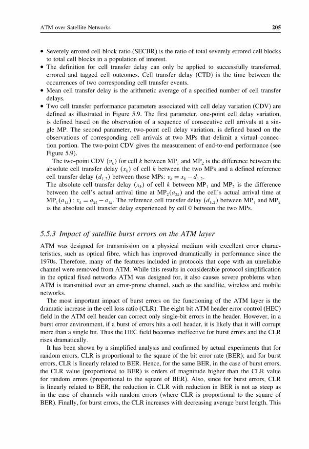
ATM over Satellite Networks 205
• Severely errored cell block ratio (SECBR) is the ratio of total severely errored cell blocksto total cell blocks in a population of interest.
• The definition for cell transfer delay can only be applied to successfully transferred,errored and tagged cell outcomes. Cell transfer delay (CTD) is the time between theoccurrences of two corresponding cell transfer events.
• Mean cell transfer delay is the arithmetic average of a specified number of cell transferdelays.
• Two cell transfer performance parameters associated with cell delay variation (CDV) aredefined as illustrated in Figure 5.9. The first parameter, one-point cell delay variation,is defined based on the observation of a sequence of consecutive cell arrivals at a sin-gle MP. The second parameter, two-point cell delay variation, is defined based on theobservations of corresponding cell arrivals at two MPs that delimit a virtual connec-tion portion. The two-point CDV gives the measurement of end-to-end performance (seeFigure 5.9).The two-point CDV vk for cell k between MP1 and MP2 is the difference between the
absolute cell transfer delay xk of cell k between the two MPs and a defined referencecell transfer delay d12 between those MPs: vk = xk−d12.The absolute cell transfer delay xk of cell k between MP1 and MP2 is the differencebetween the cell’s actual arrival time at MP2a2k and the cell’s actual arrival time atMP1a1k xk = a2k−a1k. The reference cell transfer delay d12 between MP1 and MP2
is the absolute cell transfer delay experienced by cell 0 between the two MPs.
5.5.3 Impact of satellite burst errors on the ATM layer
ATM was designed for transmission on a physical medium with excellent error charac-teristics, such as optical fibre, which has improved dramatically in performance since the1970s. Therefore, many of the features included in protocols that cope with an unreliablechannel were removed from ATM. While this results in considerable protocol simplificationin the optical fixed networks ATM was designed for, it also causes severe problems whenATM is transmitted over an error-prone channel, such as the satellite, wireless and mobilenetworks.The most important impact of burst errors on the functioning of the ATM layer is the
dramatic increase in the cell loss ratio (CLR). The eight-bit ATM header error control (HEC)field in the ATM cell header can correct only single-bit errors in the header. However, in aburst error environment, if a burst of errors hits a cell header, it is likely that it will corruptmore than a single bit. Thus the HEC field becomes ineffective for burst errors and the CLRrises dramatically.It has been shown by a simplified analysis and confirmed by actual experiments that for
random errors, CLR is proportional to the square of the bit error rate (BER); and for bursterrors, CLR is linearly related to BER. Hence, for the same BER, in the case of burst errors,the CLR value (proportional to BER) is orders of magnitude higher than the CLR valuefor random errors (proportional to the square of BER). Also, since for burst errors, CLRis linearly related to BER, the reduction in CLR with reduction in BER is not as steep asin the case of channels with random errors (where CLR is proportional to the square ofBER). Finally, for burst errors, the CLR increases with decreasing average burst length. This

206 Satellite Networking: Principles and Protocols
T1316580-99
Cell 0
Cell 0Cell 0
Cell 1
Cell 2
Cell k
Cell 1
Cell 2
Cell k
Cell 1
Cell 2
Cell 4
Cell 5
Cell k
Cell 3
MP
t = 0
t = 0
T
T
T
T
T
T
Clockstop
c1a1
a2
a3
a4
a5
ak
c2
c3
c4
c5
ck
ReferenceClock
Variables:
ak Cell k actual arrival time at MP
ck Cell k reference arrival time at MP
yk 1-point CDV
Variables:
a1,k Cell k actual arrival time at MP1
a2,k Cell k actual arrival time at MP2
d1,2 Absolute cell 0 transfer delay between MP1 and MP2
xk Absolute cell k transfer time between MP1 and MP2
vk 2-point CDV value between MP1 and MP2
yk = ck – ak
xk = a2,k – a1,k
vk = xk – d1,2
a) Cell delay variation – 1-point definition
MP2MP1
b) Cell delay variation – 2-point definition
d1,2
a1,1
a1,2
a1,k
a2,1
a2,2
a2,k
d1,2 vk
xk
Figure 5.9 Cell delay variation parameter definitions (ITUT-1356) (Reproduced with the kind per-mission of ITU.)

ATM over Satellite Networks 207
is because for the same number of total bit errors, shorter error bursts mean that a largernumber of cells are affected.Another negligible but interesting problem is that of misinserted cells. Since eight HEC
bits in the ATM cell header are determined by 32 other bits in the header, there are only232 valid ATM header patterns out of 240 possibilities (for 40ATM header bits). Thus fora cell header, hit by a burst of errors, there is a 232/240 chance that corrupted header is avalid one. Moreover, if the corrupted header differs from a valid header by only a single bit,HEC will ‘correct’ that bit and accept the header as a valid one. Thus for every valid headerbit pattern (out of 232 possibilities), there are 40 other patterns (obtained by inverting onebit out of 40) that can be ‘corrected’. The possibility that the ‘error burst’ hit the header inone of these patterns is 40×232/240. Thus overall, there is a 41×232/240= 41/256≈ 1/6chance that a random bit pattern, emerging after an ATM cell header is hit by a burst oferrors, will be taken as a valid header. In that case a cell, that should have been discarded, isaccepted as a valid cell. (Errors in the payload must be detected by the transport protocol atthe end points.) Such a cell is called a ‘misinserted’ cell. Also, the probability Pmi that a cellwill be misinserted in a channel with burst errors is around 1/6th of the cell loss ratio on thechannel, i.e.,
Pmi ≈ 1/6×CLR
Since CLR can be written as a constant times BER, the misinserted cell probability is alsoa constant times BER, i.e.,
Pmi = k×BER
The cell insertion rate, Cir, the rate at which cells are inserted in a connection, is obtainedby multiplying this probability by the number of ATM cells transmitted per second (r),divided by total possible number of ATM connections 224, i.e.,
Cir = k×BER× r /224
Because of the very large number of total possible ATM connections, the cell insertionrate is negligible (about one inserted cell per month) even for high BER ≈ 10−4 and datarates ≈ 34Mbit/s. Therefore, transition from random errors to burst errors causes the ATMCLR metric to rise significantly.
5.5.4 Impact of burst errors on AAL protocols
The cyclic error detection codes employed by AAL protocols type 1, 3/4 and 5 are susceptibleto error bursts in the same way as the ATM HEC code. A burst of errors that passesundetected through these codes may cause failure of the protocol’s mechanism or corruptionin data. AAL type 1’s segmentation and reassembly (SAR) header consists of four bits ofsequence number (SN) protected by a three-bit CRC code and a single-bit parity check.

208 Satellite Networking: Principles and Protocols
There is a 15/255 = 1/17 chance that an error burst on the header will not be detected bythe CRC code and parity check. Such an undetected error at the SAR layer may lead tosynchronisation failure at the receiver’s convergence sublayer. AAL 3/4 uses a 10-bit CRCat the SAR level.Here, burst errors and scrambling on the satellite channel increase the probability of
undetected error. However, full byte interleaving of the ATM cell payload can reduceundetected error rate by several orders of magnitude by distributing the burst error into twoAAL 3/4 payloads. The price to be paid for distributing burst error into two AAL payloadsis doubling of the detected error rate and AAL 3/4 payload discard rate. AAL type 5 uses a32-bit CRC code that detects all burst errors of length 32 or less. For longer bursts, the errordetection capability of this code is much stronger than that of AAL 3/4 CRC. Moreover, ituses a length check field, which finds out loss or gain of cells in an AAL 5 payload, evenwhen CRC code fails to detect it. Hence it is unlikely that a burst error in AAL 5 payloadwould go undetected.It can be seen that ATM AAL 1 and 3/4 are susceptible to burst errors, as there are less
redundant bits used for protections. AAL 5 is more robust against burst errors by using moreredundant bits.
5.5.5 Error control mechanisms
There are three types of error control mechanisms: re-transmission mechanism, forwarderror control (FEC) and interleaving techniques to improve quality for ATM traffic oversatellite.Satellite ATM networks try to maintain BER below 10−8 in clear sky operation 99% of
the time. The burst error characteristics of FEC-coded satellite channels adversely affect theperformance of physical, ATM and AAL protocols. The interleaving mechanism reduces theburst error effect of the satellite links.A typical example of FEC is to use an outer Reed–Solomon (RS) coding/decoding in
concatenation with ‘inner’ convolutional coding/Viterbi decoding. Outer RS coding/decodingwill perform the function of correcting error bursts resulting from inner coding/decoding.RS codes consume little extra bandwidth (e.g. 9% at 2Mbit/s).HEC codes used in ATM and AAL layer headers are able to correct single bit errors in
the header. Thus, if the bits of N headers are interleaved before encoding and de-interleavedafter decoding, the burst of errors will get spread over N headers such that two consecutiveheaders emerging after de-interleaving will most probably never have more than a singlebit in error. Now the HEC code will be able to correct single bit errors and by dual modeof operation, no cell/AAL PDU will be discarded. Interleaving involves reshuffling of bitson the channel and there is no overhead involved. However, the process of interleavingand de-interleaving requires additional memory and introduces delay at both sender andreceiver.Burst errors can be mitigated by using FEC and ‘interleaving’ techniques. The performance
of these schemes is directly related to the code rate (bandwidth efficiency) and/or the codinggains (power efficiency), provided the delay involved is acceptable to any ATM-basedapplication.

ATM over Satellite Networks 209
5.5.6 Enhancement techniques for satellite ATM networks
In satellite ATM networks, we have to exploit the FEC coding and interleaving, and tradeoff between transmission quality in terms of bit error performance and satellite resourcessuch as bandwidth and power:
• ATM was designed for transmission on a physical medium with excellent error charac-teristics, such as optical fibre. It has less overhead, by reducing error controls, but it alsocauses severe problems when ATM is transmitted over an error-prone channel, such asthe satellite link.
• Satellite systems are usually power or bandwidth limited and in order to achieve reliabletransmission FEC codes are often used in satellite modems. With such codes (typicallyconvolutional codes), the incoming data stream is no longer reconstructed on a symbol-by-symbol basis. Rather some redundancy in the data stream is used.
• On average, coding reduces the BER or alternatively decreases transmission powerneeded to achieve a certain QoS for a given S/N ratio, at the expense of coding over-head. However, when decoding makes mistakes, in general a large number of bitsis affected, resulting in burst errors. Because ATM was designed to be robust withrespect to random single bit errors, burst errors can degrade the performance of ATMconsiderably.
Hence some enhancement techniques can be developed to make the transmission of ATMcells over the satellite link more robust. The performance of these techniques is directlyrelated to the code rate (bandwidth efficiency) and/or the coding gain (power efficiency),provided the processing delay involved is acceptable to any ATM-based application.For large earth stations operating at high data rates, the enhancement techniques try to
deal with burst errors.
• By interleaving the ATM cell headers (not the payload) of several cells the performanceof ATM in a random single bit error channel (e.g. AWGN channel) can be achieved. Notethat interleaving merely reshuffles the bits on the channel (to spread the bit errors amongATM cell headers) and does not produce additional overhead which might decrease theoverall bit rate. However, interleaving requires memory at the transmitter and the receiver,and it introduces additional delay. Assuming an average number of 30 bit errors in anerror burst, interleaving over 100 cell headers seems to be sufficient. This requires amemory of only about 10 kbytes and introduces a delay of 840s at 50Mbit/s and adelay of 21ms at 2Mbit/s. Since the above interleaving scheme requires a continuous datastream, there are problems using it for portable terminals where single ATM cells may betransmitted.
• Another way of correcting the burst errors due to FEC techniques applied to satellite linksare Reed–Solomon (RS) codes. This type of block codes, which are based on symbols,have been identified as performing particularly well in concatenation with convolutionalFEC codes, because of their ability to correct bursts of errors.
• Moreover, error bursts longer than what the RS code can correct should be spread overseveral blocks to take advantage of the error correction capabilities of the block code.This can be done by interleaving between the two codes.

210 Satellite Networking: Principles and Protocols
For broadband small and portable terminals, rapid deployment and relocation are importantrequirements. The transmission bit rates can be up to but normally below 2.048Mbit/s.Since inter-cell interleaving is not feasible because only a few cells may be transmittedfrom the terminal, mechanisms which protect single cells have to be found. Interleavingwithin an entire ATM cell (not only the header), so-called intra-cell interleaving, leads to aperformance gain which is too small to be effective.It can be improved by using additional coding to protect the ATM cells. Note that this
introduces additional overheads and therefore reduces the useful data bit rate. There areseveral reasons why FEC or concatenated FEC may not be suitable for enhancing ATMperformance over wideband satellite links. First, if only FEC coding is used, than symbolinterleaving is usually used to spread the burst errors over several ATM cell headers. Theresulting interleaving delay (which is inversely proportional to the data rate) may be toolarge at a low rate for certain applications. Second if RS codes are used to correct burst oferrors in concatenation with FEC either additional bandwidth has to be provided or the datarate has to be reduced.It is also possible to improve ATM performance by enhancing equipment which optimises
the ATM protocols over a satellite link. This allows the data link layer to be optimisedusing a combination of protocol conversions and error control techniques. At the transmitter,standard ATM cells are modified to suit the satellite link. At the receiver, error recoverytechniques are performed and the modified ATM cells (S-ATM cells) are converted intostandard ATM cells.The main aim of modifying standard ATM cell is to minimise the rather large ATM
header overhead which is 5 bytes per 48 byte payload. Of the ATM header information, theaddress field (which is divided into the VPI and VCI) occupies 24 bits. This allows up to16 million VC to be set up. Considering that in particular CBR connection cells all carrythe same address information in the header, there may be methods not to duplicate the sameinformation. The use of 24 bits for address space may be considered a waste of bandwidthfor this scenario.One method to protect the ATM cell header is, when interleaving is not possible, to
compress the 24 bits address space to eight bits so that the saved bits can be used to storethe duplicate header information (except the HEC field) of the previous cell. The HEC isstill computed over the first four bytes of the header and inserted into the fifth byte ofthe header. Therefore if a cell header contains errors, the receiver can store the payloadin a buffer and recover the header information from the next cell provided that its headerdoes not also contain errors. This method does not intend to protect payload. Studies showthat this method provides considerable improvements in CLR compared to standard ATMtransmission and even compared to interleaving.Another alternative is to use three-byte HEC instead of one-byte HEC, which is inadequate
for the satellite environment.
5.6 Evolution of ATM satellite systems
While fibre optics is rapidly becoming the preferred carrier for high bandwidth communica-tion services, satellite systems can still play an important role in the B-ISDN. The satellitenetwork configuration and capacity can be increased gradually to match the increasingB-ISDN traffic during the evolution toward broadband communications.

ATM over Satellite Networks 211
The role of satellites in high-speed networking will evolve according to the evolutionof the terrestrial ATM based networks. However, two main roles can be identified in twoscenarios of the broadband network development:
• The initial phase when satellites will compensate the lack of sufficient terrestrial highbit rate links mainly by interconnecting a few regional or national distributed broadbandnetworks, usually called ‘broadband islands’.
• The maturation phase when the terrestrial broadband infrastructure will have reachedsome degree of maturity. In this phase, satellites are expected to provide broadcast serviceand also cost-effective links to rural areas complementing the terrestrial network. At thisphase satellite networks will provide broadband links to a large number of end usersthrough a UNI for accessing broadband networks. This allows high flexibility concerningtopology, reconfiguration and network expansion. Satellites are also ideal for intercon-necting mobile sites and provide a back-up solution in case of failure of the terrestrialsystems.
In the first scenario, satellite links provide high bit rate links between broadband nodesor broadband islands. The CATALYST demonstrator provided an example for this scenarioand considerations for compatibility between satellite and terrestrial networks. The interfaceswith satellite links in this mode are of the NNI type. This scenario is characterised by arelatively small number of large earth stations, which have a relatively large average bitrate.In the second scenario the satellite can also be located at the border of broadband networks
to provide access links to a large number of users. This scenario is characterised by a largenumber of earth stations whose average and peak bit rates are limited. The traffic at the earthstation is expected to show large fluctuations. Dynamic bandwidth allocation mechanismsare used for flexible multiple access.The problem for efficient use of satellite resources is due to the unpredictable nature
of burst traffic and the long delay of the satellite link to reallocate and manage satelliteresources. More research has to be carried out on efficient multiple access schemes forsatellite systems. The use of OBP satellites with cell-switching capabilities and spot beamswould half this delay and bring several advantages for interconnecting a high number ofusers. By using on-board cell switching the utilisation of the satellite bandwidth can bemaximised by statistically multiplexing the traffic in the sky.The use of GEO satellites to deliver ATM services has proven feasible. However, delivery
of high bit rate ATM services to transportable or mobile terminals via satellite requireslow delays, low terminal power requirements and high minimum elevation angles. It is anatural evolution path to exploit satellites at much lower altitudes such as MEO and LEOorbit heights. Satellites at these lower altitudes have much smaller delays and lower terminalpower requirements than satellites in GEO orbit. Research is still going on to find the mostsuitable orbit and multiple access schemes to deliver broadband services to small portableand mobile terminals.The major factor affecting the direction of satellite broadband networking comes from
terrestrial networks where networks are evolving towards all-IP solutions. Therefore, it is alogical step to investigate IP routers on board satellites.

212 Satellite Networking: Principles and Protocols
Further reading[1] ITU-T Recommendation I.150, B-ISDN ATM Functional Characteristics, November 1995.[2] ITU-T Recommendation I.211, B-ISDN Service Aspects, March 1993.[3] ITU-T Recommendation I.356, On B-ISDN ATM Layer Cell Transfer Performance, October 1996.[4] ITU-T Recommendation I.361, ITU-T ‘B-ISDN ATM Layer Specification, November 1995.[5] ITU-T Recommendation I.371, Traffic Control and Congestion Control in B-ISDN, May 1996.[6] ITU-T Recommendation G826, ‘Error performance parameters and objectives for international constant bit
rate digital paths at or above the primary rate’, 02/1999.[7] Ors, T., ‘Traffic and congestion control for ATM over satellite to provide QoS’, PhD thesis, University of
Surrey, 1998.[8] RACE CFS, Satellites in the B-ISDN, general aspects, RACE Common Functional Specifications D751, Issue
D, December 1993.[9] Sun, Z., T. Ors and B.G. Evans, Satellite ATM for broadband ISDN, Telecommunication Systems, 4:119–31,
1995.[10] Sun, Z., T. Ors and B.G. Evans, ATM-over-satellite demonstration of broadband network interconnection,
Computer Communications, Special Issue on Transport Protocols for High Speed Broadband Networks,21(12), 1998.
Exercises
1. Explain the design issues and concepts concerning ATM over satellites.2. Explain the CATALYST GEO satellite ATM networking and advanced satellite
networking with LEO/MEO constellations.3. Use a sketch to explain the major roles of satellites in broadband networks with
ATM over satellite networking and also the protocol stacks of the broadbandnetwork interconnection and terminal access configurations.
4. Explain the differences between satellites with transparent and on-board switchingpayload for ATM networks, and discuss advantages and disadvantages.
5. Explain ATM performance issues and enhancement techniques for satellite ATMnetworks.
6. Explain different on-board processing and on-board switching techniques, and dis-cuss their advantages and disadvantages.
7. Discuss the advantages and disadvantages of ATM networks based on GEO, MEOand LEO satellites.

6Internet Protocol (IP) over SatelliteNetworks
This chapter aims to provide an introduction to the Internet protocol (IP) over satellitenetworks. It explains satellite networking from different viewpoints: protocol centric, networkcentric and satellite centric. It also explains: how to encapsulate IP packet into differentframes of different network technologies; IP extensions including IP multicast, IP securityand IP QoS; the concepts of DVB over satellite (DVB-S and DVB-RCS); and IP QoSarchitectures. When you have completed this chapter, you should be able to:
• Understand the concepts of satellite IP networking.• Understand IP packet encapsulation concepts.• Describe different views of satellite networks.• Describe IP multicast over satellite.• Explain DVB and related protocol stack.• Explain DVB over satellite including DVB-S and DVB-RCS.• Explain IP over DVB-S and DVB-RCS security mechanisms.• Knows IP QoS performance objectives and parameters and QoS architectures of Intservand Diffserv.
6.1 Different viewpoints of satellite networking
Like terrestrial networks, satellite networks are increasingly carrying more and more Inter-net traffic, which now exceeds telephony traffic. Currently, Internet traffic is mainly dueto classical Internet services and applications, such as WWW, FTP and emails. Satellitenetworks only need to support the classical Internet network applications in order to providetraditional best-effort services.
Satellite Networking: Principles and Protocols Zhili Sun© 2005 John Wiley & Sons, Ltd

214 Satellite Networking: Principles and Protocols
The convergence of the Internet and telecommunications led to the development of voiceover IP (VoIP), video conference over IP and broadcasting services over IP. Therefore, IPpackets are expected to carry additional classes of services and applications over satellitenetworks, requiring quality of service (QoS) from IP networks. Much research and develop-ment have been carried out in satellite networking to support the new real-time multimediaand multicast applications requiring QoS.IP has been designed to be independent of any network technology so that it can be
adapted to all available networking technologies. For satellite networks, there are three ofthe satellite networking technologies concerning IP over satellites:
• Satellite telecommunication networks – these have provided traditional satellite services(telephony, fax, data, etc.) for many years, and also provide Internet access and Internetsubnet interconnections by using point-to-point links.
• Satellite shared medium packet networks based on the very small aperture terminal (VSAT)concept – these have supported transaction types of data services for many years, and arealso suitable for supporting IP.
• Digital video broadcasting (DVB) – IP over DVB via satellite has the potential to providebroadband access for global coverage. DVB-S provides one-way broadcasting services.User terminals can only receive data via satellite. For Internet services, the return linksare provided using dial-up links over telecommunication networks. DVB-RCS providesreturn links via satellite so that user terminals can access the Internet via satellite. Thisremoves all constraints due to return links over terrestrial telecommunications networks,hence allowing great flexibility and mobility for the user terminals.
6.1.1 Protocol-centric viewpoint of satellite IP network
The protocol-centric viewpoint of satellite IP networks emphasises the protocol stack andprotocol functions in the context of the reference model. Figure 6.1 illustrates the relationshipbetween IP and different network technologies. IP provides a uniform network hiding awayall differences between different technologies; different networks may transport IP packetsin different ways.
TCP/UDP
Applications
Internet Protocol (IP)
NetworkInterface,
Diver,Controller
NetworkInterface,
Diver,Controller
NetworkInterface,
Diver,Controller
TCP/UDP
Applications
Host Host
Router
Terrestrialnetworks
Internet
On Board Router
Satellitenetworks
Figure 6.1 Relationship between IP and different network technologies

Internet Protocol (IP) over Satellite Networks 215
Satellite networks include connection-oriented networks, shared medium point-to-multipoint connectionless networks, broadcasting networks for point-to-point communica-tions and point-to-multipoint communications. Terrestrial networks include LAN, MAN,WAN, dial-up, circuit networks and packet networks. LAN is often based on a sharedmedium and WAN point-to-point connections.
6.1.2 Satellite-centric viewpoint of global networks and the Internet
The satellite-centric viewpoint emphasises the satellite network itself, i.e. the satellite (GEOor non-GEO) is viewed as a fixed infrastructure and all ground infrastructures are viewed inrelation to the satellite. Figure 6.2 illustrates a satellite-centric viewpoint of global networks.Figure 6.3 shows mapping from the earth-centric viewpoint to a GEO satellite-centric view-
point of earth and LEO satellites (
OG = OOG is vector from O to OG the location of theGEO satellite, and
∣∣∣r ∣∣∣= RG is the GEO orbit with radius of RG) that the earth surface andsatellite orbits can be expressed as:
2 =(r −
OG
)2
2RG
−1
RG−RE
where RE is the radius of earth, and
2 =(r −
OG
)2
2RG
−1
RG−RL
where RL is the radius of the LEO satellite orbit.
Coverage
Internet
Host
LAN
Accesspoint
PublicNetwork Uplink
DownlinkBroadcasting
HubTransmitter Receiver only
terminals
Satellite network
Bi-directional
Earth surface
Figure 6.2 Satellite-centric viewpoint of global networks

216 Satellite Networking: Principles and Protocols
Orbit of LEOsatellite
constellation
LEOsatellite
r = RL
r = RE
Earthstation
O
Earth
RE
OG
RL
RG
E S
LEO satellitein GEO satellitecentric of view
Earth surfacein GEO satellitecentric of view
GEOsatellite
2RG
y2 =r – OG( (
–1
2
(RG –
RE)
2RG
γ 2 =
r –
OG( (
–1
2
(RG –
RL)
Figure 6.3 Mapping from earth-centric view to GEO-centric view
To support IP, the satellite network must support data frames to carry IP packets acrossthe network technology. The router takes the IP packet from frames of one type of networkand repackages the IP packet into frames of another type of network to make them suitablefor transmission in the network technologies.
6.1.3 Network-centric viewpoint of satellite networks
Satellite systems and technologies concern two aspects: the ground segment and the spacesegment. In the space segment (satellite communication payload), various types of technol-ogy can be used including transparent (bent-pipe) transponder, on-board processor, on-boardcircuit switch, on-board packet switch (also possible ATM switch), on-board DVB-S orDVB-RCS switch or IP router. The network-centric view of satellite networks emphasisesnetworking functions rather than satellite technologies. However, users see different typesof networks and logical connections rather than satellite technologies and physical imple-mentations. Figure 6.4 shows a network-centric view of satellite networks.
Satellite TelecomNetwork
Satellite ATMNetwork
DVB-S andDVB-RCSTerminal Terminal Terminal
Figure 6.4 Network-centric view of satellite networks

Internet Protocol (IP) over Satellite Networks 217
All these additional functions increase the complexity of the satellite payload capable ofsupporting multiple spot-beam ‘star’ (point-to-multipoint centred on a gateway earth station)and ‘mesh’ (multipoint-to-multipoint) topologies, hence the risk of failure, but they alsoprovide great benefit of optimised use of bandwidth and power resources. Future satelliteswith on-board DVB switching will be able to integrate broadcast and interactive services bycombining DVB-S and DVB-RCS standards. A DVB-S regenerative payload can multiplexinformation from diverse sources into a standard downlink DVB-S stream. Another exampleof the use of DVB on-board switching is to interconnect LANs using IP over MPEG-2encapsulation, via a regenerative satellite payload.Implementation of these functions depend on the demands of network operators and secure
manufacturing to produce reliable and cost-effective satellites.
6.2 IP packet encapsulation
IP packet encapsulation is an aspect for IP over any network technology. It is a technique usedto encapsulate an IP packet into the data frame, so that it is suitable for transmission overthe network technology. Different network technologies may also use different frame formats,frame sizes or bit rate for transporting IP packets. IP packet encapsulation puts the packet intothe payload of a data link layer frame for transmission over the network. For example, Ethernet,token ring and wireless LANs have their own standard frame formats to encapsulate IP packet.
6.2.1 Basic concepts
Due to different framing formats, different encapsulation techniques may be used. Some-times, an IP packet may be too large to fit into the frame payload. In such a case, the IPpacket has to be broken up into smaller segments (fragmented) so that the IP packet canbe carried over several frames. In this case, additional overhead is added to each of thesegments so that on arriving at the destination, the original IP packet can be reassembledfrom the segments. It can be seen that the encapsulation process may have a significantimpact on network performance due to the additional processing and overhead. Figure 6.5illustrates the concept of encapsulation of IP packets.
6.2.2 High-level data link control (HDLC) protocol
HDLC is an international standard of layer 2 (link layer) protocols. It is an important andalso widely used layer 2 protocol. It defines three types of stations (standard, secondary and
FLAG Header Payload Trailer FLAG
IP packet IP packet is the same inthe Internet globally
Packaged intoformat suitable forthe transmissionnetwork
Figure 6.5 Basic concept of encapsulation of an IP packet

218 Satellite Networking: Principles and Protocols
Flag01111110
Address Control Payload ChecksumFlag
01111110
1 3 1 3
1
1 0
1 1
Type
Sequence
Type
P/F
P/F
P/F Next
Next
Modifier
Bits
Bits
(a) Information frame
(b) Supervisory frame
(c) Unnumbered frame
8 8 8 > = 0 16 8
Figure 6.6 HDLC frame structure
combined), two link configurations (balanced and unbalanced) and three data transfer modes(normal response, asynchronous response, asynchronous balanced response). Figure 6.6shows the HDLC frame structure.It is bit oriented based on a bit-stuffing technique, and consists of two flags of the eight-bit
pattern 01111110 to identify the start and end of the frame, an eight-bit address field toidentify multiple terminals, an eight-bit control field to be used for three types of frames(information, supervision and unnumbered), a payload field to carry data (network layer dataincluding IP packet) and 16 bits for CRC error check.
6.2.3 Point-to-point protocol (PPP)
The HDLC frame is adapted for the point-to-Point protocol (PPP), which is the Internetstandard widely used for dial-up connections. The PPP handles error detection, supportsmultiple protocols in addition to IP, allows addresses be negotiated at connection time andpermits authentication. Figure 6.7 shows the frame structure of the PPP.
Default is 1500.Default is 2.
0: Net layer protocol1: otherDefault
Default forUnnumberedframe
Flag01111110
Address11111111
Control00000011
Bytes
Protocol Payload ChecksumFlag
01111110
Normally 2 butcan be negotiatedfor 4
1 1 1 1 or 2 Variable 2 or 4 1
Figure 6.7 Frame structure of the point-to-point protocol (PPP)

Internet Protocol (IP) over Satellite Networks 219
6.2.4 Media access control
HDLC and PPP were designed for transmission over point-to-point connection media. Fora network of shared media, an additional layer, known as the media access control (MAC)sublayer of the link layer, is used to connect a large number of stations into the network.Without giving full details, Figure 6.8 illustrates a format of MAC frame.
6.2.5 IP over satellite
To support IP over satellites, the satellite networks need to provide a frame structure so thatthe IP datagram can be encapsulated into the frame and transported via satellite from oneaccess point to other access points. In a satellite environment, the frame can be based onstandard data link layer protocols. Encapsulation of IP is also defined in the existing networks,such as dial-up link, ATM, DVB-S and DVB-RCS, which support Internet protocols orinterwork with the Internet. ATM networks use ATM adaptation layer type 5 (AAL5) toencapsulate IP packets for transmission over the ATM network, and in DVB-S, IP packetsincluding multicast are encapsulated in an Ethernet-style header using a standard calledmulti-protocol encapsulation (MPE).It is also possible to encapsulate an IP packet into another IP packet, i.e., to create a tunnel
to transport the IP packets of one Internet across another Internet network.
6.3 Satellite IP networking
The particular benefits provided by satellites include their geographically extended globalcoverage (including land, sea and air), their efficient delivery to a large number of userson a large scale, and the low marginal cost of adding additional users. A satellite can playseveral different roles in the Internet:
• Last mile connections (as shown in Figure 6.9): user terminals directly access the satellite,which provides direct forward and return links. Traffic sources connect to the satellitefeeder or hub stations through the Internet, tunnelling or dial-up links. It is the last mileto reach user terminals.
• Transit connections (as shown in Figure 6.11): the satellite provides connections betweenInternet gateways or ISP gateways. The traffic is routed through the satellite links accordingto specified routing protocols and defined link metrics in the networks so as to minimiseconnection costs and to meet required QoS constraints for the given traffic sources.
• First mile connections (as shown in Figure 6.10): the satellite provides forward and returnlink connections directly to a large number of ISPs. IP packets start from the servers as thefirst mile of their journey to user terminals. As with the last mile connections, the server
MACcontrol
DestinationMAC address
SourcesMAC address
Payload for encapsulatedIP packet
Checksum
Figure 6.8 Format of a MAC frame

220 Satellite Networking: Principles and Protocols
Coverage
Internet
Host Accesspoint
Gatewayearthstation
Satellite network
Earth surface
Userearthstation
Figure 6.9 Satellite-centric view of last mile connections to the Internet
Coverage
ISP 1
Servers
Gatewayearthstation
Satellite network
Earth surfaceUserearthstation
ISP 2
ISP 3
ISP 4
Terminals
Figure 6.10 Satellite-centric view of first mile connections to the Internet
Coverage
ISP 1
Gatewayearthstation
Satellite network
Earth surfaceGatewayearthstation
ISP 2
ISP 3
ISP 4
ISP 5
ISP 6
Figure 6.11 Satellite-centric view of transit connections to the Internet

Internet Protocol (IP) over Satellite Networks 221
can connect to the satellite feeder or hub stations directly or through the Internet tunnellingor dial-up links.
6.3.1 Routing on board satellites
The benefit of an IP router in the sky is that it allows satellite networks to be integratedinto the global Internet using the standard routing algorithms. The Internet consists of acollection of subnetworks, also known as autonomous systems (AS) or domains.In GEO satellite networks, there is normally only one satellite covering a large area to
form a subnet; there is no routing within the satellite network. With a constellation, there aremany satellites forming a subnet to cover the earth. Therefore, routing within the constel-lation satellite network is required. The link relationships between the satellites within thesame orbit plane are fixed, but change dynamically in different planes. Since the locationsof all the satellites in the orbits are predictable, it is possible to make use of the predic-tions to dynamically update the routing tables on board satellites and enhance the routingalgorithm.
6.3.2 IP mobility in satellite networks
Due to the wide coverage of GEO satellites, we can consider that terrestrial networks areconnected to the same satellite subnet permanently, and to user terminals during com-munication sessions. However, for a network with a constellation of LEO satellites therelationships between the satellite network and user terminals and terrestrial networks arechanging continuously. Therefore, there are several issues concerned with mobility:
• Re-establishing the physical connections with the satellite networks.• Timely updating the routing table so that IP packets can be routed to the right destination.• Mobility within the satellite networks.• Mobility between terrestrial networks and satellite networks.
Here, discussions are based on the Internet standard protocol for mobile IP (RFC 2002).In the standard solution, it allows the mobile node to use two IP addresses: a fixed homeaddress and a care-of address, which changes at each new point of attachment. We take thesatellite-centric view that the satellite network is fixed but everything on the earth is movingincluding user terminals and the terrestrial network as shown in Figure 6.12.In the IP mobility standard, existing transport layer connections are maintained as the
mobile node moves from one place to another; IP addresses remain the same. Most ofthe Internet applications used today are based on TCP. A TCP connection is indexed bya quadruplet of source IP addresses, destination IP addresses, source port number anddestination port number. Changing any of these four numbers will cause the connection tobe disrupted and lost. On the other hand, correct delivery of packets to the mobile node’scurrent point of attachment depends on the network number contained within the mobilenode’s IP address, which changes at new points of attachment.In mobile IP, the home address is static and is used, for instance, to identify TCP
connections. The care-of address changes at each new point of attachment and can be thought

222 Satellite Networking: Principles and Protocols
Relating to the satellitenetwork, everything in
the earth is moving
Consider thesatellite network is
fixed
Network
Figure 6.12 Satellite-centric view of fixed satellites with earth moving
of as the mobile node’s topologically significant address; it indicates the network number andthus identifies the mobile node’s point of attachment with respect to the network topology.The home address makes it appear that the mobile node is continually able to receive dataon its home network, where mobile IP requires the existence of a network node known asthe home agent. Whenever the mobile node is not attached to its home network (and istherefore attached to what is termed a foreign network), the home agent gets all the packetsdestined for the mobile node and arranges to deliver them to the mobile node’s current pointof attachment.When the mobile node moves to a new place, it registers its new care-of address with
its home agent. To get a packet to a mobile node from its home network, the home agentdelivers the packet from the home network to the care-of address. The further deliveryrequires to the care-of address to transform or redirect the IP packet. When the packet arrivesat the care-of address, the reverse transformation is applied so that the packet once againappears to have the mobile node’s home address as the destination IP address.When the packet arrives at the mobile node, addressed to the home address, it will be
processed properly by TCP.In mobile IP the home agent redirects packets from the home network to the care-of
address by constructing a new IP header that contains the mobile node’s care-of address asthe destination IP address. This new header then shields or encapsulates the original packet,causing the mobile node’s home address to have no effect on the encapsulated packet’srouting until it arrives at the care-of address. Such encapsulation is also called tunnelling,which bypasses the usual effects of IP routing.Mobile IP, then, is best understood as the cooperation of three separate mechanisms:
• Discovering the care-of address: agent advertisement and agent solicitation (RFC1256).• Registering the care-of address: the registration process begins when the mobile nodeenters coverage of a foreign agent, sends a registration request with the care-of address

Internet Protocol (IP) over Satellite Networks 223
information. When the home agent receives this request, it (typically) adds the necessaryinformation to its routing table, approves the request, and sends a registration reply back tothe mobile node. The registration is authenticated by using Message Digest 5 (RFC1321).
• Tunnelling to the care-of address: the default encapsulation mechanism that must besupported by all mobility agents is IP-within-IP (tunnelling). Minimal encapsulation isslightly more complicated than tunnelling, because some of the information from thetunnel header is combined with the information in the inner minimal encapsulation headerto reconstitute the original IP header. On the other hand, header overhead is reduced.
6.3.3 Address resolution
Address resolution is also called address mapping and configuration. Different networktechnologies may use different addressing schemes for assigning addresses, also calledphysical addresses, to devices. For example, an IEEE 802 LAN uses a 48-bit address foreach attached device, an ATM network may use 15-digit decimal address and ISDN usesthe ITU-T E.164 address scheme. Similarly, in a satellite network each ground earth stationor gateway station has a physical address for circuit connections or packet transmissions.However, the routers that are interconnected by the satellite network know only the IPaddresses of the other routers. Therefore, address mapping between each IP address and itsrelated physical address is required, so that packet exchanges between the routers can becarried out through the satellite network using the physical addresses. The precise details ofthis mapping depend on the underlying data link layer protocols used over the satellite.
6.4 IP multicast over satellite
The success of satellite digital broadcast services (for TV and radio) and the asymmetricnature of IP traffic flow have been combined resulting in satellite systems that support high-speed Internet access. From here, it is a natural step to consider further exploiting satellites’broadcast capability by investigating IP multicast over satellites. Satellite networks can bepart of an IP multicast routing tree at the source, trunk or end branch forwarding IP packetstowards their destination. Figure 6.13 illustrates an example of star and mesh topologiesused in the GEOCAST project on IP multicast over GEO satellite funded within the EU 5thframework programme.
6.4.1 IP multicast
We now proceed to review IP multicast technology. Multicast allows a communicationsnetwork source to send data to multiple destinations simultaneously while transmitting onlya single copy of the data to the network. The network then replicates the data and fans it outto recipients as necessary. Multicast can be considered as part of a spectrum of three typesof communications:
• Unicast: transmitting data from a single source to a single destination (for example,downloading a web page from a server to a user’s browser, or copying a file from oneserver to another).

224 Satellite Networking: Principles and Protocols
UESGES
UES
UES
R
RInternet
Corporate
Consumer
Prosumer
GES: Gateway Earth StationUES: User Earth Station
Star multicast Mesh multicast
Gateway
Figure 6.13 The GEOCAST system as an example of star and mesh topologies
• Multicast: transmitting data from a single source to multiple destinations. The defi-nition also encompasses communications where there may be more than one source(i.e. multipoint-to-multipoint). Videoconferences provide an example of the latter, whereeach participant can be regarded as a single source multicasting to the other participantsin the videoconference.
• Broadcast: transmitting data from a single source to all receivers within a domain(e.g. within a LAN, or from a satellite to all receivers within a satellite spot beam).
The advantages of multicast are as follows:
• Reduced network bandwidth usage: for example, if data packets are being multicast to100 recipients the source only sends a single copy of each packet. The network forwardsthis to the destinations, only making multiple copies of the packet when it needs to sendpackets on different network links to reach all destinations. Thus only a single copy ofeach packet is transmitted over any link in the network, and the total network load isreduced compared to 100 separate unicast connections. This is particularly beneficial onsatellite systems where resources are limited and expensive.
• Reduced source processing load: the source host does not need to maintain state informa-tion about the communications link to each individual recipient.
Multicast can be either best effort or reliable. ‘Best effort’ means that there is no mech-anism to guarantee that the data sent by any multicast source is received by all or anyreceivers, and is usually implemented by a source transmitting UDP packets on a multicastaddress. ‘Reliable’ means that mechanisms are implemented to ensure that all receivers ofa multicast transmission receive all the data that is sent by a source: this requires a reliablemulticast protocol.

Internet Protocol (IP) over Satellite Networks 225
6.4.2 IP multicast addressing
Each terminal or host in the Internet is uniquely identified by its IP address. In IP Version 4,an IP address has 32 bits, divided into a network number and a host number, whichrespectively identify a network and the terminal attached to the network. A normal unicast IPdatagram includes a source address and destination address in the IP packet header; routersuse the destination address to route the packet from the source to the destination. Such amechanism cannot be used for multicast purposes, since the source terminal may not knowwhen, where and which terminals will try to receive the packet.Consequently, a range of addresses is set aside for multicast purposes only. The range of
addresses, called Class D addresses, is from 224.0.0.0 to 239.255.255.255. Unlike ClassesA, B and C, these addresses are not associated with any physical network number or hostnumber, but instead are associated with a multicast group that is like a radio channel;members of the group receive multicast packets sent to this address, and the address is usedby multicast routers to route IP multicast packets to users that register for a multicast group.The mechanism by which a terminal registers for a group, IGMP, is described below.
6.4.3 Multicast group management
In order to make efficient use of network resources, the network sends multicast packetsonly to those networks and subnets that have users belonging to the multicast group. TheInternet group membership protocol (IGMP) allows hosts or terminals to declare an interestin receiving a multicast transmission. IGMP supports three main types of message: report,query and leave.A terminal wishing to receive a multicast transmission issues an IGMP join report, which
is received by the nearest router. This report specifies the IP multicast Class D address ofthe group being joined. The router then uses a multicast routing protocol (described below)to determine a path to the source. To confirm the state of terminals receiving multicast, arouter occasionally issues an IGMP query to terminals on its network/subnetwork. When aterminal receives such a query, it sets a separate timer for each of its (potentially many) groupmemberships. When each timer expires, the terminal issues an IGMP report to confirm thatit still wishes to receive the multicast transmission. However, in order to suppress duplicatereports for the same Class D group address, if a terminal has already heard a report for thatgroup from another terminal it stops its timer and does not send a report. This has the benefitof avoiding flooding the subnetwork with IGMP reports.When a terminal wishes to finish receiving the multicast transmission it issues an IGMP
leave request. The leave message is supported in IGMP Version 2. In Version 1, a host orterminal quietly changes its state to non-member, and no message is sent to the router. If allthe members of a group in a subnet have left, the router does not forward any more multicastpackets to that subnet.
6.4.4 IP multicast routing
In a normal IP router used for unicast, the routing table contains information that specifiespaths that lead to a given IP destination addresses. However, this routing table is not useful

226 Satellite Networking: Principles and Protocols
for IP multicast since multicast packets do not contain information about the location ofthe packet’s destinations. Therefore different routing protocols and routing tables have tobe used. Multicast routing protocols address the issue of identifying a route for data to betransmitted across a network from a source to all its destinations, while minimising the totalnetwork resources required for this.In IP multicast, the routing table is effectively built from destinations to the sources
rather than from sources to destinations, since only the source address in the IP datagramcorresponds to a single physical location. Tunnelling techniques may also be used to supportmulticast over routers that do not have multicast capabilities.A number of multicast routing protocols have been developed by the IETF. These
include multicast extensions to OSPF (M-OSPF), distance vector multicast routing protocol(DVMRP), protocol-independent multicast-sparse mode (PIM-SM) and PIM dense mode(PIM-DM), and core-based tree (CBT).Here we briefly review the underlying principle of operation of two protocols. DVMRP
and PIM-DM are ‘flood and prune’ algorithms: in these protocols, when a source startssending data, the protocols flood the network with the data. All routers that have no multicastrecipients attached send a prune message back towards the source (they know they haveno receivers because they have received no IGMP join reports). These protocols have thedisadvantage that a ‘prune’ state is required in all routers (i.e. ‘I have pruned on this multicastaddress’), including those routers with no multicast recipients downstream.Flood and prune protocols use reverse path forwarding (RPF) to forward multicast packets
from a source to the recipients: the RPF interface for any packet is the interface that therouter would use to send unicast packets to the packet source (Figure 6.14 illustrates thisprinciple in a terrestrial network). If a packet arrives on the RPF interface it is floodedto all other interfaces (unless they have been pruned), but if the packet arrives on anyother interface it is silently discarded. This ensures efficient flooding and prevents packetlooping.DVMRP uses its own routing table to compute the best path to the source, whereas
PIM-DM uses an underlying unicast routing protocol.
R2
w
y
z
x R1
R3
R4 MulticastSource
RPF interface for source
All receivers shown are group members
Network
Network
Network
Figure 6.14 RPF terrestrial example

Internet Protocol (IP) over Satellite Networks 227
6.4.5 IP multicast scope
Scoping is the mechanism that controls the geographical scale of a multicast transmission,by making use of the time to live (TTL) field in the IP header. It tells the network howfar (in terms of router hops) any IP packet is allowed to propagate, allowing IP multicastsources to specify whether packets should be sent only to the local subnetwork, or to largerdomains or the whole Internet. This is achieved by each router reducing the TTL by 1 whenforwarding the packet to the next hop, and discarding the packet if the TTL is 0. Each subnetmay additionally have filters or a firewall to discard some packets according to its securitypolicy, which may be beyond the control of the multicast source.It can be seen in a satellite network that even with a small TTL value, IP multicast packets
can reach a very large number of members of a multicast group scattered over a very largegeographical area.
6.4.6 IGMP behaviour in satellite environments
In a satellite environment, multicast group management together with the scoping mechanismmay provide an efficient solution to support IP multicast with large numbers of usersdistributed over a large area. However, IGMP over satellites raises interoperability issues,as we now describe.In a conventional terrestrial LAN, an IGMP report is heard by other multicast receivers on
the LAN, and this prevents flooding of the LAN with multiple reports. In a satellite system,individual ground stations cannot hear each other; given the large number of multicastreceivers that are expected in satellite systems (potentially of the order of 105 or 106) multipleIGMP reports could cause significant flooding of the satellite network with IGMP traffic.One of a number of adaptations of IGMP and multicast must therefore be implemented.Two options are as follows, illustrated with an example of multicast from an uplink gatewayearth station out to multiple end-user terminals each with a router as shown in Figure 6.15:
• Multicast channels can be statically configured to be transmitted across the satellite link toeach downlink router, with IGMP traffic only operating between a router and the end-userterminal as shown in Figure 6.15(a). There is no transmission of IGMP traffic across theair interface in this case. This is a simple option, but potentially wastes scarce satellitechannel capacity if there are no listeners on a particular multicast channel within any spotbeam.
• Multicast channels are (as in conventional terrestrial networks) only transmitted across thesatellite link if there is one or more listening end user. IGMP messages are transmittedacross the air interface. When the uplink router receives an IGMP report from a terminalfollowing an IGMP query, either the router must retransmit the IGMP report via thesatellite to all ground stations to avoid flooding, or else other receivers will also transmitIGMP reports resulting in flooding as shown in Figure 6.15(b).
In architectures that have no router on the downlink side, IGMP ‘snooping’ can be usedto forward multicast traffic to group members while avoiding transmission of IGMP trafficover the air interface.

228 Satellite Networking: Principles and Protocols
Router
Uplink
MulticastSource
Internet
Router
Router
Router
IGMP
Member
No Member
No Member
Multicast dataalways broadcast
(a)
Spotbeam A
Spotbeam B
Spotbeam C
Uplink
Router
MulticastSource
Internet
Router
Router
Router
IGMP
Member
No Member
No Member
Multicast dataonly transmitted ifjoined memberin spotbeam
(b)
IGMP onair interface
Figure 6.15 IGMP over satellite: (a) static and (b) dynamic multicast
A satellite system that dynamically allows multicast from any user becomes still morecomplex. For example, for a satellite with an on-board ATM switch, with retransmission ofIGMP messages enabled, separate point-to-multipoint virtual circuits (VCs) would need tobe established, sourced at each ground station within a satellite spot beam.
6.4.7 Multicast routing protocols in a satellite environment
We illustrate the issues in transmitting multicast routing protocols across a satellite with twoexamples based on multicast interior gateway routing protocols.In the first example, we consider a flood and prune algorithm (such as is used in DVMRP
or PIM-DM). When a source starts to transmit, the data is flooded across the network, as

Internet Protocol (IP) over Satellite Networks 229
shown in Figure 6.14 for a terrestrial network. In Figure 6.16(a) the underlying data link layersupports a point-to-multipoint connection (for example, ATM), and the data from the sourceis correctly flooded out from router R4 to routers R1, R2 and R3. This requires a point-to-multipoint circuit from every such source on the multicast group; this could be expensive inthe case of a large multicast group dynamically configured so that every satellite terminalcan potentially transmit data from a data source. On the other hand, in Figure 6.16(b) thesource transmits through router R4 to the uplink gateway router R1. This router then hasto flood the data back out through its RPF interface in order to multicast to routers R2 and
R1
Member
R2
Member
R3
Multicastsource
R4
(a)
R1
Member
R2
Member
R3
Multicastsource
R4
(b)
Figure 6.16 Multicast routing flooding: two approaches

230 Satellite Networking: Principles and Protocols
R3. This is in contravention of the normal RPF algorithm, and requires modification of therouting algorithm.In the second example, we consider the CBT multicast routing protocol. This protocol
creates a tree that joins receiving members of the multicast group. When a source transmitsto the group, the data is forwarded by all network routers until it reaches either the coreof the tree or a router on the multicast tree. The tree then propagates the data both outto its downstream leaves and back up into the core. In general therefore, the tree carriesmulticast traffic in both directions, depending on where the data from the source firstreaches the tree. However, satellite links with terrestrial return paths have different forwardand return path routes, and so are not suitable for such bi-directional multicast routingprotocols.
6.4.8 Reliable multicast protocols over satellites
Reliable multicast protocols address the issue of ensuring that data is multicast from asource to all the multicast recipients and that each packet sent by the source is success-fully received by all recipients. Reliable multicast protocols usually also ensure orderedand non-duplicated delivery of packets. Since they provide an end-to-end service they areconventionally regarded as transport layer protocols in the context of the OSI referencemodel.A wide range of reliable multicast protocols has been developed and described in the
literature. One reason for this is that efficient multicast is a much more complex prob-lem than efficient unicast, and consequently many multicast protocols have been developedfor specific classes of application. Two examples of different application classes are real-time applications (requiring low delay with moderate packet loss acceptable) and multi-cast file transfer (requiring zero packet loss, but delay-insensitive), each of which has itsown specific multicast requirements. These are different examples of the conversationalservices.Two of the principal drawbacks associated with satellite links are their error characteristics
and the round-trip delay, particularly in geostationary links. Historically, satellite links havehad high bit error rates, and in addition the channel coding typically used on satellites tomaintain a low bit error rate means that errors tend to occur in bursts. The consequentcorruption of data means that when there are a large number of multicast end-users thereis a significant probability that one or more recipients will not receive the data; this hasimplications for the design of reliable multicast network protocols.The high round-trip delay times, especially of satellites in geostationary orbits, is well
known to have an adverse impact on two-way real-time communications (for example,telephone conversations or videoconferences), and also affects the behaviour of networkprotocols such as TCP. In addition, it also needs to deal with transmission errors, acknowl-edgement and security. A number of mitigating techniques for TCP traffic have been devel-oped for satellite networking. However, no corresponding standard mechanisms have yetbeen developed for reliable multicast protocols.In summary, developing reliable multicast protocols and optimising them, particularly for
scalability, throughput, flow control and congestion control, is an ongoing research issueboth for terrestrial networks and for networks that include satellite links.

Internet Protocol (IP) over Satellite Networks 231
6.5 Basic network security mechanisms
Security in general is intended to protect the end-user identity (including their exact location),data traffic to and from the user, signalling traffic and also to protect the network operatoragainst use of the network without appropriate authority and subscription.The basic mechanics in the Internet at network layer used to provide security include
authentication using public key systems, privacy using public and secret key systems andaccess control using firewalls and passwords.Internet security is a very important and also very difficult problem particularly in satellite
networking, as the Internet covers the world across political and organisational boundaries.It also involves how and when communicating parties (such as users, computer, services andnetwork) can trust each another, as well as understand the network hardware and protocols.
6.5.1 Security approaches
Security coding can proceed by two approaches:
• Layer-to-layer approach: in this case, a computer layer (usually, layer 3 – IP layer or layer4 – TCP and UDP layer) receives an uncoded file from the above layers, encapsulatesthe file in a protocol data unit (PDU), and codes the whole frame before sending it tothe other end. There, the corresponding layer of the peer entity will decode the PDUbefore sending the file to the higher layers. This requires, however, that those routerson the network are able to deal with completely coded frames.
• End-to-end approach: in this case, the files are coded directly at the application layer bythe user, and a coded file is handed out to the lower layers for delivery. This means thatonly the data payload of the frames is coded (contrary to the previous case, where all theframes were coded).
In the second case, cryptography has only indirect consequences on network traffic, andthis only if the coding algorithm has an effect on the size of the data to be transmitted. Thisis the case for hashing functions or algorithms like RSA.In the first case, this kind of coding implies an overhead in the frames, thus decreasing
the useful load of data carried. This kind of mechanism is implemented in IPv4 and IPv6,with different mechanisms.In IPv4, cryptography is an option that is activated in the ‘Options’ field of the header
(6th: 32-bit row), in IPv6, it is included as an ‘extra header’ (since the Options field is usedin IPv6) of 64 bits.Another possible consequence, besides the added headers and the variation of the size of
data, is the apparition of messages for exchange of session keys, which never happens undernormal (i.e. without cryptography) circumstances.
6.5.2 Single-direction hashing functions
A single-direction hashing function HM operates on a message M of arbitrary length.It gives as output a fixed length hashing code h=HM.

232 Satellite Networking: Principles and Protocols
Numerous functions take a variable-length input and give back a fixed-length output, butsingle-direction hashing functions have additional properties that make them useful:
• given M , it is easy to calculate h• given h, it is difficult to find M• given M , it is difficult to find another message M ′ such as HM=HM ′.
‘Difficulty’ depends on the level of security specific to each situation, but the majority ofexisting applications define ‘difficulty’ as ‘needing 264 or more operations to solve’. Currentfunctions of this type include the MD4, MD5 and secure hash algorithm (SHA). From anetwork point of view, those algorithms are frequently used for authentication purposes.
6.5.3 Symmetrical codes (with secret keys)
An algorithm of coding with a secret key transforms a message M of arbitrary lengthinto a coded message EkM = C of same length using a key k; and the reverse transfor-mation DkM uses the same key (Figure 6.17). Those algorithms verify the followingcharacteristics:
• DkEkM=M• given M and k, it is easy to calculate C• given C and k, it is easy to calculate M• given M and C, it is difficult to find k
Of course, in this case, difficulty is directly linked to the length of k 256 for the dataencryption standard (DES) algorithm and 2128 for the international data encryption algorithm(IDEA). Those algorithms are used in networks for ‘encapsulating security payload’ purposes(i.e. coding data), commonly used in the area of electronic commerce.
6.5.4 Asymmetrical codes (with public/private keys)
Contrary to the preceding case, those algorithms use two different keys (Figure 6.18): onekey e to encrypt (called the public key) and one key d to decrypt (called the private key).
Ciphertext
C
Satellitenetwork
MessageEncrypt
M
Decrypt
Secret Key kSecret Key k
Message
M
Figure 6.17 Secret key system

Internet Protocol (IP) over Satellite Networks 233
Message
M Satellitenetwork
CCiphertext
Public Key e
Message
M
Private Key d
DecryptEncrypt
(a) Public key system for Privacy
Message
M Satellitenetwork
CCiphertext
Private Key d
Message
M
Public Key e
DecryptEncrypt
(b) Public key system for Authentication
Figure 6.18 Public key system for privacy and authentication
Let’s define C = EeM and M =DdC. We have the following properties:
• DdEeM=M• given M and e, it is easy to calculate C• given C and d it is easy to calculate M• given M and C, it is difficult to find e or d• given e, it is difficult to find d• given d, it is difficult to find e
The two keys being ‘independent’, the coding key can be widely known, this is why ithas been christened the public key. The private key, in contrast, is only known to the entitydecoding the message. The most common algorithm of this type is RSA (for the names ofits authors: Rivest, Shamir and Adleman). In networks, those algorithms are used mostlyfor coding transmissions (Figure 6.18(a)) or authentication (Figure 6.19(b)) between two ormore people wishing to communicate in a secure way.

234 Satellite Networking: Principles and Protocols
6.6 Satellite networking security
The challenge of security in satellite environments is considered to be one of the mainobstacles to the widespread deployment of satellite IP multicast and satellite multimediaapplications in general. The main problem is that eavesdropping and active intrusion aremuch easier than in terrestrial fixed or mobile networks because of the broadcast natureof satellites. In addition, the long delays and high bit error rates experienced on satellitesystems may cause loss of security synchronisation. This demands a careful evaluation ofencryption systems to prevent QoS degradation because of security processing. A furtherissue, specific to multicast, is that the number of members in a multicast group can be verylarge and can change very dynamically.
6.6.1 IP security (IPsec)
Here we only give a brief discussion of the topics relating to IP security (IPsec).The IPsec protocol suite is used to provide interoperable cryptographically based security
services (i.e. confidentiality, authentication and integrity) at the IP layer. It is composed of anauthentication protocol: authentication header (AH), a confidentiality protocol: encapsulatedsecurity payload (ESP) and it also includes an Internet security association establishmentand key management protocol (ISAKMP).IP AH and ESP may be applied alone or in combination with each other. Each protocol
can operate in one of two modes: transport mode or tunnel mode. In transport mode (seeFigure 6.19), the security mechanisms of the protocol are applied only to the upper layerdata and the information pertaining to IP layer operation as contained in the IP header is leftunprotected. In tunnel mode (see Figure 6.20), both the upper layer protocol data and theIP header of the IP packet are protected or ‘tunnelled’ through encapsulation. The transportmode is intended for end-to-end protection and can be implemented only by the source anddestination hosts of the original IP datagram. Tunnel mode can be used between firewalls.IPsec allows us to consider security as an end-to-end issue, managed by the entities that
own the data; this compares with the data link layer security, which is provided by thesatellite operator or network operator.Filters can also be set up in the firewalls to block some IP packets from entering the
network based on the IP addresses and port numbers. It is also possible to have securitymechanisms at the transport layer such as secure socket layer (SSL), at the link layer orphysical layer.
OriginalIP Header
AuthenticationHeader (AH) TCP Header Data
Figure 6.19 Transport mode in IPv4
EncapsulationIP Header
OriginalIP Header
AuthenticationHeader (AH) TCP Header Data
Figure 6.20 Tunnelling mode (the same for both IPv4 and IPv6)

Internet Protocol (IP) over Satellite Networks 235
6.6.2 Satellite VPN
A firewall consists of two routers performing IP packet filtering and an application gatewayfor higher layer checking shown in Figure 6.21. The inside one checks outgoing packets; theoutside one checks incoming packets. An application gateway, between the routers, performsfurther examination of higher layer protocol data including TCP, UDP, email, WWW andother application data. This configuration is to make sure that no packets get in or outwithout having to pass through the application gateway. Packet filters are table driven andcheck the raw packets. The application gateway checks contents, message sizes and headers.IPsec is used to provide secure delivery between the corporate network sites across publicInternet.
6.6.3 IP multicast security
In secure IP multicast, one of the principal issues is that of ensuring that the key used toencrypt traffic is known to all the member of the group, and only to those members: this isthe issue of key management and distribution. The size and dynamics of the multicast grouphave a great impact on the key management distribution system, especially for large groups.There are several architectures for key management that are currently the subject of research.Another area of significant research effort is that of ensuring that key management is scalableto the large groups that are expected in satellite multicast; one of the most promising suchmechanisms is the logical key hierarchy and its derivatives. These keys could then be usedin security architecture such as IPsec. This research is being conducted independently of anysatellite considerations, but the results are expected to be applicable to secure IP multicastsatellite systems.To deal with the complexity of updating keys (re-key) at a very large scale, the concept
of logical key hierarchy (LKH) can be used as shown in Figure 6.22. Keys are organisedinto a tree structure. Each of the users is allocated a chain of keys allowing some overlapsfrom leaves to root. Users can be grouped based on the tree so that they share somecommon keys, therefore a single message can be broadcasted to update keys of the group ofusers.
Corporate network
Security Perimeter
Firewall
ApplicationGateway
InsideFilterrouter
OutsideFilterrouter
ApplicationGateway
InsideFilterrouter
OutsideFilterrouter
Security Perimeter
Corporate network
IP sec IP s
ec
Firewall
Virtual Private Network (VPN)
Satellitenetwork
Figure 6.21 Firewall consisting of two routers and one gateway

236 Satellite Networking: Principles and Protocols
Logical key hierarchy(RFC2627) improvesscalability.
Groupmembers
Hierarchyof keys
Group key, usedto encrypt traffic
Figure 6.22 Illustration of logical key hierarchy (LKH)
6.7 DVB over satellite
Satellite technology is well known to many people due to satellite broadcasting. The numberof antennas outside many homes indicate how many families are receiving TV programmesthrough satellite broadcasting. The DVB Project (digital video broadcasting, DVB) startedthe development of a system for digital television broadcasting via satellite (DVB-S) in 1992and finalised the specification in 1993.The DVB-S system has been designed with a modular structure, based on independent
subsystems, so that the other DVB systems, which were defined later (DVB-C: cable,DVB-T: terrestrial), could maintain a high level of commonality with it. The MPEG-2 sourcecoding and multiplexing subsystem are common to all the broadcasting systems, and onlythe ‘channel adapters’, providing channel coding and modulation, are specifically designedto optimise the performance on each media (satellite, cable, terrestrial). To support Internetservices for DVB-S, the return channel uses terrestrial networks (Figure 6.23).
Up linkStation
QPSKModulation &FEC
MPEG-2Mux
MPEG-2Packet DataProcessor
LANSwitch
Server
Terrestrial Internet/ISDN
Client withDVB Card
Client withDVB Card
Figure 6.23 DVB-S with return channel via terrestrial networks

Internet Protocol (IP) over Satellite Networks 237
6.7.1 MPEG-2 source coding and multiplexing DVB-S streams
The Motion Picture Expert Group (MPEG) has developed MPEG-2 which specifies codingformats for multiplexing and de-multiplexing of streams of audio, video and other data intoa form suitable for transmission or storage (Figure 6.24).Each elementary stream (ES) output by an MPEG audio, video and (some) data encoders
contains a single type of (usually compressed) signal.Each ES is input to an MPEG-2 processor, which accumulates the data into a stream of
packetised elementary stream (PES) packets (see Figure 6.25). Each PES has a size up tomaximum of 65 536 bytes.
Video
Audio
MPEG-2Compressor
MPEG-2Compressor
MPEG-2Compressor
MPEG-2Compressor
MPEG-2Compressor
MPEG-2Compressor
MPEG-2Transport
Mux
Video
Audio
Video
ProgrammeStream
(1–8 Mbit/s)
ProgrammeStream
(1–8 Mbit/s)
ProgrammeStream
(1–8 Mbit/s)
Audio
MPEG-2Systems
Processor
MPEG-2Systems
Processor
MPEG-2Systems
Processor
TV TV TVTV
Other TransportStream (e.g. data)
Decoder
Decoder Decoder Decoder
30 – 40 Mbit/s
Figure 6.24 MPEG-2 source coding and multiplexing DVB-S streams
65,536 bytes
6 bytes
PacketisedElementaryStream(PES)
Header PES packet data bytes
Packet startcode prefix
StreamID
PESpacket length
OptionalPES header
24 16 bits8
Figure 6.25 MPEG-2 packetised elementary stream (PES)

238 Satellite Networking: Principles and Protocols
Each PES packet contains information such as the packet length, PES priority, packettransmission rate and presentation and decoding timestamp information to identify the streamand for layered coding.
6.7.2 DVB over satellite (DVB-S)
The DVB system extends MPEG-2 transport facilities by adding programme guides (bothteletext style and magazine style formats), specifications for conditional access (CA), andan optional return channel for interactive services with various types of packet. DVBtransmission via satellite (often known as DVB-S) defines a series of options for sendingMPEG-TS packets over satellite links (Figure 6.26). The size of each MPEG-TS packet is188 bytes.Using DVB, a single 38 Mbit/s satellite DVB transponder (DVB-S) may be used to
provide one of a variety of services (Figures 6.27 and 6.28):
• four to eight standard TV channels (depending on programme style and quality);• two high definition TV (HDTV) channels;• 150 radio programmes;• 550 ISDN-style data channels at 64 kbit/s;• a variety of other high and low rate data services.
Header Payload
Sync byte
Transport error
indicator
Payload unit startindicator
Transport priority
PID Transport scrambling
control
Adaptation field control
Continuity counter
Adaptation field
8 1 1 1 13 2 2 4
24 bytes
188 bytes
MPEG 2 transport stream
Figure 6.26 MPEG-2 transport stream (MPEG-TS)
Energy disposal
RS(204,188) coding
Interleaving andFraming
Convolutional coding (7, ½)Puncturing
QPS modulation with SRC
filter
MPE-2& DVB-SI
packets
DVB-Ssignal
Figure 6.27 DVB-S and DVB-RCS transmission

Internet Protocol (IP) over Satellite Networks 239
51 Video 64 Audio 51 Video 0 PAT 15 PMT 101 Other 51 Video
Packet header includes a uniquePacket ID (PID)for each stream
Programme Association Table (PAT) lists PIDs for ProgrammeMap Table (PMT):
Network info = 10 Prog =15Prog = 301Prog = 511Etc.
PMT lists PIDs associated with a particularprogramme:
Video = 51 Audio (English) = 64 Audio (French) = 66Subtitle = 101Etc.
Programme guides, subtitles,multimedia data,Internet packets,etc.
Figure 6.28 DVB service information (DVB-SI) and MPEG signalling
The signalling information includes:
• Program association table (PAT) lists the PIDs of tables describing each programme. ThePAT is sent with the well-known PID value of 0x000.
• Conditional access table (CAT) defines the type of scrambling used and PID valuesof transport streams, which contain the conditional access to entitlement managementmessage (EMM). The CAT is sent with the well-known PID value of 0x001.
• Program map table (PMT) defines the set of PIDs associated with a programme, e.g.audio, video, etc.
• Network information table (NIT) with PID = 10 contains details of the bearer networkused to transmit the MPEG multiplex, including the carrier frequency.
• Digital storage media command and control (DSM-CC) contains messages to the receivers.
The service information includes:
• Bouquet association table (BAT) groups services into logical groups.• Service description table (SDT) describes the name and other details of services.• Time and date table (TDT) with PID= 14 provides the present time and date.• Running status table (RST) with PID= 13 provides the status of a programmed transmis-sion and allows for automatic event switching.
• Event information table (EIT) with PID = 12 provides details of a programmedtransmission.
• Time offset table (TOT) with PID= 11 gives information relating to the present time anddate and local time offset.
6.7.3 DVB security
The DVB system by contrast only provides link layer security. IPsec ESP tunnel modeprovides the best security; however, the cost of this is the addition of a new IP header of20 bytes, which is a large overhead to add to a satellite system.In DVB, two levels of security can be applied:
• DVB common scrambling; and• individual user scrambling in the forward and return link.
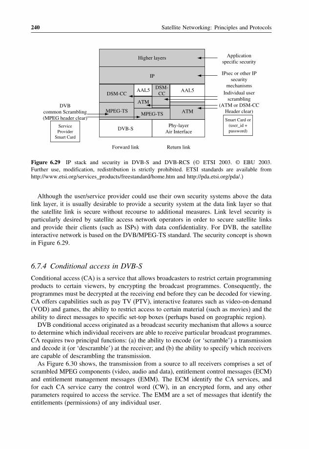
240 Satellite Networking: Principles and Protocols
Higher layers
IP
DVB-S
DSM-CC
MPEG-TS ATMMPEG-TS
AAL5AAL5
ATM
DSM-CC
Phy-layerAir Interface
Forward link Return link
Application specific security
IPsec or other IPsecurity
mechanismsIndividual user
scrambling(ATM or DSM-CC
Header clear)DVB
common Scrambling (MPEG header clear)
Service Provider
Smart Card
Smart Card or (user_id + password)
Figure 6.29 IP stack and security in DVB-S and DVB-RCS (© ETSI 2003. © EBU 2003.Further use, modification, redistribution is strictly prohibited. ETSI standards are available fromhttp://www.etsi.org/services_products/freestandard/home.htm and http://pda.etsi.org/pda/.)
Although the user/service provider could use their own security systems above the datalink layer, it is usually desirable to provide a security system at the data link layer so thatthe satellite link is secure without recourse to additional measures. Link level security isparticularly desired by satellite access network operators in order to secure satellite linksand provide their clients (such as ISPs) with data confidentiality. For DVB, the satelliteinteractive network is based on the DVB/MPEG-TS standard. The security concept is shownin Figure 6.29.
6.7.4 Conditional access in DVB-S
Conditional access (CA) is a service that allows broadcasters to restrict certain programmingproducts to certain viewers, by encrypting the broadcast programmes. Consequently, theprogrammes must be decrypted at the receiving end before they can be decoded for viewing.CA offers capabilities such as pay TV (PTV), interactive features such as video-on-demand(VOD) and games, the ability to restrict access to certain material (such as movies) and theability to direct messages to specific set-top boxes (perhaps based on geographic region).DVB conditional access originated as a broadcast security mechanism that allows a source
to determine which individual receivers are able to receive particular broadcast programmes.CA requires two principal functions: (a) the ability to encode (or ‘scramble’) a transmissionand decode it (or ‘descramble’) at the receiver; and (b) the ability to specify which receiversare capable of descrambling the transmission.As Figure 6.30 shows, the transmission from a source to all receivers comprises a set of
scrambled MPEG components (video, audio and data), entitlement control messages (ECM)and entitlement management messages (EMM). The ECM identify the CA services, andfor each CA service carry the control word (CW), in an encrypted form, and any otherparameters required to access the service. The EMM are a set of messages that identify theentitlements (permissions) of any individual user.

Internet Protocol (IP) over Satellite Networks 241
Component (video, audio, data) in clear
Scramble Descramble
Encipher CW Decipher CW
Control Word (CW)
ECM (information related to services)
Encipher key Decipher key
EMM (information related to a user or groups of users)
Scrambled component
Management keysTransmission
Componentin clear
Figure 6.30 DVB conditional access
In addition, the subscriber management system (SMS) maintains and stores commer-cial aspects of customer relationships (registration, granting of entitlements, invoicing andaccounting), and the subscriber authorisation system (SAS) encrypts code words and deliversthem to the descrambler.At the receiving end, it is the job of the set-top box (STB) to descramble the CA encryption
and decode the MPEG-2 streams for viewing. Each packet has associated with it (in itsheader) a program identifier (PID). The conditional access table (CAT) has a well-knownPID value = 1. This table can be used to identify the PID values of the transport packetscontaining the EMM. The de-multiplexer processor also constructs the program map table(PMT) from non-encrypted packets; this gives the PID values of all the transport streamsassociated with a particular programme. Private data associated with the programme can alsobe included in this table, for example, the PID value of the packets that contain ECM. Allthese tables (signalling messages) are transmitted in the clear, which is an inherent securityweakness in DVB-S systems.
6.7.5 DVB-RCS interactive service and IP over DVB
The interactive satellite architecture consists of a ground station (hub), one or more satellitesin the forward direction, a satellite interactive terminal (return channel satellite terminal,RCST) at the user’s location and a satellite in the return direction.The forward path carries traffic from the ISP to the individual user, and it is multiplexed
into a conventional DVB/MPEG-2 broadcast stream at a broadcast centre (the hub) andrelayed to the RCST. Figure 6.31 shows the protocol stack and Figure 6.32 shows multi-protocol encapsulation (MPE) for IP over DVB.The return channel path operates as part of a digital network, with the hub station providing
the gateway to other (satellite and terrestrial) networks. The satellite terminal employsa scheduled MF-TDMA scheme to access the network and participate in bi-directionalcommunications. MF-TDMA allows a group of terminals to communicate with a hub usinga set of carrier frequencies, each of which is divided into time slots. There are four types of

242 Satellite Networking: Principles and Protocols
TCP
IP
MPE
MPEG-TSCoding &
QPSK
TCP
IP
MPE
MPEG-TS
Coding &QPSK
TCP
IP
IP
PPP
Modem
TCP
IP
IP
PPP
Modem
Server ServerClient ClientDVB PacketEncapsulation
Routerat Hub Site
Tunnel
Figure 6.31 DVB-S and DVB-RCS protocol stack
MPEG Transport Stream(MPEG-TS)
0x3E(8bits)
Length(12 bits)
MAC address(byte 6 & 5)
FSection number& last section
number (16 bits)
OptionalLLC SNAP
IP datagramor LLC frame
PaddingCRC-32 orChecksum
Section syntax indicator& Private indicator (2 bits)
R
Reserved (2 bits each)
R C C
Payload & Addressscrambling control (4 bits)
Flag(1 bit)
MAC address(byte 4, 3, 2 & 1)
1
Flag = 1
DVB Datagram Section
Figure 6.32 IP over DVB: multi protocol encapsulation (MPE)
bursts: traffic (TRF), acquisition (ACQ), synchronisation (SYNC) and common signallingchannel (CSC).There is a new development on DVB-RCS with satellite on-board processors for DVB
streams de-multiplexing and re-multiplexing. In the future, the Ka band will be exploredfor higher capacity and smaller antenna sizes; there will be tighter integration with IPtechnology, protocols and architecture including network management and IP security overthe satellite link; and there will also be more integration between DVB and UMTS, wherethe two systems can complement each other.
6.7.6 DVB-RCS security
The DVB-RCS standard provides much more advanced security procedures (in comparisonto DVB-S CA), which enable satellite terminal authentication and key exchanges with anetwork control centre (NCC).DVB-RCS security can be divided into two phases: phase 1 is the authentication during
the logon procedure. During this phase a security session key is agreed between the satelliteterminal and the NCC. In phase 2, the session key is used for the encryption of all subsequentmessages between UES and NCC. The authentication is based on a long-term secret shared

Internet Protocol (IP) over Satellite Networks 243
between NCC and UES, called a cookie, which is 160 bits long and stored in non-volatilestorage (such as a smart card). The NCC maintains a database of the cookie values of theUES on its network. Cookie values can be updated occasionally as dictated by securitypolicy, but they are less vulnerable than session keys. Anti-cloning measures can also beimplemented using message sequence numbering.A separate consideration is security of the space segment. In satellite systems with DVB
on-board switching, message integrity between the NCC and the OBP is important tomake sure that configuration messages originate from the NCC. The major constraint inthe OBP is its limited memory and computational power, since the computational costof message integrity can be high. This cost depends on the type of algorithms used: forexample, message integrity can be provided using public-key digital signatures, which arecomputationally heavy, or using MAC (message authentication code) with secret keys, whichare computationally lighter. The use of secret keys implies the need for a key agreement,where keys can be stored in the OBP at installation time or agreed using the DVB-RCS keyexchange mechanisms.
6.7.7 DVB security and IP multicast security
DVB-S conditional access is used today for digital broadcasting over satellite and canalso be used to secure multicast communications over satellites at the MPEG-TS level.Descrambling in DVB-S is programme-based, where a whole programme will be scrambledwith the same CW. In a TV broadcast, the programme may contain video, audio and data,each with a specific PID; for IP transmission, the IP datagrams are encapsulated using MPEand transmitted on a specific PID. The main drawback is that the DVB-S scrambling systemfavours a centralised ECM and EMM, and its use for dynamically changing the IP of amulticast group is limited.The number of PIDs is limited to 8192, and if there is one PID per multicast group this
could easily constrain the total number of IP multicast groups that the satellite supports: thealternative is to support several multicast groups per PID, or all groups on a single PID.On the other hand, the DVB-RCS standard provides more advanced security proceduresfor satellite terminal authentication and key exchanges with the satellite network operator.However, it does not provide security procedures for terminal-to-terminal communications(the ‘mesh’ scenario of Figure 6.13). DVB-RCS only allows a single key per terminal, andtherefore does not allow different multicast groups to be encrypted with different keys.
6.8 Internet quality of service (IP QoS)
The original Internet protocol (IP) was design for connectionless networks with best effortto deliver IP packets across the Internet. Best effort means no QoS requirement. In the nextgeneration Internet, best effort is not good enough. It needs to provide new services andapplications with different classes of QoS including guaranteed QoS and controlled loadQoS, in addition to the best-effort services. These presented great challenges to the newgeneration network to provide IP-related QoS. Important network QoS parameters includeend-to-end delay, delay variation and packet loss. These have to be measured in an end-to-end reference path, where the propagation delay of satellite links should be taken intoaccount properly.

244 Satellite Networking: Principles and Protocols
There are many issues on IP-based networks and services defined by the ITU-T (G.1000),which take into account:
• Dynamic allocations of resources (like packet loss and delay) among network segments.• Assuring that required end-to-end network performance objectives are achieved.• Seamless signalling of desired end-to-end QoS across both network and end-user interfaces.• Performance monitoring of IP-based networks and services.• Rapid and complete restoration of IP layer connectivity following severe outages (orattacks) of heavily loaded networks.
The ITU-T (Y.1540) defines parameters that may be used in specifying and assessing theperformance of speed, accuracy, dependability and availability of IP packet transfer of interna-tional IP data communication services. The defined parameters apply to end-to-end, point-to-point IP service and to the network portions that provide such service. Connectionless transportis a distinguishing aspect of the IP service that is considered in this recommendation.The end-to-end IP service refers to the transfer of user-generated IP datagrams (i.e. IP
packets) between two end hosts as specified by their complete IP addresses.
6.8.1 Layered model of performance for IP service
Figure 6.33 shows the layered model of performance for IP service. It illustrates the layerednature of the performance of IP service. The performance provided to IP service usersdepends on the performance of other layers:
• Lower layers that provide (via ‘links’) connection-oriented or connectionless transportsupporting the IP layer. Links are terminated at points where IP packets are forwarded(i.e., routers or switches) and thus have no end-to-end significance. Links may involvedifferent types of technologies, for example, ATM, SDH, PDH, mobile and wireless etc.
Y.1540_F02
RouterSRC Link
IP layer
IP packetLayer serviceperformance
Y.1540
(TCP) (UDP)
(FTP)(RTP)
(HTTP)
etc.
IP layer
LL
Higher layerperformance
User information(e.g., data)
Lower layerperformance(3 instances)
Networkcomponents:
LL LL
Link Router Link DST
IP layer IP layer
(TCP)(UDP)
(FTP)(RTP)
(HTTP)etc.
User information(e.g., data)
Figure 6.33 Layered model of performance for IP service (ITU-T, Y.1540) (Reproduced with thekind permission of ITU.)

Internet Protocol (IP) over Satellite Networks 245
• The IP layer that provides connectionless transport of IP datagrams (i.e., IP packets).The IP layer has end-to-end significance for a given pair of source and destination IPaddresses. Certain elements in the IP packet headers may be modified by networks, butthe IP user data may not be modified at or below the IP layer.
• Higher layers, supported by IP, that further enable end-to-end communications. Upperlayersmay include, for example, TCP,UDP, FTP,RTP,RTCP, SMTPandHTTP.The higherlayers will modify and may enhance the end-to-end performance provided at the IP layer.
6.8.2 IP packet transfer performance parameters
IP packet transfer delay (IPTD) is defined by the ITU-T (Y.1540) for all successful anderrored packet outcomes across a basic section or a network section ensemble (NSE). IPTDis the time t2− t1 between the occurrence of two corresponding IP packet reference events,ingress event IPRE1 at time t1 and egress event IPRE2 at time t2, where t2 > t1 andt2 − t1 ≤ Tmax. If the packet is fragmented within the NSE, t2 is the time of the finalcorresponding egress event. The end-to-end IP packet transfer delay is the one-way delaybetween the MP at the SRC and DST as illustrated in Figure 6.34.Mean IP packet transfer delay is the arithmetic average of IP packet transfer delays used
as an indicator of overall performance.End-to-end two-point IP packet delay variation (IPDV) is the variation in IP packet
transfer delay. Streaming applications might use information about the total range of IPdelay variation to avoid buffer underflow and overflow. Variations in IP delay will cause
Y.1540_F08
EL and NS
(exit)
(exit)
(exit)
(entry)
(entry)
(entry)
ingresseventt1 (exit)
egressevent t2(entry)
ELNSNSELNSEL
MP1 MP2 MP3 MP4 MP5 MPn – 2 MPn – 1 MPn
SRC DST
Figure 6.34 IP packet transfer delay events [ITU-Y.1540] (illustrated for the end-to-end transfer ofa single IP packet) (Reproduced with the kind permission of ITU.)

246 Satellite Networking: Principles and Protocols
TCP retransmission timer thresholds to grow and may also cause packet retransmissions tobe delayed or packets to be retransmitted unnecessarily.IP packet error ratio (IPER) is the ratio of total errored IP packet outcomes to the total
of successful IP packet transfer outcomes plus errored IP packet outcomes in a populationof interest.IP packet loss ratio (IPLR) is the ratio of total lost IP packet outcomes to total transmitted
IP packets in a population of interest. Metrics for describing one-way loss patterns is statedin IETF RFC3357. Consecutive packet loss is of particular interest to certain non-elasticreal-time applications, such as voice and video.Spurious IP packet rate at an egress MP is the total number of spurious IP packets
observed at that egress MP during a specified time interval divided by the time intervalduration (equivalently, the number of spurious IP packets per service-second).IP packet severe loss block ratio (IPSLBR) is the ratio of the IP packet severe loss block
outcomes to total blocks in a population of interest. This parameter can identify multiple IPpath changes due to routing updates, also known as route flapping, which cause significantdegradation to most user applications.
6.8.3 IP network performance objectives for QoS classes
ITU-T recommendation Y.1540 addresses the topic of network transfer capacity (the effectivebit rate delivered to a flow over a time interval), its relationship to the packet transferQoS parameters and objectives specified for each QoS class. The IP network performanceobjectives are shown in Table 6.1.
Table 6.1 Provisional IP network QoS class definitions and network performance objectives(Y.1540)
Networkperformanceparameter
Nature ofnetworkperformanceobjective
QoS classes
Class 0 Class 1 Class 2 Class 3 Class 4Class 5Unspecified(U)
IPTD Upper boundon the meanIPTD
100ms 400ms 100ms 400ms 1 s U
IPDV Upper boundon the 1−10−3
quantile ofIPTD minusthe minimumIPTD
50ms 50ms U U U U
IPLR Upper boundon the packetloss probability
10−3 10−3 10−3 10−3 10−3 U
IPER Upper bound 1×10⁻⁴ 1×10⁻⁴ 1×10⁻⁴ 1×10⁻⁴ 1×10⁻⁴ U
(Reproduced with the kind permission of ITU).

Internet Protocol (IP) over Satellite Networks 247
Table 6.2 Guidance for IP QoS classes (Y.1541)
QoSclass
Applications (examples) Node mechanisms Network techniques
0 Real-time, jitter sensitive,high interaction (VoIP, VTC)
Separate queue withpreferential servicing, trafficgrooming
Constrained routing anddistance
1 Real-time, jitter sensitive,interactive (VoIP, VTC).
Less constrained routingand distances
2 Transaction data, highlyinteractive (signalling)
Separate queue, drop priority Constrained routing anddistance
3 Transaction data, interactive Less constrained routingand distances
4 Low loss only (shorttransactions, bulk data, videostreaming)
Long queue, drop priority Any route/path
5 Traditional applications ofdefault IP networks
Separate queue (lowestpriority)
Any route/path
(Reproduced with the kind permission of ITU).
Transfer capacity is a fundamental QoS parameter having primary influence on the perfor-mance perceived by end users. Many user applications have minimum capacity requirements;these requirements should be considered when entering into service agreements. Y.1540does not define a parameter for capacity; however, it does define the packet loss parameter.Lost bits or octets can be subtracted from the total sent in order to provisionally determinenetwork capacity.Theoretically, IP over satellite networks is not able to provide Class 0 or 2 services (refer
to Table 6.2), due to their real-time characteristics, but the advantage factor of satelliteshould be taken into consideration.
6.8.4 Guidance on IP QoS class usage
Table 6.2 gives some guidance for the applicability and engineering of the network QoSclasses (Y.1541). To support QoS there are two architectures that are defined by the IETF:integrated services (commonly known as Intserv) and differentiated services (commonlyknown as Diffserv).
6.9 Integrated services (Intserv) architectures for QoS
Within the Internet, each node (switch or router) deals with protocols up to the IP layerpacket. The Internet provides only best-effort IP datagram transmission. IP packets are sentfrom a source to a destination without any guarantee that the packet will reach its destination.It is only suitable for elastic applications that tolerate packet delays and packet losses; the
248 Satellite Networking: Principles and Protocols
best-effort model at the network layer is compensated by the TCP at the transport layerintroduced in the end systems (clients or servers) to provide reliability by acknowledgementsand retransmission mechanisms.However, the emerging real-time applications have very different characteristics and
requirements to data applications. They are inelastic, hence are less tolerant of delay variationand need specific network conditions in order to perform well. To support the range of QoS,the IP architecture has to be extended to provide support for real-time services.
6.9.1 Integrated services architecture (ISA) principles
The primary goal of the integrated services architecture (ISA) and QoS model is to provideIP applications with end-to-end ‘hard’ QoS guarantees, where the application may explicitlyspecify its QoS requirements and these will be guaranteed by the network.The Intserv architecture is a framework developed within the IETF to provide individu-
alised QoS guarantees to individual application sessions (RFC1633). It is a reservation-basedQoS architecture, designed to guarantee fair sharing of resources (both link bandwidth androuter buffers) among users by dynamically controlling and managing the bandwidth viaresource reservation and admission control. It uses the resource reservation protocol (RSVP)(RFC2475) as the signalling mechanism for specifying an application’s QoS requirementsand identifying the packets to which these requirements apply. The two key features of theIntserv architecture are:
• Reserved resources: routers need to know the amounts of resources (link bandwidth andbuffers) already reserved for ongoing sessions, and available for allocations.
• Session set up: a session must reserve sufficient resources at each network router fromsource-to-destination path to ensure that its end-to-end QoS requirement is met. This callset up (also known as call admission) process requires the participation of each routeron the path. Each router must determine the local resources required by the session,consider the amount of its resources that are already committed to other ongoing sessions,and determine whether it has sufficient resources to satisfy the QoS requirement withoutviolating local QoS guarantees.
The building blocks relevant to the Intserv approach are resource reservation, admissioncontrol, traffic classification, traffic policing, queuing and scheduling.There are two types of routers: edge router (ER) and core router (CR). The functions
of ER are to control flows into the network domain, including explicit per-flow admissioncontrol, per-flow classification, per-flow signalling and per-flow resource reservation. Thefunctions of CR are to forward the IP packets as fast as possible, based on information inthe IP packets set by the ER.In order for a router to determine whether or not its resources are sufficient to meet the
QoS requirements of a session, that session must first declare its QoS requirement, as wellas characteristics of the traffic. The signalling entity request specification (R_Spec) definesthe specific QoS being requested by a connection; traffic specification (T_Spec) on the otherhand characterises the traffic. The RSVP protocol is currently the signalling protocol of forthis purpose.

Internet Protocol (IP) over Satellite Networks 249
A session (application) is only allowed to send its data once its request for resources isgranted. It is also important that granting a request must not be at the expense of othercommitments already in place. A successful reservation request results in installation ofstates at RSVP-aware nodes. As long as the application honours its traffic profile, thenetwork meets its service commitments by maintaining per-flow states and using queuingand scheduling disciplines.
6.9.2 The resource reservation protocol (RSVP)
RSVP is the signalling protocol used in the Intserv model to reserve network resources(bandwidth and buffer space) for their data flows. RSVP requests are carried through thenetwork, visiting each node along the routed path used to the destination. At each node(router), RSVP attempts to reserve resources for the particular flow. Hence, RSVP softwaremust run in the hosts (senders and receivers) and the routers. It is also a flow-based protocol,i.e. classification is done on each and every flow. Resources reserved need to be refreshedwithin a specified time limit – otherwise the resources are released upon the expiry of thistime interval. This is also known as a ‘soft-state’ reservation. The two key characteristics ofRSVP are:
• It provides reservation for bandwidth in multicast applications such as audio/video con-ferencing and broadcasting. It is also used for unicast traffic, however, unicast requestsare handled as a special case.
• It is receiver-oriented, i.e. the receiver of the data flow initiates and maintains the resourcereservation used for that flow.
There are two main components of RSVP – the packet classifier and the packet schedulerinstalled on the host to make QoS decisions about the packets sent in by applications. Thecommunications among various components existing in an RSVP-enabled host and router isas shown in Figure 6.35. RSVP reserves bandwidth and advises the network on the correctqueue management and packet discard policies. RSVP-enabled routers will then invoke theiradmission control and packet-scheduling mechanisms based on the QoS requirements. Theadmission control module decides whether or not there are enough resources locally to grantthe reservation without violating resources already committed to existing connections. Thepacket-scheduling module is a key component because this is the module that manifests thedifferent services to different flows.RSVP first queries the local decision modules to find out whether the desired QoS can
be provided (this may involve resource-based decisions as well as policy-based decisions).It then sets up the required parameters in the packet classifier and the packet scheduler.The packet classifier implements the process of associating each packet with the appropriatereservation so that it can be handled correctly. This classification is done by examining thepacket header. The packet classifier also determines the route of the packet based on theseparameters. The scheduler makes the forwarding decisions to achieve the desired QoS. Whenthe link layer at the host has its own QoS management capability, then the packet schedulernegotiates with it to obtain the QoS requested by RSVP. In the other case, for example, whenthe host is using a leased line, the scheduler itself allocates packet transmission capacity. Itmay also allocate other system resources like CPU time, buffers, etc.

250 Satellite Networking: Principles and Protocols
Host Router
Application
Sche
dule
r
… Sche
dule
r
DataCla
ssif
ier
RSVPprocess
Admissioncontrol
Policy control
Cla
ssif
ier
Admissioncontrol
Routingprocess
RSVP process
Policy control
RSVP
Figure 6.35 Interaction between the different RSVP components
Two basic messages used in RSVP are the PATH and RESV messages. A PATH messageis initiated by the sender and is addressed directly to the destination. It sets up statesalong the path to be followed by the application packets from the sender to the specifieddestination. This path is determined by the underlying routing protocol. A PATH messageincludes information such as the previous hop (the previous RSVP-aware entity on the path),the sender’s T_Spec and ADSPEC (the advertising specification used to capture the pathcharacteristics). At each router along this path, a local RSVP entity updates these parametersin its memory and amends some of the information carried by the PATH message.Upon receiving the PATH message, the receiver will decide whether or not to actually
receive the data from the sender. Should it wish to continue with the session the receiverconstructs a RESV message based on the advertisement information carried by the PATHmessage and sends this message back towards the sender along the path already set up.Routers along the path will then invoke their RSVP processes and reserve the requiredresources extracted from the receiver’s R_Spec information contained in the RESV message.When the receiver has successfully reserved resources over the entire path, a success messageis returned. The same RESV message is sent about once every 30 s should the receiver wishto retain the reservation. If any one router rejects the reservation, the request is denied andan error message is generated. Resources already reserved at intermediate nodes will thenbe released.RSVP is not a routing protocol and it does not perform its own routing. Like any other IP
traffic, it relies on the underlying IP routing protocols to determine the path for both its dataand control traffic. As the routing information adapts to network topology changes (due tolink or router failure), RSVP reservations are carried over to the new path calculated by therouting protocols. This flexibility helps RSVP to function effectively with current and futureunicast or multicast routing protocols. It is specially suited for multicast applications – RSVPscales to very large multicast groups because it uses receiver-oriented reservation requeststhat merge as they progress up the multicast tree. If the RESV message arrives at a routerwhere the desired QoS reservation (or one greater) is already in place for another receiver

Internet Protocol (IP) over Satellite Networks 251
in the same multicast group, then the RESV message need not travel any further. The two(or more) receivers can share the reservation.
6.9.3 Intserv service classes
In terms of QoS support, Intserv defines two classes of service, in addition to the existingbest-effort service (BES): guaranteed services (GS) and controlled load services (CLS).Typically, the total capacity is divided and allocated in proportions to accommodate thethree different service classes.
• Guaranteed service (GS). It guarantees firm bounds (mathematically provable) on themaximum end-to-end packet delay by reserving a rate at each router. It guarantees thatpackets will arrive within the requested delivery time and will not be discarded due toqueue overflows (provided the flow’s traffic conforms to the specified traffic parameters).This service is designed for applications requiring a fixed amount of delay.GS traffic must be policed at the network access points to ensure conformance to theT_Spec. Non-conforming packets are usually forwarded as BES traffic. GS also requirestraffic shaping and any packets failing this process will be forwarded as BE traffic.
• Controlled load service (CLS). It allocates resources such that a high proportion of trafficusing this service will experience conditions very close to an uncongested network. CLSaims to emulate a lightly loaded network although the network as a whole may in factbe heavily loaded. In other words, the session may assume that a ‘very high percentage’of its packets will successfully pass through the router without being dropped and willexperience a queuing delay in the router under a light load condition.
• Best-effort service (BES). This is the service provided by the current Internet.
An important difference between CLS and BES is that CLS does not noticeably deteri-orate as the network load increases and regardless of the level of load increase. BES onthe other hand will experience progressively worse service as the network load increases.However, CLS makes no quantitative guarantees about performance – it does not specifywhat constitutes a ‘very high percentage’ of packets or what QoS closely approximates thatof an unloaded network element.CLS also requires traffic policing. Non-conforming CLS flows must not be allowed to
affect the QoS offered to conforming CLS flows or to unfairly affect the handling of BEStraffic.
6.10 Differentiated services (Diffserv) for QoS
Diffserv allows IP traffic to be classified into a finite number of priority and/or delayclasses. Traffic classified as having a higher priority and/or delay class receives some formof preferential treatment over traffic classified into a lower class. The differentiated servicesarchitecture (DSA) does not attempt to give explicit ‘hard’ end-to-end guarantees. Instead, atcongested routers, the aggregate of traffic flows with a higher class of priority has a higherprobability of getting through.

252 Satellite Networking: Principles and Protocols
6.10.1 DSA principles
The DSA approach is intended to provide scalable and flexible service discrimination with-out the signalling overhead or significant changes to the Internet infrastructure as required bythe Intserv/RSVP architecture. This approach aims to provide the ability to handle different‘classes’ of traffic in different ways within the Internet. The need for scalability arises fromthe fact that hundreds of thousands of simultaneous source–destination traffic flows may bepresent at backbone networks. The need for flexibility arises from the fact that new serviceclasses may appear and old service classes may become obsolete. The Diffserv architectureis flexible in the sense that it does not define specific services or service classes (e.g., as isthe case with Intserv). Instead, the Diffserv architecture provides the functional components,within the network architecture, to allow such services to be built.There is no reservation in the Diffserv QoS architecture. It provides differential treatments
to a consolidation of flows where traffic is aggregated into groups or classes throughout thenetwork. This approach consists of marking packets by setting bits in the packet header,specifically the type of service (TOS) field in the IPv4 packets and the traffic class fieldin IPv6 packets (Figure 6.36). In the TOS byte structure as shown below, the first threebits represents the precedence bits and can be used to indicate need for a low delay or highthroughput or low loss rate service. MBZ is the must be zero bit. This byte is renamed toDS field in Diffserv and has the following structure (Figure 6.37).The first six bits of the DS field is known as the differentiated services code point (DSCP);
the last two bits are currently unused (CU). By setting these bits appropriately, differentservices requiring different treatment will be ‘tagged’ with different priority levels. Thisdifferentiation allows the network (routers) to recognise the type of service required andhandle the packets accordingly, usually by some form of priority queuing management andpacket scheduling schemes. Note that the key approach here is the use of packet headersto carry information required by these schemes, hence eliminating the need for signallingprotocols to control the mechanisms that are used to select different treatments for theindividual packets. As a result, the requirement for maintaining state information at everynode is reduced substantially – the amount of information needed is now proportional tothe number of services instead of the number of application flows, as is the case withIntserv.
Precedence Type of Services (TOS) MBZ
0 1 2 3 4 5 6 7
Figure 6.36 Type of service (TOS) field
Differentiated Services Code Point (DSCP) CU
0 1 2 3 4 5 6 7
Figure 6.37 Differentiated service (DS) field

Internet Protocol (IP) over Satellite Networks 253
The architectural framework of the Diffserv approach consists of two sets of functionalelements:
• Edge functions: packet marking (classification) and traffic conditioning. These functionsare implemented at the incoming edge of the network (ingress) i.e. either at a Diffserv-capable host that generates traffic or at the first Diffserv-capable router that the trafficpasses through. Packets entering the network will be marked, i.e. the first six bits of theDS field of the packet’s header is set to some value. The mark that the packet receivesdepends on the measured temporal properties of the flow the packet belongs to andcompared against a predefined traffic profile. The mark identifies the class of traffic ormore specifically the behaviour aggregate (BA) the packet belongs to. Different behaviouraggregates will then receive different treatments or service within the core network (theDiffserv domain). After being marked, the packet may be allowed entry into the networkimmediately, delayed for some time before being forwarded or discarded altogether. Thisis performed by the traffic conditioning function to ensure compliance to the predefinedprofile.
• Core function: forwarding. When a DS-marked packet arrives at a Diffserv-capable router,the packet is forwarded onto its next hop according to the so-called per-hop behaviour(PHB) associated with that packet’s BA. The per-hop behaviour influences how a router’sbuffers and link bandwidth are shared among the competing classes of traffic. A crucialtenet of the Diffserv architecture is that a router’s PHB will be based only on packetmarkings, i.e. the class of traffic to which a packet belongs. It will not distinguish packetsbased on source–destination address. The implication of this approach is that the corerouters will no longer need to keep state information for source–destination pairs – animportant consideration when meeting the scalability requirement.
In essence, the Diffserv architecture defines three main components: the traffic classifiers,which select packets and assigns their DSCP values; the traffic conditioners, which markand enforce rate limitations; and the PHB, which enforces differentiated packet treatments.Before differentiated services can be extended across a Diffserv network domain, a service
level agreement (SLA) is first established between the subscriber and the network/serviceprovider. The SLA basically establishes the policy criteria and defines traffic profiles. Amongothers, an SLA contains policies such as monitoring provisions, billing and accounting agree-ments and availability levels. However, one key subset of the SLA is the traffic conditioningagreement (TCA). The TCA defines traffic profiles, performance metrics (e.g. throughput,latency and drop probability) and instructions on how both in- and out-of-profile packets(with respect to the agreed traffic profile) are to be handled. The contents of the SLA, espe-cially the TCA, will be used by both the subscriber when submitting traffic to the network,and the network/service provider when handling the submitted traffic.
6.10.2 Traffic classification
Traffic classification is an important function to be undertaken at the Diffserv network pointof entry (ingress). The purpose of this function is to identify packets belonging to a certainclass that may receive differentiated services. From the classification result, traffic profileand the corresponding policing, marking and shaping rules of the incoming packets can be

254 Satellite Networking: Principles and Protocols
derived. Packet classification is done by the packet classifier. The classifier selects packetsbased either on the DSCP only or a combination of one or more header fields. The first ofthese classifiers is known as the BA classifier and the second the multi-field (MF) classifier.Once the packets are classified, they are steered to the appropriate marking function wherethe DS field value of the packets is set accordingly.
6.10.3 Traffic conditioning
A traffic conditioner is an entity that applies some traffic control function to incomingpackets to ensure the traffic flow adheres to the TCA rules. These functions include:
• Marking i.e. setting the DSCP in a packet that has already been classified, based onwell-defined rules.
• Metering, which compares the incoming packets with the negotiated traffic profile anddetermines whether the packet is within the negotiated traffic profile or not. It will thendecide whether to re-mark, forward, delay or drop a packet even though the actual decisionon what to do to a packet is not defined in the Diffserv architecture. The aim is to makethe Diffserv components flexible enough to accommodate a wide and constantly evolvingset of services.
• Shaping, which delays packets within a traffic stream to cause the stream to conform tothe negotiated traffic profile.
• Shaper or dropper, which discards packets based on specified rules e.g. when the trafficstream violates the negotiated traffic profile.
A logical view of these components is shown in Figure 6.38.
6.10.4 Diffserv per hop behaviour (PHB)
The third set of Diffserv functional element is the packet forwarding function performed bythe core Diffserv-capable routers. This forwarding function known as the per hop behaviour
Boundary node
Classifier Shaper/Dropper
Marker
TCA SLA
Sche
dule
r
Interior node
Buffer management(per class)
Per Hop BehaviourTraffic Conditioner
ClassifierMeter
Figure 6.38 Logical view of Diffserv components

Internet Protocol (IP) over Satellite Networks 255
(PHB) is defined as ‘a description of the externally observable forwarding behaviour ofa Diffserv node applied to a particular Diffserv behaviour aggregate’. There are severalimportant considerations embedded within this definition:
• A PHB can result in different classes of traffic (i.e., traffic with different DS fieldvalues) receiving different performance (i.e., different externally observable forwardingbehaviour).
• While a PHB defines differences in performance (behaviour) among classes, it doesnot mandate any particular mechanism for achieving these behaviours. As long as theexternally observable performance criteria are met, any implementation mechanism andany buffer/bandwidth allocation policy can be used. For example, a PHB would not requirethat a particular packet queuing discipline, e.g., a priority queue versus a weighted-fair-queuing queue versus a first-come-first-served queue, be used to achieve a particularbehaviour.
• Differences in performance must be observable, and hence measurable.
An example of a simple PHB is one that guarantees that a given class of marked packetsreceives at least a certain percentage of the outgoing link bandwidth over some interval oftime. Another PHB might specify that one class of traffic will always receive strict priorityover another class of traffic, i.e. if a high priority packet and low priority packet are presentin a router’s queue at the same time, the high priority packet will always leave first.Diffserv defines a base set of PHB. These PHB are in turn defined by a set of forwarding
behaviour that each router along the path adheres to, i.e. each PHB would correspond toa particular forwarding treatment given to the packets, implemented by means of buffermanagement and packet scheduling mechanisms. There are currently three proposed PHBs:
• The default (DE) PHB is equivalent to the best-effort forwarding already existing intoday’s IP networks. Packets marked with this service are sent into the network withoutadhering to any particular rules and the network will deliver as many of these packets aspossible as soon as possible without any performance guarantees.
• The expedited forwarding (EF) PHB specifies that the departure rate of a class of trafficfrom a router must equal or exceed a configured rate. That is, during any interval of time,the class of traffic can be guaranteed to receive enough bandwidth so that the output rate ofthe traffic equals or exceeds this minimum configured rate. Note that the EF PHB impliessome form of isolation among traffic classes, as this guarantee is made independently ofthe traffic intensity of any other classes that are arriving to a router. Thus, even if the otherclasses of traffic are overwhelming router and link resources, enough of those resourcesmust still be made available to the EF class to ensure that it receives its minimum rateguarantee. It assures bandwidth availability regardless of the number of flows sharing thelink. EF PHB thus provides a class with the simple abstraction of a link with a minimumguaranteed link bandwidth. It can be used to build an end-to-end service that requireslow loss, low delay, low jitter and assured bandwidth service (also known as premiumservice). It essentially emulates a virtual leased line.
• The assured forwarding (AF) PHB is more complex. AF PHB divides traffic into fourclasses, where each AF class is guaranteed to be provided with some minimum amount ofbandwidth and buffering. Within each class, packets are further partitioned into one of three

256 Satellite Networking: Principles and Protocols
‘drop preference’ categories. When congestion occurs within an AF class, a router can thendiscard (drop) packets based on their drop preference values. Low drop precedence packetsare protected from loss by preferentially discarding higher drop precedence packets. Byvarying the amount of resources allocated to each class, an ISP can provide differentlevels of performance to the different AF traffic classes.
Because there are only three PHBs or traffic classes, only the first three bits of the DSCPare needed to denote the traffic class a packet belongs to; the remaining three bits are set tozero. Out of the first three bits, the first two are actually used to denote the traffic class. Thisis then used to select the appropriate queue (each traffic class is allocated its own queue atthe output port). The third bit is used to indicate the drop preference inside each queue/class.As mentioned previously, the Diffserv architecture only defines the DS and PHB fields
of a packet header. It does not mandate any specific implementation mechanisms in order toachieve the service differentiation. The service provider will have the responsibility and flex-ibility to implement appropriate traffic handling mechanisms that best fit the specific servicedifferentiation they wish to offer. These traffic handling mechanisms are basically traffic fil-tering (classification), queue management and packet scheduling mechanisms. Hence carefuldesign of these mechanisms is needed to ensure the desired service(s) is achievable whilekeeping the design as simple as possible.
6.10.5 Supporting Intserv across the satellite network Diffserv domain
Both Intserv and Diffserv approaches go beyond the best-effort service model by definingsome kind of agreement between the users and the network/service providers. From thisagreement, a ‘service profile’ can then be built and classified according to a specific ser-vice’s spatial and temporal requirements. In terms of the spatial requirements, Intserv/RSVPprovides the maximum detail – the flow to which the agreement applies is fully specifiedfrom the source to the destination and along the path taken. Diffserv, on the other hand,provides a coarser approach – a user may require all or a fraction of his traffic to be givena better service than best effort. In terms of the temporal requirements, again Intserv/RSVPprovides a more flexible approach – dynamic agreements can be set up and released ondemand depending on the need of the user. Diffserv supports a static agreement where theduration of the agreement is defined on a contractual basis between the user and the serviceprovider (in the form of the SLA).Although it is clear the approaches taken by both Intserv and Diffserv are contradictory to
each other, the two architectures can be complementary to each other. Existing alone, Intservwould definitely suffer from the scalability problems – although it promises tightly controlledQoS on an end-to-end basis, its processing overhead is just too much for an Internet of adecent coverage. Diffserv on the other hand, only guarantees QoS on an aggregate basis (perclass basis) – there is no guarantee to the individual flows making up the class.However, by combining the advantages from the two models, it is possible to build a
scalable QoS architecture capable of delivering predictable service guarantees. Diffserv,with its focus on the needs of large networks, can be deployed in high-speed transit net-works. A hybrid architecture can consist of peripheral domains (access networks) that areIntserv/RSVP-aware interconnected by a Diffserv core. A typical configuration is shown inFigure 6.39 where the satellite acts a core network to bridge the access networks.

Internet Protocol (IP) over Satellite Networks 257
Satellite as Core Network
IntServdomain
IntServdomain
RSVP PATH(not processed)
RSVP PATH(processed)
RSVP PATH(processed)
RSVP RESV(not processed)
RSVP RESV(processed)
RSVP RESV(processed)
ER
ER: Edge Router; CR: Core Router;R: RSVP Router; Bandwidth Broker
ER
DiffServ domain
RR
Figure 6.39 Architectural for Intserv networks via satellite Diffserv network
The edge routers at the boundaries of the different network regions would normally bedual function – a standard RSVP function, which interfaces the stub networks and a Diffservfunction, which interfaces the transit network. The RSVP half is capable of processing all theRSVP signalling elements. The Diffserv half functions also work as the admission controllerinto the Diffserv domain. In the simplest scenario, the admission control has informationregarding how much bandwidth has been used and how much is left available. Using thisinformation as parameters in the RESV messages, the edge router is able to determinewhether or not to permit a new connection. If the request is accepted, the traffic is thenmapped to an appropriate PHB and its associated DSCP is marked in the packet header. Itcan be assumed that insert’s GS is mapped to EF PHB and CLS to the highest priority AFPHB.The signalling process for end-to-end QoS is triggered by the sending host generating a
PATH message. On its way towards the receiver, this PATH message is only processed inthe Intserv domains that it passes through. At the edge router straddling the boundaries, thePATH state is installed in the router and the PATH message is carried through the Diffservtransit network unprocessed.Upon receiving the PATH message, the receiver generates a RESV message and this is
sent back to the sender via the same path the PATH message took. The request may ofcourse be rejected while it is still in the stub Intserv domain, according to standard Intservadmission control. At the boundary, the RESV triggers admission control at the edge router.The router compares the requested resources to the corresponding Diffserv service level.The request is approved when there are enough resources and the request fits the SLA. TheRESV message is admitted into the Diffserv transit and continues upstream towards thesender unprocessed. Upon entering the Intserv stub again, normal Intserv processes resumeuntil the RESV message reaches the intended sender. The RESV message terminates at thesender with information regarding the specified traffic flow and its corresponding Diffservservice level.

258 Satellite Networking: Principles and Protocols
Further reading[1] Akyildiz, I.F. et al., Satellite ATM networks: a survey, IEEE Communications, 35(7): 30–43, 1997.[2] Allman, M., Glover, D. and Sanchez, L. Enhancing TCP over Satellite Channels using Standard Mechanisms,
IETF RFC2488, January 1999.[3] Ballardie, A., Core-based Trees (CBT version 2) Multicast Routing, IETF RFC2189, September 1997.[4] Bem, D.J., Wieckowski, T.W. et al., Broadband satellite systems, IEEE Communications, 3(1): 2–14, 2000.[5] Blake, S. et al., An Architecture for Differentiated Services, IETF RFC2475, December 1998.[6] Braden, R., Clark, D. and Shenker, S., Integrated Services in the Internet Architecture: an Overview, IETF
RFC1633, June 1994.[7] Deering, S., Estrin, D.L. et al., The PIM architecture for wide-area multicast routing, IEEE Transactions:
Networking, 4(2): 153–62, 1996.[8] Estrin, D. et al., Protocol-independent Multicast – Sparse Mode (PIM-SM): Protocol Specification, IETF
RFC2362, June 1998.[9] ETSIEN301790.DigitalVideoBroadcasting (DVB) InteractionChannel for SatelliteDistributionSystems, 2000.[10] Fenner, W., Internet Group Management Protocol, Version 2, IETF RFC2236, November 1997.[11] Howarth, M.P., Cruickshank, H. and Sun, Z., Unicast and multicast IP error performance over an ATM
satellite link, IEEE Comms. Letters, 5(8): 340–2, 2001.[12] Howarth,M., Iyngar, S., Sun, Z. and Cruickshank, H., Dynamics of keymanagement in secure satellite multicast,
IEEE Journal on Selected Areas in Communications: Broadband IP Networks via Satellites,Part I, 22(2), 2004.[13] Kent, S. and Atkinson, R., Security Architecture for the Internet Protocol, IETF RFC2401, November 1998.[14] Koyabe, M. and Fairhurst, G., Reliable multicast via satellite: a comparison survey and taxonomy, International
Journal of Satellite Communications, 19(1): 3–28, 2001.[15] Moy, J., Multicast Extensions to OSPF, IETF RFC1584, March 1994.[16] Rosen, E., Viswanathan, A. and Callon, R., Multiprotocol Label Switching Architecture, IETF RFC3031,
January 2001.[17] Sahasrabuddhe, L.H. and Mukherjee, B., Multicast routing algorithms and protocols: a tutorial, IEEE Network,
14(1): 90–102, 2000.[18] Sun, Z., Broadband satellite networking, Space Communications, Special issue on On-Board Processing,
17(1–3): 7–22, 2001.[19] Sun, Z., He, D., Cruickshank, H., Liang, L., Sánchez, A. and Tocci, C., Scalable architecture and evaluation for
multiparty conferencing over satellite links, IEEE Journal on Selected Areas in Communications: BroadbandIP Networks via Satellites, Part II, 22(3), 2004.
[20] Thaler, D., Border Gateway Multicast Protocol (BGMP): Protocol Specification, IETF Draft, work-in-progress,draft-ietf-bgmp-spec-06.txt, 20 January 2004.
[21] Waitzman, D., Partridge, C. and Deering, S. Distance Vector Multicast Routing Protocol, IETF RFC1075,November 1988.
[22] Wallner, D., Harder, E. and Agee, R., Key Management for Multicast: Issues and Architectures, IETFRFC2627, June 1999.
[23] Yegenoglu, F., Alexander, R. and Gokhale, D., An IP transport and routing architecture for next-generationsatellite networks, IEEE Network, 14(5): 32–8, 2000.
[24] RFC 2002, IP Mobility Support, C. Perkins, IETF, October 1996.[25] RFC 1256, ICMP Router Discovery Messages, S. Deering, IETF, September 1991.[26] RFC 1321, The MD5 Message-Digest Algorithm, R. Rivest, IEFT, April 1992.[27] RFC 2627, Key Management for Multicast: Issues and Architectures, D. Wallner, E. Harder and R. Agee,
IETF, June 1999.[28] RFC 3357, One-way Loss Pattern Sample Metrics, R. Koodli and R. Ravikanth, IETF, August 2002.
Exercises
1. Explain the concepts of satellite IP networking.2. Explain IP packet encapsulation concepts of PPP and IP tunnelling.3. Use a sketch to explain the satellite-centric view of the global network and Internet.
Internet Protocol (IP) over Satellite Networks 259
Exercises (continued)
4. Explain IP multicast over satellite.5. Explain DVB and related protocol stack.6. Explain DVB over satellite including DVB-S and DVB-RCS.7. Explain IP over DVB-S and DVB-RCS security mechanisms.8. Discuss IP QoS performance objectives and parameters and QoS architectures of
Intserv and Diffserv.


7Impact of Satellite Networks onTransport Layer Protocols
This chapter aims to discuss the impact of satellite networks on transport layer protocolsincluding the transmission control protocol (TCP) and their applications. TCP is a reliabletransport layer protocol of the Internet protocol stack. TCP provides the protocol for end-to-end communications between a client process in one host and a server process in the other hostin the Internet. TCP has neither information on applications nor information on Internet trafficconditions and the transmission technologies (such as LAN, WAN, wireless and mobileand satellite networks). TCP relies on mechanisms including flow control, error control andcongestion control between the client and server hosts to recover from transmission errorand loss and from network congestion and buffer overflows. All these mechanisms affectthe performance of TCP over satellite and hence the Internet applications directly. Thischapter also explains the major enhancements designed to improve TCP performance oversatellite for a ‘satellite-friendly TCP’, although not all of these enhancements have becomeIETF standards, since they may cause some side-effects on the normal TCP operations. Thischapter also provides an introduction to real-time transport protocols built on top of theUDP including RTP, RTCP, SAP, SIP, etc., and related applications including voice over IP(VoIP) and multimedia conferencing (MMC). When you have completed this chapter, youshould be able to:
• Know the impact of satellite networks on the performance of TCP due to flow control,error control and congestion control mechanisms.
• Carry out a performance analysis on the standard TCP slow-start algorithm and congestionavoidance mechanism, and calculate the utilisation of satellite bandwidth.
• Know the typical mechanisms for TCP-enhancement satellite networks.• Describe TCP enhancement on the slow-start algorithm.
Satellite Networking: Principles and Protocols Zhili Sun© 2005 John Wiley & Sons, Ltd

262 Satellite Networking: Principles and Protocols
• Describe TCP enhancement on the congestion avoidance mechanism.• Describe TCP enhancement on acknowledgement.• Know TCP enhancement on error recovery mechanisms including fast retransmission andfast recovery.
• Learn the interruptive TCP performance acceleration mechanisms including TCP spoofingand cascading TCP (also known as split TCP).
• Understand the impact of satellite networks on different applications.• Understand the limitation of TCP enhancement mechanisms based on existing TCP mech-anisms.
• Understand real-time protocols including RTP, RTCP, SAP, SIP, etc., and their differencesfrom other application layer protocols such as HTTP and SMTP.
• Understand VoIP and MMC based on the real time transport protocols.
7.1 Introduction
TCP is the protocol for end-to-end communications between processes in different hostsacross Internet networks. It is implemented within the client host or server in order toprovide applications with reliable transmission services. It is transparent to the Internet, i.e.the Internet treats it only as the payload of IP packets (see Figure 7.1).The most challenging task of TCP is to provide reliable and efficient transmission services
without knowing anything about applications above it or anything about the Internet belowit. TCP carries out proper actions according to application characteristics, client and serverparameters and network parameters and conditions (particularly satellite networks).
7.1.1 Application characteristics
There is a wide range of applications built on TCP, including remote login, file transfer,email and WWW. The amount of data to be transmitted by TCP can range from a few bytes
Applications
Clie
User terminal
Server processes
Sockets
TCP
IP layer
Network InterfaceCard (NIC)
Server
Applications
IP layer
Network InterfaceCard (NIC)
IP layer
Network InterfaceCard (NIC)
IP over Satellite, Ethernet, Wireless LANs, etc. …
TCP session (end to end)
Client processes
Sockets
TCP
IP layer
Network InterfaceCard (NIC)
Figure 7.1 The TCP protocol over satellite Internet

Impact of Satellite Networks on Transport Layer Protocols 263
to kilobytes, megabytes or even gigabytes. The duration of a TCP session can be as few asa fraction of a second up to many hours. Therefore, the data size of each transaction andtotal data size of each TCP session are important factors affecting TCP performance.
7.1.2 Client and server host parameters
The current Internet applications built on TCP are elastic, i.e. they can tolerant slow processand transmission of their data. It is this feature together with the TCP that allows us to buildthe Internet using different types of computers, from PCs to supercomputers, and enablesthem to communicate with each other.The main parameters affecting TCP performance include the process power (how fast it
can deal with data within the TCP session), buffer sizes (memory space allocated to the TCPsession for data buffering) and speeds of network interface cards (how fast the hosts cansend data to networks) in both client and server hosts, and round trip delay (RTT) betweenthe client and the server.
7.1.3 Satellite network configurations
Satellite can play many different roles in the Internet. Figure 7.2 shows a typical exampleof satellite network configurations with the satellite network in the centre connecting twoterrestrial access networks.For ease of discussion, we assume that all constraints are due to the satellite network
(long delay, errors, limited bandwidth, etc.). Both access networks and interworking units(routers or switches) are capable of dealing with traffic flows between access networks andthe satellite network. The following are some typical satellite network configurations:
• Asymmetric satellite networks: DVB-S, DVB-RCS and VSAT satellite networks areconfigured with bandwidth asymmetry, a larger data rate in the forward direction (from
Applications
User terminal
Server
SatelliteNetwork
Clientaccess
Network
Serveraccess
Network
InterworkingUnit
InterworkingUnit
Satellite Network Configuration
Client processes
Sockets
TCP
IP layer
Network InterfaceCard (NIC)
Applications
Server processes
Sockets TCP
IP layer
Network InterfaceCard (NIC)
Figure 7.2 Example of satellite network configurations

264 Satellite Networking: Principles and Protocols
satellite gateway station to user earth stations) than the return direction (user earth stationsto satellite gateway station), because of limits on the transmission power and the antennasize at different satellite earth stations. Receive-only broadcasting satellite systems areunidirectional and can use a non-satellite return path (such as a dialup modem link viatelephony networks). The nature of most TCP traffic is asymmetric with data flowing inone direction and acknowledgements in the opposite direction.
• Satellite link as last hop: satellite links that provide service directly to end users, asopposed to satellite links located in the middle of a network, may allow for specialiseddesign of protocols used over the last hop. Some satellite providers use the satellite linkas a shared high-speed downlink to users with a lower speed, non-shared terrestrial linkthat is used as a return link for requests and acknowledgements. In this configuration, theclient host has direct access to the satellite network.
• Hybrid satellite networks: in the more general case, satellite links may be located atany point in the network topology. In this case, the satellite link acts as just anotherlink between two gateways. In this environment, a given connection may be sent overterrestrial links (including terrestrial wireless), as well as satellite links. This is a typicaltransit network configuration.
• Point-to-point satellite networks: in point-to-point satellite networks, the only hop in thenetwork is over the satellite link. This is a pure satellite network configuration.
• Multiple satellite hops: in some situations, network traffic may traverse multiple satel-lite hops between the source and the destination. Such an environment aggravates thesatellite characteristics. This is a generic problem with special circumstances or spacecommunications where there are many more constraints due to long delay, error andbandwidth.
• Constellation satellite networks with and without inter-satellite links (ISL): in constel-lation satellite networks without ISL, multiple satellite hops are used for wide coverage. Inconstellation satellite networks with ISL, wide coverage is achieved by ISL. The problemis that the route of the network is highly dynamic hence end-to-end delay is variable.
7.1.4 TCP and satellite channel characteristics
The Internet differs from a single network because it consists of different network topologies,bandwidth, delays and packet sizes. TCP is formally defined in RFC793 and updated inRFC1122 and extensions are given in RFC1323 to work in such heterogeneous networks.TCP is a byte stream, not a message stream and message boundaries are not preserved
end to end. All TCP connections are full-duplex connections and point to point. As suchTCP does not support multicasting or broadcasting.The sending and receiving TCP entities exchange data in the form of segments. A segment
consists of a fixed 20-byte header (plus an optional part) followed by zero or more databytes. Two limits restrict the TCP segment size:
• Each segment must fit into the 65 535 byte IP payload (RFC2147 describes adapting TCPand UDP to use IP6 that supports datagrams larger than 65 535 bytes long).
• Each network has a maximum transfer unit (MTU). The segment must fit into the MTU.

Impact of Satellite Networks on Transport Layer Protocols 265
In practice, the MTU is a few thousands of bytes and thus defines the upper boundary of thesegment size. Satellite channels have several characteristics that differ from most terrestrialchannels. These characteristics may degrade the performance of TCP. These characteristicsinclude:
• Long round trip time (RTT): due to the propagation delay of some satellite channels itmay take a long time for a TCP sender to determine whether or not a packet has beensuccessfully received at the final destination. This delay affects interactive applicationssuch as telnet, as well as some of the TCP congestion control algorithms.
• Large delay∗bandwidth product: The delay∗bandwidth (DB) product defines the amountof data a protocol should have ‘in flight‘ (data that has been transmitted but not yet acknowl-edged) at any one time to fully utilise the available channel capacity. The delay is the RTT(end-to-end) and the bandwidth is the capacity of the bottleneck link in the network path.
• Transmission errors: satellite channels exhibit a higher bit-error rate (BER) than typicalterrestrial networks. TCP assumes that all packet drops are cased by network congestionand reduces its window size in an attempt to alleviate the congestion. In the absence ofknowledge about why a packet was dropped (congestion at the network or corruption at thereceiver), TCP must assume the drop was due to network congestion to avoid congestioncollapse. Therefore, packets dropped due to corruption cause TCP to reduce the size of itssliding window, even though these packet drops do not signal congestion in the network.
• Asymmetric use: due to the expense of the equipment used to send data to satellites,asymmetric satellite networks are often constructed. A common situation is that the uplinkhas less available capacity than the downlink for return channel. This asymmetry mayhave an impact on TCP performance.
• Variable round trip times: in LEO constellations, the propagation delay to and from thesatellite varies over time. This may affect retransmission time out (RTO) granularity.
• Intermittent connectivity: in non-GSO satellite orbit configurations, TCP connectionsmay be handed over from one satellite to another or from one ground station to anotherfrom time to time. This may cause packet loss if not properly performed.
7.1.5 TCP flow control, congestion control and error recovery
As part of implementing a reliable service, TCP is responsible for flow and congestioncontrol: ensuring that data is transmitted at a rate consistent with the capacities of both thereceiver and the intermediate links in the network path.Since there may be multiple TCP connections active in a link, TCP is also responsible
for ensuring that a link’s capacity is responsibly shared among the connections using it. Asa result, most throughput issues are rooted in TCP.To avoid generating an inappropriate amount of network traffic for the current network
conditions, during a connection TCP employs four congestion control mechanisms. Thesealgorithms are:
• slow start;• congestion avoidance;• fast retransmit before RTO expires;• fast recovery to avoid slow start.

266 Satellite Networking: Principles and Protocols
0
4
8
12
16
20
24
28
32
36
40
44
0 5 10 15 20 25 30Transmission number – Round Trip Time (RTT)
Con
gest
ion
win
dow
siz
e (k
byte
)Threshold
Threshold
Timeout (due to congestion,error, or buffer overflow)
Slow start
Congestionavoidance
Retransmission,Go back to slow start
Half the threshold
•
•
•
•
•
Figure 7.3 An example of TCP operations
These algorithms are described in detail in RFC2581. They are used to adjust the amountof unacknowledged data that can be injected into the network and to retransmit segmentsdropped by the network.TCP senders use two state variables to accomplish congestion control. The first variable
is the congestion window (cwnd). This is an upper bound on the amount of data the sendercan inject into the network before receiving an acknowledgement (ACK). The value ofcwnd is limited to the receiver’s advertised window. The congestion window is increasedor decreased during the transfer based on the inferred amount of congestion present in thenetwork. The second variable is the slow start threshold (ssthresh). This variable determineswhich algorithm is used to increase the value of cwnd. If cwnd is less than ssthresh theslow-start algorithm is used to increase the value of cwnd. However, if cwnd is greaterthan or equal to (or just greater than in some TCP implementations) ssthresh the congestionavoidance algorithm is used. The initial value of ssthresh is the receiver’s advertised windowsize. Further more, the value of ssthresh is set when congestion is detected. Figure 7.3illustrates an example of TCP operations.The above algorithms have a negative impact on the performance of individual TCP
connections’ performance because the algorithms slowly probe the network for additionalcapacity, which in turn wastes bandwidth. This is especially true over long-delay satellitechannels because of the large amount of time required for the sender to obtain feedbackfrom the receiver. However, the algorithms are necessary to prevent congestive collapse ina shared network. Therefore, the negative impact on a given connection is more than offsetby the benefit to the entire network.
7.2 TCP performance analysis
The key parameter considered here is satellite link utilisation as satellite networks are veryexpensive and take a long time to build. The performance of TCP over satellite can becalculated as utilisation U. The TCP transmission may complete before full bandwidthspeed has been reached due to the slow-start algorithm, congestion control mechanism, and

Impact of Satellite Networks on Transport Layer Protocols 267
B
Time
Tb
2D
b
2D….
….
… …2D
Slow start stage Congestion avoidance stage
Slow Start Threshold
…...
...
Window size
2D
...Tb Tb Tb Tb Tb Tb Tb Tb Tb
B
Tb
B
2TbB
2p–1Tb
B
(2p–1+1)Tb
B
(2p–1+q)Tb
Figure 7.4 TCP segment traffic block bursts
network congestion or network errors. Figure 7.4 illustrates TCP segment traffic block bursts.This section provides analysis and calculation of bandwidth utilisation of TCP connectionsover a point-to-point satellite network.
7.2.1 First TCP segment transmission
After TCP connection set up, we can calculate the bandwidth utilisation when the TCP hascompleted the first data segment Tb.
U = T
2D+T= Tb/B
2D+Tb/B= 1
2DB
Tb
+1(7.1)
Where T is the time to transmit the data Tb, D is propagation delay and B is the band-width capacity of the TCP session. It takes 2D time to acknowledgement for a successfultransmission. It does not take into account the TCP three-way handshake connection set-updelay and connection close-down delay. The TCP transmission can finish when there areno more data for transmission, i.e., the total data size is less than the minimum segmentsize (MSS). Therefore, the utilisation is shown in Equation (7.1). It can be seen that thedelay∗bandwidth product is a key parameter affecting TCP performance. For satellite net-works, broadband particular, the DB can be very large. It will take the round trip time 2Dand data transmission time Tb/B to complete the TCP data transmission: 2D+Tb/B.
7.2.2 TCP transmission in the slow-start stage
The utilisation can be improved if the data size is larger than the MSS traffic block Tb. Thetransmission will enter the TCP slow-start stage. After successful transmission of the firstTCP segment traffic block Tb, two more blocks of Tb are transmitted, then a further two moretraffic blocks Tb will be transmitted for each previous successful transmission(s). We cansee that the number of traffic blocks Tb increases exponentially as 2iTbi= 12 n−1

268 Satellite Networking: Principles and Protocols
for every round trip time (RTT) if there is no packet loss. The TCP can transmit a data sizeof Fn as a sequence of block sizes of 2iTbi= 012 n−1. Let
Fn=(
n−1∑i=0
2i)Tb = 2n−1Tb (7.2)
where n is the total number of RTT needed to complete the transmission. We can calculatethe utilisation of TCP connection as:
UFn =Fn/B
2nD+Fn/B= 2n−1Tb/B
2nD+ 2n−1Tb/B= 1
1+(
2n2n−1Tb
)DB
(7.3)
The time it takes to complete the TCP data transmission is 2nD+Fn/B.In a general case, the TCP data transmission may have completed during the slow-start
stage. Then we can derive the following general formula for the transmitted data size andlink utilisation as the following:
F =((
n−1∑i=0
2i)+2n
)Tb = 2n1+−1Tb where 0 ≤ < 1
UF =1
1+(
2n+12n1+−1Tb
)DB
(7.4)
The time it takes to complete the TCP data transmission is 2n+1D+Fn/B.
7.2.3 TCP transmission in congestion avoidance stage
When the transmission data block size reaches the slow-start threshold 2p−1Tb, the slow-startalgorithm stops and the congestion avoidance mechanism starts until it reaches the windowsize. Then the transmitted data size and link utilisation can be calculated as the following:
Fl =(
p−1∑i=0
2i)Tb+
(m∑j=1
2p−1+ j
)Tb+2p−1Tb =
(2p+ m2+3m
2−1
)Tb
UFl= 1
1+ 2p+m(2p+ m2+3m
2+−1
)Tb
DB
(7.5)
where 0 ≤ < 1, and 2mTb ≤ W , the window size. When the transmission reaches thewindow size, TCP transmits at a constant speed of one window size of data per RTT.In classical TCP, Tb and W are agreed initially between the client and server for the
maximum size. The slow-start threshold and window size change according to the networkconditions and rules of TCP. If a packet gets lost, TCP goes back to the slow-start algorithm

Impact of Satellite Networks on Transport Layer Protocols 269
and the threshold is reduced to a half. The window size depends on how fast the receivercan empty the receive buffer.The basic assumption is that packet loss is due to network congestion, and such an
assumption is true in normal networks but not always true in satellite networks wheretransmission errors can also be the major cause of packet loss.
7.3 Slow-start enhancement for satellite networks
There are many TCP enhancements to make TCP friendly to satellite. In order to optimiseTCP performance, we can adapt some of the parameters and TCP rules to the satellitenetworking environment:
• Increasing the minimum segment size transmission block size Tb, but it is limited bythe slow-start threshold, congestion window size and receiver buffer size.
• Improving the slow-start algorithm at the start, and when a packet gets lost. It may causeproblems such as slowing the receiver and congested networks.
• Improving acknowledgement. This may need additional buffer space.• Early detecting packet loss due to transmission error rather than network congestion. Itmay not work if acknowledgements are transmitted over different network paths.
• Improving congestion avoidance mechanisms. This has similar problems to the slow-startalgorithm.
One of the major problems is that TCP does not have any knowledge about the totaldata size and the available bandwidth. If the bandwidth B is shared among many TCPconnections, the available bandwidth B can also be variable. Another is that TCP does notknow how the IP layer actually carries the TCP segment across the Internet, because the IPpackets may need to be limited in size or split into small packets for the network technologiestransporting the IP packets. This makes the TCP a robust protocol that provides reliableservices for different applications over different technologies, but is often not very efficient;particularly for satellite networks (see Figure 7.5). The RTT is measured by timing when
Slow start
Sender
Ack.
Receiver
UES orGES
UES or GES
Traffic flow
Traffic flow Traffic flow
Time out
Acknowledgement or Feedback control flow
Figure 7.5 Traffic and control flows

270 Satellite Networking: Principles and Protocols
the packet was sent out and the acknowledgement returned as Mn, and the average RTTn
calculated with a weight factor (typically = 7/8, and RTT0 is set to a default value) as:
RTTn = RTTn−1+ 1−Mn
The deviation is calculated with the same weight factor as:
Dn = Dn−1+ 1−Mn−RTTn−1
Then the time out can be calculated as:
Timeout = RTTn+4Dn
We will now discuss some TCP enhancement techniques. These are optimised to dealwith particular conditions in satellite network configurations, but may have side effects ormay not be applicable to general network configurations. It is also a great challenge for theenhancement to interwork with existing TCP implementations.
7.3.1 TCP for transactions
In a transaction service, particularly for short data size and TCP session, the utilisation issignificantly affected by the connection set-up and connection close-down time. TCP usesa three-way handshake to set-up a connection between two hosts. This connection set-uprequires one or 1.5 RTT, depending upon whether the data sender started the connectionactively or passively. This start-up time can be eliminated by using TCP extensions fortransactions (T/TCP). After the first connection between a pair of hosts is established, T/TCPis able to bypass the three-way handshake, allowing the data sender to begin transmitting datain the first segment sent (along with the SYN – synchronisation number). This is especiallyhelpful for short request/response traffic, as it saves a potentially long set-up phase when nouseful data are being transmitted.As each of the transactions has a small data size, the utilisation of satellite bandwidth can
be very low. However, it has the potential for many TCP session hosts to share the samebandwidth to improve bandwidth utilisation. T/TCP requires changes of both the senderand the receiver. While T/TCP is safe to implement in shared networks from a congestioncontrol perspective, several security implications of sending data in the first data segmenthave been identified.
7.3.2 Slow start and delayed acknowledgement (ACK)
As we have discussed, TCP uses the slow-start algorithm to increase the size of TCP’scongestion window (cwnd) at exponential speed. The algorithm is an important safeguardagainst transmitting an inappropriate amount of data into the network when the connectionstarts up. However, slow start can also waste available network capacity due to largedelay*bandwidth product of the network, especially in satellite networks.

Impact of Satellite Networks on Transport Layer Protocols 271
In delayed acknowledgement (ACK) schemes, receivers refrain from acknowledging everyincoming data segment. Every second full-sized segment is acknowledged. If a second full-sized segment does not arrive within a given timeout, an ACK must be generated (thistimeout cannot exceed 500ms). Since the sender increases the size of cwnd based on thenumber of arriving ACKs, reducing the number of ACKs slows the cwnd growth rate. Inaddition, when TCP starts sending, it sends one segment. When using delayed ACKs asecond segment must arrive before an ACK is sent. Therefore, the receiver is always forcedto wait for the delayed ACK timer to expire before ACKing the first segment, which alsoincreases the transfer time.
7.3.3 Larger initial window
One method that will reduce the amount of time required by slow start (and therefore, theamount of wasted capacity) is to increase the initial value of cwnd. However, TCP has beenextended to support larger windows (RFC1323). The window-scaling options can be usedin satellite environments, as well as the companion algorithms PAWS (protection againstwrapped wequence space) and RTTM (round-trip time measurements).By increasing the initial value of cwnd, more packets are sent during the first RTT of
data transmission, which will trigger more ACKs, allowing the congestion window to openmore rapidly. In addition, by sending at least two segments initially, the first segment doesnot need to wait for the delayed ACK timer to expire as is the case when the initial size ofcwnd is one segment. Therefore, the value of cwnd saves the number of RTT and a delayedACK timeout. In the standards-track document RFC2581, TCP allows an initial cwnd of upto two segments. It is expected that the use of a large initial window would be beneficialfor satellite networks.The use of a larger initial cwnd value of two segments requires changes to the sender’s TCP
stack, defined in RFC2581. Using an initial congestion window of three or four segments is notexpected to present any danger of congestion collapse, however, it may degrade performancein some networks if the network or terminal cannot cope with such burst traffic.Using a fixed larger initial congestion window decreases the impact of a long RTT on
transfer time (especially for short transfers) at the cost of bursting data into a network withunknown conditions. A mechanism is required to limit the effect of these bursts. Also, usingdelayed ACKs only after slow start offers an alternative way to immediately ACK the firstsegment of a transfer and opens the congestion window more rapidly.
7.3.4 Terminating slow start
The initial slow-start phase is used by TCP to determine an appropriate congestion windowsize for the given network conditions. Slow start is terminated when TCP detects congestion,or when the size of cwnd reaches the size of the receiver’s advertised window. Slow startis also terminated if cwnd grows beyond a certain size. TCP ends slow start and beginsusing the congestion avoidance algorithm when it reaches the slow-start threshold (ssthresh).In most implementations, the initial value for ssthresh is the receiver’s advertised window.During slow start, TCP roughly doubles the size of cwnd every RTT and therefore canoverwhelm the network with at most twice as many segments as the network can handle.

272 Satellite Networking: Principles and Protocols
By setting ssthresh to a value less than the receiver’s advertised window initially, the sendermay avoid overwhelming the network with twice the appropriate number of segments.It is possible to use the packet-pair algorithm and the measured RTT to determine a
more appropriate value for ssthresh. The algorithm observes the spacing between the firstfew returning ACKs to determine the bandwidth of the bottleneck link. Together with themeasured RTT, the delay∗bandwidth product is determined and ssthresh is set to this value.When the cwnd reaches this reduced ssthresh, slow start is terminated and transmissioncontinues using congestion avoidance, which is a more conservative algorithm for increasingthe size of the congestion window.Estimating ssthresh can improve performance and decrease packet loss, but obtaining
an accurate estimate of available bandwidth in a dynamic network is very challenging,especially attempting on the sending side of the TCP connection.Estimating ssthresh requires changes to the data sender’s TCP stack. Bandwidth estimates
may be more accurate when taken by the TCP receiver, and therefore both sender and receiverchanges would be required. It makes TCP more conservative than outlined in RFC2581.It is expected that this mechanism will work equally well in all symmetric satellite network
configurations. However, asymmetric links pose a special problem, as the rate of the returningACKsmay not be the bottleneck bandwidth in the forward direction. This can lead to the sendersetting ssthresh too low.Premature terminationof slowstart canhurt performance, as congestionavoidanceopens cwndmore conservatively.Receiver-basedbandwidth estimators donot sufferfrom this problem, but needs changes the TCP in receiver side as well.Terminating slow start at the right time is useful to avoid overflowing the network, hence
avoiding multiple dropped segments. However, using a selective acknowledgement-basedloss recovery scheme can drastically improve TCP’s ability to quickly recover from multiplelost segments.
7.4 Loss recovery enhancement
Satellite paths have higher error rates than terrestrial lines. Higher error rates matter for tworeasons. First, they cause errors in data transmissions, which will have to be retransmitted.Second, as noted above, TCP typically interprets loss as a sign of congestion and goes backinto the slow start. Clearly we need to either reduce the error rate to a level acceptable toTCP (i.e., it allows the data transmissions to reach the full window size without sufferingany packet loss) or find a way to let TCP know that the datagram loss is due to transmissionerrors, not congestion (and thus TCP should not reduce its transmission rate).Loss recovery enhancement is to prevent TCP going to slow start unnecessarily when
data segments get lost due to error rather network congestion. Several similar algorithmshave been developed and studied that improve TCP’s ability to recover from multiple lostsegments without relying on the (often long) retransmission timeout. These sender-sidealgorithms, known as NewReno TCP (one of the TCP implementations) do not depend onthe availability of selective acknowledgements (SACK).
7.4.1 Fast retransmission and fast recovery
It is possible during transmission that one or more TCP segments may not reach the otherend of the connection, and TCP uses timeout mechanisms to detect those missing segments.

Impact of Satellite Networks on Transport Layer Protocols 273
In normal situations, TCP assumes that segments are dropped due to network congestion.This usually results in ssthresh being set to half the current value of the congestion window(cwnd), and the cwnd size is being reduced to the size of one TCP segment. This severelyaffects TCP throughput. The situation is worse when the loss of TCP segments is not dueto network congestion. To avoid the unnecessary process of going back to the slow-startprocess each time a segment fails to reach the intended destination, the process of fastretransmission was introduced.The fast retransmission algorithm uses duplicate ACKs to detect the loss of segments. If
three duplicate ACKs are received within the timeout period, TCP immediately retransmitsthe missing segment without waiting for the timeout to occur. Once fast retransmission isused to retransmit the missing data segment, TCP can use its fast recovery algorithm, whichwill resume the normal transmission process via the congestion avoidance phase instead ofslow start as before. However, in this case ssthresh will be reduced to half the value ofcwnd, and the value of cwnd is itself halved. This allows faster data transmission than is thecase with TCP’s normal timeout.
7.4.2 Selective acknowledgement (SACK)
TCP, even with fast retransmission and fast recovery, still performs poorly when multiplesegments are lost within a single transmission window. This is due to the fact that TCP canonly learn of a missing segment per RTT, due to the lack of cumulative acknowledgements.This limitation reduces TCP throughout.To improve TCP performance for this situation, selective acknowledgement (SACK) is
proposed (RFC2018). The SACK option format allows any missing segments to be identifiedand typically retransmits them within a single RTT. By adding extra information about allthe received segments sequence numbers, the sender is notified about which segments havenot been received and therefore need to be retransmitted. This feature is very important insatellite network environments due to occasional high bit-error rates (BER) of the channel,and using larger transmission windows has increased the possibility of multiple segmentlosses in a single round trip.
7.4.3 SACK based enhancement mechanisms
It is possible to use a conservative extension to the fast recovery algorithm that takes intoaccount information provided by SACKs. The algorithm starts after fast retransmit triggersthe resending of a segment. As with fast retransmit, the algorithm reduces cwnd into halfof the size when a loss is detected. The algorithm keeps a variable called ‘pipe‘, whichis an estimate of the number of outstanding segments in the network. The pipe variableis decremented by one segment for each duplicate ACK that arrives with new SACKinformation. The pipe variable is incremented by one for each new or retransmitted segmentsent. A segment may be sent when the value of pipe is less than cwnd (this segment is eithera retransmission per the SACK information or a new segment if the SACK informationindicates that no more retransmits are needed).This algorithm generally allows TCP to recover from multiple segment losses in a window
of data within one RTT of loss detection. The SACK information allows the pipe algorithm

274 Satellite Networking: Principles and Protocols
to decouple the choice of when to send a segment from the choice of what segment to send.It is also consistent with the spirit of the fast recovery algorithm.Some research has shown that the SACK based algorithm performs better than several
non-SACK based recovery algorithms, and that the algorithm improves performance oversatellite links. Other research shows that in certain circumstances, the SACK algorithm canhurt performance by generating a large line-rate burst of data at the end of loss recovery,which causes further loss.This algorithm is implemented in the sender’s TCP stack. However, it relies on SACK
information generated by the receiver (RFC2581).
7.4.4 ACK congestion control
Acknowledgement enhancement is concerned with the acknowledgement packet flows. Ina symmetric network, this is not an issue, as the ACK traffic is much less than the datatraffic itself. But for asymmetric networks, the return link has much lower speed than theforward link. There is still the possibility that the ACK traffic overloads the return link,hence restricting the performance of the TCP transmissions.In highly asymmetric networks, such as VSAT satellite networks, a low-speed return link
can restrict the performance of the data flow on a high-speed forward link by limiting theflow of acknowledgements returned to the data sender. If a terrestrial modem link is used asa reverse link, ACK congestion is also likely, especially as the speed of the forward link isincreased. Current congestion control mechanisms are aimed at controlling the flow of datasegments, but do not affect the flow of ACKs.The flow of acknowledgements can be restricted on the low-speed link not only by the
bandwidth of the link, but also by the queue length of the router. The router may limit itsqueue length by counting packets, not bytes, and therefore begin discarding ACKs even ifthere is enough bandwidth to forward them.
7.4.5 ACK filtering
ACK filtering (AF) is designed to address the same ACK congestion effects. Contrary to ACKcongestion control (ACC), however, AF is designed to operate without host modifications.AF takes advantage of the cumulative acknowledgement structure of TCP. The bottleneck
router in the reverse direction (the low-speed link) must be modified to implement AF. Uponreceipt of a segment, which represents a TCP acknowledgement, the router scans the queuefor redundant ACKs for the same connection, i.e. ACKs which acknowledge portions ofthe window which are included in the most recent ACK. All of these ‘earlier‘ ACKs areremoved from the queue and discarded.The router does not store state information, but does need to implement the additional
processing required to find and remove segments from the queue upon receipt of an ACK.As is the case in ACC, the use of ACK filtering alone would produce significant sender
bursts, since the ACKs will be acknowledging more previously unacknowledged data. Thesender adaptation (SA) modifications could be used to prevent those bursts, at the cost ofrequiring host modifications. To prevent the need for modifications in the TCP stack, AFis more likely to be paired with the ACK reconstruction (AR) technique, which can beimplemented at the router where segments exit the slow reverse link.

Impact of Satellite Networks on Transport Layer Protocols 275
AR inspects ACKs exiting the link, and if it detects large ‘gaps‘ in the ACK sequence,it generates additional ACKs to reconstruct an acknowledgement flow which more closelyresembles what the data sender would have seen had ACK filtering not been introduced.AR requires two parameters: one parameter is the desired ACK frequency; while the secondcontrols the spacing, in time, between the releases of consecutive reconstructed ACKs.
7.4.6 Explicit congestion notification
Explicit congestion notification (ECN) allows routers to inform TCP senders about imminentcongestion without dropping segments. There are two major forms of ECN:
• The first major form of congestion notification is backward ECN (BECN). A routeremploying BECN transmits messages directly to the data originator informing it of conges-tion. IP routers can accomplish this with an ICMP source quench message. The arrival of aBECN signal may or may not mean that a TCP data segment has been dropped, but it is aclear indication that the TCP sender should reduce its sending rate (i.e., the value of cwnd).
• The second major form of congestion notification is forward ECN (FECN). FECN routersmark data segments with a special tag when congestion is imminent, but forward the datasegment. The data receiver then echoes the congestion information back to the sender inthe ACK packet.
Senders transmit segments with an ‘ECN-capable transport’ bit set in the IP header ofeach packet. If a router employing an active queuing strategy, such as random early detection(RED), would otherwise drop this segment, a ‘congestion experienced‘ bit in the IP headeris set instead. Upon reception, the information is echoed back to TCP senders using a bitin the TCP header. The TCP sender adjusts the congestion window just as it would if asegment was dropped.The implementation of ECN requires the deployment of active queue management mech-
anisms in the affected routers. This allows the routers to signal congestion by sendingTCP a small number of ‘congestion signals‘ (segment drops or ECN messages), rather thandiscarding a large number of segments, as can happen when TCP overwhelms a drop-tailrouter queue.Since satellite networks generally have higher bit-error rates than terrestrial networks,
determining whether a segment was lost due to congestion or corruption may allow TCP toachieve better performance in high BER environments than currently possible (due to TCP’sassumption that all loss is due to congestion). While not a solution to this problem, addingan ECN mechanism to TCP may be a part of a mechanism that will help achieve this goal.Research shows that ECN is effective in reducing the segment loss rate, which yields
better performance especially for short and interactive TCP connections, and that ECNavoids some unnecessary and costly TCP retransmission timeouts.Deployment of ECN requires changes to the TCP implementation on both sender and
receiver. Additionally, deployment of ECN requires deployment of some active queue man-agement infrastructure in routers. RED is assumed in most ECN discussions, because RED isalready identifying segments to drop, even before its buffer space is exhausted. ECN simplyallows the delivery of ‘marked‘ segments while still notifying the end nodes that congestionis occurring along the path. ECN maintains the same TCP congestion control principles as

276 Satellite Networking: Principles and Protocols
are used when congestion is detected via segment drops. Due to long propagation delay, theECN signalling may not reflect the current status of networks accurately.
7.4.7 Detecting corruption loss
Differentiating between congestion (loss of segments due to router buffer overflow orimminent buffer overflow) and corruption (loss of segments due to damaged bits) is adifficult problem for TCP. This differentiation is particularly important because the actionthat TCP should take in the two cases is entirely different. In the case of corruption, TCPshould merely retransmit the damaged segment as soon as its loss is detected; there is noneed for TCP to adjust its congestion window. On the other hand, as has been widelydiscussed above, when the TCP sender detects congestion, it should immediately reduce itscongestion window to avoid making the congestion worse.TCP’s defined behaviour in terrestrial wired networks is to assume that all loss is due to
congestion and to trigger the congestion control algorithms. The loss may be detected usingthe fast retransmit algorithm, or in the worst case is detected by the expiration of TCP’sretransmission timer. TCP’s assumption that loss is due to congestion rather than corruptionis a conservative mechanism that prevents congestion collapse.Over satellite networks, however, as in many wireless environments, loss due to corruption
is more common than on terrestrial networks. One common partial solution to this problemis to add forward error correction (FEC) to the data that are sent over the satellite orwireless links. However, given that FEC does not always work or cannot be universallyapplied, it is important to make TCP able to differentiate between congestion-based andcorruption-based loss.TCP segments that have been corrupted are most often dropped by intervening routers
when link-level checksum mechanisms detect that an incoming frame has errors. Occasion-ally, a TCP segment containing an error may survive without detection until it arrives at theTCP receiving host, at which point it will almost always either fail the IP header checksumor the TCP checksum and be discarded as in the link-level error case. Unfortunately, ineither of these cases, it is not generally safe for the node detecting the corruption to returninformation about the corrupt packet to the TCP sender because the sending address itselfmight have been corrupted.Because the probability of link errors on a satellite link is relatively greater than on
a hardwired link, it is particularly important that the TCP sender retransmit these lostsegments without reducing its congestion window. Because corrupt segments do not indicatecongestion, there is no need for the TCP sender to enter a congestion avoidance phase,which may waste available bandwidth. Therefore, it can improve TCP performance if TCPcan properly differentiate between corruption and congestion of networks.
7.4.8 Congestion avoidance enhancement
During congestion avoidance, in the absence of loss, the TCP sender adds approximately onesegment to its congestion window during each RTT. This policy leads to unfair sharing ofbandwidth when multiple connections with different RTTs traverse the same bottleneck link,with the longRTTconnectionsobtainingonlyasmall fractionof their fair shareof thebandwidth.

Impact of Satellite Networks on Transport Layer Protocols 277
One effective solution to this problem is to deploy fair queuing and TCP-friendly buffermanagement in network routers. However, in the absence of help from the network, thereare two possible changes available to the congestion avoidance policy at the TCP sender:
• The ‘constant-rate’ increase policy attempts to equalise the rate at which TCP sendersincrease their sending rate during congestion avoidance. It could correct the bias againstlong RTT connections, but may be difficult to incrementally deploy in an operationalnetwork. Further studies are required on the proper selection of a constant (for the constantrate of increase).
• The ‘increase-by-K’ policy can be selectively used by long RTT connections in a het-erogeneous environment. This policy simply changes the slope of the linear increase,with connections over a given RTT threshold adding ‘K’ segments to the congestionwindow every RTT, instead of one. This policy, when used with small values of K, maybe successful in reducing the unfairness while keeping the link utilisation high, when asmall number of connections share a bottleneck link. Further studies are required on theselection of the constant K, the RTT threshold to invoke this policy, and performanceunder a large number of flows.
Implementation of either the ‘constant-rate’ or ‘increase-by-K’ policies requires a changeto the congestion avoidance mechanism at the TCP sender. In the case of ‘constant-rate’,such a change must be implemented globally. Additionally, the TCP sender must have areasonably accurate estimate of the RTT of the connection. The algorithms outlined aboveviolate the congestion avoidance algorithm as outlined in RFC2581 and therefore should notbe implemented in shared networks at this time.These solutions are applicable to all satellite networks that are integrated with a terrestrial
network, in which satellite connections may be competing with terrestrial connections forthe same bottleneck link. But increasing the congestion window by multiple segments perRTT can cause TCP to drop multiple segments and force a retransmission timeout in someversions of TCP. Therefore, the above changes to the congestion avoidance algorithm mayneed to be accompanied by a SACK-based loss recovery algorithm that can quickly repairmultiple dropped segments.
7.5 Enhancements for satellite networks using interruptivemechanisms
According to the principle of protocols, each layer of the protocol should only make useof the services provided by the protocol below it to provide services to the protocol aboveit. TCP is a transport layer protocol providing end-to-end connection-oriented services. Anyfunction between the TCP connection or Internet protocol below it should not disturb orinterrupt the TCP data transmission or acknowledgement flows. As the characteristics ofsatellite networks are known to networking design, there is potential to benefit performanceby making using of such knowledge but in an interruptive manner. Two methods have beenwidely used: TCP spoofing and TCP cascading (also known as split TCP), but they violatethe protocol layering principles for network performance. Figure 7.6 illustrates the conceptof interruptive mechanisms of satellite-friendly TCP (TCP-sat).

278 Satellite Networking: Principles and Protocols
Slow start
Sender Ack. ReceiverUES or GES
UES or GES
Trafficflow using TCP-sat protocol
Time out
TCP-sat TCP-sat
Acknowledgement or Feedback control flow Acknowledgement or
Feedback control flow
Traffic flow using standard TCP
Traffic flow using standard TCP
Figure 7.6 The concept of satellite-friendly TCP (TCP-sat)
7.5.1 TCP spoofing
TCP spoofing is an idea for getting around slow start in a practice known for satellitenetworks particularly GEO satellite links. The idea calls for a router near the satellite linkto send back acknowledgements for the TCP data to give the sender the illusion of a shortdelay path. The router then suppresses acknowledgements returning from the receiver, andtakes responsibility for retransmitting any segments lost downstream of the router.Though TCP spoofing helps to improve TCP performance over satellite, there are a number
of problems with this scheme. First, the router must do a considerable amount of work afterit sends an acknowledgement. It must buffer the data segment because the original senderis now free to discard its copy (the segment has been acknowledged) and so if the segmentgets lost between the router and the receiver, the router has to take full responsibility forretransmitting it. One side effect of this behaviour is that if a queue builds up, it is likely tobe a queue of TCP segments that the router is holding for possible retransmission. Unlike anIP datagram, this data cannot be deleted until the router gets the relevant acknowledgementsfrom the receiver.Second, spoofing requires symmetric paths: the data and acknowledgements must flow
along the same path through the router. However, in much of the Internet, asymmetric pathsare quite common.Third, spoofing is vulnerable to unexpected failures. If a path changes or the router crashes,
data may be lost. Data may even be lost after the sender has finished sending and, based onthe router’s acknowledgements, reported data successfully transferred.Fourth, it does not work if the data in the IP datagram are encrypted because the router
will be unable to read the TCP header.
7.5.2 Cascading TCP or split TCP
Cascading TCP, also known as split TCP, is an idea where a TCP connection is divided intomultiple TCP connections, with a special TCP connection running over the satellite link.

Impact of Satellite Networks on Transport Layer Protocols 279
The thought behind this idea is that the TCP running over the satellite link can be modified,with knowledge of the satellite’s properties, to run faster.Because each TCP connection is terminated, cascading TCP is not vulnerable to asymmet-
ric paths. And in cases where applications actively participate in TCP connection management(such as web caching) it works well. But otherwise cascading TCP has the same problemsas TCP spoofing.
7.5.3 The perfect TCP solution for satellite networking
A perfect solution should be able to meet the requirements of user applications, takes intoaccount the characteristics of data traffic and makes full use of network resources (processingpower, memory and bandwidth). Current solutions based on the enhancement of existingTCP mechanisms have reached their limits as neither knowledge about applications norknowledge about networks and hosts (client and server computers) are taken into account.In future networks, with application traffic characteristics and QoS requirements togetherwith knowledge of network resources, it should be possible to achieve a perfect solution forthe TCP within the integrated network architecture. It will need new techniques to achievemulti-layer and cross-layer optimisation of protocol architecture. It will have potentiallymore benefit to satellite networks where efficient utilisation of the expensive bandwidthresources is the main objective.
7.6 Impacts on applications
TCP support a wide range of applications. Different applications have different characteris-tics; hence they are affected by TCP in different ways. This also tells us that it is impossibleto have one perfect solution for all the different applications without knowing the charac-teristics of these applications. Here we give examples of how different applications may beaffected by TCP in satellite networks.
7.6.1 Bulk transfer protocols
The file transfer protocol (FTP) can be found on all TCP/IP installed systems and providesan example for the most commonly executed bulk transfer protocol. FTP allows the user tolog onto a remote machine and either download files from or upload files to the machine.At bandwidths of 64 kbit/s and 9.6 kbit/s, throughput was proportional to the bandwidth
available and delay had little effect on the performance. This was due to the 24-kbyte windowsize, which was large enough to prevent any window exhaustion. At a bandwidth of 1Mbit/showever, window exhaustion occurred and the delay had a detrimental effect on the through-put of the system. Link utilisation dropped from 98% at 64 kbit/s and 9.6%kbit/s to only 30%for 1Mbit/s. The throughput, however, was still higher for the 1Mbit/s case (due to reducedserialisation delay of the data). All transfers were conducted with a 1Mbyte file, which waslarge enough to negate the effect of the slow-start algorithm. Other bulk transfer protocolse.g. SMTP and RCP recorded similar performances using a typical application file size.At 64 kbit/s link capacity the return link could be reduced to 4.8 kbit/s with no effect on
the throughput of the system. This was due to the limited bandwidth availability for the

280 Satellite Networking: Principles and Protocols
outbound connection, which experienced congestion. At 2.4 kbit/s return link bandwidth,transfer showed a 25% decrease in throughput, resulting from ACKs in the return link.At a 1Mbit/s outbound link speed, the performance of FTP was affected more by the TCP
window size (24 kbytes) than by any variation in the bandwidth of the return link. It was notaffected until the return link dropped to 9.6 kbit/s and started to show congestion. A 15%drop in performance was recorded for the return of 9.6 kbit/s. Delay again had a significanteffect on the performance at 1Mbit/s due to the window exhaustion.The high ratio of outbound to inbound traffic experienced in the FTP session means that
it is well suited to links with limited return bandwidth. For a 64 kbit/s outbound link, FTPwill perform well with return links down to 4.8 kbit/s.
7.6.2 Semi-interactive protocols
WWW browsers use the HTTP protocol to view graphical pages downloaded from remotemachines. The performance of the HTTP protocol is largely dependent on the structure ofthe HTML files being downloaded.At bandwidths of 1Mbit/s and 64 kbit/s the throughput was largely governed by the delay,
due to the majority of the sessions being spent in the open/close and slow-start stages oftransfer, which are affected by the RTT of the Internet. At 9.6 kbit/s this effect was overshad-owed by the serialisation delay caused by the limited bandwidth on the outbound link. Withbandwidths of 1Mbit/s and 64 kbit/s the performance was found as expected. At 9.6 kbit/s theusers tended to get frustrated when downloading large files and would abandon the session.At 1Mbit/s and 64 kbit/s, the speed of the return link had a far greater effect than any
variation in delay. This was due to congestion in the return link, arising because of thelow server/client traffic ratio. The lower ratio was a result of the increased number of TCPconnections required to download each object. At 9.6 kbit/s the return link was close to thecongestion, but still offered throughputs comparable to that at 64 kbit/s. At 4.8 kbit/s the returnlink became congested and the outbound throughput showed a 50% drop off. A further 50%reduction in the outbound throughput occurred when the return link dropped to 2.4 kbit/s.For both the 1Mbit/s and 64 kbit/s inbound, the return link speed was down to 19.2 kbit/s,
which was acceptable. Below this rate, users started to become frustrated by the time takento request a WWW page. A return bandwidth of at least 19.2 kbit/s is therefore recommendedfor WWW applications.
7.6.3 Interactive protocols
A telnet session allows the user to log onto a remote system, using his computer as a simpleterminal. This allows a poor performance computer to make use of the resources of a higherpower CPU at a remote site or to access resources not available at a local site.The telnet sessions were judged subjectively by the user. At 1Mbit/s and 64 kbit/s, users
noticed the changes in delay more than the bandwidth, but at 9.6 kbit/s the delay due toserialisation was the more noticeable effect and became annoying to the user. The perfor-mance of interactive sessions was greatly dependent on the type of session. Telnet sessionsused to view and move directories/files were performed satisfactorily down to 9.6 kbit/s.Similar performance was observed for other interactive protocols (e.g. rlogin, SNMP, etc.).

Impact of Satellite Networks on Transport Layer Protocols 281
During interactive sessions, reducing the bandwidth of the return link increased the serial-isation delay of the routers. This was counterbalanced by the fact that most of the datagramssent from the remote side consisted of only 1 or 2 bytes of the TCP payload and thereforecould be serialised relatively quickly. Reducing the bandwidth was noticeable only to thecompetent typist where the increased data flow from the remote network resulted in increasedserialisation and round trip times.
7.6.4 Distributed methods for providing Internet services andapplications
User requests on the Internet are often served by a single machine. Very often and especiallywhen this server exists in a rather distant location, the user experiences reduced throughputand network performance. This low throughput is due to bottlenecks that can be eitherthe server itself or one or more congested Internet routing hops. Furthermore, that serverrepresents a single point of failure – if it is down, access to the information is lost.To preserve the usability of the information distributed in the Internet such as grid
computing and peer-to-peer networks, the following issues need to be addressed at the serverlevel:
• Document retrieval latency times must be decreased.• Document availability must be increased, perhaps by distributing documents among severalservers.
• The amount of data transferred must be reduced – certainly an important issue for anyonepaying for network usage.
• Network access must be redistributed to avoid peak hours.• Improvements in general user perceived performance.
Of course these goals must be implemented to retain transparency for the user as well asbackward compatibility with existing standards. A popular and widely accepted approach toaddress at least some of these problems is the use of caching proxies.A user may experience high latency when accessing a server that is attached to a network
with limited bandwidth. Caching is a standard solution for this type of problem, and itwas applied to the Internet (mainly to WWW) early for this reason. Caching has been awell-known solution to increase computer performance since the 1960s. The technique isnow applied in nearly every computer’s architecture. Caching relies on the principle oflocality of reference which assumes that the most recently accessed data have the highestprobability of being accessed again in the near future. The idea of Internet caching relieson the same principle.ICP (Internet caching protocol) is a well-organised, university-based effort that deals with
these issues. ICP is currently implemented in the public domain Squid proxy server. ICPis a protocol used for communication among squid caches. ICP is primarily used withina cache hierarchy to locate specific objects in sibling caches. If a squid cache does nothave a requested document, it sends an ICP query to its siblings, and the siblings respondwith ICP replies indicating a ‘HIT’ or a ‘MISS’. The cache then uses the replies to choosefrom which cache to resolve its own MISS. ICP also supports multiplexed transmission of
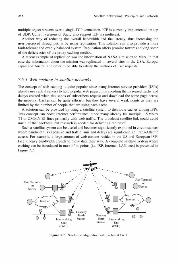
282 Satellite Networking: Principles and Protocols
multiple object streams over a single TCP connection. ICP is currently implemented on topof UDP. Current versions of Squid also support ICP via multicast.Another way of reducing the overall bandwidth and the latency, thus increasing the
user-perceived throughput, is by using replication. This solution can also provide a morefault-tolerant and evenly balanced system. Replication offers promise towards solving someof the deficiencies of the proxy caching method.A recent example of replication was the information of NASA’s mission to Mars. In that
case the information about the mission was replicated in several sites in the USA, Europe,Japan and Australia in order to be able to satisfy the millions of user requests.
7.6.5 Web caching in satellite networks
The concept of web caching is quite popular since many Internet service providers (ISPs)already use central servers to hold popular web pages, thus avoiding the increased traffic anddelays created when thousands of subscribers request and download the same page acrossthe network. Caches can be quite efficient but they have several weak points as they arelimited by the number of people that are using each cache.A solution can be provided by using a satellite system to distribute caches among ISPs.
This concept can boost Internet performance, since many already fill multiple 1.5Mbit/sT1 or 2Mbit/s E1 lines primarily with web traffic. The broadcast satellite link could avoidmuch of that backhaul, but research is needed for delivering the proof.Such a satellite system can be useful and becomes significantly exploited in circumstances
where bandwidth is expensive and traffic jams and delays are significant, i.e. trans-Atlanticaccess. For example, a large amount of web content resides in the US and European ISPsface a heavy bandwidth crunch to move data their way. A complete satellite system wherecaching can be introduced in most of its points (i.e. ISP, Internet, LAN, etc.) is presented inFigure 7.7.
Interworking Unit
(IWU)
Gateway Earth
Station
Internet
User Terminal or
Server
Internet
User Terminal or
Server
Interworking Unit
(IWU)
Gateway Earth
Station
Figure 7.7 Satellite configuration with caches at IWU

Impact of Satellite Networks on Transport Layer Protocols 283
7.7 Real-time transport protocol (RTP)
Originally the Internet protocols (e.g. TCP/IP) were primarily specified for the transmissionof raw data between computer systems. For a long time the TCP/IP protocol suite wasadequate for the transmission of still pictures and other row data-based documents. However,the emergence of modern applications and mainly those based on real-time voice and videopresent new requirements to the IP protocol suite. Though the former IP is not the idealprotocol for these suite of services, many applications appeared which present real-time (ornear real-time) characteristics using IP. Products are available that support streaming audio,streaming video and audio-video conferencing.
7.7.1 Basics of RTP
The real-time transport protocol (RTP) provides end-to-end network transport functionssuitable for applications transmitting real-time data, such as audio, video or simulation data,over multicast or unicast network services. RTP does not address resource reservation anddoes not guarantee QoS for real-time services. The data transport is augmented by a controlprotocol (RTCP), which allows monitoring of the data delivery in a manner scalable to largemulticast networks, and provides minimal control and identification functionality. RTP andRTCP are designed to be independent of the underlying transport and network layers.Applications typically run RTP on top of UDP to make use of its multiplexing and
checksum services. Figure 7.8 illustrates that the RTP is encapsulated into a UDP datagram,which is transported by an IP packet.Both RTP and RTCP protocols contribute parts of the transport protocol functionality.
There are two closely linked parts:
• The real-time transport protocol (RTP), to carry data that has real-time properties.• The RTP control protocol (RTCP), to monitor the quality of service and to conveyinformation about the participants in an ongoing session.
A defining property of real-time applications is the ability of one party to signal to oneor more other parties and initiate a call. Session invitation protocol (SIP) is a client-serverprotocol that enables peer users to establish a virtual connection (association) between themand then refers to a RTP (real-time transport protocol) (RFC1889) session carrying a singlemedia type. RTP provides end-to-end network transport functions suitable for applicationstransmitting real-time data, such as audio, video or simulation data, over multicast or unicastnetwork services. RTP does not address resource reservation and does not guarantee QoSfor real-time services.Note that RTP itself does not provide any mechanism to ensure timely delivery or provide
other QoS guarantees, but relies on lower layer services to do so. It does not guarantee
IP header RTP headerUDP header data
Figure 7.8 RTP packet encapsulations

284 Satellite Networking: Principles and Protocols
delivery or prevent out-of-order delivery, nor does it assume that the underlying network isreliable and delivers packets in sequence.There are four network components:
• End system: an application that generates the content to be sent in RTP packets and/orconsumes the content of received RTP packets.
• Mixer: an intermediate system that receives RTP packets from one or more sources,possibly changes the data format, combines the packets in some manner and then forwardsa new RTP packet.
• Translator: an intermediate system that forwards RTP packets with their synchronisationsource identifier intact. Examples of translators include devices that convert encodingswithout mixing, replications from multicast to unicast, and application-level filters infirewalls.
• Monitor: an application that receives RTCP packets sent by participants in an RTPsession, in particular the reception reports, and estimates the current QoS for distributionmonitoring, fault diagnosis and long-term statistics.
Figure 7.9 shows the RTP header format. The first 12 octets are present in every RTPpacket, while the list of contribution source (CSRC) identifiers is present only when insertedby a mixer. The fields have the following meaning:
• Version (V): two bits – this field identifies the version of RTP. The current version is two(2). (The value 1 is used by the first draft version of RTP and the value 0 is used by theprotocol initially implemented in the ‘vat’ audio tool.)
• Padding (P): one bit – if the padding bit is set, the packet contains one or more additionalpadding octets at the end which are not part of the payload. The last octet of the padding
V P X M
3116 0
addedby mixer
C
SSRC
PT sequence number
CSRC
timestamp
V 2-bits, version number (=2)P 1-bit, indicates paddingX 1-bit, indicates extension header presentCC 4-bits, number of CSRCs (CSRC count)M 1-bit, profile specific marker (defined elsewhere) PT 7-bits, payload type, profile specific (defined elsewhere)SSRC synchronisation sourceCSRC contributing source Timestamp has profile / flow-specific units
Figure 7.9 RTP header information

Impact of Satellite Networks on Transport Layer Protocols 285
contains a count of how many padding octets should be ignored, including last paddingoctet.
• Extension (X): one bit – if the extension bit is set, the fixed header must be followed byexactly one header extension, with a defined format.
• Contribution source (CSRC) count (CC): four bits – the CSRC count contains the numberof CSRC identifiers that follow the fixed header.
• Marker (M): one bit – the interpretation of the marker is defined by a profile.• Payload type (PT): seven bits – this field identifies the format of the RTP payload anddetermines its interpretation by the application. A set of default mappings for audio andvideo is specified in the companion RFC1890.
• Sequence number: 16 bits – the sequence number increments by one for each RTP datapacket sent, and may be used by the receiver to detect packet loss and to restore packetsequence.
• Timestamp: 32 bits – the timestamp reflects the sampling instant of the first octet in theRTP data packet. The sampling instant must be derived from a clock that incrementsmonotonically and linearly in time to allow synchronisation and jitter calculations.
• Synchronisation source (SSRC): 32 bits – the SSRC field identifies the synchronisationsource. This identifier should be chosen randomly, with the intent that no two synchroni-sation sources within the same RTP session will have the same SSRC identifier.
• CSRC list: 0 to 15 items, 32 bits each – the CSRC list identifies the contributing sourcesfor the payload contained in this packet. The number of identifiers is given by the CCfield. If there are more than 15 contributing sources, only 15 can be identified.
7.7.2 RTP control protocol (RTCP)
The RTP control protocol (RTCP) is based on the periodic transmission of control packetsto all participants in the session, using the same distribution mechanism as the data packets.The underlying protocol must provide multiplexing of the data and control packets, forexample using separate port numbers with UDP. RTCP performs four functions:
• The primary function is to provide feedback on the quality of the data distribution.This is an integral part of the RTP role as a transport protocol and is related to theflow and congestion control functions of other transport protocols. The feedback may bedirectly useful for control of adaptive encodings, but experiments with IP multicastinghave shown that it is also critical to get feedback from the receivers to diagnose faultsin the distribution. Sending reception feedback reports to all participants allows whoeveris observing problems to evaluate whether those problems are local or global. With adistribution mechanism like IP multicast, it is also possible for an entity such as a networkservice provider who is not otherwise involved in the session to receive the feedbackinformation and act as a third-party monitor to diagnose network problems. This feedbackfunction is performed by the RTCP sender and receiver reports (RS and RR) – seeFigure 7.10.
• RTCP carries a persistent transport-level identifier for an RTP source called the canonicalname or CNAME. Since the SSRC identifier may change if a conflict is discovered ora program is restarted, receivers require the CNAME to keep track of each participant.Receivers may also require the CNAME to associate multiple data streams from a given

286 Satellite Networking: Principles and Protocols
V P 31 16 0
RC
NTP timestamp, hi-word
PT= length
NTP timestamp, lo-word
SSRC of sender
RTP timestamp
sender’s packet count
sender’s octet count
cum. no. of pkts lost
ext. highest seq. n. recv’d
inter-arrival jitter
frac.
SSRC1 (SSRC of source 1)
last SR NTP timestamp (part)
delay since last SR
multiple instances of this report block possible in asingle report
V P 31 160
RC PT= length
SSRC of sender
cum. no. of pkts lost
ext. highest seq. n. recv’d
inter-arrival jitter
frac.
SSRC1 (SSRC of source 1)
last SR NTP timestamp (part)
delay since last SR
Header
Sender information
Figure 7.10 Sender report (SR) and receiver report (RR)
participant in a set of related RTP sessions, for example to synchronise audio and video.Inter-media synchronisation also requires the NTP and RTP timestamps included in RTCPpackets by data senders.
• The first two functions require that all participants send RTCP packets, therefore the ratemust be controlled in order for RTP to scale up to a large number of participants. Byhaving each participant send its control packets to all the others, each can independentlyobserve the number of participants.
• A fourth, optional function is to convey minimal session control information, for exampleparticipant identification to be displayed in the user interface. This is most likely tobe useful in ‘loosely controlled’ sessions where participants enter and leave withoutmembership control or parameter negotiation.
7.7.3 Sender report (SR) packets
There are three sections. The first section (header) consists of the following fields:
• Version (V): two bits – identifies the version of RTP, which is the same in RTCP packetsas in RTP data packets. The current version is two (2).
• Padding (P): one bit – if the padding bit is set, this individual RTCP packet contains someadditional padding octets at the end which are not part of the control information but areincluded in the length field. The last octet of the padding is a count of how many paddingoctets should be ignored, including itself (it will be a multiple of four).
• Reception report count (RC): five bits – the number of report blocks contained in thispacket.
• Packet type (PT): eight bits – contains the constant 200 to identify this as an RTCP SRpacket.

Impact of Satellite Networks on Transport Layer Protocols 287
• Length: 16 bits – the length of this RTCP packet in 32-bit words minus one, includingthe header and any padding.
• SSRC: 32 bits – the synchronisation source identifier for the originator of this SR packet.
The second section, the sender information, is 20 octets long and is present in everysender report packet. It summarises the data transmissions from this sender. The fields havethe following meaning:
• NTP timestamp: 64 bits – indicates the wall clock time when this report was sent so thatit may be used in combination with timestamps returned in reception reports from otherreceivers to measure round-trip propagation to those receivers.
• RTP timestamp: 32 bits – corresponds to the same time as the NTP timestamp (above), but inthe same units and with the same random offset as the RTP timestamps in data packets.
• Sender’s packet count: 32 bits – the total number of RTP data packets transmitted by thesender since starting transmission up until the time this SR packet was generated.
• Sender’s octet count: 32 bits – the total number of payload octets (i.e., not including headeror padding) transmitted in RTP data packets by the sender since starting transmission upuntil the time this SR packet was generated.
The third section contains zero or more reception report blocks depending on the numberof other sources heard by this sender since the last report. Each reception report blockconveys statistics on the reception of RTP packets from a single synchronisation source.SSRC_n (source identifier): 32 bits – the SSRC identifier of the source to which the
information in this reception report block pertains, including:
• Fraction lost: eight bits – the fraction of RTP data packets from source SSRC_n lost sincethe previous SR or RR packet was sent, expressed as a fixed point number with the binarypoint at the left edge of the field. This fraction is defined to be the number of packets lostdivided by the number of packets expected.
• Cumulative number of packets lost: 24 bits – the total number of RTP data packets fromsource SSRC_n that have been lost since the beginning of reception. This number isdefined to be the number of packets expected less the number of packets actually received.
• Extended highest sequence number received: 32 bits – the least significant 16 bits containthe highest sequence number received in an RTP data packet from source SSRC_n, andthe most significant 16 bits extend that sequence number with the corresponding count ofsequence number cycles.
• Inter-arrival jitter: 32 bits – an estimate of the statistical variance of the RTP datapacket inter-arrival time, measured in timestamp units and expressed as an unsignedinteger. The inter-arrival jitter J is defined to be the mean deviation (smoothed absolutevalue) of the difference D in packet spacing at the receiver compared to the sender fora pair of packets.
• Last SR timestamp (LSR): 32 bits – the middle 32 bits out of 64 in the NTP timestampreceived as part of the most recent RTCP sender report (SR) packet from source SSRC_n.If no SR has been received yet, the field is set to zero.
• Delay since last SR (DLSR): 32 bits – the delay, expressed in units of 1/65536 seconds,between receiving the last SR packet from source SSRC_n and sending this reception reportblock. If no SR packet has been received yet from SSRC_n, the DLSR field is set to zero.

288 Satellite Networking: Principles and Protocols
7.7.4 Receiver report (RR) packets
The format of the receiver report (RR) packet is the same as that of the SR packet exceptthat the packet type field contains the constant 201 and the five words of sender informationare omitted. The remaining fields have the same meaning as for the SR packet.
7.7.5 Source description (SDES) RTCP packet
The SDES packet is a three-level structure composed of a header and zero or more chunks,each of which is composed of items describing the source identified in that chunk. Eachchunk consists of an SSRC/CSRC identifier followed by a list of zero or more items, whichcarry information about the SSRC/CSRC. Each chunk starts on a 32-bit boundary. Eachitem consists of an eight-bit type field, an eight-bit octet count describing the length of thetext (thus, not including this two-octet header), and the text itself. Note that the text canbe no longer than 255 octets, but this is consistent with the need to limit RTCP bandwidthconsumption.End systems send one SDES packet containing their own source identifier (the same as
the SSRC in the fixed RTP header). A mixer sends one SDES packet containing a chunk foreach contributing source from which it is receiving SDES information, or multiple completeSDES packets if there are more than 31 such sources.The SDES items currently defined include:
• CNAME: canonical identifier (mandatory);• NAME: name of user;• EMAIL: address user;• PHONE: number for user;• LOC: location of user, application specific;• TOOL: name of application/tool;• NOTE: transient messages from user;• PRIV: application specific/experimental use.
Goodbye RTCP packet (BYE): the BYE packet indicates that one or more sources are nolonger active.Application-defined RTCP packet (APP): the APP packet is intended for experimental
use as new applications and new features are developed, without requiring packet type valueregistration.
7.7.6 SAP and SIP protocols for session initiations
There are several complementary mechanisms for initiating sessions, depending on thepurpose of the session, but they essentially can be divided into invitation and announcementmechanisms. A traditional example of an invitation mechanism would be making a telephonecall, which is essentially an invitation to participate in a private session. A traditional exampleof an announcement mechanism is the television guide in a newspaper, which announcesthe time and channel that each programme is broadcast. In the Internet, in addition to these

Impact of Satellite Networks on Transport Layer Protocols 289
two extremes, there are also sessions that fall in the middle, such as an invitation to listento a public session, and announcements of private sessions to restricted groups.The session announcement protocol (SAP) must be one of the simplest protocols around.
To announce a multicast session, the session creator merely multicasts packets periodicallyto a well-known multicast group carrying an SDP description of the session that is going totake place. People that wish to know which sessions are going to be active simply listen tothe same well-known multicast group, and receive those announcement packets. Of course,the protocol gets a little more complex when we take security and caching into account, butbasically that’s it.The session initiation protocol (SIP) works like making a telephone call, e.g. finds the
person you’re trying to reach and causes their phone to ring. The most important way thatSIP differs from making an existing telephone call (apart from that it is an IP-based protocol)is that you may not be dialling a number at all. Although SIP can call traditional telephonenumbers, SIP native concept of an address is an SIP URL, which looks very like an emailaddress. Figure 7.11 illustrates a typical SIP call of an initiate and terminate session.Users may move to a different location. Redirect servers and location servers can be used
to assist SIP calls. Figure 7.12 illustrates a typical SIP call using redirect server and locationserver.
User Agent Client
(UAC)
Invite
User Agent Server (UAS)
Trying
Ringing
Info: 2 caller ahead
ACK
BYE
OK
Info: 1 caller ahead
OK
Figure 7.11 A typical SIP call of initiate and terminate session
UserAgentClient(UAC) User
AgentServer(UAS)
RedirectServer
LocationServer
1. Invite
4. Return new address
5. ACK
2. Invite
3. Return new address
6. Invite
7. OK
8. ACK
Figure 7.12 A typical SIP call using a redirect server and location server

290 Satellite Networking: Principles and Protocols
UserAgentClient(UAC)
1. Invite
UserAgentServer(UAS)
2. Trying
8. Ringing
11. ACK
Proxy Server
3. Invite
4. Return new address
LocationServer
5. Invite
6. Trying
7. Ringing
9. OK10. OK
Figure 7.13 A typical SIP call using a proxy server and location server
SIP makes extensive use of proxy servers, each of which looks at the call request, looksup whatever local information it has about the person being called (i.e., the callee), performsany security checks it has been asked by the callee or her organisation to make, and thenroutes the call onward. Figure 7.13 shows a typical SIP call using a proxy server and locationserver.There are two multicast channels per application per session: one for RTCP and the
other for RTCP. It allows ad hoc configurations as stand-alone for individual applica-tions; and also allows advertised conference with session directory (SDR) and configurationinformation.
7.7.7 Session directory service (SDS)
The growth in multicast services and applications has led to some navigation difficulties(just as there are in the WWW). This has led to the creation of a session directory service(SDS). This has several functions:
• A user creating a conference needs to choose a multicast address that is not in use. Thesession directory system has two ways of doing this: firstly, it allocates addresses using apseudo-random strategy based on how widespread the conference is going to be accordingto the user, and where the creator is; secondly, it multicasts the session information out,and if it detects a clash from an existing session announcement, it changes its allocation.This is currently the main mechanism for the management of allocation and listing ofdynamic multicast addresses.
• Users need to know what conferences there are on the multicast backbone (Mbone), whatmulticast addresses they are using, and what media are in use on them. They can use thesession directory messages to discover all of this. The latest versions of multicast includea facility for administrative scoping, which allows session creators to designate a logicalregion of interest outside of which traffic will not (necessarily) flow.
• Furthermore, the session directory tools currently implemented will launch applicationsfor the user.

Impact of Satellite Networks on Transport Layer Protocols 291
7.8 Voice over IP
Based on RTP, IP telephony is becoming a mainstream application moving away fromproprietary solutions to standards based solutions, providing QoS comparable to the PSTN,and providing transparent interoperability of the IP and PSTN networks.
7.8.1 Gateway decomposition
The signalling gateway is responsible for signalling between end users on either network.On the PSTN side, SS7 or ISDN (T1/E1-BRI/PRI) is used, which is then translated to anIP signalling protocol such as SIP or H.323, and transported across the IP network. SAP isused to announce the session. SDP is used to describe the call (or session).Once a call is set up, the media gateway is responsible for transfer of the data, video
and audio streams. On the PSTN side, media transport is by PCM-encoded data on TDMstreams; on the IP network side, on RTP/UDP. The media gateway controller is used tocontrol one or more media gateways.
7.8.2 Protocols
VoIP uses a number of protocols. As far back as 1994, the ITU introduced its H.323 family ofprotocols, to provide multimedia capability over the Internet. Many vendors have developedand deployed these solutions. In parallel, the IETF introduced many protocols used forIP telephony – RTP, RTSP, RTCP, Megaco, SIP, and SDP. These protocols provide thefoundation for standards based IP telephony.
7.8.3 Gatekeepers
Gatekeepers are responsible for addressing, authorisation and authentication of terminaland gateways, bandwidth management, accounting, billing and charging. They may alsoprovide call-routing services. Terminal is a PC or stand-alone device running multimediaapplications. Multipoint control units (MCU) provide support for conferences of three ormore terminals.
7.8.4 Multimedia conferencing (MMC)
Multimedia conferencing (MMC) is one of the typical example applications based on IPmulticast. It is also well suited for satellite networks with great advantages. It consists ofmultimedia application with the following components:
• Voice provides packet audio in time slices, numerous audio-coding schemes, redundantaudio for repair, unicast or multicast, configurable data rates.
• Video provides packet video in frames, numerous video-coding schemes, unicast or mul-ticast, configurable data rates.
• Network Text Editor can be used for message exchanges• Whiteboard can be used for free-hand drawing.

292 Satellite Networking: Principles and Protocols
It should allow local scoped groups, global scope groups and administratively scopedgroups, and also unicast traffic gateway (UTG) so that routers routing protocols and multicastdomains can be reached by tunnelling, i.e., in a LAN, IP packets are multicasted to all hostsdirectly; and in a WAN it is a virtual overlay network on top of the Internet. RTP/RTCPis used as the protocol for transmission and control. Overlapping multicast domains can beconfigured by using different administratively scoped addresses in each of the domains.
7.8.5 Conference control
Conference control provides functions and mechanisms for users to control how to organise,manage and control a conference, with the following control functions:
• Floor control: who speaks? chairman control? distributed control?• Loose control: one person speaks, grabs channel.• Strict control: application specific, e.g. lecture.• Resource reservation: bandwidth requirement and quality of the conference.• Per-flow reservation: audio only, video only, audio and video.
Further reading[1] Allman, M., Floyd, S. and C. Partridge, Increasing TCP’s Initial Window, RFC 2414, September 1998.[2] Allman, M., Glover, D. and L. Sanchez, Enhancing TCP over Satellite Channels using Standard Mechanisms,
BCP 28, RFC 2488, January 1999.[3] Allman, M., Paxson, V. and W. Richard Stevens, TCP Congestion Control, RFC 2581, April 1999.[4] Braden, R., Transaction TCP – Concepts, RFC 1379, September 1992.[5] Braden, R., T/TCP – TCP Extensions for Transactions: Functional Specification, RFC 1644, July 1994.[6] Chotikapong, Y., TCP/IP and ATM over LEO satellite networks, PhD thesis, University of Surrey, 2000.[7] Chotikapong, Y., Cruickshank, H. and Z. Sun, ‘Evaluation of TCP and Internet traffic via low earth orbit
satellites, IEEE Personal Communications over Satellites, Special Issue on Multimedia Communications overSatellites, 8(3): 28–34, 2001.
[8] Chotikapong, Y. and Z. Sun, Evaluation of application performance for TCP/IP via satellite links, IEEColloquium on Satellite Services and the Internet, 17 February 2000.
[9] Chotikapong, Y., Sun, Z., Örs, T. and B.G. Evans, Network architecture and performance evaluation of TCP/IPand ATM over satellite, 18th AIAA International Communication Satellite Systems Conference and Exhibit,Oakland, April 2000.
[10] Jacobson, V., Compressing TCP/IP Headers, RFC 1144, February 1990.[11] Mathis, M., Mahdavi, J., Floyd, S. and A. Romanow, TCP Selective Acknowledgment Options, RFC 2018,
October 1996.[12] Paxson, V., Allman, M., Dawson, S., Heavens, I. and B. Volz, Known TCP Implementation Problems, RFC
2525, March 1999.[13] Ramakrishnan, K. and S. Floyd, A Proposal to Add Explicit Congestion Notification (ECN) to IP, RFC 2481,
January 1999.[14] Stevens, W., TCP Slow Start, Congestion Avoidance, Fast Retransmit, and Fast Recovery Algorithms, RFC
2001, January 1997.[15] Sun, Z., TCP/IP over satellite, in Service Efficient Network Interconnection via Satellite, Fun Hu, Y., Maral, G.
and Erina Ferro (eds), John Wiley & Son, Inc., pp. 195–212.[16] Sun, Z., Chotikapong, Y. and C. Chaisompong, Simulation studies of TCP/IP performance over satellite, 18th
AIAA International Communication Satellite Systems Conference and Exhibit, Oakland, April 2000.[17] Sun, Z. and H. Cruickshank, Analysis of IP voice conferencing over geostationary satellite systems, IEE
Colloquium on Satellite Services and the Internet, 17 February 2000.

Impact of Satellite Networks on Transport Layer Protocols 293
[18] RFC 793, Transmission control protocol, Jon Postel, IETF, September 1981.[19] RFC 1122, Requirements for Internet Hosts – Communication Layers, R. Braden, IETF, October 1989.[20] RFC 1323, TCP Extensions for High Performance, V. Jacobson, R. Braden and D. Borman, IETF, May 1992.[21] RFC 2142, Mailbox names for common services, roles and functions, D. Crocker, IETF, May 1997.[22] RFC 1889, RTP: A Transport Protocol for Real-Time Applications, H. Schulzrinne, S. Casner, R. Frederick
and V. Jacobson, IETF, January 1996.[23] RFC 1890, RTP Profile for Audio and Video Conferences with Minimal Control, H. Schulzrinne, IETF,
January 1996.
Exercises
1. Explain how satellite networks affect the performance of TCP due to flow control,error controls and congestion control mechanisms.
2. Discuss typical satellite network configurations for the Internet connections.3. Explain TCP enhancement for satellite networks based on the slow-start algorithm.4. Explain TCP enhancement based on the congestion avoidance mechanism.5. Discuss how to achieve TCP enhancement based on acknowledgement.6. Calculate the utilisation of satellite bandwidth in the slow-start and congestion
avoidance stages.7. Explain TCP enhancement on error recovery mechanisms including fast retrans-
mission and fast recovery.8. Explain the pros and cons of TCP spoofing and split TCP (also known as cascading
TCP) mechanisms.9. Explain the limitation of TCP enhancement mechanisms based on existing TCP
mechanisms.10. Discuss the real-time protocols including RTP, RTCP, SAP, SIP, etc., and the
HTTP protocol.11. Compare differences between non-real-time applications, WWW and FTP, and
real-time applications, VoIP and MMC.


8Next Generation Internet (NGI)over Satellite
This chapter aims to introduce next generation Internet (NGI) over satellite. We try notto separate satellites from general networks, as satellites are considered as an integratedpart of the Internet. First this chapter introduces new services and applications, modellingand traffic engineering and multi-protocol label switching (MPLS), then it introduces theInternet protocol version 6 (IPv6) including addressing and transitions, and particularly itexplains IPv6 over satellite including tunnelling and translation techniques of IPv6 oversatellite networks. Finally, as a conclusion, it discusses the future development of satellitenetworking. When you have completed this chapter, you should be able to:
• Understand the concepts of new services and applications to be supported in future satellitenetworks.
• Understand the basic principles and techniques for traffic modelling and traffic character-isation.
• Understand the nature of Internet traffic.• Describe the concepts of traffic engineering in general and Internet traffic engineering inparticular.
• Appreciate the principles of MPLS, and interworking with different technologies andtraffic engineering concepts.
• Understand IPv6 and its main differences from IPv4.• Understand IPv6 addressing and transition techniques.• Understand IPv6 over satellite networks and transition techniques such as tunnelling andtranslations.
• Appreciate the future development and convergence of satellite networking.
Satellite Networking: Principles and Protocols Zhili Sun© 2005 John Wiley & Sons, Ltd

296 Satellite Networking: Principles and Protocols
8.1 Introduction
In recent years, we have seen the tremendous spread of mobile networks. The new generationsof mobile telephones have become more and more sophisticated, with increasing capabilitiesof email, WWW access, multimedia messaging, streaming voice and video broadcasting,which go far beyond the original definition of mobile phones.In terms of software, the mobile phone is more like a computer than a telephone. There are
full Internet protocol stacks (TCP/IP), transmission technologies (infrared,wireless,USB, etc.),and various peripheral devices. In computer networks, Ethernet and wireless LANs dominateLANs. In mobile networks, the GSM mobile networks are evolving towards 3G networks.They are converging towards an all-IP solution. The Internet protocol (IP) has also evolvedto cope with demands from networking technologies and new services and applications.Inevitably, satellite networking is also evolving towards an all-IP solution and is following
the trends in the terrestrialmobile and fixed networks. In addition to user terminals, services andapplications are also converging, i.e., satellite network terminals aim to be the same as terrestrialnetwork terminals providing the same user interface and functionality. As the current satellitenetworks integrate with terrestrial networks, it is not difficult to see that future satelliteterminals will be fully compatible with standard terrestrial network terminals, but with adifferent air interface in the lower layers of the protocol stack (physical and link layers only).In traditional computer networks, network designers were not very concerned with QoS,
traffic engineering and security. For real-time services, QoS and traffic engineering areimportant and have been successfully implemented in telephony networks for nearly a cen-tury. More and more people own portable computers and mobility is now a new requirement.More and more business transactions, commercial and public uses of the Internet makesecurity a very important Internet issue.The original design of the Internet did not take all these new requirements and the large
scale of today’s Internet into consideration. There is also concern that IPv4 may soon runout of IP addresses. Although IPv6 has started to address these issues, we are still a longway from a perfect solution.So far, we have completed our discussion about the transition from physical layer to trans-
port layer. Now it is time to discuss new services and applications (starting from informationprocessing) and the development of satellite networks and related issues, including trafficmodelling and characterisation, MPLS, traffic engineering and IPv6.
8.2 New services and applications
We have discussed various kinds of network services which we expect to support oversatellite networks. The services information has to be encoded in proper formats to be suitablefor transmission, and decoded at the receiver. The new services and applications shouldinclude major components of high-quality digital voice, image and video (and combinationsof these) across broadband networks. Here we briefly discuss some of these topics.
8.2.1 Internet integrated services
One of the principal functions of network layer protocols is to offer universal connectivity,and a uniform service interface, to higher layer protocols – in particular, to transport layer

Next Generation Internet (NGI) over Satellite 297
protocols – independent of the nature of the underlying physical network. Correspondingly,the function of transport layer protocols is to provide session control services (e.g. reliability)to applications, without being tied to particular networking technologies.Unless applications run over common network and transport protocols, interoperability
for the same applications running on different networks would be difficult, if not impossible.Most multimedia applications will continue to build upon enhancements of current Internetprotocols, and deploy a wide variety of high-speed Internet networking technologies.In the specific case of IP, the IETF has developed the notion of an integrated services
Internet. This envisages a set of enhancements to IP to allow it to support integratedor multimedia services. These enhancements include traffic management mechanisms thatclosely match the traffic management mechanisms of telecommunication networks.Network protocols rely upon a flow specification to characterise the expected traffic
patterns for streams of IP packets, which the network can process through packet-levelpolicing, shaping and scheduling mechanisms to deliver a requested QoS. In other words,a flow is a layer-three connection, since it identifies and characterises a stream of packets,even though the protocol remains connectionless.
8.2.2 Elastic and inelastic traffic
There are two main classifications of Internet traffic generated by services and applications:
• Elastic traffic: this type of traffic is essentially based on TCP, i.e., it uses TCP as thetransport protocol. Elastic traffic is defined as traffic that is capable of adapting its flowrate according to changes in delay and throughput across the network. This capabilityis built-in to the TCP flow control mechanisms. This type of traffic is also known asopportunistic traffic, i.e., if resources are made available, these applications would try toconsume them; on the other hand if the resources are temporarily unavailable they canwait (withholding transmission) without adversely affecting the applications. Examples ofelastic traffic include email, file transfers, network news, interactive applications such asremote login (telnet) and web access (HTTP). These applications can cope well with delayand variable throughput in the network. This type of traffic can be further categorised intolong-lived and short-lived responsive flows, depending on the length of time the flowsare active. FTP is an example of a long-lived responsive flow while HTTP represents ashort-lived flow.
• Inelastic traffic: this type of traffic is essentially based on UDP, i.e., it uses UDP as thetransport protocol. Inelastic traffic is exactly the opposite of elastic traffic – the trafficis incapable of varying its flow rate when faced with changes in delay and throughputacross the network. A minimum amount of resources is required to ensure the applicationworks well; otherwise, the applications will not perform adequately. Examples of inelastictraffic include conversational multimedia applications such as voice or video over IP,interactive multimedia applications such as network games or distributed simulationsand non-interactive multimedia applications such as distance learning or audio/videobroadcasts where a continuous stream of multimedia information is involved. These real-time applications can cope with small delays but cannot tolerate jitter (variations in averagedelay). This stream traffic is also known as long-lived non-responsive flow.

298 Satellite Networking: Principles and Protocols
In terms of applications, at present the Internet carries computer data traffic almostexclusively. Traditionally these have been applications such as file transfer (using the FTPprotocol), remote login sessions (telnet) and email (SMTP). However, these applicationshave been somewhat overshadowed by the World Wide Web (HTTP). Voice over IP andvideo and audio streaming over IP applications are only emerging and are not yet con-tributing significantly to the composition of Internet traffic. However, they are expected tobe the major bandwidth consumers in the future. While the protocol composition remainsroughly the same in proportion, UDP applications are expected to have an increase in theRTP/RTCP portion. This is due to increases in audio/video streaming and online gamingapplications.
8.2.3 QoS provision and network performance
As defined in the QoS architecture, best-effort service is the default service that a networkgives to a datagram between the source and destination in today’s Internet networks. Amongother implications, this means that if a datagram changes to a best-effort datagram, all flowcontrols that apply normally to a best-effort datagram also apply to the datagram.The controlled load service is intended to support a broad class of applications in the
Internet, but is highly sensitive to overloaded conditions. Important members of this classare the ‘adaptive real-time applications’ currently offered by a number of vendors andresearchers. These applications work well on networks with light load conditions, but degradequickly with overload conditions. A service, which mimics an unloaded network, servesthese applications well.Guaranteed service means that a datagram will arrive within a limited time with limited
packet loss ratio, if the flow’s traffic stays within its specified traffic parameters. Thisservice is intended for applications requiring a firm guarantee of delay within a certain timelimit for the traffic to reach its destination. For example, some audio and video ‘playback’applications are intolerant of any datagram arriving after their playback time. Applicationsthat have hard real-time requirements also require guaranteed service.In playback applications, datagrams often arrive far earlier than the delivery deadline and
have to be buffered at the receiving system until it is time for the application to processthem.
8.3 Traffic modelling and characterisation
Future network infrastructures will have to handle a huge amount of IP traffic from differenttypes of services, including a significant portion of real-time services. The multi-servicecharacteristics of such a network infrastructure demand a clear requisite: the ability tosupport different classes of services with different QoS requirements. Moreover, Internettraffic is more variable with time and bandwidth, with respect to traditional traffic intelecommunication networks, and it is not easily predictable. This means that networks haveto be flexible enough to react adequately to traffic changes. Besides the requirements offlexibility and multi-service capabilities that lead to different levels of QoS requirements,there is also a need to reduce complexity.

Next Generation Internet (NGI) over Satellite 299
8.3.1 Traffic modelling techniques
Multi-services networks need to support a varied set of applications. These applicationscontain either one or (more often than one) a combination of the following components:data, audio and video. More widely termed as multimedia applications, these components,together with the applications’ requirements, will generate a heterogeneous mixture of trafficwith different statistical and temporal characteristics. These applications and services requireresources to perform their functions. Of special interest is resource sharing among application,system and network. Traffic engineering is a network function that controls a network’sresponse to traffic demands and other stimuli (such as failures) and encompasses trafficand capacity/resource management. In order for the multi-services networks to efficientlysupport these applications, while at the same time optimally utilises the networks’ resources,traffic engineering mechanisms need to be devised. These mechanisms relate intrinsically tothe characteristics of the traffic getting into the network. To devise efficient resource andtraffic management schemes requires an understanding of the source traffic characteristicsand the development of appropriate traffic models. Hence, source traffic characterisation andmodelling is a crucial first step in the overall network design and performance evaluationprocess. Indeed traffic modelling is identified as one of the key subcomponents of the trafficengineering process model.
8.3.2 Scope of traffic modelling
Traffic characterisation describes what traffic patterns the application/user generates. Thegoal is to develop an understanding of the nature of the traffic and to devise tractable modelsthat capture the important properties of the data, which can eventually lead to accurateperformance prediction. Tractability is an important feature as it infers that the traffic modelsused in subsequent analysis readily lend themselves to numerical computation, simulationand analytical solutions. They also have wide range of time scales.Traffic modelling summarises the expected behaviour of an application or an aggregate
of applications. Among the primary uses of traffic characteristics are:
• Long-range planning activities (network planning, design and capacity management).• Performance prediction, real-time traffic control/management and network control.
Traffic models can be utilised in three different applications:
• As a source for generating synthetic traffic to evaluate network protocols and designs.This complements the theoretical part of the analysis, which increases in complexity asnetworks become complicated.
• As traffic descriptors for a range of traffic and network resource management functions.These include call admission control (CAC), usage parameter control (UPC) and trafficpolicing. These functions are the key to ensure meeting certain network QoS levels whileachieving high multiplexing gains.
• As source models for queuing analysis, they use queuing systems extensively as theprimary method for evaluating network performances and as a tool in network design.A reasonably good match to real network traffic will make analytical results more usefulin practical situations.

300 Satellite Networking: Principles and Protocols
8.3.3 Statistical methods for traffic modelling
The main aim of traffic modelling is to map accurately the statistical characteristics of actualtraffic to a stochastic process from which synthetic traffic can be gemerated.For a given traffic trace (TT), the model finds a stochastic process (SP) defined by a small
number of parameters such that:
• TT and SP give the same performance when fed into a single server queue (SSQ) for anybuffer size and service rate.
• TT and SP have the same mean and autocorrelation (goodness-of-fit).• Preferably, SP SSQ is amenable to analysis.
There are many traffic models that have been developed over the years.
8.3.4 Renewal traffic models
A renewal process is defined as a discrete-time stochastic process, Xt, where Xt areindependent identically distributed (iid), non-negative random variables with a general dis-tribution function. Independence here implies that observation at time t does not depend onthe past or future observation, i.e., there is no correlation between the present observationand previous observations.Analysing renewal processes is mathematically simple. However, there is one major
shortcoming with this model: the absence of an autocorrelation function. Autocorrelationis a measure of the relationship between two time instances of a stochastic process. It isan important parameter and is used to capture the temporal dependency and burst of thetraffic. As mentioned previously, temporal dependencies are important in a multimedia trafficstream while burst traffic expect to dominate broadband networks. Therefore, models, whichcapture the autocorrelated nature of traffic, are essential for evaluating the performance ofthese networks.However, because of its simplicity, the renewal process model is still widely used to
model traffic sources. Examples of a renewal process include the Poisson and Bernoulliprocesses.
8.3.5 Markov models
The Poisson and Bernoulli processes display memory-less properties in the sense that thefuture does not depend on the past, i.e., the occurrences of new arrivals do not depend onthe history of the process. This in turn results in the non-existence of the autocorrelationfunction since there is no dependency among the random sequence of events.Markov-based traffic models overcome this shortcoming by introducing dependency into
the random sequence. Consequently, autocorrelation is now non-zero and this can capturethe characteristics of traffic burst. Markov dependency or a Markov process is definedas a stochastic process Xt where for any t0 < · · · < tn < tn+1 and given the values ofXt0 Xtn, the distribution of Xtn+1 only depends on Xtn. This implies that thenext state in a Markov stochastic process only depends on the current state of the process

Next Generation Internet (NGI) over Satellite 301
and not on states assumed previously; this is the minimum possible dependence that canexist between successive states. How the process arrives at the current state is irrelevant.Another important implication of this Markov property is that the next state only depends
on the current state and not on how long the process has already been in that (current)state. This means that the state residence times (also called sojourn times) must be randomvariables with memory-less distribution. Examples of Markov models include on-off andMarkov modulated Poisson process (MMPP).
8.3.6 Fluid traffic models
Fluid traffic models view traffic as a stream of fluid characterised by a flow rate (e.g.,bits per second), that traffic volume is better than traffic count in the model. Fluid modelsare based on the assumption that the number of individual traffic units (packets or cells)generated during the active period is so large that it appears like a continuous flow of fluid.In other words, a single unit of traffic in this case would have little significance and itsimpact on the overall flow is negligible, i.e., individual units will only add infinitesimalinformation to the traffic stream.An important benefit of the fluid traffic model is that it can achieve enormous savings in
computing resources when simulating streams of traffic as described above. For example,in an ATM network scenario supporting the transmission of high-quality video, it requiresa large number of ATM cells for a compressed video at 30 frames per second. If a modelwere to distinguish between cells and consider the arrival of each ATM cell as a separateevent, processing cell arrivals would quickly consume vast amounts of CPU and memory,even if the simulated time were in the order of a few minutes.By assuming the incoming fluid flow remains (roughly) constant over much longer periods,
a fluid flow simulation performs well. A change in flow rate signals the event that traffic isfluctuating. Because these changes can occur far less frequently than the arrival of individualcells the computing overhead involved is greatly reduced.
8.3.7 Auto-regressive and moving average traffic models
Auto-regressive traffic models define the next random variable in the sequence Xn as anexplicit function of previous variables within a time window stretching from present to past.Some of the popular auto-regressive models are:
• Linear auto-regressive processes, AR(p), described as
Xn = a0+p∑
r=1
arXn−r +n n > 0
where Xn are the family of random variables, ar0≤ r ≤ p are real constants and n arezero-mean, uncorrelated random variables also called white noise, which are independentof Xn.

302 Satellite Networking: Principles and Protocols
• Moving average processes, MA(q), described as
Xn =q∑
r=0
brn−r n > 0
• Auto-regressive moving average processes, ARMA (p, q), described as
Xn = a0+p∑
r=1
arXn−r +q∑
r=0
brn−r
8.3.8 Self-similar traffic models
The development of these models were based on the observation that Internet traffic dynamicsresulting from interactions among users, applications and protocols, is best represented bythe notion of ‘fractals’ a well-established theories with wide applications in physics, biologyand image processing. Therefore, it is natural to apply traffic models that are inherentlyfractal for characterisation of Internet traffic dynamics and generating synthesised traffic ina computationally efficient manner.Wavelet modelling offers a powerful and flexible technique for mathematically represent-
ing network traffic at multiple time scales. A wavelet is a mathematical function havingprinciples similar to that of Fourier analysis; it is widely used in digital signal processingand image compression techniques.
8.4 The nature of internet traffic
Internet traffic is due to a very large pool of uncoordinated, i.e. independent users access-ing and using the various applications. Each Internet communication consists of a transferof information from one computer to another for e.g. downloading web pages or send-ing/receiving emails. Packets containing bits of information transmitted over the Internet arethe result of simultaneous active communications between two or more computers (usuallytermed as hosts) on the Internet.
8.4.1 The world wide web (WWW)
A web page typically consists of multiple elements or objects when downloaded. Theseobjects are loaded using separate HTTP GET requests, serialised in one or more parallelTCP connections to the corresponding server(s). In practice, web access is request–responseoriented with bursts of numerous requests and small, unidirectional responses. Retrieval ofa complete web page requires separate requests for text and each embedded image, thusmaking traffic inherently burst. Figure 8.1 illustrates a typical message sequence in a websurf session.The characteristics of web traffic have been studied over the years to understand the
nature of the traffic. One of the key findings is that web traffic comes in bursts, rather thanin steady flows, and the same patterns of bursts repeat themselves regardless of whether thetime interval studied is a few seconds long or a millionth of a second. This particular type

Next Generation Internet (NGI) over Satellite 303
(primary request)GET
Web reply #N
GET #N
GET #2
New mouseclick
Web reply
Web client
Internet search andretrieval from
web server
Res
pons
e tim
e
HTTP GET request generated (secondary requests)
Users thinktime (idle)
Rep
eat f
or d
urat
ion
of s
essi
onHTTP GET request
generated
Web server
Figure 8.1 Web surfing message sequence
of traffic is called the self-similar or fractal or scale-invariant traffic. Fractals are objectswhose appearances are unchanged at different time scales. Essentially, a self-similar processbehaves in a similar way (looks statistically the same) over all time scales.Analyses of actual web traffic traces can help to understand the causes of this phenomenon.
Parameters of traffic traces in statistics include size of HTTP files, number of files per webpage and user browsing behaviour (user think times and successive document retrievals) andthe distribution properties of web requests, file sizes and file popularity. Studies indicatedthat the self-similarity phenomenon is highly variable depending on measurement. It wasfound that the best distributional model for such highly variable datasets as file sizes andrequests inter-arrivals is one with a heavy tail. This self-similarity phenomenon is due to thesuperposition of many on/off sources, each of which exhibits the infinite variance syndrome.Processes with heavy-tailed sojourn-time distributions have long-term (slowly decaying)
correlations, also known as long range dependence (LRD). The following formula showsthe autocorrelation function of such processes:
rk≈ 1ka
when k→ and 0< a < 1 (8.1)

304 Satellite Networking: Principles and Protocols
The autocorrelation function thus decays hyperbolically, which is much slower than expo-nential decay. In addition, the sum of the autocorrelation values approaches infinity (theautocorrelation function is non-summable) since a < 1. One of the consequences of thenon-degenerative correlation is the ‘infinite’ influence of LRD on the data. Aggregation ofLRD sources produces a traffic stream with self-similar characteristics as indicated by actualtraffic traces.
8.4.2 Pareto distribution model for self-similar traffic
One of the classes of distributions that are heavy-tailed is the Pareto distribution and itsprobability distribution function (pdf) is defined as
px=
x+1for > 0 x > (8.2)
Its cumulative distribution function (cdf) is given by
PX ≤ x= 1−(
x
)
for > 0 x > (8.3)
The mean and variance of the Pareto distribution are given respectively by
=
−1(8.4)
2 = 2
−12−2(8.5)
is the shape parameter and the location parameter, hence > 2 for this distribution tohave a finite mean and variance. However from Equation (8.2) 0< < 2 for the heavy taildefinition to hold, therefore Pareto distribution is a distribution with an infinite variance.A random variable whose distribution has an infinite variance implies that the variable cantake on extremely large values with non-negligible probability.
8.4.3 Fractional Brownian motion (FBM) process
There have been advances in the development of reliable analytical models representingself-similar traffic. The fractional Brownian motion (FBM) process can be used as the basisof a workload model for generating synthesised self-similar traffic, resulting in a simplebut useful relationship between the number of customers in the system, q and the systemutilisation, . Assuming an infinite buffer with a constant service time, this relationship isgiven as
q = 1
21−H
1−H
1−H
(8.6)

Next Generation Internet (NGI) over Satellite 305
0 0.1 0.2 0.3 0.4 0.5 0.6 0.7 0.8 0.9 10
20
40
60
80
100
self-similar traffic (H = 0.9)
self-similar traffic (H = 0.8)
self-similar traffic (H = 0.7)
exponential traffic
Average no. of packets in system
Utilization
Figure 8.2 Comparison between self-similar traffic and exponential traffic
where H is the Hurst parameter 0 5<H< 1, a parameter that is often used as a measureof the degree of self-similarity in a time series. Note that when H = 0 5 the above equationreduces to the classical result, the M/M/1 relationship (a queuing system with exponentialinter-arrival time and exponential service time). Hence, a value of 0.5 represents a memory-less process whereas a value of one corresponds to a process, which is the same in allrespects, at whatever time scale.Using the above relationship, we plotted the distribution of the average number of packets
in the system as a function of the system utilisation for a range of H values and comparedthis with the exponential traffic (see Figure 8.2). We can see that the traces showed the sametrend, with a characteristic ‘knee’ beyond which the number of packets increases rapidly.We can also see that as the H parameter value increases, i.e. the traffic becomes more self-similar, it is difficult to achieve high utilisation factors. In order to operate at high systemutilisation, it requires considerable buffer provisions to avoid overflow. That is to say ifwe were to design the system according to what is predicted by the exponential traffic, wewould not be able to operate at high utilisation when subjected to self-similar traffic becausethe buffer would very quickly overflow.
8.4.4 Consideration of user behaviour in traffic modelling
Traffic sources are random or stochastic in nature and the only tool to describe it is in statis-tical terms. Numerous models have been developed to capture and represent the randomnessof this behaviour in the form of tractable mathematical equations.

306 Satellite Networking: Principles and Protocols
Among the traffic, characteristics of interest include arrival rate, inter-arrival time, packetsizes, burst, duration of connection and distribution of arrival times between applicationinvocations. Another important characteristic is the correlation between successive arrivalsor between arrivals from different sources. Correlation functions are important measurementsused to describe temporal dependencies between sources and bursts of traffic. A temporalor timing relation between sources is especially important in multimedia traffic.The most widely used assumption in modelling these characteristics has considered them
as independent identically distributed (iid) random arrival events. It describes the jointdistribution of two or more random variables; in such cases, there is no correlation betweenthe variables. This implies that users are independent of each other; the generation of trafficfrom one user does not affect the behaviour of another user. This property can simplify themathematical analysis and gives rise to a unique formula representing certain characteristicsof interest. While this assumption has been useful, it also gives rise to an independent,uncorrelated arrival process. In real-life scenarios, traffic often has complex correlationstructures especially with video applications.Several modelling approaches have attempted to capture these correlation structures. There
are two modelling approaches – auto-regressive model and Markov-modulated fluid model –which capture the effects of coded video within a scene. We can also use an augmentedauto-regressive model to capture the effects of scene changes or consider multimedia sourceas a superposition of on-off processes to model the individual components of the multimediasource (voice/audio, video and data).User behaviour is another important factor that can have an effect on the characteristics
of traffic. This is even more so with the explosive growth of the Internet and the cor-responding increase in Internet-related traffic. Models, which capture this behaviour (alsocalled behavioural modelling), would be useful to model both packet generation and userinteraction with applications and services by representing the user behaviour as a profile.This profile defines a hierarchy of independent processes and different types of stochasticprocess for modelling these processes. Another related characteristic with regards to Internetor web traffic that is being researched currently is the structure of the web server itself asthis has a bearing on the web page response times (document transfer times), which in turnaffects the user session. The development in traffic modelling often results in developmentof specialised software to generate workload for stress-testing web servers.
8.4.5 Voice traffic modelling
Here we consider current and future multi-service packet-switch networks. Analogue speechis first digitised into pulse code modulation (PCM) signals by a speech/voice codec (coder-decoder). The PCM samples pass on to a compression algorithm, which compresses the voiceinto packet format prior to transmission on this packet-switched network. At the destinationend, the receiver performs the same functions in reverse order. Figure 8.3 shows this flowof end-to-end packet voice. Voice applications that utilise IP-based packet networks arecommonly referred to as Internet telephony or voice over IP (VoIP).The most distinctive feature of speech signals is that in conversational speech there are
alternating periods of signal (speech) and no signal (silence). Human speech consists of analternating sequence of active interval (during which time one is talking) followed by silenceor inactive interval (during which one pauses or listens to the other party). Since the encoded
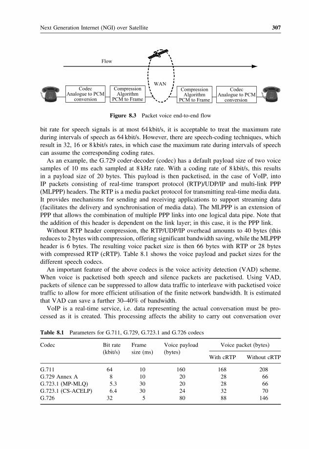
Next Generation Internet (NGI) over Satellite 307
CodecAnalogue to PCM
conversion
CompressionAlgorithm
PCM to Frame
CodecAnalogue to PCM
conversion
CompressionAlgorithm
PCM to Frame
WAN
Flow
Figure 8.3 Packet voice end-to-end flow
bit rate for speech signals is at most 64 kbit/s, it is acceptable to treat the maximum rateduring intervals of speech as 64 kbit/s. However, there are speech-coding techniques, whichresult in 32, 16 or 8 kbit/s rates, in which case the maximum rate during intervals of speechcan assume the corresponding coding rates.As an example, the G.729 coder-decoder (codec) has a default payload size of two voice
samples of 10 ms each sampled at 8 kHz rate. With a coding rate of 8 kbit/s, this resultsin a payload size of 20 bytes. This payload is then packetised, in the case of VoIP, intoIP packets consisting of real-time transport protocol (RTP)/UDP/IP and multi-link PPP(MLPPP) headers. The RTP is a media packet protocol for transmitting real-time media data.It provides mechanisms for sending and receiving applications to support streaming data(facilitates the delivery and synchronisation of media data). The MLPPP is an extension ofPPP that allows the combination of multiple PPP links into one logical data pipe. Note thatthe addition of this header is dependent on the link layer; in this case, it is the PPP link.Without RTP header compression, the RTP/UDP/IP overhead amounts to 40 bytes (this
reduces to 2 bytes with compression, offering significant bandwidth saving, while the MLPPPheader is 6 bytes. The resulting voice packet size is then 66 bytes with RTP or 28 byteswith compressed RTP (cRTP). Table 8.1 shows the voice payload and packet sizes for thedifferent speech codecs.An important feature of the above codecs is the voice activity detection (VAD) scheme.
When voice is packetised both speech and silence packets are packetised. Using VAD,packets of silence can be suppressed to allow data traffic to interleave with packetised voicetraffic to allow for more efficient utilisation of the finite network bandwidth. It is estimatedthat VAD can save a further 30–40% of bandwidth.VoIP is a real-time service, i.e. data representing the actual conversation must be pro-
cessed as it is created. This processing affects the ability to carry out conversation over
Table 8.1 Parameters for G.711, G.729, G.723.1 and G.726 codecs
Codec Bit rate(kbit/s)
Framesize (ms)
Voice payload(bytes)
Voice packet (bytes)
With cRTP Without cRTP
G.711 64 10 160 168 208G.729 Annex A 8 10 20 28 66G.723.1 (MP-MLQ) 5.3 30 20 28 66G.723.1 (CS-ACELP) 6.4 30 24 32 70G.726 32 5 80 88 146

308 Satellite Networking: Principles and Protocols
Table 8.2 Network delay specifications for voice applications(ITU-T, G114)
Range (ms) Description
0–150 Acceptable for most services andapplications by users
150–400 Acceptable provided that administratorsare aware of the transmission time andits impact on the transmission quality ofuser applications
>400 Unacceptable for general networkplanning purposes, however, only someexceptional cases exceed this limit
the communications channel (in this case the Internet). Excessive delays will mean thatthis ability is severely restricted. Variations in this delay (jitter) can possibly insert pausesor even break up words making the voice communication unintelligible. This is why mostpacketised voice applications use UDP to avoid recovering any packet loss or error.The ITU-T considers network delay for voice applications in Recommendation G.114.
This recommendation defines three bands of one-way delay as shown in Table 8.2.
8.4.6 On-off model for voice traffic
It has been widely accepted that modelling packet voice can be conveniently based onmimicking the characteristics of conversation – the alternating active and silent periods.A two-phase on-off process can represent a single packetised voice source. Measurementsindicate that the average active interval is 0.352 s in length while the average silent intervalis 0.650 s. An important characteristic of a voice source to capture is the distribution of theseintervals. A reasonable good approximation for the distribution of the active interval is anexponential distribution; however, this distribution does not represent the silent interval well.Nevertheless, it often assumes that both these intervals are exponentially distributed whenmodelling voice sources. The duration of voice calls (call holding time) and inter-arrivaltime between the calls can be characterised using telephony traffic models.During the active (on) interval, voice generates fixed size packets with a fixed inter-packet
spacing. This is the nature of voice encoders with fixed bit rate and fixed packetisation delay.This packet generation process follows a Poisson process with exponentially distributedinter-arrival times of mean T second or packet per second (pps) 1/T . As mentioned above,both the on and off intervals are exponentially distributed, giving rise to a two-state MMPPmodel. No packets are generated during the silent (off) interval. Figure 8.4 represents asingle voice source.The mean on period is 1/ while the mean off period is 1/. The mean packet inter-
arrival time is T s. A superposition of N such voice sources results in the following N -statebirth–death model, Figure 8.5, where a state represents the number of sources in the on state.This approach can model different voice codecs, with varying mean opinion score (MOS).
MOS is a systemof grading the voice quality of telephone connections.Awide rangeof listeners

Next Generation Internet (NGI) over Satellite 309
Poisson distribution withaverage 1/T packets/s
α
λ
On Off
Figure 8.4 A single voice source, represented by a two-state MMPP
Nα2αα (N–1)α
(N-1)λ 2λ λNλ
0 1 N N – 1……...
ppsT1
TN – 1
TN
Figure 8.5 Superposition of N voice sources with exponentially distributed inter-arrivals
judges the quality of a voice sample on a scale of one (bad) to five (excellent). The scores areaveraged to provide theMOS for the codec. The respective scores are 4.1 (G.711), 3.92 (G.729)and 3.8 (G.726). The parameters for this model are given in Table 8.2 with the additionalparameter representing packet inter-arrival time calculated using the following formula:
Inter_arrival_time= 1average_traffic_sent_pps
(8.7)
where
average_traffic_sent = codec_bit_ratepayload_size_bits
(8.8)
The mean off interval is typically 650ms while the mean on interval is 350ms.
8.4.7 Video traffic modelling
An emerging service of future multi-service networks is packet video communication. Packetvideo communication refers to the transmission of digitised and packetised video signals inreal time. The recent development in video compression standards, such as ITU-T H.261,ITU-T H.263, ISOMPEG-1, MPEG-2 and MPEG-4 [ISO99], has made it feasible to transportvideo over computer communication networks. Video images are represented by a seriesof frames in which the motion of the scene is reflected in small changes in sequentiallydisplayed frames. Frames are displayed at the terminal at some constant rate (e.g. 30 frames/s)enabling the human eye to integrate the differences within the frame into a moving scene.

310 Satellite Networking: Principles and Protocols
In terms of the amount of bandwidth consumed, video streaming is high on the list.Uncompressed, a one-second worth of video footage with a 300× 200 pixels resolutionat a playback rate of 30 frames per second would require 1.8 byte/s. Apart from the highthroughput requirements, video applications also put a stringent requirement in terms of lossand delay.There are several factors affecting the nature of video traffic. Among these are compression
techniques, coding time (on- or off-line), adaptiveness of the video application, supportedlevel of interactivity and the target quality (constant or variable). The output bit rate ofthe video encoder can either be controlled to produce a constant bit-rate stream which cansignificantly vary the quality of the video (CBR encoding), or left uncontrolled to producea more variable bit-rate stream for a more fixed quality video (VBR encoding). Variablebit-rate encoded video is expected to become a significant source of network traffic becauseof its advantages in statistical multiplexing gains and consistent video quality.Statistical properties of a video stream are quite different from that of voice or data. An
important property of video is the correlation structure between successive frames. Dependingon the type of video codecs, video images exhibit the following correlation components:
• Line correlation is defined as the level of correlation between data at one part of the imagewith data at the same part of the next line; also called spatial correlation.
• Frame correlation is defined as the level of correlation between data at one part of theimage with data at the same part of the next image; also called temporal correlation.
• Scene correlation is defined as the level of correlation between sequences of scenes.
Because of this correlation structure, it is no longer sufficient to capture the burst of videosources. Several other measurements are required to characterise video sources as accuratelyas possible. These measurements include:
• Autocorrelation function: measures the temporal variations.• Coefficient of variation: measures the multiplexing characteristics when variable ratesignals are statistically multiplexed.
• Bit-rate distribution: indicates together with the average bit rate and the variance, anapproximate requirement for the capacity.
As mentioned previously, VBR encoded video source is expected to be the dominant videotraffic source in the Internet. There are several statistical VBR source models. The modelsare grouped into four categories – auto-regressive (AR)/Markov-based models, transformexpand sample (TES), self-similar and analytical/IID. These models were developed basedon several attributes of the actual video source. For instance, a video conferencing session,which is based on the H.261 standards, would have very little scene changes and it isrecommended to use the dynamic AR (DAR) model. To model numerous scene changes(as in MPEG-coded movie sequences), Markov-based models or self-similar models can beused. The choice of which one to use is based on the number of parameters needed by themodel and the computational complexity involved. Self-similar models only require a singleparameter (Hurst or H parameter) but their computational complexity in generating samplesis high (because each sample is calculated from all previous samples). Markov chain modelson the other hand, require many parameters (in the form of transitional probabilities to model

Next Generation Internet (NGI) over Satellite 311
the scene changes), which again increase the computational complexity because it requiresmany calculations to generate a sample.
8.4.8 Multi-layer modelling for internet WWW traffic
The Internet operations consist of a chain of interactions between the users, applications,protocols and the network. This structured mechanism can be attributed to the layeredarchitecture employed in the Internet – a layering methodology was used in designing theInternet protocol stack. Hence, it is only natural to try to model Internet traffic by takinginto account the different effects each layer of the protocol stack has on the resulting traffic.The multi-layer modelling approach attempts to replicate the packet generation mechanism
as activated by the human users of the Internet and the Internet applications themselves.In a multi-layer approach, packets are generated in a hierarchical process. It starts witha human user arriving at a terminal and starting one or more Internet applications. Thisaction of invoking an application will start the chain of a succession of interactions betweenthe application and the underlying protocols on the source terminal and the correspondingprotocols and application on the destination terminal, culminating in the generation of packetsto be transported over the network. These interactions can generally be seen as ‘sessions’;the definition of a session is dependent on the application generating it, as we will see laterwhen applying this method in modelling the WWW application. An application generatesat least one, but usually more, sessions. Each session comprises one or more ‘flows’; eachflow in turn comprises packets. Therefore, there are three layers or levels encountered inthis multi-layer modelling approach – session, flow and packet levels.Take a scenario where a user arrives at a terminal and starts a WWW application by
launching a web browser. The user then clicks on a web link (or types in the web address)to access the web sites of interest. This action generates what we call HTTP sessions.The session is defined as the downloading of web pages from the same web server overa limited period; this does not discount the fact that other definitions of a session are alsopossible. The sessions in turn generate flows. Each flow is a succession of packets carryingthe information pertaining to a particular web page and packets are generated within flows.This hierarchical process is depicted in Figure 8.6.
Browser launched Browser exited
Sessions
Flows
Packets
Parameters
Session arrival rate
Flow arrival rateNo. of flow/session
Packet arrival rateNo. of packet/session
Figure 8.6 Multi-layer modelling

312 Satellite Networking: Principles and Protocols
Depicted in the diagram are the suggested parameters for this model. More complexmodels attempting to capture the self-similarity of web traffic might include the use ofheavy-tailed distributions to model any of the said parameters. Additional parameters suchas user think time and packet sizes are also modelled by heavy-tailed distributions. Whilethis type of model might be more accurate in capturing the characteristics of web traffic, itcomes with the added parameters and complexity.
8.5 Traffic engineering
A dilemma emerges for carriers and network operators: the cost to upgrade the infrastructureas it is nowadays for fixed and mobile telephone networks, is too high to be supportedby revenues coming from Internet services. Actually, revenues coming from voice-basedservices are quite high with respect to the ones derived by current Internet services. Therefore,to obtain cost effectiveness it is necessary to design networks that make an effective use ofbandwidth or, in a broader sense, of network resources.Traffic engineering (TE) is a solution that enables the fulfilment of all those requirements,
since it allows network resources to be used when necessary, where necessary and for thedesired amount of time. TE can be regarded as the ability of the network to control trafficflows dynamically in order to prevent congestion, to optimise the availability of resources,to choose routes for traffic flows while taking into account traffic loads and network state,to move traffic flows towards less congested paths, to react to traffic changes or failurestimely.The Internet has seen such a tremendous growth in the past few years. This growth has
correspondingly increased the requirements for network reliability, efficiency and servicequality. In order for the Internet service providers to meet these requirements, they need toexamine every aspect of their operational environment critically, assessing the opportunitiesto scale their networks and optimise performance. However, this is not a trivial task. Themain problem is with the simple building block on which the Internet was built – namelyIP routing based on the destination address and simple metrics like hop count or link cost.While this simplicity allows IP routing to scale to very large networks, it does not alwaysmake good use of network resources. Traffic engineering (TE) has thus emerged as a majorconsideration in the design and operation of large public Internet backbone networks. Whileits beginnings can be traced back to the development of the public switched telephonenetworks (PSTN), TE is fast finding a more crucial role to play in the design and operationof the Internet.
8.5.1 Traffic engineering principles
Traffic engineering is ‘concerned with the performance optimisation of networks’. It seeksto address the problem of efficient allocation of network resources to meet user constraintsand to maximise service provider benefit. The main goal of TE is to balance service andcost. The most important task is to calculate the right amount of resources; too much andthe cost will be excessive, too little will result in loss of business or lower productivity.As this service/cost balance is sensitive to the changes in business conditions, TE is thus acontinuous process to maintain an optimum balance.

Next Generation Internet (NGI) over Satellite 313
TE is a framework of processes whereby a network’s response to traffic demand (in termsof user constraints such as delay, throughput and reliability) and other stimuli such as failurecan be efficiently controlled. Its main objective is to ensure the network is able to support asmuch traffic as possible at their required level of quality and to do so by optimally utilisingits (the network’s) shared resources while minimising the costs associated with providing theservice. To do this requires efficient control and management of the traffic. This frameworkencompasses:
• traffic management through control of routing functions and QoS management;• capacity management through network control;• network planning.
Traffic management ensures that network performance is maximised under all conditionsincluding load shifts and failures (both node and link failures). Capacity management ensuresthat the network is designed and provisioned to meet performance objectives for networkdemands at minimum cost. Network planning ensures that the node and transport capacityis planned and deployed in advance of forecasted traffic growth. These functions form aninteracting feedback loop around the network as shown in Figure 8.7.The network (or system) shown in the figure is driven by a noisy traffic load (or signal)
comprising predictable average demand components added to unknown forecast errors andload variation components. The load variation components have different time constantsranging from instantaneous variations, hour-to-hour variations, day-to-day variations andweek-to-week or seasonal variations. Accordingly, the time constants of the feedback controlsare matched to the load variations and function to regulate the service provided by thenetwork through routing and capacity adjustments. Routing control typically applies onminutes, days or possibly real-time time scales while capacity and topology changes aremuch longer term (months to a year).Advancement in optical switching and transmission systems enables ever-increasing
amounts of available bandwidth. The effect is that the marginal cost (i.e. the cost associatedwith producing one additional unit of output) of bandwidth is rapidly being reduced: band-width is getting cheaper. The widespread deployment of such technologies is acceleratingand network providers are now able to sell high-bandwidth transnational and international
Actualload
Trafficdata
TE functions• Traffic management• Capacity management• Network planning
Load(+ uncertainties)
Forecastedload
Routing control Routing updates due to:• Capacity changes• Topology changes
Network
Figure 8.7 The traffic engineering process model

314 Satellite Networking: Principles and Protocols
connectivity simply by overprovisioning their networks. Logically, it would seem that inthe face of such developments and the abundance of available bandwidth, the need for TEwould be invalidated. On the contrary, TE still maintains its importance due principally tothe fact that both the number of users and their expectations are exponentially increasing inparallel to the exponential increase in available bandwidth. A corollary of Moore’s law says,‘As you increase the capacity of any system to accommodate user demand, user demandwill increase to consume system capacity’. Companies that have invested in such overpro-visioned networks will want to recoup their investments. Service differentiation chargingand usage-proportional pricing are mechanisms widely accepted for doing so. To implementthese mechanisms, simple and cost-effective mechanisms for monitoring usage and ensuringcustomers are receiving what they are requesting are required to make usage-proportionalpricing practical. Another important function of TE is to map traffic onto the physical infras-tructure to utilise resources optimally and to achieve good network performance. Hence, TEstill performs a useful function for both network operators and customers.
8.5.2 Internet traffic engineering
Internet TE is defined as that aspect of Internet network engineering dealing with the issue ofperformance evaluation and performance optimisation of operational IP networks. InternetTE encompasses the application of technology and scientific principles to the measurement,characterisation, modelling and control of Internet traffic. One of the main goals of InternetTE is to enhance the performance of an operational network, both in terms of traffic-handling capability and resource utilisation. Traffic-handling capability implies that IP trafficis transported through the network in the most efficient, reliable and expeditious mannerpossible. Network resources should be utilised efficiently and optimally while meeting theperformance objectives (delay, delay variation, packet loss and throughput) of the traffic.There are several functions contributing directly to this goal. One of them is the control and
optimisation of the routing function, to steer traffic through the network in the most effectiveway. Another important function is to facilitate reliable network operations. Mechanismsshould be provided that enhance network integrity and by embracing policies emphasisingnetwork survivability. This results in a minimisation of the vulnerability of the network toservice outages arising from errors, faults and failures occurring within the infrastructure.Effective TE is difficult to achieve in public IP networks due to the limited functional
capabilities of conventional IP technologies. One of the major problems lies in mappingtraffic flows onto the physical topology. In the Internet, mapping of flows onto a physicaltopology was heavily influenced by the routing protocols used. Traffic flows simply followedthe shortest path calculated by interior gateway protocols (IGP) used within autonomoussystems (AS) such as open shortest path first (OSPF) or intermediate system – intermediatesystem (IS-IS) and exterior gateway protocols (EGP) used to interconnect ASs such as bordergateway protocol 4 (BGP-4). These protocols are topology-driven and employ per-packetcontrol. Each router makes independent routing decisions based on the information in thepacket headers. By matching this information to a corresponding entry of a local instantiationof a synchronised routing area link state database, the next hop or route for the packet isthen determined. This determination is based on shortest path computations (often equatedto lowest cost) using simple additive link metrics.

Next Generation Internet (NGI) over Satellite 315
While this approach is highly distributed and scalable, there is a major flaw – it doesnot consider the characteristics of the offered traffic and network capacity constraints whendetermining the routes. The routing algorithm tends to route traffic onto the same links andinterfaces, significantly contributing to congestion and unbalanced networks. This resultsin parts of the network becoming over-utilised while other resources along alternate pathsremain under-utilised. This condition is commonly referred to as hyper aggregation. Whileit is possible to adjust the value of the metrics used in calculating the IGP routes, it soonbecame too complicated as the Internet core grows. Continuously adjusting the metrics alsoadds instability to the network. Hence, congested parts are often resolved by adding morebandwidth (overprovisioning), which is not treating the actual symptom of the problem inthe first place resulting in poor resource allocation or traffic mapping.The requirements for Internet TE is not that much different than that of telephony net-
works – to have a precise control over the routing function in order to achieve specificperformance objectives both in terms of traffic-related performance and resource-related per-formance (resource optimisation). However, the environment in which Internet TE is appliedis much more challenging due to the nature of the traffic and the operating environment ofthe Internet itself. Traffic on the Internet is becoming more multi-class (compared to fixed64 kbit/s voice in telephony networks) with different service requirements but contendingfor the same network resources. In this environment, TE needs to establish resource-sharingparameters to give preferential treatment to some service classes in accordance with a utilitymodel. The characteristics of the traffic are also proving to be a challenge – it exhibitsvery dynamic behaviour, which is still to be understood and tends to be highly asymmet-ric. The operating environment of the Internet is also an issue. Resources are augmentedconstantly and they fail on a regular basis. Routing of traffic, especially when traversingautonomous system boundaries, makes it difficult to correlate network topology with thetraffic flow. This makes it difficult to estimate the traffic matrix, the basic dataset neededfor TE.An initial attempt at circumventing some of the limitations of IP with respect to TE was
the introduction of a secondary technology with virtual circuits and traffic managementcapabilities (such as ATM) into the IP infrastructure. This is the overlay approach thatit consists of ATM switches at the core of the network surrounded by IP routers at theedges. The routers are logically interconnected using ATM PVC, usually in a fully meshedconfiguration. This approach allows virtual topologies to be defined and superimposed ontothe physical network topology. By collecting statistics on the PVC, a rudimentary trafficmatrix can be built. Overloaded links can be relieved by redirecting traffic to under-utilisedlinks.ATM was used mainly because of its superior switching performance compared to IP
routing at that time (there are currently IP routers that are as fast if not faster than anATM switch). ATM also afforded QoS and TE capabilities. However, there are fundamentaldrawbacks to this approach. Firstly, two networks of dissimilar technologies need to bebuilt and managed, adding to the increased complexity of network architecture and design.Reliability concerns also increase because the number of network elements existing in arouted path increases. Scalability is another issue especially in a fully meshed configurationwhereby the addition of another edge router would increase the number of PVC requiredby nn−1/2, where n is the number of nodes (the ‘n-squared’ problem). There is alsothe possibility of IP routing instability caused by multiple PVC failures following single

316 Satellite Networking: Principles and Protocols
link impairment in the ATM core. Concerning ATM itself, segmentation and reassembly(SAR) is difficult to perform at high speeds. SAR is required because of the difference inpacket formats between IP and ATM – ATM is cell-based with a fixed size of 53 bytes. IPpackets would need to be segmented into ATM cells at the ingress of an ATM network. Atthe egress, the cells would need to be reassembled into packets. Because of cell interleave,SAR must perform queuing and scheduling for a large number of VCs. Implementing this atSTM-32 (10Gbit/s) or higher speed is a very difficult task. Finally, the well-known problemof ATM cell tax – the overhead penalty with the use of ATM, which is approximately20% of the link bandwidth (e.g. 498Mbit/s is wasted on ATM cell overhead on an STM-16 or 2.4Gbit/s link,). Hence, there is a need to move away from the overlay modelto a more integrated solution. This was one of the motivations for the development ofMPLS.
8.6 Multi-protocol label switching (MPLS)
To improve on the best-effort service provided by the IP network layer protocol, new mech-anisms such as differentiated services (Diffserv) and integrated services (Intserv), have beendeveloped to support QoS. In the Diffserv architecture, services are given different prior-ities and resource allocations to support various types of QoS. In the Intserv architecture,resources have to be reserved for individual services. However, resource reservation for indi-vidual services does not scale well in large networks, since a large number of services haveto be supported, each maintaining its own state information in the network’s routers. Flow-based techniques such as multi-protocol label switching (MPLS) have also been developedto combine layer 2 and layer 3 functions to support QoS requirements.MPLS introduces a new connection-oriented paradigm, based on fixed-length labels. This
fixed-length label-switching concept is similar but not the same as that utilised by ATM.Among the key motivation for its development was to provide a mechanism for the seamlessintegration of IP and ATM. As discussed in the previous chapter, the occurrence of IPand ATM co-existence is something that is unavoidable in the pursuit for end-to-end QoSguarantees. However, the architectural differences between the two technologies prove tobe a stumbling block for their smooth interoperation. Overlay models have been proposedas solutions but they do not provide the single operating paradigm, which would simplifynetwork management and improve operational efficiency. MPLS is a peer model technology.Compared to the overlay model, a peer model integrates layer 2 switching with layer3 routing, yielding a single network infrastructure. Network nodes would typically haveintegrated routing and switching functions. This model also allows IP routing protocols toset up ATM connections and do not require address resolution protocols. While MPLS hassuccessfully merged the benefits of both IP and ATM, another application area in whichMPLS is fast establishing its usefulness is traffic engineering (TE). This also addresses othermajor network evolution problems – throughput and scalability.
8.6.1 MPLS forwarding paradigm
MPLS is a technology that combines layer 2 switching technologies with layer 3 routing tech-nologies. The primary objective of this new technology is to create a flexible networking fab-

Next Generation Internet (NGI) over Satellite 317
ric that provides increased performance and scalability. This includes TE capabilities. MPLSis designed to work with a variety of transport mechanisms; however, initial deploymentwill focus on leveraging ATM and frame relay, which are already deployed in large-scaleproviders’ networks.MPLS was initially designed in response to various inter-related problems with the cur-
rent IP infrastructure. These problems include scalability of IP networks to meet growingdemands, enabling differentiated levels of IP services to be provisioned, merging disparatetraffic types into a single network and improving operational efficiency in the face of toughcompetition. Network equipment manufacturers were among the first to recognise theseproblems and worked individually on their own proprietary solutions including tag switch-ing, IP switching, aggregate route-based IP switching (ARIS) and cell switch router (CSR).MPLS draws on these implementations in an effort to produce a widely applicable standard.Because the concepts of forwarding, switching and routing are fundamental in MPLS, a
concise definition of each one of them is given below:
• Forwarding is the process of receiving a packet on an input port and sending it out on anoutput port.
• Switching is forwarding process following the choosen path based information or knowl-edge of current network resources and loading conditions. Switching operates on layer 2header information.
• Routing is the process of setting routes to understand the next hop a packet shouldtake towards its destination within and between networks. It operates on layer 3 headerinformation.
The conventional IP forwarding mechanism (layer 3 routing) is based on the source–destination address pair gleaned from a packet’s header as the packet enters an IP networkvia a router. The router analyses this information and runs a routing algorithm. The routerwill then choose the next hop for the packet based on the results of the algorithm calculations(which are usually based on the shortest path to the next router). More importantly, thisfull packet header analysis must be performed on a hop-by-hop basis, i.e. at each routertraversed by the packet. Clearly, the IP packet forwarding paradigm is closely coupled tothe processor-intensive routing procedure.While the efficiency and simplicity of IP routing is widely acknowledged, there are a
number of issues brought about by large routed networks. One of the main issues is theuse of software components to realise the routing function. This adds latency to the packet.Higher speed, hardware-based routers are being designed and deployed, but these come at acost, which could easily escalate for large service providers’ or enterprise networks. There isalso difficulty in predicting the performance of a large meshed network based on traditionalrouting concepts.Layer 2 switching technologies such as ATM and frame relay utilise a different forwarding
mechanism, which is essentially based on a label-swapping algorithm. This is a muchsimpler mechanism and can readily be implemented in hardware, making this approachmuch faster and yielding a better price/performance advantage when compared to IP routing.ATM is also a connection-oriented technology, between any two points, traffic flows alonga predetermined path are established prior to the traffic being submitted to the network.Connection-oriented technology makes a network more predictable and manageable.
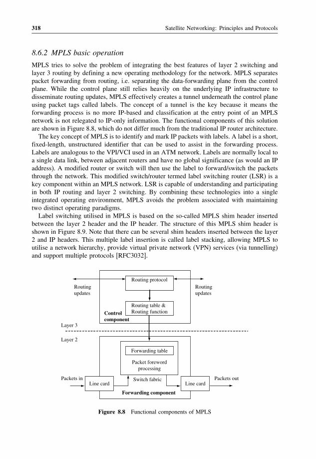
318 Satellite Networking: Principles and Protocols
8.6.2 MPLS basic operation
MPLS tries to solve the problem of integrating the best features of layer 2 switching andlayer 3 routing by defining a new operating methodology for the network. MPLS separatespacket forwarding from routing, i.e. separating the data-forwarding plane from the controlplane. While the control plane still relies heavily on the underlying IP infrastructure todisseminate routing updates, MPLS effectively creates a tunnel underneath the control planeusing packet tags called labels. The concept of a tunnel is the key because it means theforwarding process is no more IP-based and classification at the entry point of an MPLSnetwork is not relegated to IP-only information. The functional components of this solutionare shown in Figure 8.8, which do not differ much from the traditional IP router architecture.The key concept of MPLS is to identify and mark IP packets with labels. A label is a short,
fixed-length, unstructured identifier that can be used to assist in the forwarding process.Labels are analogous to the VPI/VCI used in an ATM network. Labels are normally local toa single data link, between adjacent routers and have no global significance (as would an IPaddress). A modified router or switch will then use the label to forward/switch the packetsthrough the network. This modified switch/router termed label switching router (LSR) is akey component within an MPLS network. LSR is capable of understanding and participatingin both IP routing and layer 2 switching. By combining these technologies into a singleintegrated operating environment, MPLS avoids the problem associated with maintainingtwo distinct operating paradigms.Label switching utilised in MPLS is based on the so-called MPLS shim header inserted
between the layer 2 header and the IP header. The structure of this MPLS shim header isshown in Figure 8.9. Note that there can be several shim headers inserted between the layer2 and IP headers. This multiple label insertion is called label stacking, allowing MPLS toutilise a network hierarchy, provide virtual private network (VPN) services (via tunnelling)and support multiple protocols [RFC3032].
Routingupdates
Routingupdates
Switch fabric
Controlcomponent
Forwarding table
Forwarding component
Packet forewordprocessing
Line cardPackets in Packets out
Layer 3
Layer 2
Routing protocol
Line card
Routing table &Routing function
Figure 8.8 Functional components of MPLS

Next Generation Internet (NGI) over Satellite 319
Layer 2header
MPLS shimheader
MPLS shimheader
IP header
Label (20 bits)EXP
(3 bits)S
(1 bit)TTL
(8 bits)
EXP: Experimental functionsS: Level of stack indicator, 1 indicates the bottom of the stackTTL: Time to live
Figure 8.9 MPLS shim header structure
The MPLS forwarding mechanism differs significantly from conventional hop-by-hoprouting. The LSR participates in IP routing to understand the network topology as seen fromthe layer 3 perspective. This routing knowledge is then applied, together with the results ofanalysing the IP header, to assign labels to packets entering the network. Viewed on an end-to-end basis, these labels combine to define paths called label switched paths (LSP). LSP aresimilar to VCs utilised by switching technologies. This similarity is reflected in the benefitsafforded in terms of network predictability and manageability. LSP also enable a layer 2forwarding mechanism (label swapping) to be utilised. As mentioned earlier, label swappingis readily implemented in hardware, allowing it to operate at typically higher speeds thanrouting. To control the path of LSP effectively, each LSP can be assigned one or moreattributes (see Table 8.3). These attributes will be considered in computing the path for theLSP. There are two ways to set up an LSP – control-driven (i.e. hop-by-hop) and explicitly
Table 8.3 LSP attributes
Attribute name Meaning of attribute
Bandwidth The minimum requirement on the reserverable bandwidth for the LSP tobe set up along that path
Path attribute An attribute that decides whether the path for the LSP should bemanually specified or dynamically computed by constraint-based routing
Setup priority The attribute that decides which LSP will get the resource when multipleLSPs compete for it
Holding priority The attribute that decides whether an established LSP should bepre-empted by a new LSP
Affinity An administratively specified property of an LSP to achieve somedesired LSP placement
Adaptability Whether to switch the LSP to a more optimal path when one becomesavailable
Resilience The attribute that decides to re-route the LSP when the current path fails

320 Satellite Networking: Principles and Protocols
routed LSP (ER-LSP). Since the overhead of manually configuring LSP is very high, thereis a need on service providers’ behalf to automate the process by using signalling protocols.These signalling protocols distribute labels and establish the LSP forwarding state in thenetwork nodes. A label distribution protocol (LDP) is used to set up a control-driven LSPwhile RSVP-TE and CR-LDP are the two signalling protocols used for setting up ER-LSP.The label swapping algorithm is a more efficient form of packet forwarding, compared
to the longest address match-forwarding algorithm used in conventional layer 3 routing.The label-swapping algorithm requires packet classification at the point of entry into thenetwork from the ingress label edge router (LER) to assign an initial label to each packet.Labels are bound to forwarding equivalent classes (FEC). An FEC is defined as a groupof packets that can be treated in an equivalent manner for purposes of forwarding (sharethe same requirements for their transport). The definition of FEC can be quite general.FEC can relate to service requirements for a given set of packets or simply on source anddestination address prefixes. All packets in such a group get the same treatment en route tothe destination. In a conventional packet forwarding mechanism, FEC represent groups ofpackets with the same destination address; then the FEC should have their respective nexthops. However, it is the intermediate nodes processing the FEC grouping and mapping. Asopposed to conventional IP forwarding, in MPLS, it is the edge-to-edge router assigningpackets to a particular FEC when the packet enters the network. Each LSR then builds atable to specify how to forward packets. This forwarding table, called a label informationbase (LIB), comprises FEC-to-label bindings.In the core of the network, LSR ignore the header of network layer packets and simply
forward the packet using the label with the label-swapping algorithm. When a labelled packetarrives at a switch, the forwarding component uses the pairing, input port number/incominginterface, incoming label value, to perform an exact match search of its forwarding table.When a match is found, the forwarding component retrieves the pairing, output port num-ber/outgoing interface, outgoing label value, and the next-hop address from the forwardingtable. The forwarding component then replaces the incoming label with the outgoing labeland directs the packet to the outbound interface for transmission to the next hop in the LSP.When the labelled packet arrives at the egress LER (point of exit from the network), theforwarding component searches its forwarding table. If the next hop is not a label switch, theegress LSR discards (pop-off) the label and forwards the packet using conventional longestmatch IP forwarding. Figure 8.10 shows the label swapping process.
• Perform Layer 3 lookup.• Map to FEC.• Attach label and forward out appropriate interface according to FEC.
• Perform exact match on incoming label.• Lookup outgoing interface and label.• Swap labels and forward out appropriate interface.
• Pop-off label.• Perform Layer 3 lookup.• Forward according to Layer 3 lookup.
Ingress LERA
Interior LSRB
Egress LERC
IP packet
IP packet Label HostZ
IP packet Label
IP packet
Figure 8.10 Label swapping and forwarding process

Next Generation Internet (NGI) over Satellite 321
LSP can also allow minimising the number of hops, to meet certain bandwidth require-ments, to support precise performance requirements, to bypass potential points of congestion,to direct traffic away from the default path, or simply to force traffic across certain linksor nodes in the network. Label swapping gives a huge flexibility in the way that it assignspackets to FEC. This is because the label swapping forwarding algorithm is able to takeany type of user traffic, associate it with an FEC, and map the FEC to an LSP that hasbeen specifically designed to satisfy the FEC requirements; therefore allowing a high levelof control in the network. These are the features, which lend credibility to MPLS to supporttraffic engineering (TE). We will discuss further the application of MPLS in TE in a latersection.
8.6.3 MPLS and Diffserv interworking
The introduction of a QoS enabled protocol into a network supporting various other QoSprotocols would undoubtedly lead to the requirement for these protocols to interwork witheach other in a seamless fashion. This requirement is essential to the QoS guarantees to thepackets traversing the network. It is an important issue of interworking MPLS with Diffservand ATM.The combination of MPLS and Diffserv provides a scheme, which is mutually beneficial
for both. Path-oriented MPLS can provide Diffserv with a potentially faster and morepredictable path protection and restoration capabilities in the face of topology changes, ascompared to conventional hop-by-hop routed IP networks. Diffserv, on the other hand, canact as QoS architecture for MPLS. Combined, MPLS and Diffserv can provide the flexibilityto provide different treatments to certain QoS classes requiring path protection.IETF3270 specifies a solution for supporting Diffserv behaviour aggregates (BA) and
their corresponding per hop behaviours (PHB) over an MPLS network. The key issue forsupporting Diffserv over MPLS is how to map Diffserv to MPLS. This is because LSRcannot see an IP packet’s header and the associated DSCP values, which links the packetto its BA and consequently to its PHB, as PHB determines the scheduling treatment and, insome cases, the drop probability of a packet. LSR only look for labels, read their contentsand decide the next hop. For an MPLS domain to handle a Diffserv packet appropriately,the labels must contain some information regarding the treatment on the packet.The solution to this problem is to map the six-bit DSCP values to the three-bit EXP field
of the MPLS shim header. This solution relies on the combined use of two types of LSP:
• A LSP that can transport multiple ordered aggregates, so that the EXP field of the MPLSshim header conveys to the LSR with the PHB applied to the packet (covering bothinformation about the packet’s scheduling treatment and its drop precedence). An orderedaggregate (OA) is a set of BAs sharing an ordering constraint. Such an LSP refers to asEXP-Inferred-PSC-LSP (E-LSP), when defining PSC as a PHB scheduling class. The setof one or more PHB applies to the BAs belonging to a given OA. With this method, itcan map up to eight DSCPs to a single E-LSP.
• A LSP that can transport only a single ordered aggregate, so that the LSR exclusively inferthe packet scheduling treatment exclusively from the packet label value. The packet dropprecedence is conveyed in the EXP field of the MPLS shim header or in the encapsulatinglink layer specific selective drop mechanism, where in such cases the MPLS shim header

322 Satellite Networking: Principles and Protocols
is not used (e.g. MPLS over ATM). Such LSP refer to label-only-inferred-PSC-LSP(L-LSP). With this method, an individual L-LSP has a dedicated Diffserv code point.
8.6.4 MPLS and ATM interworking
MPLS and ATM can interwork at network edges to support and bring multiple servicesinto the network core of an MPLS domain. In this instance, ATM connections need to betransparent across the MPLS domain over MPLS LSP. Transparency in this context meansthat ATM-based services should be carried over the domain unaffected.There are several requirements that need to be addressed concerning MPLS and ATM
interworking. Some of these requirements are:
• The ability to multiplex multiple ATM connections (VPC and/or VCC) into an MPLSLSP.
• Support for the traffic contracts and QoS commitments made to the ATM connections.• The ability to carry all the AAL types transparently.• Transport of RM cells and CLP information from the ATM cell header.
Transport of ATM traffic over the MPLS uses only the two-level LSP stack. The two-levelstack specifies two types of LSP. A transport LSP (T-LSP) transports traffic between twoATM-MPLS interworking devices located at the boundaries of the ATM-MPLS networks.This traffic can consist of a number of ATM connections, each associated with an ATMservice category. The outer label of the stack (known as a transport label) defines a T-LSP,i.e. the S field of the shim header is set to 0 to indicate it is not the bottom of the stack. Thesecond type of LSP is an interworking LSP (I-LSP), nested within the T-LSP (identified byan interworking label), which carries traffic associated with a particular ATM connection, i.e.one I-LSP is used for an ATM connection. I-LSP also provides support for VP/VC switchingfunctions. One T-LSP may carry more than one I-LSP. Because an ATM connection isbi-directional while an LSP is unidirectional, two different I-LSPs, one for each directionof the ATM connection, are required to support a single ATM connection. Figure 8.11shows the relationship between T-LSP, I-LSP and ATM connections. The interworking unit(IWU) encapsulates ATM cells in the ATM-to-MPLS direction, into a MPLS frame. For theMPLS-to-ATM direction, the IWU reconstructs the ATM cells.With regarding to support of ATM traffic contracts and QoS commitments to ATM
connections, the mapping of ATM connections to I-LSP and subsequently to T-LSP musttake into consideration the TE properties of the LSP. There are two methods to implementthis.Firstly, a single T-LSP can multiplex all the I-LSP associated to several ATM connections
with different service categories. This type of LSP is termed class multiplexed LSP. It groupsthe ATM service categories into groups and maps each group into a single LSP. As anexample for the second scenario, it groups the categories initially into real-time traffic (CBRand rt-VBR) and non-real-time traffic (nrt-VBR, ABR, UBR). It transports the real-timetraffic over one T-LSP while the non-real-time traffic over another T-LSP. It can implementclass multiplexed LSP by using either L-LSP or E-LSP. Class multiplexed L-LSP must meetthe most stringent QoS requirements of the ATM connections transported by the LSP. Thisis because L-LSP treats every packet going through it the same. Class multiplexed E-LSP, on

Next Generation Internet (NGI) over Satellite 323
(a)
ATMnetwork
ATMnetwork
MPLSnetwork
ATM VP/VC link
IWU
Transport LSP Interworking LSP
ATM MPLS
IWU
MPLS ATM
(b)
Figure 8.11 ATM-MPLS networks interworking. (a) ATM-MPLS network interworking architecure.(b) the relationship between transport LSP, interworking LSP and ATM link
the other hand, identifies the scheduling and dropping treatments applied to a packet basedon the value of the EXP field inside the T-LSP label. Each LSR can then apply differentscheduling treatments for each packet transported over the LSP. This method also requiresa mapping between ATM service categories and the EXP bits.Secondly, an individual T-LSP is allocated to each ATM service class. This LSP is termed
class based LSP. There can be more than one connection per ATM service class. In thiscase, the MPLS domain would search for a path that meets the requirement of one of theconnections.
8.6.5 MPLS with traffic engineering (MPLS-TE)
An MPLS domain still requires IGP such as OSPF and IS-IS to calculate routes through thedomain. Once it has computed a route, it uses signalling protocols to establish LSP alongthe route. Traffic that satisfies a given FEC associated with a particular LSP is then sentdown the LSP.The basic problem addressed by TE is the mapping of traffic onto routes to achieve
the performance objectives of the traffic while optimising the resources at the same time.Conventional IGP such as open shortest path first (OSPF), makes use of pure destinationaddress-based forwarding. It selects routes based on simply the least cost metric (or shortestpath). Traffic from different routers therefore converge on this particular path, leaving theother paths under-utilised. If the selected path becomes congested, there is no procedure tooff-load some of the traffic onto the alternative path.For TE purposes, the LSR should build a TE database within the MPLS domain. This
database holds additional information regarding the state of a particular link. Additionallink attributes may include maximum link bandwidth, maximum reserverable bandwidth,current bandwidth utilisation, current bandwidth reservation and link affinity or colour(an administratively specified property of the link). These additional attributes are carried

324 Satellite Networking: Principles and Protocols
by TE extensions of existing IGP – OSPF-TE and IS-IS TE. This enhanced database willthen be used by the signalling protocols to establish ER-LSP.The IETF has specified LDP as the signalling protocol for setting up LSP. LDP is usually
used for hop-by-hop LSP set up, whereby each LSR determines the next interface to route theLSP based on its layer 3 routing topology database. This means that hop-by-hop LSP followthe path that normal layer 3 routed packets will take. There are two signalling protocols:RSVP-TE (RSVP with TE extension) and CR-LDP (constraint-based routing LDP) controlthe LSP for TE applications. These protocols are used to establish traffic-engineered ER-LSP. An explicit route specifies all the routers across the network with a precise sequenceof steps from ingress to egress. Packets must follow this route strictly. Explicit routing isuseful to force an LSP down a path that is different from the one offered by the routingprotocol. Explicit routing can also be used to distribute traffic in a busy network, to routearound failed or congestion hot spots, or to provide pre-allocated back-up LSP to protectagainst network failures.
8.7 Internet protocol version 6 (IPv6)
Recently, there has been increasing interest in research, development and deployment inIPv6. The protocol itself it very easy to understands. Like any new protocols and networks,it faces a great challenge in compatibility with the existing operational networks, balancingeconomic cost and benefit of the evolution towards IPv6, and smooth change over from IPv4to IPv6. It is also a great leap. However, most of these are out of the scope of this book.Here we only discuss the basics of IPv6 and issues on IPv6 networking over satellites.
8.7.1 Basics of internet protocol version 6 (IPv6)
The IP version 6 (IPv6), which the IETF have developed as a replacement for the current IPv4protocol, incorporates support for a flow label within the packet header, which the networkcan use to identify flows, much as VPI/VCI are used to identify streams of ATM cells.RSVP helps to associate with each flow a flow specification (flow spec) that characterisesthe traffic parameters of the flow, much as the ATM traffic contract is associated with anATM connection.IPv6 can support integrated services with QoS with such mechanisms and the definition
of protocols like RSVP. It extends the IPv4 protocol to address the problems of the currentInternet to:
• support more host addresses;• reduce the size of the routing table;• simplify the protocol to allow routers to process packets faster;• have better security (authentication and privacy);• provide QoS to different types of services including real-time data;• aid multicasting (allow scopes);• allow mobility (roam without changing address);• allow the protocol to evolve;• permit coexisting of old and new protocols.

Next Generation Internet (NGI) over Satellite 325
Flow label
Payload length Next header
0 8 16 24 (31)
Version
Hop limit
0 8 16 24
Priority
Source Address
Source Address
Source Address
Source Address
Destination Address
Destination Address
Destination Address
Destination Address
Figure 8.12 IPv6 packet header format
Compared to IPv4, IPv6 has made significant changes to the IPv4 packet format in orderto achieve the objectives of the next generation Internet with the network layer functions.Figure 8.12 shows the IPv6 packet header format. The functions of its fields is summarisedas the following:
• The version field has the same function as IPv4. It is 6 for IPv6 and 4 for IPv4.• The priority field identifies packets with different real-time delivery requirements.• The flow label field is used to allow source and destination to set up a pseudo-connectionwith particular properties and requirements.
• The payload field is the number of bytes following the 40-byte header, instead of totallength in IPv4.
• The next header field tells which transport handler to pass the packet to, like the protocolfield in the IPv4.
• The hop limit field is a counter used to limit packet lifetime to prevent the packet stayingin the network forever, like the time to live field in IPv4.
• The source and destination addresses indicate the network number and host number, fourtimes larger than IPv4
• There are also extension headers like the options in IPv4. Table 8.4 shows the IPv6extension header.
Each extension header consists of next header field, and fields of type, length and value.In IPv6, the optional features become mandatory features: security, mobility, multicast andtransitions. IPv6 tries to achieve an efficient and extensible IP datagram in that:
• the IP header contains less fields that enable efficient routing and performance;• extensibility of header offers better options;• the flow label gives efficient processing of IP datagram.

326 Satellite Networking: Principles and Protocols
Table 8.4 IPv6 extension headers
Extension header Description
Hop-by-hop options Miscellaneous information for routersDestination options Additional information for the destinationRouting Loose list of routers to visitFragmentation Management of datagram fragmentsAuthentication Verification of the sender’s identityEncrypted security payload Information about the encrypted contents
8.7.2 IPv6 addressing
IPv6 has introduced a large addressing space to address the shortage of IPv4 addresses. Ituses 128 bits for addresses, four times the 32 bits of the current IPv4 address. It allowsabout 3 4×1038 possible addressable nodes, equivalent to 1030 addresses per person on theplanet. Therefore, we should never exhaust IPv6 addresses in the future Internet.In IPv6, there is no hidden network and host. All hosts can be servers and are reachable
from outside. This is called global reachability. It supports end-to-end security, flexibleaddressing and multiple levels of hierarchy in the address space.It allows autoconfiguration, link-address encapsulation, plug & play, aggregation, multi-
homing and renumbering.The address format is x:x:x:x:x:x:x:x, where x is a 16-bit hexadecimal field. For
example, herewith is an IPv6 address:
2001 FFFF 1234 0000 0000 C1C0 ABCD 8760
It is case sensitive and is different from the following address:
2001 FFFF 1234 0000 0000 c1c0:abcd 8760
Leading zeros in a field are optional:
2001 0 1234 0 0 C1C0 ABCD 8760
Successive fields of 0 can be written as ‘: :’. For example:
2001 0 1234 C1C0 FFCD 8760
We can also rewrite the following addresses:
FF02 0 0 0 0 0 0 1 into FF02 1
0 0 0 0 0 0 0 1 into 1 and
0 0 0 0 0 0 0 0 into

Next Generation Internet (NGI) over Satellite 327
But we can only use ‘: :’ once in an address. An address like this is not valid:
2001 1234 C1C0 FFCD 8760
IPv6 addresses are also different in a URL. It only allows fully qualified domain names(FQDN). An IPv6 address is enclosed in brackets such as http://[2001:1:4F3A::20F6:AE14]:8080/index.html. Therefore, URL parsers have to be modified, and it could be a barrier forusers.IPv6 address architecture defines different types of address: unicast, multicast and anycast.
There are also unspecified and loop back addresses. Unspecified addresses can be used as aplaceholder when no address is available, such as in an initial DHCP request and duplicateaddress detection (DAD). Loop back addresses identify the node itself as the local host using127.0.0.1 in IPv4 and 0:0:0:0:0:0:0:1 or simply : :1 in IPv6. It can be usedfor testing IPv6 stack availability, for example, ping6 : :1.The scope of IPv6 addresses allows link-local and site-local. It allows aggregatable global
addresses including multicast and anycast, but there is no broadcast address in IPv6.The link-local scoped address is new in IPv6: ‘scope = local link’ (i.e. WLAN, subnet).
It can only be used between nodes of the same link, but cannot be routed. It allowsautoconfiguration on each interface using a prefix plus interface identifier (based on MACaddress) in the format of ‘FE80:0:0:0:<interface identifier>’. It gives every node an IPv6address for start-up communications.The site-local scoped address has ‘scope = site (a network of links)’. It can only be used
between nodes of the same site, but cannot be routed outside the site, and is very similar toIPv4 private addresses. There is no default configuration mechanism to assign it. It has theformat of ‘FEC0:0:0:<subnet id>:<interface id>’ where the <subnet id> has 16 bits capableof addressing 64 k subnets. It can be used to number a site before connecting to the Internetor for private addresses (e.g. local printers).The aggregatable global address is for generic use and allows globally reach. The address
is allocated by IANA (Internet assigned number authority) with a hierarchy of tier-1 providersas top-level aggregator (TLA), intermediate providers as next-level aggregator (NLA), andfinally sites and subnets at the bottom, as shown in Figure 8.13.IPv6 support multicast, i.e. one-to-many communications. Multicast is used instead, mostly
on local links. The scope of the addresses can be node, link, site, organisation and global.Unlike IPv4, it does not use time to live (TTL). IPv6 multicast addresses have a formatof ‘FF<flags><scope>::<multicast group>’. Any IPv6 node should recognise the followingaddresses as identifying itself (see Table 8.5):
• link-local address for each interface;• assigned (manually or automatically) unicast/anycast addresses;
TLA RES NLAs SLA Interface ID
48 bits 16 bits 64 bits
Figure 8.13 Structure of the aggregatable global address

328 Satellite Networking: Principles and Protocols
Table 8.5 Some reserved multicast addresses
Address Scope Use
FF01::1 Interface-local All nodesFF02::1 Link-local All nodesFF01::2 Interface-local All routersFF02::2 Link-local All routersFF05::2 Site-local All routersFF02::1:FFXX:XXXX Link-local Solicited nodes
• loop back address;• all-nodes multicast address;• solicited-node multicast address for each of its assigned unicast and anycast address;• multicast address of all other groups to which the host belongs.
The anycast address is one-to-nearest, which is great for discovery functions. Anycastaddresses are indistinguishable from unicast addresses, as they are allocated from the unicastaddress space. Some anycast addresses are reserved for specific uses, for example, router-subnet, mobile IPv6 home-agent discovery and DNS discovery. Table 8.6 shows the IPv6address architecture.
Table 8.6 IPv6 addressing architecture
Prefix Hex Size Allocation
0000 0000 0000-00FF 1/256 Reserved0000 0001 0100-01FF 1/256 Unassigned0000 001 0200-03FF 1/128 NSAP0000 010 0400-05FF 1/128 Unassigned0000 011 0600-07FF 1/128 Unassigned0000 1 0800-0FFF 1/32 Unassigned0001 1000-1FFF 1/16 Unassigned001 2000-3FFF 1/8 Aggregatable:
IANA to registry010, 011, 100, 101, 110 4000-CFFF 5/8 Unassigned1110 D000-EFFF 1/16 Unassigned1111 0 F000-F7FF 1/32 Unassigned1111 10 F800-FBFF 1/64 Unassigned1111 110 FC00-FDFF 1/128 Unassigned1111 1110 0 FE00-FE7F 1/512 Unassigned1111 1110 10 F800-FEBF 1/1024 Link-local1111 1110 11 FEC0-FEFF 1/1024 Site-local1111 1111 FF00-FFFF 1/256 Multicast

Next Generation Internet (NGI) over Satellite 329
When a node has many IPv6 addresses, to select which one to use for the source anddestination addresses for a given communication, one should address the following issues:
• scoped addresses are unreachable depending on the destination;• preferred vs. deprecated addresses;• IPv4 or IPv6 when DNS returns both;• IPv4 local scope (169.254/16) and IPv6 global scope;• IPv6 local scope and IPv4 global scope;• mobile IP addresses, temporary addresses, scope addresses, etc.
8.7.3 IPv6 networks over satellites
We have learnt through the book to treat the satellite networks as generic networks withdifferent characteristics and IP networks interworking with other different networking tech-nologies. Therefore, all the concepts, principles and techniques can be applied to IPv6 oversatellites. Though IP has been designed for internetworking purposes, the implementationand deployment of any new version or new type of protocol always face some problems.These also have potential impacts on all the layers of protocols including trade-offs betweenprocessing power, buffer space, bandwidth, complexity, implementation costs and humanfactors. To be concise, we will only summarise the issues and scenarios on internetworkingbetween IPv4 and IPv6 as the following:
• Satellite network is IPv6 enabled: this raises issues on user terminals and terrestrial IPnetworks. We can imagine that it is not practical to upgrade them all at the same time.Hence, one of the great challenges is how to evolve from current IP networking oversatellite towards the next generation network over satellites. Tunnelling from IPv4 to IPv6or from IPv6 to IPv4 is inevitable, hence generating great overheads. Even if all networksare IPv6 enabled, there is still a bandwidth efficiency problem due to the large overheadof IPv6.
• Satellite network is IPv4 enabled: this faces similar problems to the previous scenario,however, satellite networks may be forced to evolve to IPv6 if all terrestrial networks andterminals start to run IPv6. In terrestrial networks when bandwidth is plentiful, we canafford to delay the evolution. In satellite networks, such a strategy may not be practical.Hence, timing, stable IPv6 technologies and evolution strategies all play an important role.
8.7.4 IPv6 transitions
The transition of IPv6 towards next-generation networks is a very important aspect. Manynew technologies failed to succeed because of the lack of transition scenarios and tools. IPv6was designed with transition in mind from the beginning. For end systems, it uses a dualstack approach as show in Figure 8.14; and for network integration, it uses tunnels (somesort of translation from IPv6-only networks to IPv4-only networks).Figure 8.14 illustrates a node that has both IPv4 and IPv6 stacks and addresses. The IPv6-
enabled application requests both IPv4 and IPv6 destination addresses. The DNS resolverreturns IPv6, IPv4 or both addresses to the application. IPv6/IPv4 applications choose theaddress and then can communicate with IPv4 nodes via IPv4 or with IPv6 nodes via IPv6.
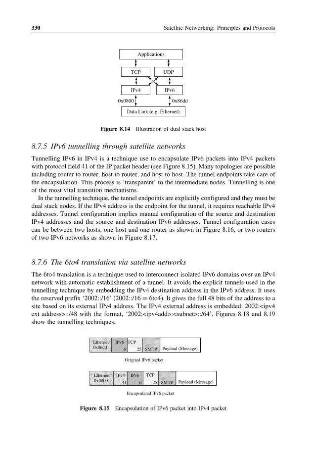
330 Satellite Networking: Principles and Protocols
Data Link (e.g. Ethernet)
IPv4 IPv6
0x0800 0x86dd
TCP UDP
Applications
Figure 8.14 Illustration of dual stack host
8.7.5 IPv6 tunnelling through satellite networks
Tunnelling IPv6 in IPv4 is a technique use to encapsulate IPv6 packets into IPv4 packetswith protocol field 41 of the IP packet header (see Figure 8.15). Many topologies are possibleincluding router to router, host to router, and host to host. The tunnel endpoints take care ofthe encapsulation. This process is ‘transparent’ to the intermediate nodes. Tunnelling is oneof the most vital transition mechanisms.In the tunnelling technique, the tunnel endpoints are explicitly configured and they must be
dual stack nodes. If the IPv4 address is the endpoint for the tunnel, it requires reachable IPv4addresses. Tunnel configuration implies manual configuration of the source and destinationIPv4 addresses and the source and destination IPv6 addresses. Tunnel configuration casescan be between two hosts, one host and one router as shown in Figure 8.16, or two routersof two IPv6 networks as shown in Figure 8.17.
8.7.6 The 6to4 translation via satellite networks
The 6to4 translation is a technique used to interconnect isolated IPv6 domains over an IPv4network with automatic establishment of a tunnel. It avoids the explicit tunnels used in thetunnelling technique by embedding the IPv4 destination address in the IPv6 address. It usesthe reserved prefix ‘2002::/16’ (2002::/16 ≡ 6to4). It gives the full 48 bits of the address to asite based on its external IPv4 address. The IPv4 external address is embedded: 2002:<ipv4ext address>::/48 with the format, ‘2002:<ipv4add>:<subnet>::/64’. Figures 8.18 and 8.19show the tunnelling techniques.
Ethernet0x0800
IPv4
41
IPv6
6
TCP
25 SMTP Payload (Message)
Encapsulated IPv6 packet
Original IPv6 packet
Ethernet0x86dd
IPv6
6 SMTP Payload (Message)TCP
25
Figure 8.15 Encapsulation of IPv6 packet into IPv4 packet

Next Generation Internet (NGI) over Satellite 331
Satellite as Access Network
IPv4 network
RouterIPv6 in IPv4 IPv6
IPv4 address: 192.168.1.1IPv6 address: 3ffe:b00:a:1::1
src = 3ffe:b00:a:1::1des = 3ffe:b00:a:3::2
src = 3ffe:b00:a:1::1des = 3ffe:b00:a:3::2
IPv6 address:3ffe:b00:a:3::2
IP addressv4: 192.168.2.1v6: 3ffe:b00:a:1::2 IPv6 address
3ffe:b00:a:5::1
IPv6 headerPayload IPv6 headerPayload
src = 192.168.1.1des = 192.168.2.1
IPv6 headerPayload IPv4 header
Figure 8.16 Host to router tunnelling through satellite access network
Satellite as Access Network
IPv4 network
RouterIPv6 in IPv4IPv6
IPv6 address:3ffe:b00:a:1::1
src =3ffe:b00:a:1::1des=3ffe:b00:a:3::2
src = 3ffe:b00:a:1::1des = 3ffe:b00:a:3::2
IPv6 address:3ffe:b00:a:3::2IPv4 address:
192.168.2.1
IPv6 header Payload IPv6 headerPayload
src = 192.168.1.1des = 192.168.2.1
IPv6 headerPayload IPv4 header
RouterIPv6
IPv4 address:192.168.1.1
Figure 8.17 Router to router tunnelling through satellite core network
Satellite as Access Network
IPv4 network6to4
RouterIPv6 in IPv4 IPv6
IPv4 address: 192.168.1.1IPv6 address: 2002:c0a8:101:1::1
src = 2002.c0a8:101:1::1des = 2002:c0a8:201:2::2
IPv6 address:200:c0a8:101:1::1
IPv4 address192.168.2.1
IPv6 headerPayload IPv6 headerPayload
src = 192.168.1.1des = 192.168.2.1
IPv6 headerPayload IPv4 header
src = 2002:c0a8:101:1::1des = 2002:c0a8:201:2::2
Figure 8.18 The 6to4 translation via satellite access network
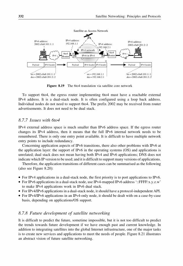
332 Satellite Networking: Principles and Protocols
Satellite as Access Network
IPv4 network6to4
RouterIPv6 in IPv4IPv6
IPv6 address:2002:c0a8:101:1::1
src = 2002:c0a8:101:1::1des = 2002:c0a8:201:2::2
IPv6 address:2002:c0a8:201:2::2IPv4 address:
192.168.2.1
IPv6 headerPayload IPv6 headerPayload
src = 192.168.1.1des = 192.168.2.1
IPv6 headerPayload IPv4 header
6to4Router IPv6
IPv4 address:192.168.1.1
src = 2002:c0a8:101:1::1des = 2002:c0a8:201:2::2
Figure 8.19 The 6to4 translation via satellite core network
To support 6to4, the egress router implementing 6to4 must have a reachable externalIPv4 address. It is a dual-stack node. It is often configured using a loop back address.Individual nodes do not need to support 6to4. The prefix 2002 may be received from routeradvertisements. It does not need to be dual stack.
8.7.7 Issues with 6to4
IPv4 external address space is much smaller than IPv6 address space. If the egress routerchanges its IPv4 address, then it means that the full IPv6 internal network needs to berenumbered. There is only one entry point available. It is difficult to have multiple networkentry points to include redundancy.Concerning application aspects of IPv6 transitions, there also other problems with IPv6 at
the application layer: the support of IPv6 in the operating systems (OS) and applications isunrelated; dual stack does not mean having both IPv4 and IPv6 applications; DNS does notindicate which IP version to be used; and it is difficult to support many versions of applications.Therefore, the application transitions of different cases can be summarised as the following
(also see Figure 8.20):
• For IPv4 applications in a dual-stack node, the first priority is to port applications to IPv6.• For IPv6 applications in a dual-stack node, use IPv4-mapped IPv6 address ‘::FFFF:x.y.z.w’to make IPv4 applications work in IPv6 dual stack.
• For IPv4/IPv6 applications in a dual-stack node, it should have a protocol-independent API.• For IPv4/IPv6 applications in an IPv4-only node, it should be dealt with on a case-by-casebasis, depending on applications/OS support.
8.7.8 Future development of satellite networking
It is difficult to predict the future, sometime impossible, but it is not too difficult to predictthe trends towards future development if we have enough past and current knowledge. Inaddition to integrating satellites into the global Internet infrastructure, one of the major tasksis to create new services and applications to meet the needs of people. Figure 8.21 illustratesan abstract vision of future satellite networking.

Next Generation Internet (NGI) over Satellite 333
IPv4 IPv6
TCP/UDP/Others
Applications v4
IPv4 IPv6
TCP/UDP/Others
Applications v4 Applications v6
IPv4 IPv6
TCP/UDP/Others
Applications v4/v6
IPv4
TCP/UDP/Others
Applications v4
Case 1 Case 2
Case 3 Case 4
Figure 8.20 IPv6 application transitions
PC InteractiveTV
GPS Sensor PDA Radio Smartphone
ServerAd hocaccess
Gridaccess
etc.….
Satellite networkingtechnologies evolving slowly
Uniformed network interfaceand common platform toseparate functions betweenuser terminals and networks
Userterminal
Common hardware interfaceand common software platform
Wide range ofuser interfaces capable of
integrating differentapplications including
Figure 8.21 An illustration of future development of satellite networking
The main difficulties are due to evolution, integration and convergence:
• It becomes difficult to separate satellite networking concepts from others.• It will not be easy to tell the differences between protocols and satellite-friendly protocolsdue to network convergence (see Figure 8.22), except in the physical and link layers.
The trends are due to the following reasons:
• The services and applications will converge to common applications for both satellitenetworking terminals and terrestrial mobile networking terminals. Even satellite-specificservices such as global positioning systems (GPS) have been integrated with the newgeneration of 2.5G and 3G mobile terminals (see Figures 8.21 and 8.22).

334 Satellite Networking: Principles and Protocols
IP
PAN, LAN, MAN,WAN, WLAN, GSM, UMTS;
Optical Networks, Satellite Networks;PC, PDA, Smartphone, GPS, Sensor, …
Email, FTP, WWW, Ecommerce, Audio,Video, VoIP, Video conference,
Content delivery,Games, …
IP
Figure 8.22 Protocol convergence
• The hardware platforms and networking technologies will be well developed, powerfuland standardised. This will allow quick and economic development of specialised userterminals.
• We will see significant development in system software, and face the challenge of man-aging complexity of large software.
In the last 25 years, satellite capacities have increased tremendously due to technologydevelopment. The weight of satellites has increased from 50 kg to 3000 kg, and powerfrom 40W to 1000W. Weight and power will increase to 10 000 kg and 20 000W in thenear future. Satellite earth terminals have decreased from 20–30m to 0.5–1.5m. Handheldterminals have also been introduced. Such trends will continue but perhaps in differentways, such as constellations and clusters of satellites. User terminals can also function asinterworking devices to private networks or a hub of sensor networks.From a satellite networking point of view, we will see end systems such as servers providing
information services directly from onboard satellites withmultimedia terminals on board satel-lites to watch and safeguard our planet, and routers on board as network nodes to extend ourInternet into space. Satellites are mysterious stars. We create them and know them better thanany other stars. The capability of satellite technologies and human creativity will exceed ourcurrent imaginations. Thank you for reading through this book and please feel free to contactme should you need any help on teaching satellite networking based on this textbook.
Further reading[1] Awduche, D., Berger, L., Gan, D., Li, T., Srinivasan, V. and Swallow, G., RSVP-TE: extensions to RSVP for
LSP tunnels, IETF RFC 3209, December 2001.[2] Awduche, D., Chiu, A., Elwalid, A., Widjaja, I. and Xiao. X., Overview and principles of Internet traffic
engineering, IETF RFC 3272 (informational), May 2002.[3] Blake, S., Black, D., Carlson, M., Davies, E., Wang, Z. and Weiss, W., An architecture for differentiated
services, IETF RFC 2475 (informational), December 1998.[4] Braden, R., Clark, D. and Shenker, S., Integrated services in the Internet architecture: an overview, IETF RFC
1633 (informational), June 1994.[5] Braden, R., Zhang, L., Berson, S., Herzog, S. and Jamin, S., Resource ReSerVation Protocol (RSVP) – Version
1 Functional Specification, IETF RFC 2205 (standard track), September 1997.[6] Bradner, S. and Mankin, A., The recommendation for the IP next generation protocol, IETF RFC 1752 (standard
track), January 1995.

Next Generation Internet (NGI) over Satellite 335
[7] Davie, B., Lawrence, J., McCloughrie, K., Rosen, E., Swallow, G., Rekhter, Y. and Doolan, P., MPLS usingLDP and ATM VC switching, IETF RFC 3035 (standard track), January 2001.
[8] Davie, B., Charny, A., Bennet, J.C.R., Benson, K., Le Boudec, J-Y., Courtney, W., Davari, S., Firoiu, V. andStiliadis, D., An expedited forwarding PHB (per hop behaviour), IETF RFC 3246 (proposed standard), March2002.
[9] Deering, S. and Hinden, R., Internet protocol, version 6 (IPv6) specification, IETF RFC 2460 (standard track),December 1998.
[10] Faucheur, F. Le, Davie, B., Davari, S., Vaananen, P., Krishnan, R., Cheval, P. and Heinanen, J., Multi-protocollabel switching (MPLS) support of differentiated services, IETF RFC 3270 (standard track), May 2002.
[11] Gilligan, R. and Nordmark, E., Transition mechanisms for IPv6 hosts and routers, IETF RFC 2893 (standardtrack), August 2000.
[12] Heinanen, J., Baker, F., Weiss, W. and Wroclawski, J., Assured forwarding PHB group, RFC 2597 (standardtrack), June 1999.
[13] ISO/IEC 11172, Coding of moving pictures and associated audio for digital storage media at up to about1.5Mbit/s, 1993.
[14] ISO/IEC 13818, Generic coding of moving pictures and associated audio information, 1996.[15] ISO/IEC 14496, Coding of audio-visual objects, 1999.[16] ITU-T G.723.1, Speech coders: Dual rate speech coder for multimedia communications transmitting at 5.3
and 6.3 kbit/s, 1996.[17] ITU-T G.729, Coding of speech at 8 kbit/s using conjugate-structure algebraic-code-excited linear-prediction
(CS-ACELP), 1996.[18] ITU-T E.800, Terms and definitions related to quality of service and network performance including depend-
ability, 1994.[19] ITU-T H.261, Video codec for audiovisual services at px64 kbit/s, 1993.[20] ITU-T H.263, Video coding for low bit rate communication, 1998.[21] Marot, M., Contributions to the study of traffic in networks, PhD thesis, INT and University of Paris VI,
France, 2001.[22] Nichols, K., Blake, S., Baker, F. and Black, D., Definition of the differentiated services field (DS field) in the
IPv4 and IPv6 headers, IETF RFC 2474 (standard track), December 1998.[23] RFC2375, IPv6 Multicast address assignments, R. Hinden, July 1998.[24] RFC2529, Transmission of IPv6 over IPv4 domains without explicit tunnels, B. Carpenter, C. Jung, IETF,
March 1999.[25] RFC2766, Network address translation – protocol translation (NAT-PT), G. Tsirtsis, P. Srisuresh, IETF,
February 2000.[26] RFC2767, Dual stack hosts using the ‘bump-in-the-stack’ technique (BIS), K. Tsuchiya, H. Higuchi,
Y. Atarashi, IETF, 2000-02-01,[27] RFC2893, Transition mechanisms for IPv6 hosts and routers, R. Gilligan, E.Nordmark, 2000-08-01[28] Rosen, E., Viswanathan, A. and Callon, R., Multiprotocol label switching architecture, IETF RFC 3031
(standard track), January 2001.[29] Salleh, M., New generation IP quality of service over broadband networks, PhD thesis, University of Surrey,
UK, 2004.[30] Sánchez, A., Contribution to the study of QoS for real-time multimedia services over IP networks, PhD thesis,
University of Valladolid, Spain, 2003.[31] Shenker, S., Partridge, C. and Guerin, R., Specification of guaranteed quality of service, IETF RFC 2212
(standard track), September 1997.
Exercises
1. Understand the concepts of new services and applications in future networks andterminals.
2. Understand the basic principles and techniques for traffic modelling and trafficcharacterisation.

336 Satellite Networking: Principles and Protocols
Exercises (continued)
3. Describe the concepts of traffic engineering in general and Internet traffic engi-neering in particular.
4. Explain the principles of MPLS, and interworking with different technologies andtraffic engineering concepts.
5. Understand IPv6 and its main differences from IPv4.6. Explain different techniques for IPv6 over satellites such as IPv6 tunnelling thor-
ough satellite networks and 6to4 translation through satellite networks.7. Discuss the new development of IPv6 over satellites and future development of
satellite networking.

Index
AAL type 1 (AAL1) 105, 204, 207AAL type 2 (AAL2) 107, 204AAL type 3/4 (AAL3/4) 107, 204AAL type 5 (AAL5) 104, 107, 108, 204,208, 219, 240
Access network 28, 48, 83, 152, 160,263, 331
Address resolution protocol (ARP) 132Advanced Research Project AgencyNetwork (ARPARNET) 48
Antenna gain 67, 192Application layer 9, 10, 24, 27, 48, 138,149, 152, 231, 262, 332
Argument of perigee 61, 63Asymmetrical code 232Asynchronous transfer model (ATM) 18,24–6, 52, 97, 188
ATM adaptation layers (AAL) 25, 97, 98,104, 203, 219
ATM addressing 117ATM cell 25, 97, 98, 100, 101, 111, 119,120, 124, 191, 193, 194, 197, 203, 205,207, 301, 322
ATM cell transmissions 110ATM layer 25, 98, 101, 138, 198,203, 205
ATM on-board switch 198ATM performance 203, 204, 210ATM protocol stack 98, 101ATM signalling 117, 139
ATM switch 101, 102, 115, 119, 120–2,124, 139, 189, 196, 216, 228, 315
Authentication header (AH) 234Availability 93, 94Azimuth angle 68
Bandwidth resource management 194Basic rate interface (BRI) 173Beam-width angle 67Best effort service (BES) 22, 27, 128,213, 243, 251, 256
Binary phase shift keying (BPSK) 73Bit-error rate (BER) 10, 43, 45, 75, 76,81, 82, 84, 179, 192, 205, 230, 234, 265,273, 275
Bridge 37Broadband ISDN (B-ISDN) 24, 25, 48,52, 153, 203
Broadcast network 28
C band 31, 32, 33, 192Cascading TCP 262, 278, 279Cell delay variation (CDV) 106, 120, 123,205, 206
Cell delay variation tolerance(CDVT) 120
Cell error ratio (CER) 120, 204Cell loss priority (CLP) 103, 119, 121,122, 196
Cell loss ratio (CLR) 120, 122, 195, 204,205, 207
Satellite Networking: Principles and Protocols Zhili Sun© 2005 John Wiley & Sons, Ltd

338 Index
Cell transfer delay (CTD) 120, 122, 205Channel capacity 34, 35, 46, 227, 265Circuit switching 11, 17, 18, 19, 162,199, 200
Classical IP over ATM 138, 141, 142–3Classless inter domain routing(CIDR) 130
Code division multiple access (CDMA)81, 84
Coding gain 16, 81, 208, 209Concatenated code 79Conditional access (CA) 44, 238, 240, 241Congestion avoidance 136, 137, 261, 265,266, 268, 271, 272, 273, 276–7
Congestion control 23, 122, 133, 136,190, 196, 230, 261, 265, 266, 270, 274,275, 276, 285
Connection admission control (CAC) 119,122, 195
Connection-oriented approach 17Connection set up 12, 18, 121, 135, 141,142, 267, 268, 270
Connectionless approach 18, 19Content distribution 10Controlled load services (CLS) 251, 298Convergence sublayer (CS) 98, 104, 208Conversational services 7, 230Convolutional code 45, 77, 79, 209Coverage 34, 66, 67, 89, 91, 163,215, 220
Cyclic code 77, 78
Demand assignment 85Differentiated services (Diffserv) 247,251, 316, 321
Digital signal (DS) 13, 15, 19, 37, 75,146, 164, 172
Digital signal level 1 (DS1) 112Digital signal processing (DSP) 4, 29, 302Digital video broadcasting (DVB) 42, 43,214, 236
Digital video broadcasting via satellite(DVB-S) 43, 214, 236
Distribution services 7Diversity 93Domain name system (DNS) 10
DS1 15, 112, 113DS2 15DS3 15, 114DS4 15DVB over satellite 213, 236, 238DVB security 239, 243DVB-RCS security 47, 213, 216, 217,219, 238, 240, 241, 242
DVB-S with return channel via satellite(DVB-RCS) 28, 46, 214, 236, 263
E1 15, 113, 153, 156, 164, 165, 166, 170,175, 282
E2 15, 164, 166, 170E3 15, 164, 166E4 15, 164, 165, 166Eccentricity 61, 84Elastic traffic 297Electronic mail (email) 9, 27, 39, 40, 48,127, 133, 184, 213, 235, 262, 289, 296,297, 298, 334
Elevation angle 67, 68, 71, 211Encapsulated security payload (ESP)234, 239
End-to-end connection 37, 86, 92, 122,148, 149, 150, 151, 177, 179, 184,185, 277
End-to-end two-point IP packet delayvariation (IPDV) 245, 246
Enhancement techniques 209Error recovery 21, 210, 265Exterior gateway routing protocol (EGRP)132, 133
Fast recovery 136, 265, 272, 273–4Fast retransmit 265, 273File transfer protocol (FTP) 9, 279Fixed assignment access 84, 85Fixed satellite service (FSS) 5, 6, 31,33, 50
Flow control 22, 24, 37, 119, 133, 136,230, 261, 265, 297, 298
Forward error correction (FEC) 16,77, 276
Fractional Brownian motion (FBM) 304Free-space loss 33, 71, 191, 201

Index 339
Frequency division multiple access(FDMA) 81, 83
Frequency division multiplexing(FDM) 13
Gatekeeper 291Gateway earth station (GES) 3, 90, 217,220, 224, 227
Gaussian-filtered minimum shift keying(GMSK) 74
General mark up language (GML) 8Generic cell rate algorithm (GCRA)97, 123
Generic flow control (GFC) 98, 101Geostationary orbit 31, 60, 64, 65, 230Geosynchronous orbit 60, 63, 64Ground segment 28, 29, 30, 192, 193,194, 216
Guaranteed services (GS) 22, 251, 298
Handover 89, 90, 91Header error check (HEC) 104, 111Heterogeneous networks 20, 38, 183, 184High elliptical orbit (HEO) 64, 65High-level data link control (HDLC)176, 217
High performance amplifier (HPA) 30Highly elliptical earth orbit (HEO) 30, 31Hypertext transfer protocol (HTTP) 8Hypothetical reference connection(IRX) 177
Hypothetical reference digital path(HRDP) 178
In-band signalling 154, 155Inclination 61, 62–4Inelastic traffic 297Integrated services (Intserv) 247, 251,256, 316
Integrated services digital networks (ISDN)24, 48, 52, 173
Inter-satellite links (ISL) 2, 4, 53, 76, 88,179, 190, 191, 201, 264
Interactive services 6, 43, 201, 217,238, 241
Interconnection scenarios 179
Interior gateway routing protocol (IGRP)132, 133, 228
Internet group membership protocol(IGMP) 225, 226, 227–8
Internet integrated service 296Internet protocol (IP) 26, 27, 38, 52, 97,107, 127, 128, 137, 138, 148, 149, 188,213, 214, 219, 243, 261, 277, 283,295–7, 311
Internet protocol version 6 (IPv6) 27, 127,129, 231, 252, 295, 296, 324, 325, 326,327, 328, 329–30
Internet protocols reference model 26, 27Internet quality of service (IP QoS) 213,243, 247
Internet routing protocol 132Internet security association establishmentand key management protocol(ISAKMP) 234
Internet services 8, 9, 53, 213, 214, 236,281, 312
Internet traffic 50, 100, 213, 261, 295,297, 298, 302, 311, 314
Internetworking 1, 37, 92, 138, 139,145, 148
Interruptive mechanisms 277IP address 130, 221IP multicast 223, 225, 227, 234, 285, 291IP multicast over satellite 223IP multicast routing 223, 225IP multicast security 235, 243IP Network Performance Objectives 246IP over DVB 47, 214, 241, 242IP packet error ratio (IPER) 246IP packet format 128IP packet loss ratio (IPLR) 246IP packet severe loss block ratio(IPSLBR) 246
IP packet transfer delay (IPTD) 245, 246IP security (IPsec) 213, 234, 235,239, 240
IPv6 packet format 252, 324ISDN over satellite 145, 177
Ka band 31–3, 202, 242Ku band 31, 32, 33, 192, 202

340 Index
Label distribution protocol (LDP)320, 324
Label switched paths (LSP) 319Label switching router (LSR) 318LAN emulation 138, 139, 140Laws of physics 55, 56Layering principle 22, 97, 128, 277Leaky bucket algorithm (LBA) 123,124, 125
Line-termination (LE) 174Linear block code 77, 78, 79Link layers 6, 17, 23, 37, 55, 141,176, 217
Local exchange (LEX) 11, 24, 151, 160,162, 178
Long range dependence (LRD) 303Low earth orbit (LEO) 30, 31, 34, 65
Mass of the earth 56, 57Maximum gain 67Maximum transfer unit (MTU) 142, 264Mean IP packet transfer delay 245Media earth orbit (MEO) 30, 31, 66, 187,190, 197, 201, 203, 211
Messaging services 7Minimum cell rate (MCR) 120Mobile satellite service (MSS) 5, 6, 50Modulation technique 21, 55, 71Motion Picture Expert Group (MPEG)43, 237
MPEG-2 44, 45, 217, 236, 237, 238,241, 309
Multi-layer modelling 311Multicast 10, 141, 223, 224, 225, 226,227, 228, 230, 235, 243
Multimedia conferencing (MMC)261, 291
Multiple access technique 81, 82, 84
Narrowband ISDN (N-ISDN) 24, 174Network-centric view of satellitenetwork 216
Network connection 88, 93, 105, 149,150, 152, 153
Network control centre (NCC) 29, 30,194, 242
Network element 120, 149, 159, 251, 315Network layers 27, 37, 128, 157, 176Network management centre (NMC)29, 30
Network node 4, 18, 27, 53, 86, 101, 109,113, 114, 115, 147, 149, 150, 157, 166,190, 222, 316, 320, 334
Network node interface (NNI) 101,115, 190
Network parameter control (NPC)122, 195
Network performance (NP) 39, 40, 203,204, 246, 298
Network security 231Network services 5, 6, 152Network terminal 131, 138, 146, 148,149, 150, 180, 216, 296
Network termination (NT) 180Network traffic 28, 30, 119, 152, 153,161, 313
Nyquist formula 34
On-board circuit switching 162, 163On-board processing (OBP) 86, 172, 190,197, 199
On-board switching (OBS) 86, 163, 164,185, 187, 190, 197, 198, 201, 217, 243
Open shortest path first (OSPF) 133, 226,314, 323, 324
Orbit period 60, 63Orbital perturbation 66OSI/ISO reference model 22, 24, 157Out-of-band signalling 154, 155
Packet encapsulation 141, 213, 217, 283Packet switching 16, 17, 19, 20, 24, 25,48, 173, 187, 199, 200, 201
Pareto distribution model 304Peak cell rate (PCR) 120, 122, 123,195, 196
Performance objectives 145, 179, 192,203, 213, 244, 246, 313, 323
Per-hop behaviour (PHB) 253, 254, 321Phase shift keying (PSK) 72Physical layer 6, 23, 25, 37, 75–7, 98,102, 109, 110, 175, 198, 203

Index 341
Physical medium (PM) sublayers 109Plesiochronous digital hierarchy (PDH)165, 203
Point-to-point protocol (PPP) 218Primary rate interface (PRI) 174, 180Private key 232, 233Private network 28, 117, 119, 146, 147,151, 152, 235, 318, 334
Propagation delay 33, 41, 64, 68, 69, 85,91, 92, 171, 177, 190, 191, 194, 243,265, 267
Propagation loss 16, 33, 71Protocol-centric view of satellite IPnetwork 214
Protocol hierarchies 128Public network 114, 146, 147, 148,151, 152
QoS provision 298Quadrature PSK (QPSK) 45, 73Quality of service (QoS) 5, 39, 49, 120,151, 187, 214, 243
Random access 86Reactive congestion control 196Real-time transport control protocol (RTCP)10, 26, 27, 261, 283, 285, 286, 287,288, 298
Real-time transport protocol (RTP) 10,149, 261, 283, 284, 307
Reference configuration 113, 151Resource reservation protocol (RSVP)248, 249, 250, 252, 256, 257, 320, 324
Retrieval services 7Reverse address resolution protocol(RARP) 132
Right ascension of the node 61, 63Round trip time (RTT) 191, 263, 265,268, 269, 280
Router 18, 38, 128, 129, 149, 214, 221,225–31, 235, 244, 248, 249, 250–2,254–7, 275–7, 278, 315–16, 331
Routing information protocol (RIP) 132–3Routing plan 180, 182RSVP-TE 320, 324
Satellite ATM networkingarchitecture 192
Satellite-centric view of globalnetwork 215
Satellite constellation 31, 53, 65, 88, 89,90, 91, 198, 201, 202
Satellite control centre (SCC) 29Satellite earth terminals 28, 334Satellite IP networking 213, 219Satellite link characteristics 55, 69, 71Satellite network 2–3, 4, 28–30, 32, 38,50, 53, 77, 86, 88, 93, 162, 179, 187,213, 216, 220, 221, 222, 235, 256, 261,263, 264, 269, 277, 279, 329, 330
Satellite networking 1–2, 4, 16, 28, 31, 37,40, 52, 55, 67, 75, 76, 84, 86, 92, 145,146, 187, 188, 189, 199, 213, 214, 230,231, 234, 269, 279, 295, 296, 332, 334
Satellite networking security 234Satellite orbits 30, 31, 55, 57, 61Satellite services 5, 6, 50, 178, 188Satellite terminals 3, 46, 90, 93, 188, 229,241, 242, 243, 296
Satellite velocity 60, 61Satellite VPN 235SDH over satellite 145, 171, 172Secret key 231, 232, 243Secure socket layer (SSL) 234Segmentation and reassembly (SAR) 22,98, 104, 116, 207, 316
Selective acknowledgement (SACK) 272,273, 274, 277
Semi-major axis 56, 59, 60, 61Session directory service (SDS) 290Session initiation protocol (SIP) 288–90Shannon power limit 35, 36Shannon theorem 34Signal processing (DSP) 4, 29, 30,150, 302
Signalling 12, 116, 117, 152, 153, 154,155, 156, 173, 177, 291
Slow start 136, 137, 261, 265, 266, 267,268, 269, 270, 271, 272, 273, 279, 280
Space segment 28, 29, 179, 193, 197, 201,216, 243
Space switching 15, 16, 164

342 Index
Spread spectrum multiple access(SSMA) 84
Sustained cell rate (SCR) 120Switch 12, 15, 37, 115, 139–40, 156, 189,198, 247
Symmetrical code 232Synchronous digital hierarchy (SDH) 109,110–13, 166, 167, 168, 169–70, 171–2,203, 244
Synchronous optical network (SONET)111, 171
Synchronous transfer mode type 1 (STM-1)52, 111–12, 160, 167, 168–9, 170,171, 172
Synchronous transport signal optical carrier3 (STS-3C) 111
TCP performance analysis 266TCP spoofing 262, 277, 278Telnet 9, 26, 27, 48, 127, 135, 265, 280,297, 298
Terminal adapters (TA) 114, 174Terminal equipment (TE) 101, 109, 114,146, 148, 173, 174, 180
The payload type (PT) 104, 285The radius of earth 59, 215The session announcement protocol(SAP) 289
Time division multiple access (TDMA)46, 81, 83
Time division multiplexing (TDM) 13, 19,45, 46, 97, 150, 163, 164, 291
Time switching 15, 16, 164Tracking, telemetry and telecommand(TT&T) 28
Traffic descriptors 120, 195, 299Traffic engineering 5, 127, 161, 295, 296,299, 312, 313, 314, 316, 321, 323
Traffic modelling 295, 296, 298, 299,300, 305, 306, 309
Traffic models 299, 300, 301, 302Transit network 28, 48, 50, 83, 85, 146,148, 149, 152, 160, 162, 183, 256, 257
Transmission control protocol (TCP) 26,27, 97, 133, 149, 261
Transmission convergence (TC)sublayer 109
Transmission frequency bands 31Transmission multiplexing hierarchy13, 14
Transport layer 27, 128, 130, 133, 137,149, 221, 230, 234, 247, 261, 277,296, 297
Trellis coding 79Trunk exchange (TEX) 11Turbo code 77, 80
Universal gravity constant 56Usage parameter control (UPC) 114, 122,195, 299
User datagram protocol (UDP) 10, 27, 97,137, 149, 261
User earth station (UES) 3, 220, 224, 264User network interface (UNI) 4, 101,173, 190
Van Allen radiation belts 31VC and VP Switch 102, 103, 122, 123,168, 169, 194, 198, 203, 210
Video traffic 309, 310Virtual path identifier (VPI) 101Virtual private network (VPN) 119, 147,152, 235, 318
Virtual scheduling algorithm (VSA)123, 126
Voice over internet protocol (VoIP) 10Voice over IP 214, 261, 291, 298, 304Voice traffic 12, 306, 307, 308VP switch 103
Web caching 279, 282World wide web (WWW) 8, 9, 27, 40, 49,127, 133, 135, 188, 213, 235, 262,280–1, 290, 296, 302, 311
WWW traffic 311
X band 31–3


