MODEL #7200 “ROLLGUARD ® ” A-FRAME LADDER LADDER MUST BE ATTACHED TO POOL FRAME. DO NOT USE WITH INFLATABLE POOLS ASSEMBLY AND INSTALLATION MANUAL Proudly Made in U.S.A. by SAVE THESE INSTRUCTIONS DEALER/INSTALLER: GIVE TO HOMEOWNER US Patent Numbers 8,191,682 8,191,681 8,202,018
Transcript
MODEL #7200“ROLLGUARD®” A-FRAME LADDER
LADDER MUST BE ATTACHED TO POOL FRAME. DO NOT USE WITH INFLATABLE POOLS
ASSEMBLY AND INSTALLATION MANUAL
Proudly Made in U.S.A. by
SAVE THESE INSTRUCTIONS DEALER/INSTALLER: GIVE TO HOMEOWNER
Helpful Hints:1). Assemble the ladder by laying it down on a smooth flat surface.2). All ten treads are the same, but must be installed tab marked minus [-] into tread lock
opening marked minus [-] and tab marked plus [+] into tread lock opening marked plus [+] on the rails. TREADS MUST NOT BLOCK THE ROLLGUARD® TRACKS LOCATED ON THE INSIDE AND OUTSIDE RAILS.
3). The ROLLGUARD® locking assembly is pre-installed on the left bridge.4). Slide the ROLLGUARD® into track, grab handle first.
Model #7200 “ROLLGUARD®” A-FRAME LADDERLadder must be attached to pool frame - do not use with inflatable pools
ASSEMBLY INSTRUCTIONS - PLEASE READ BEFORE ATTEMPTING ASSEMBLY
Parts List4 - Handrail 1 - ROLLGUARD®
1 - Deck 1 - Outside Left Rail (OL)1 - Left Bridge with lock assembly 1 - Outside Right Rail (OR)1 - Right Bridge 1 - Inside Left Rail (IL)2 - Stabilizer Rail 1 - Inside Right (IR)
10 - Ladder Tread
If missing parts call - Toll free U.S./Canada - 800-635-3213 or www.conferladders.com
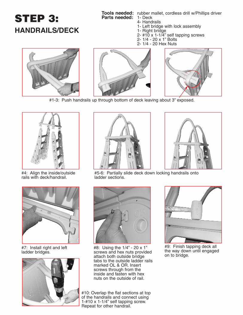
4- Handrails1- Left bridge with lock assembly1- Right bridge2- #10 x 1-1/4” self tapping screws2- 1/4 - 20 x 1” Bolts2- 1/4 - 20 Hex Nuts
#1-3: Push handrails up through bottom of deck leaving about 3” exposed.
#4: Align the inside/outsiderails with deck/handrail.
#5-6: Partially slide deck down locking handrails onto ladder sections.
#7: Install right and left ladder bridges.
#8: Using the 1/4” - 20 x 1”screws and hex nuts providedattach both outside bridgetabs to the outside ladder railsmarked OL & OR. Insertscrews through from theinside and fasten with hexnuts on the outside of rail.
#10: Overlap the flat sections at topof the handrails and connect using1-#10 x 1-1/4” self tapping screw.Repeat for other handrail.
#9: Finish tapping deck allthe way down until engagedon to bridge.
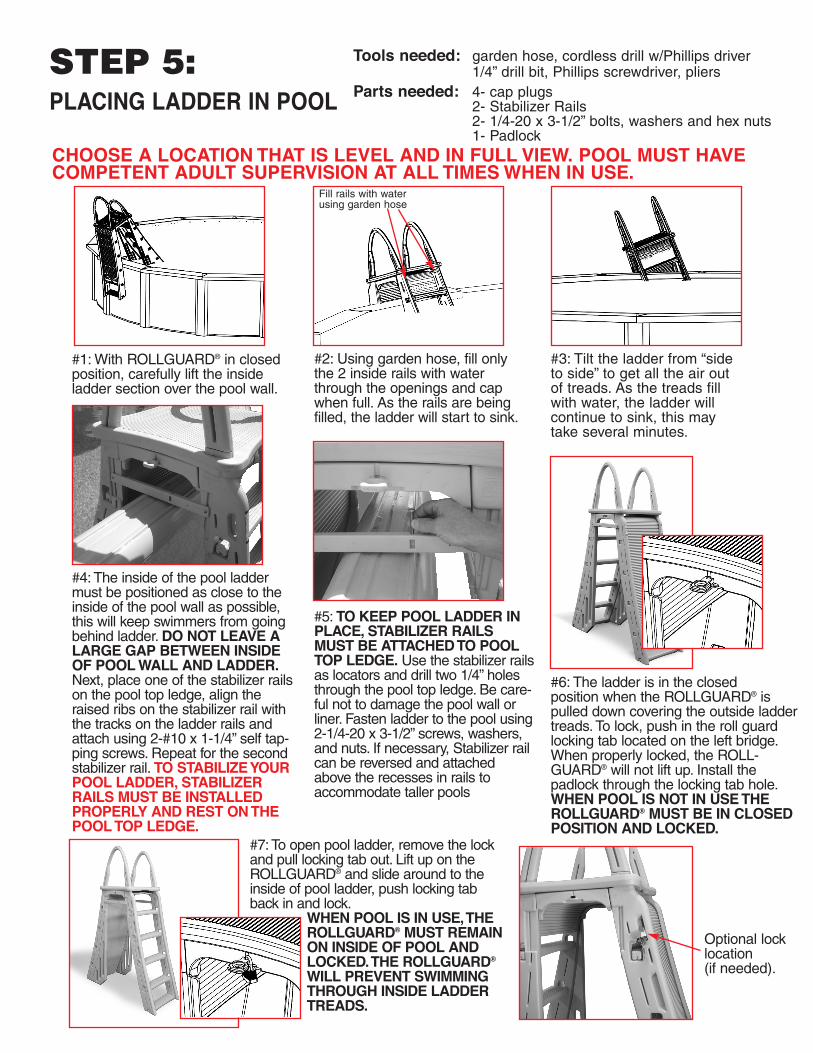
Parts needed: 4- cap plugs2- Stabilizer Rails2- 1/4-20 x 3-1/2” bolts, washers and hex nuts1- Padlock
CHOOSE A LOCATION THAT IS LEVEL AND IN FULL VIEW. POOL MUST HAVECOMPETENT ADULT SUPERVISION AT ALL TIMES WHEN IN USE.
#1: With ROLLGUARD® in closed position, carefully lift the inside ladder section over the pool wall.
#2: Using garden hose, fill onlythe 2 inside rails with waterthrough the openings and capwhen full. As the rails are beingfilled, the ladder will start to sink.
#3: Tilt the ladder from “sideto side” to get all the air outof treads. As the treads fillwith water, the ladder willcontinue to sink, this maytake several minutes.
#4: The inside of the pool laddermust be positioned as close to theinside of the pool wall as possible,this will keep swimmers from goingbehind ladder. DO NOT LEAVE ALARGE GAP BETWEEN INSIDEOF POOL WALL AND LADDER.Next, place one of the stabilizer railson the pool top ledge, align theraised ribs on the stabilizer rail withthe tracks on the ladder rails andattach using 2-#10 x 1-1/4” self tap-ping screws. Repeat for the secondstabilizer rail. TO STABILIZE YOURPOOL LADDER, STABILIZERRAILS MUST BE INSTALLEDPROPERLY AND REST ON THEPOOL TOP LEDGE.
#5: TO KEEP POOL LADDER INPLACE, STABILIZER RAILS MUST BE ATTACHED TO POOLTOP LEDGE. Use the stabilizer railsas locators and drill two 1/4” holesthrough the pool top ledge. Be care-ful not to damage the pool wall orliner. Fasten ladder to the pool using2-1/4-20 x 3-1/2” screws, washers,and nuts. If necessary, Stabilizer railcan be reversed and attachedabove the recesses in rails toaccommodate taller pools
#6: The ladder is in the closed position when the ROLLGUARD® ispulled down covering the outside laddertreads. To lock, push in the roll guardlocking tab located on the left bridge.When properly locked, the ROLL-GUARD® will not lift up. Install the padlock through the locking tab hole. WHEN POOL IS NOT IN USE THEROLLGUARD® MUST BE IN CLOSEDPOSITION AND LOCKED.
#7: To open pool ladder, remove the lockand pull locking tab out. Lift up on the ROLLGUARD® and slide around to theinside of pool ladder, push locking tabback in and lock.
WHEN POOL IS IN USE, THEROLLGUARD® MUST REMAINON INSIDE OF POOL ANDLOCKED. THE ROLLGUARD®
97 Witmer RoadNorth Tonawanda, New York 14120-2421Toll Free U.S./CANADA 800-635-3213716-694-3100ww.conferladders.com
Printed in U.S.A.
PROUDLY MADE IN THE U.S.A. by:
IMPORTANTFOR YOUR SAFETY
* Check the contents of the carton with the Parts listfor this ladder.
* If any parts are missing call Toll Free U.S./Canada - 800-635-3213 or visit our web site at: www.conferladders.com
* DO NOT attempt to assemble or install the ladder if there are ANY shortages of parts or hardware.
* For proper assembly and installation follow allinstructions in the sequence shown.
* Before using the product, after assembly and installation, go over the instructions and proceduresagain to make sure nothing has been overlooked.
* Be sure and safe. The manufacturer IS NOTresponsible for improper assembly, installation and use.
SAFETY RULES* Locate ladder on a solid base.* One person on the ladder at a time.* Ladder MUST be installed per manufacturer’s
instructions.* DANGER: No Jumping or Diving from ladder.* Face ladder when entering and leaving pool.* To prevent entrapment or drowning — DO NOT
swim through, behind or around ladder.* Ladder to be used as a swimming pool ladder only.* Weight limit - 300 lbs maximum* Warning: Exceeding the maximum weight
restriction may cause the ladder to fail.* When ladder is not in use pull down roll guard to
cover outside ladder treads and lock using padlock.* Consult your local Building Department before
installation of your pool and equipment.* DANGER: Use a cordless drill for assembly
and installation. NEVER use an electric drill in or around the pool.
s
sadderrd
ge.
e. ESED
MAINTENANCE: Check the padlock for proper operation and lubricate if necessary. When pool is not inuse ROLLGUARD®must be in closed position and locked.
WINTERIZING: Unfasten the ladder from pool top seat and remove from the water. Remove the plugs andlay ladder on its side to drain. It will take several minutes for the water to drain out of the ladder rails and treads.A small amount of water left in ladder will not cause any damage. Replace the plugs so they won’t get lost.
ock
d).
CONFER PLASTICS, INC. FIVE YEAR WARRANTYConfer Plastics, Inc. warrants their swimming pool ladders and steps to be free fromdefects in workmanship for five years from date of purchase.
DO NOT RETURN DEFECTIVE PART TO DEALERE-MAIL CONFER PLASTICS AT: [email protected]
A PICTURE [S] OF DEFECTIVE PART, A BRIEF DESCRIPTION OF PROBLEM, PROOF OF PURCHASE AND YOUR CONTACT INFORMATION.
INFORMATION MAY ALSO BE FAXED TO CONFER PLASTICS AT: 716-694-3102OR MAILED TO THE ADDRESS BELOW. UPON REVIEW OF THE INFORMATION YOU
WILL BE NOTIFIED IF PART IS COVERED UNDER THE WARRANTY AND THE SHIPPING/HANDLING CHARGES.
This warranty gives you specific legal rights, and you may also have other rights which may vary from state to state.