SHIMMABLE HARD STOPIF SHIMMING, WELKER RECOMMENDS 3mm, 5mm MAX.
HARD STOPS
Z(SAME FOR RAP & RIGID OPTION IN RAM
EXTEND POSITION, SHOWN)
ON SB SERIES SHOT PINS THE RAM EXTEND POSITION (DIM B + STROKE) IS THE SAME FOR RAP OR RIGID OPTION.REMOVAL OF RIGID COUPLER CONVERTS UNIT TO RAP OPTION. SEE WEBSITE FOR DATA SHEET AND VIDEO www.welkerproducts.com
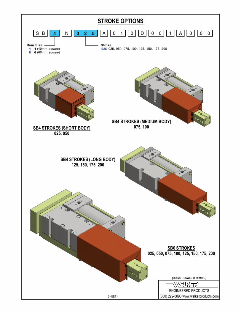
SB4 RAP OPTION SHORTENS RAM RETRACT BY 2mm. SB6 RAP OPTION SHORTENS RAM RETRACT BY 3mm
Ram Size Cylinder Options4 40mm square 01 Pneumatic Single Rod (NPT Ports)6 60mm square 02 Pneumatic Single Rod (G Ports)
Cylinder PositionSee Cylinder PositionChart A Below
Code
Cylinder & Port/Prox*
Location
A C1 & X1(SHN)
B C2 & X1
C C3 & X1
D C1 & X2
E C2 & X2
F C1 & X3
G C3 & X3
H C2 & X4
J C3 & X4
PORT
PROX
PR
OX
PR
OX
X1
63mm BORE100mm BORE
'G' (BSPP)
PROX
PORT
PO
RT
PO
RT 63mm &
100mm BORENPT PORTS
X1
ENGINEERED PRODUCTS
(800) 229-0890 www.welkerproducts.com
(DO NOT SCALE DRAWING)
SHEET 5
CYLINDER INFORMATION
C1
C2
C3
X1
X2
X3
X4
SEE DIAGRAMS BELOW FOR EXAMPLESOF PROX/PORTS OF ALL CYLINDERS
CHART A
For SB4 & SB6 (NPT Ports)Select the position of the cylinder (C1, C2 or C3)The X position for these cylinders is the PROX location,select this value (X1 thru X4).Find the preferred combination code in Chart A. For SB4 & SB6 (G Ports)Select the position of the cylinder (C1, C2 or C3)The X position for these cylinders is the AIR fitting location, select this value (X1 thru X4).Find the preferred combination code in Chart A.
NPT PORT CYLINDERSX1 OPTION DESIGNATES LOCATION OF THE
PROX*. TO ROTATE THE PROX LOCATION 90°CLOCKWISE, ORDER THE X2 OPTION, OTHER
ROTATIONS AVAILABLE (SEE CHART A).
CHART B
G PORT CYLINDERSX1 OPTION DESIGNATES LOCATION OF THEPORT. TO ROTATE THE PORT LOCATION 90°CLOCKWISE, ORDER THE X2 OPTION, OTHER
ROTATIONS AVAILABLE (SEE CHART A).
PORTSSEE CHARTS A & B& DIAGRAMS BELOW
PROX* MOUNTSEE CHART A FORLOCATIONAL OPTIONS
RECOMMENDED OPERATING PRESSUREPNEUMATIC: 60-80 PSI, FLOW CONTROLS NOT REQUIRED
UNIT Nominal Ram Pneumatic Bore Pneumatic Port Size Prox* Port Reed Depth
SB4 40 63 3/8" NPT or G3/8 26mm
SB6 60 100 1/2" NPT or G1/2 32mm
*NOTE: CYLINDICATOR
STYLE PROX SWITCHES ARE
NOT INCLUDED
Series
Nominal
Ram A B C D ØE ØF ØG ØH J K
SB4 40 25 15 15 30 9.0 11.0 8.0 THRU 8.0 THRU 25 M8 X 1.25 - 15 DEEP
SB6 60 25 15 15 30 9.0 11.0 8.0 X 16 DEEP 8.0 THRU 40 M10 X 1.5 - 20 DEEP
S B 4 N 0 2 5 A 0 1 0 D 0 0 1 A 0 0 0
Ram Size Ram Style4 40mm square D 4 Hole - Large6 60mm square L 4 Hole - Medium
ENGINEERED PRODUCTS
(800) 229-0890 www.welkerproducts.com
(DO NOT SCALE DRAWING)
SHEET 6
STANDARD RAM OPTIONS(See supplemental ram sheet for non-standard ram options)
J CENT
J CENT
4X K TAP
B
C
AD
4X Ø F THRU ~ RAM STYLE "D"
4X Ø E THRU ~ RAM STYLE "L"
4X Ø H P.F. DOWEL ~ RAM STYLE "D"
4X Ø G P.F. DOWEL ~ RAM STYLE "L"
ENGINEERED PRODUCTS
(800) 229-0890 www.welkerproducts.com
(DO NOT SCALE DRAWING)
SHEET 7
MOUNTED TOOLING MUST BE WITHIN APPROVED APPLICATION RADIUS FROM END OF RAM:100 lbf @ R = 150.0mm (6.0") 40 RAM250 lbf @ R = 200.0mm (8.0") 60 RAM
±0.13 (±.005") MAXDEFLECTION AT END OF RAMUP TO THE FOLLOWING STROKES:40mm RAM: 75mm STROKE60mm RAM: 100mm STROKE
Body Mounting: Square ram shot pin units have dual mounting capability. At all mounting locations, you have the option of mountingfrom the top using the counter-bored clearance holes or the same holes, tapped from the bottom. Using any four of the six holes, symmetrical about the centerline, is sufficient. Protruding mounting dowesl are provided and are press fit into the body. Square ram packages are high precision full contact plane bearing units and therefore must be mounted to a flat surface. Mounting surfaces must be flat within .002" (0.05mm). Ram Mounting: Square ram shot pin units use a standard NAAMS L-Block pattern with 15mm spacing. Spacing allows mounting of 3 and 4 hole pin retainers and L-blocks to the ram. Through holes can be tapped and fitted with standard thread inserts. Shrouds: Safety orange steel shrouds are available for additional protection. Shrouds prevent undesirable buildup of contamination from welding and machining applications. Welker specifically recommends shroud usage in MIG, TIG and arc welding applications. Shrouds should only be removed if clearance problems exist and conditions permit. Consult Welker. Wipers: The wiper is the only maintenance item on Welker pin units. It is a custom molded moly impregnated urethane wiper. Welkerrecommends changing the wiper yearly. Specific applications may require more or less frequent wiper service. Stroke: The stroke accuracy of shot pins is limited to that of the cylinder. Normal cylinder stroke accuracy is ± .015" (0.38mm). For control of "end of stroke" repeatability, see extend and retract stop options for each series. Rap couplings cause the unit to be less than the nominal stroke of the cylinder. The 40mm ram units have a 2mm rap. The 60mm ramunits have a 3mm rap. The rap allows the cylinder to begin moving before moving the ram. The impact of the coupler helps free tooling from a bound condition. Most applications using a pneumatic shot pin should have rap couplings. Rap coupler not available on hydraulic units. Welker cylinders do not require lubrication. Switch: 40mm ram tie rod cylinders use prox switch (cylindicator) ports with 1.025" read depth (probe length). 60mm ram tie rod cylinders have prox switch (cylindicator) ports with 1.250" read depth (probe length). Prox switches (cylindicators) are NOT included. Shot pins ordered with compact cylinders are cylinder switch ready. Cylinder switches are available though Welker. World switches are available through Welker for shot pins offering world switch capability. Repeatability: Shot pin units utilize a full contact bearing surface for high repeatability. Repeatability within ±.002" (0.05mm) part to part is achievable. Wear: Wear equals variance in position under load over time. Shot pin tests indicate maximum wear of .002" wear at 3 million cycles. Loading and Deflection: Maximum deflection is ±.005" and is measured at the end of the ram up to the specified strokes and up tothe loads and distances as shown below. Longer extensions can be used at lower tolerances and loads. Pins mounted closer to the body exhibit less deflection. For applications with longer strokes and higher loads, consult Welker.
WELKER SB SERIES SHOT PIN TECHNICAL INFORMATION
R
DD
MOUNTED TOOLING MUST BE WITHIN APPROVED APPLICATION DISTANCE FROM CENTER OF UNIT BODY AND END OF RAM:100 lbf @ D = 150.0mm (6.0") 40 RAM250 lbf @ D = 200.0mm (8.0") 60 RAM


![AY2 network cabinet · V]Reversible solid plate rear door with lock. V]Removable side panels with side pins, side locks are optional for protection. V]U marked mounting rail, width](https://static.documents.pub/doc/80x56/5ec4119ef80d663f5d1d4b2c/ay2-network-cabinet-vreversible-solid-plate-rear-door-with-lock-vremovable-side.jpg)


