ISOILI M P I A N T I ISOIL IMPIANTI spa – ItalySede e StabilimentoHead office and factory24061 Albano S. Alessandro (BG) 74, via Madonna delle RoseTel. +39 035 4239.011Fax +39 035 582078E-mail: [email protected]OPERATOR'S MANUAL SBM 75 P.D. METER ALUMINIUM EXECUTION Distributed by: "DAIS GLOBAL " LTD t+359 2 973 27 67 Site: http://daisglobal.eu/
Transcript
ISOIL�I M P I A N T I
ISOIL IMPIANTI spa – Italy�
Sede e Stabilimento�Head office and factory�24061 Albano S. Alessandro (BG)74, via Madonna delle Rose�Tel. +39 035 4239.011�Fax +39 035 582078�E-mail: [email protected]�
5 Special Tool .......................................................................................................... 12
6 Technical data ....................................................................................................... 13
OPTIONAL: Strainer air separator Preset valve + check Calibrating mechanism for mechanical counter Gearing box for electronic counter VEGA
Page 2 Isoil impianti S.p.A. Code MA/0026/00/EN/05 All rights reserved. Reproduction of this manual is forbidden
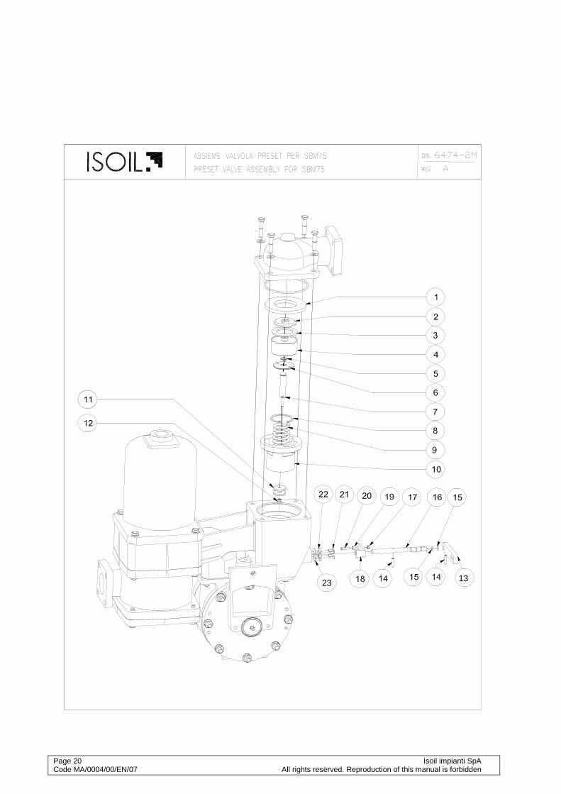
ENCLOSED: Overall dimensions with mechanical counter ......................................... Dwg.4251 Overall dimensions with EM6422 ...................................................... Dwg.5302-3 SBM75 P.D. meter assembly ........................................................... Dwg.6474-M SBM75 P.D. meter assembly with air vent valve ............................ Dwg.6474-1M Preset valve assembly ..................................................................... Dis.6474-2M Vane assembly ..................................................................................... Dwg.6063 Air vent valve ..................................................................................... Dwg.565-M Calibration mechanism ....................................................................... Dwg.672/75 Gearing box for mounting with VEGA counter ....................................... Dwg.3958
ISOIL IMPIANTI updates own products without condition of advance notice. ISOIL IMPIANTI doesn’t take liabilities for use the dates that are modified
Isoil impianti SpA Page 1 All rights reserved. Reproduction of this manual is forbidden. Code MA/0004/00/EN/07
1 Introduction
1.1 Warranty Instruments are guaranteed for twelve months for the date of delivery. Warranty cover only defective parts and faulty workmanship and doesn't cover defects due to wearing, dirt, modification and alteration of the instrument not authorized by Isoil Impianti SpA. Warranty is given free of charge ex our works. Warranty of instruments and accessories not manufactured by Isoil Impianti, will be covered by warranty of the sub supplier. Warranty is valid only if original spares are used and is invalidated in case of improper use or not following the technical specification of the instrument. Only Isoil Impianti SpA has the right to decide if the warranty can be applied. If the purchasing order calls for different warranty conditions, above stated conditions are surpassed.
1.2 Introduction ISOIL positive displacement meters are precision measuring instruments designed for use with a variety of petrochemical products and liquids. Each meter is fully tested and calibrated by factory before dispatch, and a regular service will maintain a high standard of performance and accuracy. P.D. meters must be periodically tested by a calibrating tank, Prover, or Master Meter: if out of accuracy a service is necessary. Experience has shown that mechanical defects are usually caused by the entry of foreign matters into the metering compartment due to inadequate straining facilities in the pipeline. Special tools have been designed to facilitate overhaul operations and their use is recommended.
1.3 Working principles Liquid enters the meter through the manifold and causes the rotor to revolve by pressure on the vanes. (fig.1) The proximity of the rotor to the front and rear of the casing forms an efficient seal while the profile of the casing guides the vanes on to the measuring crescent. The seal between vane and body is assured by the combined effects of gravity and centrifugal forces of vanes and it is assured the self-balance of clearances generated by the use too. The rotor spindle extends through a pressure tight seal in the meter front cover into the calibrating mechanism which transmits the rotor movement to the register.
Fig.1
Page 2 Isoil impianti SpA Code MA/0004/00/EN/07 All rights reserved. Reproduction of this manual is forbidden
CAUTION
All parts under pressure must be released before di sassembling the meter or its accessories for adjustment, inspec tion, servicing or substitution of its components. Also make sure that all electric or electronic part , if present, are disconnected from its power supply.
2 General safety principles This operator’s manual contains basic safety instructions that must be followed during system installation, operation and maintenance. Failure to comply with these instructions may result in personal injury and can lead to personal, industrial or environmental accidents. Some examples of possible hazards caused by non-compliance with these instructions are:
Failure of the system and/or some components. Hazards to people caused by the exposition to electrical, mechanical or chemical
influences. Pollution of the environment through the leaking of hazardous substances.
Therefore, follow the safety instructions described in this manual; in case of uncertainties, please contact the manufacturer.
2.1 General instructions Read carefully the operator’s manual. Make sure that all the personnel assigned to the installation, operation and
maintenance is properly trained. Make sure that the contents of the operator’s manual are completely understood by all
personnel assigned to the operations on the system. Inspect parts under pressure in compliance with national regulations before the initial
operation of the system. Make sure that the operator’s manual is readily available to personnel on site Follow national safety regulation in force in the location of the plant. Make sure that the system operates in compliance with the relevant operational limits. All pressure parts must be inspected and serviced in accordance with national laws in
force.
2.2 Meter operation The meter must be operated only by trained and authorized personnel. The meter must not be operated in presence of foreign, unauthorized or not
Isoil impianti S.p.A. Page 1 All rights reserved. Reproduction of this manual is forbidden. Code MA/0026/00/EN/05
adequately trained personnel. The meter must be used for the purpose it is made for; the manufacturer is not
responsible for any damage deriving from uses outside of the original purposes. The meter must be operated inside the limits fixed by the manufacturer; the
manufacturer is not responsible for any damage deriving from uses outside of the operational limits of the device.
2.3 Instructions for the operator The operator must adhere to safety and accident-prevention standards currently in
force in the country where the device is installed. The operator must not, by his own initiative, carry out any operation that is outside his
competence. The operator must carefully comply with hazard and/or prohibition instructions
contained in this manual. Do not use petrol, solvents or other flammable substances to clean parts. Use only
approved commercial solvents that are non-flammable and non-toxic.
2.4 Servicing instructions Read carefully the rating plates on the individual equipment Never carry out any maintenance, servicing or regulation before having closed the root
valve, discharged the pressure from the system and disconnected the power supply to any electrical device (if present), unless explicitly stated otherwise.
All maintenance operations, either ordinary or extraordinary, must be done by authorised and trained personnel
The maintenance operator must wear clothes adequate to the working environment and to the situation; in particular, loose or voluminous clothes, chains, bracelets, rings, earrings or anything that might get caught in the mechanical parts of the system should be avoided
The maintenance operator must wear adequate protective devices in accordance with safety and accident-prevention regulations
In explosive environments use only antisparking equipment If the meter is connected to any electric or electronic equipment, disconnect all of them
from the power supply before doing any servicing or regulation operation, unless explicitly stated otherwise in the manual
2.5 Operating precautions The meter must be calibrated following the instructions reported into the operator's
manual and in what stated into the Manual of Petroleum Measurement Standards (API) with particular attention to the following chapters:
Chapter 4: proving systems Chapter 5: metering Chapter 6: metering assemblies Chapter 11 section 2.3: water calibration of volumetric provers Chapter 12 section 2: calculation of petroleum quantities
The meter must always remain full of product; to achieve this, it is suggested to install the meter so that it remains below the main line.
The line upstream the meter must be kept full of product to avoid that some air enters the meter.
Each meter must be adjusted following the instructions supplied in the operator’s
Page 2 Isoil impianti SpA Code MA/0004/00/EN/07 All rights reserved. Reproduction of this manual is forbidden
manual. Follow the recommendations of the manufacturer when installing pumps. Pay particular
attention to factors such as the use of foot valves, inlet pipes dimension and conformity with NPSH when there are suction pumps. Follow the recommendations of the manufacturer to minimize the problems due to air and vapors.
For flashing liquids (quick gasification of the liquid) or easily vaporizing liquids at high environmental temperatures, e.g. light hydrocarbon, it is advisable the use of submerged aspirations and pipes larger than the nominal dimension of the pump.
Thermal expansions that generate overpressures can easily damage the meters and the systems in general. Put safety valves for overpressure in every section that can be closed through regulation or isolation valves.
Isoil impianti S.p.A. Page 3 All rights reserved. Reproduction of this manual is forbidden. Code MA/0026/00/EN/05
3 Installation
3.1 Precautions The installation of the meter counter does not require any special procedure; just pay attention to the following points:
• The meter counter must be installed horizontally; for other applications a vertical arrangement is provided. In both cases the rotor axis must be kept horizontal.
• All the meter’s openings are protected with covers when shipped; those must not be removed until the meter is installed on the piping
• Before the installation of the meter, it's suggested to clean thoroughly the piping to remove dirt, crusts and other foreign particles.
• Piping should not exercise strain on the meter. The meter is designed for overhang and supports should be provided only on the adjacent pipes.
• Leave space enough around the meter to ease access for adjustment, servicing and disassembly. The counter, if present, must be easily readable.
• The meter must always remain full of product; it's suggested to install the meter so that it remains always under the main line.
• The line upstream the meter must always remain full of product to avoid that air enters the meter's measure chamber; if the pipe arrangement allows reversal flow, a non-return valve must be installed.
• Flow through the meter must be regular and uniform; pulsating and irregular flows must be avoided.
• It is recommended to install flow limiting valves downstream of the meter if the flow rate can reach values higher than the maximum allowed for the meter.
• If the line pressure can reach values higher than the maximum allowed, automatic safety valves must be installed in adequate places.
• To protect meter from damages due to foreign particles in the liquid, a suitable strainer with a correct mesh number (40 mesh for oil, 60 mesh for diesel oil, 100 mesh for
Page 4 Isoil impianti SpA Code MA/0004/00/EN/07 All rights reserved. Reproduction of this manual is forbidden
gasoline) must be installed upstream the meter.
• In case the rate of flow through the installation exceeds the meter maximum rated capacity, it is advisable to use a flow limiting valve, which must be installed downstream the same meter.
• Water must not flow through the meter.
• Meters must be installed in such a way that air or vapour do not enter through the liquid under measurement. It is always suggested to install an air separator just upstream the meter.
• To avoid hammer shocks which may strongly damages the meter, it is not advisable to install upstream or downstream the meter any quick closing valves.
• It is recommended to install root valves at the inlet and outlet to ease servicing operations and isolation of the meter.
3.2 Start-up precautions • Before proceeding with the start-up make sure that:
- The meter is adequately fixed. - All the connections are tightened. - Air is bled from the pipes.
• If a calibration mechanism is associated with the meter, before the start-up it must be filled with lubricating oil.
• Vent out all the air eventually present in the line.
• When the meter is operated for the first time, fill it slowly with the operating fluid by following this procedure:
- Open slowly the upstream isolation meter or fill the meter by gravity. - Open slowly the downstream isolation meter letting the flow rate rise smoothly to
the operating value.
CAUTION
If the line pressure can reach values higher than t he maximum allowed, automatic safety valves must be installed in adequate places. It is necessary to avoid the pressure meter exceeds the maximum high pressure showed on the meter plate. Be very careful when starting up the meter: if the air enters the measuring chamber the rotor can easily reach high r otational speeds, leading to abnormal wear of the vanes and o ther components; this, in turn, will lead the meter to a major failure.
Isoil impianti S.p.A. Page 5 All rights reserved. Reproduction of this manual is forbidden. Code MA/0026/00/EN/05
CAUTION
All parts under pressure must be released before di sassembling the meter or its accessories for adjustment, inspec tion, servicing or substitution of its components. Also make sure that all electric or electronic part , if present, are disconnected from its power supply.
4 Maintenance Before removing the flow meter from the pipeline for repairs, it is recommended that the possible causes and corrective actions are noted with the help of Fault Diagnosis Chart given in this manual. Note that certain components in the flow meter assembly are not interchangeable. Therefore, if more that one flow meter is dismantled, it is recommended that each flow meter is dismantled independently.
CAUTION: Be very careful when you start up the meter after maintenance: if the air enters the measuring chamber the rotor can easily reach high rotational speeds, leading to abnormal wear of the vanes and other components; this, in turn, will lead the meter to a major failure. See chap.3.2 for start-up precautions.
4.1 Disassembly The flow meter may be considered as two main assemblies: the measuring chamber and the calibrating mechanism. To separate these two assemblies from each other, remove the screws securing the calibrating mechanism on the flow meter body.
CAUTION: Before dismantling the meter for maintenance release pressure from the line and drain all the fluid inside the meter through the draining hole below the meter.
Proceed then with the maintenance of the faulty part.
4.1.1 Main components disassembling 1. To ensure stability during the dismounting, it is advisable to use our "Ring Support tool"
(see special tool). 2. Remove the sealings and the screws of the counter, unscrew the screws fixing the
calibrating mechanism and after the removal of the transmission spindle, take off the transmission spindle pin.
3. Remove all nuts, bolts and washers of the front cover. 4. Remove the front cover using the "Cover Removal Tool" (see special tool).The shims
between cover and rotor are not interchangeable, they must be placed in their original position.
5. Remove the rotor group by using the "Rotor removal and turning tool" (see special tool).
Page 6 Isoil impianti SpA Code MA/0004/00/EN/07 All rights reserved. Reproduction of this manual is forbidden
6. Extract the rotor paying attention to use the free hand to guide the rotor and control the lateral vanes movement.
4.1.2 Rotor disassembling
NOTE: Never remove the vanes unless they are damaged. If it is necessary to remove the vanes, before proceeding mark the position of the four vanes that correspond with the position in the rotor: that will ease the reassambly procedure. Vanes are not interchangeable and, if they can be reused, they must be placed in their original position.
See dwg.6063 for disassembling the vanes
• Remove the split pin placed.
• Remove the vane.
• Remove the remaining vane-rods assembly.
CAUTION: Don't remove or loosen the the vanes adjusting nuts, since that would vary the clearance between the vanes and the measuring chamber, causing loss of performance and/or meter failure.
4.2 Assembly Before assembly, clean and inspect all parts for any visual damage. Ensure that all o-ring grooves are clean and undamaged. Examine the O-Rings and ensure that they are not damaged or swollen, replace them if necessary. Examine graphite bushes on rotor assembly for free rotation and play, replace them if either is apparent. Examine each vane assembly for damage or wear, replace vane(s) if either is apparent. Examine gland seal rings in rotor assembly for damage or wear and replace if either is apparent. The assembly procedure is the reversal of the dismantling procedure; only for installation of the internal body special precautions should be taken to match the centering cap of the external body's front cover.
4.3 Calibrating mechanism (only for mechanical counter)
The calibrating mechanism comprises a train of gears which transmit movement of the rotor to the counter. Operational failures of the mechanism are rare and they generally regard the breaking of tension pin, due to an excessive strain. (see dwg.672) It is recommended to repair without varying the calibrating adjustment.
CAUTION: do not remove the shimming washers between the frame and the bearing of the mechanism box.
• For p.d.meter with bush for pulse emitter, use the special tool, screw it in the hole (Fig.2)
• For p.d.meter with shaft use the superior part of the tool; to block the tool to the rotor shaft with a pin 2mm diam. (Fig.1)
Fig.1 Fig.2
Isoil impianti S.p.A. Page 7 All rights reserved. Reproduction of this manual is forbidden. Code MA/0026/00/EN/05
This chapter only applies for mechanical counter; for the calibration of the meters with electronic counter please refer to the specific manual.
4.3.1 Calibration of flow meter To carry out meter calibration follow next procedures (see Fig.2): a) Remuve the plug (8) under the housing (1) and drain the oil; b) Break and remove seals (10) to the cover (11); c) Remove the three screws (9) securing the cover to the housing (1) in which calibrating
mechanism is fitted (7); d) Remove cover (11); e) By using square key (4 mm) (5) turn shaft (6) till the holes placed (3a -3b-3c) (Fig.2a)on
the bracket (2) and on friction roller will be properly aligned; f) Insert in this hole (3) the stop pin (4) then using the square key (5) operate on the shaft
(6) as follow: turning counter-clockwise direction, even if the quantity of fluid does not vary, on the
counter is obtained an higher volume indication; turning clockwise direction it is obtained a lesser indication
g) Put the cover (11) back to the housing, screw the screws (9) and set the seals (10); fill the housing with lub oil (see cap. 4.4)
The square key (5) and l the stop pin (4) are always supplied whether the p.d.meter has a mechanical counter.
NOTE: one complete turn of the screw (6) varies the volume indicated on the meter by approximately 0,18% (per cent).
Fig.2
2
6
8
7
4
5
3
1
9
10
11
4 3a 3b 3c
2
Fig.2a
Page 8 Isoil impianti SpA Code MA/0004/00/EN/07 All rights reserved. Reproduction of this manual is forbidden
4.4 Suggested lubricating oil for calibrating mechanism
To allow proper lubrication of the gear wheels on the housing is essential to fill the box with lubricating oil, using the black plug on the side of the box. Make sure that the level oil upper the sight glass. In the Table 1 you can choose the lubricating oil if you know the using temperature The oil is suggested by ISOIL, for standard application is SAE10, for a range temperature (from –10° to +60°C); to avoid ice forming in win tertime, add two spoons of car antifreeze.
4.5 Tests after overhaul After overhaul the p.d. meters must be tested with suitable proving systems. Error between the value stated by the p.d.meter counter and the value stated by the proving device is calculated as below: Example: Measured by the meter Measured by the proving tank Error (%) 1000 l 1003 l -0,3% 1000 l 997 l +0,3% The formula is:
100%0
0 ⋅−=V
VVE
V= Measured by the meter V0= Measured by the proving tank
Oli consigliati al variare delle temperature estern e
-60 -40 -20 0 20 40 60 80 100 120 140
SAE 0W
SAE 10W
SAE 10
SAE 10W-40
SAE 15W-40
SAE 10W-60
SAE 5W-30
SAE 0W-30
T°C
Isoil impianti S.p.A. Page 9 All rights reserved. Reproduction of this manual is forbidden. Code MA/0026/00/EN/05
4.6 Strainer/air separator
4.6.1 Strainer A clean strainer is fundamental for the correct operation of the system; a dirt strainer would create an excessive pressure drop, leading to the failure of the basket and thus letting dirt, crusts and other harmful elements to flow into the fluid. If possible, check regularly the pressure drop between the inlet and the outlet of the strainer; the maximum allowed pressure drop is 130 kPa. For a correct servicing of the basket, follow the procedure described below (dwg6474/1M):
• Discharge the pressure from the system and close the valves at the inlet and outlet
• Discharge the liquid inside the strainer air separator through the draining outlet on the bottom of the strainer
• Remove the cap
• Remove the basket and clean it thoroughly with a jet directed from inside to the outside; if possible, use a water cleaning machine
• Check accurately that the gasket is intact; if it is found to be damaged, replace with another one with the same filtering grade:
For oils with viscosity up to 20°E(150cSt): 40 mesh (433 micron) For diesel oils: 60 mesh (247 micron) For gasoline or water: 100 mesh (153 micron)
• Put again the wire gauze in place, close the cover and the drain valve. It's suggested to replace the gaskets between the strainer body and the cover each time the strainer air separator is disassembled.
4.6.2 Air vent valve Follow the istructions below for the servicing of the air vent valve:
• Discharge the pressure from the system and close the valves at the inlet and outlet
• Discharge the liquid inside the strainer air separator through the draining outlet
• Inspect the air vent valve, checking that it works properly and its part aren't damaged
• Close the draining valve and restore the operating conditions
4.7 Extraordinary maintenance The user must define a maintenance scheduling table according to the fluid utilised, the operational conditions, the estimated/real workloads and the environmental conditions. For all extraordinary maintenance needed after a failure and/or the rising of a fault that compromises the normal operation of the system, please contact Isoil Impianti SpA Customer Care.
4.8 Storing if after a working period it is foreseen to stop the meter for a long time, drain the meter
and its accessories; If the meter or the equipment of the system are not immediately used, or if it is
withdrawn from service and stored, it is important to follow next instructions : fill the meter and its accessories with clean kerosene or lubricated oil and close its
Page 10 Isoil impianti SpA Code MA/0004/00/EN/07 All rights reserved. Reproduction of this manual is forbidden
ends with blind flanges; fill the carter containing the calibrating mechanism with oil till the sight glass is
reached adequately protect counters against rain and dust, with damp-proof caps
4.9 Spare parts For a correct meter maintenance use only original spare parts from Isoil Impianti S.p.A. . Isoil Impianti S.p.A. is not responsible for any problem that can result from the use of non original spare parts.
Page 12 Isoil impianti SpA Code MA/0004/00/EN/07 All rights reserved. Reproduction of this manual is forbidden
5 Special Tool DESCRIPTION USE FIGURE
Rotor removal and turning tool. Code 80AT0039
For removal and turning rotor
Cover removal tool (n.2 pieces are necessary) Code 80AT0042
For extracting front cover. B
Bearings extractor
Code 80ES0015
For dismounting the internal ring of the bearing after having broken the external ring.
C
Isoil impianti S.p.A. Page 13 All rights reserved. Reproduction of this manual is forbidden. Code MA/0026/00/EN/05
6 Technical data • Maximum working pressure ................................................................................ 1000 kPa
• Working temperature ................................................................................... -10°C ÷ +50°C
• Maximum flow rate ................................................................................................. 500 lpm The value reproduced in label can change as regards to those shown in the manual
Page 14 Isoil impianti SpA Code MA/0004/00/EN/07 All rights reserved. Reproduction of this manual is forbidden
Isoil impianti S.p.A. Page 15 All rights reserved. Reproduction of this manual is forbidden. Code MA/0026/00/EN/05
1
1
2
2
3
3
4
4
5
5
6
6
A A
B B
C C
D D
// /
67 90
67
90
Ø11
FLANGE QUADRE PN50DN50 SQUARE FLANGES
~295
509
191
384
100
SPAZIO PER ESTRAZIONE CESTO FILTROCLEARANCE FOR BASKET STRAINER REMOVAL
554
Page 16
Isoil impianti S
pA
Code M
A/0004/00/E
N/07
All rights reserved. R
eproduction of this manual is forbidden
DIS.
FOGLIO1 DI 1
6474-MASSIEME CONTATORE VOLUMETRICO SBM75
SBM75 P.D.METER ASSEMBLY
6
8
9 10 11 12 13 20 14 22 15 17 17 13 15 7 24 19
9
8
22
7 24
18
16
26
3
Isoil impianti S.p.A. Page 17 All rights reserved. Reproduction of this manual is forbidden. Code MA/0026/00/EN/05