..........................................................................GETTING STARTED WITH THE SBS-3 5
CONNECTING THE SBS-3 TO YOUR PC USING ...................................................................USB 5CONNECTING THE SBS-3 USING ETHERNET ............................................................................ 5SBS-3 FRONT PANEL LED INDICATORS DESCRIPTION................................................................ 6SBS-3 REAR PANEL CONNECTIONS...................................................................................... 7
.......................................................................................USING THE SDR RECEIVERS 8
WHAT IS SOFTWARE DEFINED RADIO .................................................................................? 8INTRODUCTION TO SDR ON THE ................................................................................SBS-3 8USING THE SDR CONTROL PANEL........................................................................................ 9CONTROLLING THE TUNERS ............................................................................................... 9CONTROLLING THE SDR CHANNELS .................................................................................... 10AN EXAMPLE OF USING THE SDR’S..................................................................................... 11USING THE AUDIO MIXER................................................................................................ 12
..........................................CONFIGURING ETHERNET PARAMETERS FOR THE SBS-3 14
SBS-3 Supplement to BaseStation Reference Manual Page 3 / 15
BaseStation is a Windows application written originally for the SBS-1 family of Virtual Radar Receivers. The latest version (1.2.3.164) is also compatible with the SBS-3.
This document is a supplement to the BaseStation Reference Manual. It describes the additional features available with the SBS-3, such as the Software Defined Radio (SDR) receivers.
1.2. Document Conventions A paragraph with this symbol contains a handy tip that will help you
use the product more efficiently.
A paragraph with this symbol contains an important point that you need to understand.
A paragraph with this symbol warns you about possible problems you might encounter.
1.3. Further InformationA useful source of further information can be found at the Kinetic Avionics Forum:
www.kinetic.co.uk/forums
Accessories may be purchased from:
www.kinetic.co.uk/estore
SBS-3 Supplement to BaseStation Reference Manual Page 4 / 15
2.1. Connecting the SBS-3 to your PC using USBThe simplest way to get started with your SBS-3 is to connect it to your PC using a USB cable, attach the 1090 MHz antenna, and install the BaseStation software following the procedure described in the Getting Started notes that accompany the BaseStation CD-ROM. The various chapters in the BaseStation Reference Manual describe how to view aircraft on a Virtual Radar Display.
The SBS-3 requires approximately 900 mA of current from the USB port when both SDR’s are turned on. Some PC’s, particularly older ones may not be able to supply this amount of power on a USB port. In this case, a special Y cable may be used to connect to either a second USB port on the PC, or an external power supply. One arm of the Y cable carries power only, and the other carries both power and data.
When receiving 1090 MHz radar data only, the SBS-3 uses less power and can be powered from any USB port.
2.2. Connecting the SBS-3 using EthernetConnecting via Ethernet requires more configuration but can offer greater flexibility, for example allowing connection to the SBS-3 over long distances. You will need to refer to the section below on Configuring Ethernet parameters for the SBS-3.
When connecting via Ethernet you can also use the SBS-3 as a stand alone data server. A remote device can open a TCP socket connection to the SBS-3’s main port and receive data without the requirement to log in or run BaseStation.
The SBS-3 always needs to be powered using the USB socket. If you are going to connect via Ethernet rather than USB, you will need to attach an external USB power supply. You should ensure that the external supply is rated at 1.0 Amp (1000 mA) or greater. When the USB port on the SBS-3 is connected to a PC (and the orange USB light is on indicating a USB data connection), the Ethernet interface on the SBS-3 is automatically turned off to save power. Therefore you cannot connect using Ethernet if the SBS-3 is connected via a USB cable to a PC.
SBS-3 Supplement to BaseStation Reference Manual Page 5 / 15
From left to right, the connections at the rear of the SBS-3 are:
1090 MHz Antenna. Used to connect the supplied magnetic mount antenna or other 1090 MHz antenna for receiving aircraft radar signals.
SDR antenna connection. Used for connecting an antenna for the two built-in SDR receivers.
Audio out. A 3.5 mm stereo audio jack socket for use with external speakers or headphones. It may also be connected to the audio line input of a PC or sound card.
Ethernet. Used to connect the SBS-3 to a PC or network.
USB. Can be used to connect the SBS-3 to a PC.
Aux Connector. An I2C bus and RS-232 connector for use with future accessories.
SBS-3 Supplement to BaseStation Reference Manual Page 7 / 15
3.1. What is Software Defined Radio ?With Software Defined Radio (SDR), instead of using dedicated hardware to allow reception of say AM or FM radio stations, the incoming radio signal is digitised and then processed in real time by software to extract the desired audio or data. This means that different features or types of processing can be added with out needing to change the hardware.
3.2. Introduction to SDR on the SBS-3The SBS-3 has two Software Defined Radio (SDR) tuners, called tuner A and B.
Each of these digital tuners can receive a continuous frequency span (bandwidth) of 8 MHz.
The centre frequency of each tuner’s frequency span can be set anywhere within the range 27 MHz to 980 MHz, and they may overlap.
There are then four independent SDR demodulator channels within the SBS-3, called SDR 1, 2, 3 and 4, which can process the digitised data from the two tuners. This allows up to 4 stations to be “picked out” simultaneously from the two 8 MHz tuner spans.
Each SDR channel can be tuned to any frequency within the tuned span of either tuner A or B. The demodulation type for each channel can be set independently to AM or FM. These demodulate the narrow band transmissions typically used in the aircraft, marine and other communications bands. SDR Channel 1 can also be set to Wideband FM mode for receiving FM broadcast radio transmissions, or the sound channels of analog terrestrial TV.
In the future it is expected that other types of demodulation will be supported, allowing for example ACARS or AIS data to be decoded.
Because it incorporates true SDR, the SBS-3 has no restrictions to the types of demodulator that can be implemented, or number of channels that can be received, other than the practical limits set by the hardware resources in the FPGA.
Kinetic may in the future offer different firmware sets allowing various combinations of features (such as number of channels and demodulators) to suit particular environments.
SBS-3 Supplement to BaseStation Reference Manual Page 8 / 15
3.3. Using the SDR Control PanelThe SDR features are accessed by a Control Panel. This is a separate window within BaseStation that can be launched either by using the “Built-In Radio” - “Control Panel” menu item, or by clicking on the Control Panel toolbar button, which is the leftmost button on the built-in radio toolbar:
If the Built in Radio toolbar is not visible, it can be enabled by using the “Settings” - “Toolbars” menu.
3.3.1. Controlling the Tuners
The top part of the SDR control panel concerns the two tuners, A and B. There is a frequency display for each tuner, and below the two displays there is a slider bar.
Each tuner can be turned on or off using the buttons on the left side of the corresponding panel. Initially they will both be turned off and the frequency display will show “Off”.
Once a tuner has been turned on, its centre frequency can be set and will be displayed in the corresponding tuner panel. This frequency can be set using either the slider bar or a pop-out keyboard.
The slider bar can be used as a coarse control to set the centre frequency for the currently selected tuner. This is the tuner whose frequency is shown in bright green (Tuner B in the example screen shot).
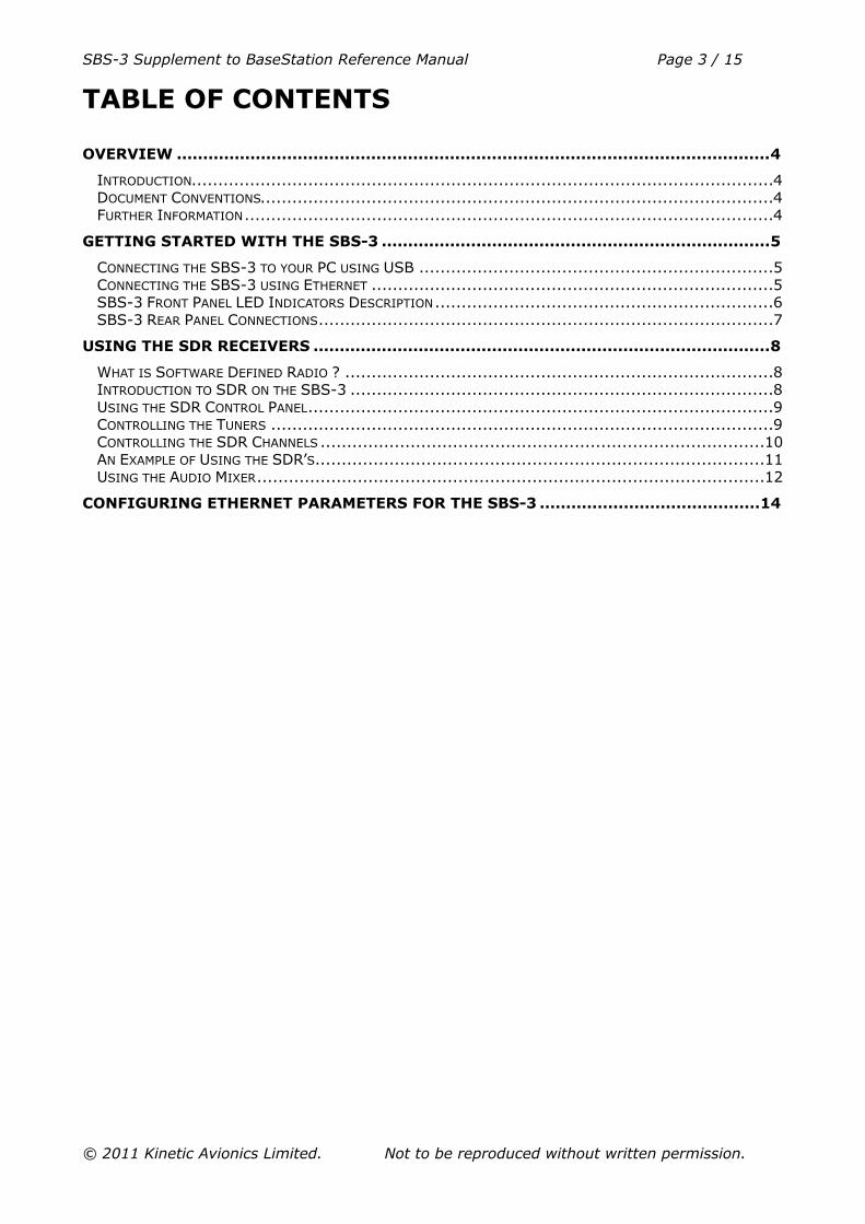
Alternatively you can enter a frequency using a pop-up keypad. To bring up the keypad, click on the “>” key at the right of the tuner display for which you wish to enter the frequency. Clicking on the “>” key again hides the keypad, or you can click on the “>” key for a different tuner, and the keypad will move to that tuner.
SBS-3 Supplement to BaseStation Reference Manual Page 9 / 15
Click on the keys (or use the PC’s keyboard) to enter the required frequency and then press Enter.
Remember, each tuner can capture an 8 MHz band within the radio spectrum. So for example if you are interested in some stations in the lower part of the aviation AM voice band, you could tune the centre frequency of one of the tuners to 122 MHz and that would enable you to receive channels between 118 and 126 MHz.
As another example, selecting a centre frequency of 160 MHz would cover the international marine FM band, between 156 and 164 MHz.
The centre frequency for each tuner must be within the range 27 MHz to 980 MHz. If you set a frequency outside this range, the frequency display will change to red.
The Automatic Gain Control (AGC) display for each tuner shows the current amount of signal attenuation within each tuner. This is displayed in units of decibels (dB). A value of 0 means no attenuation. The reason for attenuating the signal is if there is a strong transmission within or near that tuner’s frequency span that would otherwise overload the tuner or the analog to digital converter.
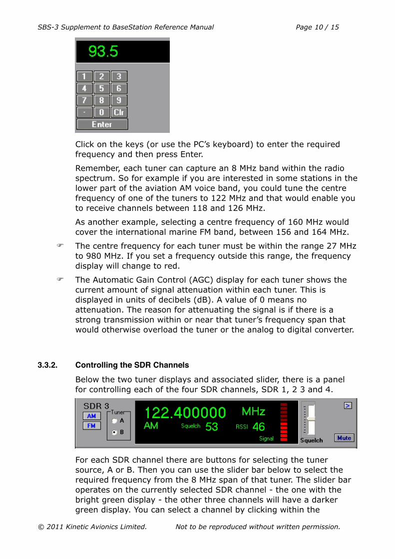
3.3.2. Controlling the SDR Channels
Below the two tuner displays and associated slider, there is a panel for controlling each of the four SDR channels, SDR 1, 2 3 and 4.
For each SDR channel there are buttons for selecting the tuner source, A or B. Then you can use the slider bar below to select the required frequency from the 8 MHz span of that tuner. The slider bar operates on the currently selected SDR channel - the one with the bright green display - the other three channels will have a darker green display. You can select a channel by clicking within the
SBS-3 Supplement to BaseStation Reference Manual Page 10 / 15
corresponding panel. The end points of the slider bar will change according to span of the selected tuner.
Alternatively as before, you can bring up the pop-up keypad to enter a frequency, by clicking on the “>” button at the right of the SDR panel.
These channels may be placed anywhere within the 8MHz spans of either tuner A or tuner B or both.
If you set a frequency outside this range, i.e. more than 4MHz away from the centre frequency of the tuner, the SDR channel’s frequency display will change to red.
As well as the frequency, you can set the modulation type for the SDR channel, AM or FM. Just click on the corresponding button at the left of the panel.
SDR1 also has WFM, allowing listening to broadcast FM and the sound channels of terrestial analog TV, etc.
For each SDR channel the Received Signal Strength Indication (RSSI) is displayed. This is a number indicating the relative strength of the radio signal being received on that channel. A difference of one in the displayed number represents a difference of approximately 1dB in the received signal power. At the same time, a bar indicator to the right gives a rough visual indication of signal strength.
There is also a slider control to adjust the squelch.
When squelch is active, the colour of the signal strength indicator bar changes to red.
You should adjust the squelch level so that the output is squelched (muted) when no transmission is taking place, so that you do not hear continuous noise in the background. When the RSSI increases above the set squelch level, the audio will be un-muted automatically.
Finally, there is an individual mute button for each SDR channel. As a reminder, a red “Mute” indication is displayed when the channel is muted.
3.3.3. An Example of Using the SDRʼs
You want to listen to London Volmet on 128.6 MHz and Gatwick Radar on 126.825 MHz, and also to two FM marine channels on 156.7 MHz and 161.3 MHz.
You can do this because the four frequencies fall within two 8MHz bands.
At the top of the control panel stack, you could set the centre frequency of tuner A to 127MHz. This gives tuner A a range of 123MHz to 131MHz. Then you can set SDR 1 to 128.6 MHz AM, and SDR 2 to 126.825 MHz AM.
SBS-3 Supplement to BaseStation Reference Manual Page 11 / 15
Now set the centre frequency of tuner B to 160MHz. This gives tuner B a range of 156MHz to 164MHz which spans the international marine band. Then set SDR3 to 156.7 MHz FM, and SDR4 to 161.3 MHz FM.
The audio mixer panel is then set to enable these SDRs on the left and/or right channel as required (see the Audio Mixer section).
Finally don’t forget to set the squelch levels for each SDR channel as required using the slider bars.
3.3.4. Using the Audio Mixer
At the bottom of the control panel stack, below the tuner and SDR controls there are two comprehensive audio mixer panels. The left hand panel controls the analog outputs (the standard 3.5 mm stereo audio jack socket located on the rear of the SBS-3). You can listen to this output using external speakers or headphones.
The right panel is for the digital output stream (transmitted to your PC or other equipment over USB or Ethernet). You can listen to this using a media player application. Refer to the section in the BaseStation manual on Digital Audio Streaming.
On the left of each mixer panel, there is an overall master gain (volume) slider control for the output, with the topmost setting being the maximum.
Below this are master check-box controls for the left and right output channels. Checking a box enables the output, unchecking it mutes the output.
To the right are controls that select which of the SDR channels are combined to generate the audio output. If a box is checked, then that channel’s audio is enabled.
You can enable the left and right channels separately, so that for example you could listen to one SDR channel (or combination of channels) in your left ear and another in your right ear.
You can also adjust the relative gain (volume) for each SDR using the slider controls. For example a channel with infrequent transmissions
SBS-3 Supplement to BaseStation Reference Manual Page 12 / 15
The Ethernet settings for the SBS-3 (including its IP address and port numbers) are stored in its internal non-volatile memory. These settings can be inspected and changed using BaseStation.
With BaseStation connected to the SBS-3 either by USB or by Ethernet, select the “Non-Volatile Memory Settings” option from the “Settings” menu. The following screen should be displayed:
The IP address is set to a default value of 192.168.1.170 when the SBS-3 unit is shipped. You may need to change this if your PC’s LAN uses an address range other than 192.168.1.xxx.
If you change the IP address on the SBS-3 box, you should also change the BaseStation settings for Ethernet under “Settings” – “Hardware” – “Network”, so that BaseStation can reconnect to the SBS-3.
SBS-3 Supplement to BaseStation Reference Manual Page 14 / 15
The Subnet Mask setting depends on the address size of the local network. Typically, for 192.168.x.x networks, it is normally set to 255.255.255.0.
The Gateway address is normally set to the IP address of your local router.
The Main Port value sets the TCP port number used by BaseStation or other application to communicate with and receive data from the SBS-3. The default port number used by the SBS-3 and BaseStation is 10001. You may need to change the port number to another value to be able to work with a particular application.
If you change the Main Port setting on the SBS-3 box, you should also change the port number in the BaseStation settings under “Settings” – Hardware – Network, so that BaseStation can reconnect to the SBS-3.
The NMEA Port is reserved for specifying the port for output of NMEA data. This will be used to output AIS marine data.
The Speed setting sets the speed of the Ethernet interface on the SBS-3. It can be set either to 10 M bit/sec or to 100 M bit/sec. This setting is ignored if Auto Negotiation is turned on.
The Full Duplex checkbox sets Full Duplex mode for the Ethernet interface (the default). This setting is ignored if Auto Negotiation is turned on.
The Auto Negotiate checkbox turns on negotiation of connection speed etc. between the SBS-3 Ethernet port and the device it is connected to (e.g. PC, router or Ethernet switch). Auto negotiation is on by default. It can be turned off where there are specific problems with this. In this case the Speed and Duplex mode should be selected manually.
SBS-3 Supplement to BaseStation Reference Manual Page 15 / 15