129
40025322 No.E364-01 ENGINEER’S MANUAL SC-510 ®
40025322No.E364-01
ENGINEER’S MANUAL
SC-510
®

PREFACEThis Engineer’s Manual is written for the technical personnel who are responsible for the service and maintenance
of the machine.
The Instruction Manual for these machines intended for the maintenance personnel and operators at an apparel
factory contains operating instructions in detail. And this manual describes “Standard Adjustment”, Adjustment
Procedures”, “Results of Improper Adjustment”, and other important information which are not covered in the
Instruction Manual.
It is advisable to use the instruction Manuals and Parts Lists for SC-510/M51, IP-100E/SC-510, and CP-160C
together with this Engineer’s Manual when performing maintenance of these machines.
This manual gives the “Standard Adjustment” on the former page under which the most basic adjustment value is
described and on the latter page the “Results of Improper Adjustment” under which stitching errors and troubles
arising from mechanical failures and “How To Adjust” are described.

Electric shock danger label
This label indicates thatthere is a danger of electricshock in the cover on whichthe label is pasted.
SAFETY DEVICE
Safety devices described below vary in accordance with the destination and specifications.
Motor pulley cover
Cover to prevent motorpulley and V belt fromcoming in contact witheach other.
Roll-in prevention pin
Pin to prevent roll-in by Vbelt.
Motor fan cover
Cover to prevent motor fanfrom coming in contact withother components.
Electric shock danger label
This label indicates thatthere is a danger of elec-tric shock in the cover onwhich the label is pasted.
Power voltage danger label
Cautions for usable powervoltage are described.
Power connector cover
Cover to prevent connec-tors from electric shockdue to high voltage sec-tion.

CONTENTS
1. SPECIFICATIONS....................................................................................................1(1) SC-510/M51 ............................................................................................................................................... 1
(2) Extension p.c.b. * (packed together with IP-100E) ..................................................................................... 1
2. OUTLINE ..................................................................................................................1(1) Features ..................................................................................................................................................... 1
3. CONFIGURATION ....................................................................................................2(1) SC-510/M51 ............................................................................................................................................... 2
4. EXPLANATION OF OPTIONAL CONTROL PANEL ...............................................3(1) List of control panel of CP-160 ................................................................................................................... 3
(2) Explanation of control panel CP-160 .......................................................................................................... 4
(3) Example of application ............................................................................................................................... 5
(4) IP-100E operation panel ............................................................................................................................. 6
(5) How to operate sewing patterns with IP-100E ............................................................................................ 8
(6) IP-100E information mode ........................................................................................................................ 13
(7) Software upgrade ..................................................................................................................................... 47
5. CONTROL BOX (SC-510) .....................................................................................50(1) Arrangement of connectors ...................................................................................................................... 50
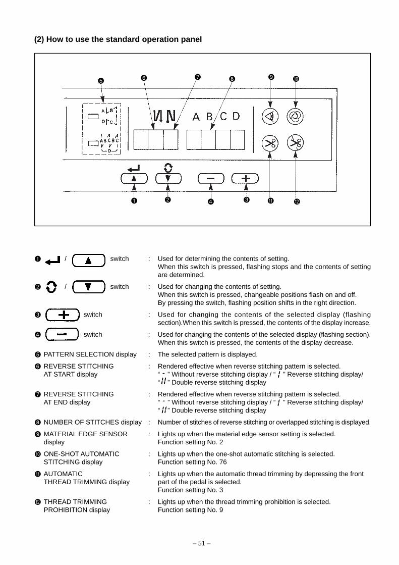
(2) How to use the standard operation panel ................................................................................................. 51
(3) Setting for functions of SC-510 ................................................................................................................. 56
(4) Function setting list (Start level ; U : User’s mode, S : Service mode) ..................................................... 58
(5) Detailed explanation of selection of functions .......................................................................................... 64
(6) Automatic compensation of neutral point of the pedal sensor .................................................................. 80
(7) Initialization of the setting data ................................................................................................................. 80
(8) How to select sewing machine head ........................................................................................................ 81
6. CHANGING PROCEDURE OF THE PEDAL TYPE ............................................. 83
7. CONNECTING PROCEDURE WITH JUKI OPTIONAL DEVICE ..........................84(1) Connection of the pedal of standing-work machine .................................................................................. 84
(2) Setting of the auto lifter function ............................................................................................................... 84
(3) Connecting procedure of CP-160 ............................................................................................................. 85
(4) Installation IPOP circuit board .................................................................................................................. 85
(5) Installation of IP-100E .............................................................................................................................. 85
8. EXTERNAL INPUT/OUTPUT CONNECTOR
(SIGNAL CONNECTOR FOR EXTENSION) .........................................................86(1) Encoder output connector (CN40) ............................................................................................................ 86
(2) Optional input/output connectors (CN50 and CN51) ................................................................................ 86
(3) Setting between IPOP board input/output connectors and jumper ........................................................... 87
(4) How to crimp the optonal connector ......................................................................................................... 91

9. HOW TO USE THE SIMPLIFIED PROGRAM FUNCTION ....................................93(1) Simplified program function ...................................................................................................................... 93
(2) Sequence of start and input ...................................................................................................................... 94
(3) Command input ........................................................................................................................................ 95
(4) Simplified program command list ............................................................................................................. 97
(5) Simplified program information input setting code list and connector location list .................................... 99
(6) Setting procedure of optional power and setting procedure of jumper for input changeover ................. 101
(7) Transition (sequence) diagram of No. 66 simplified program function ................................................... 105
10. CONNECTOR CONNECTION DIAGRAM..........................................................109(1) Solenoid for machine head ..................................................................................................................... 109
(2) Solenoid Connector for lifting presser foot ............................................................................................. 109
(3) Optional cord .......................................................................................................................................... 110
11. MAINTENANCE ..................................................................................................112(1) Replacing the fuse .................................................................................................................................. 112
(2) Changing procedure between 100V to 120V and 200V to 240V ............................................................ 114
(3) Control voltage check terminal of CTL circuit board ............................................................................... 115
12. ERROR CODES. ................................................................................................ 116(1) Error code list ......................................................................................................................................... 117
(2) IP-100E operation panel disply ............................................................................................................... 119
<REFERENCE> TABLE OF DIGITAL DISPLAY ......................................................120
13. BLOCK DIAGRAM. ............................................................................................121
14. INPUT/OUTPUT CHART ....................................................................................122

MEMO
– 1 –
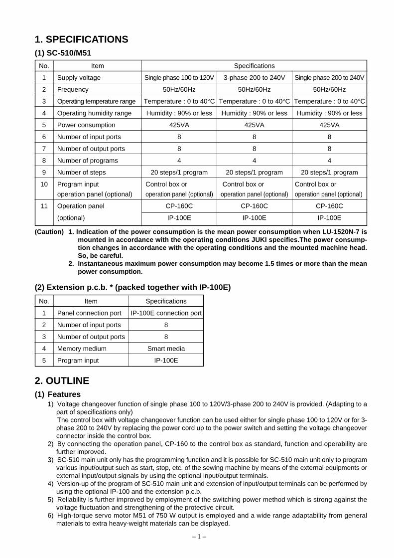
1. SPECIFICATIONS(1) SC-510/M51
No. Item Specifications
1 Supply voltage Single phase 100 to 120V 3-phase 200 to 240V Single phase 200 to 240V
2 Frequency 50Hz/60Hz 50Hz/60Hz 50Hz/60Hz
3 Operating temperature range Temperature : 0 to 40°C Temperature : 0 to 40°C Temperature : 0 to 40°C
4 Operating humidity range Humidity : 90% or less Humidity : 90% or less Humidity : 90% or less
5 Power consumption 425VA 425VA 425VA
6 Number of input ports 8 8 8
7 Number of output ports 8 8 8
8 Number of programs 4 4 4
9 Number of steps 20 steps/1 program 20 steps/1 program 20 steps/1 program
10 Program input Control box or Control box or Control box or
operation panel (optional) operation panel (optional) operation panel (optional) operation panel (optional)
11 Operation panel CP-160C CP-160C CP-160C
(optional) IP-100E IP-100E IP-100E
2. OUTLINE(1) Features
1) Voltage changeover function of single phase 100 to 120V/3-phase 200 to 240V is provided. (Adapting to apart of specifications only)The control box with voltage changeover function can be used either for single phase 100 to 120V or for 3-phase 200 to 240V by replacing the power cord up to the power switch and setting the voltage changeoverconnector inside the control box.
2) By connecting the operation panel, CP-160 to the control box as standard, function and operability arefurther improved.
3) SC-510 main unit only has the programming function and it is possible for SC-510 main unit only to programvarious input/output such as start, stop, etc. of the sewing machine by means of the external equipments orexternal input/output signals by using the optional input/output terminals.
4) Version-up of the program of SC-510 main unit and extension of input/output terminals can be performed byusing the optional IP-100 and the extension p.c.b.
5) Reliability is further improved by employment of the switching power method which is strong against thevoltage fluctuation and strengthening of the protective circuit.
6) High-torque servo motor M51 of 750 W output is employed and a wide range adaptability from generalmaterials to extra heavy-weight materials can be displayed.
(Caution) 1. Indication of the power consumption is the mean power consumption when LU-1520N-7 ismounted in accordance with the operating conditions JUKI specifies.The power consump-tion changes in accordance with the operating conditions and the mounted machine head.So, be careful.
2. Instantaneous maximum power consumption may become 1.5 times or more than the meanpower consumption.
(2) Extension p.c.b. * (packed together with IP-100E)
No. Item Specifications
1 Panel connection port IP-100E connection port
2 Number of input ports 8
3 Number of output ports 8
4 Memory medium Smart media
5 Program input IP-100E
– 2 –
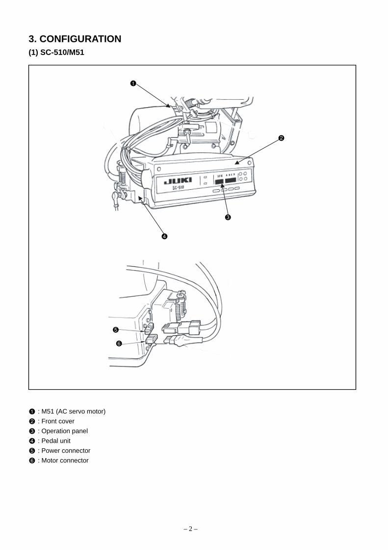
3. CONFIGURATION(1) SC-510/M51
: M51 (AC servo motor)
: Front cover
: Operation panel
: Pedal unit
: Power connector
: Motor connector

– 3 –
NO. DescriptionPower indication LED : Lights up when the power switch is turned ON.
Max. speed limit variable resister : Maximum speed is limited when this resister is moved in the left direction ( ).
Reverse stitching pattern switch : Used for specifying the reverse stitching pattern to be sewn.
Overlapped stitching pattern switch : Used for specifying the overlapped stitching pattern to be sewn.
Constant dimension stitching pattern switch : Used for specifying the constant dimension stitching pattern to be sewn.
Rectangular stitching pattern switch : Used for specifying the rectangular stitching pattern to be sewn.
Automatic reverse stitching at the start of sewing switch : Used for turning ON / OFF the automatic reverse stitching at the start of sewing.
Automatic reverse stitching at the end of sewing switch : Used for turning ON / OFF the automatic reverse stitching at the end of sewing.
Automatic double reverse stitching at the start of sewing switch : Used for turning ON / OFF the automatic double reverse stitching at the start of sewing.
Automatic double reverse stitching at the end of sewing switch : Used for turning ON / OFF the automatic double reverse stitching at the end of sewing.
Switches for setting the number of stitches : Used for setting the number of stitches to be sewn in processes A through D.
Material edge sensor ON / OFF switch : Rendered effective when the material edge sensor is installed on the machine.Used for selecting whether or not the material sensor is used during sewing.
One-shot automatic stitching switch : Start the sewing machine with this switch, and the sewing machine will runautomatically until the material edge is detected or the end of the set number of stitches is reached.
Automatic thread trimming switch :When the material edge is detected, the machine will perform thread trimmingeven when keeping depressing the front part of the pedal.
Thread trimming prohibition switch : Used for prohibiting thread trimming at any occasion.Bobbin thread counter : Indicates the amount of bobbin thread while counting it by subtracting from the set value.When the bobbin thread remaining amount detecting device is installed on the machine, the counter indicates thenumber of times of detecting.
Bobbin counter reset switch : Used for returning the value shown on the bobbin thread counter to the initial value.
Bobbin thread amount setting switch : Used for setting the amount of bobbin thread.
Needle up/down compensating switch : Used when performing needle up / down compensating stitching.
4. EXPLANATION OF OPTIONAL CONTROL PANEL(1) List of control panel of CP-160
1) For the connecting destination of the connector, refer to the item (3) of 7. CONNECTING PROCEDURE WITHJUKI OPTIONAL DEVICES.
2) By connecting of CP-160, all displays of standard operation panel of SC-510 go off.However, error code No. is displayed only at the time of occurrence of error.

– 4 –
(2) Explanation of control panel CP-1601) Reverse stitching pattern
When the sewing machine performs the free stitching operation, themachine performs the reverse stitching operation at the start and end ofsewing.The reverse stitching operation can set the ON and OFF settings.Furthermore, single and double reverse stitching patterns can be selected.Setting of number of stitches or other settings can be performed by oper-ating the control panel.A, B, C and D = 0 to 19 stitches
2) Overlapped stitching pattern
The sewing machine repeats the normal stitching and reverse stitchingby the predetermined time, and performs the line bartacking. Then, themachine makes the thread trimmer actuate and stop to complete the over-lapped stitching procedure.Change of the number of stitches or the number of times of repetition canbe performed by operating the control panel.A, B and C = 0 to 19 stitchesD = 0 to 9 times
3) Constant-dimension stitching pattern
The free stitching process in the reverse stitching pattern becomes theset value of the number of stitches. The sewing machine will automaticallystop (automatically perform thread trimming if the automatic threadtrimming is selected.) after the machine finishes the predetermined numberof stitches in the process of CD.If the automatic thread trimming is not selected, operate the touch-backswitch after the machine has automatically stopped. Then, the machineruns at a low speed (stitch compensation operation). Also, if the pedal isreturned to its neutral position and depressed its front part again, thesewing can be continued regardless of the setting of number of stitches.Setting of number of stitches or selection of automatic thread trimmingcan be performed by operating the control panel.A and B = 0 to 19 stitches CD = 0 to 500 stitches
4) Rectangular stitching pattern
There are 4 operation steps in the process of constant-dimension stitchingpattern. At each operation step the sewing machine automatically stopsafter sewing the predetermined number of stitches. At this time, if thetouch-back switch is operated, the sewing machine runs at a low speed(stitch compensation operation). Also, in case of the last operation step, ifthe pedal is returned to its neutral position and depressed its front partagain, the sewing can be continued regardless of the setting of number ofstitches. However, if the automatic thread trimming is set, the machinewill perform thread trimming. Setting of number of stitches or selection ofautomatic thread trimming can be performed by operating the control panel.A and B = 0 to 19 stitches C and D = 0 to 99 stitches
– 5 –
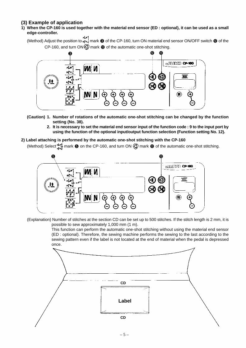
(3) Example of application1) When the CP-160 is used together with the material end sensor (ED : optional), it can be used as a small
edge-controller.
(Method) Adjust the position to mark of the CP-160, turn ON material end sensor ON/OFF switch of the
CP-160, and turn ON mark of the automatic one-shot stitching.
(Caution) 1. Number of rotations of the automatic one-shot stitching can be changed by the functionsetting (No. 38).
2. It is necessary to set the material end sensor input of the function code : 9 to the input port byusing the function of the optional input/output function selection (Function setting No. 12).
Label
CD
CD
2) Label attaching is performed by the automatic one-shot stitching with the CP-160
(Method) Select mark on the CP-160, and turn ON mark of the automatic one-shot stitching.
(Explanation) Number of stitches at the section CD can be set up to 500 stitches. If the stitch length is 2 mm, it ispossible to sew approximately 1,000 mm (1 m).This function can perform the automatic one-shot stitching without using the material end sensor(ED : optional). Therefore, the sewing machine performs the sewing to the last according to thesewing pattern even if the label is not located at the end of material when the pedal is depressedonce.

– 6 –
(4) IP-100E operation panelRefer to the instruction manual of IP-100E/SC-510 for further information.
Re-sewing switch Unused
Needle up/down This is the switch to perform needle up/down compensating stitching.compensating switch (Needle up/down compensating stitching and one stitch compensating
stitching can be changed over with function setting No.22.)
Screen changeover This is the switch to change over the screen.switch
With/without reverse This is the switch to turn ON/OFF automatic reverse feed stitch at sewing start.feed stitch at sewing * This switch cannot be used with the sewing machine which is notstart switch provided with automatic reverse feed stitching device.
With/without reverse This is the switch to turn ON/OFF automatic reverse feed stitch at sewing end.feed stitch at sewing * This switch cannot be used with the sewing machine which is notend switch provided with automatic reverse feed stitching device.
Reset switch This is the switch to make the value of bobbin thread counter or sewingcounter the set value.
Re-sewing switch Information switch Power display lamp
Needle up/down compensating switch Material edge sensor switch Smart media cover
Screen changeover switch One-shot stitching switch Smart media slot
With/without reverse feed stitch With/without automatic thread (Smart media inserting opening)
at sewing start switch trimmer switch Smart media
With/without reverse feed stitch Thread trimming prohibiting switch Optional :
at sewing end switch Counter value setting switch Part No.HX005750000
Reset switch Max. speed limitation variable resistor
Teaching switch
– 7 –
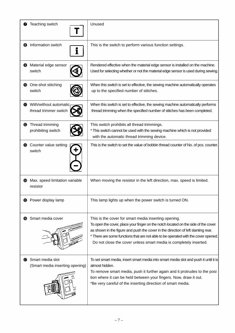
Teaching switch Unused
Information switch This is the switch to perform various function settings.
Material edge sensor Rendered effective when the material edge sensor is installed on the machine.
switch Used for selecting whether or not the material edge sensor is used during sewing.
One-shot stitching When this switch is set to effective, the sewing machine automatically operates
switch up to the specified number of stitches.
With/without automatic When this switch is set to effective, the sewing machine automatically performs
thread trimmer switch thread trimming when the specified number of stitches has been completed.
Thread trimming This switch prohibits all thread trimmings.
prohibiting switch * This switch cannot be used with the sewing machine which is not provided
with the automatic thread trimming device.
Counter value setting This is the switch to set the value of bobbin thread counter of No. of pcs. counter.
switch
Max. speed limitation variable When moving the resistor in the left direction, max. speed is limited.
resistor
Power display lamp This lamp lights up when the power switch is turned ON.
Smart media cover This is the cover for smart media inserting opening.
To open the cover, place your finger on the notch located on the side of the cover
as shown in the figure and push the cover in the direction of left slanting rear.
* There are some functions that are not able to be operated with the cover opened.
Do not close the cover unless smart media is completely inserted.
Smart media slot To set smart media, insert smart media into smart media slot and push it until it is
(Smart media inserting opening) almost hidden.
To remove smart media, push it further again and it protrudes to the posi
tion where it can be held between your fingers. Now, draw it out.
*Be very careful of the inserting direction of smart media.
– 8 –
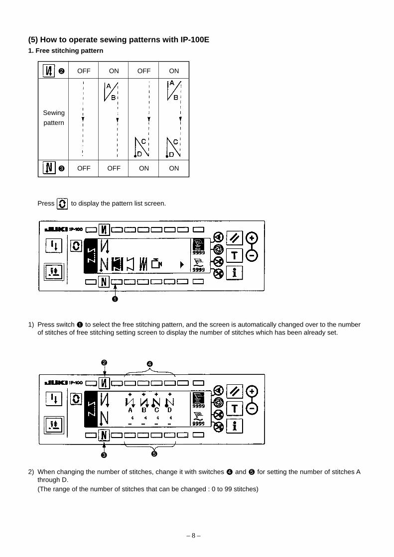
(5) How to operate sewing patterns with IP-100E1. Free stitching pattern
OFF ON OFF ON
Sewing
pattern
OFF OFF ON ON
Press to display the pattern list screen.
1) Press switch to select the free stitching pattern, and the screen is automatically changed over to the numberof stitches of free stitching setting screen to display the number of stitches which has been already set.
2) When changing the number of stitches, change it with switches and for setting the number of stitches Athrough D.(The range of the number of stitches that can be changed : 0 to 99 stitches)

– 9 –
3) Press switch to set the reverse stitching at the start of sewing.
4) Press switch to set the reverse stitching at the end of sewing.
2. Constant dimension stitching pattern
OFF ON OFF ON
Sewing
pattern
OFF OFF ON ONPress to display the pattern list screen.
1) Press switch to select the constant dimension stitching pattern, and the screen is automatically changed over
to the number of stitches of constant dimension stitching setting screen to display the number of stitches which
has been already set.
No setting Reverse stitching Double reverse stitchingat the start of sewing at the start of sewing
No setting Reverse stitching Double reverse stitchingat the end of sewing at the end of sewing

– 10 –
2) When changing the number of stitches of the reverse stitching, change it with switches and for setting thenumber of stitches of A and B.In addition, when changing the number of stitches of the constant dimension stitching, change it with switches and for setting the number of stitches of C D.(The range of the number of stitches that can be changed : A and B = 0 to 19 stitches, C D = 0 to 500 stitches)
3) Press switch to set the reverse stitching at the start of sewing.
4) Press switch to set the reverse stitching at the end of sewing.
5) When automatic thread trimming switch is selected, thread trimming is automatically performed after pro-cesses C D have been completed. (When setting the reverse stitching at the end of sewing, thread trimming isautomatically performed after the reverse stitching at the end of sewing has been completed)When automatic thread trimming switch is not selected, press the touch-back switch after processes C Dhave been completed, and the sewing machine rotates at low speed. (Compensation stitching operation)In addition, when the pedal is returned to the neutral position and the front part of it is depressed again, thesewing can be continued regardless of the setting of the number of stitches.
6) When thread trimming prohibiting switch is selected, the sewing machine will stop with the needle up withoutperforming thread trimming.
7) When one-shot automatic stitching switch is selected, automatic sewing is performed at the set speed without
a break by depressing the front part of the pedal.
3. Overlapped stitching pattern
Press to display the pattern list screen.
1) Press switch to select the overlapped stitching pattern, and the screen is automatically changed over to thenumber of stitches of overlapped stitching setting screen to display the number of stitches which has alreadybeen set.
No setting Reverse stitching Double reverse stitchingat the start of sewing at the start of sewing
No setting Reverse stitching Double reverse stitchingat the end of sewing at the end of sewing

– 11 –
2) When changing the number of stitches, change it with switches and for setting the number of stitches forprocesses A through C. To change the number of times of the whole processes, change it with switches and
for setting the number of processes D.(The range of the number of stitches A,B and C that can be changed : 0 to 19 stitches. The range of the numberof processes D that can be changed : 0 to 9 times)
3) Depress the front part of the pedal once, and the sewing machine will repeat the normal stitching and reversestitching as many as the number of specified times. Then the sewing machine will automatically make the threadtrimmer actuate and will stop to complete the overlapped stitching procedure. (The one-shot automatic stitchingcannot be turned OFF.)
4) When thread trimming prohibiting function is selected, the machine will stop with the needle up upon comple-
tion of the overlapped stitching procedure without performing thread trimming.
4. Square stitching pattern
Press to display the pattern list screen.
1) Press switch to select the square stitching pattern, and the screen is automatically changed over to thenumber of stitches of square stitching setting screen to display the number of stitches which has been already
set.
OFF ON OFF ON
Sewing
pattern
OFF OFF ON ON
– 12 –
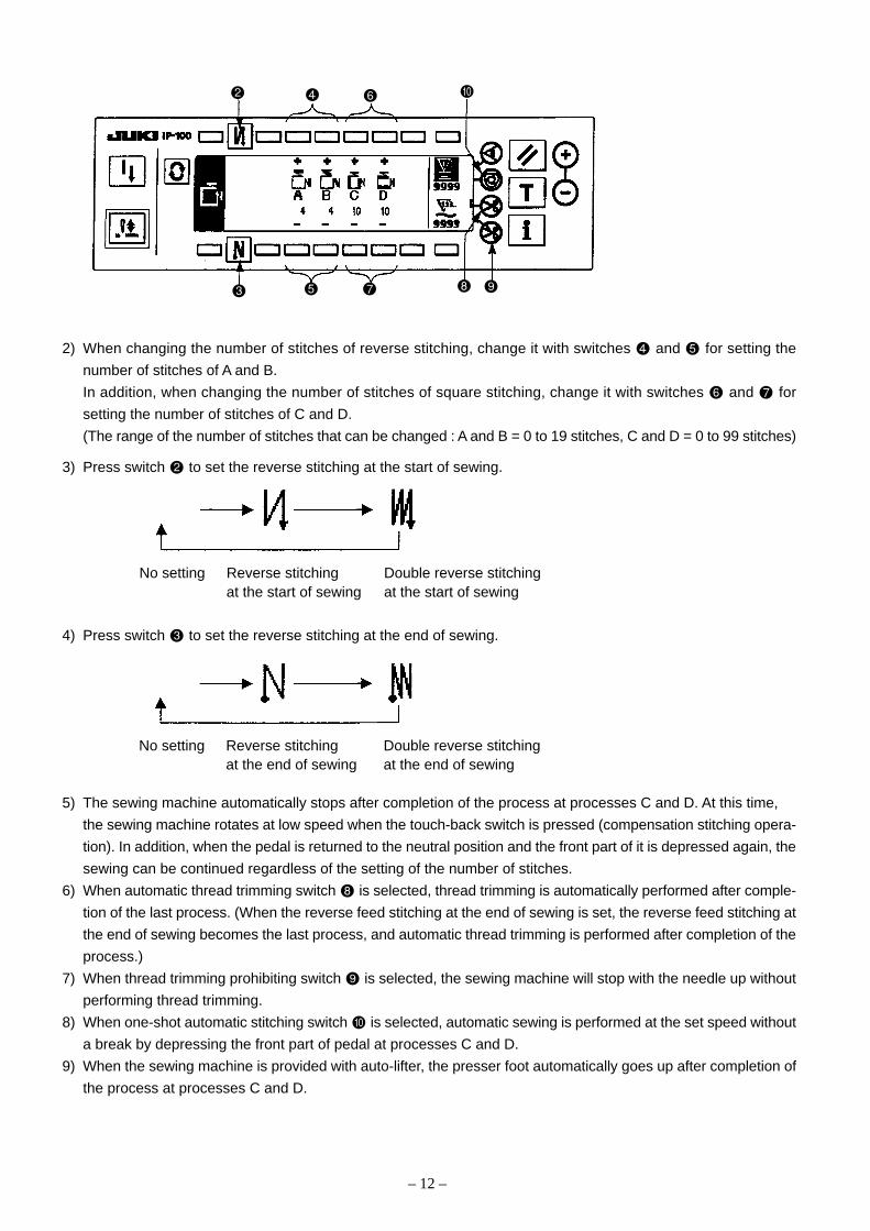
2) When changing the number of stitches of reverse stitching, change it with switches and for setting the
number of stitches of A and B.
In addition, when changing the number of stitches of square stitching, change it with switches and for
setting the number of stitches of C and D.
(The range of the number of stitches that can be changed : A and B = 0 to 19 stitches, C and D = 0 to 99 stitches)
3) Press switch to set the reverse stitching at the start of sewing.
4) Press switch to set the reverse stitching at the end of sewing.
5) The sewing machine automatically stops after completion of the process at processes C and D. At this time,
the sewing machine rotates at low speed when the touch-back switch is pressed (compensation stitching opera-
tion). In addition, when the pedal is returned to the neutral position and the front part of it is depressed again, the
sewing can be continued regardless of the setting of the number of stitches.
6) When automatic thread trimming switch is selected, thread trimming is automatically performed after comple-
tion of the last process. (When the reverse feed stitching at the end of sewing is set, the reverse feed stitching at
the end of sewing becomes the last process, and automatic thread trimming is performed after completion of the
process.)
7) When thread trimming prohibiting switch is selected, the sewing machine will stop with the needle up without
performing thread trimming.
8) When one-shot automatic stitching switch is selected, automatic sewing is performed at the set speed without
a break by depressing the front part of pedal at processes C and D.
9) When the sewing machine is provided with auto-lifter, the presser foot automatically goes up after completion of
the process at processes C and D.
No setting Reverse stitching Double reverse stitchingat the start of sewing at the start of sewing
No setting Reverse stitching Double reverse stitchingat the end of sewing at the end of sewing

– 13 –
In the information mode, you can specify, check, and edit various data and also perform other operations. The
information mode consists of the operator level and maintenance personnel level. Refer to the instruction manual of
IP-100E/SC-510 for the operator level.
[Maintenance personnel level]
1) Turn ON the power.2) Press the switch for 3 seconds to call the information screen.
Information screen (Maintenance personnel level)
1) Press the respective switches to display the screens of the respective functions. (Press the switch , , , or for 3 seconds for corresponding operation.)
Press switch to end the information mode, and the screen returns to that before the information mode.
Version display ..............................1. Refer to the version function.
Sewing common setting ................2. Refer to the sewing common data function.
Function setting .............................Refer to the instruction manual for IP-100E/SC-510.
Sewing management setting .........3. Refer to the sewing management information.
Data communication......................4. Refer to the communication function.
SM format (Smart media) ..............5. Refer to the SM format function.
(Caution) When the smart media format is executed, all data which have been currently recorded willdisappear. Be careful not to use the format for any other than the initialization of the smartmedia.
(6) IP-100E information mode

– 14 –
1) Version function
This function allows you to view the version of each component such as operation panel [IP-100E], IPOP board
[SC-510 expansion], and CTL board [SC-510 main body].
Version display screen
[Standard setting]
(Contents)
1. After checking a version, you can return to the last screen by pressing the switch . If you press the switch
, the information mode ends and the screen before the information mode screen appears again.
R V L
01— 01 — 01 00
Others
Level
Version
Revision
CPU type
: Operation panel program (IP-100E)
: IPOP program (SC-510 expansion [IPOP board])
: Servomotor program (SC-510 main body [CTL board])

– 15 –
2. Sewing common data function
This function allows you to display, specify, and manage various sewing data relating to simplified program,optional input/output, thread trimmer, additional device 1, and additional device 2, and others.
Sewing common data screen (Maintenance personnel level)1. Press the respective switches to display the screens of the respective functions.
Simplified program edit .................. (1) Refer to the simplified program function.Optional input / output setting ........ (2) Refer to the optional input / output function.Thread trimmer device display ....... (3) Tread trimmer device function (Refer to the instruction manual
for IP-100E/SC-510.)Additional device 1 setting ............. (4) Additional device function (Refer to the instruction manual for
IP-100E/SC-510.)Additional device 2 setting ............. (4) Additional device function (Refer to the instruction manual for
IP-100E/SC-510.)
2.Press switch to return to the information screen (maintenance personnel level), and press switch to end theinformation mode. Then the screen returns to that before the information mode.
(1) Simplified program functionThis is the function to create the simplified program which takes in the various internal signals and the signal fromthe outside (connector), and can control the output of special signals to the outside (connector) and the compli-cated motion of the sewing machine with SC-510 main unit only without using the exclusive input device or thelike.
Simplified program edit the 1st screen[Program command “END” : standard setting]1) Press switches and to select programs (No.1 to 4).2) Press switches and to select steps (No.1 to 20).When the program command selected with switches
and is “END”, the step No. becomes the last step and it is not possible to proceed to the next step No.3) Press switches and to select program commands (function code No. 0 to 20).
– 16 –
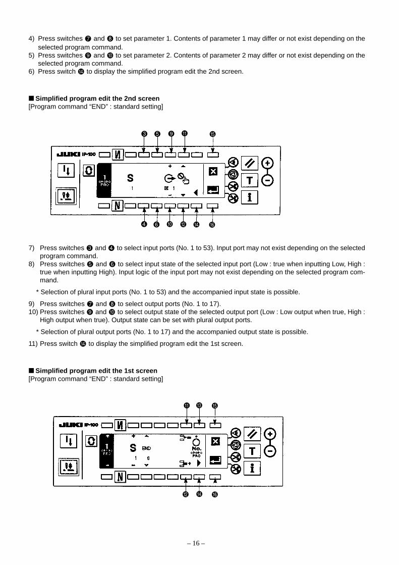
4) Press switches and to set parameter 1. Contents of parameter 1 may differ or not exist depending on theselected program command.
5) Press switches and to set parameter 2. Contents of parameter 2 may differ or not exist depending on theselected program command.
6) Press switch to display the simplified program edit the 2nd screen.
Simplified program edit the 2nd screen[Program command “END” : standard setting]
7) Press switches and to select input ports (No. 1 to 53). Input port may not exist depending on the selectedprogram command.
8) Press switches and to select input state of the selected input port (Low : true when inputting Low, High :true when inputting High). Input logic of the input port may not exist depending on the selected program com-mand.
* Selection of plural input ports (No. 1 to 53) and the accompanied input state is possible.
9) Press switches and to select output ports (No. 1 to 17).10) Press switches and to select output state of the selected output port (Low : Low output when true, High :
High output when true). Output state can be set with plural output ports.
* Selection of plural output ports (No. 1 to 17) and the accompanied output state is possible.
11) Press switch to display the simplified program edit the 1st screen.
Simplified program edit the 1st screen[Program command “END” : standard setting]

– 17 –
12) Repeat the procedure from 2) through 11) for editing the next step. After completion of editing, press the switch to enable the program. (The illustration on the previous page shows the state of program off. The display
changes to the illustration below and the program becomes enabled when the switch is pressed.)
13) When switch is pressed to store this program in memory and end the editing, display the screen of theillustration below. When switch is pressed, all contents of the edit up to that time are invalidated and the statereturns to that before edit.
14) Lastly, turn OFF the power switch. This simplified program works when the power switch is turned ON again.
• Inserting procedure of the stepWhen switch is pressed, a step (program command “DELY” is set) is newly inserted after the displayed step,and the display is changed over to that of the step.
• Deleting procedure of the stopWhen switch is pressed, the displayed step is deleted, the next step is advanced, and the display is changedover to that of the step.
• Effective simplified program No. display at the time of sewingSimplified program No. which has been set effective is displayed in the frame of dotted line of the illustrationbelow in the normal sewing screen or the like, and which simplified program No. is working can be confirmed.The illustration below shows the display when all of No. 1 to 4 are set effective. Simplified program No. whichhas been set invalidate is not displayed
Program on Program off

– 18 –
MEMO

—
—
: No setting
: H input
: L input
: No setting
: H input
: L input
: No setting
: H input
: L input
: No setting
: H input
: L input
—
—
– 19 –
[Program command list]
Parameter 1 Parameter 2 Input port Output port
Display Setting range Display Setting range Display Setting range Display Setting range
Command displayFunction code No.
Commandname
Description of command
0
1
2
3
4
5
6
7
Completion
Delay
ANDconditionalbranch
ORconditionalbranch
Number ofstitches ANDconditionalbranch
Number ofstitches ORconditionalbranch
Jump repeatcounter
Rotationspeedcommand
—
—
1 to 20
1 to 20
1 to 20
1 to 20
1 to 20
0 to 999
—
—
(Skip destinationstep No.)1 to 20 : Step No.
(Skip destinationstep No.) 1 to 20 : Step No.
(Skip destinationstep No.) 1 to 20 : Step No.
(Skip destinationstep No.) 1 to 20 : Step No.
(Jump) 1 to 20 : Step No.
(Speed) 0 to 999 : X10
—
0 to 999
0 to 999
0 to 999
0 to 999
0 to 999
0 to 999
0 to 999
—
(Delay time)0 : Command invalid1 to 999 : msec
(Delay time)0 : Waiting input un-
til completion ofcondition
1 to 999 : msec
(Delay time)0 : Waiting input un-
til completion ofcondition
1 to 999 : msec
(Number of stitches)0 : Command invalid1 to 999 : msec
(Number of stitches)0 : Command invalid1 to 999 : msec
(Repeat count value)0 : Infinite1 to 999 :Time
(Delay time)0 : Delay time invalid1 to 999 : msec
—
—
1 to 53
1 to 53
1 to 53
1 to 53
—
—
1 to 17
1 to 17
1 to 17
1 to 17
1 to 17
1 to 17
1 to 17
1 to 17
: No setting
: H output
: L output
: No setting
: H output
: L output
: No setting
: H output
: L output
: No setting
: H output
: L output
: No setting
: H output
: L output
: No setting
: H output
: L output
: No setting
: H output
: L output
: No setting
: H output
: L output
End of program (initial setting)
To next step after lapse of delay time
Moves to next step when all conditions specified in the input setting are completed(AND input). Jumps to the step set at skip destination step No. when input conditionsare not completed and delay time has lapsed.
Moves to next step when any of conditions specified at input setting is completed (ORinput). Jumps to the step set at skip destination step No. when input conditions are notcompleted and delay time has lapsed.
Jumps to the step specified at skip destination step No. when all input setting condi-tions are completed within the set value of number of stitches setting (AND input), andmoves to next step after number of stitches has finished.
Jumps to the step specified at skip destination step No. when any of input settingconditions is completed within the set value of number of stitches setting (OR input),and moves to next step after number of stitches has finished.
Repeats between the specified steps at jump until repeat count value is over. Loopsinfinitely at set value 0.(Caution) Do not perform the nest input of this command.
Speed of the swing machine can be set. The machine runs at the set speed within theset delay time, and the speed command is released after lapse of delay time. Mini-mum number of revolutions does not become less than the set value of function set-ting No.35 Minimum number of revolutions of pedal. Also, maximum number of revo-lutions does not become more then the set value.
*State setting of input ports (No.1 to 53) and output ports (No.1 to 17) can be individually performed. Refer to 9.-(5) Simplified program information input setting code list and connector location list for the input/output port numbers.
Parameter 1 Parameter 2 Input port Output port
Display Setting range Display Setting range Display Setting range Display Setting range
– 20 –
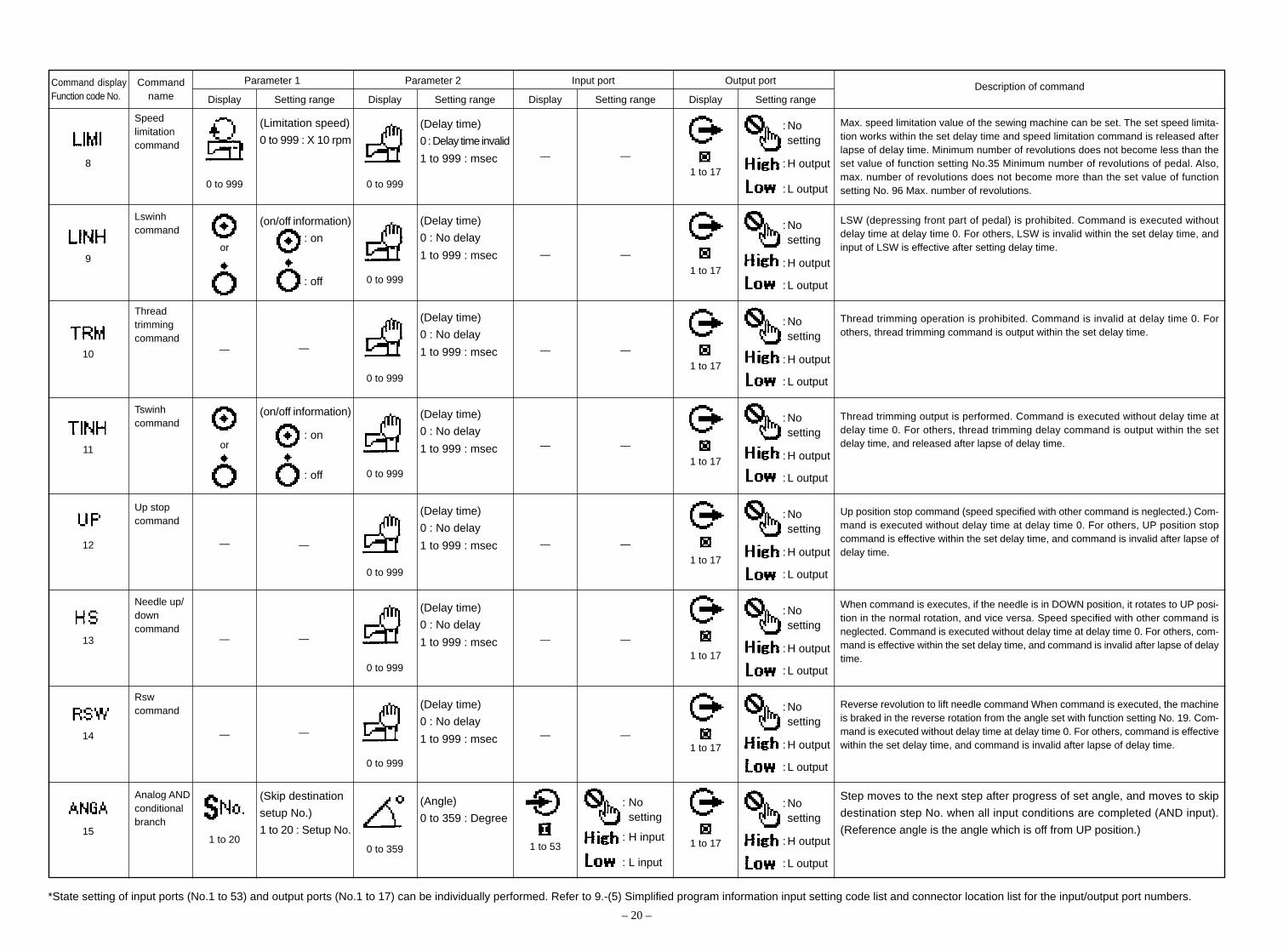
8
9
10
11
12
13
14
15
Speedlimitationcommand
Lswinhcommand
Threadtrimmingcommand
Tswinhcommand
Up stopcommand
Needle up/downcommand
Rswcommand
Analog ANDconditionalbranch
0 to 999
or
—
or
—
—
—
1 to 20
(Limitation speed)
0 to 999 : X 10 rpm
(on/off information)
: on
: off
—
(on/off information)
: on
: off
—
—
—
(Skip destination
setup No.)
1 to 20 : Setup No.
0 to 999
0 to 999
0 to 999
0 to 999
0 to 999
0 to 999
0 to 999
0 to 359
(Delay time)
0 : Delay time invalid
1 to 999 : msec
(Delay time)
0 : No delay
1 to 999 : msec
(Delay time)
0 : No delay
1 to 999 : msec
(Delay time)
0 : No delay
1 to 999 : msec
(Delay time)
0 : No delay
1 to 999 : msec
(Delay time)
0 : No delay
1 to 999 : msec
(Delay time)
0 : No delay
1 to 999 : msec
(Angle)
0 to 359 : Degree
—
—
—
—
—
—
—
1 to 53
—
—
—
—
—
—
—
: Nosetting
: H input
: L input
1 to 17
1 to 17
1 to 17
1 to 17
1 to 17
1 to 17
1 to 17
1 to 17
: Nosetting
: H output
: L output
: Nosetting
: H output
: L output
: Nosetting
: H output
: L output
: Nosetting
: H output
: L output
: Nosetting
: H output
: L output
: Nosetting
: H output
: L output
: Nosetting
: H output
: L output
: Nosetting
: H output
: L output
Max. speed limitation value of the sewing machine can be set. The set speed limita-tion works within the set delay time and speed limitation command is released afterlapse of delay time. Minimum number of revolutions does not become less than theset value of function setting No.35 Minimum number of revolutions of pedal. Also,max. number of revolutions does not become more than the set value of functionsetting No. 96 Max. number of revolutions.
LSW (depressing front part of pedal) is prohibited. Command is executed withoutdelay time at delay time 0. For others, LSW is invalid within the set delay time, andinput of LSW is effective after setting delay time.
Thread trimming operation is prohibited. Command is invalid at delay time 0. Forothers, thread trimming command is output within the set delay time.
Thread trimming output is performed. Command is executed without delay time atdelay time 0. For others, thread trimming delay command is output within the setdelay time, and released after lapse of delay time.
Up position stop command (speed specified with other command is neglected.) Com-mand is executed without delay time at delay time 0. For others, UP position stopcommand is effective within the set delay time, and command is invalid after lapse ofdelay time.
When command is executes, if the needle is in DOWN position, it rotates to UP posi-tion in the normal rotation, and vice versa. Speed specified with other command isneglected. Command is executed without delay time at delay time 0. For others, com-mand is effective within the set delay time, and command is invalid after lapse of delaytime.
Reverse revolution to lift needle command When command is executed, the machineis braked in the reverse rotation from the angle set with function setting No. 19. Com-mand is executed without delay time at delay time 0. For others, command is effectivewithin the set delay time, and command is invalid after lapse of delay time.
Step moves to the next step after progress of set angle, and moves to skip
destination step No. when all input conditions are completed (AND input).
(Reference angle is the angle which is off from UP position.)
*State setting of input ports (No.1 to 53) and output ports (No.1 to 17) can be individually performed. Refer to 9.-(5) Simplified program information input setting code list and connector location list for the input/output port numbers.
Description of commandCommand displayFunction code No.
Commandname
– 21 –
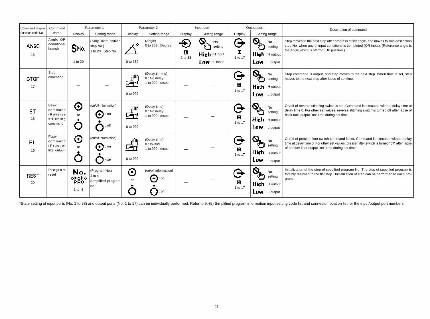
16
17
18
19
20
Angle ORconditionalbranch
Stopcommand
BTswcommand( R e v e r s es t i t c h i n gcommand
FLswcommand( P r e s s e rlifter output)
P r o g r a mreset
1 to 20
—
or
or
1 to 4
(Skip destination
step No.)
1 to 20 : Step No.
—
(on/off information)
: on
: off
(on/off information)
: on
: off
(Program No.)
1 to 4 :
Simplified program
No.
0 to 359
0 to 999
0 to 999
0 to 999
or
(Angle)0 to 359 : Degree
(Delay ti mme)0 : No delay1 to 999 : msec
(Delay time)0 : No delay1 to 999 : msec
(Delay time)0 : Invalid1 to 999 : msec
(on/off information)
: on
: off
1 to 53
—
—
—
—
: Nosetting
: H input
: L input
—
—
—
—
1 to 17
1 to 17
1 to 17
1 to 17
1 to 17
: Nosetting
: H output
: L output
: Nosetting
: H output
: L output
: Nosetting
: H output
: L output
: Nosetting
: H output
: L output
: Nosetting
: H output
: L output
Step moves to the next step after progress of set angle, and moves to skip destinationstep No. when any of input conditions is completed (OR input). (Reference angle isthe angle which is off from UP position.)
Stop command is output, and step moves to the next step. When time is set, stepmoves to the next step after lapse of set time.
On/off of reverse stitching switch is set. Command is executed without delay time atdelay time 0. For other set values, reverse stitching switch is turned off after lapse ofback-tuck output “on” time during set time.
On/off of presser lifter switch command is set. Command is executed without delaytime at delay time 0. For other set values, presser lifter switch is turned “off” after lapseof presser lifter output “on” time during set time.
Initialization of the step of specified program No. The step of specified program isforcibly returned to the fist step. Initialization of step can be performed to each pro-gram.
*State setting of input ports (No. 1 to 53) and output ports (No. 1 to 17) can be individually performed. Refer to 9.-(5) Simplified program information input setting code list and connector location list for the input/output port numbers.
Parameter 1 Parameter 2 Input port Output port
Display Setting range Display Setting range Display Setting range Display Setting rangeDescription of commandCommand display
Function code No.Command
name

MEMO
– 22 –
– 23 –
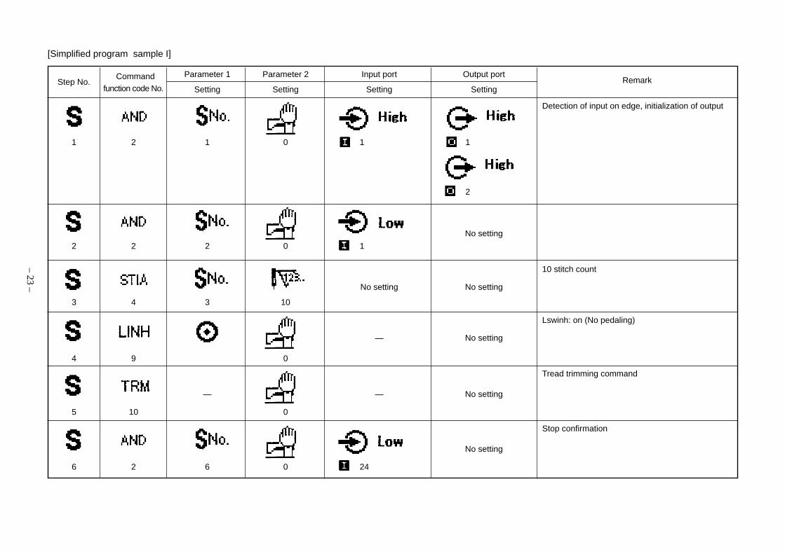
Detection of input on edge, initialization of output
1 2 1 0 1 1
2
No setting
2 2 2 0 1
10 stitch count
No setting No setting
3 4 3 10
Lswinh: on (No pedaling)
— No setting
4 9 0
Tread trimming command
— 0 — No setting
5 10 0
Stop confirmation
No setting
6 2 6 0 24
Parameter 1 Parameter 2 Input port Output port
Setting Setting Setting Setting
Commandfunction code No.
Step No. Remark
[Simplified program sample I]

– 24 –
Delay: 50 ms, output 1: on
— —
7 1 50 1
Delay: 50 ms, output 2: on
— —
8 1 50 2
Delay: 100 ms, output 1: off
— —
9 1 100 1
Cancellation of thread trimming command, output 2: off
— —
10 17 0 2
Lswinh: off (Cancellation of no pedaling)
— No setting
11 9 0
Repeat
— No setting
12 6 1 0
— — — No setting
13 0
Parameter 1 Parameter 2 Input port Output port
Setting Setting Setting Setting
Commandfunction code No.
Step No. Remark
– 25 –
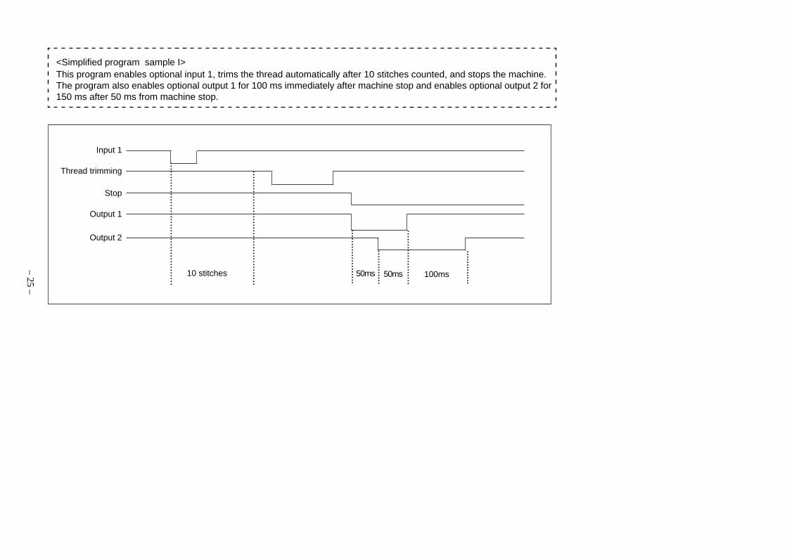
<Simplified program sample I>This program enables optional input 1, trims the thread automatically after 10 stitches counted, and stops the machine.The program also enables optional output 1 for 100 ms immediately after machine stop and enables optional output 2 for150 ms after 50 ms from machine stop.
Input 1
Thread trimming
Stop
Output 1
Output 2
10 stitches 50ms 50ms 100ms
............................................
.........................................
....................
....................
.............
.............

– 26 –
Detection of input on edge, output 2: on
1 2 1 0 1 1
2
on delay: 20 ms (chatter protection)
No setting
2 2 4 20 1
on waiting
— No setting
3 6 2 0
Speed limit at 2000 rpm (in steps of 10 rpm)
— No setting
4 8 200 0
Detection of input on edge, output 1: on
5 2 5 0 1 1
2
Parameter 1 Parameter 2 Input port Output port
Setting Setting Setting Setting
Commandfunction code No.
Step No. Remark
[Simplified program sample II]
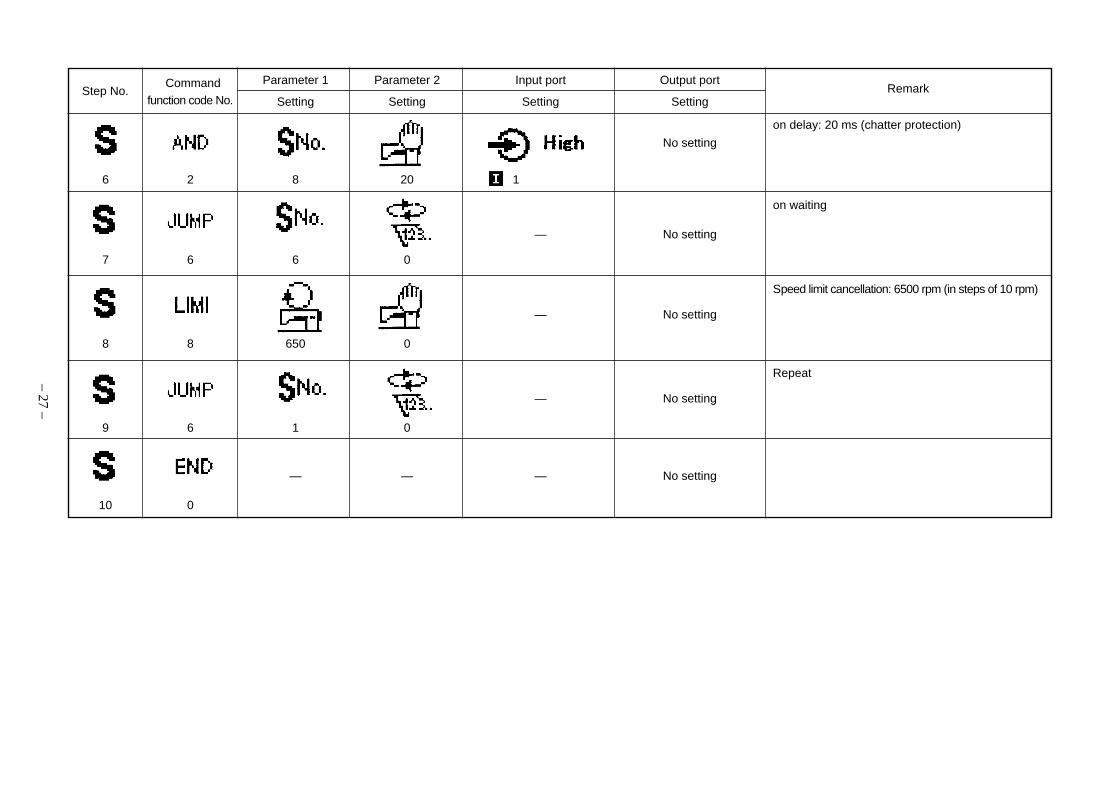
– 27 –
on delay: 20 ms (chatter protection)
No setting
6 2 8 20 1
on waiting
— No setting
7 6 6 0
Speed limit cancellation: 6500 rpm (in steps of 10 rpm)
— No setting
8 8 650 0
Repeat
— No setting
9 6 1 0
— — — No setting
10 0
Parameter 1 Parameter 2 Input port Output port
Setting Setting Setting Setting
Commandfunction code No.
Step No. Remark
– 28 –
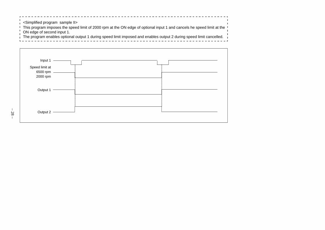
.........................................
Input 1
Speed limit at6500 rpm2000 rpm
Output 1
Output 2
......................................
<Simplified program sample II>This program imposes the speed limit of 2000 rpm at the ON edge of optional input 1 and cancels he speed limit at theON edge of second input 1.The program enables optional output 1 during speed limit imposed and enables output 2 during speed limit cancelled.
– 29 –
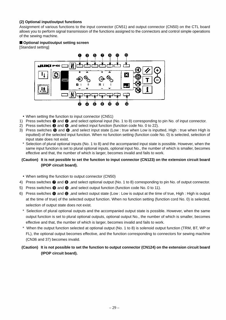
(2) Optional input/output functionsAssignment of various functions to the input connector (CN51) and output connector (CN50) on the CTL boardallows you to perform signal transmission of the functions assigned to the connectors and control simple operationsof the sewing machine.
Optional input/output setting screen[Standard setting]
• When setting the function to input connector (CN51)1) Press switches and ,and select optional input (No. 1 to 8) corresponding to pin No. of input connector.2) Press switches and ,and select input function (function code No. 0 to 22).3) Press switches and ,and select input state (Low : true when Low is inputted, High : true when High is
inputted) of the selected input function. When no function setting (function code No. 0) is selected, selection ofinput state does not exist.
* Selection of plural optional inputs (No. 1 to 8) and the accompanied input state is possible. However, when thesame input function is set to plural optional inputs, optional input No., the number of which is smaller, becomeseffective and that, the number of which is larger, becomes invalid and fails to work.
(Caution) It is not possible to set the function to input connector (CN123) on the extension circuit board(IPOP circuit board).
• When setting the function to output connector (CN50)
4) Press switches and ,and select optional output (No. 1 to 8) corresponding to pin No. of output connector.
5) Press switches and ,and select output function (function code No. 0 to 11).
6) Press switches and ,and select output state (Low : Low is output at the time of true, High : High is output
at the time of true) of the selected output function. When no function setting (function cord No. 0) is selected,
selection of output state does not exist.
* Selection of plural optional outputs and the accompanied output state is possible. However, when the same
output function is set to plural optional outputs, optional output No., the number of which is smaller, becomes
effective and that, the number of which is larger, becomes invalid and fails to work.
* When the output function selected at optional output (No. 1 to 8) is solenoid output function (TRM, BT, WP or
FL), the optional output becomes effective, and the function corresponding to connectors for sewing machine
(CN36 and 37) becomes invalid.
(Caution) It is not possible to set the function to output connector (CN124) on the extension circuit board
(IPOP circuit board).
– 30 –
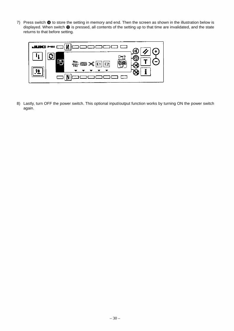
7) Press switch to store the setting in memory and end. Then the screen as shown in the illustration below isdisplayed. When switch is pressed, all contents of the setting up to that time are invalidated, and the statereturns to that before setting.
8) Lastly, turn OFF the power switch. This optional input/output function works by turning ON the power switchagain.

– 31 –
[Input function list]The following chart shows available input functions. Use this chart after referring to “Setting procedure of optionalpower and setting procedure of jumper for input changeover”.
(Caution) For assigning the input function to the input connector, CN51, use +5 V or less voltage for thefunction signal transmitting to the optional input terminal. Failure to observe this may causedamage to the board.
Function name Input state setting Description of function
No function setting (Standard setting state)
—
0
Needle up/down Every time switch is pressed, as many as halfcompensating stitching stitch is fed in normal direction. (Same motion
as that of needle up/down compensating stitc-: L input : H input hing switch of the operation panel.)
1
Back compensating Reverse stitching at low speed is performedstitching while switch is held pressed. (Effective only
: L input : H input when constant-dimension stitching is selected2 with the operation panel.)
Function of cancel of once Depressing the back part of the pedal
of reverse stitching at end after pressing the switch cancels reverse: L input : H input feed stitching once.
3
Thread trimming function The function works as thread trimmingswitch.
: L input : H input4
Presser lifter function The function works as presser lifter switch.
: L input : H input5
One stitch compensating Every time switch is pressed, one stitchstitching sewing motion is executed.
: L input : H input6
Function of cancel of Invalid/effective can be alternately changedreverse stitching at start over by operating optional switch.
: L input : H input7
Function of lifting presser Every time switch is pressed, function oflifter when pedal is in automatically lifting/not lifting presserneutral position : L input : H input lifter when pedal is in neutral position can
8 be selected.
Material end sensor input This function works as input signal ofmaterial end sensor.
: L input : H input9
Function of prohibition of This function prohibits rotation by meanspressing front part of pedal of pedal.
: L input : H input10
Function displayFunction code No.

– 32 –
Function name Input state setting Description of function
Function of prohibition of This function prohibits thread trimmingthread trimming output output.
: L input : H input11
Low speed command input This function works as low speed switchfor standing machine.
: L input : H input12
High speed command input This function works as high speed switchfor standing machine.
: L input : H input13
Needle lift function When switch is pressed during DOWN stop,UP stop motion is performed.
: L input : H input14
Function of reverse revolution When switch is pressed during DOWN stop,to lift needle reverse revolution is performed and the
: L input : H input machine is braked at the specified angle.15
Safety switch input This function prohibits rotation.
: L input : H input16
Thread trimmer knife This function works as input signal of threadsensor input trimmer knife sensor.
: L input : H input17
Cancel/addition of automatic Every time switch is pressed, this functionreverse stitching switch input performs cancel or addition of reverse
: L input : H input stitching at start or end.18
Alternate vertical movement Every time switch is pressed, this functionamount change panel switch performs alternate vertical movementinput : L input : H input amount change output.
19
Alternate vertical movement While switch is held pressed, this functionamount change knee switch performs alternate vertical movementinput : L input : H input amount change output.
20
2-pitch alternate input Every time switch is pressed, this functioninverses 2-pitch change output.
: L input : H input21
2-pitch momentary switch While switch is held pressed, this functionperforms 2-pitch change output.
: L input : H input22
Function displayFunction code No.
– 33 –
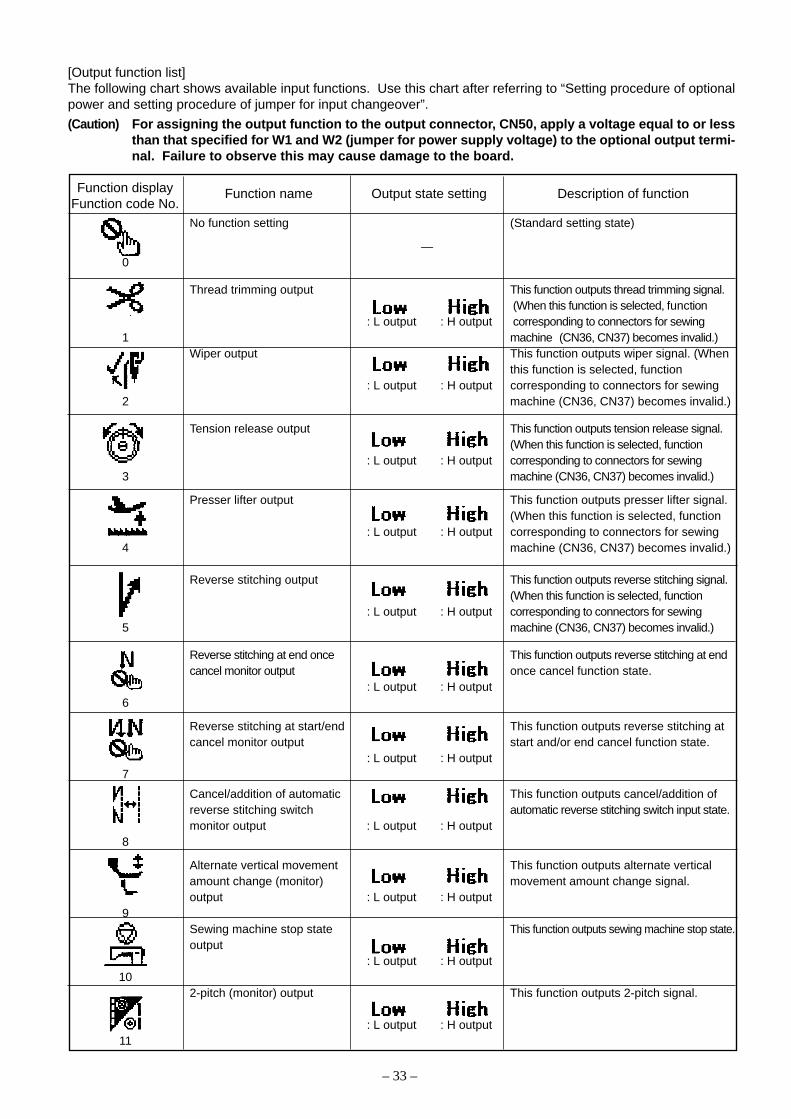
No function setting (Standard setting state)
—0
Thread trimming output This function outputs thread trimming signal. (When this function is selected, function
: L output : H output corresponding to connectors for sewing1 machine (CN36, CN37) becomes invalid.)
Wiper output This function outputs wiper signal. (Whenthis function is selected, function
: L output : H output corresponding to connectors for sewing2 machine (CN36, CN37) becomes invalid.)
Tension release output This function outputs tension release signal.(When this function is selected, function
: L output : H output corresponding to connectors for sewing3 machine (CN36, CN37) becomes invalid.)
Presser lifter output This function outputs presser lifter signal.(When this function is selected, function
: L output : H output corresponding to connectors for sewing4 machine (CN36, CN37) becomes invalid.)
Reverse stitching output This function outputs reverse stitching signal.(When this function is selected, function
: L output : H output corresponding to connectors for sewing5 machine (CN36, CN37) becomes invalid.)
Reverse stitching at end once This function outputs reverse stitching at endcancel monitor output once cancel function state.
: L output : H output6
Reverse stitching at start/end This function outputs reverse stitching atcancel monitor output start and/or end cancel function state.
: L output : H output7
Cancel/addition of automatic This function outputs cancel/addition ofreverse stitching switch automatic reverse stitching switch input state.monitor output : L output : H output
8
Alternate vertical movement This function outputs alternate verticalamount change (monitor) movement amount change signal.output : L output : H output
9Sewing machine stop state This function outputs sewing machine stop state.output
: L output : H output10
2-pitch (monitor) output This function outputs 2-pitch signal.
: L output : H output11
[Output function list]The following chart shows available input functions. Use this chart after referring to “Setting procedure of optionalpower and setting procedure of jumper for input changeover”.
(Caution) For assigning the output function to the output connector, CN50, apply a voltage equal to or lessthan that specified for W1 and W2 (jumper for power supply voltage) to the optional output termi-nal. Failure to observe this may cause damage to the board.
Function name Output state setting Description of functionFunction displayFunction code No.
– 34 –
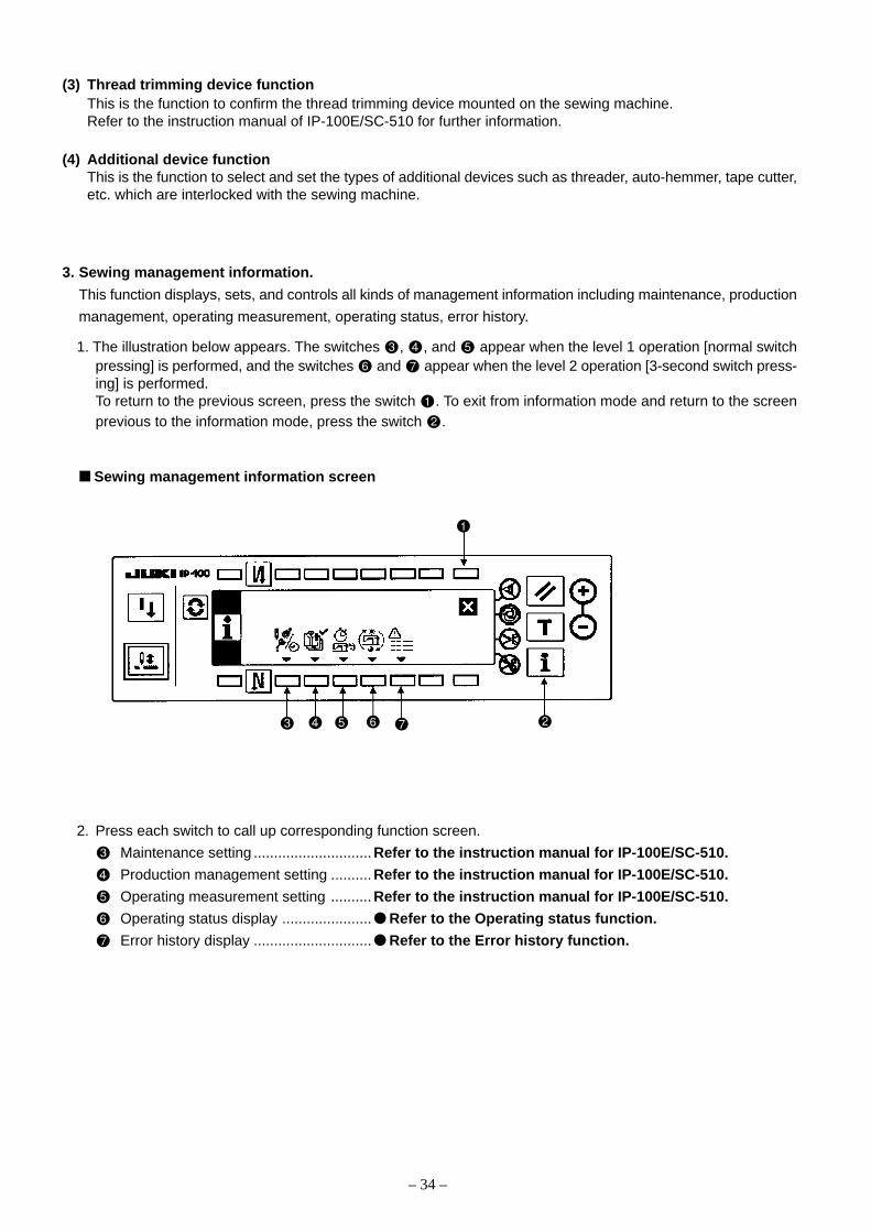
3. Sewing management information.
This function displays, sets, and controls all kinds of management information including maintenance, production
management, operating measurement, operating status, error history.
1. The illustration below appears. The switches , , and appear when the level 1 operation [normal switchpressing] is performed, and the switches and appear when the level 2 operation [3-second switch press-ing] is performed.To return to the previous screen, press the switch . To exit from information mode and return to the screenprevious to the information mode, press the switch .
Sewing management information screen
2. Press each switch to call up corresponding function screen.
Maintenance setting ............................. Refer to the instruction manual for IP-100E/SC-510.
Production management setting .......... Refer to the instruction manual for IP-100E/SC-510.
Operating measurement setting .......... Refer to the instruction manual for IP-100E/SC-510.
Operating status display ...................... Refer to the Operating status function.
Error history display ............................. Refer to the Error history function.
(3) Thread trimming device functionThis is the function to confirm the thread trimming device mounted on the sewing machine.Refer to the instruction manual of IP-100E/SC-510 for further information.
(4) Additional device functionThis is the function to select and set the types of additional devices such as threader, auto-hemmer, tape cutter,etc. which are interlocked with the sewing machine.

– 35 –
Operating status function
This function displays the operating status of the sewing machine including each operating time, energization
time, thread trim count, and total stitches.
Operating status screen
(Contents)
: Operation time (Unit : h)
: Energization time (Unit : h)
: Thread trim count (Unit : Number of counts)
: Stitche count (Unit : in 1,000 stitches)
1. Press the switch to return to the previous screen after viewing the operating status of the sewing machine.
To exit from the information mode and return to the screen previous to the information mode, press the switch
.

– 36 –
Error history function
This function display error occurrence information (error No., error duration, etc.) of the sewing machine.
Error historu screen
(Contents)
1. Press the switch to return to the previous screen after viewing the occurrence information (latest error
highlighted and top listed) of the sewing machine. If two or more errors occur at the same time, press the
switch or to scroll the list up or down respectively. Up to approximately 100 errors (depending on
memory capacity) can be saved in the error history in reverse chronological order.
To exit from the information mode and return to the screen previous to the information mode, press the switch
.
History No. Error No. Error duration (Unit : h) [Energization time]
– 37 –
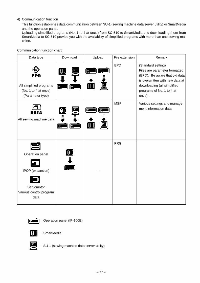
4) Communication function
This function establishes data communication between SU-1 (sewing machine data server utility) or SmartMediaand the operation panel.Uploading simplified programs (No. 1 to 4 at once) from SC-510 to SmartMedia and downloading them fromSmartMedia to SC-510 provide you with the availability of simplified programs with more than one sewing ma-chine.
Communication function chart
Data type Download Upload File extension Remark
EPD (Standard setting)
Files are parameter formatted
(EPD). Be aware that old data
is overwritten with new data at
All simplified programs downloading (all simplified
(No. 1 to 4 at once) programs of No. 1 to 4 at
(Parameter type) once).
MSP Various settings and manage-
ment information data
All sewing machine data
PRG
Operation panel
IPOP (expansion) —
Servomotor
Various control program
data
: Operation panel (IP-100E)
: SmartMedia
: SU-1 (sewing machine data server utility)

– 38 –
Communication configuration screen
[Standard setting]
1. Press the switch to call up the data selection screen.
Data selection screen
[Standard setting]
2. The illustration above indicates that parameter formatted data (EPD) is selected. (highlighted)
Press the switch corresponding to your selected data type.
Parameter formatted data (EPD) ........................ All simplified program data (No. 1 to 4)
All sewing machine data (MSP) .......................... Various settings and management information data
Operation panel program (PRG) ......................... Operation panel control software (IP-100E)
IPOP program (PRG) .......................................... IPOP control software (SC-510 expansion [IPOP board])
Servomotor program (PRG) ................................ Sewing machine control software (SC-510 main body[CTL board])
– 39 –
3. Press the switch to save the selected contents and call up the previous screen. To delete the selected
contents and call up the previous screen, press the switch .
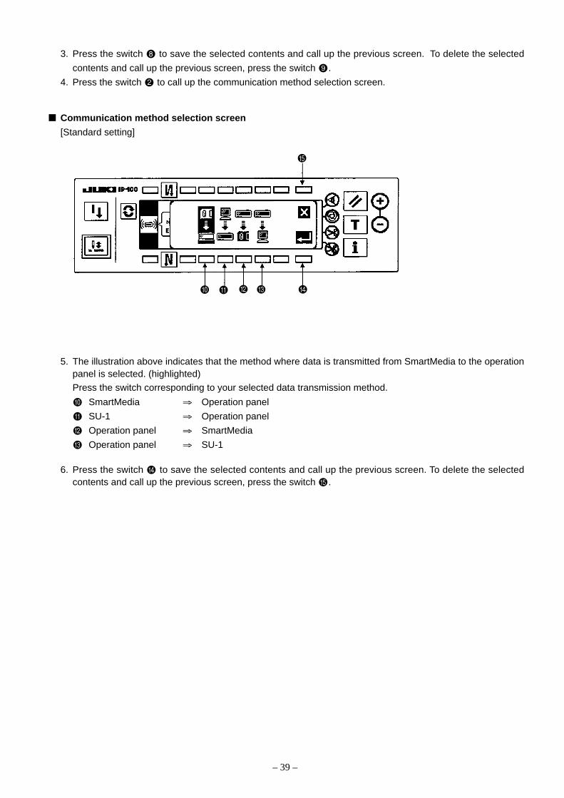
4. Press the switch to call up the communication method selection screen.
Communication method selection screen
[Standard setting]
5. The illustration above indicates that the method where data is transmitted from SmartMedia to the operationpanel is selected. (highlighted)
Press the switch corresponding to your selected data transmission method.
SmartMedia ⇒ Operation panel
SU-1 ⇒ Operation panel
Operation panel ⇒ SmartMedia
Operation panel ⇒ SU-1
6. Press the switch to save the selected contents and call up the previous screen. To delete the selectedcontents and call up the previous screen, press the switch .

– 40 –
Communication configuration screen
7. Press the switch or to select or specify the data number. The displayed contents and operations vary
depending on data type and communication method.
8. Press the switch after completion of all settings to start communication. During communication, an hour-glass appears for parameter formatted data and all sewing machine data, and a percentage (%) bar graphappears for program data.
9. To upload parameter formatted data after communication, return to the communication configuration screen.
When the display indicates you to turn off the power, do as indicated.
(Caution) Never turn off the power during communication. If you turn off the power during communica-tion for any reason, follow the procedure again.
10%0% 100%
Percentage (%) bar graph
Hourglass
Power OFF indication
The displayed contents vary dependingon settings.

– 41 –
[1] Upload of simplified program data
Uploading simplified programs (No. 1 to 4 at once) from SC-510 to SmartMedia provides you with the availability
of simplified programs with more than one sewing machine.
The following explains how to copy simplified programs (No. 1 to 4 at once) as data file No. 5 (parameter
formatted data (EPD)) into a SmartMedia card.
1) Select “parameter formatted data (EPD)” on the data selection screen and select “operation panel” ⇒
“SmartMedia” on the communication method selection screen to call up the screen below.
Communication configuration screen
2) Press the switch to call up the data file No. entry screen.
Data file No. entry screen
– 42 –
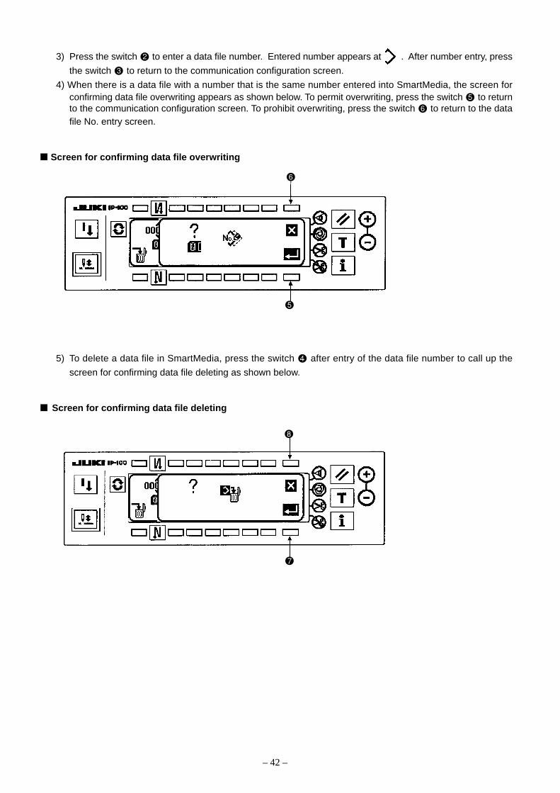
3) Press the switch to enter a data file number. Entered number appears at . After number entry, press
the switch to return to the communication configuration screen.
4) When there is a data file with a number that is the same number entered into SmartMedia, the screen forconfirming data file overwriting appears as shown below. To permit overwriting, press the switch to returnto the communication configuration screen. To prohibit overwriting, press the switch to return to the datafile No. entry screen.
Screen for confirming data file overwriting
5) To delete a data file in SmartMedia, press the switch after entry of the data file number to call up the
screen for confirming data file deleting as shown below.
Screen for confirming data file deleting
– 43 –
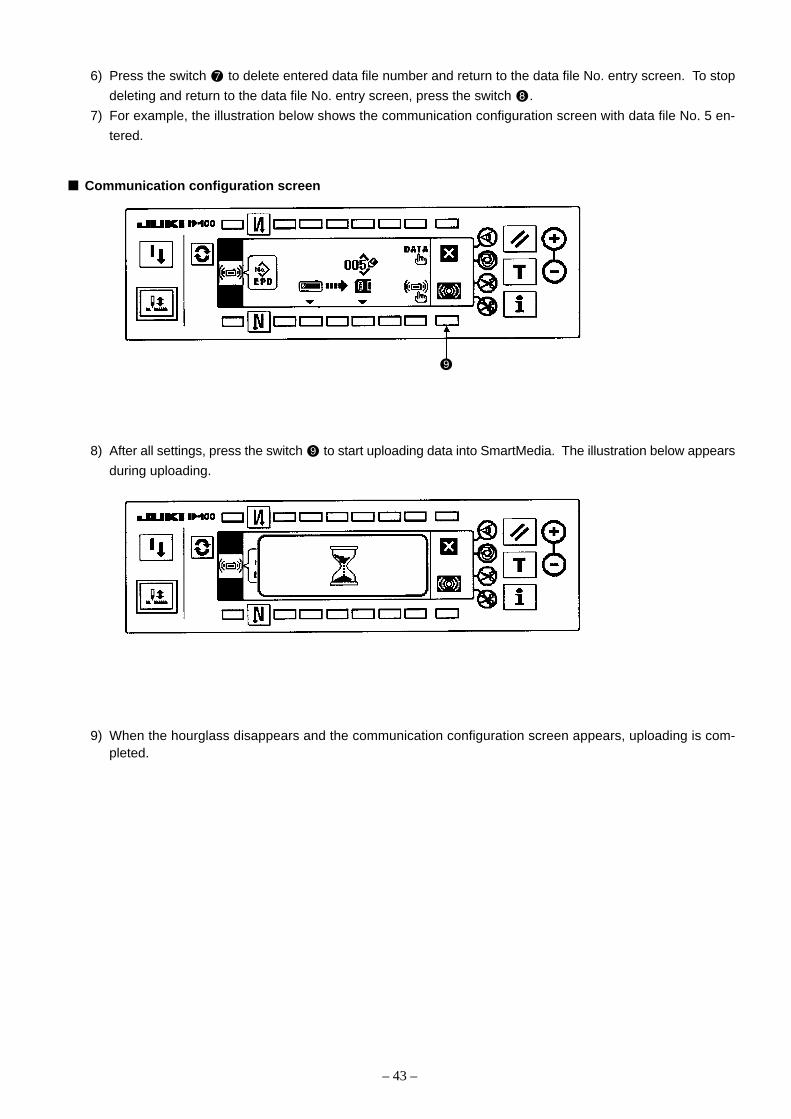
6) Press the switch to delete entered data file number and return to the data file No. entry screen. To stop
deleting and return to the data file No. entry screen, press the switch .
7) For example, the illustration below shows the communication configuration screen with data file No. 5 en-
tered.
Communication configuration screen
8) After all settings, press the switch to start uploading data into SmartMedia. The illustration below appears
during uploading.
9) When the hourglass disappears and the communication configuration screen appears, uploading is com-pleted.

– 44 –
[2] Download of simplified program data
Downloading simplified programs (No. 1 to 4 at once) from SmartMedia to SC-510 provides you with the avail-
ability of simplified programs with more than one sewing machine.
The following explains how to copy simplified programs (No. 1 to 4 at once) for data file No. 5 (parameter
formatted data (EPD)) into a SC-510.
1) Select “parameter formatted data (EPD)” on the data selection screen and select “SmartMedia” ⇒ “operation
panel” on the communication method selection screen to call up the screen below.
Communication configuration screen
2) Press the switch to call up the data file No. entry screen.
Data file No. entry screen

– 45 –
3) Press the switch to enter a data file number. Entered number appears at . After number entry, pressthe switch to return to the communication configuration screen.To delete a data file in SmartMedia, press the switch after entry of the data file number to call up thescreen for confirming data file deleting as shown below.
Screen for confirming data file deleting
4) Press the switch to delete entered data file number and return to the data file No. entry screen. To stop
deleting and return to the data file No. entry screen, press the switch .
5) For example, the illustration below shows the communication configuration screen with data file No. 5 en-tered.
6) After all settings, press the switch to start downloading data into SC-510. The illustration on the previous
page appears during downloading.
– 46 –
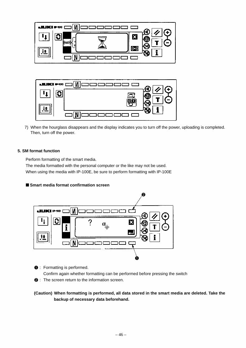
5. SM format function
Perform formatting of the smart media.
The media formatted with the personal computer or the like may not be used.
When using the media with IP-100E, be sure to perform formatting with IP-100E
Smart media format confirmation screen
: Formatting is performed.
Confirm again whether formatting can be performed before pressing the switch
: The screen return to the information screen.
(Caution) When formatting is performed, all data stored in the smart media are deleted. Take the
backup of necessary data beforehand.
7) When the hourglass disappears and the display indicates you to turn off the power, uploading is completed.Then, turn off the power.

– 47 –
(7) Software upgradeTo upgrade the control program for the control box (SC-510), follow the procedure below. Upgrade operation for
the extension board (IPOP board) and operation panel (IP-100E) is performed in the same manner.
1) First, create the folders configured as shown below in a SmartMedia card and store each control program file
(* PRG) in them.
SmartMedia
P R O G
S C 5 1 0
MT******. PRG
I P******. PRG
MA******. PRG
MT******. PRG : Servomotor (SC-510 main body CTL board)
I P******. PRG : Operation panel (IP-100E)
MA******. PRG : IPOP (SC-510 expansion IPOP board)
2) Turn on the power while pressing the switches () and () on the front panel of the control boxsimultaneously, and LED 3 circled with dotted line blinks. If LED3 does not blink, try the operation again.
CTL board LED3
IPOP board

– 48 –
3) The IP-100E operation panel displays the screen as shown below with a beep sound. However, the values
of R-V-L may vary.
4) Press the switch to call up the screen as shown below. The operation panel is selected in the state of
screen opening (operation panel highlighted). Press the switch to select the servomotor (SC-510 main
body [CTL board]) (servomotor highlighted).
: Operation panel (IP-100E)
: IPOP (SC-510 expansion [IPOP board])
: Servomotor (SC-510 main body [CTL board])

– 49 –
5) After selection, press the switch to close the pop-up screen and the screen below appears. (When a
Smart Media card is not loaded, “E011” error is indicated. In such a case, turn off the power and load a Smart
Media card.) Press the switch to select a software version (R-V-L) of the servomotor (SC-510 main body
[CTL boar[) to be updated.
6) After selection, press the switch to start communication (update). A percentage (%) bar graph appears to
indicate how much updating is completed. When the graph indicates 100%, communication is fully com-
pleted and the display that indicated you to turn off the power appears
7) When the display indicates you to turn off the power, do as indicated.
The procedure above completes the updating operation. To start operation with updated software, turn on the
power again.
To update operation panel (IP-100E) or IPOP (SC-510 expansion [IPOP board]), the procedure is the same, but
replace the target in the steps 4) and 5).
(Caution) Never turn off the power during commnucation. In case that you turn off the power during
commnunication for any reason under the process of updating the servomotor (SC-510 main
body [CTL board]) or IPOP (SC-510 expansion [IPOP board]), the screen used in the step 3)
appears by turning on the power Follow the procedure threafter again. When it happens under
the process of updating the operation panel )IP-100E), operation panel (IP-100E) software is
automatically) selected by turning on the power. Then, press the information switch to start
communicaton.
10%0% 100%
Percentage (%) bar graph
Power OFF indication
– 50 –
A
Front coverA
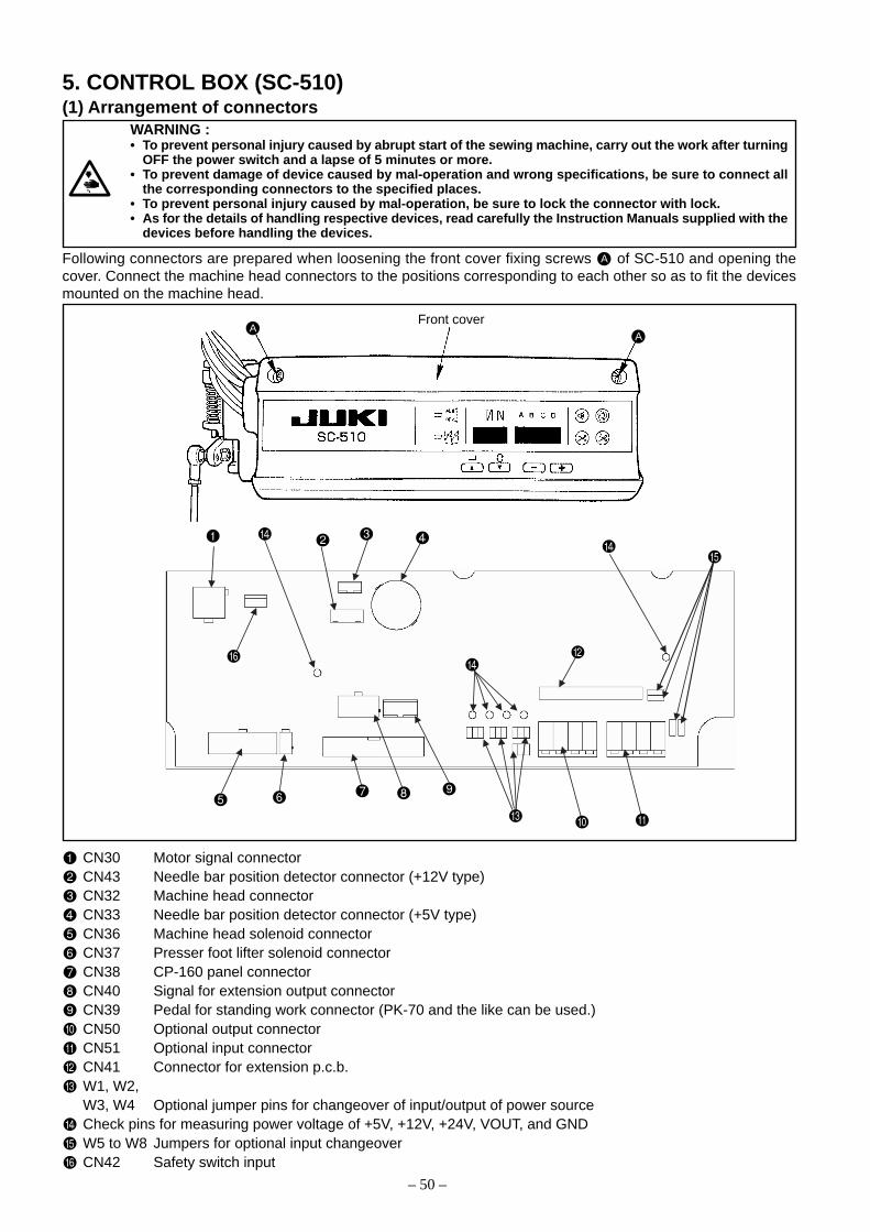
CN30 Motor signal connectorCN43 Needle bar position detector connector (+12V type)CN32 Machine head connectorCN33 Needle bar position detector connector (+5V type)CN36 Machine head solenoid connectorCN37 Presser foot lifter solenoid connectorCN38 CP-160 panel connectorCN40 Signal for extension output connectorCN39 Pedal for standing work connector (PK-70 and the like can be used.)CN50 Optional output connectorCN51 Optional input connectorCN41 Connector for extension p.c.b.W1, W2,W3, W4 Optional jumper pins for changeover of input/output of power sourceCheck pins for measuring power voltage of +5V, +12V, +24V, VOUT, and GNDW5 to W8 Jumpers for optional input changeoverCN42 Safety switch input
5. CONTROL BOX (SC-510)(1) Arrangement of connectors
WARNING :• To prevent personal injury caused by abrupt start of the sewing machine, carry out the work after turning
OFF the power switch and a lapse of 5 minutes or more.• To prevent damage of device caused by mal-operation and wrong specifications, be sure to connect all
the corresponding connectors to the specified places.• To prevent personal injury caused by mal-operation, be sure to lock the connector with lock.• As for the details of handling respective devices, read carefully the Instruction Manuals supplied with the
devices before handling the devices.
Following connectors are prepared when loosening the front cover fixing screws A of SC-510 and opening thecover. Connect the machine head connectors to the positions corresponding to each other so as to fit the devicesmounted on the machine head.
– 51 –
/ switch : Used for determining the contents of setting.When this switch is pressed, flashing stops and the contents of settingare determined.
/ switch : Used for changing the contents of setting.When this switch is pressed, changeable positions flash on and off.By pressing the switch, flashing position shifts in the right direction.
switch : Used for changing the contents of the selected display (flashingsection).When this switch is pressed, the contents of the display increase.
switch : Used for changing the contents of the selected display (flashing section).When this switch is pressed, the contents of the display decrease.
PATTERN SELECTION display : The selected pattern is displayed.
REVERSE STITCHING : Rendered effective when reverse stitching pattern is selected.AT START display “ ” Without reverse stitching display / “ ” Reverse stitching display/
“ ” Double reverse stitching display
REVERSE STITCHING : Rendered effective when reverse stitching pattern is selected.AT END display “ ” Without reverse stitching display / “ ” Reverse stitching display/
“ ” Double reverse stitching display
NUMBER OF STITCHES display : Number of stitches of reverse stitching or overlapped stitching is displayed.
MATERIAL EDGE SENSOR : Lights up when the material edge sensor setting is selected.display Function setting No. 2
ONE-SHOT AUTOMATIC : Lights up when the one-shot automatic stitching is selected.STITCHING display Function setting No. 76
AUTOMATIC : Lights up when the automatic thread trimming by depressing the frontTHREAD TRIMMING display part of the pedal is selected.
Function setting No. 3
THREAD TRIMMING : Lights up when the thread trimming prohibition is selected.PROHIBITION display Function setting No. 9
(2) How to use the standard operation panel
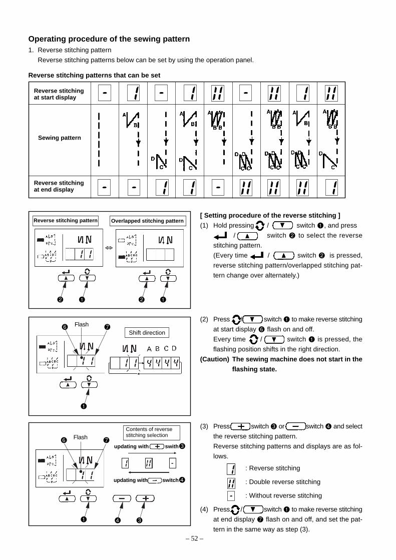
– 52 –
Operating procedure of the sewing pattern1. Reverse stitching pattern
Reverse stitching patterns below can be set by using the operation panel.
Reverse stitching patterns that can be set
Reverse stitchingat start display
Sewing pattern
Reverse stitchingat end display
[ Setting procedure of the reverse stitching ]
(1) Hold pressing / switch , and press
/ switch to select the reverse
stitching pattern.
(Every time / switch is pressed,
reverse stitching pattern/overlapped stitching pat-
tern change over alternately.)
(2) Press / switch to make reverse stitching
at start display flash on and off.
Every time / switch is pressed, the
flashing position shifts in the right direction.
(Caution) The sewing machine does not start in the
flashing state.
(3) Press switch or switch and select
the reverse stitching pattern.
Reverse stitching patterns and displays are as fol-
lows.
: Reverse stitching
: Double reverse stitching
: Without reverse stitching
(4) Press / switch to make reverse stitching
at end display flash on and off, and set the pat-
tern in the same way as step (3).
Flash
Flash
⇔
Reverse stitching pattern Overlapped stitching pattern
Shift direction
Contents of reversestitching selection
updating with switch
updating with swith
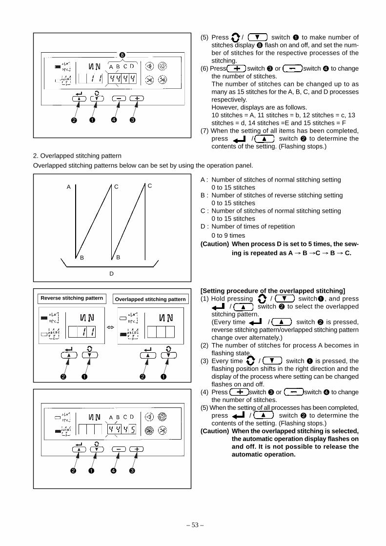
– 53 –
A : Number of stitches of normal stitching setting0 to 15 stitches
B : Number of stitches of reverse stitching setting0 to 15 stitches
C : Number of stitches of normal stitching setting0 to 15 stitches
D : Number of times of repetition0 to 9 times
(Caution) When process D is set to 5 times, the sew-ing is repeated as A → B →C → B → C.
[Setting procedure of the overlapped stitching](1) Hold pressing / switch , and press
/ switch to select the overlappedstitching pattern.(Every time / switch is pressed,reverse stitching pattern/overlapped stitching patternchange over alternately.)
(2) The number of stitches for process A becomes inflashing state.
(3) Every time / switch is pressed, theflashing position shifts in the right direction and thedisplay of the process where setting can be changedflashes on and off.
(4) Press switch or switch to changethe number of stitches.
(5) When the setting of all processes has been completed,press / switch to determine thecontents of the setting. (Flashing stops.)
(Caution) When the overlapped stitching is selected,the automatic operation display flashes onand off. It is not possible to release theautomatic operation.
(5) Press / switch to make number ofstitches display flash on and off, and set the num-ber of stitches for the respective processes of thestitching.
(6) Press switch or switch to changethe number of stitches.The number of stitches can be changed up to asmany as 15 stitches for the A, B, C, and D processesrespectively.However, displays are as follows.10 stitches = A, 11 stitches = b, 12 stitches = c, 13stitches = d, 14 stitches =E and 15 stitches = F
(7) When the setting of all items has been completed,press / switch to determine thecontents of the setting. (Flashing stops.)
2. Overlapped stitching pattern
Overlapped stitching patterns below can be set by using the operation panel.
D
A C C
B B
⇔
Overlapped stitching patternReverse stitching pattern

– 54 –
3. Special settingFor material end sensor function, automatic thread trimming function, one-shot automatic stitching function andthread trimming prohibition function which are displayed in the front panel, it is possible to change the set value bydirectly moving to the function setting mode while the power is turned ON in addition to the normal function settingprocedure.
[ Moving procedure to the function setting mode ](1) Hold pressing / switch , and press
switch to move to the function settingmode.
(Caution) Function setting No. 2 is displayed imme-diately after the changeover.
(2) When returning to the normal mode, press / switch and determine the contents of thesetting.
1) Material end sensor function setting (Function set-ting No. 2)It is rendered effective when connecting the optionalmaterial end sensor.It is possible to change the set value with switch
or switch .0 : Material end sensor function is prohibited.1 : Material end sensor function is effective.
When “1” is selected, material endsensor display lights up when themode has returned to the normalone.
2) Thread trimming operation after material end stopsetting (Function setting No. 3)Press / switch to advance to thefunction setting No. 3.It is possible to change the set value with switch
or switch .0 : Material end stop1 : Automatic thread trimming after detection of
material endWhen “1” is selected, the auto-matic thread trimming displaylights up when the mode is re-turned to the normal one.
3) Number of stitches to stop the sewing machine afterdetection of material end setting (Function settingNo. 4)Press / switch to advance to thefunction setting No. 4.It is possible to change the set value with switch
or switch .Specified number of stitches : 0 to 19 stitches
(Caution) When the specified number of stitches isinsufficient, there is a case where the sew-ing machine cannot stop within the speci-fied number of stitches depending on thespeed of rotation of the sewing machine.
a
a

– 55 –
4) One-shot automatic stitching setting function (Func-tion setting No. 76)Press / switch to advance to thefunction setting No. 76.It is possible to change the set value with switch
or switch .0 : Pedal designated speed is prior.1 : Automatic operation
(Caution) 1. It is rendered effective when the mate-rial end sensor function is set.It is not possible to prohibit the oneshotoperation at the time of the overlappedstitching operation.
2. Speed of rotation is the speed set at thefunction setting No. 38.
When “1” is selected, the oneshotautomatic stitching display lightsup when the mode is returned tothe normal one.
5) Thread trimming prohibition function setting (Func-tion setting No. 9)Thread trimming operation at normal stitching andoverlapped stitching can be prohibited by selectingthe thread trimming prohibition.Press / switch to advance to thefunction setting No. 9.It is possible to change the set value with switch
or switch .0 : Thread trimming is effective.1 : Thread trimming is prohibited.
When “1” is selected, the threadtrimming prohibition display lightsup when the mode is returned tothe normal one.
a
a
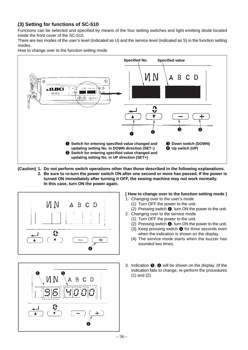
– 56 –
(3) Setting for functions of SC-510Functions can be selected and specified by means of the four setting switches and light emitting diode locatedinside the front cover of the SC-510.There are two modes of the user’s level (indicated as U) and the service level (indicated as S) in the function settingmodes.How to change over to the function setting mode
Specified No. Specified value
Switch for entering specified value changed and Down switch (DOWN)updating setting No. in DOWN direction (SET–) Up switch (UP)Switch for entering specified value changed andupdating setting No. in UP direction (SET+)
(Caution) 1. Do not perform switch operations other than those described in the following explanations.2. Be sure to re-turn the power switch ON after one second or more has passed. If the power is
turned ON immediately after turning it OFF, the sewing machine may not work normally.In this case, turn ON the power again.
[ How to change over to the function setting mode ]1. Changing over to the user’s mode
(1) Turn OFF the power to the unit.(2) Pressing switch , turn ON the power to the unit.
2. Changing over to the service mode(1) Turn OFF the power to the unit.(2) Pressing switch , turn ON the power to the unit.(3) Keep pressing switch for three seconds even
when the indication is shown on the display.(4) The service mode starts when the buzzer has
sounded two times.
3. Indication , will be shown on the display. (If theindication fails to change, re-perform the procedures(1) and (2).
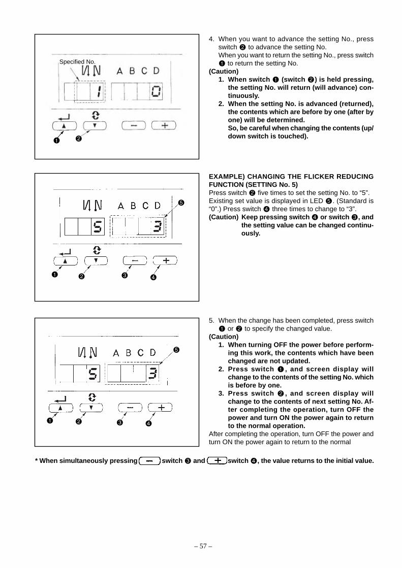
– 57 –
4. When you want to advance the setting No., pressswitch to advance the setting No.When you want to return the setting No., press switch
to return the setting No.(Caution)
1. When switch (switch ) is held pressing,the setting No. will return (will advance) con-tinuously.
2. When the setting No. is advanced (returned),the contents which are before by one (after byone) will be determined.So, be careful when changing the contents (up/down switch is touched).
EXAMPLE) CHANGING THE FLICKER REDUCINGFUNCTION (SETTING No. 5)Press switch five times to set the setting No. to “5”.Existing set value is displayed in LED . (Standard is“0”.) Press switch three times to change to “3”.(Caution) Keep pressing switch or switch , and
the setting value can be changed continu-ously.
5. When the change has been completed, press switch or to specify the changed value.
(Caution)1. When turning OFF the power before perform-
ing this work, the contents which have beenchanged are not updated.
2. Press switch , and screen display willchange to the contents of the setting No. whichis before by one.
3. Press switch , and screen display willchange to the contents of next setting No. Af-ter completing the operation, turn OFF thepower and turn ON the power again to returnto the normal operation.
After completing the operation, turn OFF the power andturn ON the power again to return to the normal
Specified No.
* When simultaneously pressing switch and switch , the value returns to the initial value.

– 58 –
1 Soft start The number of stitches to be sewn at a low speed when the U 0 to 9 64function soft-start function is used at the start of sewing. (Stitches)
0 : Soft-start function is not operative.
2 Material end Material end sensor function (used in case of without panel). U 0/1 64sensor function 0 :Material end detection function is not operative.
1 :After detecting material end, the specified number ofstitches (No. 4) will be sewn, and the sewing machinewill stop.
3 Thread trimming Thread trimming function by material end sensor (used in U 0/1 64function by case of without panel).material end 0 :Automatic thread trimming function after detection ofsensor material end is not operative.
1 :After detecting material end, the specified number of stitches (No. 4) will be sewn, and the sewing machinewill stop and perform automatic thread trimming.
4 Number of Number of stitches for material end sensor (used in case of U 0 to 19 64stitches for without panel). (Stitches)material end Number of stitches from detection of material end to stop ofsensor the sewing machine.
5 Flicker Flicker reducing function (If the hand lamp flickers). U 0 to 3 64reducing 0 :Flicker reducing function is not operative.function 1 :Less effective / 3 : Highly effective
6 Bobbin thread Bobbin thread counting function U 0/1 64counting 0 :Bobbin thread counting function is not operative.function 1 :Bobbin thread counting function is operative.
7 Unit of bobbin Unit of bobbin thread counting down U 0 to 2thread 0 :Count/10 stitchescounting down 1 :Count/15 stitches
2 :Count/20 stitches
8 Number of Sewing speed of reverse feed stitching U 150 to 3000rotation of (rpm)reverse feedstitching
9 Thread Thread trimming prohibiting function (used in case of without U 0/1 64trimming panel).prohibiting 0 :Thread trimming prohibiting function is not operative.function 1 :Thread trimming is prohibited.
(Output of solenoid is prohibited. : Thread trimmer and wiper)
10 Setting of Position of needle bar is specified when the sewing machine U 0/1 64needle bar stops.stop position 0 :Predetermined lowest positionwhen the 1 :Predetermined highest positionsewingmachine stops.
11 Click sound Click sound of key switch mounted on PSC is specified. U 0/1 64of key switch 0 :Click is not operative.mounted on 1 :Click is operative.PSC
12 Optional input/ Changeover of optional switch. U 65output setting
13 Function of Function of prohibiting start of the sewing machine by bobbin U 0 to 2prohibiting start thread countingof the sewing 0 :When counting is out (-1 or less) Function of prohibitingmachine by start of the sewing machine is not operative.bobbin threas 1 : When counting is out (-1 or less) Function of prohibitingcounter start of the sewing machine after thread trimming is operative.
2 :When counting is out (-1 or less), the sewing machinestops once. Function of prohibiting start of the sewingmachine after thread trimming is operative.
14 Sewing counter Counting function of sewing (number of completion of process) U 0 to 2 680 :Sewing counter function is not operative.1 :Sewing counter function is operative.
(for every thread trimming)2: Sewing counter SW input function is operative. (IP-100)
(4) Function setting list (Start level ; U : User’s mode, S : Service mode)
No. Item Description Start level Setting range Indication of function setting
∗ Do not change the set values with asterisk (*) mark as they are functions for maintenance. If the standard set value set at the timeof delivery is changed, it is in danger of causing the machine to be broken or the performance to be deteriorated.(Descriptions of setting in this list are the standard values at the time of delivery.)However, contents of function setting are subject to change for improvement of function and performance without notice.
1 0
2 0
3 0
4 5
5 0
6 1
7 0
∗
8 1 9 0 0
9 0
01 0
11 1
21 0
31 0
41 1
Ref.page
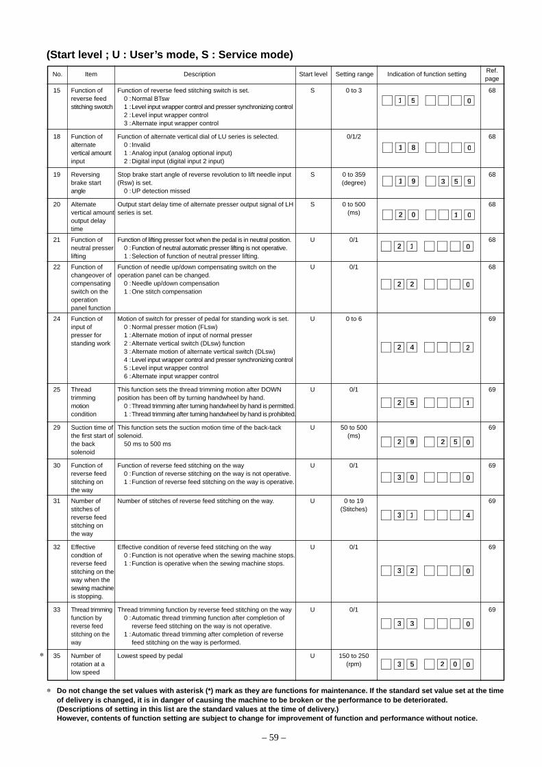
– 59 –
15 Function of Function of reverse feed stitching switch is set. S 0 to 3 68reverse feed 0 :Normal BTswstitching swotch 1 :Level input wrapper control and presser synchronizing control
2 :Level input wrapper control3 :Alternate input wrapper control
18 Function of Function of alternate vertical dial of LU series is selected. 0/1/2 68alternate 0 : Invalidvertical amount 1 :Analog input (analog optional input)input 2 :Digital input (digital input 2 input)
19 Reversing Stop brake start angle of reverse revolution to lift needle input S 0 to 359 68brake start (Rsw) is set. (degree)angle 0 :UP detection missed
20 Altemate Output start delay time of alternate presser output signal of LH S 0 to 500 68vertical amount series is set. (ms)output delaytime
21 Function of Function of lifting presser foot when the pedal is in neutral position. U 0/1 68neutral presser 0 :Function of neutral automatic presser lifting is not operative.lifting 1 :Selection of function of neutral presser lifting.
22 Function of Function of needle up/down compensating switch on the U 0/1 68changeover of operation panel can be changed.compensating 0 :Needle up/down compensationswitch on the 1 :One stitch compensationoperationpanel function
24 Function of Motion of switch for presser of pedal for standing work is set. U 0 to 6 69input of 0 :Normal presser motion (FLsw)presser for 1 :Alternate motion of input of normal presserstanding work 2 :Alternate vertical switch (DLsw) function
3 :Alternate motion of alternate vertical switch (DLsw)4 :Level input wrapper control and presser synchronizing control5 :Level input wrapper control6 :Alternate input wrapper control
25 Thread This function sets the thread trimming motion after DOWN U 0/1 69trimming position has been off by turning handwheel by hand.motion 0 :Thread trimming after turning handwheel by hand is permitted.condition 1 :Thread trimming after turning handwheel by hand is prohibited.
29 Suction time of This function sets the suction motion time of the back-tack U 50 to 500 69the first start of solenoid. (ms)the back 50 ms to 500 mssolenoid
30 Function of Function of reverse feed stitching on the way U 0/1 69reverse feed 0 :Function of reverse stitching on the way is not operative.stitching on 1 :Function of reverse feed stitching on the way is operative.the way
31 Number of Number of stitches of reverse feed stitching on the way. U 0 to 19 69stitches of (Stitches)reverse feedstitching onthe way
32 Effective Effective condition of reverse feed stitching on the way U 0/1 69condtion of 0 :Function is not operative when the sewing machine stops.reverse feed 1 :Function is operative when the sewing machine stops.stitching on theway when thesewing machineis stopping.
33 Thread trimming Thread trimming function by reverse feed stitching on the way U 0/1 69function by 0 :Automatic thread trimming function after completion ofreverse feed reverse feed stitching on the way is not operative.stitching on the 1 :Automatic thread trimming after completion of reverseway feed stitching on the way is performed.
35 Number of Lowest speed by pedal U 150 to 250rotation at a (rpm)low speed
12 0
51 0
81 0
91 953
02 01
22 0
42 2
52 1
92 52 0
03 0
13 4
23 0
33 0
53 02 0
(Start level ; U : User’s mode, S : Service mode)
No. Item Description Start level Setting range Indication of function setting
∗
Ref.page
∗ Do not change the set values with asterisk (*) mark as they are functions for maintenance. If the standard set value set at the timeof delivery is changed, it is in danger of causing the machine to be broken or the performance to be deteriorated.(Descriptions of setting in this list are the standard values at the time of delivery.)However, contents of function setting are subject to change for improvement of function and performance without notice.

– 60 –
36 Number of 20 Number of rotation at the time of thread trimming is set. S 100 to 250 70rotation of (This setting is prior even when number of rotation is lower 5 (rpm)thread trimming than the lowest speed by pedal of No. 35.)
37 Number of Sewing speed at the start of sewing (soft-start)(The max. value U 100 to MAX 64rotation of depends on the number of rotation of the sewing machine head.) (rpm)soft start
38 One-shot One-shot speed (The max. value depends on the number of U 150 to MAX 70speed rotation of the sewing machine head.) (rpm)
39 Pedal stroke Position where the sewing machine starts rotating from pedal U 10 to 50at the start of neutral position (Pedal stroke) (0.1mm)rotation
40 Low speed Position where the sewing machine starts accelerating from U 10 to 100section of pedal neutral position (Pedal stroke) (0.1mm)pedal
41 Starting Position where the cloth presser starts lifting from pedal neutral U -60 to -10position of position (Pedal stroke) (0.1mm)jlifting presserfoot by pedal
42 Sarting Starting position of lowering presser foot U 8 to 50position of Stroke from the neutral position (0.1mm)loweningpresser foot
43 Pedal stroke 2 Position 2 where the thread trimming starts from pedal neutral U -60 to -10for starting position (When the function of lifting presser foot by pedal is (0.1mm)thread trimming provided.) (Pedal stroke)
44 Pedal stroke Position where the sewing machine reaches its highest sewing U 10 to 150for reaching the speed from pedal neutral position (Pedal stroke) (0.1mm)maximumnumber ofrotation
45 Compensation Compensation value of the pedal sensor U -15 to 15of neutral pointof the pedal
46 Auto-lifter Auto-lifter selection S 0/1 70slecting function 0 :Solenoid drive system
1 :Pneumatic drive system
47 Holding time of Limitation time of waiting for lifting solenoid type auto-lifter U 10 to 600 71lifting auto-lifter device
48 Pedal stroke 1 Position where thread trimming starts from pedal neutral position U -60 to -10for starting (Standard pedal) (Pedal stroke) (0.1mm)thread trimming
49 Foot lifter Foot lifter’s lowering time since depressing the pedal U 0 to 250lowering time (ms)
50 Pedal presser PFL type of pedal type is set S 0/1 71lifting function 0 :OFF
1 :ON
51 Compensation of Compensation of starting the solenoid for reverse feed stitching U -36 to 36 71solenoid-on when reverse feed stitching at the start of sewing is performed. (10°)trimming of reversefeed stitching atthe start of sewing
52 Compensation of Compensation of releasing the solenoid for reverse feed stitching U -36 to 36 71solenoid-off when reverse feed stitching at the start of sewing is performed. (10°)trimming of reversefeed stitching atthe start of sewing
53 Compensation of Compensation of releasing the solenoid for reverse feed stitching U -36 to 36 71solenoid-off when reverse feed stitching at the end of sewing is performed. (10°)trimming of reversefeed stitching atthe end of sewing
7 64 0
8 – 34 5
1 15 0
2 15 6
3 15 8
93 3 0
04 6 0
1 –4 2 1
24 1 0
3 –4 5 1
4 14 5 0
54 0
64 0
05 0
8 23 05 0
73 08 0
63 001
9 1 44 0
(Start level ; U : User’s mode, S : Service mode)
No. Item Description Start level Setting range Indication of function setting
∗
Ref.page
∗ Do not change the set values with asterisk (*) mark as they are functions for maintenance. If the standard set value set at the timeof delivery is changed, it is in danger of causing the machine to be broken or the performance to be deteriorated.(Descriptions of setting in this list are the standard values at the time of delivery.)However, contents of function setting are subject to change for improvement of function and performance without notice.
∗
∗
∗
∗
∗

– 61 –
54 Motor pulley Effective diameter of pulley to be used for motor is set. S 50.0 to 140.0 72effective 5 (mm)jdiameter
55 Foot lift after Function of lifting presser foot at the time of (after) thread trimming U 0/1 72thread 0 :Not provided with the function of lifting presser foot aftertrimming thread trimming
1 :Provided with the function of lifting presser foot automaticallyafter thread trimming
56 Bobbin thread Function of reverse revolution to lift the needle at the time of U 0/1 72remaining (after) thread trimmingamount 0 :Not provided with the function of reverse revolution to liftdetection the needle after thread trimmingfunction 1 :Provided with the function of reverse revolution to lift the
needle after thread trimming
57 Function of Function of bobbin thread remaining amount detection device S 0 to 72bobbin thread is set.remaining 0 : Invalidamount 1 to : Valid function is selected.detection
58 Function of Function of holding predetermined upper/lower position of the U 0 to 3 72holding needle barpredetermined 0 :Not provided with the function of holding predeterminedupper/lower upper/lower position of the needle barposition of the 1 :Provided with the function of holding predetermined upper/needle bar lower position of the needle bar (holding force is weak.)
2 :Provided with the function of holding predetermined upper/lower position of the needle bar (holding force is medium.)
3 :Provided with the function of holding predetermined upper/lower position of the needle bar (holding force is strong.)
59 Function of This function can specify the sewing speed of reverse feed U 0/1 73Auto/Manual stitching at the start of sewing.changeover 0 :The speed will depend on the manual operation by pedal,of reverse feed etc.stitching at the 1 :The speed will depend on the specified reverse feedstart of sewing stitching speed (No. 8).
60 Function of stop Function at the time of completion of reverse feed stitching U 0/1 73immediately at the start of sewingafter reverse 0 :Not provided with the function of temporary stop of thefeed atitching sewing machine at the time of completion of reverse feedat the start of stitching at the start of sewingsewing 1 :Provided with the function of temporary stop of the sewing
machine at the time of completion of reverse feed stitchingat the start of sewing.
61 Bobbin thread Air blow output time when thread trimming with bobbin thread S 0 to 2000 73remaining remaining amount detection device is set. (ms)amount detectionair blow outputtime
63 Tie stitch Stop time of respective corners of start, end and overlapped S 0 to 1000 73adjustment stitching is set. (ms)function
64 Change-over Initial speed when starting reverse feed stitching at the sewing U 0 to 250speed of EBT end (rpm)(end bak tack)
65 Selection of Selection of thread trimmer or additional device (UT or the like) S 73thread trimmer TrM : Thread trimming functionand additional UT1 : Additional device 1deveice function UT2 : Additional device 2
66 Simplified Setting of simplified program is performed. S 77program setting
67 Auto hemmer Selection of auto hemmer control is performed. S 0/1 77control 0 :Control 1changeover 1 :Control 2
65 0
85 0
95 1
06 0
46 81 0
45 005
75 0
16 005
36 01
56 nUF
66 orP
76 0
55 1
(Start level ; U : User’s mode, S : Service mode)
No. Item Description Start level Setting range Indication of function setting
∗
Ref.page
∗ Do not change the set values with asterisk (*) mark as they are functions for maintenance. If the standard set value set at the timeof delivery is changed, it is in danger of causing the machine to be broken or the performance to be deteriorated.(Descriptions of setting in this list are the standard values at the time of delivery.)However, contents of function setting are subject to change for improvement of function and performance without notice.

– 62 –
68 Prohibition of Start of sewing machine is prohibited at the time of auto hemmer S 0/1 77start with control without clothmaterial end 0 : Invalidsensor of auto 1 :Prohibitedhemmer control
69 Selection of Speed after detection of material end sensor of auto hemmer S 0/1 77speed control control is set.method after 0 :Depressing amount of pedaldetection of 1 :Set speed (motion at the set speed of No. 38)material endsensor of autohemmer control
70 Number of Number of stitches which makes invalid material end sensor S 0 to 500 77stitches of detection with auto hemmer control is set. (0.5 stitches)invalid materialend sensorauto hemmercontrol
72 Clutch motor Clutch motor control type is selected. S 0/1 77function 0 :OFF
1 :ON
73 Retry function This function is used when needle cannot pierce materials . U 0/1 780 :Normal1 :Retry function is provided.
74 With/without This function sets with or without the MF thread trimming device U 0/1 78MF thread 0 :Withouttrimming device 1 :With
75 Rotating Normal rotating direction of motor U 0/1derection of 0 :Clockwisemotor 1 :Counterclockwise
76 One-shot One-shot automatic stitching up to end of material is performed. U 0/1 78function up to (Used in case of without panel)end of material 0 :Without one-shot function
1 :With one-shot function
84 Presser lifter Suction motion time of presser lifter solenoid U 50 to 500solenoid initial 50 to 500 ms (ms)motion suctiontime
85 Reverse feed Holding time of start speed of reverse feed stitching at the S 0 to 250 78stitching at the endo of sewing is set. 10 (ms)end of sewingstart time
86 Waiting time of Delay time from UP stop to start of reverse revolution at the S 0 to 250 78start of reverse time of control of reverse revolution to lift needle is set. 10 (ms)revolution to liftneedle
87 Function of Pedal curve is selected. (Improving pedal inching operation) U 0/1/2 78pedal curveselection
89 Tension It is effective in combination with the machine head provided U 0/1release with tension release function.function 0 :Tension release function is ineffective.
1 :Tension release function is effective.
90 Initial UP stop Automatic UP stop function is set immediately after turning S 0/1 78position move ON the power.function 0 :OFF
1 :ON
57 1
67 0
48 52 0
58 01
68 01
78 0
98 0
09 0
47 1
27 0
37 1
(Start level ; U : User’s mode, S : Service mode)
No. Item Description Start level Setting range Indication of function setting
∗
Ref.page
∗ Do not change the set values with asterisk (*) mark as they are functions for maintenance. If the standard set value set at the timeof delivery is changed, it is in danger of causing the machine to be broken or the performance to be deteriorated.(Descriptions of setting in this list are the standard values at the time of delivery.)However, contents of function setting are subject to change for improvement of function and performance without notice.
86 0
96 0
07 0
Number of rotations(rpm)
Pedal stroke(mm)
2
1
0
∗
∗

– 63 –
91 Function Function of compensating stitching when turning handwheel U 0/1prohibiting by hand at the time of completion of constant-dimension stitchingcompensation 0 :Function of compensating stitching is effective.operation after 1 :Function of compensating stitching is prohibited.turninghandwhwwl byhand
92 Function of Function to reduce speed at the time of completion of reverse U 0/1 79reducing speed feed stitching at the start of sewing.of reverse feed 0 :Speed is not reduced.stitching at the 1 :Speed is reduced.start of sewing
93 Function added Operation of needle up/down compensating switch is changed U 0/1 79to needle up/ after turning ON the power or thread trimming.down 0 :Normal (needle up/down compensating stitching only)compensating 1 :One stitch compensating stitching is performed only whenswitch aforementioned changeover is made. (Upper stop / upper
stop)
94 Test display Display function of input data is set. S 0/1 79mode 0 :OFF
1 :ON
95 Selection of the This function sets the machine head used. Ssewing For the details, refer to the data, which are separately describedmachine head on the sheet of Selecting procedure of the machine head
with SC-510 (40027864).
96 Setting of max. Max. number of rotation of the sewing machine head can be set. U 150 to MAX 79number of * Setting varies in accordance with resistance pack to be (rpm)rotation of the connected.sewingmachine head
100 2-pitch output You can enable or disable 2-pitch output during reverse stitching U 0/1during reverse at the start/end of sewing.stitching at 0: Disabledstart/end of 1: Enabledsewing
101 2-pitch inverse You can enable or disable 2-pitch inverse output in response to U 0/1output during alternate vertical output.alternate 0: Disabledvertical output 1: Enabled
69 0 04 0
59
(Start level ; U : User’s mode, S : Service mode)
No. Item Description Start level Setting range Indication of function setting
∗
Ref.page
∗ Do not change the set values with asterisk (*) mark as they are functions for maintenance. If the standard set value set at the timeof delivery is changed, it is in danger of causing the machine to be broken or the performance to be deteriorated.(Descriptions of setting in this list are the standard values at the time of delivery.)However, contents of function setting are subject to change for improvement of function and performance without notice.
19 1
29 0
39 0
49 0
1 00 0
1 10 0

– 64 –
(5)Detailed explanation of selection of functions
11111 Selection of the soft-start function (Function setting No. 1)The needle thread may fail to interlace with the bobbin thread at the start of sewing when the stitching pitch(stitch length) is small or a thick needle is used. To solve such problem, this function (called “soft-start”) is usedto limit the sewing speed, thereby assuring successful formation of the starting stitches.
0 : The function is not selected.
1 to 9 : The number of stitches to be sewn under the soft-start mode.
The sewing speed limited by the soft-start function can be changed. (Function setting No. 37)
Data setting range
100 to MAX rpm <50 rpm>
22222 Material end sensor (ED : optional) function (Function setting No. 2 to 4)
This function is possible when the material end sensor (ED) is attached.As for the details, refer to the instruction manual for the material end sensor.(Caution) Setting will be invalid when the material end sensor is not attached, or CP-160 is connected.
33333 Flicker reducing function (Function setting No. 5)
The function reduces flickering of the hand lamp at the start of sewing. The higher the set value increases, the
more effective the function will work.
Setting range
0 to 3
0 : Flicker reducing function does not work. to 3 : Flickering is effectively reduced.
(Caution) The more effective the flicker reducing function works (the more the set value is made), thelower the start-up speed of the sewing machine will become.
44444 Bobbin thread counting function (Function setting No. 6)When the control panel (CP-160) is used, the function subtracts from the predetermined value and indicates theused amount of bobbin thread.For the details, refer to the instruction manual for the control panel.(Caution) If “0” is set, the LCD indication on the control panel will go out and the bobbin thread count-
ing function will be invalid.
55555 Thread trimming prohibiting function (Function setting No. 9)This function turns OFF thread trimming solenoid output and wiper solenoid output when thread trimming isactuated. [If the control panel (CP-160) is used with the sewing machine, this function will work in accordancewith the function setting on the control panel.]By this function, separate sewing material can be spliced and sewn without trimming thread.
0 : off Thread trimming is operative. (thread can be trimmed).
1 : on Thread trimming is inoperative. (thread can not be trimmed).
66666 Setting of the needle bar stop position when the sewing machine stops (Function setting No. 10)
The position of the needle bar when the pedal is in its neutral position is specified.
0 : Down The needle bar stops in the lowest position of its stroke.
1 : Up The needle bar stops in the highest position of its stroke.
(Caution) If the stop position of the needle bar is set to the highest position, the thread trimming actionwill be taken after the needle bar comes down once to the lowest position.
77777 Sound of click of the key switch mounted on the PSC box (Function setting No. 11)This function selects whether the sound is effective or ineffective when operating the four key switches mountedon the PSC box.
0 : off The sound of click is ineffective.
1 : on The sound of click is effective.
1 0
7 83 00
5 0
9 0
01 0
11 1

– 65 –
88888 Selection of the optional input/output function (Function setting No. 12)
Operation keys array
1. Select function No. 12 with the operating procedures described in theitem of how to change over the function setting mode (1) to (4).Select the items of “End”, “in” and “ouT” with keys and .
[When “in” is selected]The port Nos. are displayed in the left 3 digits. Designate the input port withkey or . Designate the function of input port with key or .The function code and the abbreviation are alternately displayed in the 4-digit LED.(For the relation between signal input No. and connector pin array,refer to the separate list.)
[When “ouT” is selected]The port Nos. are displayed in the left 3 digits. Designate the output port withkey or . Designate the function of output port with key or .The function code and the abbreviation are alternately displayed in the 4-digit LED. (For the relation between signal input No. and connector pin array,refer to the separate list.)
(Caution) Note that the voltage used in output function should not exceed the voltage set with W1 andW2.
* Example) Setting the thread trimming function to the optional input port 1
1. Select function No. 12 with the operating procedures described in the
item of how to change over the function setting mode (1) to (4).
2. Select the item of “in” with keys and .
3. Select the port of 901 with key .
4. Select the thread trimming function, “TSW” with keys and .
5. Determine the thread trimming function, “TSW” with key .
6. Set ACTIVE of the signal with keys and .
Set the display to “L” when the signal is “Low” and performing thread
trimming, and set the display to “H” when the signal is “High” and per-
forming thread trimming.
7. Determine the aforementioned function with key .
8. Finish the optional input with key .
9. Select the item of “End” with keys and to return to the function
setting mode.
* For the other optional function, it is possible to program simple input/output sequence control.
1 2 O P T
09 0 E n d
i n
o u T
***9 0 1
<?
9 0 8
***9 1 1
<?
9 1 8
TPO1 2
n9 i0 0
pon9 0 1
W19 0 T
L 4
S
[\Lighting alternately
419 0 L
H 4
[\
0 2 n o p
09
9
0 i n
dnE
Optional input 1 to8 are displayed
Optional input 1 to8 are displayed

– 66 –
Input function list
Abbreviation Function item Remarks
0 nop No function (Standard setting)1 HS Needle up / down compensating Every time the switch is pressed, normal feed stitching by half
stitching stitch is performed. (Same operation as that of up / downcompensating stitching switch on the panel.)
2 bHS Back compensating stitching Reverse feed stitching is performed at low speed while theswitch is held pressing. (It is effective only when constantdimension sewing pattern is selected with the CP-160.)
3 Ebt Function of canceling once reverse By depressing the back part of the pedal after pressing thefeed stitching at the end of sewing switch, operation of reverse feed stitching is canceled once.
4 TSW Thread trimming function This function is actuated as the thread trimming switch.5 FL Presser foot lifting function This function is actuated as the foot lifter switch.6 oHS One stitch compensating stitching Every time the switch is pressed, one stitch stitching
operation is executed.7 SEbt Function of cancel of reverse feed By operating the optional switch, ineffective/effective can be
stitching at start/end alternately changed over.8 PnFL Presser lifting function when pedal Every time the switch is pressed, the function whether
is neutral automatically lifting the presser foot when the pedal is neutralor not can be selected.
9 Ed Material edge sensor input This function works as the input signal of material edge sensor.10 LinH Function of prohibiting depressing Rotation by pedal is prohibited.
front part of pedal11 TinH Function of prohibiting thread Output of thread trimming is prohibited.
trimming output12 LSSW Low speed command input This function works as low speed switch for standing sewing machine.13 HSSW High speed command input This function works as high speed switch for standing sewing machine.14 USW Needle lifting function UP stop motion is performed when switch is pressed duringDOWN stop.15 rSW Reverse revolution to lift needle Brake stop motion by reverse revolution is performed at specified
function angle when switch is pressed during DOWN stop16 SFSW Safety switch input Rotation is prohibited.17 MES Thread trimmer knife sensor input This function works as input signal of thread trimmer knife sensor.18 AUbT Cancel of automatic reverse feed Every time the switch is pressed, cancel or addition of reverse
stitching/input of addition switch feed stitching at start or end is performed.19 vErT Alternate vertical amount change Every time the switch is pressed, alternate vertical amount
panel switch input change output is inversed.20 vSW Alternate vertical amount change Alternate vertical amount change output is performed as long
knee switch input as the switch is pressed.21 2PiT 2-pitch alternate input Two-pitch output is reversed every time the SW is pressed.22 2PSW 2-pitch momentary switch input Two-pitch output is enabled during the SW is pressed.23 0SSW One-shot speed command switch input The one-shot speed command is enabled during SW is pressed.
Functioncode
Output function list
Abbreviation Function item Remarks
0 nop No function (Standard setting) *1 TrM Thread trimming output Output of thread trimming signal *2 WP Thread wiper output Output of thread wiper signal *3 TL Thread release output Output of thread release signal *4 FL Presser lifter output Output of presser lifting signal *5 bT Reverse feed stitching output Output of reverse feed stitching signal *6 Ebt EBT cancel monitor output State of one time cancel of reverse feed stitching at end
function is output.7 SEbt Reverse feed stitching at start/ State of cancel of reverse feed stitching at start/end is output.
end cancel monitor output8 AUbt Automatic reverse feed stitching State of cancel or addition of automatic reverse feed stitching
cancel/addition monitor output is output.9 vErT Alternate vertical amount change Output of alternate vertical amount change signal
(monitor) output10 SSTA Sewing machine stop state output Sewing machine stop state is output.
11 2PiT 2-pich output 2-pitch signal output is enabled.
Functioncode
* Magnet output does not work when they are used as optional.(Caution) Note that the voltage used in output function should not exceed the voltage set with W1 and W2.
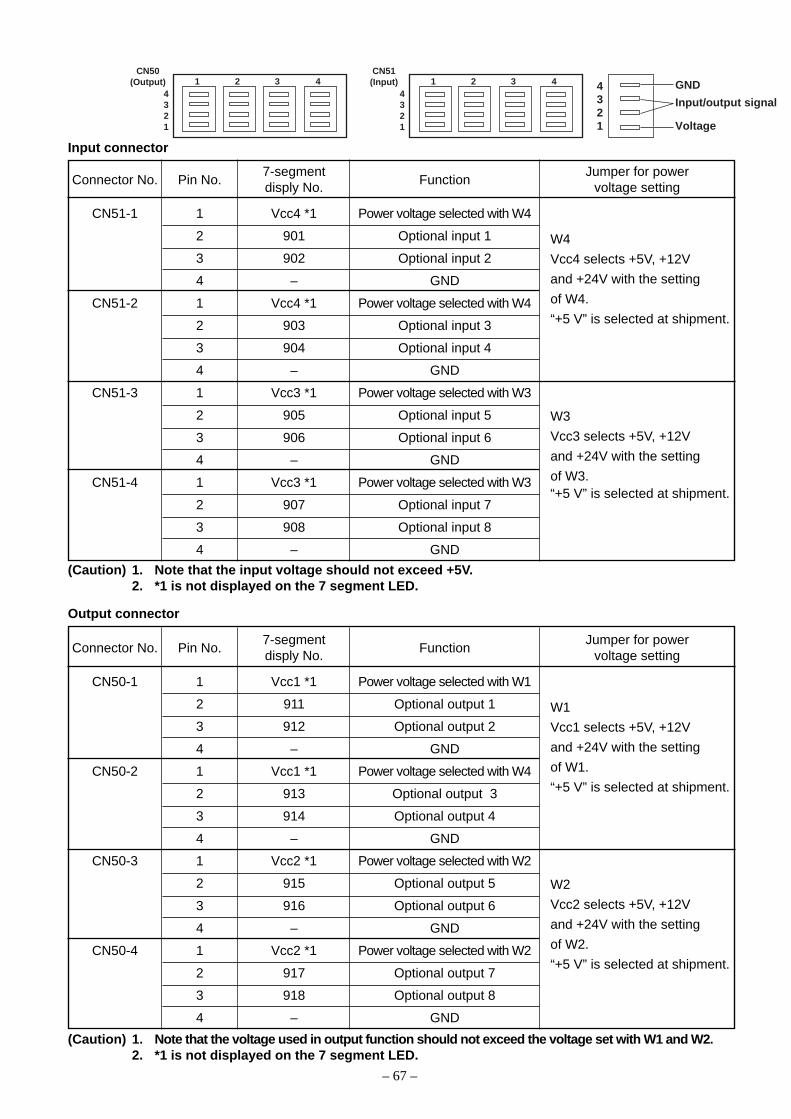
– 67 –
1 2 3 4CN50
(Output)4321
1 2 3 4CN51(Input)
4321
4321
GND
Input/output signal
Voltage
Input connector
Connector No. Pin No. Function
CN51-1 1 Vcc4 *1 Power voltage selected with W4
2 901 Optional input 1
3 902 Optional input 2
4 – GND
CN51-2 1 Vcc4 *1 Power voltage selected with W4
2 903 Optional input 3
3 904 Optional input 4
4 – GND
CN51-3 1 Vcc3 *1 Power voltage selected with W3
2 905 Optional input 5
3 906 Optional input 6
4 – GND
CN51-4 1 Vcc3 *1 Power voltage selected with W3
2 907 Optional input 7
3 908 Optional input 8
4 – GND
7-segmentdisply No.
Jumper for powervoltage setting
W4
Vcc4 selects +5V, +12V
and +24V with the setting
of W4.
“+5 V” is selected at shipment.
W3
Vcc3 selects +5V, +12V
and +24V with the setting
of W3.“+5 V” is selected at shipment.
(Caution) 1. Note that the input voltage should not exceed +5V.2. *1 is not displayed on the 7 segment LED.
Output connector
Connector No. Pin No. Function
CN50-1 1 Vcc1 *1 Power voltage selected with W1
2 911 Optional output 1
3 912 Optional output 2
4 – GND
CN50-2 1 Vcc1 *1 Power voltage selected with W4
2 913 Optional output 3
3 914 Optional output 4
4 – GND
CN50-3 1 Vcc2 *1 Power voltage selected with W2
2 915 Optional output 5
3 916 Optional output 6
4 – GND
CN50-4 1 Vcc2 *1 Power voltage selected with W2
2 917 Optional output 7
3 918 Optional output 8
4 – GND
7-segmentdisply No.
Jumper for powervoltage setting
W1
Vcc1 selects +5V, +12V
and +24V with the setting
of W1.
“+5 V” is selected at shipment.
W2
Vcc2 selects +5V, +12V
and +24V with the setting
of W2.
“+5 V” is selected at shipment.
(Caution) 1. Note that the voltage used in output function should not exceed the voltage set with W1 and W2.2. *1 is not displayed on the 7 segment LED.

– 68 –
99999 Sewing counting function (Function setting No. 14)The function counts up every time thread trimming is completed and counts the number of completion of thesewing process.This can be realized together with the CP-160 (IP-100) control panel. Refer to the explanation of the controlpanel.
0 : off Sewing counting function is inoperative.
1 : on Sewing counter function is operative (for every thread trimming)
2 : on External sewing counter SW input (IP-100)
00000 Function of reverse feed stitching switch (Function setting No. 15)
Function of reverse feed stitching switch is selected.
0 : Reverse feed stitching function of normal operation used with lockstitch machine, and the like1 : Level input wrapper control and presser synchronizing control2 : Level input wrapper control3 : Alternate input wrapper control
!!!!! Alternate vertical amount input function (Function setting No. 18)
Function of alternate vertical dial of LU series is selected.
0 : Function not selected1 : Analog input (Analog input of DL dial from optional input connector CN51 4-
2 pin is possible. It corresponds with DL dial of LU-22* series.)2 : Digital input (DL dial input function of digital input from optional input connector
CN51 4-1 and 4-2 pins is possible. It corresponds with DL dial of LU-15*series.
@@@@@ Reversing brake start angle (Function setting No. 19)Brake start angle of function of reverse revolution to lift needle after thread trimming can be set. Set value setsthe angle from position of UP detection missed.
0 : Invalid (Brake works from position of UP detection missed.)Setting range 1 to 359 [degree]1 to 359 : Brake works after rotating up to the set angle.
As to angle : Angle here means that the angle is that of direction of the normal rotation from missing of UPdetection when the sewing machine rotates in the normal direction.
##### Alternate vertical amount output delay time (Function setting No. 20)Delay time from pressing alternate vertical presser switch of LU series to outputting of alternate vertical outputsignal is set.
Setting range : 0 to 500 [mS]
$$$$$ Neutral automatic presser lifting function (with AK device only) (Function setting No. 21)This function can automatically lift the presser foot when the pedal is in the neutral position.Automatic lifting time of the pedal depends on the automatic lifting time after thread trimming and when thepresser foot is automatically lowered, it is automatically lifted at the second neutral position after it has come offthe neutral position once.
0 : off Function of neutral automatic presser lifting is not operative.1 : on Selection of function of neutral automatic presser lifting
%%%%% Function of changeover of compensating switch on the operation panel function (Function setting No. 22)Function of compensation switch on the operation panel of CP-160 can be changed over to needle up / downcompensating stitching or one stitch compensating stitching.
0 : Needle up / down compensating stitching
1 : One stitch compensating stitching
11 4
01 5
01 8
9531 9
012 0
02 1
02 2
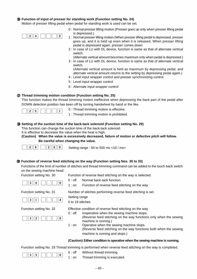
– 69 –
((((( Function of reverse feed stitching on the way (Function setting Nos. 30 to 33)
Functions of the limit of number of stitches and thread trimming command can be added to the touch back switchon the sewing machine head.Function setting No. 30 Function of reverse feed stitching on the way is selected.
0 : off Normal back-tack function
1 : on Function of reverse feed stitching on the way
Function setting No. 31 Number of stitches performing reverse feed stitching is set.
Setting range
0 to 19 stitches
Function setting No. 32 Effective condition of reverse feed stitching on the way0 : off Inoperative when the sewing machine stops.
(Reverse feed stitching on the way functions only when the sewingmachine is running.)
1 : on Operative when the sewing machine stops.(Reverse feed stitching on the way functions both when the sewingmachine is running and stops.)
(Caution) Either condition is operative when the sewing machine is running.
Function setting No. 33 Thread trimming is performed when reverse feed stitching on the way is completed.
0 : off Without thread trimming
1 : on Thread trimming is executed.
03 0
43 1
03 2
03 3
^ Function of input of presser for standing work (Function setting No. 24)Motion of presser lifting pedal when pedal for standing work is used can be set.
0 : Normal presser lifting motion (Presser goes up only when presser lifting pedalis depressed.)
1 : Normal presser lifting motion (When presser lifting pedal is depressed, pressergoes up, and it is held up even when it is released. When presser liftingpedal is depressed again, presser comes down.
2 : In case of LU with DL device, function is same as that of alternate verticalswitch.(Alternate vertical amount becomes maximum only when pedal is depressed.)
3 : In case of LU with DL device, function is same as that of alternate verticalswitch.(Alternate vertical amount is held as maximum by depressing pedal, andalternate vertical amount returns to the setting by depressing pedal again.)
4 : Level input wrapper control and presser synchronizing control5 : Level input wrapper control
6 : Alternate input wrapper control
&&&&& Thread trimming motion condition (Function setting No. 25)This function makes the thread trimming motion ineffective when depressing the back part of the pedal afterDOWN detection position has been off by turning handwheel by hand or the like.
0 : Thread trimming motion is effective.
1 : Thread trimming motion is prohibited.
***** Setting of the suction time of the back-tack solenoid (Function setting No. 29)This function can change the suction time of the back-tack solenoid.It is effective to decrease the value when the heat is high.(Caution) When the value is excessively decreased, failure of motion or defective pitch will follow.
Be careful when changing the value.
Setting range : 50 to 500 ms <10 / ms>
22 4
12 5
02 9 2 5
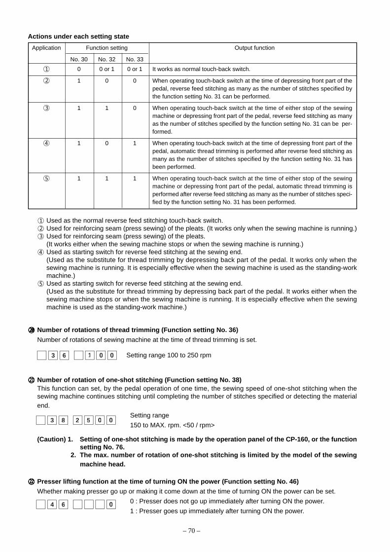
– 70 –
Actions under each setting state
Application Function setting Output function
No. 30 No. 32 No. 33
1 0 0 or 1 0 or 1 It works as normal touch-back switch.
2 1 0 0 When operating touch-back switch at the time of depressing front part of thepedal, reverse feed stitching as many as the number of stitches specified bythe function setting No. 31 can be performed.
3 1 1 0 When operating touch-back switch at the time of either stop of the sewingmachine or depressing front part of the pedal, reverse feed stitching as manyas the number of stitches specified by the function setting No. 31 can be per-formed.
4 1 0 1 When operating touch-back switch at the time of depressing front part of thepedal, automatic thread trimming is performed after reverse feed stitching asmany as the number of stitches specified by the function setting No. 31 hasbeen performed.
5 1 1 1 When operating touch-back switch at the time of either stop of the sewingmachine or depressing front part of the pedal, automatic thread trimming isperformed after reverse feed stitching as many as the number of stitches speci-fied by the function setting No. 31 has been performed.
))))) Number of rotations of thread trimming (Function setting No. 36)
Number of rotations of sewing machine at the time of thread trimming is set.
Setting range 100 to 250 rpm
qqqqq Number of rotation of one-shot stitching (Function setting No. 38)This function can set, by the pedal operation of one time, the sewing speed of one-shot stitching when thesewing machine continues stitching until completing the number of stitches specified or detecting the materialend.
Setting range
150 to MAX. rpm. <50 / rpm>
(Caution) 1. Setting of one-shot stitching is made by the operation panel of the CP-160, or the functionsetting No. 76.
2. The max. number of rotation of one-shot stitching is limited by the model of the sewingmachine head.
wwwww Presser lifting function at the time of turning ON the power (Function setting No. 46)
Whether making presser go up or making it come down at the time of turning ON the power can be set.
0 : Presser does not go up immediately after turning ON the power.
1 : Presser goes up immediately after turning ON the power.
003 8 2 5
1 Used as the normal reverse feed stitching touch-back switch.2 Used for reinforcing seam (press sewing) of the pleats. (It works only when the sewing machine is running.)3 Used for reinforcing seam (press sewing) of the pleats.
(It works either when the sewing machine stops or when the sewing machine is running.)4 Used as starting switch for reverse feed stitching at the sewing end.
(Used as the substitute for thread trimming by depressing back part of the pedal. It works only when thesewing machine is running. It is especially effective when the sewing machine is used as the standing-workmachine.)
5 Used as starting switch for reverse feed stitching at the sewing end.(Used as the substitute for thread trimming by depressing back part of the pedal. It works either when thesewing machine stops or when the sewing machine is running. It is especially effective when the sewingmachine is used as the standing-work machine.)
0013 6
04 6

– 71 –
eeeee Holding time of lifting presser foot (Function setting No. 47)Solenoid type presser foot lifter (No. 46 0) can adjust the holding time control of lifting presser foot.This function automatically lowers the presser foot when the time set with the setting No. 47 has passed afterlifting the presser foot.When the pneumatic type presser foot lifter (No. 46 1) is selected, the holding time control of lifting presser footis limitless regardless of the set value.
Setting range10 to 600 sec <10 / sec>
rrrrr Pedal presser lifting function (Function setting No. 50)
Pedal type setting can be changed. Selection of conventional PFL and KFL types can be performed.
0 : Function is same as conventional KFL type.1 : Function is same as conventional PFL type.
Set value 1 : PFL is the standard. For PFL type in the standard state, the amount of depressing back part of pedalto make thread trimming motion is large (position of thread trimming motion is deep) since there is an auto-liftersection.For this reason, if you feel that the work is hard, setting to KFL type is recommended.By setting to KFL type, thread trimming motion is performed at a shallow position when depressing the back partof pedal.
ttttt Compensation of timing of the solenoid for reverse feed stitching (Function setting No. 51 to 53)When the normal and reverse feed stitches are not uniform under the automatic reverse feed stitching action,this function can change the ON / OFF timing of the solenoid for back tack and compensate the timing.1 Compensation of on-timing of solenoid for reverse feed stitching at the start of sewing (Function setting No. 51)
On-timing of solenoid for reverse feed stitching at the start of sewing can be compensated by the unit ofangle.
Adjusting range
– 36 to 36 <1 / 10°>
2 Compensation of off-timing of solenoid for reverse feed stitching at the start of sewing (Function setting No. 52)
Off-timing of solenoid for reverse feed stitching at the start of sewing can be compensated by the unit of angle.
Adjusting range
– 36 to 36 <1 / 10°>
* When the point before 1stitch is regarded as 0°,compensation is pos-sible by 360° (1 stitch) infront and in the rear.
360°180°
0°-180°-360°
-360°-180°0°180°360°
064 7
015 1
615 2
05 0
Set value Compensation angle Number of stitches of compensation
–36 –360° –1
–18 –180° –0.5
0 0° 0
18 180° 0.5
36 360° 1
Set value Compensation angle Number of stitches of compensation
–36 –360° –1
–18 –180° –0.5
0 0° 0
18 180° 0.5
36 360° 1
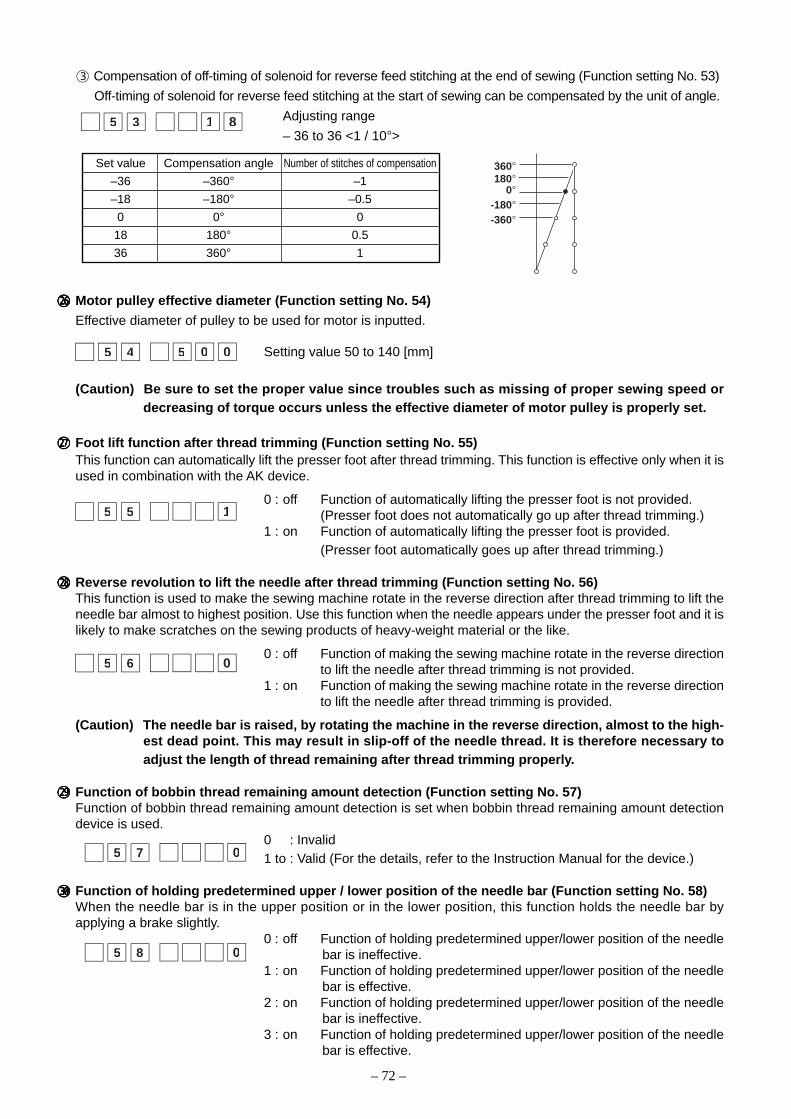
– 72 –
yyyyy Motor pulley effective diameter (Function setting No. 54)
Effective diameter of pulley to be used for motor is inputted.
Setting value 50 to 140 [mm]
(Caution) Be sure to set the proper value since troubles such as missing of proper sewing speed ordecreasing of torque occurs unless the effective diameter of motor pulley is properly set.
uuuuu Foot lift function after thread trimming (Function setting No. 55)This function can automatically lift the presser foot after thread trimming. This function is effective only when it isused in combination with the AK device.
0 : off Function of automatically lifting the presser foot is not provided.(Presser foot does not automatically go up after thread trimming.)
1 : on Function of automatically lifting the presser foot is provided.(Presser foot automatically goes up after thread trimming.)
iiiii Reverse revolution to lift the needle after thread trimming (Function setting No. 56)This function is used to make the sewing machine rotate in the reverse direction after thread trimming to lift theneedle bar almost to highest position. Use this function when the needle appears under the presser foot and it islikely to make scratches on the sewing products of heavy-weight material or the like.
0 : off Function of making the sewing machine rotate in the reverse directionto lift the needle after thread trimming is not provided.
1 : on Function of making the sewing machine rotate in the reverse directionto lift the needle after thread trimming is provided.
(Caution) The needle bar is raised, by rotating the machine in the reverse direction, almost to the high-est dead point. This may result in slip-off of the needle thread. It is therefore necessary toadjust the length of thread remaining after thread trimming properly.
ooooo Function of bobbin thread remaining amount detection (Function setting No. 57)Function of bobbin thread remaining amount detection is set when bobbin thread remaining amount detectiondevice is used.
0 : Invalid1 to : Valid (For the details, refer to the Instruction Manual for the device.)
ppppp Function of holding predetermined upper / lower position of the needle bar (Function setting No. 58)When the needle bar is in the upper position or in the lower position, this function holds the needle bar byapplying a brake slightly.
0 : off Function of holding predetermined upper/lower position of the needlebar is ineffective.
1 : on Function of holding predetermined upper/lower position of the needlebar is effective.
2 : on Function of holding predetermined upper/lower position of the needlebar is ineffective.
3 : on Function of holding predetermined upper/lower position of the needlebar is effective.
15 5
05 6
05 8
0°
360°180°
-180°-360°
815 3
3 Compensation of off-timing of solenoid for reverse feed stitching at the end of sewing (Function setting No. 53)
Off-timing of solenoid for reverse feed stitching at the start of sewing can be compensated by the unit of angle.
Adjusting range
– 36 to 36 <1 / 10°>
005 54
05 7
Set value Compensation angle Number of stitches of compensation
–36 –360° –1
–18 –180° –0.5
0 0° 0
18 180° 0.5
36 360° 1
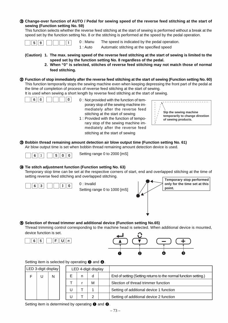
– 73 –
aaaaa Change-over function of AUTO / Pedal for sewing speed of the reverse feed stitching at the start ofsewing (Function setting No. 59)This function selects whether the reverse feed stitching at the start of sewing is performed without a break at thespeed set by the function setting No. 8 or the stitching is performed at the speed by the pedal operation.
0 : Manu The speed is indicated by the pedal operation.1 : Auto Automatic stitching at the specified speed
(Caution) 1. The max. sewing speed of the reverse feed stitching at the start of sewing is limited to thespeed set by the function setting No. 8 regardless of the pedal.
2. When “0” is selected, stitches of reverse feed stitching may not match those of normalfeed stitching.
sssss Function of stop immediately after the reverse feed stitching at the start of sewing (Function setting No. 60)This function temporarily stops the sewing machine even when keeping depressing the front part of the pedal atthe time of completion of process of reverse feed stitching at the start of sewing.It is used when sewing a short length by reverse feed stitching at the start of sewing.
0 : Not provided with the function of tem-porary stop of the sewing machine im-mediately after the reverse feedstitching at the start of sewing
1 : Provided with the function of tempo-rary stop of the sewing machine im-mediately after the reverse feedstitching at the start of sewing
ddddd Bobbin thread remaining amount detection air blow output time (Function setting No. 61)Air blow output time is set when bobbin thread remaining amount detection device is used.
Setting range 0 to 2000 [mS]
fffff Tie stitch adjustment function (Function setting No. 63)Temporary stop time can be set at the respective corners of start, end and overlapped stitching at the time ofsetting reverse feed stitching and overlapped stitching.
0 : Invalid
Setting range 0 to 1000 [mS]
ggggg Selection of thread trimmer and additional device (Function setting No.65)Thread trimming control corresponding to the machine head is selected. When additional device is mounted,device function is set.
15 9
06 0
Stp the sewing machinetemporarily to change dirextionof sewing products.
016 3
0056 1
nUF6 5
Setting item is selected by operating and .
Temporary stop performedonly for the time set at this point.
LED 3-digit display
F U N
LED 4-digit display
E n d End of setting (Setting returns to the normal function setting.)
T r M Slection of thread trimmer function
U T 1 Setting of additional device 1 function
U T 2 Setting of additional device 2 function
Setting item is determined by operating and .

– 74 –
MrTUF n
TrM : This is setting when using thread trimmer mechanism built in the machine head. Models for which thissetting is possible are as described below.
LED 3-digit display
T r. 0
LED 4-digit display Applicable model Remarks
n o P Setting invalid
L 1 5 1 Machine head of LU-151** series
L U 2 2 Machine head of LU-22** series
L 1 5 2 Machine head of LU-152* series
d 6 3 9 DLN-6390
L U 1 2 LU-2212
1TUUF n
UT1 : It is possible to set the model installed with device such as thread trimming device, cutter, etc. as theadditional device to the machine head.
LED 4-digit display Description of device setting Remarks
n o P Setting invalid
W i n d LU Thread rack device selection \A
A H 1 0 MF Auto hemmer device selection \B
S S 1 0 MF Short stitch device selection \C
T C 0 1 Tape cutter device selection (solenoid type) \D
T C 0 2 Tape cutter device selection (solenoid valve type) \E
T C 0 3 Fast action tape cutter selection \F
L B 0 1 Back latch selection \G
2TUUF n
UT2 : Same function as UT1
LED 3-digit display
U 1. 0
LED 3-digit display
U 2. 0
LED 4-digit display Description of device setting Remarks
n o P Setting invalid
W i n d LU Thread rack device selection \H
A H 1 0 MF Auto hemmer device selection \I
S S 1 0 MF Short stitch device selection \J
T C 0 1 Tape cutter device selection (solenoid type) \K
T C 0 2 Tape cutter device selection (solenoid valve type) \L
T C 0 3 Fast action tape cutter selection \M
L B 0 1 Back latch selection \N
(Caution) Contents of thread trimming function can be automatically set as well at the time of the func-tion setting. Therefore, it is not necessary to set the function normally.
Device setting
* For the detailed setting contents, refer to the another sheet (A to E) on next page.
Device setting
* For the detailed setting contents, refer to the another sheet (F to J) on next page.
Contents of selection of thread trimmer and additional device, and list of parameter setting
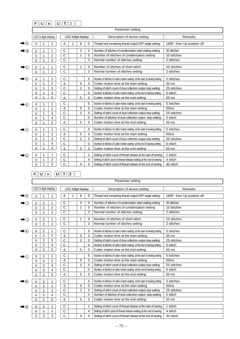
– 75 –
\A
1TUUF n
LED 3-digit display
U 1. 1
U 1. 1U 1. 2U 1. 3
U 1. 1U 1. 2
U 1. 1U 1. 2U 1. 3U 1. 4U 1. 5
U 1. 1U 1. 2U 1. 3U 1. 4U 1. 5
U 1. 1U 1. 2U 1. 3U 1. 4U 1. 5
U 1. 1U 1. 2U 1. 3
LED 4digit display Description of device setting Remarks
A. 1 8 5 Thread rack remaining thread output OFF angle setting 185fl : from Up position off
C. 3 0 Number of stitches of condensation start waiting setting 30 stitchesC. 1 0 Number of stitches of condensation setting 10 stitchesC. 2 Normal number of stitches setting 2 stitches
C. 1 0 Number of stitches of short stitch 10 stitchesC. 2 Normal number of stitches setting 2 stitches
C. 5 Number of stitches of cutter motion waiting at the start of sewing setting 5 stitchesd. 5 0 Cutter motion time at the start setting 50 msC. 2 5 Setting of stitch count of dust collection output stop waiting 25 stitches
C. 0 Number of stitches of cutter motion waiting at the end of sewing setting 0 stitch
d. 5 0 Cutter motion time at the end setting 50 ms
C. 5 Number of stitches of cutter motion waiting at the start of sewing setting 5 stitches
d. 5 0 Cutter motion time at the start setting 50msC. 2 5 Setting of stitch count of dust collection output stop waiting 25 stitchesC. 0 Number of stitches of dust collection output stop waiting 0 stitch
d. 5 0 Cutter motion time at the end setting 50 ms
C. 5 Number of stitches of cutter motion waiting at the start of sewing setting 5 stitches
d. 5 0 Cutter motion time at the start setting 50ms
C. 2 5 Setting of stitch count of dust collection output stop waiting 25 stitches
C. 0 Number of stitches of cutter motion waiting at the end of sewing setting 0 stitch
d. 5 0 Cutter motion time at the end setting 50 ms
C. 1 Setting of stitch count of thread release at the start of sewing 1 stitchC. 4 Setting of stitch count of thread release waiting at the end of sewing 4 stitchC. 4 0 Setting of stitch count of thread release at the end of sewing 40 stitch
\B
\C
\D
\E
\H
LED 3-digit display
U 2. 1
U 2. 1U 2. 2U 2. 3
U 2. 1U 2. 2
U 2. 1U 2. 2U 2. 3U 2. 4U 2. 5
U 2. 1U 2. 2U 2. 3U 2. 4U 2. 5
U 2. 1U 2. 2U 2. 3U 2. 4U 2. 5
U 2. 1U 2. 2U 2. 3
LED 4digit display Description of device setting Remarks
A. 1 8 5 Thread rack remaining thread output OFF angle setting 185fl : from Up position off
C. 3 0 Number of stitches of condensation start waiting setting 30 stitchesC. 1 0 Number of stitches of condensation setting 10 stitchesC. 2 Normal number of stitches setting 2 stitches
C. 1 0 Number of stitches of short stitch 10 stitchesC. 2 Normal number of stitches setting 2 stitches
C. 5 Number of stitches of cutter motion waiting at the start of sewing setting 5 stitchesd. 5 0 Cutter motion time at the start setting 50 msC. 2 5 Setting of stitch count of dust collection output stop waiting 25 stitchesC. 0 Number of stitches of cutter motion waiting at the end of sewing setting 0 stitchd. 5 0 Cutter motion time at the end setting 50 ms
C. 5 Number of stitches of cutter motion waiting at the start of sewing setting 5 stitches
d. 5 0 Cutter motion time at the start setting 50msC. 2 5 Setting of stitch count of dust collection output stop waiting 25 stitchesC. 0 Number of stitches of cutter motion waiting at the end of sewing setting 0 stitch
d. 5 0 Cutter motion time at the end setting 50 ms
C. 5 Number of stitches of cutter motion waiting at the start of sewing setting 5 stitchesd. 5 0 Cutter motion time at the start setting 50msC. 2 5 Setting of stitch count of dust collection output stop waiting 25 stitchesC. 0 Number of stitches of dust collection output stop waiting 0 stitch
d. 5 0 Cutter motion time at the end setting 50 ms
C. 1 Setting of stitch count of thread release at the start of sewing 1 stitch
C. 4 Setting of stitch count of thread release waiting at the end of sewing 4 stitch
C. 4 0 Setting of stitch count of thread release at the end of sewing 40 stitch
\I
\J
\K
\L
2TUUF n
\F
\G
\M
\N
Parameter setting
Parameter setting

– 76 –
1. Turn on the power. (You will view the contents shown in this illustration during operation.)
""-"" is added under A, B, C, and D indications.
2. Calling up setting mode
Press the “” switch.The screen shown in the left illustration appears and the stitchcounts (C display) in each process are displayed.(Caution) The sewing machine is disabled during these con-
tents are displayed.
3. Increase in stitch count (time)
Increase in stitch count
0-999 stitches Press the “+” switch.
The stitch count to be set increases in response to switch press-ing.
The repeat function is also available.
4. Decrease in stitch count (time)
Decrease in stitch count
Press the “-” switch.The stitch count to be set decreases in response to switch press-ing.
The repeat function is also available.
5. Progress to next step
Step forward
U1.1 → U1.2 → U1.3 Press the “” switch.
The process progresses to the next in response to switch press-
ing.
6. Determination of contents
Determination of settings Press the “” switch.
Pressing the switch provide you with determination of the changedcontents and the regular screen appears.In case that you turn off the power during setting change, theexisting settings are not updated to the changed settings.The pedal operation and other operations become enabled whenthe regular screen appears.
When MF, MO, DLN, or MH is selected for the head of the sewing machine and the additional thread trimmerfunction is selected in function setting No. 65, parameters for each additional device are changeable without startingthe memory switch function.
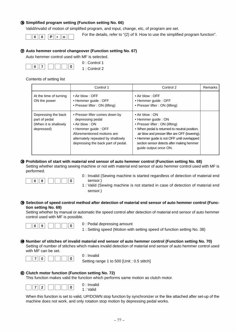
– 77 –
hhhhh Simplified program setting (Function setting No. 66)
Valid/invalid of motion of simplified program, and input, change, etc, of program are set.
For the details, refer to “(2) of 9. How to use the simplified program function”.
jjjjj Auto hemmer control changeover (Function setting No. 67)
Auto hemmer control used with MF is selected.
0 : Control 1
1 : Control 2
Contents of setting list
Control 1 Control 2 Remarks
At the time of turning • Air blow : OFF • Air blow : OFFON the power • Hemmer guide : OFF • Hemmer guide : OFF
• Presser lifter : ON (lifting) • Presser lifter : ON (lifting)
Depressing the back • Presser lifter comes down by • Air blow : ONpart of pedal depressing pedal • Hemmer guide : ON(When it is shallowly • Air blow : ON • Presser lifter : ON (lifting)depressed) • Hemmer guide : OFF • When pedal is returned to neutral position,
Aforementioned motions are air blow and presser lifter are OFF (lowering).alternately repeated by shallowly • Hemmer guide is not OFF until overlappeddepressing the back part of pedal. section sensor detects after making hemmer
guide output once ON.
kkkkk Prohibition of start with material end sensor of auto hemmer control (Function setting No. 68)Setting whether starting sewing machine or not with material end sensor of auto hemmer control used with MF isperformed.
0 : Invalid (Sewing machine is started regardless of detection of material endsensor.)
1 : Valid (Sewing machine is not started in case of detection of material endsensor.)
lllll Selection of speed control method after detection of material end sensor of auto hemmer control (Func-tion setting No. 69)Setting whether by manual or automatic the speed control after detection of material end sensor of auto hemmercontrol used with MF is possible.
0 : Pedal depressing amount1 : Setting speed (Motion with setting speed of function setting No. 38)
;;;;; Number of stitches of invalid material end sensor of auto hemmer control (Function setting No. 70)Setting of number of stitches which makes invalid detection of material end sensor of auto hemmer control usedwith MF can be set.
0 : InvalidSetting range 1 to 500 [Unit : 0.5 stitch]
zzzzz Clutch motor function (Function setting No. 72)This function makes valid the function which performs same motion as clutch motor.
0 : Invalid1 : Valid
When this function is set to valid, UP/DOWN stop function by synchronizer or the like attached after set-up of themachine does not work, and only rotation stop motion by depressing pedal works.
orP6 6
06 7
06 8
06 9
07 0
07 2
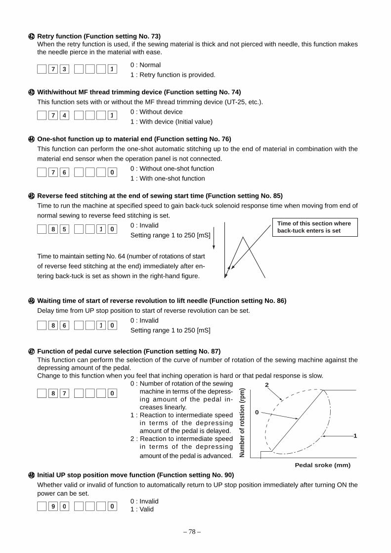
– 78 –
xxxxx Retry function (Function setting No. 73)When the retry function is used, if the sewing material is thick and not pierced with needle, this function makesthe needle pierce in the material with ease.
0 : Normal
1 : Retry function is provided.
ccccc With/without MF thread trimming device (Function setting No. 74)
This function sets with or without the MF thread trimming device (UT-25, etc.).
0 : Without device
1 : With device (Initial value)
vvvvv One-shot function up to material end (Function setting No. 76)
This function can perform the one-shot automatic stitching up to the end of material in combination with the
material end sensor when the operation panel is not connected.
0 : Without one-shot function
1 : With one-shot function
bbbbb Reverse feed stitching at the end of sewing start time (Function setting No. 85)
Time to run the machine at specified speed to gain back-tuck solenoid response time when moving from end of
normal sewing to reverse feed stitching is set.
0 : Invalid
Setting range 1 to 250 [mS]
Time to maintain setting No. 64 (number of rotations of start
of reverse feed stitching at the end) immediately after en-
tering back-tuck is set as shown in the right-hand figure.
nnnnn Waiting time of start of reverse revolution to lift needle (Function setting No. 86)
Delay time from UP stop position to start of reverse revolution can be set.
0 : Invalid
Setting range 1 to 250 [mS]
mmmmm Function of pedal curve selection (Function setting No. 87)This function can perform the selection of the curve of number of rotation of the sewing machine against thedepressing amount of the pedal.Change to this function when you feel that inching operation is hard or that pedal response is slow.
0 : Number of rotation of the sewingmachine in terms of the depress-ing amount of the pedal in-creases linearly.
1 : Reaction to intermediate speedin terms of the depressingamount of the pedal is delayed.
2 : Reaction to intermediate speedin terms of the depressingamount of the pedal is advanced.
,,,,, Initial UP stop position move function (Function setting No. 90)
Whether valid or invalid of function to automatically return to UP stop position immediately after turning ON thepower can be set.
0 : Invalid1 : Valid
Pedal sroke (mm)
Num
ber o
f rot
stio
n (r
pm) 2
0
1
17 3
07 6
08 7
018 5Time of this section where back-tuck enters is set
018 6
09 0
17 4
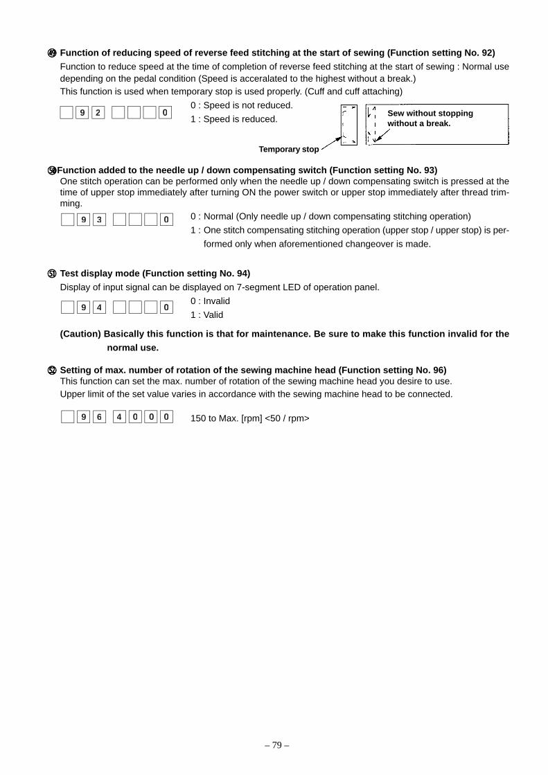
– 79 –
..... Function of reducing speed of reverse feed stitching at the start of sewing (Function setting No. 92)
Function to reduce speed at the time of completion of reverse feed stitching at the start of sewing : Normal usedepending on the pedal condition (Speed is acceralated to the highest without a break.)This function is used when temporary stop is used properly. (Cuff and cuff attaching)
0 : Speed is not reduced.
1 : Speed is reduced.
/////Function added to the needle up / down compensating switch (Function setting No. 93)One stitch operation can be performed only when the needle up / down compensating switch is pressed at thetime of upper stop immediately after turning ON the power switch or upper stop immediately after thread trim-ming.
0 : Normal (Only needle up / down compensating stitching operation)
1 : One stitch compensating stitching operation (upper stop / upper stop) is per-
formed only when aforementioned changeover is made.
¡¡¡¡¡ Test display mode (Function setting No. 94)
Display of input signal can be displayed on 7-segment LED of operation panel.
0 : Invalid
1 : Valid
(Caution) Basically this function is that for maintenance. Be sure to make this function invalid for the
normal use.
™™™™™ Setting of max. number of rotation of the sewing machine head (Function setting No. 96)This function can set the max. number of rotation of the sewing machine head you desire to use.Upper limit of the set value varies in accordance with the sewing machine head to be connected.
150 to Max. [rpm] <50 / rpm>
09 2
0009 6 4
09 3
09 4
Temporary stop
Sew without stoppingwithout a break.
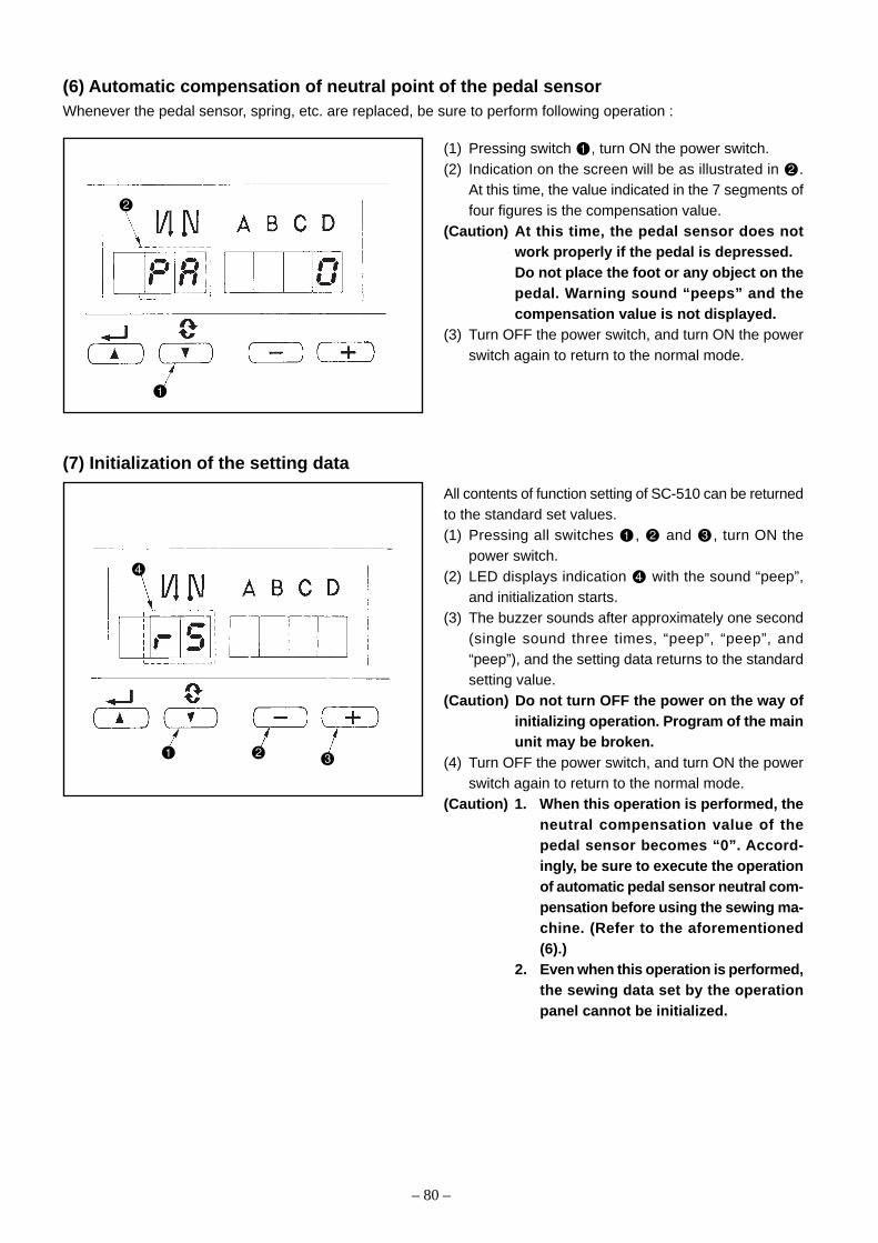
– 80 –
(7) Initialization of the setting data
All contents of function setting of SC-510 can be returnedto the standard set values.(1) Pressing all switches , and , turn ON the
power switch.(2) LED displays indication with the sound “peep”,
and initialization starts.(3) The buzzer sounds after approximately one second
(single sound three times, “peep”, “peep”, and“peep”), and the setting data returns to the standardsetting value.
(Caution) Do not turn OFF the power on the way ofinitializing operation. Program of the mainunit may be broken.
(4) Turn OFF the power switch, and turn ON the powerswitch again to return to the normal mode.
(Caution) 1. When this operation is performed, theneutral compensation value of thepedal sensor becomes “0”. Accord-ingly, be sure to execute the operationof automatic pedal sensor neutral com-pensation before using the sewing ma-chine. (Refer to the aforementioned(6).)
2. Even when this operation is performed,the sewing data set by the operationpanel cannot be initialized.
(6) Automatic compensation of neutral point of the pedal sensorWhenever the pedal sensor, spring, etc. are replaced, be sure to perform following operation :
(1) Pressing switch , turn ON the power switch.(2) Indication on the screen will be as illustrated in .
At this time, the value indicated in the 7 segments offour figures is the compensation value.
(Caution) At this time, the pedal sensor does notwork properly if the pedal is depressed.Do not place the foot or any object on thepedal. Warning sound “peeps” and thecompensation value is not displayed.
(3) Turn OFF the power switch, and turn ON the powerswitch again to return to the normal mode.
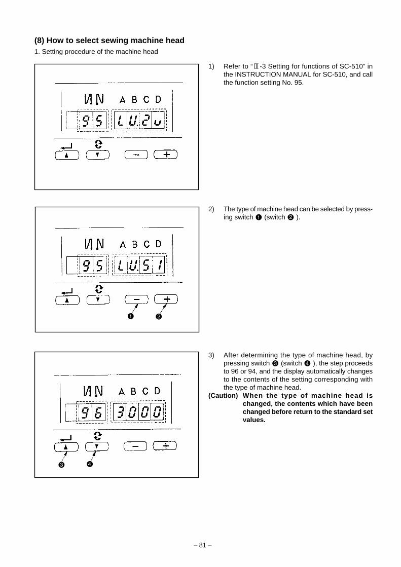
– 81 –
(8) How to select sewing machine head1. Setting procedure of the machine head
1) Refer to “3-3 Setting for functions of SC-510” inthe INSTRUCTION MANUAL for SC-510, and callthe function setting No. 95.
2) The type of machine head can be selected by press-ing switch (switch ).
3) After determining the type of machine head, bypressing switch (switch ), the step proceedsto 96 or 94, and the display automatically changesto the contents of the setting corresponding withthe type of machine head.
(Caution) When the type of machine head ischanged, the contents which have beenchanged before return to the standard setvalues.
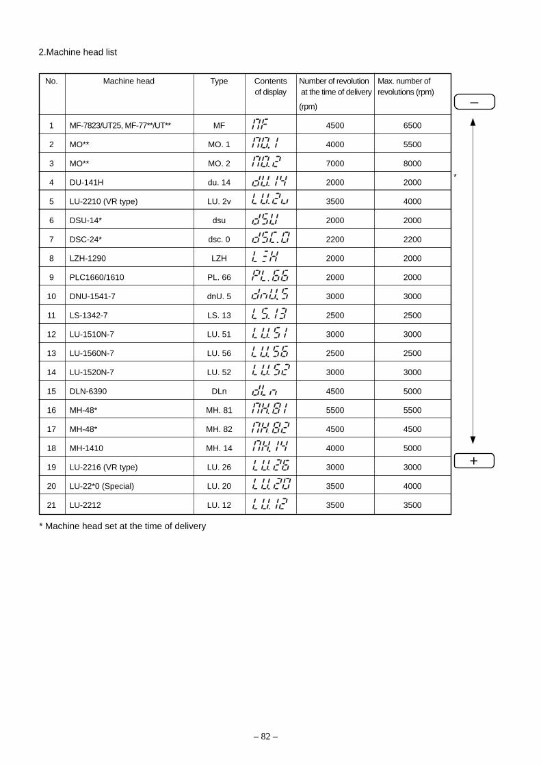
– 82 –
2.Machine head list
No. Machine head Type Contents Number of revolution Max. number ofof display at the time of delivery revolutions (rpm)
(rpm)
1 MF-7823/UT25, MF-77**/UT** MF 4500 6500
2 MO** MO. 1 4000 5500
3 MO** MO. 2 7000 8000
4 DU-141H du. 14 2000 2000
5 LU-2210 (VR type) LU. 2v 3500 4000
6 DSU-14* dsu 2000 2000
7 DSC-24* dsc. 0 2200 2200
8 LZH-1290 LZH 2000 2000
9 PLC1660/1610 PL. 66 2000 2000
10 DNU-1541-7 dnU. 5 3000 3000
11 LS-1342-7 LS. 13 2500 2500
12 LU-1510N-7 LU. 51 3000 3000
13 LU-1560N-7 LU. 56 2500 2500
14 LU-1520N-7 LU. 52 3000 3000
15 DLN-6390 DLn 4500 5000
16 MH-48* MH. 81 5500 5500
17 MH-48* MH. 82 4500 4500
18 MH-1410 MH. 14 4000 5000
19 LU-2216 (VR type) LU. 26 3000 3000
20 LU-22*0 (Special) LU. 20 3500 4000
21 LU-2212 LU. 12 3500 3500
*
–
+
* Machine head set at the time of delivery
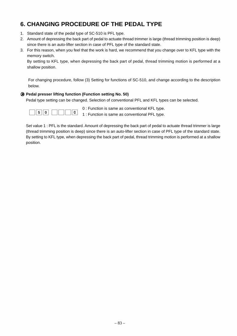
– 83 –
6. CHANGING PROCEDURE OF THE PEDAL TYPE1. Standard state of the pedal type of SC-510 is PFL type.2. Amount of depressing the back part of pedal to actuate thread trimmer is large (thread trimming position is deep)
since there is an auto-lifter section in case of PFL type of the standard state.3. For this reason, when you feel that the work is hard, we recommend that you change over to KFL type with the
memory switch.By setting to KFL type, when depressing the back part of pedal, thread trimming motion is performed at a
shallow position.
For changing procedure, follow (3) Setting for functions of SC-510, and change according to the description
below.
rrrrr Pedal presser lifting function (Function setting No. 50)
Pedal type setting can be changed. Selection of conventional PFL and KFL types can be selected.
0 : Function is same as conventional KFL type.
1 : Function is same as conventional PFL type.
Set value 1 : PFL is the standard. Amount of depressing the back part of pedal to actuate thread trimmer is large(thread trimming position is deep) since there is an auto-lifter section in case of PFL type of the standard state.By setting to KFL type, when depressing the back part of pedal, thread trimming motion is performed at a shallowposition.
05 0
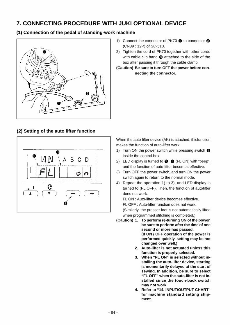
– 84 –
1) Connect the connector of PK70 to connector (CN39 : 12P) of SC-510.
2) Tighten the cord of PK70 together with other cordswith cable clip band attached to the side of thebox after passing it through the cable clamp.
(Caution) Be sure to turn OFF the power before con-necting the connector.
(1) Connection of the pedal of standing-work machine
7. CONNECTING PROCEDURE WITH JUKI OPTIONAL DEVICE
When the auto-lifter device (AK) is attached, thisfunctionmakes the function of auto-lifter work.1) Turn ON the power switch while pressing switch
inside the control box.2) LED display is turned to , (FL ON) with “beep”,
and the function of auto-lifter becomes effective.3) Turn OFF the power switch, and turn ON the power
switch again to return to the normal mode.4) Repeat the operation 1) to 3), and LED display is
turned to (FL OFF). Then, the function of autolifterdoes not work.FL ON : Auto-lifter device becomes effective.FL OFF : Auto-lifter function does not work.(Similarly, the presser foot is not automatically liftedwhen programmed stitching is completed.)
(Caution) 1. To perform re-turning ON of the power,be sure to perform after the time of onesecond or more has passed.(If ON / OFF operation of the power isperformed quickly, setting may be notchanged over well.)
2. Auto-lifter is not actuated unless thisfunction is properly selected.
3. When “FL ON” is selected without in-stalling the auto-lifter device, startingis momentarily delayed at the start ofsewing. In addition, be sure to select“FL OFF” when the auto-lifter is not in-stalled since the touch-back switchmay not work.
4. Refer to “14. INPUT/OUTPUT CHART”for machine standard setting ship-ment.
(2) Setting of the auto lifter function
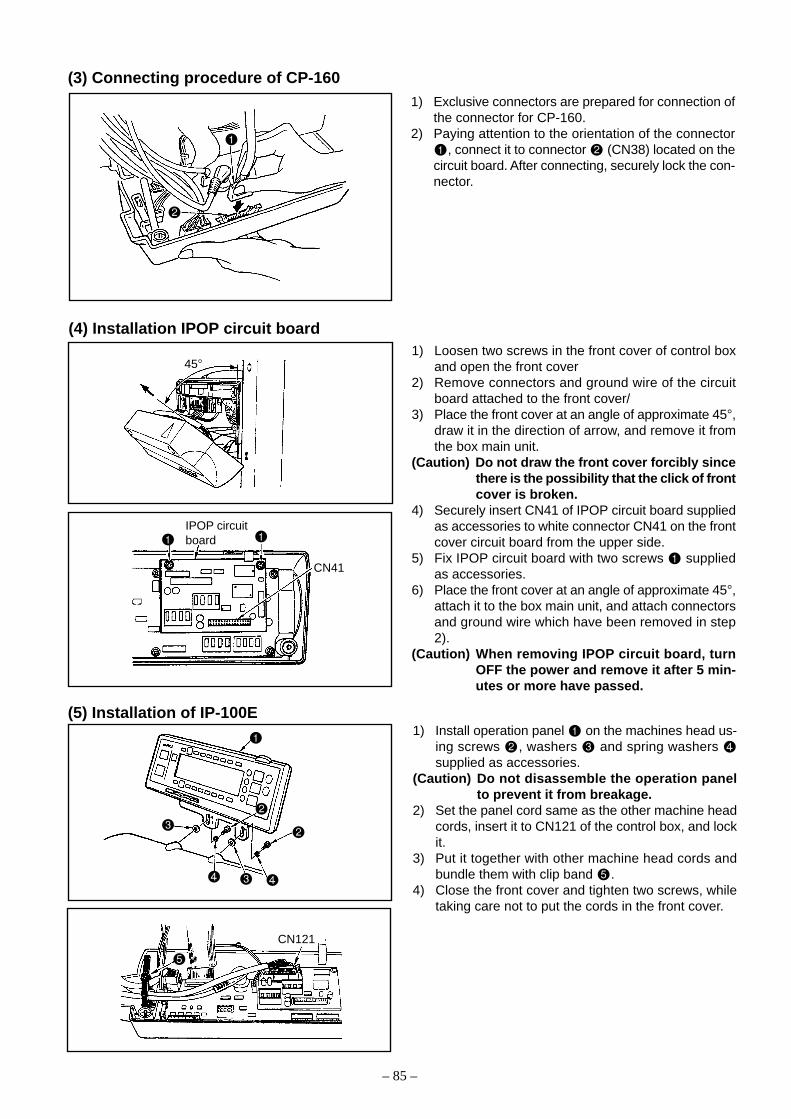
– 85 –
1) Exclusive connectors are prepared for connection ofthe connector for CP-160.
2) Paying attention to the orientation of the connector, connect it to connector (CN38) located on the
circuit board. After connecting, securely lock the con-nector.
(3) Connecting procedure of CP-160
1) Loosen two screws in the front cover of control boxand open the front cover
2) Remove connectors and ground wire of the circuitboard attached to the front cover/
3) Place the front cover at an angle of approximate 45°,draw it in the direction of arrow, and remove it fromthe box main unit.
(Caution) Do not draw the front cover forcibly sincethere is the possibility that the click of frontcover is broken.
4) Securely insert CN41 of IPOP circuit board suppliedas accessories to white connector CN41 on the frontcover circuit board from the upper side.
5) Fix IPOP circuit board with two screws suppliedas accessories.
6) Place the front cover at an angle of approximate 45°,attach it to the box main unit, and attach connectorsand ground wire which have been removed in step2).
(Caution) When removing IPOP circuit board, turnOFF the power and remove it after 5 min-utes or more have passed.
(4) Installation IPOP circuit board
(5) Installation of IP-100E1) Install operation panel on the machines head us-
ing screws , washers and spring washers supplied as accessories.
(Caution) Do not disassemble the operation panelto prevent it from breakage.
2) Set the panel cord same as the other machine headcords, insert it to CN121 of the control box, and lockit.
3) Put it together with other machine head cords andbundle them with clip band .
4) Close the front cover and tighten two screws, whiletaking care not to put the cords in the front cover.
45°
CN41
IPOP circuitboard
CN121

– 86 –
8. EXTERNAL INPUT/OUTPUT CONNECTOR(SIGNAL CONNECTOR FOR EXTENSION)
(1) Encoder output connector (CN40)
(2) Optional input/output connectors (CN50 and CN51)
Optional input/output of input 8 and output 8 can be used as standard by user’s program input. In addition, itis possible to optionally select the respective powers of +5V, +12V and +24V by changing the setting ofjumper plug.
For the details, refer to 9. HOW TO USE THE SIMPLIFIED PROGRAM FUNCTION.
CN40 pin No. Signal name Description Electric spec.
1 UDET (N) “LOW” is output when upper position angle +5V 100mA
from synchronizer is reached.
2 DDET (N) “LOW” is output when lower position angle +5V 100mA
from synchronizer is reached.
3 N. C
4 MA The A phase pulse from servo motor encoder +5V 100mA
encoder is output.
5 MB The B phase pulse from servo motor encoder +5V 100mA
is output.
(Pulse of the phase A which is delayed by 90° is output.)
6 M_ERROR “LOW” is output when the sewing machine +5V 100mA
has stopped by error.
7 +5V For electric power +5V
8 GND
[Data]
When using for connection of optional connectors, we recommend that you use the plug of format below.
Manufacturers’ name : SUMITOMO 3M
Product name : Mini-clamp wire mount plug
There are kinds as shown below according to the wires used.
Applicable wire list
(Caution) Mini clamp wire mount plug is the registered trademark of SUMITOMO 3M company.
Wire mount plug AWG No. Nominal sectional area Finished outer diameter Cover color
4-pole product No. mm SQ. ø mm
37104-3101-000FL 24-26 0.14-0.3 or less 0.8 - 1.0 Red
37104-3122-000FL 24-26 0.14-0.3 or less 1.0 - 1.2 Yellow
37104-3163-000FL 24-26 0.14-0.3 or less 1.2 - 1.6 Orange
37104-2124-000FL 20-22 0.3 or more -0.5 1.0 - 1.2 Green
37104-2165-000FL 20-22 0.3 or more -0.5 1.2 - 1.6 Blue
37104-2206-000FL 20-22 0.3 or more -0.5 1.6 - 2.0 Gray
Applicable wire
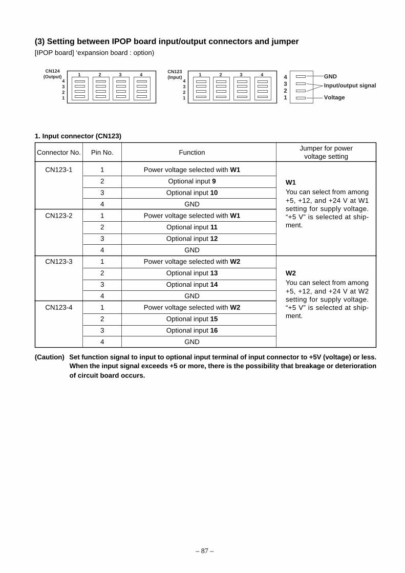
– 87 –
(3) Setting between IPOP board input/output connectors and jumper[IPOP board] ‘expansion board : option)
1. Input connector (CN123)
Connector No. Pin No. Function
CN123-1 1 Power voltage selected with W1
2 Optional input 9
3 Optional input 10
4 GND
CN123-2 1 Power voltage selected with W1
2 Optional input 11
3 Optional input 12
4 GND
CN123-3 1 Power voltage selected with W2
2 Optional input 13
3 Optional input 14
4 GND
CN123-4 1 Power voltage selected with W2
2 Optional input 15
3 Optional input 16
4 GND
Jumper for powervoltage setting
W1You can select from among+5, +12, and +24 V at W1setting for supply voltage.“+5 V” is selected at ship-ment.
W2You can select from among+5, +12, and +24 V at W2setting for supply voltage.“+5 V” is selected at ship-ment.
(Caution) Set function signal to input to optional input terminal of input connector to +5V (voltage) or less.When the input signal exceeds +5 or more, there is the possibility that breakage or deteriorationof circuit board occurs.
1 2 3 4CN124
(Output)4321
1 2 3 4CN123(Input)
4321
4321
GND
Input/output signal
Voltage

– 88 –
2. Output connector (CN124)
Connector No. Pin No. Function
CN124-1 1 Power voltage selected with W3
2 Optional output 9
3 Optional output 10
4 GND
CN124-2 1 Power voltage selected with W3
2 Optional output 11
3 Optional output 12
4 GND
CN124-3 1 Power voltage selected with W4
2 Optional output 13
3 Optional output 14
4 GND
CN124-4 1 Power voltage selected with W4
2 Optional output 15
3 Optional output 16
4 GND
Jumper for powervoltage setting
W3You can select from among+5, +12, and +24 V at W3setting for supply voltage.“+5 V” is selected at ship-ment.
W4You can select from among+5, +12, and +24 V at W4setting for supply voltage.“+5 V” is selected at ship-ment.
(Caution) Do not apply voltage exceeding the value set with W3 and W4 (jumpers for power voltage) to theoptional output terminal of output connector. When voltage exceeding the setting is applied,there is the possibility that breakage or deterioration of circuit board occurs. So, be careful.

– 89 –
3. Jumper arrangement for switching optional power supply
W4 W1 W2
W3 W4
W1
W3
CN124
CN123
5V 12V 24V
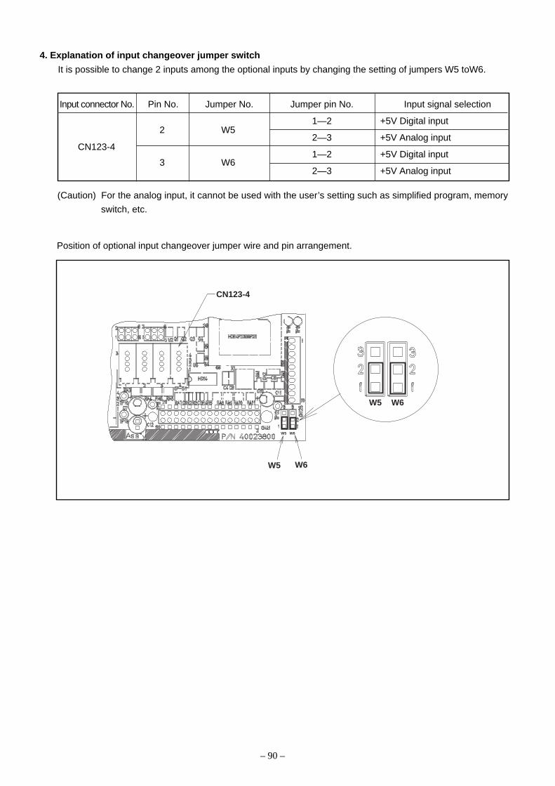
– 90 –
4. Explanation of input changeover jumper switch
It is possible to change 2 inputs among the optional inputs by changing the setting of jumpers W5 toW6.
Input connector No. Pin No. Jumper No. Jumper pin No. Input signal selection
1—2 +5V Digital input
2—3 +5V Analog input
1—2 +5V Digital input
2—3 +5V Analog input
CN123-4
2 W5
3 W6
(Caution) For the analog input, it cannot be used with the user’s setting such as simplified program, memory
switch, etc.
Position of optional input changeover jumper wire and pin arrangement.
CN123-4
W5 W6
W5 W6
W5 W6

– 91 –
(4) How to crimp the optional connector
1. Cable insertion(1) After checking the pin number, insert the cable
into the inlet between the top cover and base cover
.
(2) Observe the cable coming to the hole end (to theline in the illustration) from above of the top cover
.
2. Crimp
Crimp the cover and the body together with pli-ers .* Pliers should be lateral to the cable direction as
shown in the illustration.
Inlet
Hole end
Hole end
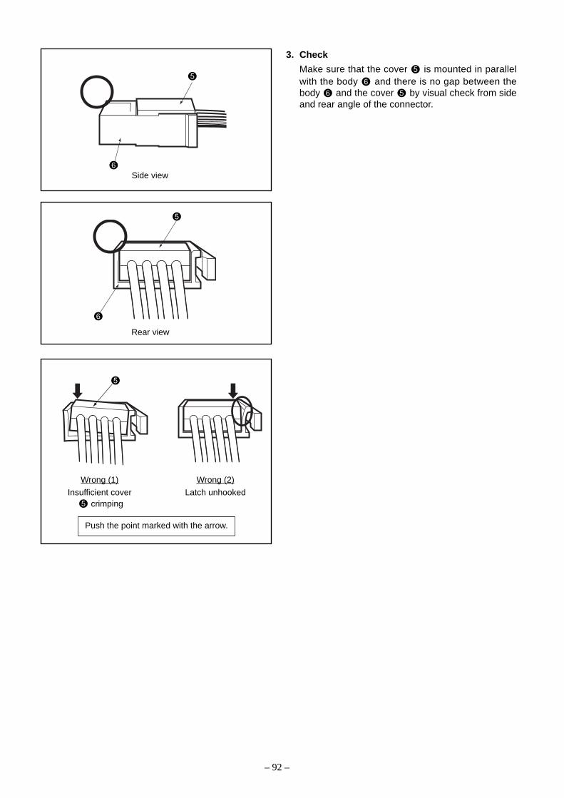
– 92 –
3. Check
Make sure that the cover is mounted in parallelwith the body and there is no gap between thebody and the cover by visual check from sideand rear angle of the connector.
Wrong (1)
Insufficient cover crimping
Wrong (2)
Latch unhooked
Push the point marked with the arrow.
Side view
Rear view

– 93 –
IndicationPro__EndPro1Pro2Pro3Pro4
FunctionIndicates program selection mode.Ends program input function.Selects program 1.Selects program 2.Selects program 3.Selects program 4.
Remarks
Indication66
Pro
FunctionSetting function No.Indication of program input mode.
Remarks
Indication_oFF_onCHE_Pro_
FunctionStops program operation.Makes valid program operation.Can confirm contents of program.Starts input mode of program.
RemarksPossible to select only when 3-digit LED indication is *.0
Possible to select only when 3-digit LED indication is *.0
Possible to select only when 3-digit LED indication is *.0
Possible to select only when 3-digit LED indication is *.0
Indication0
1 to 20
FunctionOperation mode selectionProgram step No.
RemarksRefer to the aforementioned list.
Indication1234
FunctionInputting program 1.Inputting program 2.Inputting program 3.Inputting program 4.
Remarks
9. HOW TO USE THE SIMPLIFIED PROGRAM FUNCTION(1) Simplified program function
SC-510 does not use the exclusive input device or the like and has the function that can create the simplified
programs which take in the signals from the outside, output the signals to the outside, and control the sewing
machine head by SC-510 main unit only.
1. Specifications
1) It is possible to simultaneously perform the operation of four programs.
2) It is possible to input 20 steps per program.
3) It is possible to perform the cross operation among four programs.
2. Indication and function
1) Indication when the simplified program is selected
2) Indication when the program is selected

– 94 –
Turn OFF the power and re-turn ON the power,and program inputted to "Pro1" starts operation.
With key, program slips out of input mode to end input.
When "on" indication appears, operation of program 1 is possible.
Press + or - key to select program No.
This case is when program No. 1 is selected.
Press or key to move to program input mode.
Press + or - key to select program input.
Press key to move to program input mode.
With key, program slips out of input mode.
Program input(Command input)
End ofprogram input
Press + or - key to select command to be inputted.(For command input, refer to (3). Command input and (4). Simplifiedprogram command list.)
Press + or - key to select "End" command.By selecting this command, program input can be ended.
Program cannot be operated in this indication,Move to "on" indication with "+" or "-" key.
(2) Sequence of start and inputStart the setting mode and select function No. 66 in accordance with “Setting for functions of SC-510”.
When No. 66 is selected, indication below appears.
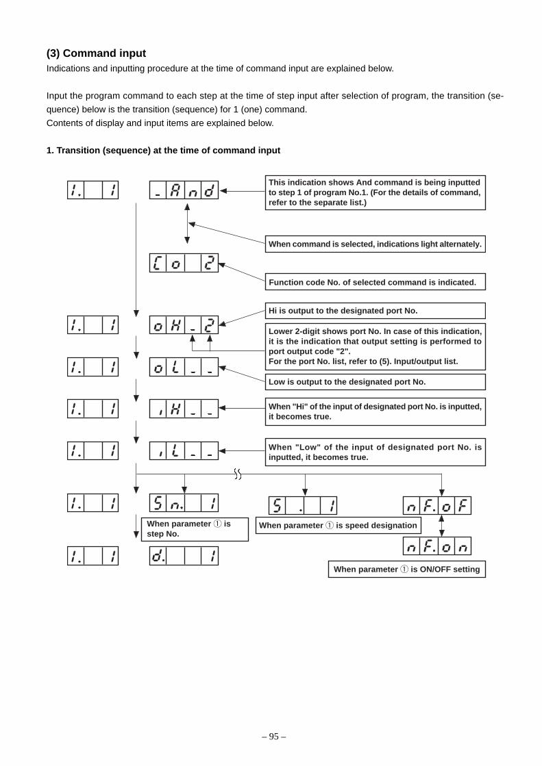
– 95 –
This indication shows And command is being inputtedto step 1 of program No.1. (For the details of command,refer to the separate list.)
When command is selected, indications light alternately.
Function code No. of selected command is indicated.
Lower 2-digit shows port No. In case of this indication,it is the indication that output setting is performed toport output code "2".For the port No. list, refer to (5). Input/output list.
Low is output to the designated port No.
When "Hi" of the input of designated port No. is inputted,it becomes true.
When "Low" of the input of designated port No. isinputted, it becomes true.
When parameter 1 isstep No.
When parameter 1 is ON/OFF setting
When parameter 1 is speed designation
Hi is output to the designated port No.
(3) Command inputIndications and inputting procedure at the time of command input are explained below.
Input the program command to each step at the time of step input after selection of program, the transition (se-
quence) below is the transition (sequence) for 1 (one) command.
Contents of display and input items are explained below.
1. Transition (sequence) at the time of command input

– 96 –
MEMO
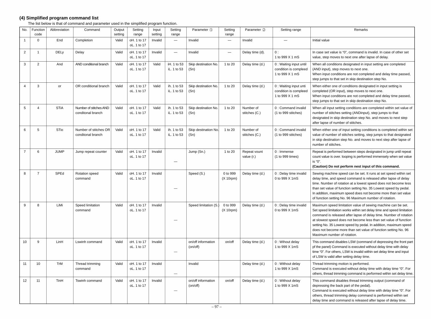
– 97 –
(4) Simplified program command listThe list below is that of command and parameter used in the simplified program function.
No. Function Abbreviation Command Output Setting Input Setting Parameter 1 Setting Parameter 2 Setting range Remarkscode setting range setting range range
1 0 End Completion Valid oH. 1 to 17 Invalid — Invalid — Invalid — Initial value
oL. 1 to 17
2 1 DELy Delay Valid oH. 1 to 17 Invalid — Invalid — Delay time (d). 0 : In case set value is “0”, command is invalid. In case of other setoL. 1 to 17 1 to 999 X 1 mS value, step moves to next one after lapse of delay.
3 2 And AND conditional branch Valid oH. 1 to 17 Valid iH. 1 to 53 Skip destination No. 1 to 20 Delay time (d.) 0 : Waiting input until When all conditions designated in input setting are completed
oL. 1 to 17 iL. 1 to 53 (Sn) condition is compleed (AND input), step moves to next one.1 to 999 X 1 mS When input conditions are not completed and delay time passed,
step jumps to that set in skip destination step No.
4 3 or OR conditional branch Valid oH. 1 to 17 Valid ih. 1 to 53 Skip destination No. 1 to 20 Delay time (d.) 0 : Waiting input unti When either one of conditions designated in input setting is
oL. 1 to 17 iL. 1 to 53 (Sn) condition is compleed completed (OR input), step moves to next one.1 to 999 X 1 mS When input conditions are not completed and delay time passed,
step jumps to that set in skip destination step No.
5 4 STiA Number of stitches AND Valid oH. 1 to 17 Valid ih. 1 to 53 Skip destination No. 1 to 20 Number of 0 : Command invalid When all input setting conditions are completed within set value ofconditonal branch oL. 1 to 17 iL. 1 to 53 (Sn) stitches (C.) (1 to 999 stitches) number of stitches setting (ANDinput), step jumps to that
designated in skip destination step No. and moves to next step
after lapse of number of stitches.
6 5 STio Number of stitches OR Valid oH. 1 to 17 Valid ih. 1 to 53 Skip destination No. 1 to 20 Number of 0 : Command invalid When either one of input setting conditions is completed within setconditonal branch oL. 1 to 17 iL. 1 to 53 (Sn) stitches (C.) (1 to 999 stitches) value of number of stitches setting, step jumps to that designated
in skip destination step No. and moves to next step after lapse of
number of stitches.
7 6 JUMP Jump repeat counter Valid oH. 1 to 17 Invalid Jump (Sn.) 1 to 20 Repeat vount 0 : Immense Repeat is performed between steps designated in jump until repeat
oL. 1 to 17 value (r.) (1 to 999 times) count value is over. looping is performed immensely when set value
— is “0”.(Caution) Do not perform nest input of this command.
8 7 SPEd Rotation speed Valid oH. 1 to 17 Invalid Speed (S.) 0 to 999 Delay time (d.) 0 : Delay time invalid Sewing machine speed can be set. It runs at set speed within set
command oL. 1 to 17 (X 10rpm) 0 to 999 X 1mS delay time, and speed command is released after lapse of delaytime. Number of rotation at a lowest speed does not become less
— than set value of function setting No. 35 Lowest speed by pedal.
In addition, maximum speed does not become more than set valueof function setting No. 96 Maximum number of rotation.
9 8 LiMi Speed limitation Valid oH. 1 to 17 Invalid Speed limitation (S.) 0 to 999 Delay time (d.) 0 : Delay time invalid Maximum speed limitation value of sewing machine can be set.
command oL. 1 to 17 (X 10rpm) 0 to 999 X 1mS Set speed limitation works within set delay time and speed limitation
command is released after lapse of delay time. Number of rotation— at slowest speed does not become less than set value of function
setting No. 35 Lowest speed by pedal. In addition, maximum speed
does not become more than set value of function setting No. 96Maximum number of rotation.
10 9 LinH Lswinh command Valid oH. 1 to 17 Invalid on/off information on/off Delay time (d.) 0 : Wihout delay This command disables LSW (command of depressing the front part
oL. 1 to 17 (on/off) 1 to 999 X 1mS pf the panel) Command is executed without delay time with delay— time “0”. For others, LSW is invalid within set delay time and input
of LSW is valid after setting delay time.
11 10 TrM Thread trimming Valid oH. 1 to 17 Invalid Invalid Delay time (d.) 0 : Without delay Thread trimming motion is performed.
command oL. 1 to 17 1 to 999 X 1mS Command is executed without delay time with delay time “0”. For— others, thread trimming command is performed within set delay time.
12 11 TinH Tswinh command Valid oH. 1 to 17 Invalid on/off information on/off Delay time (d.) 0 : Without delay This command disables thread trimming output (command of
oL. 1 to 17 (on/off) 1 to 999 X 1mS depressing the back part of the pedal).— Command is executed without delay time with delay time “0”. For
others, thread trimming delay command is performed within set
delay time and command is released after lapse of delay time.

– 98 –
No. Function Abbreviation Command Output Setting Input Setting Parameter 1 Setting Parameter 2 Setting range Remarkscode setting range setting range range
13 12 Up US stop command Valid oH. 1 to 17 Invalid Invalid Delay time (d.) 0 : Without delay UP position stop command (speed designated with other commandoL. 1 to 17 1 to 999 X 1mS is neglected.)
— — Command is executed without delay time with delay time “0”. For
others, UP position stop command is valid within set delay timeand command is invalid after lapse of delay time.
14 13 HS Needle up/down Valid oH. 1 to 17 Invalid Invalid Delay time (d). 0 : Without delay When command is executed, sewing machine rotates normally,
command oL. 1 to 17 1 to 999 X 1 mS and needle goes to UP position when it is in DOWN position andvice versa. Even if there is speed limitation with other command, it
— — is neglected.
Command is executed without delay time with delay time “0”. Forothers, command is valid within set delay time and command is
invalid after lapse of delay time.
15 14 rSW Rsw command Valid oH. 1 to 17 Invalid Invalid Delay time (d.) 0 : Without delay When reverse rotation command is executed, sewing machine
oL. 1 to 17 1 to 999 X 1 mS brakes by reverse rotation from angle set in function setting No.— — 19 and stops. Command is executed without delay time with delay
time “0”. For others, command is valid within set delay time and
command is invalid after lapse of delay time.
16 15 AnGA Angle AND conditional Valid oH. 1 to 17 Valid iH. 1 to 53 Skip destination step No. 1 to 20 Angle (A.) 0 : Without delay Step moves to next one after lapse of set angle, and when all input
branch oL. 1 to 17 iL. 1 to 53 (Sn) 1 to 359° conditions are completed (AND input), step moves to skip
destination step No. (Angle reference is angle from UP positionmiss.)
17 16 AnGo Angle OR conditional Valid oH. 1 to 17 Valid iH. 1 to 53 Skip destination step No. 1 to 20 Angle (A.) 0 : Without delay Step moves to next one after lapse of set angle, and when either
branch oL. 1 to 17 iL. 1 to 53 (Sn) 1 to 359° one of input conditions is completed (OR input), step moves to
skip destination step No. (Angle reference is angle from UP positionmiss.)
18 17 SToP Stop command Valid oH. 1 to 17 Invalid — Invalid — Delay time (d.) 0 : Without delay Stop command is output and step moves to next one. When time
oL. 1 to 17 1 to 999 X 1 mS is set, step moves to next one after lapse of set time.
19 18 bT BTsw command Valid oH. 1 to 17 Invalid on/off information on/off Delay time (d.) 0 : Without delay On/off of reverse feed stitching switch is set.
(Reverse feed stitching oL. 1 to 17 (on/off) 1 to 999 X 1 mS Command is executed without delay time with delay time “0”. For
output) — other set value, command is executed after lapse of back-tackoutput “on” time during set time.
20 19 FL FLsw command Valid oH. 1 to 17 Invalid on/off information on/off Delay time (d.) 0 : Invalid On/off of presser lifting switch command is set.
(Presser lifting output) oL. 1 to 17 (on/off) 1 to 999 X 1 mS Command is executed without delay time with delay time “0”. For
— other set value, presser lifting output “off” is executed after lapseof presser lifting output “on” time during set time.
21 20 rEST Program reset Valid oH. 1 to 17 Invalid — Program No. (Sn) 1 to 4 Invalid — Initialization of step of designated program No. Step of designated
oL. 1 to 17 program is compulsorily returned to the first step.

– 99 –
(5) Simplified program information input setting code list and connector location listList below is the list of port input code indicated in 7-segment LED at the time of input, connector No. and pin No.on p.c.b., pin assignment, function, etc.
Input listPort input Signal name Function Connector No. Pin No. Remarks
code and pin No.on p.c.b.
0 Invalid Input is made invalid.1 opi0 Optional input-1 CN51-1 22 opi1 Optional input-2 CN51-1 33 opi2 Optional input-3 CN51-2 24 opi3 Optional input-4 CN51-2 35 opi4 Optional input-5 CN51-3 26 opi5 Optional input-6 CN51-3 37 opi6 Optional input-7 CN51-4 28 opi7 Optional input-8 CN51-4 39 opo0 Input of optional output-1 — — Output signal of optional output-1 can be internally inputted.10 opo1 Input of optional output-2 — — Output signal of optional output-2 can be internally inputted.11 opo2 Input of optional output-3 — — Output signal of optional output-3 can be internally inputted.12 opo3 Input of optional output-4 — — Output signal of optional output-4 can be internally inputted.13 opo4 Input of optional output-5 — — Output signal of optional output-5 can be internally inputted.14 opo5 Input of optional output-6 — — Output signal of optional output-6 can be internally inputted.15 opo6 Input of optional output-7 — — Output signal of optional output-7 can be internally inputted.16 opo7 Input of optional output-8 — — Output signal of optional output-8 can be internally inputted.17 TRMD Thread trimmer output CN36 118 WPD Wiper output CN36 219 TLSUBD Tension release output CN36 720 BRD Reverse feed stitching output CN36 621 FLD Presser lifting output CN37 122 BZ Buzzer output — —23 M_ERR Machine error output CN40 624 S.STATE Stop state output — —25 HSTSW Needle up/down compe- CN38 13 CP-160 (operation panel)
nsating switch input26 LSSW Low speed switch input CN39 11 Standing work type27 BTSW Reverse feed stitching CN36 5
switch input28 UDET UP position input CN33 629 DDET DOWN position input CN33 130 UP UP key input Operation panel — Front cover31 DOWN DOWN key input Operation panel — Front cover32 SET+ SET +key input Operation panel — Front cover33 SET– SET -key input Operation panel — Front cover34 TSW Thread trimmer switch input CN39 7 Standing work type35 FLSW Presser lifter switch input CN36 436 FLSW Presser lifter switch input CN39 5 Standing work type37 HSSW High speed switch input CN39 9 Standing work type38 opi8 Optional input-9 CN123-1 2 Extension p.c.b. (IPOP p.c.b.) CN12339 opi9 Optional input-10 CN123-1 3 Extension p.c.b. (IPOP p.c.b.) CN12340 opi10 Optional input-11 CN123-2 2 Extension p.c.b. (IPOP p.c.b.) CN12341 opi11 Optional input-12 CN123-2 3 Extension p.c.b. (IPOP p.c.b.) CN12342 opi12 Optional input-13 CN123-3 2 Extension p.c.b. (IPOP p.c.b.) CN12343 opi13 Optional input-14 CN123-3 3 Extension p.c.b. (IPOP p.c.b.) CN12344 opi14 Optional input-15 CN123-4 2 Extension p.c.b. (IPOP p.c.b.) CN12345 opi15 Optional input-16 CN123-4 3 Extension p.c.b. (IPOP p.c.b.) CN12346 opo8 Input of optional output-9 — — Output signal of optional output-9 can be internally inputted.47 opo9 Input of optional output-10 — — Output signal of optional output-10 can be internally inputted.48 opo10 Input of optional output-11 — — Output signal of optional output-11 can be internally inputted.49 opo11 Input of optional output-12 — — Output signal of optional output-12 can be internally inputted.50 opo12 Input of optional output-13 — — Output signal of optional output-13 can be internally inputted.51 opo13 Input of optional output-14 — — Output signal of optional output-14 can be internally inputted.52 opo14 Input of optional output-15 — — Output signal of optional output-15 can be internally inputted.53 opo15 Input of optional output-16 — — Output signal of optional output-16 can be internally inputted.
(Caution) 1. Port input codes 38 to 45 can be used only when IPOP p.c.b. is mounted.2. Operation of port input codes 9 to 16, and 46 to 53 is the function that can use as the signal in
the program where output can be internally used as input signal when optional output writtenin the function is used.
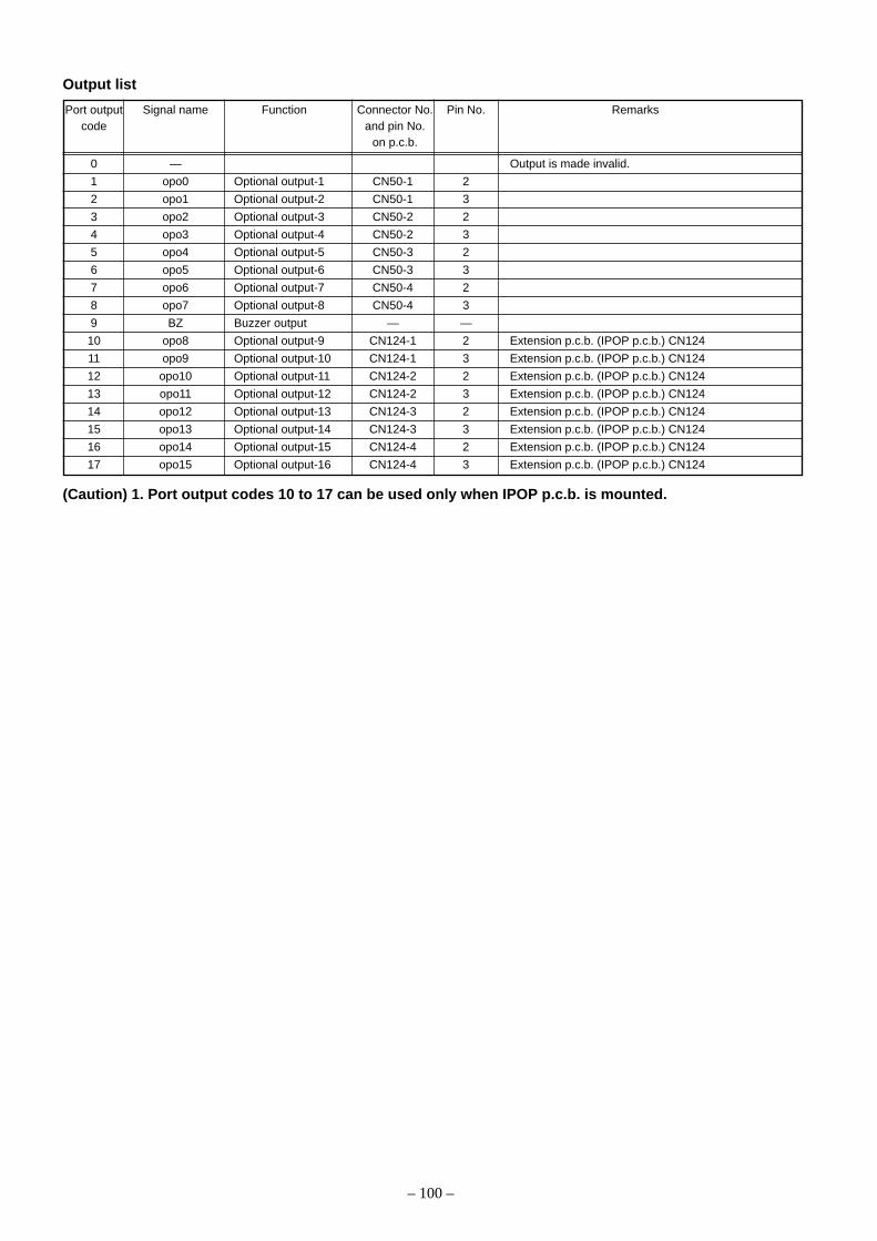
– 100 –
Output list
Port output Signal name Function Connector No. Pin No. Remarkscode and pin No.
on p.c.b.
0 — Output is made invalid.
1 opo0 Optional output-1 CN50-1 2
2 opo1 Optional output-2 CN50-1 3
3 opo2 Optional output-3 CN50-2 2
4 opo3 Optional output-4 CN50-2 3
5 opo4 Optional output-5 CN50-3 2
6 opo5 Optional output-6 CN50-3 3
7 opo6 Optional output-7 CN50-4 2
8 opo7 Optional output-8 CN50-4 3
9 BZ Buzzer output — —
10 opo8 Optional output-9 CN124-1 2 Extension p.c.b. (IPOP p.c.b.) CN124
11 opo9 Optional output-10 CN124-1 3 Extension p.c.b. (IPOP p.c.b.) CN124
12 opo10 Optional output-11 CN124-2 2 Extension p.c.b. (IPOP p.c.b.) CN124
13 opo11 Optional output-12 CN124-2 3 Extension p.c.b. (IPOP p.c.b.) CN124
14 opo12 Optional output-13 CN124-3 2 Extension p.c.b. (IPOP p.c.b.) CN124
15 opo13 Optional output-14 CN124-3 3 Extension p.c.b. (IPOP p.c.b.) CN124
16 opo14 Optional output-15 CN124-4 2 Extension p.c.b. (IPOP p.c.b.) CN124
17 opo15 Optional output-16 CN124-4 3 Extension p.c.b. (IPOP p.c.b.) CN124
(Caution) 1. Port output codes 10 to 17 can be used only when IPOP p.c.b. is mounted.

– 101 –
(6) Setting procedure of optional power and setting procedure of jumper for inputchangeover
Lists below are those of setting procedure of power voltage of optional connectors.
By setting respective jumper wires, +5V, +12V and +24V can be used.
* +5V has been set at the time of delivery from factory.
1. Input connector
2. Output connector
Caution when using optional power
1) Note that the power for optional is 0.6A in total when IPOP p.c.b. is not used, and that the power for
optional should not exceed 0.4A when IPOP p.c.b. is mounted.
3. Layout diagram of jumper for optional changeover of power
Connector No. Pin No. Setting voltage Function Jumper for optional power selection
+5V +12V +24V
CN51-1 1 Vcc4 Power voltage selected with W4 W4 1-2 W4 3-4 W4 5-6
4 — GND
CN51-2 1 Vcc4 Power voltage selected with W4
4 — GND
CN51-3 1 Vcc3 Power voltage selected with W3 W3 1-2 W3 3-4 W3 5-6
4 — GND
CN51-4 1 Vcc3 Power voltage selected with W3
4 — GND
Connector No. Pin No. Setting voltage Function Jumper for optional power selection
+5V +12V +24V
CN50-1 1 Vcc1 Power voltage selected with W1 W1 1-2 W1 3-4 W1 5-6
4 — GND
CN50-2 1 Vcc1 Power voltage selected with W1
4 — GND
CN50-3 1 Vcc2 Power voltage selected with W2 W2 1-2 W2 3-4 W2 5-6
4 — GND
CN50-4 1 Vcc2 Power voltage selected with W2
4 — GND

– 102 –
1 2 3
1 2 3Pin No.
Pin No.
Explanation of input changeover jumper switch
It is possible to change 4 inputs among the optional inputs by changing the setting of jumpers W5 to W8.
Jumper No. Pin No. Signal Input connector Remarks
W5 1-2 Digital input of +5V CN51-4 3Pin
2-3 Analog input of +5V (1) CN51-4 3Pin This input becomes analog signal input. (Caution 1.)
W6 1-2 Digital input of +5V CN51-4 2Pin
2-3 Analog input of +5V (2) CN51-4 2Pin This input becomes analog signal input. (Caution 1.)
W7 1-2 Digital input of +5V CN51-3 2Pin
2-3 Digital input of +5V CN36 3Pin
W8 1-2 Digital input of +5V CN36 3Pin
2-3 Digital input of +5V CN42 2Pin
(Caution) 1. For the analog input, it cannot be used with the user’s setting such as simplified program,memory switch, etc.
Position of optional input changeover jumper wire and pin arrangement

– 103 –
Signal system pin assignment of optional input/output connectorsList below is the list showing the relation between connector for optional and port input/output code.Be sure to keep the items of caution for use.4. Input connector
This optional input can be connected to transistor output of PLC, relay output, open collector output, push buttonswitch, etc.
(Caution) 1. Note that the input voltage should not exceed +5V.2. “+5 V” is selected at shipment.
Connector No. Pin No. Port input code Function
1 — Power voltage selected with W4
CN51-1 2 1 Optional input 1
3 2 Optional input 2
4 — GND
1 — Power voltage selected with W4
CN51-2 2 3 Optional input 3
3 4 Optional input 4
4 — GND
1 — Power voltage selected with W3
CN51-3 2 5 Optional input 5
3 6 Optional input 6
4 — GND
1 — Power voltage selected with W3
CN51-4 2 7 Optional input 7
3 8 Optional input 8
4 — GND
5. Output connectorThis optional output can be connected to solenoid valves of +5V, +12V and +24V, output to PLC, LED fordisplay, etc.
(Caution) 1. Set the current which can be driven to 0.4A per circuit or less.2. In case of driving with external power, use the power voltage which does not exceed the voltage set
with W1 or W2.3. With this output circuit, actuator of large counter electromotive force such as magnet cannot be
driven.4. When using actuator such as magnet and the like, use output of CN36.5. “+5 V” is selected at shipment.
Connector No. Pin No. Port input code Function
1 — Power voltage selected with W1
CN50-1 2 1 Optional output 1
3 2 Optional output 2
4 — GND
1 — Power voltage selected with W1
CN50-2 2 3 Optional output 3
3 4 Optional output 4
4 — GND
1 — Power voltage selected with W2
CN50-3 2 5 Optional output 5
3 6 Optional output 6
4 — GND
1 — Power voltage selected with W2
CN50-4 2 7 Optional output 7
3 8 Optional output 8
4 — GND
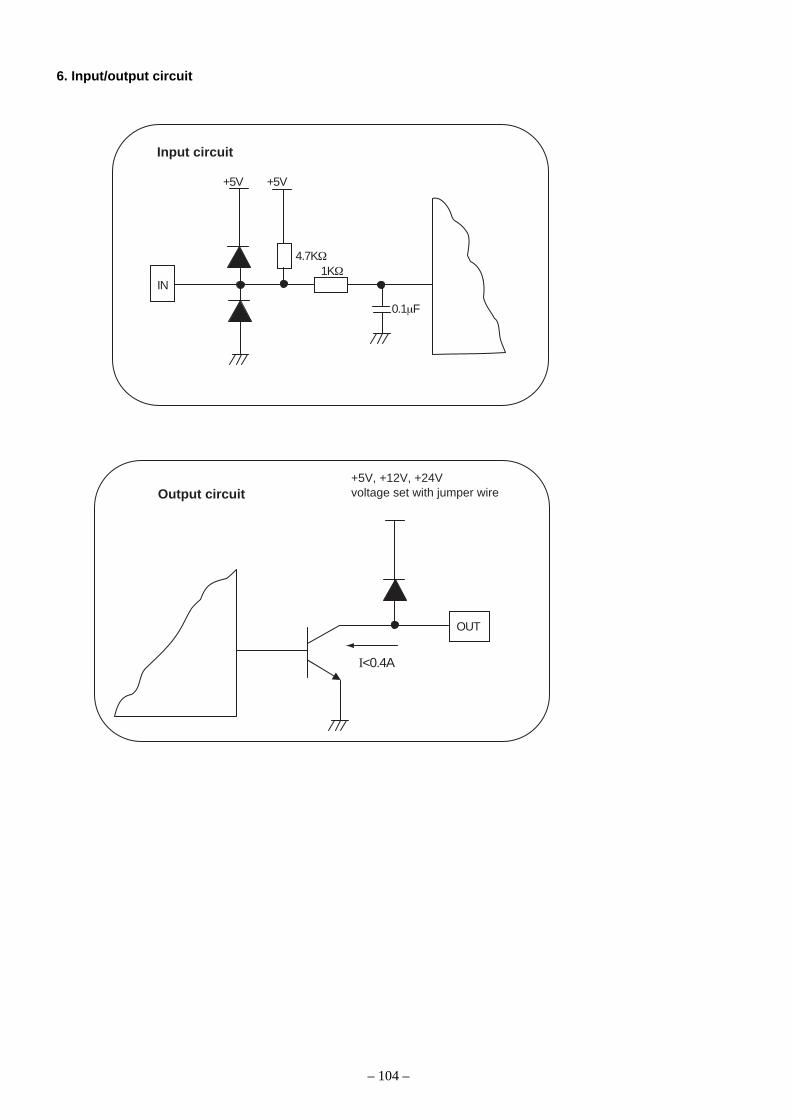
– 104 –
6. Input/output circuit
Input circuit
Output circuit
+5V
+5V, +12V, +24Vvoltage set with jumper wire
+5V
4.7KΩ
IN1KΩ
0.1µF
OUT
I<0.4A

– 105 –
6 6 P r o _
P r o _
P r o
C H E _
E n d _
_ E n d
_ E n d
_ A n d
_ _ o r
_ o F F
_ _ o n
∗.
∗.
∗.
0
1
E n d _2
P r o 1 1 1
1
3
3
2
2
2
1
1
1
P r o 2
D E L y
S T i A
S T i o
J U M P
S P E d
L i M i
L i n H
_ T r M
_ r S W
_ _ U P
_ _ H S
_ _ b T
_ _ F L
T i n H
A n G A
A n G o
S T o P
r E S T
P r o 3
P r o 4
For the details of respective commands, referto (3). Command input and (4). Simplifiedprogram command list.
Confirmation mode of input program(Programmed contents cannot be edited.)
key after selection of End command key
key afterselection of Endcommand key
Transition with +/- key
Transition with + key
key
key
key key
Transitionwith - key
Transitionwith + key
Transitionwith + key
Transitionwith + key
Transitionwith - key
(7) Transition (sequence) diagram of No. 66 simplified program functionTransition (sequence) of respective input modes is as shown below.
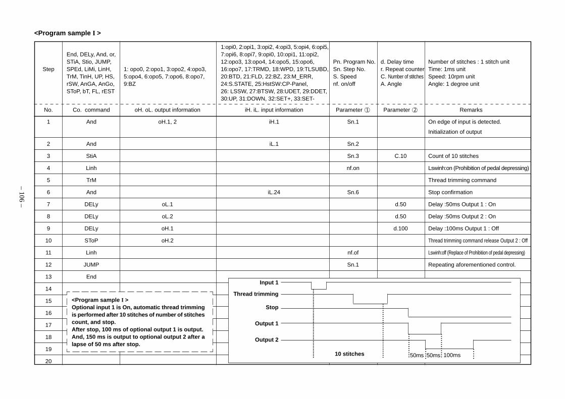
– 106 –
1 And oH.1, 2 iH.1 Sn.1 On edge of input is detected.
Initialization of output
2 And iL.1 Sn.2
3 StiA Sn.3 C.10 Count of 10 stitches
4 Linh nf.on Lswinh:on (Prohibition of pedal depressing)
5 TrM Thread trimming command
6 And iL.24 Sn.6 Stop confirmation
7 DELy oL.1 d.50 Delay :50ms Output 1 : On
8 DELy oL.2 d.50 Delay :50ms Output 2 : On
9 DELy oH.1 d.100 Delay :100ms Output 1 : Off
10 SToP oH.2 Thread trimming command release Output 2 : Off
11 Linh nf.of Lswinh:off (Replace of Prohibition of pedal depressing)
12 JUMP Sn.1 Repeating aforementioned control.
13 End
14
15
16
17
18
19
20
<Program sample I >
1:opi0, 2:opi1, 3:opi2, 4:opi3, 5:opi4, 6:opi5,End, DELy, And, or, 7:opi6, 8:opi7, 9:opi0, 10:opi1, 11:opi2,STiA, Stio, JUMP, 12:opo3, 13:opo4, 14:opo5, 15:opo6, Pn. Program No. d. Delay time Number of stitches : 1 stitch unit
Step SPEd, LiMi, LinH, 1: opo0, 2:opo1, 3:opo2, 4:opo3, 16:opo7, 17:TRMD, 18:WPD, 19:TLSUBD, Sn. Step No. r. Repeat counter Time: 1ms unitTrM, TinH, UP, HS, 5:opo4, 6:opo5, 7:opo6, 8:opo7, 20:BTD, 21:FLD, 22:BZ, 23:M_ERR, S. Speed C. Number of stitches Speed: 10rpm unitrSW, AnGA, AnGo, 9:BZ 24:S.STATE, 25:HstSW:CP-Panel, nf. on/off A. Angle Angle: 1 degree unitSToP, bT, FL, rEST 26: LSSW, 27:BTSW, 28:UDET, 29:DDET,
30:UP, 31:DOWN, 32:SET+, 33:SET-
No. Co. command oH. oL. output information iH. iL. input information Parameter 1 Parameter 2 Remarks
<Program sample I >Optional input 1 is On, automatic thread trimmingis performed after 10 stitches of number of stitchescount, and stop.After stop, 100 ms of optional output 1 is output.And, 150 ms is output to optional output 2 after alapse of 50 ms after stop.
Input 1
Thread trimming
Stop
Output 1
Output 2
10 stitches 50ms 50ms 100ms
............................................
...........................
............
............
.....
.....

– 107 –
1 And oH.1, oL. 2 iH.1 Sn.1 On edge of input is detected. Output 2 : On
2 And iH.1 Sn.4 d.20 On delay :20ms (Chatter protection)
3 JUMP Sn.2 On waiting
4 LiMi S.200 2000rpm speed limitation (10 rpm unit)
5 And oH.2, oL.1 iH.1 Sn.5 On edge of input is detected. Output 1 : On
6 And iH.1 Sn.8 d.20 On delay :20ms (Chatter protection)
7 JUMP Sn.6 On wating
8 LiMi S.650 Release of speed limitation :6,500 rpm(10 rpm unit)
9 JUMP Sn.1 Repeating aforementioned control.
10 End
11
12
13
14
15
16
17
18
19
20
<Program sample II >
<Program sample II >
Optional input 1 is On edge, and make speed limi-
tation 2,000 rpm. Release speed limitation after
making On edge of input 1 again.
Make optional output 1 On during limiting speed,
and make output 2 On during release.
....................................
Input 1
6,500 rpmSpeed limitation
2,000 rpm
Output 1
Output 2
....................................
1:opi0, 2:opi1, 3:opi2, 4:opi3, 5:opi4, 6:opi5,End, DELy, And, or, 7:opi6, 8:opi7, 9:opi0, 10:opi1, 11:opi2,STiA, Stio, JUMP, 12:opo3, 13:opo4, 14:opo5, 15:opo6, Pn. Program No. d. Delay time Number of stitches : 1 stitch unit
Step SPEd, LiMi, LinH, 1: opo0, 2:opo1, 3:opo2, 4:opo3, 16:opo7, 17:TRMD, 18:WPD, 19:TLSUBD, Sn. Step No. r. Repeat counter Time: 1ms unitTrM, TinH, UP, HS, 5:opo4, 6:opo5, 7:opo6, 8:opo7, 20:BTD, 21:FLD, 22:BZ, 23:M_ERR, S. Speed C. Number of stitches Speed: 10rpm unitrSW, AnGA, AnGo, 9:BZ 24:S.STATE, 25:HstSW:CP-Panel, nf. on/off A. Angle Angle: 1 degree unitSToP, bT, FL, rEST 26: LSSW, 27:BTSW, 28:UDET, 29:DDET,
30:UP, 31:DOWN, 32:SET+, 33:SET-
No. Co. command oH. oL. output information iH. iL. input information Parameter 1 Parameter 2 Remarks
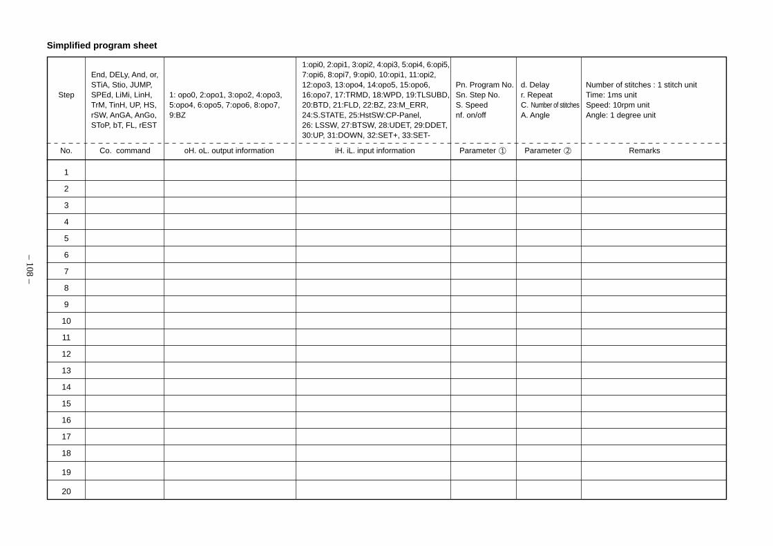
– 108 –
1
2
3
4
5
6
7
8
9
10
11
12
13
14
15
16
17
18
19
20
Simplified program sheet
1:opi0, 2:opi1, 3:opi2, 4:opi3, 5:opi4, 6:opi5,End, DELy, And, or, 7:opi6, 8:opi7, 9:opi0, 10:opi1, 11:opi2,STiA, Stio, JUMP, 12:opo3, 13:opo4, 14:opo5, 15:opo6, Pn. Program No. d. Delay Number of stitches : 1 stitch unit
Step SPEd, LiMi, LinH, 1: opo0, 2:opo1, 3:opo2, 4:opo3, 16:opo7, 17:TRMD, 18:WPD, 19:TLSUBD, Sn. Step No. r. Repeat Time: 1ms unitTrM, TinH, UP, HS, 5:opo4, 6:opo5, 7:opo6, 8:opo7, 20:BTD, 21:FLD, 22:BZ, 23:M_ERR, S. Speed C. Number of stitches Speed: 10rpm unitrSW, AnGA, AnGo, 9:BZ 24:S.STATE, 25:HstSW:CP-Panel, nf. on/off A. Angle Angle: 1 degree unitSToP, bT, FL, rEST 26: LSSW, 27:BTSW, 28:UDET, 29:DDET,
30:UP, 31:DOWN, 32:SET+, 33:SET-
No. Co. command oH. oL. output information iH. iL. input information Parameter 1 Parameter 2 Remarks

– 109 –
(2) Solenoid Connector for lifting presser foot
Name of signal Pin NO.
FLD 1
FL COM 2
Layout of CN37 pins
10. CONNECTOR CONNECTION DIAGRAM
Name of signal Pin NO.
TRMD 1
TRMCOM 8
BTD 6
BTDCOM 13
WPD 2
WPDCOM 9
SUB BTD 7
SUBCOM 14
OP_IN (FLSW) 3
FLSW 4
BTSW 5
BTSWRTN 12
GND 11
FG 10
Layout of CN36 pins
8 9 10 11 12 13 14
1 2 3 4 5 6 7
CN36
CN36
1
8
6
132
9
7
14
4
11
5
12
3
10
TRM (Thread trimming)
Approx. 7.5Ω
BT (Touch back)
Approx. 6.5Ω
WP (Wiper)
Approx. 8.5Ω
BT SW Touch back switch
(1) Solenoid for machine head
1
2
FL (Presser foot lifter)Approx. 5.4Ω
CN37
1
2CN37
Pin side (insertion side)
(Caution) 1. Because the FL (foot lifter) output connector of CN37varies with the specifications of the machine head, re-fer to “14. INPUT/OUTPUT CHART” for details.
(Caution) 2. Because the connector of CN36 and CN37 may operate as air output (+24V) depending on thespecifications of the machine head, refer to “14. INPUT/OUTPUT CHART” for derails.
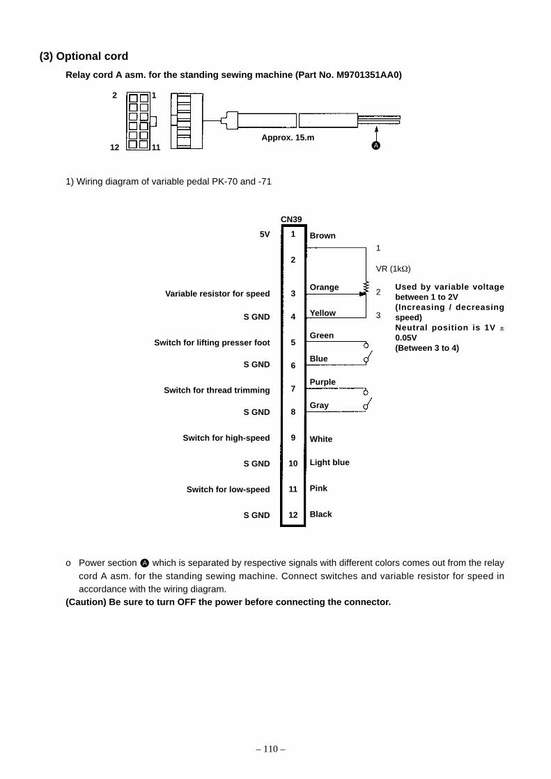
– 110 –
1
VR (1kΩ)
2
3
(3) Optional cord
Relay cord A asm. for the standing sewing machine (Part No. M9701351AA0)
1) Wiring diagram of variable pedal PK-70 and -71
o Power section A which is separated by respective signals with different colors comes out from the relaycord A asm. for the standing sewing machine. Connect switches and variable resistor for speed inaccordance with the wiring diagram.
(Caution) Be sure to turn OFF the power before connecting the connector.
Used by variable voltagebetween 1 to 2V(Increasing / decreasingspeed)Neutral position is 1V ±0.05V(Between 3 to 4)
2 1
12 11Approx. 15.m
A
CN39
1
2
3
4
5
6
7
8
9
10
11
12
Brown
Orange
Yellow
Green
Blue
Purple
Gray
White
Light blue
Pink
Black
5V
Variable resistor for speed
S GND
Switch for lifting presser foot
S GND
Switch for thread trimming
S GND
Switch for high-speed
S GND
Switch for low-speed
S GND
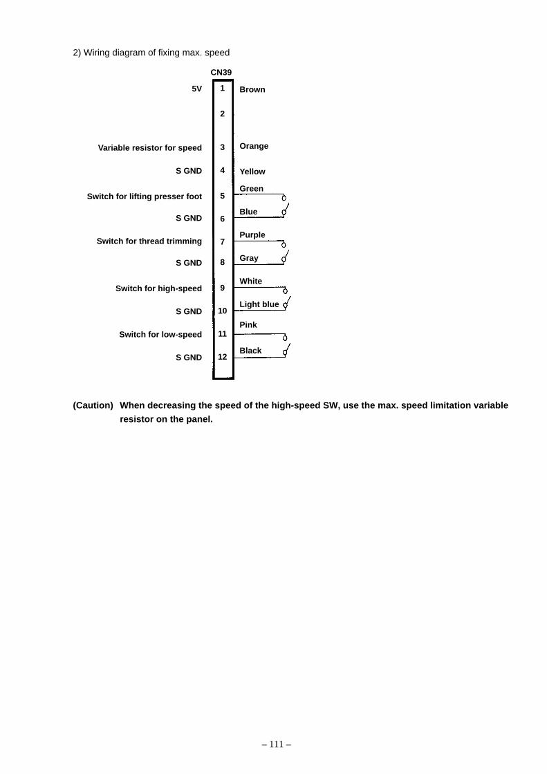
– 111 –
2) Wiring diagram of fixing max. speed
(Caution) When decreasing the speed of the high-speed SW, use the max. speed limitation variable
resistor on the panel.
Brown
Orange
Yellow
Green
Blue
Purple
Gray
White
Light blue
Pink
Black
5V
Variable resistor for speed
S GND
Switch for lifting presser foot
S GND
Switch for thread trimming
S GND
Switch for high-speed
S GND
Switch for low-speed
S GND
CN39
1
2
3
4
5
6
7
8
9
10
11
12

– 112 –
11. MAINTENANCE(1) Replacing the fuse
1) Press the OFF button of the power switch to turn
OFF the power after confirming that the sewing ma-
chine has stopped.
2) Draw out the power cord coming from the power plug
socket after confirming that the power switch is turned
OFF. Perform the work of step 3) after confirming
that the power has been cut and it has passed for 5
minutes or more.
3) Loosen setscrew in front cover .
4) Pressing the side of front cover in the direction of
the arrow, open the front cover toward you.
(Caution) Be sure to open / close the front cover
with your hands.
WARNING :To prevent personal injuries caused by electric shock hazards or abrupt start of the sewing machine,
remove the cover after turning OFF the power switch and a lapse of 5 minutes or more. To prevent personal
injuries, when a fuse has blown out, be sure to replace it with a new one with the same capacity after
turning OFF the power switch and removing the cause of the blown-out of the fuse.
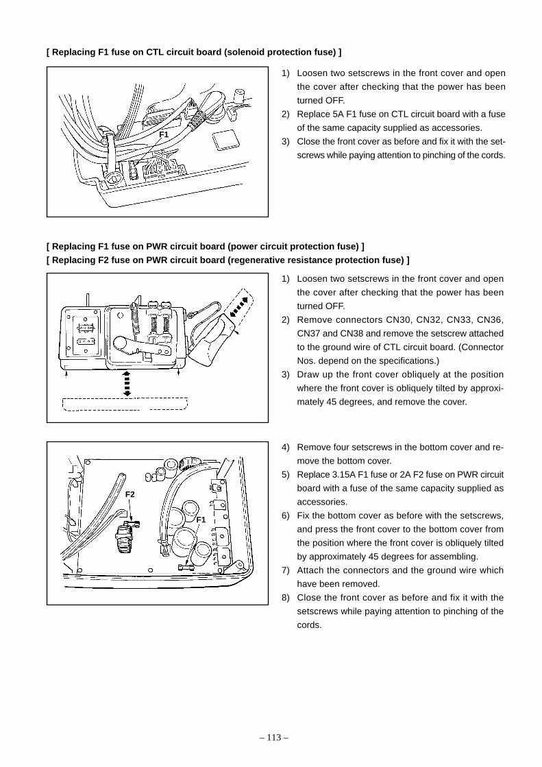
– 113 –
[ Replacing F1 fuse on CTL circuit board (solenoid protection fuse) ]
1) Loosen two setscrews in the front cover and open
the cover after checking that the power has been
turned OFF.
2) Replace 5A F1 fuse on CTL circuit board with a fuse
of the same capacity supplied as accessories.
3) Close the front cover as before and fix it with the set-
screws while paying attention to pinching of the cords.
[ Replacing F1 fuse on PWR circuit board (power circuit protection fuse) ]
[ Replacing F2 fuse on PWR circuit board (regenerative resistance protection fuse) ]
1) Loosen two setscrews in the front cover and open
the cover after checking that the power has been
turned OFF.
2) Remove connectors CN30, CN32, CN33, CN36,
CN37 and CN38 and remove the setscrew attached
to the ground wire of CTL circuit board. (Connector
Nos. depend on the specifications.)
3) Draw up the front cover obliquely at the position
where the front cover is obliquely tilted by approxi-
mately 45 degrees, and remove the cover.
4) Remove four setscrews in the bottom cover and re-
move the bottom cover.
5) Replace 3.15A F1 fuse or 2A F2 fuse on PWR circuit
board with a fuse of the same capacity supplied as
accessories.
6) Fix the bottom cover as before with the setscrews,
and press the front cover to the bottom cover from
the position where the front cover is obliquely tilted
by approximately 45 degrees for assembling.
7) Attach the connectors and the ground wire which
have been removed.
8) Close the front cover as before and fix it with the
setscrews while paying attention to pinching of the
cords.
F2
F1
F1
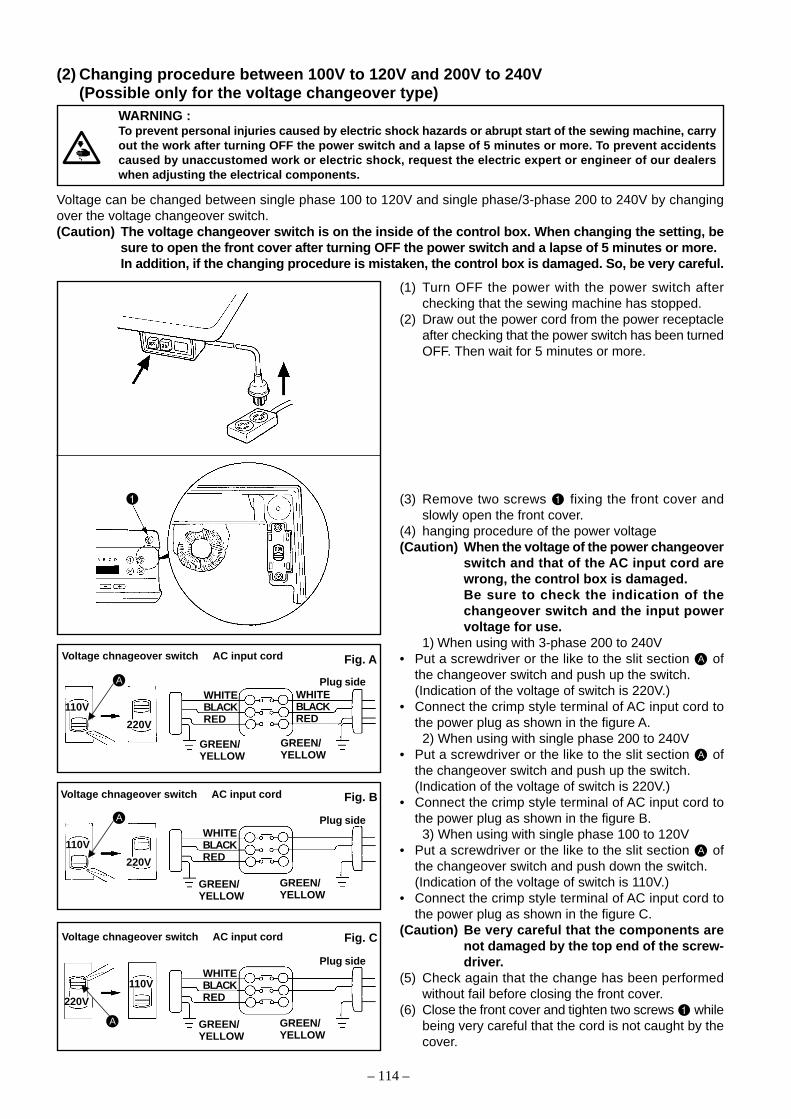
– 114 –
(2) Changing procedure between 100V to 120V and 200V to 240V(Possible only for the voltage changeover type)
(1) Turn OFF the power with the power switch afterchecking that the sewing machine has stopped.
(2) Draw out the power cord from the power receptacleafter checking that the power switch has been turnedOFF. Then wait for 5 minutes or more.
(3) Remove two screws fixing the front cover andslowly open the front cover.
(4) hanging procedure of the power voltage(Caution) When the voltage of the power changeover
switch and that of the AC input cord arewrong, the control box is damaged.Be sure to check the indication of thechangeover switch and the input powervoltage for use.
1) When using with 3-phase 200 to 240V• Put a screwdriver or the like to the slit section A of
the changeover switch and push up the switch.(Indication of the voltage of switch is 220V.)
• Connect the crimp style terminal of AC input cord tothe power plug as shown in the figure A.
2) When using with single phase 200 to 240V• Put a screwdriver or the like to the slit section A of
the changeover switch and push up the switch.(Indication of the voltage of switch is 220V.)
• Connect the crimp style terminal of AC input cord tothe power plug as shown in the figure B.
3) When using with single phase 100 to 120V• Put a screwdriver or the like to the slit section A of
the changeover switch and push down the switch.(Indication of the voltage of switch is 110V.)
• Connect the crimp style terminal of AC input cord tothe power plug as shown in the figure C.
(Caution) Be very careful that the components arenot damaged by the top end of the screw-driver.
(5) Check again that the change has been performedwithout fail before closing the front cover.
(6) Close the front cover and tighten two screws whilebeing very careful that the cord is not caught by thecover.
Plug sideWHITEBLACKRED
GREEN/YELLOW
Voltage can be changed between single phase 100 to 120V and single phase/3-phase 200 to 240V by changingover the voltage changeover switch.(Caution) The voltage changeover switch is on the inside of the control box. When changing the setting, be
sure to open the front cover after turning OFF the power switch and a lapse of 5 minutes or more.In addition, if the changing procedure is mistaken, the control box is damaged. So, be very careful.
A
Fig. A
110V
220V
Plug sideA
Fig. B
110V
220V
Plug side
Fig. C
A
220V
110V
Voltage chnageover switch AC input cord
Voltage chnageover switch AC input cord
Voltage chnageover switch AC input cord
WHITEBLACKRED
WHITEBLACKRED
GREEN/YELLOW
GREEN/YELLOW
GREEN/YELLOW
WHITEBLACKRED
GREEN/YELLOW
GREEN/YELLOW
WARNING :To prevent personal injuries caused by electric shock hazards or abrupt start of the sewing machine, carryout the work after turning OFF the power switch and a lapse of 5 minutes or more. To prevent accidentscaused by unaccustomed work or electric shock, request the electric expert or engineer of our dealerswhen adjusting the electrical components.
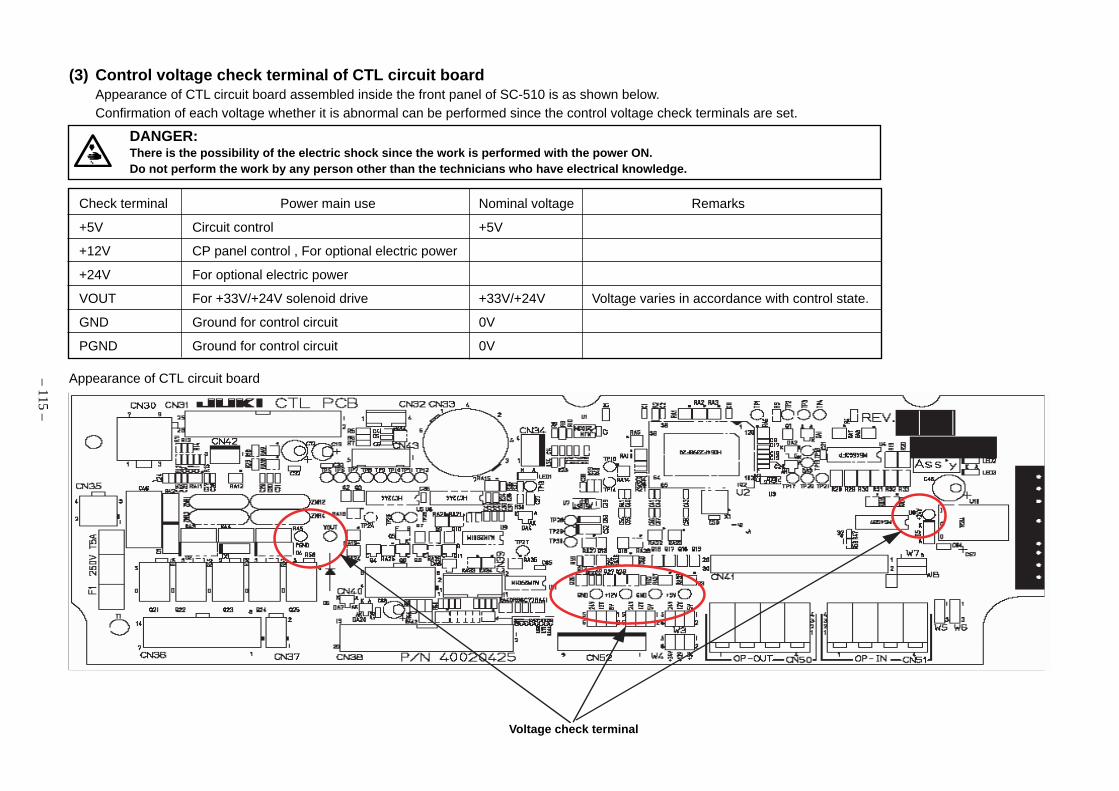
– 115 –
(3) Control voltage check terminal of CTL circuit boardAppearance of CTL circuit board assembled inside the front panel of SC-510 is as shown below.Confirmation of each voltage whether it is abnormal can be performed since the control voltage check terminals are set.
Check terminal Power main use Nominal voltage Remarks
+5V Circuit control +5V
+12V CP panel control , For optional electric power
+24V For optional electric power
VOUT For +33V/+24V solenoid drive +33V/+24V Voltage varies in accordance with control state.
GND Ground for control circuit 0V
PGND Ground for control circuit 0V
Appearance of CTL circuit board
Voltage check terminal
DANGER:There is the possibility of the electric shock since the work is performed with the power ON.Do not perform the work by any person other than the technicians who have electrical knowledge.
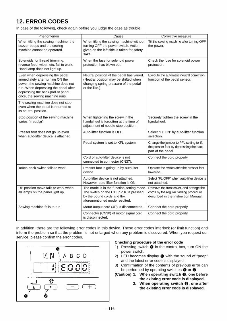
– 116 –
12. ERROR CODESIn case of the following, check again before you judge the case as trouble.
Phenomenon Cause Corrective measure
When tilting the sewing machine, the When tilting the sewing machine without Tilt the sewing machine after turning OFFbuzzer beeps and the sewing turning OFF the power switch, Action the power.machine cannot be operated. given on the left side is taken for safety
sake.
Solenoids for thread trimming, When the fuse for solenoid power Check the fuse for solenoid powerreverse feed, wiper, etc. fail to work. protection has blown out. protection.Hand lamp does not light up.
Even when depressing the pedal Neutral position of the pedal has varied. Execute the automatic neutral correctionimmediately after turning ON the (Neutral position may be shifted when function of the pedal sensor.power, the sewing machine does not changing spring pressure of the pedalrun. When depressing the pedal after or the like.)depressing the back part of pedalonce, the sewing machine runs.
The sewing machine does not stopeven when the pedal is returned toits neutral position.
Stop position of the sewing machine When tightening the screw in the Securely tighten the screw in thevaries (irregular). handwheel is forgotten at the time of handwheel.
adjustment of needle stop position.
Presser foot does not go up even Auto-lifter function is OFF. Select “FL ON” by auto-lifter functionwhen auto-lifter device is attached. selection.
Pedal system is set to KFL system. Change the jumper to PFL setting to liftthe presser foot by depressing the backpart of the pedal.
Cord of auto-lifter device is not Connect the cord properly.connected to connector (CN37).
Touch-back switch fails to work. Presser foot is going up by auto-liter Operate the switch after the presser footdevice. lowered.
Auto-lifter device is not attached. Select “FL OFF” when auto-lifter device isHowever, auto-lifter function is ON. not attached.
UP position move fails to work when The mode is in the function setting mode. Remove the front cover, and arrange theall lamps on the panel light up. The switch on the CTL p.c.b. is pressed cords by the regular binding procedure
by the bound cords and the described in the Instruction Manual.aforementioned mode resulted.
Sewing machine fails to run. Motor output cord (4P) is disconnected. Connect the cord properly.
Connector (CN30) of motor signal cord Connect the cord properly.is disconnected.
In addition, there are the following error codes in this device. These error codes interlock (or limit function) andinform the problem so that the problem is not enlarged when any problem is discovered. When you request ourservice, please confirm the error codes.
Checking procedure of the error code1) Pressing switch in the control box, turn ON the
power switch.2) LED becomes display with the sound of “peep”
and the latest error code is displayed.3) Confirmation of the contents of previous error can
be performed by operating switches or .(Caution) 1. When operating switch , one before
the existing error code is displayed.2. When operating switch , one after
the existing error code is displayed.

– 117 –
No. Description of error detected Cause of occurrence expected Items to be checked
SmartMedia cover open • The SmartMedia slot is open • Close the cover of the slot
E000 Execution of data initialization • When the machine head is changed.
(This is not the error.) • When the initialization operation is executed
E003 Disconnection of synchronizer • When position detection signal is not input • Check the synchronizer connector (CN33,
connector from the sewing machine head synchronizer. CN43) for loose connection and disconnection.
E004 Synchronizer lower position sensor failure • When the synchronizer has broken. • Check whether the synchronizer cord has broken
E005 Synchronizer upper position sensor failure since the cord is caught in the machine head.
E007 Overload of motor • When the machine head is locked. • Check whether the thread has been entangled
• When sewing extra-heavy material beyond in the motor pulley.
the guarantee of the machine head. • Check the motor output connector (4P) for loose
• When the motor does not run. connection and disconnection.
• Motor or driver is broken. • Check whether there is any holdup when turning
the motor by hand.
E008 Machine head connector • When the machine head connector is not • Check the machine head connector (CN32)
failure(Resistance pack) properly read. for loose connection and disconnection.
E011 A SmartMedia card uninserted • A SmartMedia card has not been inserted. • Turn OFF the power.
E012 Read error • Data on a SmartMedia card cannot be read. • Turn OFF the power.
E013 Write error • Data cannot be written into a SmartMedia • Turn OFF the power.
card.
E014 Write protection • The SmartMedia is write-protected. • Turn OFF the power.
E015 Format error • The SmartMedia is unformattable. • Turn OFF the power.
E016 Beyond external media capacity • Short of SmartMedia capacity • Turn OFF the power.
E019 Beyond file size • The file is too large. • Turn OFF the power.
E032 File compatibility error • The file is not compatible. • Turn OFF the power.
E302 Tilt detection • When tilt detection switch is inputted with • Check whether machine head is tilted without
(MF : thread trimmer knife sensor) the power ON. turning OFF the power switch (operation of
(At the time of safety switch • Position of thread trimmer knife is improper. sewing machine is prohibited for safety).
operation) • Check whether tilt detection switch cord is caught
in the machine.
• Check whether tilt detection switch lever is
caught in the machine.
E331 Tape cutter (TC03) • Defective cutter sensor • Is air pressure appropriate?
Cutter sensor simultaneously
enabled
E332 Tape cutter (TC03) • Defective assembly • Is air pressure appropriate?
Cutter sensor simultaneously
disabled
E499 Simplified program data error • Command parameter data is out of the range. • Enter the simplified program again.
• Disable the simplified prgram.
E704 Type error of simplified program • Adifferent type is entered for the program • Turn off the power.
or sewing machine data or data.
E730 Encoder failure • When the motor signal is not properly • Check the motor signal connector (CN30) for
E731 Motor hole sensor failure inputted. loose connection and disconnection.
• Check whether the motor signal cord has broken
since the cord is caught in the machine head.
E733 Motor reverse rotation The motor rotates at the speed of more than • Encoder wiring of the main shaft motor is
500rpm in a direction opposite to that of wrong.
indication. • Power wiring of the main shaft motor is
wrong.
(1) Error code list
*
***
*****
(Caution) Items marked with * are applicable only to IP-100E.

– 118 –
No. Description of error detected Cause of occurrence expected Items to be checked
E811 Overvoltage • When voltage higher than guaranteed one • Check whether the applied power voltage is
is inputted. higher than the rated voltage + (plus) 10% or more.
• When 220V has been inputted at 110V • Check whether 110V/220V changeover switch is
setting improperly set.
• 400V is applied to the box of 220V (230V). • In the aforementioned cases, POWER p.c.b
is broken.
E813 Low voltage • When voltage lower than guaranteed one • Check whether the voltage is lower than the
is inputted. rated voltage – (minus) 10% or less.
• When 110V has been inputted at 220V setting. • Check whether 110V/220V changeover switch
• 110V is applied to the box of 220V. is improperly set.
• Inner circuit is broken by the applied • Check whether fuse or regenerative resistance
overvoltage is broken.
E906 Operation panel transmission • Disconnection of operation panel cord • Check the operation panel connector (CN38)
failure • Operation panel has broken. for loose connection and disconnection.
• Check whether the operation panel cord has
broken since the cord is caught in the
machine head.
E915 Communication error • Cord of operation panel disconnected • Make sure that the operation panel connector
(between operation panel and • Operation panel damaged (CN121) is secured.
IPOP (expansion) board) • IPOP board poorly connected or damaged • Make sure that there is no damage to the cord
due to being caught by the top of the operation
panel.
• Make sure that the IPOP board and the con-
nector are secured.
E916 Communication error • IPOP board poorly connected or damaged • Make sure that the IPOP board and the
(between IPOP (expansion) board connector are secured.
and CTL (front cover) board)
E924 Motor driver failure • Motor driver has broken.
E942 EEPROM error • Data unwritable into EEPROM • Turn off the power.
*
*
(Caution) Items marked with * are applicable only to IP-100E.
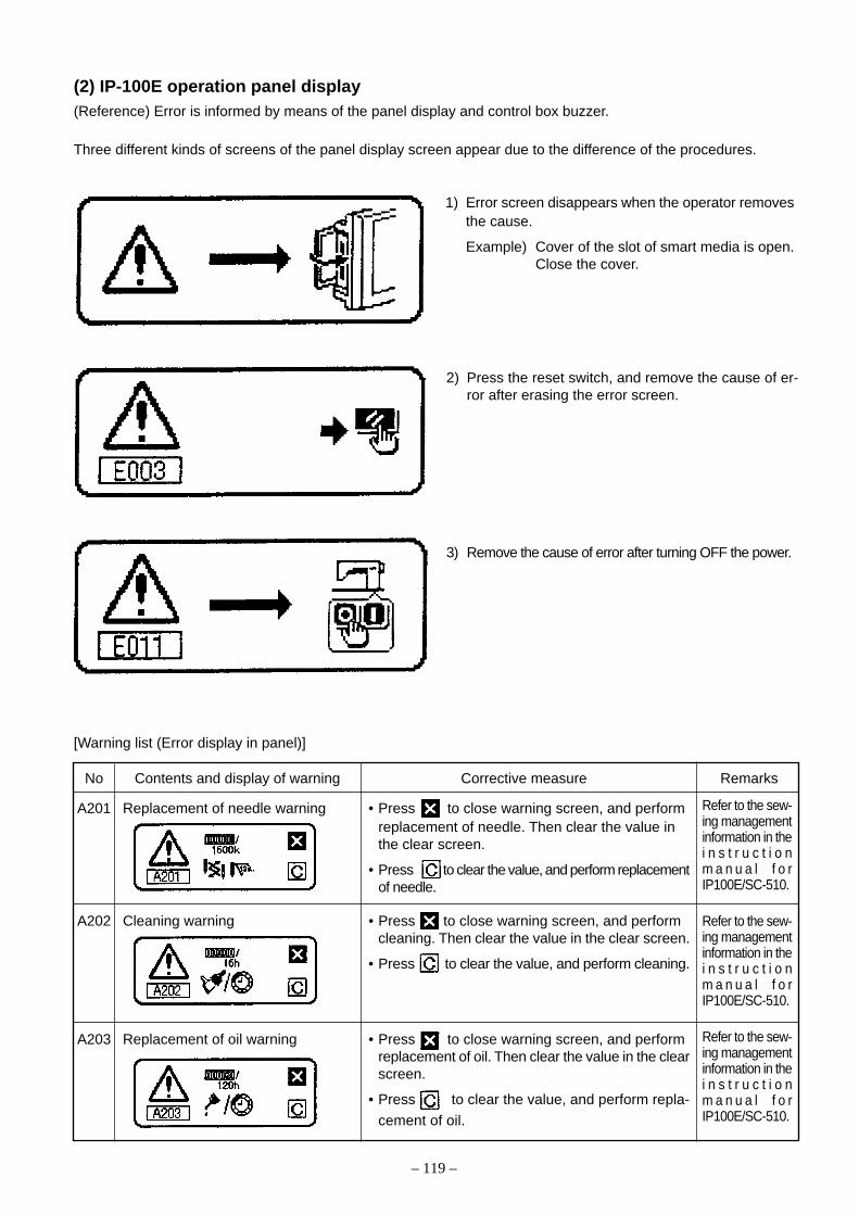
– 119 –
(2) IP-100E operation panel display(Reference) Error is informed by means of the panel display and control box buzzer.
Three different kinds of screens of the panel display screen appear due to the difference of the procedures.
1) Error screen disappears when the operator removesthe cause.
Example) Cover of the slot of smart media is open.Close the cover.
[Warning list (Error display in panel)]
No Contents and display of warning Corrective measure Remarks
A201 Replacement of needle warning • Press to close warning screen, and performreplacement of needle. Then clear the value inthe clear screen.
• Press to clear the value, and perform replacementof needle.
A202 Cleaning warning • Press to close warning screen, and performcleaning. Then clear the value in the clear screen.
• Press to clear the value, and perform cleaning.
A203 Replacement of oil warning • Press to close warning screen, and performreplacement of oil. Then clear the value in the clearscreen.
• Press to clear the value, and perform repla-
cement of oil.
2) Press the reset switch, and remove the cause of er-ror after erasing the error screen.
3) Remove the cause of error after turning OFF the power.
Refer to the sew-ing managementinformation in thei n s t r u c t i o nm a n u a l f o rIP100E/SC-510.
Refer to the sew-ing managementinformation in thei n s t r u c t i o nm a n u a l f o rIP100E/SC-510.
Refer to the sew-ing managementinformation in thei n s t r u c t i o nm a n u a l f o rIP100E/SC-510.
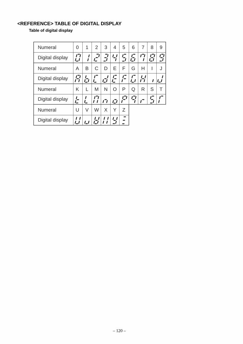
– 120 –
Numeral 0 1 2 3 4 5 6 7 8 9
Numeral A B C D E F G H I J
Numeral K L M N O P Q R S T
Numeral U V W X Y Z
Digital display
Digital display
Digital display
Digital display
<REFERENCE> TABLE OF DIGITAL DISPLAYTable of digital display
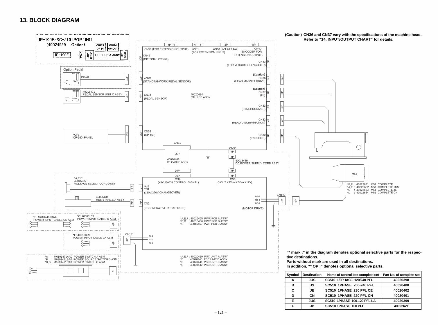
40020424CTL PCB ASSY
*A,E,F : 40016465 PWR PCB A ASSY*B,D : 40016466 PWR PCB B ASSY*C : 40016467 PWR PCB C ASSY
*A,E,F : 40020439 PSC UNIT A ASSY*B : 40020440 PSC UNIT B ASSY*C : 40020441 PSC UNIT C ASSY*D : 40020442 PSC UNIT D ASSY
CN35
CN4 CN3
40016468I/F CABLE ASSY 40016469
M51
DC POWER SUPPLY CORD ASSY
*A,E,F:40016522VOLTAGE SELECT CORD ASSY
*A,ECN12P
26P 4P
4P
CN22P
40006134RESISTANCE A ASSY
CN141T3-1
T3-2
T3-3
4P
4P4P
*C: 40006139POWER INPUT CABLE D ASM
*C: M6102461DAAPOWER INPUT CABLE CE ASM
4P
*E: 40012009
CN140T15-3
T15-1
T15-2
4P 4P
2P2P
26P
26P
4P
4P
9P4P
(VOUT +33Vor+24Vor+12V)
7P
CN34
CN38
CN31
(CP-160)20P
20P
*OP:CP-160 PANEL
4P 4P
40016471PEDAL SENSOR UNIT C ASSY
CN43 5P2P
14P
9P4P
7P2P
14P
30P CN41
(OPTONAL PCB I/F)
(PEDAL SENSOR)
(STANDING-WORK PEDAL SENSOR)
*B,F : 40022651 M51 COMPLETE*A,E : 40022652 M51 COMPLETE JUS*C : 40022653 M51 COMPLETE JE*D : 40022654 M51 COMPLETE CN
8P3PCN40
CN36(Caution)
(Caution)CN37
(FL)
CN33
CN32
CN30
4P 4 4P 4
CN50 (FOR EXTENSION OUTPUT) CN51 (FOR EXTENSION INPUT)
CN42 (SAFETY SW)(ENCODER FOR
EXTENSION OUTPUT)
(FOR MITSUBISHI ENCODER)
(ENCODER)
(HEAD MAGNET DRIVE)
(SYNCHRONIZER)
(HEAD DISCRIMINATION)
(+5V, EACH CONTROL SIGNAL)
(110V/220V CHANGEOVER)
(REGENERATIVE RESISTANCE) (MOTOR DRIVE)
*A : M6101471AA0 POWER SWITCH A ASM *F : M6101471BA0 POWER SOURCE SWITCH B ASM*B,D : M6101471CA0 POWER SWITCH C ASM
12PPK-70
12P CN39
Option Pedal
POWER INPUT CABLE LA ASM
13. BLOCK DIAGRAM
– 121 –
“* mark :” in the diagram denotes optional selective parts for the respec-tive destinations.Parts without mark are used in all destinations.In addition, “* OP :” denotes optional selective parts.
Symbol Destination Name of control box complete set Part No. of complete set
A JUS SC510 1/3PHASE 120/240 PFL 40020398
B JS SC510 1PHASE 200-240 PFL 40020400
C JE SC510 1PHASE 230 PFL CE 40020402
D CN SC510 1PHASE 220 PFL CN 40020401
E JUS SC510 1PHASE 100-120 PFL LA 40020399
F JP SC510 1PHASE 100 PFL 40022621
(Caution) CN36 and CN37 vary with the specifications of the machine head.Refer to “14. INPUT/OUTPUT CHART” for details.
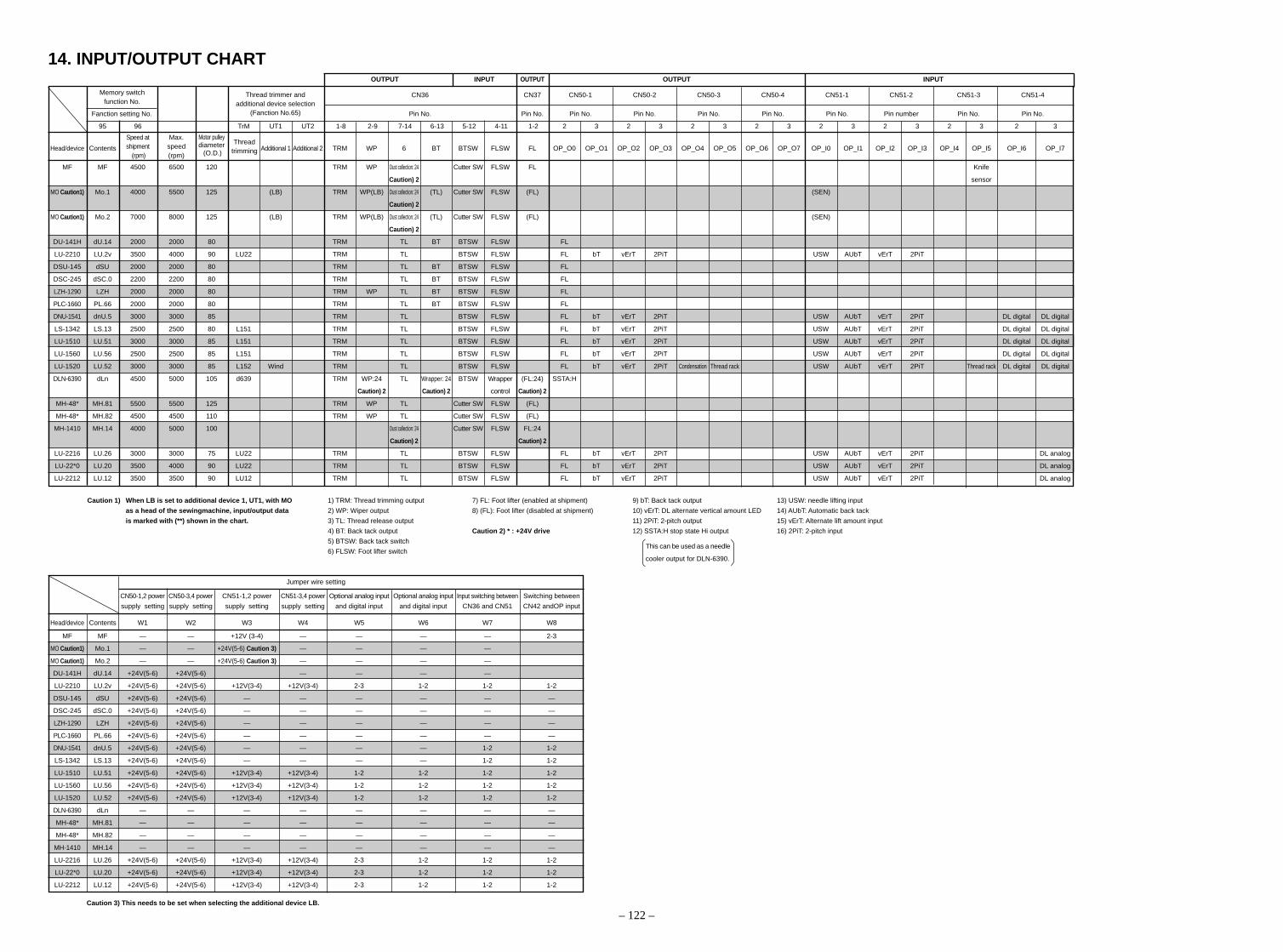
– 122 –
14. INPUT/OUTPUT CHART
Caution 1) When LB is set to additional device 1, UT1, with MO 1) TRM: Thread trimming output 7) FL: Foot lifter (enabled at shipment) 9) bT: Back tack output 13) USW: needle lifting input
as a head of the sewingmachine, input/output data 2) WP: Wiper output 8) (FL): Foot lifter (disabled at shipment) 10) vErT: DL alternate vertical amount LED 14) AUbT: Automatic back tack
is marked with (**) shown in the chart. 3) TL: Thread release output 11) 2PiT: 2-pitch output 15) vErT: Alternate lift amount input
4) BT: Back tack output Caution 2) * : +24V drive 12) SSTA:H stop state Hi output 16) 2PiT: 2-pitch input
5) BTSW: Back tack switch
6) FLSW: Foot lifter switch
Motor pulleydiameter (O.D.)
Speed atshipment
(rpm)
Max.speed(rpm)
Thread trimmer andadditional device selection
(Fanction No.65)
Caution 3) This needs to be set when selecting the additional device LB.
Jumper wire setting
CN50-1,2 power CN50-3,4 power CN51-1,2 power CN51-3,4 power Optional analog input Optional analog input Input switching between Switching between
supply setting supply setting supply setting supply setting and digital input and digital input CN36 and CN51 CN42 andOP input
Head/device Contents W1 W2 W3 W4 W5 W6 W7 W8
MF MF — — +12V (3-4) — — — — 2-3
MO Caution1) Mo.1 — — +24V(5-6) Caution 3) — — — —
MO Caution1) Mo.2 — — +24V(5-6) Caution 3) — — — —
DU-141H dU.14 +24V(5-6) +24V(5-6) — — — —
LU-2210 LU.2v +24V(5-6) +24V(5-6) +12V(3-4) +12V(3-4) 2-3 1-2 1-2 1-2
DSU-145 dSU +24V(5-6) +24V(5-6) — — — — — —
DSC-245 dSC.0 +24V(5-6) +24V(5-6) — — — — — —
LZH-1290 LZH +24V(5-6) +24V(5-6) — — — — — —
PLC-1660 PL.66 +24V(5-6) +24V(5-6) — — — — — —
DNU-1541 dnU.5 +24V(5-6) +24V(5-6) — — — — 1-2 1-2
LS-1342 LS.13 +24V(5-6) +24V(5-6) — — — — 1-2 1-2
LU-1510 LU.51 +24V(5-6) +24V(5-6) +12V(3-4) +12V(3-4) 1-2 1-2 1-2 1-2
LU-1560 LU.56 +24V(5-6) +24V(5-6) +12V(3-4) +12V(3-4) 1-2 1-2 1-2 1-2
LU-1520 LU.52 +24V(5-6) +24V(5-6) +12V(3-4) +12V(3-4) 1-2 1-2 1-2 1-2
DLN-6390 dLn — — — — — — — —
MH-48* MH.81 — — — — — — — —
MH-48* MH.82 — — — — — — — —
MH-1410 MH.14 — — — — — — — —
LU-2216 LU.26 +24V(5-6) +24V(5-6) +12V(3-4) +12V(3-4) 2-3 1-2 1-2 1-2
LU-22*0 LU.20 +24V(5-6) +24V(5-6) +12V(3-4) +12V(3-4) 2-3 1-2 1-2 1-2
LU-2212 LU.12 +24V(5-6) +24V(5-6) +12V(3-4) +12V(3-4) 2-3 1-2 1-2 1-2
Memory switchfunction No.
Threadtrimming
OUTPUT INPUT OUTPUT OUTPUT INPUT
CN36 CN37 CN50-1 CN50-2 CN50-3 CN50-4 CN51-1 CN51-2 CN51-3 CN51-4
Fanction setting No. Pin No. Pin No. Pin No. Pin No. Pin No. Pin No. Pin No. Pin number Pin No. Pin No.
95 96 TrM UT1 UT2 1-8 2-9 7-14 6-13 5-12 4-11 1-2 2 3 2 3 2 3 2 3 2 3 2 3 2 3 2 3
Head/device Contents Additional 1 Additional 2 TRM WP 6 BT BTSW FLSW FL OP_O0 OP_O1 OP_O2 OP_O3 OP_O4 OP_O5 OP_O6 OP_O7 OP_I0 OP_I1 OP_I2 OP_I3 OP_I4 OP_I5 OP_I6 OP_I7
MF MF 4500 6500 120 TRM WP Dust collection: 24 Cutter SW FLSW FL Knife
Caution) 2 sensor
MO Caution1) Mo.1 4000 5500 125 (LB) TRM WP(LB) Dust collection: 24 (TL) Cutter SW FLSW (FL) (SEN)
Caution) 2
MO Caution1) Mo.2 7000 8000 125 (LB) TRM WP(LB) Dust collection: 24 (TL) Cutter SW FLSW (FL) (SEN)
Caution) 2
DU-141H dU.14 2000 2000 80 TRM TL BT BTSW FLSW FL
LU-2210 LU.2v 3500 4000 90 LU22 TRM TL BTSW FLSW FL bT vErT 2PiT USW AUbT vErT 2PiT
DSU-145 dSU 2000 2000 80 TRM TL BT BTSW FLSW FL
DSC-245 dSC.0 2200 2200 80 TRM TL BT BTSW FLSW FL
LZH-1290 LZH 2000 2000 80 TRM WP TL BT BTSW FLSW FL
PLC-1660 PL.66 2000 2000 80 TRM TL BT BTSW FLSW FL
DNU-1541 dnU.5 3000 3000 85 TRM TL BTSW FLSW FL bT vErT 2PiT USW AUbT vErT 2PiT DL digital DL digital
LS-1342 LS.13 2500 2500 80 L151 TRM TL BTSW FLSW FL bT vErT 2PiT USW AUbT vErT 2PiT DL digital DL digital
LU-1510 LU.51 3000 3000 85 L151 TRM TL BTSW FLSW FL bT vErT 2PiT USW AUbT vErT 2PiT DL digital DL digital
LU-1560 LU.56 2500 2500 85 L151 TRM TL BTSW FLSW FL bT vErT 2PiT USW AUbT vErT 2PiT DL digital DL digital
LU-1520 LU.52 3000 3000 85 L152 Wind TRM TL BTSW FLSW FL bT vErT 2PiT Condensation Thread rack USW AUbT vErT 2PiT Thread rack DL digital DL digital
DLN-6390 dLn 4500 5000 105 d639 TRM WP:24 TL Wrapper: 24 BTSW Wrapper (FL:24) SSTA:H
Caution) 2 Caution) 2 control Caution) 2
MH-48* MH.81 5500 5500 125 TRM WP TL Cutter SW FLSW (FL)
MH-48* MH.82 4500 4500 110 TRM WP TL Cutter SW FLSW (FL)
MH-1410 MH.14 4000 5000 100 Dust collection: 24 Cutter SW FLSW FL:24
Caution) 2 Caution) 2
LU-2216 LU.26 3000 3000 75 LU22 TRM TL BTSW FLSW FL bT vErT 2PiT USW AUbT vErT 2PiT DL analog
LU-22*0 LU.20 3500 4000 90 LU22 TRM TL BTSW FLSW FL bT vErT 2PiT USW AUbT vErT 2PiT DL analog
LU-2212 LU.12 3500 3500 90 LU12 TRM TL BTSW FLSW FL bT vErT 2PiT USW AUbT vErT 2PiT DL analog
This can be used as a needle
cooler output for DLN-6390.

®
MARKETING & SALES H.Q.8-2-1, KOKURYO-CHO,CHOFU-SHI, TOKYO 182-8655, JAPANPHONE : (81)3-3480-2357 • 2358FAX : (81)3-3430-4909 • 4914
Copyright © 2005 JUKI CORPORATION.
All rights reserved throughout the world.
Please do not hesitate to contact our distributors or agents in your area for further information when necessary.* The description covered in this engineer's manual is subject to change for improvement of the
commodity without notice.05 · 03 Printed in Japan (E)
This manual uses environment-friendly soyink.
The environmental management system to promote and conduct1the technological and technical research, the development and
design of the products in which the environmental impact is consid-ered,
2the conservation of the energy and resources, and the recycling, inthe research, development, design, distribution, sale and mainte-nance service of the industrial sewing machines, household sew-ing machines and industrial-use robots, etc. and in the sale andmaintenance service of data entry system and in the purchase, dis-tribution and sale of the household commodities including thehealthcare products.


