Date post: | 16-Apr-2018 |
Category: |
Documents |
Upload: | truongtruc |
View: | 223 times |
Download: | 3 times |
DESCRIPTION
1© 2016 Maxitrol Company, All Rights Reserved
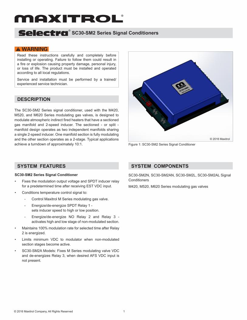
The SC30-SM2 Series signal conditioner, used with the M420, M520, and M620 Series modulating gas valves, is designed to modulate atmospheric indirect fired heaters that have a sectioned gas manifold and 2-speed inducer. The sectioned - or split - manifold design operates as two independent manifolds sharing a single 2-speed inducer. One manifold section is fully modulating and the other section operates as a 2-stage. Typical applications achieve a turndown of approximately 10:1. Figure 1: SC30-SM2 Series Signal Conditioner
SC30-SM2 Series Signal Conditioners
Read these instructions carefully and completely before installing or operating. Failure to follow them could result in a fire or explosion causing property damage, personal injury, or loss of life. The product must be installed and operated according to all local regulations.
Service and installation must be performed by a trained/experienced service technician.
SYSTEM FEATURESSC30-SM2 Series Signal Conditioner
• Fixes the modulation output voltage and SPDT inducer relay for a predetermined time after receiving EST VDC input.
• Conditions temperature control signal to:
- Control Maxitrol M Series modulating gas valve.
- Energize/de-energize SPDT Relay 1 - sets inducer speed to high or low position.
- Energize/de-energize NO Relay 2 and Relay 3 - activates high and low stage of non-modulated section.
• Maintains 100% modulation rate for selected time after Relay 2 is energized.
• Limits minimum VDC to modulator when non-modulated section stages become active.
• SC30-SM2A Models: Fixes M Series modulating valve VDC and de-energizes Relay 3, when desired AFS VDC input is not present.
© 2016 Maxitrol
SYSTEM COMPONENTS
SC30-SM2N, SC30-SM2AN, SC30-SM2L, SC30-SM2AL Signal Conditioners
M420, M520, M620 Series modulating gas valves
SC30-SM2 Series Signal Conditioners
2© 2016 Maxitrol Company, All Rights Reserved
JUMPER AND DIP SWITCH SETTINGS
J1 Connects T2 to T5 24 VAC - shunt installedDry contact - no shuntJ2 Connects T2 to T8
J3 Connects T9 to T10 R2 output to R3 input
SPECIFICATIONSTemperature Control (TC) Signal Input0 - 10 VDC, 2 - 10 VDCImpedance 100k ohms (nominal)0 - 20 mA, 4 - 20 mAImpedance 500k ohms (nominal)
Modulating Gas Valve OutputVoltage range: 2 - 15, 18 max (REF: NAT Gas) - “N” Models 2 - 20, 24 max (REF: LP Gas) - “L” ModelsRated load: 2.0 A max
See Figure 2, page 3 for locations of the following:Relay - Trigger Adjustment (TC Signal)Nominal +/- 10% Relay 1: 25% Relay 2: 50% Relay 3: 75%
Relay - Trigger Span Adjustment (TC Signal)1 - 5% centered around Trigger
Start Timer5-55 seconds
Start Modulating Valve Voltage5-15 VDC
Stage 3 Delay - Modulated Section Hold 5-30 seconds
Stage 3 Minimum Voltage Adjustment 2-10 VDC
Stage 4 Minimum Voltage Adjustment 2-10 VDC
AFS Fault Voltage (SC30-SM2A)5-15 VDC
Ambient Temperature Limits Operating: -40° F to 150° F (-40° C to 66° C)Non-operating: -50° F to 185° F (-46° C to 85° C)RH: 95% non-condensing
Mounting Snap Track, multipoise
Power Supply24 VAC +10-15% (50/60 Hz), Class II Transformer40 VA - Rating for Maxitrol electronics and modulating gasvalve only.Half-Wave Rectified NOTE: Polarity is specified - Transformer can be externally grounded.
External WiringGauge: 18-22 AWG, copper onlyConnection: 1/4” male spade .032 thk
Relays A: When relay R1, R2, or R3 common voltage input is externally
supplied (dry contact), the voltage should not exceed 24 VAC, VDC nominal.
B: When relay R1, R2, or R3 common 24 VAC input is internally supplied, the circuit load through jumper J1, J2, or J3 should not exceed 1A.
SPDT Relay 1 (R1)Rated load: 2 A Max. @ 24 VAC (Resistive load)Max switching capacity: 50 VA (Resistive load)
NO Relay 2 (R2)Rated load: 10 A @ 120 VAC: 8 A @ 30 VDC (Resistive load)Max switching capacity: AC 10 A; DC 8 A (Resistive load)
NO Relay 3 (R3)Rated load: 10 A @ 120 VAC: 8 A @ 30 VDC (Resistive load)Max switching capacity: AC 10 A; DC 8 A (Resistive load)
Table 1: DIP Switch Settings
Table 2: Jumper Settings
TC INPUTDIP Switch (SW1) Settings
1 2 3 40 - 10 VDC OFF ON OFF
Set to ON to disable AFS Function(SC30-SM2A)
2 - 10 VDC OFF OFF ON0 - 20 mA ON ON OFF4 - 20 mA ON OFF ON
SC30-SM2 Series Signal Conditioners
3© 2016 Maxitrol Company, All Rights Reserved
Figure 2: SC30-SM2 Trimpot and Jumper Locations© 2016 Maxitrol
1
4 5 6 7 8 9 10 11 12
2 3
Setting Setting1 Start Time 7 Relay 1 Trigger 2 Start Voltage 8 ST3 Time Delay3 AFS Limit (SC30-SM2A) 9 Relay 2 Deadband4 ST4 MIN Voltage 10 Relay 2 Trigger5 ST3 MIN Voltage 11 Relay 3 Deadband6 Relay 1 Deadband 12 Relay 3 Trigger
See Table 2, page 2
See Table 2, page 2
See Table 1, page 2
NOTE: Turn trimpot clockwise to increase, counterclockwise to decrease
SC30-SM2 Series Signal Conditioners
WIRING DIAGRAM
Figu
re 3
: SC
30-S
M2
Wiri
ng D
iagr
am
4© 2016 Maxitrol Company, All Rights Reserved
© 2016 Maxitrol
MV
Gas
Val
ve C
ircui
tM
odul
ated
Sec
tion
R1
Com
monIn
duce
r Rel
ay o
r Spe
ed C
ontro
ller
Sel
ect 1
MV
Gas
Val
ve 2
nd S
tage
, Non
-Mod
ulat
ed S
ectio
n
R3
Com
mon
R2
Com
mon
Igni
tion
Con
trol W
- TH
, Non
-Mod
ulat
ed S
ectio
n
Ext
erna
l C
ontro
ller
Pow
er(2
4 VA
C)
AF
Sw
itch
Ext
erna
l C
lass
2Tr
ansf
orm
er
24 V
AC
120
VAC
M V
alve
SC30-SM2 Series Signal Conditioners
PCB CONNECTIONS
LED STATUS INDICATORS
No PCB Label Description NotesCOM
COMPower Common Internally connected to T1
T1 Power CommonPolarity sensitive
T2 24 VAC + Power InputT3
MOD2 - 15 VDC, 18 VDC max REF: NAT Gas - “N” Models
Not polarity sensitiveT4 2 - 20 VDC, 24 VDC max REF: LP Gas - “L” ModelsT5
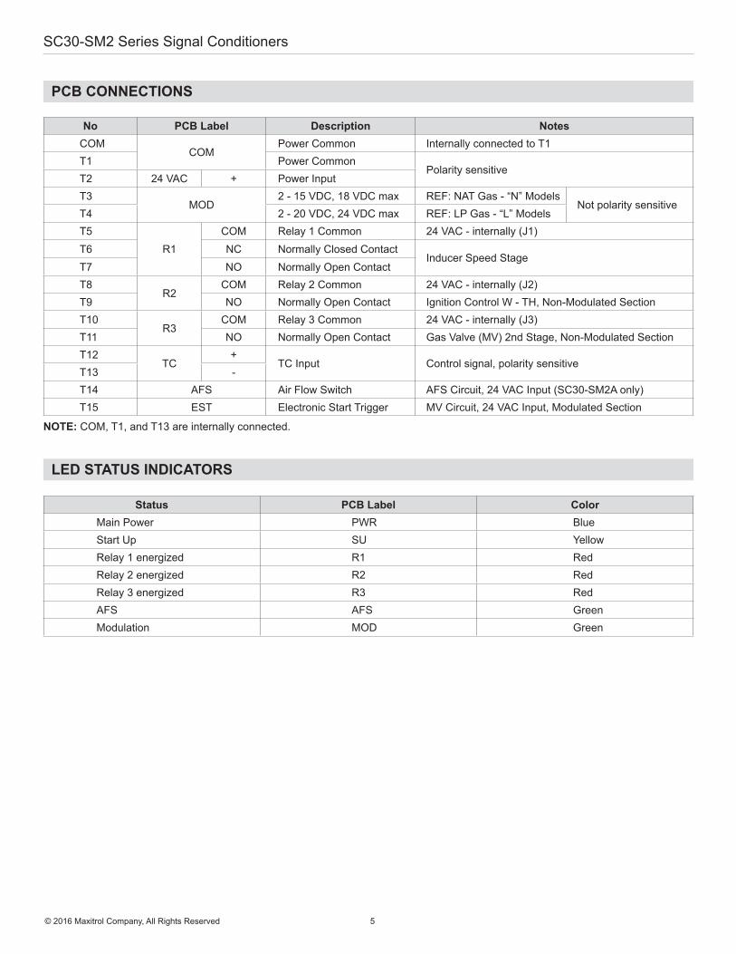
R1COM Relay 1 Common 24 VAC - internally (J1)
T6 NC Normally Closed ContactInducer Speed Stage
T7 NO Normally Open ContactT8
R2COM Relay 2 Common 24 VAC - internally (J2)
T9 NO Normally Open Contact Ignition Control W - TH, Non-Modulated SectionT10
R3COM Relay 3 Common 24 VAC - internally (J3)
T11 NO Normally Open Contact Gas Valve (MV) 2nd Stage, Non-Modulated SectionT12
TC+
TC Input Control signal, polarity sensitiveT13 -T14 AFS Air Flow Switch AFS Circuit, 24 VAC Input (SC30-SM2A only)T15 EST Electronic Start Trigger MV Circuit, 24 VAC Input, Modulated Section
NOTE: COM, T1, and T13 are internally connected.
Status PCB Label ColorMain Power PWR BlueStart Up SU YellowRelay 1 energized R1 RedRelay 2 energized R2 RedRelay 3 energized R3 RedAFS AFS GreenModulation MOD Green
5© 2016 Maxitrol Company, All Rights Reserved
SC30-SM2 Series Signal Conditioners
OPERATIONCALL FOR HEAT MODE
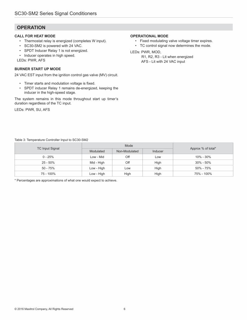
• Thermostat relay is energized (completes W input).• SC30-SM2 is powered with 24 VAC.• SPDT Inducer Relay 1 is not energized.• Inducer operates in high speed.
LEDs: PWR, AFS
BURNER START UP MODE24 VAC EST input from the ignition control gas valve (MV) circuit.
• Timer starts and modulation voltage is fixed.• SPDT inducer Relay 1 remains de-energized, keeping the
inducer in the high-speed stage.
The system remains in this mode throughout start up timer’s duration regardless of the TC input.
LEDs: PWR, SU, AFS
OPERATIONAL MODE• Fixed modulating valve voltage timer expires.• TC control signal now determines the mode.
LEDs: PWR, MOD, R1, R2, R3 - Lit when energized AFS - Lit with 24 VAC input
TC Input Signal Mode
Approx % of total*Modulated Non-Modulated Inducer
0 - 25% Low - Mid Off Low 10% - 30%
25 - 50% Mid - High Off High 30% - 50%
50 - 75% Low - High Low High 50% - 75%
75 - 100% Low - High High High 75% - 100%
Table 3: Temperature Controller Input to SC30-SM2
* Percentages are approximations of what one would expect to achieve.
6© 2016 Maxitrol Company, All Rights Reserved
SC30-SM2 Series Signal Conditioners
OPERATIONOPERATION: (see Table 3, page 6)
Stage I• TC Input: 0 - 25% (nominal).• Minimum to 30% of total rate.A
• Modulated Section is operational and modulating.Output range to M valve is approx. 2 - 7.5 VDC or 2 - 9.5 VDC.
• SPDT Relay 1 is energized.• Inducer operates in low-speed mode.
LEDs: PWR, MOD, R1
Stage II• TC Input: 25 - 50% (nominal).• 30% to 50% of total rate.A
• Modulated Section is operational and modulating.• Output range to M valve is approx. 7.5 - 15 VDC or
9.5 - 20 VDC.• TC Input voltage trigger is reached and SPDT Relay
1 is de-energized.• Inducer operates in high-speed mode.• SC30-SM2A: 24 VAC input to AFS or SW1-4 is “ON”.
LEDs: PWR, MOD, AFS
Stage III• TC Input: 50 - 75% (nominal).• 50% to 75% of total rate.A
• Modulated Section is operational and modulating.• Relay 2 is energized.• Output to mod valve to remain at 15 VDC or 20VDC
nominal for 5 - 30 seconds (adjustable).• Non-Modulated Section becomes operational and
operates in low stage (approx 50% of non-modulated section).
• Output range to M valve is 2B - 15VDC or 2B - 20 VDC.
LEDs: PWR, MOD, R2, AFS
Stage IV• TC input: 75 – 100% (nominal). • 75% to 100% of total rate.A
• Modulated Section is operational and modulating.• NO Relay 3 is energized. Gas valve switches to high
stage (100% of non-modulated section).• Output range to M valve is 2B- 15 VDC (18 VDC @ 10
VDC) or 2B- 20 VDC, (24 VDC @ 10 VDC).
LEDs: PWR, MOD, R2, R3, AFS
AFS (TERMINAL 14) SC30-SM2A Models
AFS LED• Lit when 24 VAC input is present or SW1-4 is “ON”. • Off when 24 VAC input is not present.
• Operating Condition #1 Relay 1 is energized and 24 VAC input is present or not present. Result: Normal operation of Stage I.
• Operating Condition #2 Relay 1 is de-energized and 24 VAC input is present. Result: Normal operation of all stages.
• Operating Condition #3 Relay 1 is de-energized and 24 VAC input is not present for duration greater than 3 seconds. Result:
- AFS Fault.- VDC output to valve is fixed to user-selected
voltage.- Relay 2 operation dependent on TC input. Relay 3
de-energized regardless of TC input. - VDC output remains fixed, even if the 24 VAC
signal is re-established, until reset.
• Resetting AFS Fault Perform one of the following:
- Cycle main power - Cycle EST input
- Energize Relay 1 with TC input
AFS Fault Override: Set SW1-4 to “ON”
7© 2016 Maxitrol Company, All Rights Reserved
A - Percentages are approximations of what one would expect to achieve.B - Adjustable low.