64
90-892133 JULY 2003 2003 Mercury Marine Operation Manual System View Version 3.XX SC5000

90-892133 JULY 20032003 Mercury Marine
Operation Manual
System ViewVersion 3.XX
SC5000
INTRODUCTION 1GETTING STARTED 2PROPULSION 3VESSEL 4NAVIGATION/FUEL 5SETTINGS 6SYSTEMS 7INSTALLATION 8
A to Z INDEX 9
90-892133 JULY 20032003 Mercury Marine
CONTENTS
Section 1 - IntroductionSection 2 - Getting Started
• Starting Up the System View• Display Screens
Section 3 - Propulsion• Enginr RPM and Speed• Engine RPM Synchronizer – Twin Engines• Engine Data Screen (s)• Trim Position• Troll Control• Peak Speed at RPM
Section 4 - Vessel• Steering Position• Fuel, Water, and Waste Tank Level Status• Vessel Status Data
Section 5 - Navigation/Fuel• Vessel Course• Next Waypoint• Trip History• Estimated Fuel Range• Depth• Air Temperature• Seawater Temperature
Section 6 - Settings• Contrast/Lighting/Clock• Units/Language/Offsets• Home Page Data• Sensors• Preferences• Favorites/Page Status
Section 7 - Systems• System Calibration• Maintenance Log• Active Alarms• Alarm History
Section 8 - Installation• System View Installation• Wiring Information• Installation Configurations
Section 9 - Index
1INTRODUCTION
90-892133 JULY 2003 Page 1-1
IntroductionThe SC5000 System View Display is a comprehensive boat information center. SystemView allows the boat operator to receive a wealth of critical operational information, dis-played clearly and instantly at the helm on the LCD display. The System View continuous-ly monitors and reports information ranging from basic operating data to detailed vesselenvironment information. System View covers water temperature and depth, engine trimstatus, boat speed, steering angle, system preventive maintenance reminders and sys-tems diagnostics. System View also can be fully integrated with the boat’s GPS, ifequipped, to provide up to the minute course, speed, and fuel-to-destination information.
System View Displays Detailed Information in These Important Categories:NOTE: The detailed information listed which is standard on some models may be option-al on others, or may not be available on some models based on engine and system con-figuration.
Propulsion Information Section 3
• Engine RPM combined with boat speed
• Twin engine synchronizer display
• Peak boat speed in conjunction with peak engine RPM
• Engine data screen(s)
• Troll control
• Trim position
Vessel Information Section 4
• Steering angle display
• Fuel tank, oil tank, water tank, and waste water tank level display
• Vessel status
Navigation and Fuel Section 5
• Direction to target waypoint information shows present course and current speed ona graphic compass rose
• Shows distance, time, speed, and fuel to next waypoint
• Resettable trip history shows miles per hour, miles per gallon, elapsed drive time, andamount of fuel consumed on current trip
• Water depth with depth history graph
• Sea water temperature with temperature history graph
Alarm, Diagnostic, and Maintenance Information Section 7
• Displays alarms and helpful information concerning alarm causes
• Automatic maintenance reminders and log recorder for periodic propulsion maintenance

INTRODUCTION
Page 1-2 90-892133 JULY 2003
Keypad UsageThe System View uses icons and text selection to perform all the functions.
ArrowTrackpad
Home
Select
The ARROW TRACKPAD controls up and down and side to side movementfor on-screen function prompts.
The SELECT key is used to select screen options and confirm data entry.
The HOME (power) key has two different functions: 1.) Pressing the HOME key will return the System View display back to thehome page directory. 2.) The HOME key can be used to power-up or turn off the System View. Pressing and holding in the HOME key for 3 seconds with key switch turnedoff will power-up or turn off the System View.

INTRODUCTION
90-892133 JULY 2003 Page 1-3
Keypad UsageREMOTE LOCATION – ELECTRONIC THROTTLE AND SHIFT MODELS
1
2
3
Console Remote Control – Single
Panel Remote Control
4
7
654
1
2
3
Console Remote Control – Dual
Console Remote Control
1. Arrow Trackpad – Can be used to operate the up and down and side to side movement forSystem View on-screen function promps.
2. Select Key – Can be used to select System View on-screen options and confirm dataentries. Pressing the Select switch for 2 seconds will return the System View displayback to the Home page.
3. Neutral LIGHT – The neutral light is illuminated when the engine is in neutral gear posi-tion. The light blinks when engine is in warm up mode.
4. Active LIGHT – The active light is illuminated to show the remote control is active andready for use
5. Sync LIGHT – The sync light is illuminated when the auto synchronizing feature is en-gaged. The auto synchronizing will automatically engage when both engines are above900 RPM for 2 seconds and the throttles are within 10% of each other. The auto synchro-nizing will operate up to 95% throttle opening. The auto automatically engages as soonas the engines meet these conditions.
Panel Remote Control
6. Scroll Key – Can be used to scroll through System View displays on the display screen.
7. Select Key – Can be used to select System View on-screen options. Pressing the Selectswitch for 2 seconds will return the System View display back to the Home page.

2
GETTING STARTED
90-892133 JULY 2003 Page 2-1
GETTING STARTEDSection 2
Table of Contents
Starting up the System View 2-2. . . . . . . . . . . . . . . . . . . . . . . . . . . . . . . . . . . . . . . . . . . . . . . . . Display Screens 2-2. . . . . . . . . . . . . . . . . . . . . . . . . . . . . . . . . . . . . . . . . . . . . . . . . . . . . . . . . . . .
Start-up Screens 2-2. . . . . . . . . . . . . . . . . . . . . . . . . . . . . . . . . . . . . . . . . . . . . . . . . . . . . . . . Home Page Screen 2-3. . . . . . . . . . . . . . . . . . . . . . . . . . . . . . . . . . . . . . . . . . . . . . . . . . . . . . Data Display Screens 2-5. . . . . . . . . . . . . . . . . . . . . . . . . . . . . . . . . . . . . . . . . . . . . . . . . . . . Alarm Message Screens 2-9. . . . . . . . . . . . . . . . . . . . . . . . . . . . . . . . . . . . . . . . . . . . . . . . . .
GETTING STARTED
Page 2-2 90-892133 JULY 2003
Starting Up the System View
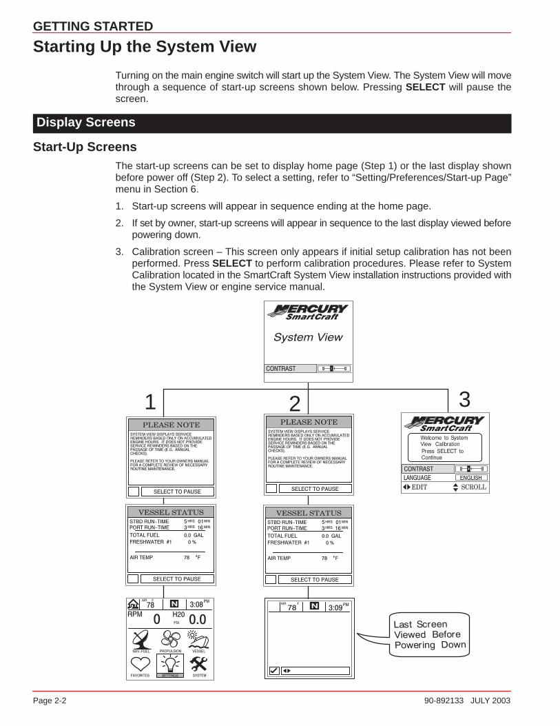
Turning on the main engine switch will start up the System View. The System View will movethrough a sequence of start-up screens shown below. Pressing SELECT will pause thescreen.
Display Screens
Start-Up ScreensThe start-up screens can be set to display home page (Step 1) or the last display shownbefore power off (Step 2). To select a setting, refer to “Setting/Preferences/Start-up Page”menu in Section 6.
1. Start-up screens will appear in sequence ending at the home page.
2. If set by owner, start-up screens will appear in sequence to the last display viewed beforepowering down.
3. Calibration screen – This screen only appears if initial setup calibration has not beenperformed. Press SELECT to perform calibration procedures. Please refer to SystemCalibration located in the SmartCraft System View installation instructions provided withthe System View or engine service manual.
1 2 3
GETTING STARTED
90-892133 JULY 2003 Page 2-3
Display Screens
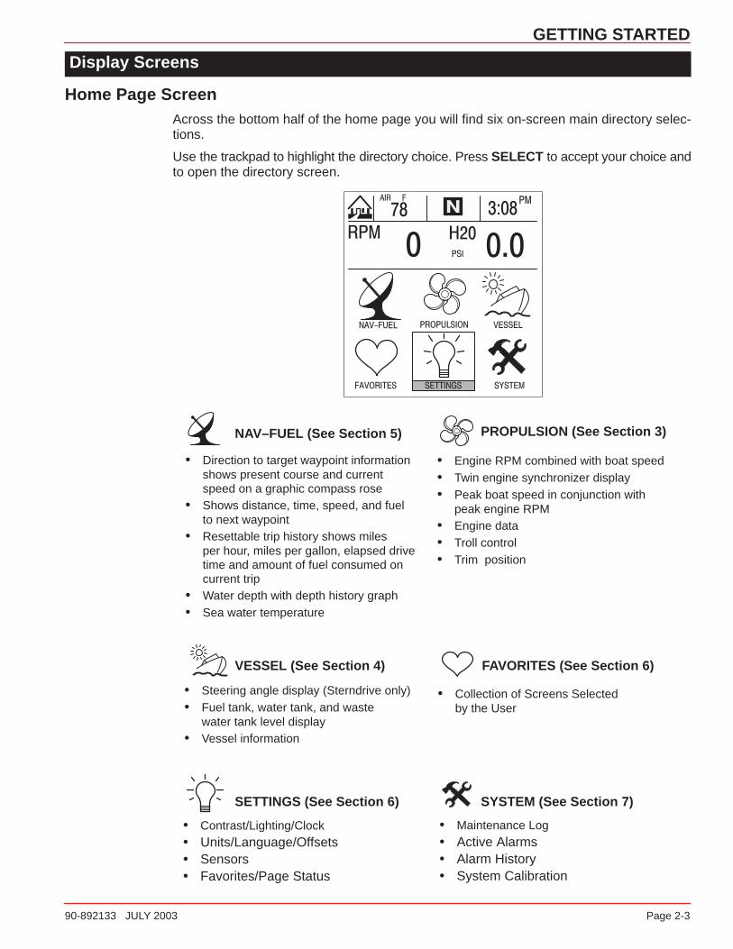
Home Page ScreenAcross the bottom half of the home page you will find six on-screen main directory selec-tions.
Use the trackpad to highlight the directory choice. Press SELECT to accept your choice andto open the directory screen.
• Engine RPM combined with boat speed• Twin engine synchronizer display• Peak boat speed in conjunction with
peak engine RPM• Engine data• Troll control• Trim position
• Steering angle display (Sterndrive only)• Fuel tank, water tank, and waste
water tank level display• Vessel information
• Direction to target waypoint information shows present course and current speed on a graphic compass rose
• Shows distance, time, speed, and fuel to next waypoint
• Resettable trip history shows miles per hour, miles per gallon, elapsed drive time and amount of fuel consumed on current trip
• Water depth with depth history graph• Sea water temperature
• Collection of Screens Selectedby the User
• Maintenance Log• Active Alarms• Alarm History• System Calibration
• Contrast/Lighting/Clock• Units/Language/Offsets• Sensors• Favorites/Page Status
NAV–FUEL (See Section 5)
VESSEL (See Section 4)
SETTINGS (See Section 6)
PROPULSION (See Section 3)
FAVORITES (See Section 6)
SYSTEM (See Section 7)
GETTING STARTED
Page 2-4 90-892133 JULY 2003
Display Screens
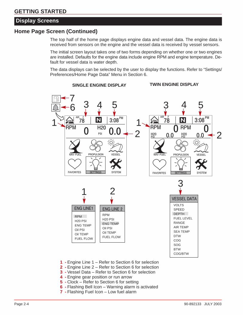
Home Page Screen (Continued)The top half of the home page displays engine data and vessel data. The engine data isreceived from sensors on the engine and the vessel data is received by vessel sensors.
The initial screen layout takes one of two forms depending on whether one or two enginesare installed. Defaults for the engine data include engine RPM and engine temperature. De-fault for vessel data is water depth.
The data displays can be selected by the user to display the functions. Refer to “Settings/Preferences/Home Page Data” Menu in Section 6.
SINGLE ENGINE DISPLAY TWIN ENGINE DISPLAY
2
3 45
211
34 5
RPMH20 PSIENG TEMPOil PSIOil TEMPFUEL FLOW
VOLTSSPEEDDEPTHFUEL LEVELRANGEAIR TEMPSEA TEMPDTWCOGSOGBTWCOG/BTW
23
1
6
RPMH20 PSIENG TEMPOil PSIOil TEMPFUEL FLOW
7
1 - Engine Line 1 – Refer to Section 6 for selection2 - Engine Line 2 – Refer to Section 6 for selection3 - Vessel Data – Refer to Section 6 for selection4 - Engine gear position or run arrow5 - Clock – Refer to Section 6 for setting6 - Flashing Bell Icon – Warning alarm is activated7 - Flashing Fuel Icon – Low fuel alarm
GETTING STARTED
90-892133 JULY 2003 Page 2-5
Display Screens
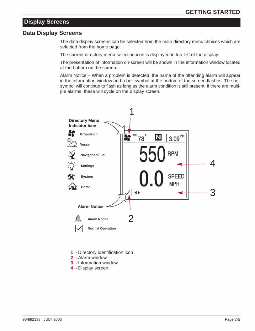
Data Display ScreensThe data display screens can be selected from the main directory menu choices which areselected from the home page.
The current directory menu selection icon is displayed in top-left of the display.
The presentation of information on-screen will be shown in the information window locatedat the bottom on the screen.
Alarm Notice – When a problem is detected, the name of the offending alarm will appearin the information window and a bell symbol at the bottom of the screen flashes. The bellsymbol will continue to flash as long as the alarm condition is still present. If there are multi-ple alarms, these will cycle on the display screen.
Propulsion
Vessel
Navigation/Fuel
Settings
System
Directory MenuIndicator Icon
Alarm Notice
Alarm Notice
Normal Operation
2
1
3
4
Home
1 - Directory identification icon2 - Alarm window3 - Information window4 - Display screen

GETTING STARTED
Page 2-6 90-892133 JULY 2003
Display Screens
Data Display Screens
Glossary
Data Screen Directory Location
Engine Data Screen(s)Engine data screen(s) is a group of displaysshowing various engine data.
Engine RPM and SpeedDisplays engine RPM and boat speed.
Engine RPM SynchronizerTwin Engines – Displays the difference in en-gine speed (RPM) between the port and star-board engines
Peak Speed at RPMThis screen records the top speed the boatreached and associated engine RPM as mea-sured since the last reset.
Trim PositionDisplay indicates the propulsion unit positionachieved by setting trim and trailer position.
Troll ControlMaintain a trolling speed without using thethrottle.

GETTING STARTED
90-892133 JULY 2003 Page 2-7
Display Screens
Data Display Screens
Glossary
Data Screen Directory Location
Steering PositionDisplays steering position in degrees.
Tank StatusShows level of the vessel’s tanks.
Tank LevelsDisplays the level of each tank.
Vessel StatusDisplays engine run timeTotal fuel remainingAdditional tank levelsAir temperature
DepthDisplays the depth of water.
Trip History LogDisplays average fuel economy, average boatspeed, total drive time, along with a corre-sponding distance traveled and fuel used.

GETTING STARTED
Page 2-8 90-892133 JULY 2003
Display Screens
Data Display Screens
Glossary
Data Screen Directory Location
Depth Plot LineDisplays a plot line of depth vs. time as re-corded over the last 16 seconds.
EnvironmentDisplays speed, depth, air temperature, andsea water temperature.
Estimated Fuel RangeDisplays estimated range and fuel remaining,as well as current total fuel flow.
Navigation Screen 1Displays a compass and shows direction to atargeted waypoint.
Navigation Screen 2Displays navigating data to a waypoint.
Seawater Temperature Plot LIneDisplays a plot line of seawater temperaturevs. time as recorded over the last 80 seconds.Also displays the current water temperature.

GETTING STARTED
90-892133 JULY 2003 Page 2-9
Display Screens
Alarm Message ScreensWhen a problem is detected, the System View will alert the operator. Use the following stepsto determine the cause of the problem:
1. A pop-up screen will appear displaying an alarm message. If there are multiple alarms,the display will show the last alarm activated.
2. Press SELECT to clear the pop-up screen(s) and return back to the display screen thatwas being viewed. Bell icon will now be flashing and alarm message will be displayedon the bottom of the screen.
3. A number of different problems may be grouped together under one alarm message.To determine the exact cause of the problem, return back to the home page and accessthe SYSTEM directory. The SYSTEM directory will show the active alarm(s) causing theproblem.
4. Refer to the “Active Alarms” in Section 7 or the Engine Operation, Maintenance Manualfor further explanation of the problem and the correct action to take.
If the problem can cause immediate engine damage, the engine guardian system will respondto the problem by limiting engine power.
2
1
3
PROPULSION
90-892133 JULY 2003 Page 3-1
PROPULSIONSection 3
Table of Contents
Propulsion Information 3-2. . . . . . . . . . . . . . . . . . . . . . . . . . . . . . . . . . . . . . . . . . . . . . . . . . . . . . Entering the Propulsion Directory 3-2. . . . . . . . . . . . . . . . . . . . . . . . . . . . . . . . . . . . . . . . . . . . . Propulsion Data Screens 3-3. . . . . . . . . . . . . . . . . . . . . . . . . . . . . . . . . . . . . . . . . . . . . . . . . . . .
Engine RPM/Speed 3-3. . . . . . . . . . . . . . . . . . . . . . . . . . . . . . . . . . . . . . . . . . . . . . . . . . . . . . Peak Speed at RPM 3-3. . . . . . . . . . . . . . . . . . . . . . . . . . . . . . . . . . . . . . . . . . . . . . . . . . . . . Engine RPM Synchronizer – Twin Engines 3-4. . . . . . . . . . . . . . . . . . . . . . . . . . . . . . . . . . Engine Data Screens 3-4. . . . . . . . . . . . . . . . . . . . . . . . . . . . . . . . . . . . . . . . . . . . . . . . . . . . Trim Position 3-5. . . . . . . . . . . . . . . . . . . . . . . . . . . . . . . . . . . . . . . . . . . . . . . . . . . . . . . . . . . Troll Control 3-6. . . . . . . . . . . . . . . . . . . . . . . . . . . . . . . . . . . . . . . . . . . . . . . . . . . . . . . . . . . . .
3

PROPULSION
Page 3-2 90-892133 JULY 2003
Propulsion Information
This Section will give a complete description of the display screens in the PROPULSIONdirectory of the System View.
Some of the propulsion functions are:
• Troll control
• Engine RPM combined with boat speed
• Twin engine synchronizer display
• Peak boat speed in conjunction with peak engine RPM
• Trim position
• Engine data screen(s)
Entering the Propulsion Directory
To access the PROPULSION directory, use the trackpad to highlight the PROPULSION di-rectory from the menu choice. Press SELECT to accept and to open the directory.

PROPULSION
90-892133 JULY 2003 Page 3-3
Propulsion Data Screens
Engine RPM/SpeedThis screen displays engine speed (RPM) and boat speed.
SINGLE ENGINE TWIN ENGINE
1
1 - Speed Sensors – This window shows the sensor that is currently sending thespeed signal. The speed sensor is automatically selected based on what sen-sors are available.
Peak Speed at RPM
This screen records the top speed the boat reached and associated engine RPM as mea-sured since the last reset.
To Reset the Peak Speed and corresponding RPM, press and hold the SELECT button mo-mentarily.
SINGLE ENGINE TWIN ENGINE
1
1 - Speed Sensors – This window shows the sensor that is currently sending thespeed signal. The speed sensor is automatically displayed based on what sen-sors are available.

PROPULSION
Page 3-4 90-892133 JULY 2003
Propulsion Data Screens
Engine RPM Synchronizer – Twin EngineThis screen displays the difference in engine speed (RPM) between the port and starboard en-gines. Allows throttle adjustments to keep each engine running uniformly.
StarboardEngine
Port Engine
Engine Data Screen(s)Engine data screen(s) is a group of displays showing various engine data.
NOTE: Not all screens listed may be available for your type of engine.
1. ENGINE TEMP (Temperature) – Displays engine temperature. The temperature willvary with air temperature, water temperature and operating conditions.
2. H20 PRESSURE (Water) – Displays engine water pressure when engine is running.
3. BATTERY – Displays battery voltage level (condition) of battery.
4. FUEL FLOW – Displays current estimated engine fuel consumption in U.S. Gallons perhour (Gal/hr) or Liters per hours (Ltr/hr).
5. OIL PRESSURE – Displays engine oil pressure when the engine is running. The oilpressure may vary with engine speed, outside temperature and oil viscosity. While theengine is warming up, the oil pressure will be higher than when the engine is at normaloperating temperature.
41
52
3

PROPULSION
90-892133 JULY 2003 Page 3-5
Propulsion Data Screens
Trim PositionDisplay indicates the propulsion unit position achieved by setting trim and trailer position.
SINGLE ENGINE
TWIN ENGINE
PROPULSION
Page 3-6 90-892133 JULY 2003
Propulsion Data Screens
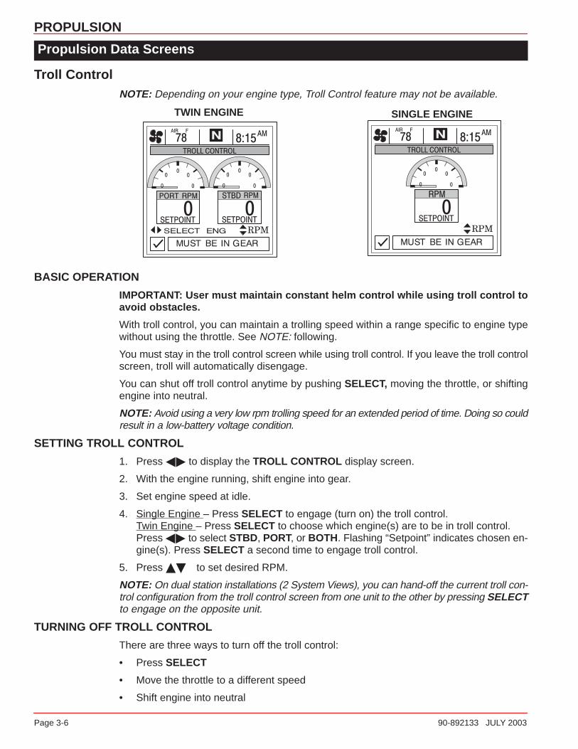
Troll ControlNOTE: Depending on your engine type, Troll Control feature may not be available.
SINGLE ENGINETWIN ENGINE
BASIC OPERATION
IMPORTANT: User must maintain constant helm control while using troll control toavoid obstacles.
With troll control, you can maintain a trolling speed within a range specific to engine typewithout using the throttle. See NOTE: following.
You must stay in the troll control screen while using troll control. If you leave the troll controlscreen, troll will automatically disengage.
You can shut off troll control anytime by pushing SELECT, moving the throttle, or shiftingengine into neutral.
NOTE: Avoid using a very low rpm trolling speed for an extended period of time. Doing so couldresult in a low-battery voltage condition.
SETTING TROLL CONTROL
1. Press �� to display the TROLL CONTROL display screen.
2. With the engine running, shift engine into gear.
3. Set engine speed at idle.
4. Single Engine – Press SELECT to engage (turn on) the troll control.Twin Engine – Press SELECT to choose which engine(s) are to be in troll control. Press �� to select STBD, PORT, or BOTH. Flashing “Setpoint” indicates chosen en-gine(s). Press SELECT a second time to engage troll control.
5. Press �� to set desired RPM.
NOTE: On dual station installations (2 System Views), you can hand-off the current troll con-trol configuration from the troll control screen from one unit to the other by pressing SELECTto engage on the opposite unit.
TURNING OFF TROLL CONTROL
There are three ways to turn off the troll control:
• Press SELECT
• Move the throttle to a different speed
• Shift engine into neutral
4
VESSEL
90-892133 JULY 2003 Page 4-1
VESSELSection 4
Table of Contents
Vessel Information 4-2. . . . . . . . . . . . . . . . . . . . . . . . . . . . . . . . . . . . . . . . . . . . . . . . . . . . . . . . . . Entering the Vessel Directory 4-2. . . . . . . . . . . . . . . . . . . . . . . . . . . . . . . . . . . . . . . . . . . . . . . . Vessel Data Screens 4-3. . . . . . . . . . . . . . . . . . . . . . . . . . . . . . . . . . . . . . . . . . . . . . . . . . . . . . .
Steering Position 4-3. . . . . . . . . . . . . . . . . . . . . . . . . . . . . . . . . . . . . . . . . . . . . . . . . . . . . . . . Tank Status 4-3. . . . . . . . . . . . . . . . . . . . . . . . . . . . . . . . . . . . . . . . . . . . . . . . . . . . . . . . . . . . . Fuel Tanks 4-4. . . . . . . . . . . . . . . . . . . . . . . . . . . . . . . . . . . . . . . . . . . . . . . . . . . . . . . . . . . . . . Water and Waste Tanks 4-4. . . . . . . . . . . . . . . . . . . . . . . . . . . . . . . . . . . . . . . . . . . . . . . . . . Vessel Status 4-5. . . . . . . . . . . . . . . . . . . . . . . . . . . . . . . . . . . . . . . . . . . . . . . . . . . . . . . . . . .

VESSEL
Page 4-2 90-892133 JULY 2003
Vessel Information
This Section will give a complete description of the display screens in the VESSEL directoryof the System View.
Some of the vessel functions are:
• Steering angle position
• Tank status for fuel, oil, waste, and water
• Vessel status
Entering the Vessel Directory
To access the VESSEL directory, use the trackpad to highlight the VESSEL directory fromthe menu choice. Press SELECT to accept and to open the directory.

VESSEL
90-892133 JULY 2003 Page 4-3
Vessel Data Screens
Steering PositionThis screen displays steering position in degrees.
NOTE: Depending on your type of engine, this feature may not be available.
NOTE: If steering angle position is opposite the direction that it should be, it can be reversedso it is displayed properly. Refer to “Settings/Sensors/Invert Steering” Menu in Section 6.
Tank StatusNOTE: If your vessel installation includes tank level sensors, System View will display full-ness level that is provided by the sensors.
The display screens show the level of the vessels tanks. The bar gauges and digital read-outs indicate the level of fullness of each tank.
SCREEN 1 SCREEN 2

VESSEL
Page 4-4 90-892133 JULY 2003
Vessel Data Screens
Fuel TanksDisplays the level of each tank.
Water and Waste TanksDisplays the level of each tank.

VESSEL
90-892133 JULY 2003 Page 4-5
Vessel Data Screens
Vessel StatusDisplays the current vessel information.
1. Displays run time in hours.
2. Displays the total fuel remaining.
3. Displays additional tank levels. Fresh water and waste water if connected.
4. Displays air temperature at sensor.
1234

5
NAVIGATION/FUEL
90-892133 JULY 2003 Page 5-1
NAVIGATION/FUELSection 5
Table of Contents
Navigation/Fuel Information 5-2. . . . . . . . . . . . . . . . . . . . . . . . . . . . . . . . . . . . . . . . . . . . . . . . . . Entering the Navigation/Fuel Directory 5-2. . . . . . . . . . . . . . . . . . . . . . . . . . . . . . . . . . . . . . . . Navigation/Fuel Data Screens 5-3. . . . . . . . . . . . . . . . . . . . . . . . . . . . . . . . . . . . . . . . . . . . . . .
Vessel Course – Course Up 5-3. . . . . . . . . . . . . . . . . . . . . . . . . . . . . . . . . . . . . . . . . . . . . . . Next Waypoint Data 5-4. . . . . . . . . . . . . . . . . . . . . . . . . . . . . . . . . . . . . . . . . . . . . . . . . . . . . . Trip History Log 5-4. . . . . . . . . . . . . . . . . . . . . . . . . . . . . . . . . . . . . . . . . . . . . . . . . . . . . . . . . Depth 5-5. . . . . . . . . . . . . . . . . . . . . . . . . . . . . . . . . . . . . . . . . . . . . . . . . . . . . . . . . . . . . . . . . . Depth Plot Line 5-5. . . . . . . . . . . . . . . . . . . . . . . . . . . . . . . . . . . . . . . . . . . . . . . . . . . . . . . . . . Environment – Speed, Depth, Air and Sea Water Temperature 5-6. . . . . . . . . . . . . . . . Seawater Temperature Plot 5-6. . . . . . . . . . . . . . . . . . . . . . . . . . . . . . . . . . . . . . . . . . . . . . . Estimated Fuel Range 5-7. . . . . . . . . . . . . . . . . . . . . . . . . . . . . . . . . . . . . . . . . . . . . . . . . . . .

NAVIGATION/FUEL
Page 5-2 90-892133 JULY 2003
Navigation/Fuel Information
This Section will give a complete description of the display screens in the NAV–FUEL direc-tory of the System View.
Some of the navigation/fuel functions are:
• Navigation screens• Next waypoint data• Trip history log• Depth• Depth plot line• Depth, speed, air temperature, and water temperature• Seawater plot line• Estimated fuel range
Entering the Navigation/Fuel Directory
To access the NAV–FUEL directory, use the trackpad to highlight the NAV/FUEL directoryfrom the menu choice. Press SELECT to accept and to open the directory.

NAVIGATION/FUEL
90-892133 JULY 2003 Page 5-3
Navigation/Fuel Data Screens
Navigation ScreensIMPORTANT: This device is intended as a navigation aid and should not take theplace of paper charts. A careful navigator never relies on one method to obtain posi-tion information.
NOTE: For use of the navigation screens, your vessel must include a GPS receiver withNMEA 0183 V1.5 or V2.0+ output and be connected to the System View.
The System View features two different navigation screens: Vessel Course and Next Way-point Data. Next Waypoint Data provides course guidance to a destination waypoint, if pro-grammed into your GPS navigation electronics.
SCREEN # 1 – VESSEL COURSE – COURSE UP
This vessel course – course up screen has a rotating compass ring that not only shows yourdirection of travel, but also the direction to a targeted waypoint. When you are not navigatingto a waypoint, the compass will show your direction of travel. The boat pointer in the centerof the compass ring shows current direction.
When a waypoint is set using a separate GPS unit, an X mark will appear on the compassring. This X mark will indicate your waypoint. For instance, if the X mark lines up with thecenter of the boat pointer, you are going directly to the waypoint. If the boat pointer does notline up with the X mark, steer toward the X mark until it lines up with the center of the boatpointer– then continue in this direction until you reach your current target waypoint.
The middle of the compass shows the current cross track error (XTE). This is the distanceyou are off-course relative to the desired course.
Anytime a compatible GPS is connected, the current Speed Over Ground (SOG) as well asthe Course Over Ground (COG) are displayed on the screen.
1
23
45
6
7
1 - Compass ring2 - Boat pointer3 - X – Mark (Gives the Direction to Steer)4 - Cross track error5 - Course over ground (COG)6 - Speed over ground (SOG)7 - GPS Heading – True or Magnetic – Refer to “Settings/Preference/GPS Head-
ing” Menu in Section 6

NAVIGATION/FUEL
Page 5-4 90-892133 JULY 2003
Navigation/Fuel Data Screens
Navigation ScreensSCREEN # 2 – NEXT WAYPOINT DATA
When navigating to a waypoint, this screen will give you the following navigation informa-tion:
1. DIST TO GO – Remaining distance to the next waypoint.
2. TIME TO GO – Is the time that it will take to reach your waypoint at your present speed.
3. FUEL TO GO – Is the fuel it will take to get to your waypoint.
4. SPD TO WPT – Is the speed you are making towards your waypoint.
1 2
3 4
Trip History LogThis screen tracks your boat’s progress since last reset. Displays average fuel economy,average boat speed, total drive time, along with a corresponding distance traveled and fuelused.
To Reset trip history log, press and hold down SELECT for 5 seconds.
1. Displays the average distance per U.S. gallon or liter of fuel since the unit was last reset.
2. Displays the average speed of the boat since the unit was last reset.
3. Displays the time in hours of the engine usage since the unit was last reset.
4. Displays the total distance traveled since the unit was last reset.
5. Displays the total fuel used since the unit was last reset.
1
2
345

NAVIGATION/FUEL
90-892133 JULY 2003 Page 5-5
Navigation/Fuel Data Screens
DepthDEPTH displays the depth of water.
NOTE: To set depth and shallow water alarm levels, refer to “Settings/Sensors” Menu inSection 6.
Depth Plot LineDEPTH PLOT displays a plot of depth vs. time as recorded over the last 16 seconds.
NOTE: To set depth and shallow water alarm levels, refer to “Settings/Sensors” Menu inSection 6.
1. Displays depth plot line.
2. Displays current water depth.
3. Displays low water alarm setting.
1
2 3
NAVIGATION/FUEL
Page 5-6 90-892133 JULY 2003
Navigation/Fuel Data Screens
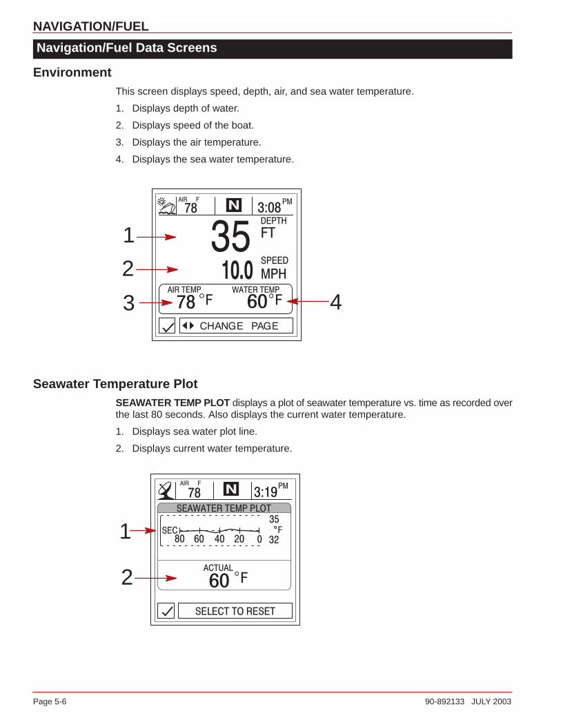
EnvironmentThis screen displays speed, depth, air, and sea water temperature.
1. Displays depth of water.
2. Displays speed of the boat.
3. Displays the air temperature.
4. Displays the sea water temperature.
1
2
3 4
Seawater Temperature PlotSEAWATER TEMP PLOT displays a plot of seawater temperature vs. time as recorded overthe last 80 seconds. Also displays the current water temperature.
1. Displays sea water plot line.
2. Displays current water temperature.
1
2

NAVIGATION/FUEL
90-892133 JULY 2003 Page 5-7
Navigation/Fuel Data Screens
Estimated Fuel RangeESTIMATED FUEL RANGE displays estimated range and fuel remaining, as well as currentfuel flow.
1. The estimated fuel range is based on boat speed, fuel consumption, and fuel remaining inthe tank. The number displayed indicates an estimate of the distance you can travel on theremaining fuel. Speed input required (paddle wheel, pitot pressure, or GPS).
2. Displays the current vessel fuel consumption in U.S. gallons per hour or liters per hour.
3. Displays amount of fuel remaining.
1
2 3

6
SETTINGS
90-892133 JULY 2003 Page 6-1
SETTINGSSection 6
Table of Contents
Settings Information 6-2. . . . . . . . . . . . . . . . . . . . . . . . . . . . . . . . . . . . . . . . . . . . . . . . . . . . . . . . Entering the Settings Directory 6-2. . . . . . . . . . . . . . . . . . . . . . . . . . . . . . . . . . . . . . . . . . . . . . . Settings Directory 6-2. . . . . . . . . . . . . . . . . . . . . . . . . . . . . . . . . . . . . . . . . . . . . . . . . . . . . . . . . . Settings Options 6-3. . . . . . . . . . . . . . . . . . . . . . . . . . . . . . . . . . . . . . . . . . . . . . . . . . . . . . . . . . .
Contrast/Lighting/Clock 6-3. . . . . . . . . . . . . . . . . . . . . . . . . . . . . . . . . . . . . . . . . . . . . . . . . . . Units/Language/Offsets 6-4. . . . . . . . . . . . . . . . . . . . . . . . . . . . . . . . . . . . . . . . . . . . . . . . . . Home Page Data 6-5. . . . . . . . . . . . . . . . . . . . . . . . . . . . . . . . . . . . . . . . . . . . . . . . . . . . . . . . Sensors 6-6. . . . . . . . . . . . . . . . . . . . . . . . . . . . . . . . . . . . . . . . . . . . . . . . . . . . . . . . . . . . . . . . Preferences 6-7. . . . . . . . . . . . . . . . . . . . . . . . . . . . . . . . . . . . . . . . . . . . . . . . . . . . . . . . . . . . . Favorites/Page Status 6-8. . . . . . . . . . . . . . . . . . . . . . . . . . . . . . . . . . . . . . . . . . . . . . . . . . . .

SETTINGS
Page 6-2 90-892133 JULY 2003
Settings Information
This Section will give a complete description of the Settings screens in the SETTINGS direc-tory of the System View.
In this Section you can configure your System View to display the information the way youprefer.
Some of the Settings functions are:
• Customizing the home page data• Contrast/Lighting/Clock• Units/Language/Offsets• Sensor settings• Favorites/Page status• Setting your preferences
Entering the Settings Directory
To access the SETTINGS directory, use the trackpad to highlight the SETTINGS directoryfrom the menu choice. Press SELECT to accept and to open the directory screen.
Settings Directory
Settings Directory Screen

SETTINGS
90-892133 JULY 2003 Page 6-3
Settings Options
Contrast/Lighting/ClockTo adjust a setting:
1. Press �� to highlight the desired menu selection.
2. Press �� to edit the menu box.
3. Press SELECT to accept settings.
CONTRAST – Provides a slide bar to adjust the display screen contrast to compensate for changes intemperature or lighting conditions.
BRIGHTNESS – Provides a slide bar to adjust the display screen lighting level.
TWILIGHT – The twilight setting is a light sensor setting that adjusts the amount of light needed to au-tomatically turn on the System View backlighting and the System Link gauge lighting. You can manuallycontrol when the backlighting turns on by adjusting the slide bar.
TIME – If no GPS is connected, press the horizontal arrows to the set the current time. If GPS is con-nected, follow time zone setting below.
TIME ZONE – Time zone setting is how many hours you are behind or ahead of Greenwich Mean Time(GMT). The chart below gives approximate GMT time zone settings for various longitudinal zones. Addone hour to the setting for daylight savings time.
CLOCK MODE – Select 12 hour or 24 hour clock set.
Longitudinal Zone Time Zone
Setting
DayLIght
Saving Time
Zone Setting
Longitudinal Zone Time Zone
Setting
DayLIght
Saving Time
Zone Setting
W180.0° to W172.5° –12 –11 E007.5° to E022.5° +1 +2
W172.5° to W157.5° –11 –10 E022.5° to E037.5° +2 +3
W157.5° to W142.5° –10 –9 E037.5° to E052.5° +3 +4
W142.5° to W127.5° –9 –8 E052.5° to E067.5° +4 +5
W127.5° to W112.5° (Pacific Standard Time) –8 –7 E067.5° to E083.5° +5 +6
W112.5° to W097.5° (Mountain Standard Time) –7 –6 E082.5° to E097.5° +6 +7
W097.5° to W082.5° (Central Standard Time) –6 –5 E097.5° to E112.5° +7 +8
W082.5° to W067.5° (Eastern Standard Time) –5 –4 E112.5° to E127.5° +8 +9
W067.5° to W052.5° –4 –3 E127.5° to E142.5° +9 +10
W052.5° to W037.5° –3 –2 E142.5° to E157.5° +10 +11
W037.5° to W022.5° –2 –1 E157.5° to E172.5° +11 +12
W022.5° to W007.5° –1 0 E172.5° to E180.0° +12 +13
W007.5° to E007.5° 0 +1

SETTINGS
Page 6-4 90-892133 JULY 2003
Settings Options
Units/Language/OffsetsTo adjust a setting:
1. Press �� to highlight the desired menu selection.
2. Press �� to edit the menu box.
3. Press SELECT to accept settings.
UNITS ENG – Lets you select English or metric format for unit measurements.
UNITS SPD – Lets you select the units at which speed is displayed. You may select from MPH (MilesPer Hour), KM/H (Kilometers Per Hour) or Knots.
LANGUAGE – System View displays only English at this time.
DEPTH OFFSET TO – Normally, this unit measures water depth from the face of the transducer (sen-sor). Since the transducer is below the water, this distance is not the exact water depth. You canchange the depth reading using this depth offset feature. You have three depth offsets selections:1. SENSOR – Will measure water depth from the face of the transducer. No setting to depth offset is necessary.2. WATERLINE – Will give water depth from the surface of the water. You will need to change the depth offset setting below. Measure the distance between the face of the transducer and the water line. Add this measurement into depth offset menu box below.3. KEEL – Will give water depth from the keel of the boat. You will need to change the depth offset setting below. Measure the distance between the transducer and the lowest part of the boat. Place this measurement into depth offset menu box below. This offset will be a negative value.
DEPTH OFFSET – Activate the depth offset feature by adding the measurement taken above to com-pensate for waterline or keel offset.
SEA TEMP OFFSET – The sea water temperature sensor can be calibrated to match actual sea watertemperature. Calculate the difference in degrees that the sea water temperature is off and enter it intothe menu window.
STEERING OFFSET – The steering sensor can be calibrated to compensate for inaccuracies. Calcu-late the difference in degrees that the steering sensor is off and enter it into the menu window.

SETTINGS
90-892133 JULY 2003 Page 6-5
Settings Options
Home Page Data4. Look at the HOME PAGE DATA and determine if there is any data that you would like
to change. Press �� to select function. Press �� to edit the function.
SINGLE ENGINE TWIN ENGINE
RPMH20 PSIOil PSIOil TEMPFUEL FLOWENG TEMP
RPMH20 PSIOil PSIOil TEMPFUEL FLOWENG TEMP
VOLTSSPEEDDEPTHFUEL LVLRANGEAIR TEMPSEA TEMPDTWCOGSOGBTWCOG/BTW

SETTINGS
Page 6-6 90-892133 JULY 2003
Settings Options
SensorsTo adjust a setting:
1. Press �� to highlight the desired menu selection.
2. Press �� to edit the menu box.
3. Press SELECT to accept settings.
PITOT SENSOR – Select the PSI input of the Pitot water pressure sensor on the engine.NOTE:The standard speed input on production Mercury engines is 100 PSI. Certain High Perfor-mance applications may require a 200 Psi input.
PITOT MULT (Multiplier) – The pitot pressure sensor can be calibrated for correcting display readingsthat read to high/low. Calculate the percentage that the speed is off and enter it into the menu window.
PADDLE FREQ – Frequency can be changed to match requirements of different sensors. 4.9 Hz permile or 5.7 Hz per knot is the frequency of the paddle wheel speed sensor provided by Mercury Marine.
TRANSITION SPD – Transition speed is the boat speed at which System View stops looking at thepaddle wheel and starts using the pitot or GPS (GPS is priority for high speed if connected) to mea-sure boat speed. Default setting is 25 MPH. If desired, this transition speed can be changed.
TRANS SPD TOL (Transition Speed Tolerance) – Adjust for differences in sensor tolerances be-tween the paddle wheel, GPS, and pitot. Default setting is 10 MPH.
INVERT STEERING – If steering angle displayed is opposite of the direction that it should, the signalcan be inverted so the steering angle can be displayed properly.
SHALLOW ALARM – The shallow water alarm can be set to sound a warning at a depth determinedby the user. Activate the shallow water alarm by inputting the desired depth into the menu box. Thedepth range can be from 0.0 – 650.0 feet. Deactivate the shallow alarm by setting the shallow alarm to“0”. For the alarm to operate, the alert horn setting will have to be activated. Refer to “Setting/Prefer-ences” Menu Section 6
DEPTH ALARM – The deep water alarm can be set to sound a warning at a depth determined by theuser. Activate the depth alarm by inputting the desired depth into the menu box. The depth range canbe from 0.0 – 650.0 feet. Deactivate the depth alarm by setting the depth alarm to “0”. For the alarm tooperate, the alert horn setting will have to be activated. Refer to “Setting/Preferences” Menu Section 6

SETTINGS
90-892133 JULY 2003 Page 6-7
Settings Options
PreferencesTo adjust a setting:
1. Press �� to highlight the desired menu selection.
2. Press �� to edit the menu box.
3. Press SELECT to accept settings.
WARNING HORN – The System View has a warning horn alarm. You can set an alarm to sound awarning tone for various fault alarms and shallow or deep water depth warning.To use this alarm, press the right arrow to ON.
START-UP PAGE – You have two options for what start-up page you want to view. You can select thehome page or you can select the last page that’s showing at power off. Press the right arrow to selectHOME or LAST USED .
FAVORITE SLIDE SHOW – This feature if desired, will automatically scroll through your selection offavorite screens. This allows the user to view each screen for the pause time selected below. Hold SELECT button for 3 seconds to pause the scrolling.
FAVORITE SLIDE PAUSE – Select the pause time you would prefer for viewing each favorite screenin the Favorite Slide Show . Select between 5 and 30 seconds.
GPS HEADING – Choose TRUE or MAGNETIC for the GPS Heading display.
NOTE: To receive BTW in both TRUE and MAGNETIC, System View must see a valid BWC sentence.If System View sees an RMB sentence, System View will display TRUE BTW only.
SETTINGS
Page 6-8 90-892133 JULY 2003
Settings Options
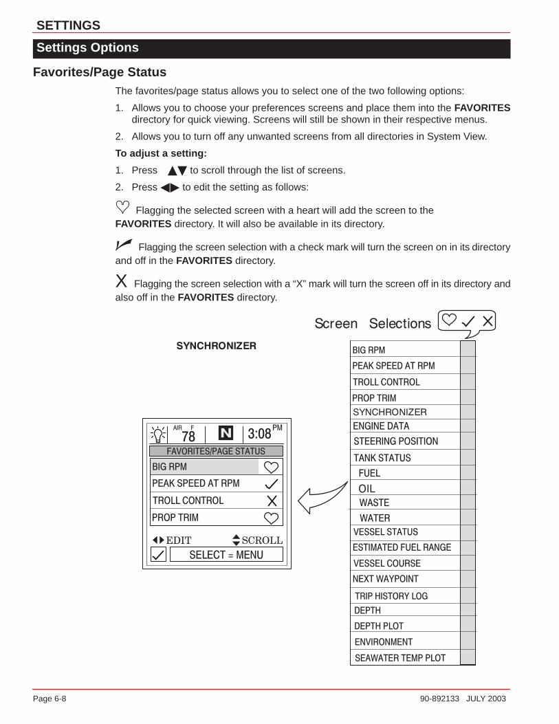
Favorites/Page StatusThe favorites/page status allows you to select one of the two following options:
1. Allows you to choose your preferences screens and place them into the FAVORITESdirectory for quick viewing. Screens will still be shown in their respective menus.
2. Allows you to turn off any unwanted screens from all directories in System View.
To adjust a setting:
1. Press �� to scroll through the list of screens.
2. Press �� to edit the setting as follows:
� Flagging the selected screen with a heart will add the screen to the FAVORITES directory. It will also be available in its directory.
� Flagging the screen selection with a check mark will turn the screen on in its directoryand off in the FAVORITES directory.
X Flagging the screen selection with a “X” mark will turn the screen off in its directory andalso off in the FAVORITES directory.

7
SYSTEM
90-892133 JULY 2003 Page 7-1
SYSTEMSection 7
Table of Contents
System Information 7-2. . . . . . . . . . . . . . . . . . . . . . . . . . . . . . . . . . . . . . . . . . . . . . . . . . . . . . . . . Entering the System Directory 7-2. . . . . . . . . . . . . . . . . . . . . . . . . . . . . . . . . . . . . . . . . . . . . . . System Directory 7-2. . . . . . . . . . . . . . . . . . . . . . . . . . . . . . . . . . . . . . . . . . . . . . . . . . . . . . . . . . . System Calibration 7-3. . . . . . . . . . . . . . . . . . . . . . . . . . . . . . . . . . . . . . . . . . . . . . . . . . . . . . . . .
Tank Configuration 7-4. . . . . . . . . . . . . . . . . . . . . . . . . . . . . . . . . . . . . . . . . . . . . . . . . . . . . . . Trim Calibration 7-6. . . . . . . . . . . . . . . . . . . . . . . . . . . . . . . . . . . . . . . . . . . . . . . . . . . . . . . . . Factory Defaults 7-7. . . . . . . . . . . . . . . . . . . . . . . . . . . . . . . . . . . . . . . . . . . . . . . . . . . . . . . . . User Keyless Code 7-8. . . . . . . . . . . . . . . . . . . . . . . . . . . . . . . . . . . . . . . . . . . . . . . . . . . . . .
Maintenance Log 7-10. . . . . . . . . . . . . . . . . . . . . . . . . . . . . . . . . . . . . . . . . . . . . . . . . . . . . . . . . . Recording Run Time 7-10. . . . . . . . . . . . . . . . . . . . . . . . . . . . . . . . . . . . . . . . . . . . . . . . . . . .
Active Alarms 7-11. . . . . . . . . . . . . . . . . . . . . . . . . . . . . . . . . . . . . . . . . . . . . . . . . . . . . . . . . . . . . Active Alarms 7-11. . . . . . . . . . . . . . . . . . . . . . . . . . . . . . . . . . . . . . . . . . . . . . . . . . . . . . . . . .
Alarm History 7-15. . . . . . . . . . . . . . . . . . . . . . . . . . . . . . . . . . . . . . . . . . . . . . . . . . . . . . . . . . . . . Alarm History 7-15. . . . . . . . . . . . . . . . . . . . . . . . . . . . . . . . . . . . . . . . . . . . . . . . . . . . . . . . . .

SYSTEM
Page 7-2 90-892133 JULY 2003
System Information
This Section will give a complete description of the screen settings in the SYSTEM directoryof the System View.
Some of the system functions are:
• Maintenance log
• Active alarms
• Alarm history
• System calibration
Entering the System Directory
To access the SYSTEM directory, use the trackpad to highlight the SYSTEM directory fromthe menu choice. Press SELECT to accept and to open the directory.
System Directory
System Directory Screen
SYSTEM
90-892133 JULY 2003 Page 7-3
System Calibration
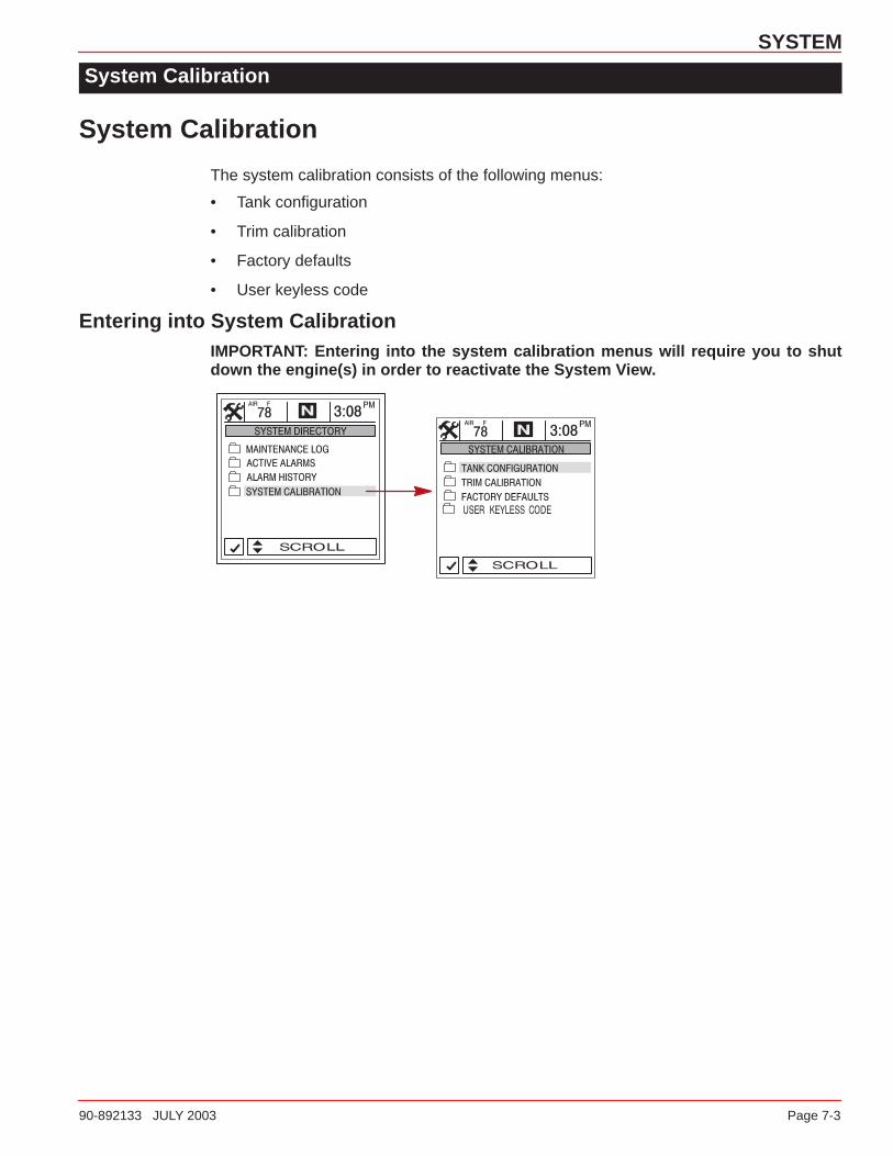
System Calibration
The system calibration consists of the following menus:
• Tank configuration
• Trim calibration
• Factory defaults
• User keyless code
Entering into System CalibrationIMPORTANT: Entering into the system calibration menus will require you to shutdown the engine(s) in order to reactivate the System View.

SYSTEM
Page 7-4 90-892133 JULY 2003
System Calibration
Tank ConfigurationNOTE: System View allows you to choose the name of the tanks you want to appear on thescreen. You can choose two tanks per engine.
1. Choose the names of the tank(s), that you would like to appear on screen. highlight thetank you would like to change. Press �� to display the list of names of available tanktypes. Select a name. Press SELECT to continue.
2. Enter the capacity of the tanks. Select the tank and press �� to enter the tank capacity.Press SELECT to continue.
TANK CONFIGURATION
1
2

SYSTEM
90-892133 JULY 2003 Page 7-5
System Calibration
Tank Configuration (Continued)NOTE: The fuel tank will have to be calibrated in order for System View to display fuel range.
3. There are two methods for calibrating fuel tank level:
a. Method 1 – Select DEFAULT – The System View will automatically supply an esti-mated range value based on default sensor values. This mode does not factor inirregular tank shapes. Press SELECT to save.
b. Method 2 – Select ADD FUEL – This method requires adding fuel at certain calibra-tion points. System View will display an estimated range value that factors in the tankshape.
NOTE: You will have to start with an empty fuel tank and manually fill the tank to the valuesgiven per instruction.
4. If using Method 2 , add fuel as shown in illustration below.
Method 1Method 2
3
4
SYSTEM
Page 7-6 90-892133 JULY 2003
System Calibration
Trim Calibration
CALIBRATING THE TRIM SENSOR
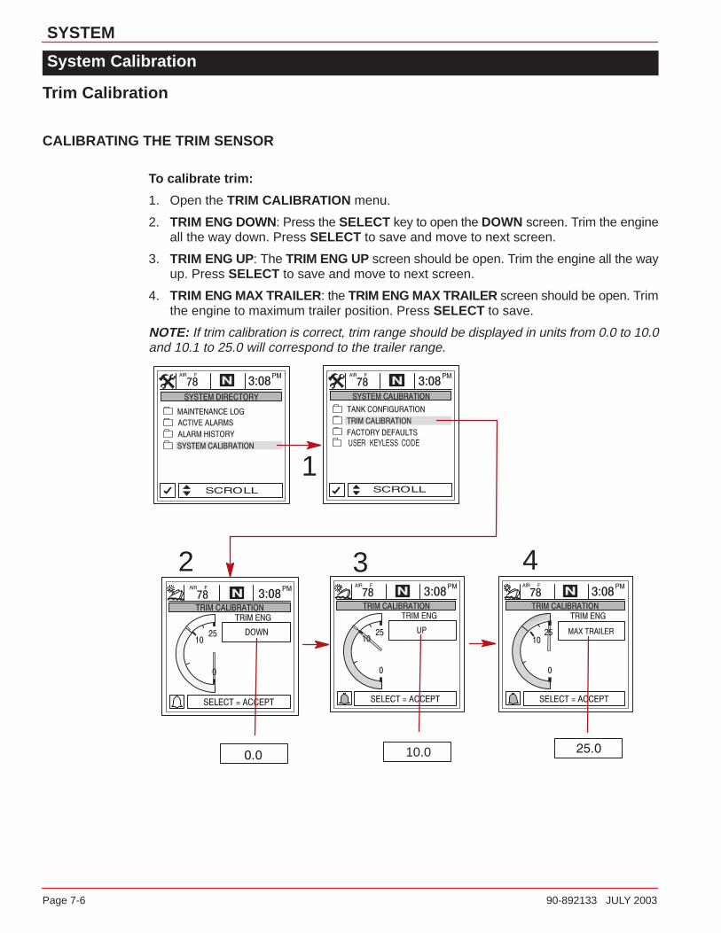
To calibrate trim:
1. Open the TRIM CALIBRATION menu.
2. TRIM ENG DOWN: Press the SELECT key to open the DOWN screen. Trim the engineall the way down. Press SELECT to save and move to next screen.
3. TRIM ENG UP: The TRIM ENG UP screen should be open. Trim the engine all the wayup. Press SELECT to save and move to next screen.
4. TRIM ENG MAX TRAILER : the TRIM ENG MAX TRAILER screen should be open. Trimthe engine to maximum trailer position. Press SELECT to save.
NOTE: If trim calibration is correct, trim range should be displayed in units from 0.0 to 10.0and 10.1 to 25.0 will correspond to the trailer range.
1
2 3
10.0
4

SYSTEM
90-892133 JULY 2003 Page 7-7
System Calibration
Factory Defaults
RESET SETTINGS DIRECTORY
Restores all settings back to System View’s original setup values.
To restore settings back to original setup values:
1. Open FACTORY DEFAULTS menu.
2. Press �� to highlight RESET SETTINGS DIRECTORY selection.
3. Select YES to reset or NO if you want to cancel.
RESET SENSOR DETECTION
At first power up, the System View will automatically detect all the sensors connected to it.If you would like the System View to re-start this sensor detection process over again, usethe following procedure.
To reset sensor detection:
4. Open FACTORY DEFAULTS menu.
5. Press �� to highlight RESET SENSOR DETECTION selection.
6. Select YES to reset or NO if you want to cancel.
1-4
2
5
3
6
SYSTEM
Page 7-8 90-892133 JULY 2003
System Calibration
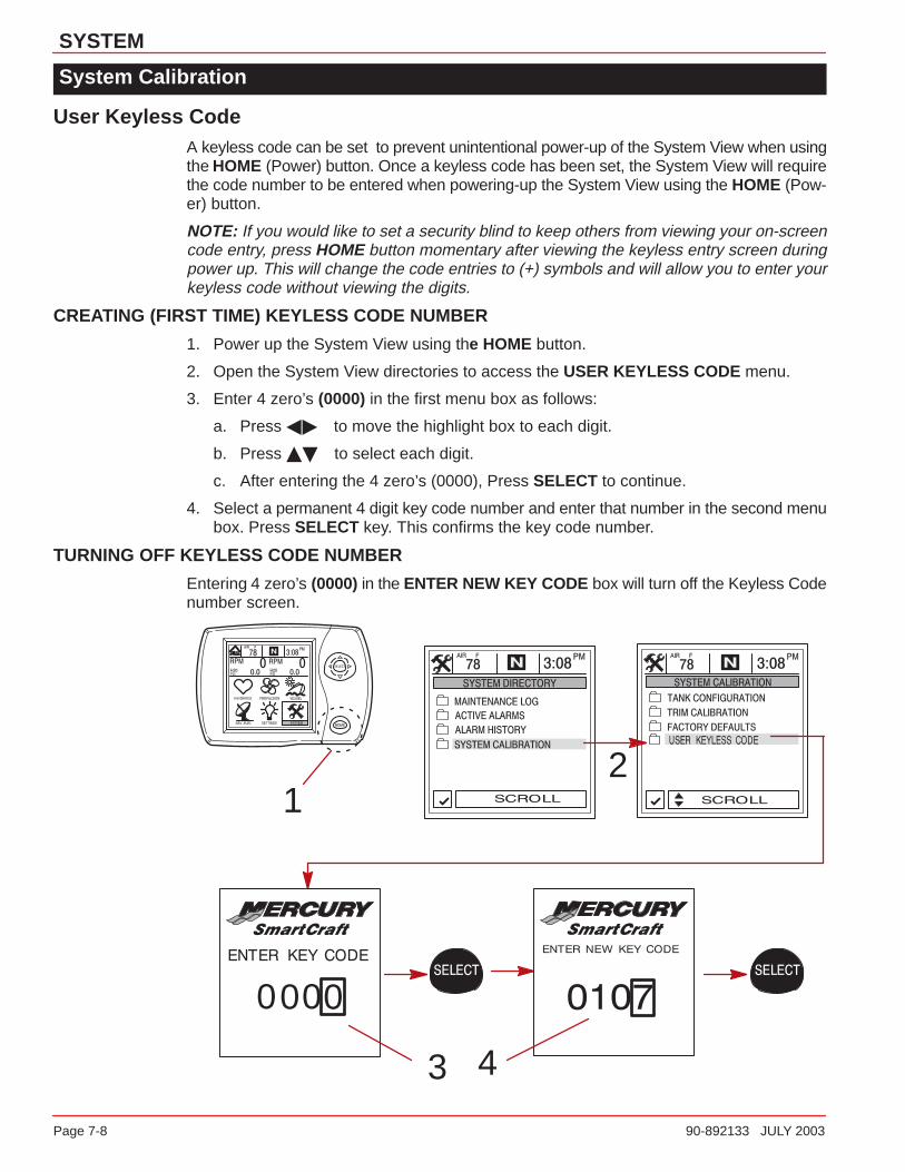
User Keyless CodeA keyless code can be set to prevent unintentional power-up of the System View when usingthe HOME (Power) button. Once a keyless code has been set, the System View will requirethe code number to be entered when powering-up the System View using the HOME (Pow-er) button.
NOTE: If you would like to set a security blind to keep others from viewing your on-screencode entry, press HOME button momentary after viewing the keyless entry screen duringpower up. This will change the code entries to (+) symbols and will allow you to enter yourkeyless code without viewing the digits.
CREATING (FIRST TIME) KEYLESS CODE NUMBER
1. Power up the System View using the HOME button.
2. Open the System View directories to access the USER KEYLESS CODE menu.
3. Enter 4 zero’s (0000) in the first menu box as follows:
a. Press �� to move the highlight box to each digit.
b. Press �� to select each digit.
c. After entering the 4 zero’s (0000), Press SELECT to continue.
4. Select a permanent 4 digit key code number and enter that number in the second menubox. Press SELECT key. This confirms the key code number.
TURNING OFF KEYLESS CODE NUMBER
Entering 4 zero’s (0000) in the ENTER NEW KEY CODE box will turn off the Keyless Codenumber screen.
1
0000
3
2
4

SYSTEM
90-892133 JULY 2003 Page 7-9
System Calibration
User Keyless CodeCHANGING YOUR KEYLESS CODE NUMBER
1. Power up the System View using the HOME button.
2. Open the System View directories to access the USER KEYLESS CODE menu.
3. Enter your existing 4 digit key code number in the first menu box as follows:
a. Press �� to move the highlight box to each digit.
b. Press �� to select each digit.
c. After entering the 4 digit number, press SELECT to continue.
4. Select a new 4 digit key code number and enter that number in the second menu box.Press SELECT key. This confirms the new key code number.
1
3
2
4
SYSTEM
Page 7-10 90-892133 JULY 2003
Maintenance Log
Maintenance Log
RECORDING RUN TIME
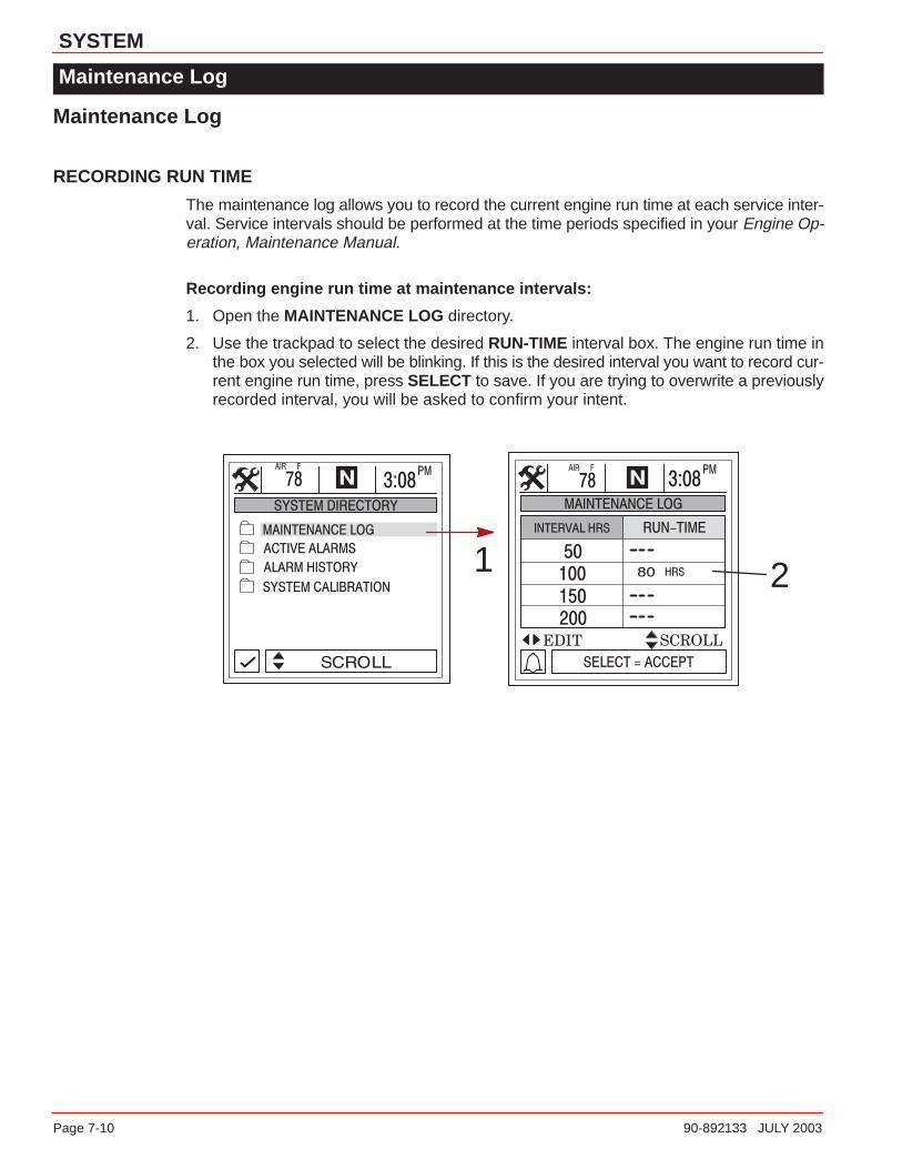
The maintenance log allows you to record the current engine run time at each service inter-val. Service intervals should be performed at the time periods specified in your Engine Op-eration, Maintenance Manual.
Recording engine run time at maintenance intervals:
1. Open the MAINTENANCE LOG directory.
2. Use the trackpad to select the desired RUN-TIME interval box. The engine run time inthe box you selected will be blinking. If this is the desired interval you want to record cur-rent engine run time, press SELECT to save. If you are trying to overwrite a previouslyrecorded interval, you will be asked to confirm your intent.
1 2
SYSTEM
90-892133 JULY 2003 Page 7-11
Active Alarms
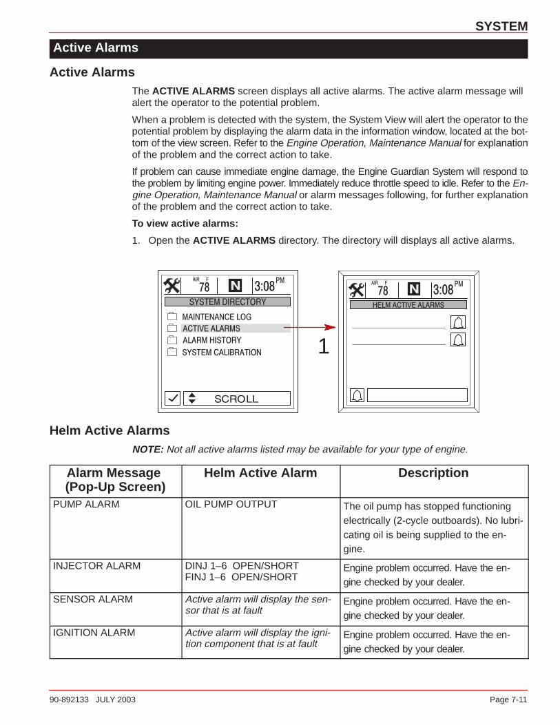
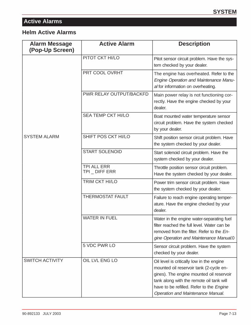
Active AlarmsThe ACTIVE ALARMS screen displays all active alarms. The active alarm message will alert the operator to the potential problem.
When a problem is detected with the system, the System View will alert the operator to thepotential problem by displaying the alarm data in the information window, located at the bot-tom of the view screen. Refer to the Engine Operation, Maintenance Manual for explanationof the problem and the correct action to take.
If problem can cause immediate engine damage, the Engine Guardian System will respond tothe problem by limiting engine power. Immediately reduce throttle speed to idle. Refer to the En-gine Operation, Maintenance Manual or alarm messages following, for further explanationof the problem and the correct action to take.
To view active alarms:
1. Open the ACTIVE ALARMS directory. The directory will displays all active alarms.
1
Helm Active AlarmsNOTE: Not all active alarms listed may be available for your type of engine.
Alarm Message (Pop-Up Screen)
Helm Active Alarm Description
PUMP ALARM OIL PUMP OUTPUT The oil pump has stopped functioningelectrically (2-cycle outboards). No lubri-cating oil is being supplied to the en-gine.
INJECTOR ALARM DINJ 1–6 OPEN/SHORTFINJ 1–6 OPEN/SHORT
Engine problem occurred. Have the en-gine checked by your dealer.
SENSOR ALARM Active alarm will display the sen-sor that is at fault
Engine problem occurred. Have the en-gine checked by your dealer.
IGNITION ALARM Active alarm will display the igni-tion component that is at fault
Engine problem occurred. Have the en-gine checked by your dealer.

SYSTEM
Page 7-12 90-892133 JULY 2003
Active Alarms
Helm Active Alarms
Alarm Message (Pop-Up Screen)
Active Alarm Description
PORT HEAD OVRHTSTBD HEAD OVRHTCOMPRESS OVRHT
The engine has overheated. Refer to theEngine Operation and Maintenance Manu-al for information on overheating.
BATTERY VOLT HI Battery voltage is above the allowable lim-it. Have the electrical system checked byyour dealer.
BATTERY VOLT LO Battery voltage is below the allowable limit.Have the electrical system checked byyour dealer.
BLOCk PRESSURE IS LOW The water pressure in the engine is low.Failed water pump. Check for blockage atthe water intake holes in the gear case.Have the engine checked by your dealer.
ESC-NS POS DIFFESC-ERC POS DIFFESC TIMEOUT
Electronic remote control circuit problem.Have the system checked by your dealer.
SYSTEM ALARMESC CONTROL LOST Electronic remote control problem oc-
curred. Have the system checked by yourdealer.
ETC CONTROLETC STICKING
Engine problem occurred. Have the en-gine checked by your dealer.
FUEL LVL CKT HI/LO Fuel level circuit problem. Have the sys-tem checked by your dealer.
FUEL PUMP RLY CKT Fuel pump problem. Have the systemchecked by your dealer.
HORN OUTPUT Warning horn is not functioning correctly.Have the system checked by your dealer.
IAC OUTPUT Idle air control is not functioning correctly.Have the system checked by your dealer.
LOW DRIVE LUBE Drive lube low or faultly low lube switch.
MAP IDLE ERR MAP sensor is not functioning correctly.Have the engine checked by your dealer.
OIL LVL CKT HI/LO Oil level circuit problem. Have the systemchecked by your dealer.
SYSTEM
90-892133 JULY 2003 Page 7-13
Active Alarms
Helm Active Alarms
Alarm Message (Pop-Up Screen)
Active Alarm Description
PITOT CKT HI/LO Pitot sensor circuit problem. Have the sys-tem checked by your dealer.
PRT COOL OVRHT The engine has overheated. Refer to theEngine Operation and Maintenance Manu-al for information on overheating.
PWR RELAY OUTPUT/BACKFD Main power relay is not functioning cor-rectly. Have the engine checked by yourdealer.
SEA TEMP CKT HI/LO Boat mounted water temperature sensorcircuit problem. Have the system checkedby your dealer.
SYSTEM ALARM SHIFT POS CKT HI/LO Shift position sensor circuit problem. Havethe system checked by your dealer.
START SOLENOID Start solenoid circuit problem. Have thesystem checked by your dealer.
TPI ALL ERRTPI _ DIFF ERR
Throttle position sensor circuit problem.Have the system checked by your dealer.
TRIM CKT HI/LO Power trim sensor circuit problem. Havethe system checked by your dealer.
THERMOSTAT FAULT Failure to reach engine operating temper-ature. Have the engine checked by yourdealer.
WATER IN FUEL Water in the engine water-separating fuelfilter reached the full level. Water can beremoved from the filter. Refer to the En-gine Operation and Maintenance Manual.0
5 VDC PWR LO Sensor circuit problem. Have the systemchecked by your dealer.
SWITCH ACTIVITY OIL LVL ENG LO Oil level is critically low in the enginemounted oil reservoir tank (2-cycle en-gines). The engine mounted oil reservoirtank along with the remote oil tank willhave to be refilled. Refer to the EngineOperation and Maintenance Manual.

SYSTEM
Page 7-14 90-892133 JULY 2003
Active Alarms
Helm Active Alarms
Alarm Message (Pop-Up Screen)
Active Alarm Description
ECT OVRHT Water temperature in engine is too hot.Cooling problem. Have the enginechecked by your dealer.
GUARDIAN Guardian is trying to protect the engine byreducing engine speed.
MAP DIFF ERR MAP INPUT HI/LO
MAP sensor is not functioning correctly.Have the engine checked by your dealer.
ENGINE POWER LIMITEDNEUTRAL OVERSPEED Recommended engine overspeed in neu-
tral has been exceeded.
OVERSPEED Recommended engine RPM range hasbeen exceeded.
PORT EMCT OVRHT Port exhaust manifold is overheating.Cooling problem. Have the enginechecked by your dealer.
REVERSE OVERSPEED Recommended engine overspeed in re-verse has been exceeded.
STB EMCT OVRHT Starboard exhaust manifold is overheat-ing. Cooling problem. Have the enginechecked by your dealer.
LOST COMMUNICATIONTO THE ENGINE
STBD MED SPD DATA LOST
STBD BACKUP ETCESC DATA
STSD ETCESC DATA LOST
STBD LOW SPD DATA LOSTDUAL CAN ERR
System View does not see the enginecomputer. Usually indicates that no data isbeing transferred from the engine’s com-puter to System View. Check wiring, alsomake sure both terminator resistors areinstalled in the bus.
DTS MODULE ALARM &SYSTEM ALARM
PRIMARY CTRL SOHCROSSCHECK SOH
Problem in the SmartCraft wiring system
COMMUNICATION LOSTTO ENGINE & DTS MOD-ULE ALARM
STBD MED SPD DATA LOSTSTBD LOW SPD DATA LOST
Problem in the SmartCraft wiring system
SYSTEM
90-892133 JULY 2003 Page 7-15
Alarm History
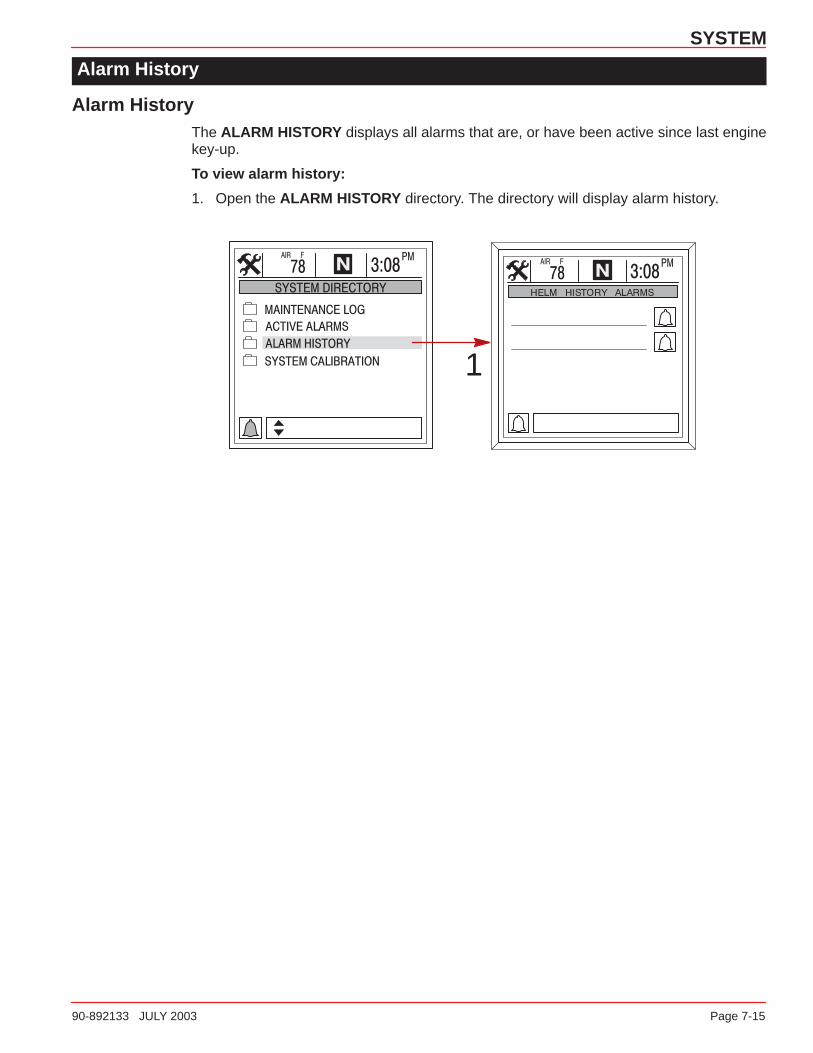
Alarm HistoryThe ALARM HISTORY displays all alarms that are, or have been active since last enginekey-up.
To view alarm history:
1. Open the ALARM HISTORY directory. The directory will display alarm history.
1
8
INSTALLATION
90-892133 JULY 2003 Page 8-1
INSTALLATIONSection 8
Table of Contents
Components 8-2. . . . . . . . . . . . . . . . . . . . . . . . . . . . . . . . . . . . . . . . . . . . . . . . . . . . . . . . . . . . . . . Special Information 8-2. . . . . . . . . . . . . . . . . . . . . . . . . . . . . . . . . . . . . . . . . . . . . . . . . . . . . . . . . Installation Information 8-2. . . . . . . . . . . . . . . . . . . . . . . . . . . . . . . . . . . . . . . . . . . . . . . . . . . . . . System View Installation 8-3. . . . . . . . . . . . . . . . . . . . . . . . . . . . . . . . . . . . . . . . . . . . . . . . . . . . Wiring 8-4. . . . . . . . . . . . . . . . . . . . . . . . . . . . . . . . . . . . . . . . . . . . . . . . . . . . . . . . . . . . . . . . . . . . Connecting Optional GPS Unit to the System View 8-7. . . . . . . . . . . . . . . . . . . . . . . . . . . . . Setup for Multi Engine Location 8-7. . . . . . . . . . . . . . . . . . . . . . . . . . . . . . . . . . . . . . . . . . . . . .
INSTALLATION
Page 8-2 90-892133 JULY 2003
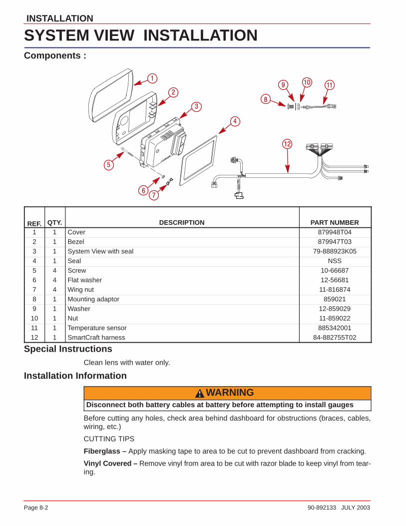
SYSTEM VIEW INSTALLATIONComponents :
�
�
�
�
�
�
�
����
��
REF. QTY. DESCRIPTION PART NUMBER1 1 Cover 879948T042 1 Bezel 879947T033 1 System View with seal 79-888923K05
4 1 Seal NSS5 4 Screw 10-666876 4 Flat washer 12-566817 4 Wing nut 11-8168748 1 Mounting adaptor 8590219 1 Washer 12-85902910 1 Nut 11-859022
11 1 Temperature sensor 88534200112 1 SmartCraft harness 84-882755T02
Special InstructionsClean lens with water only.
Installation Information
WARNINGDisconnect both battery cables at battery before attempting to install gauges
Before cutting any holes, check area behind dashboard for obstructions (braces, cables,wiring, etc.)
CUTTING TIPS
Fiberglass – Apply masking tape to area to be cut to prevent dashboard from cracking.
Vinyl Covered – Remove vinyl from area to be cut with razor blade to keep vinyl from tear-ing.
INSTALLATION
90-892133 JULY 2003 Page 8-3
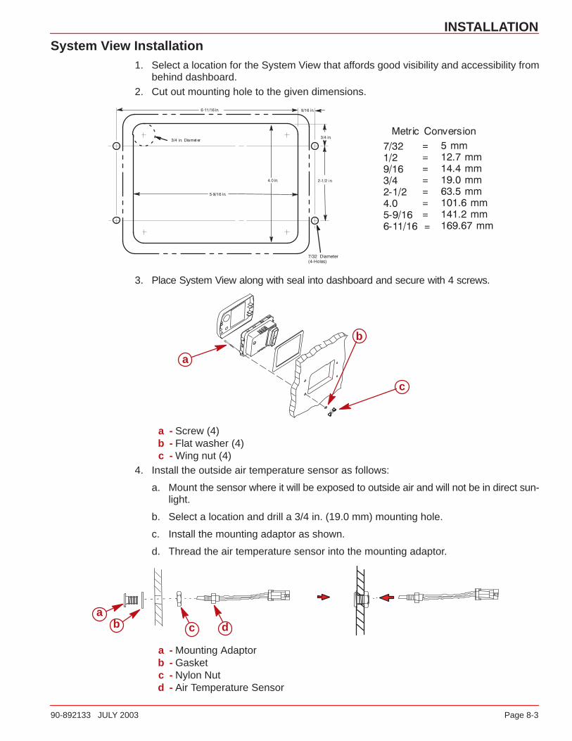
System View Installation1. Select a location for the System View that affords good visibility and accessibility from
behind dashboard.2. Cut out mounting hole to the given dimensions.
3. Place System View along with seal into dashboard and secure with 4 screws.
a
b
c
a - Screw (4)b - Flat washer (4)c - Wing nut (4)
4. Install the outside air temperature sensor as follows:
a. Mount the sensor where it will be exposed to outside air and will not be in direct sun-light.
b. Select a location and drill a 3/4 in. (19.0 mm) mounting hole.
c. Install the mounting adaptor as shown.
d. Thread the air temperature sensor into the mounting adaptor.
ab c d
a - Mounting Adaptorb - Gasketc - Nylon Nutd - Air Temperature Sensor

INSTALLATION
Page 8-4 90-892133 JULY 2003
Wiring
MODELS WITHOUT ELECTRONIC THROTTLE/SHIFTNOTE: Extension Wiring Harnesses for the System Link gauges are available in 3 ft, 10 ftand 30 ft lengths. (84-880756b-3,10,30)
a
b
c
d
g
e
f
h
ij
k
–+
l
a - System viewb - Display harnessc - System link gauge connection – (starboard)d - System link gauge connection – (port)e - GPS (Optional) connectionf - Horn – (provided with display harness)g - Terminatorh - Weather coveri - Junction boxj - SC data cable – (from engine)k - Air temperature sensor – (provided with display harness)l - Not used (seal connection with weather cap)
INSTALLATION
90-892133 JULY 2003 Page 8-5
Wiring
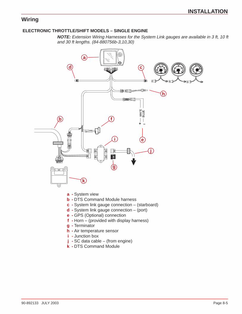
ELECTRONIC THROTTLE/SHIFT MODELS – SINGLE ENGINENOTE: Extension Wiring Harnesses for the System Link gauges are available in 3 ft, 10 ftand 30 ft lengths. (84-880756b-3,10,30)
–+b
cd
f
g
h
i
j
e
a
k
a - System viewb - DTS Command Module harnessc - System link gauge connection – (starboard)d - System link gauge connection – (port)e - GPS (Optional) connectionf - Horn – (provided with display harness)g - Terminatorh - Air temperature sensori - Junction boxj - SC data cable – (from engine)k - DTS Command Module
INSTALLATION
Page 8-6 90-892133 JULY 2003
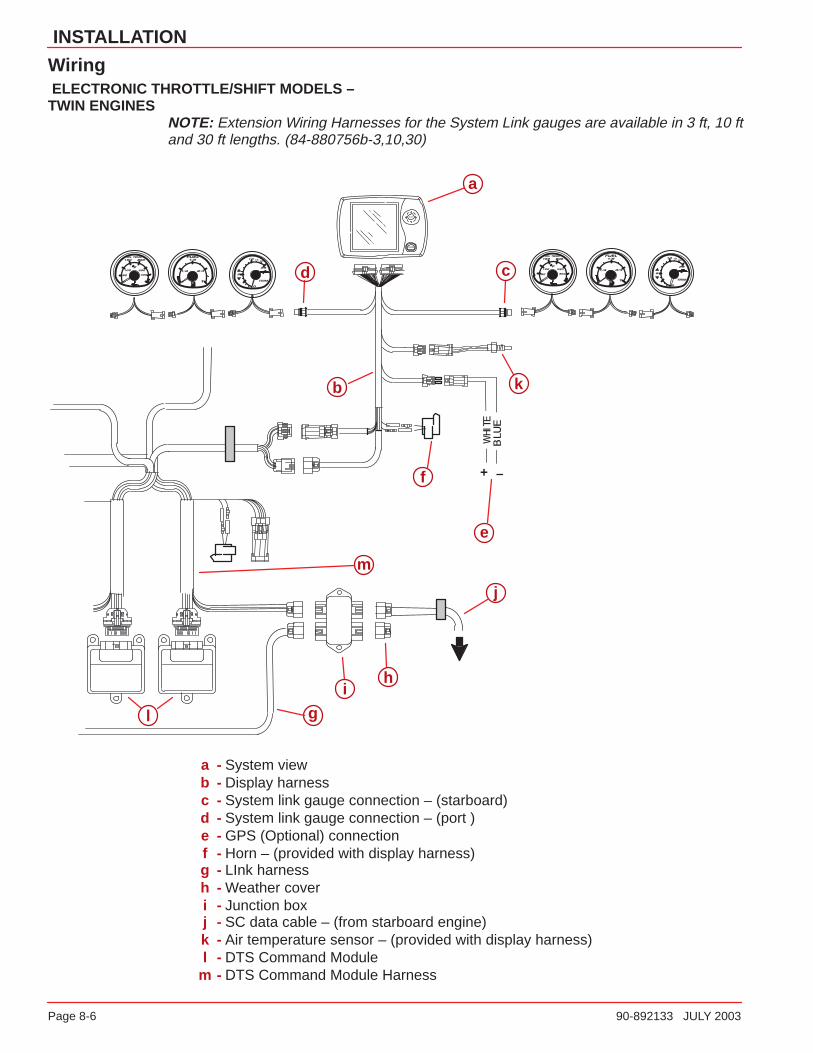
Wiring ELECTRONIC THROTTLE/SHIFT MODELS –TWIN ENGINES
NOTE: Extension Wiring Harnesses for the System Link gauges are available in 3 ft, 10 ftand 30 ft lengths. (84-880756b-3,10,30)
–+
e
a
b
cd
f
g
hi
j
k
l
m
a - System viewb - Display harnessc - System link gauge connection – (starboard)d - System link gauge connection – (port )e - GPS (Optional) connectionf - Horn – (provided with display harness)g - LInk harnessh - Weather coveri - Junction boxj - SC data cable – (from starboard engine)k - Air temperature sensor – (provided with display harness)l - DTS Command Module
m - DTS Command Module Harness

INSTALLATION
90-892133 JULY 2003 Page 8-7
Connecting Optional GPS Unit to the System ViewNOTE: The GPS unit must comply to the National Marine Electronic Association NMEA0183 Interface Standard v1.5, v2.0 or later compatible version.
First, look at the GPS wiring diagram and determine what two leads are the GPS outputleads. Locate the White and Blue wires coming from the System View wiring harness (seeWiring). Connect the GPS output leads to the white and blue wires. If no data is received,switch the wire connections around. If no data is still received, refer the GPS owner’s manualand see if the GPS has to be calibrated to turn on the output signal or needs to be groundeddifferently.
Setup for Multi Engine LocationIn multiple engine applications, each engine must be assigned a location. For example, star-board and port. This is required for the correct engine data to be transmitted to the SystemView.If the System View should ever detect an incorrect engine location, it will alert you bydisplaying a multi engine fault message. If this should happen, reset the engine locationsusing the Quicksilver Digital Diagnostic Terminal (DDT) along with SmartCraft Engine Diag-nostic Cartridge Version 1.0 or newer.

9
INDEX
90-892133 JULY 2003 Page 9-1
INDEXSection 9
AAlarms– Active 7-11. . . . . . . . . . . . . . . . . .
Air Temperature 5-6. . . . . . . . . . . . . . . .
Alarm History 7-15. . . . . . . . . . . . . . . . . .
Alarm Message Screens 2-9. . . . . . . . .
BBoat Speed 5-6. . . . . . . . . . . . . . . . . . . .
Brightness 6-3. . . . . . . . . . . . . . . . . . . . .
CClock Settings 6-3. . . . . . . . . . . . . . . . . .
Connecting GPS Unit to the System View 8-7. . . . . . . . . . . . . . . .
Contrast 6-3. . . . . . . . . . . . . . . . . . . . . . .
DData Display Screen 2-5. . . . . . . . . . . .
Depth 5-5. . . . . . . . . . . . . . . . . . . . . . . . .
Depth Alarm 6-6. . . . . . . . . . . . . . . . . . .
Depth Offset 6-4. . . . . . . . . . . . . . . . . . .
Depth Plot LIne 5-5. . . . . . . . . . . . . . . . .
Display Screens 2-2. . . . . . . . . . . . . . . .
EEngine Data Screens 3-4. . . . . . . . . . . .
Engine RPM Synchronizer 3-4. . . . . . .
Engine RPM/Speed 3-3. . . . . . . . . . . . .
Environment 5-6. . . . . . . . . . . . . . . . . . .
FFavorite Page Screen Selection 6-8. .
Favorite Page Status 6-8. . . . . . . . . . . .
Favorite Slide Pause Setting 6-7. . . . .
Favorite Slide Show Option 6-7. . . . . .
Fuel Flow 5-7. . . . . . . . . . . . . . . . . . . . . .
Fuel Range 5-7. . . . . . . . . . . . . . . . . . . .
Fuel Remaining 5-7. . . . . . . . . . . . . . . .
Fuel Tanks 4-4. . . . . . . . . . . . . . . . . . . . .
GGPS Heading Selection 6-7. . . . . . . . .
HHome Page Data 6-5. . . . . . . . . . . . . . .
Home Page Screens 2-3. . . . . . . . . . . .
IInstallation 8-3. . . . . . . . . . . . . . . . . . . . .
Invert Steering 6-6. . . . . . . . . . . . . . . . .
KKeyless Code 7-8. . . . . . . . . . . . . . . . . . .
Keypad Usage 1-2. . . . . . . . . . . . . . . . .
LLanguage 6-4. . . . . . . . . . . . . . . . . . . . . .
MMaintenance Log 7-10. . . . . . . . . . . . . . .
NNavigation Screens 5-3. . . . . . . . . . . . .
Navigation/Fuel Directory 5-2. . . . . . . .
Next Waypoint Data 5-4. . . . . . . . . . . . .
PPaddle Frequency 6-6. . . . . . . . . . . . . .
Peak Speed at RPM 3-3. . . . . . . . . . . .
Pilot Multiplier 6-6. . . . . . . . . . . . . . . . . .
Pilot Sensor 6-6. . . . . . . . . . . . . . . . . . . .
Preference Settings 6-7. . . . . . . . . . . . .
Propulsion Directory 3-2. . . . . . . . . . . .
RResetting Sensor Detection 7-7. . . . . . .
Restoring Factory Settings 7-7. . . . . . .
SSeawater Temperature Offset 6-4. . . .
Seawater Temperature Plot 5-6. . . . . .
Sensors 6-6. . . . . . . . . . . . . . . . . . . . . . .
Setting Directory 6-2. . . . . . . . . . . . . . . .
Settings Information 6-2. . . . . . . . . . . . .
Setup for Engine Location 8-7. . . . . . .
Shallow Alarm 6-6. . . . . . . . . . . . . . . . . .

INDEX
Page 9-2 90-892133 JULY 2003
Start–up Page Preference 6-7. . . . . . .
Start–up Screens 2-2. . . . . . . . . . . . . . .
Starting Up the System View 2-2. . . . . .
Steering Offset 6-4. . . . . . . . . . . . . . . . .
Steering Position 4-3. . . . . . . . . . . . . . .
System Calibration 7-3. . . . . . . . . . . . . .
System Directory 7-2. . . . . . . . . . . . . . .
System Information 7-2. . . . . . . . . . . . . .
TTank Configuration 7-4. . . . . . . . . . . . . .
Tank Status 4-3. . . . . . . . . . . . . . . . . . . .
Time Settings 6-3. . . . . . . . . . . . . . . . . .
Transition Speed 6-6. . . . . . . . . . . . . . .
Trim Calibration 7-6. . . . . . . . . . . . . . . . .
Trim Position 3-5. . . . . . . . . . . . . . . . . . .
Trip History Log 5-4. . . . . . . . . . . . . . . .
Troll Control 3-6. . . . . . . . . . . . . . . . . . . .
Turning Off Troll Control 3-6. . . . . . . . .
Troll Control Setting 3-6. . . . . . . . . . . . .
UUnits (English or Metric) 6-4. . . . . . . . .
VVessel Course 5-3. . . . . . . . . . . . . . . . . .
Vessel Directory, 4-2. . . . . . . . . . . . . . . .
Vessel Status 4-5. . . . . . . . . . . . . . . . . .
WWarning Horn 6-7. . . . . . . . . . . . . . . . . .
Water and Waste Tanks 4-4. . . . . . . . .
Water Temperature 5-6. . . . . . . . . . . . .
Wiring 8-4. . . . . . . . . . . . . . . . . . . . . . . . .


