Instruction Manual Read and Understand Instructions prior to use For use in areas known to be free of combustible gas hazards For use in areas that are clean and dry SCAL-400 CALIBRATION AND CHARGING STATION FOR USE WITH SENSIT® P400 GAS MONITORS 851 Transport Drive Valparaiso, IN 46383-8432 MADE IN USA SENSIT Technologies is in compliance with ISO 9001:2008 Phone: 888 4SENSIT 888 473 6748 219 465 2700 Fax: 219 465 2701 www.gasleaksensors.com
Transcript
Instruction ManualRead and Understand Instructions prior to use
For use in areas known to be free of combustible gas hazardsFor use in areas that are clean and dry
SCAL-400CALIBRATION AND CHARGING STATION
FOR USE WITH SENSIT® P400 GAS MONITORS
851 Transport DriveValparaiso, IN 46383-8432
MADE IN USA
SENSIT Technologies is in compliance with ISO 9001:2008
Warranty .................................................... Back Cover
SCAL-400CALIBRATION AND CHARGING STATION
FOR USE WITH SENSIT® P400 GAS MONITORS
Specifications
Power: 100 – 240 VAC input
Size: 24” X 7” X 3” (61cm X 17.8cm X 7.6cm)
Weight: 5.75 lbs. (2.6 kg)
Operational Temperature: 40 ‐ 122°F (5 ‐ 50°C)
Maximum inlet pressure: 20psi
Features
Touch screen display LED status indicators Charging pins Communication pin
Power connection RJ45 Serial
Connections
Cooling fan intake Gas inlets/connections
4
What’s Included:
SCAL-400
Power Cord (120 VAC)
Instruction Manual
SCAL-D Software
USB Cable
54 / 12
Description
The SCal‐400 is a multi‐unit charging and calibration station for Sensit P400 gas detection instruments. It can bump test and/or calibrate up to five P400 units consecutively while simultaneously recharging the battery packs. The SCal‐400 also detects if a P400 requires calibration or a bump test when connected and automatically performs the required test. During connection any manually performed calibration and bump tests in the instrument memory log will automatically transfer from P400 to SCal‐400. Data management for the SCal‐400 requires either SCal‐D or SCal‐N software packages. All SCal‐400 stations come standard with SCal‐D software for desktop application.
The location to place any instrument is referred to as a “slot”. For each slot there are charger and communication connections as well as LEDs to indicate the status. All testing functions require no user interaction.
The display is a touchscreen. Instrument and station information can be accessed by using your finger or the included stylus.
The SCal‐400 scans each slot, updates the LED status, and refreshes the display screen for each slot every three seconds. During communication, the SCal‐400 completes any log transfer before scanning another slot.
LED Status
Each slot has two LEDs indicating the status for the docked instrument. The following table describes the various LED states:
SCal‐400 Individual Slot LED Status: Green LED Red LED Description
1 OFF OFF Nothing on slot 2 ON OFF Ready (all test done, fully charged/alkaline OK) 3 OFF ON Fail calibration/bump test/alkaline low battery 4 BLINK ON/OFF/BLINK Charging 5 ON/BLINK BLINK Test in progress/pending
65 / 12
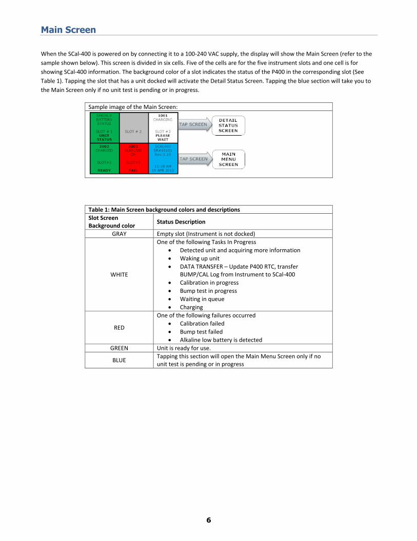
Main Screen
When the SCal‐400 is powered on by connecting it to a 100‐240 VAC supply, the display will show the Main Screen (refer to the sample shown below). This screen is divided in six cells. Five of the cells are for the five instrument slots and one cell is for showing SCal‐400 information. The background color of a slot indicates the status of the P400 in the corresponding slot (See Table 1). Tapping the slot that has a unit docked will activate the Detail Status Screen. Tapping the blue section will take you to the Main Screen only if no unit test is pending or in progress.
Sample image of the Main Screen:
Table 1: Main Screen background colors and descriptionsSlot Screen Background color Status Description
GRAY Empty slot (Instrument is not docked)
WHITE
One of the following Tasks In Progress Detected unit and acquiring more information Waking up unit DATA TRANSFER – Update P400 RTC, transfer
BUMP/CAL Log from Instrument to SCal‐400 Calibration in progress Bump test in progress Waiting in queue Charging
RED
One of the following failures occurred Calibration failed Bump test failed Alkaline low battery is detected
GREEN Unit is ready for use.
BLUE Tapping this section will open the Main Menu Screen only if no unit test is pending or in progress
76 / 12
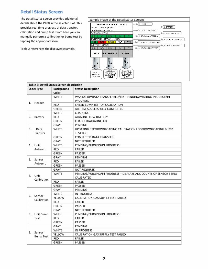
Detail Status Screen The Detail Status Screen provides additional details about the P400 in the selected slot. This provides real time progress of data transfer, calibration and bump test. From here you can manually perform a calibration or bump test by tapping the appropriate icon.
Table 2 references the displayed example.
Sample image of the Detail Status Screen:
Table 2: Detail Status Screen description Label Type Background
Color Status Description
1. Header
WHITE WAKING UP/DATA TRANSFERRED/TEST PENDING/WAITING IN QUEUE/IN PROGRESS
RED FAILED BUMP TEST OR CALIBRATIONGREEN ALL TEST SUCCESSFULLY COMPLETED
2. Battery WHITE CHARGINGRED ALKALINE: LOW BATTERYGREEN CHARGED/ALKALINE: OK
GRAY NOT REQUIREDWHITE PENDING/PURGING/IN PROGRESSRED FAILEDGREEN PASSED
5. Sensor Autozero
GRAY PENDINGRED FAILEDGREEN PASSED
6. Unit Calibration
GRAY NOT REQUIREDWHITE PENDING/PURGING/IN PROGRESS – DISPLAYS ADC COUNTS OF SENSOR BEING
CALIBRATED RED FAILEDGREEN PASSED
7. Sensor Calibration
GRAY PENDINGWHITE IN PROGRESSYELLOW CALIBRATION GAS SUPPLY TEST FAILEDRED FAILEDGREEN PASSED
8. Unit Bump Test
GRAY NOT REQUIREDWHITE PENDING/PURGING/IN PROGRESSRED FAILEDGREEN PASSED
9. Sensor Bump Test
GRAY PENDINGWHITE IN PROGRESSYELLOW CALIBRATION GAS SUPPLY TEST FAILEDRED FAILEDGREEN PASSED
87 / 12
Main Menu Screen
The Main Menu Screen provides an overview of the system (Serial #, Software Rev#, Date and Time, Valve Configuration). It also provides access to view calibration gas information, view logs, update settings through the Supervisor Menu, and a Test Menu.
The Valve Setup Overview provides information about which gas inlets (valves) are configured for each calibration gas. Each lure inlet on the manifold is color coded with label around it.
The Supervisor and Test Menu screens are password protected.
Calibration Gas Information Screen This screen is divided in eight cells. Each cell represents a single gas inlet (valve). The background colors and gas inlets are color coded and matched for easy identification. The colors on the manifold label correspond to the colors shown on this screen. It also provides the information about type of regulator required for the gas bottle and the expiration date of the calibration gas. A blank/empty cell indicates that particular gas inlet (valve) is not configured and will not be used. “N/A” in a cell indicates that the valve is not installed. Tapping on a configured cell (i.e. ‐ not blank/empty) will take you the password screen. Upon providing the correct password, the calibration gas information will be displayed.
Sample image of the Main Screen:
Sample image of the Calibration Gas Information Screen:
98 / 12
Log Review Screen This screen lets you review all the logs available in the SCal‐400s local database. It will display the most recent log first, but other logs can be viewed by using the “PREV” and “NEXT” buttons. NOTE: you cannot see logs from other stations or SCal‐N/D databases.
Table 3 references the displayed example.
Password Screen The Password Screen provides a supervisor level of protection to access the Supervisor and Test Menus and the menu to update the calibration gas information. The password is four numbers long. Tapping the “CLEAR” button will reset the boxes, allowing you to try again. After you enter four numbers, the password will automatically be checked. Upon providing the correct password, the next screen will be displayed. Entering an incorrect password will change the screen title to be displayed as “WRONG PASSWORD” in red. After three unsuccessful attempts, the password screen will close and you will return to the previous screen.
Sample image of the Log Review Screen:
Table 3: Log Review Screen background colors and descriptionsType Background
Color Description
Serial # NA Displays the serial number of the P400 unitType NA Displays the type of log: BUMP/CAL
Result Bar
Result bar is divided in 5 cells. Each cell represents sensor calibration/bump result.
RED FAILED: BUMP FAILEDCAL FAILED: CALIBRATION FAILED ZERO FAILED
YELLOW CAL GAS FAILED: Calibration gas supply check failedGRAY Sensor Test (calibration/bump) is skipped by userGREEN PASSED
Sample image of the Password Screen:
10
Supervisor Menu Screen: The settings of the SCal‐400 can be changed from within the Supervisor Menu. Please see Table 4 for a list of all the configurable items that can be modified. You can use the vertical scroll bar to view all available options. Scroll to and tap the button for the setting you would like to change. Another screen will appear that will allow you to view/adjust the current setting.
Table 4: Supervisor Menu Items
1 SET TIME ZONE
This allows you to set the time zone of the clock. Updating this setting will restart the SCal‐400 application. All available time zones will be listed. Select the appropriate time zone and click “UPDATE”. A message box will be displayed to indicate system will restart. Click “OK” to continue.
2 SET CLOCK
This allows you to change the date and time of the clock.
Select Value Screen: The header of this screen will display the name of the setting you are changing. “LL” and “UL” in the sample image will be replaced by the lower limit and upper limit numbers for the selected setting. Click the “ACCEPT” button to update the value.
Enable/Disable Screen: The header of this screen will display the name of the setting you are changing. This screen allows you to enable or disable the selected feature. Click the “ACCEPT” button to update the value.
1110 / 12
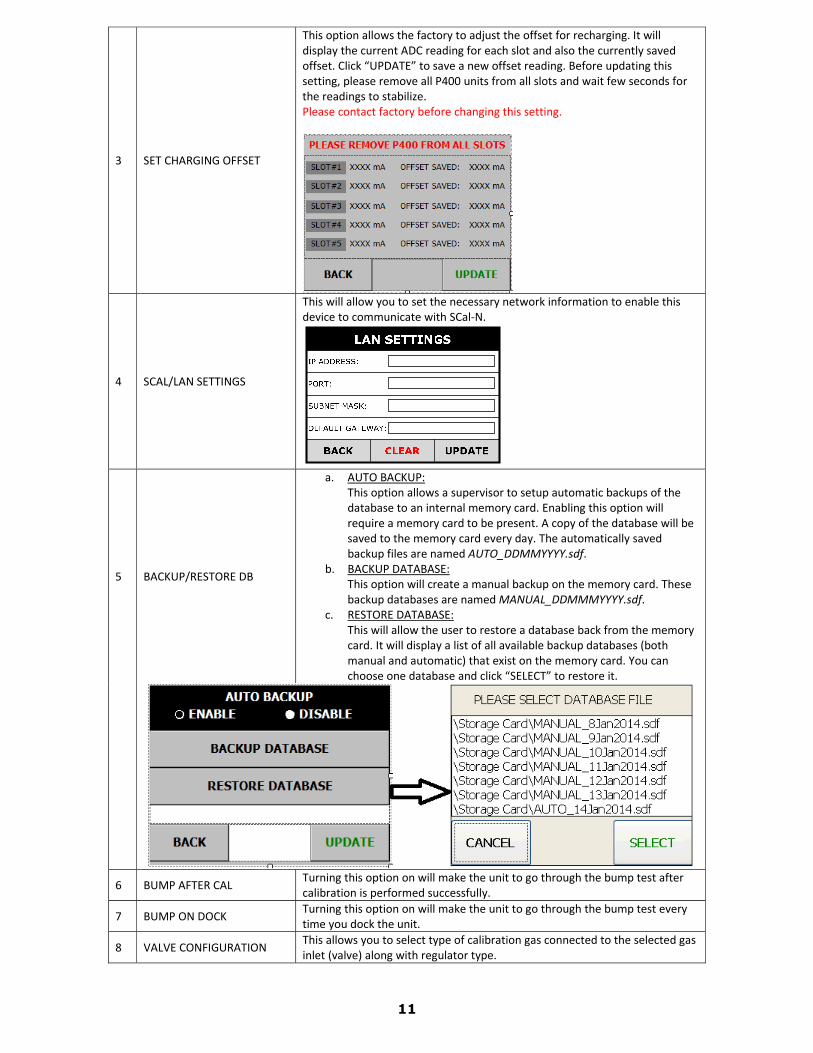
3 SET CHARGING OFFSET
This option allows the factory to adjust the offset for recharging. It will display the current ADC reading for each slot and also the currently saved offset. Click “UPDATE” to save a new offset reading. Before updating this setting, please remove all P400 units from all slots and wait few seconds for the readings to stabilize. Please contact factory before changing this setting.
4 SCAL/LAN SETTINGS
This will allow you to set the necessary network information to enable this device to communicate with SCal‐N.
5 BACKUP/RESTORE DB
a. AUTO BACKUP:This option allows a supervisor to setup automatic backups of the database to an internal memory card. Enabling this option will require a memory card to be present. A copy of the database will be saved to the memory card every day. The automatically saved backup files are named AUTO_DDMMYYYY.sdf.
b. BACKUP DATABASE: This option will create a manual backup on the memory card. These backup databases are named MANUAL_DDMMMYYYY.sdf.
c. RESTORE DATABASE: This will allow the user to restore a database back from the memory card. It will display a list of all available backup databases (both manual and automatic) that exist on the memory card. You can choose one database and click “SELECT” to restore it.
6 BUMP AFTER CAL Turning this option on will make the unit to go through the bump test after calibration is performed successfully.
7 BUMP ON DOCK Turning this option on will make the unit to go through the bump test every time you dock the unit.
8 VALVE CONFIGURATION This allows you to select type of calibration gas connected to the selected gas inlet (valve) along with regulator type.
1211 / 12
Valve configuration screen: The middle section of this screen is divided in eight cells. Each cell represents a single gas inlet (valve). The background colors and gas inlets are color coded and matched for easy identification. The colors on the manifold label correspond to the colors shown on this screen. It also provides the information about the type of regulator required for the gas bottle and the expiration date of the calibration gas. A blank/empty cell indicates that particular gas inlet is not configured and will not be used. “N/A” in a cell indicates that the valve is not installed. Tapping on any of the cells will take you to Valve Configuration Modification Screen. Valve Configuration Modification Screen: This screen provides you with an option to configure the calibration gas for the selected gas inlet (valve). You can also choose which regulator type to use. If a demand regulator is used, the internal pump will turn on while using that particular gas inlet (valve). If you want to disable the selected gas inlet (valve), then select “NONE” as the gas type. All of the calibration gases that are configured for the other inlets (valves) will be disabled in this screen. If you want to switch a gas to a different inlet (valve), you need to disable that particular calibration gas from the inlet (valve) before enabling it on the desired inlet (valve).
9 RESET VALVE CONFIG Reset the valve configuration to the factory default as per following: GREEN – AIR – DEMAND REGULATOR GRAY – QUAD – DEMAND REGULATOR
10 ERASE LOG This will erase the entire log saved in the local database.
11 PURGE TIME BEFORE Amount of time (in seconds) the unit will purge the line with air before starting any calibration/bump test.
12 PURGE TIME AFTER Amount of time (in seconds) the unit will purge the line with air after it completes a calibration/bump test.
13 SPECIALITY GAS PURGE Amount of time (in seconds) the unit will purge the line with air before starting any calibration/bump test for a specialty gas sensor (other than O2, EX, CO, H2S).
14 CAL GAS CHECK TIME Amount of time (in seconds) the SCal‐400 will wait after opening the calibration gas valve and before checking for an empty cylinder. Please contact factory before changing this setting.
15 PRESSURE THRESHOLD
Minimum difference of the pressure sensor response (in ADC counts) required to verify the calibration gas bottle is not empty. This setting is only valid when the valve is configured to use a pressure regulator. Please contact factory before changing this setting.
16 VACUUM THRESHOLD
Maximum difference of the pressure sensor response (in ADC counts) required to verify the calibration gas bottle is not empty. This setting is only valid when the valve is configured to use a demand regulator. Please contact factory before changing this setting.
17 SET PASSWORD This option will allow a supervisor to choose their own password other than the default password.
18 FLIP SCREEN This will flip the screen 180°.
19 RESET SETTINGS This option will reset all settings back to the factory defaults (except for the serial number).
20 CLOSE APPLICATION This will close the application and exit to Windows.
21 SET SERIAL NUMBER This will let you modify the serial number of the unit. This is password protected and can only be modified at the factory.
22 DO NOT SAVE
Enabling this option will not save any bump or calibration logs to the SCal‐400database. This option is specially designed for factory use to verify the SCal‐400 is working properly without creating any logs. This is password protected and should only be modified at the factory.
1312 / 12
Operation – Setup:
1. Locate the SCal‐400 in an area that is clean, dry, and in an area known to be free of combustible gases. 2. Lay the SCal‐400 flat. Positioning the housing at an angle interferes with proper gas flow to the
instruments. 3. Attach the power cord to the instrument (do not plug in to the power source yet). 4. Attach the proper gas bottles to the inlets on the left side. The gray location is preset for quad‐gas
mixtures of LEL, CO, H2S and O2. 5. Attach a hose to the green inlet to bring fresh air for zeroing. Keep the other end of the hose in clean
air and away from the station. 6. Attach the cable (Ethernet or USB‐to‐RS232) for serial data connection (not required for operation).
For operation of SCal‐D or SCal‐N data management software, please review their respective instruction manuals.
7. Turn on the gas if a pressure regulator is used. Demand regulators do not require this action.
Operation – System Activation:
1. Plug the SCal‐400 into a power source. 2. The screen will illuminate with Sensit logo. 3. The internal fan will start to spin. This is to cool the power supply components. 4. The SCal application will automatically initiate and then be ready to use.
Operation – P400 Testing:
1. Remove the pump assembly if attached. 2. Be sure the instrument filter is clean and dry. 3. Lay the instrument face down into any slot. 4. If the instrument is off, it will turn on automatically. 5. The instrument will be bump tested and/or calibrated as determined by the instrument setup. 6. The instrument will recharge if needed. Alkaline powered instruments will not recharge. The station
will indicate if the battery is low in an alkaline powered instrument. 7. Battery charging status indicators will function. 8. Full recharge requires approximately 5.5 hours. 9. The display will update the status at the end of each process. Red backgrounds indicate failures.
Tap the corresponding screen location for more information.
Warranty
Your Sensit SCal-400 is warranted to be free from defects in materials and workmanship for a period of two years after purchase. If within the warranty period the instrument should become inoperative from such defects the instrument will be repaired or replaced at our option. This warranty covers normal use and does not cover damage which occurs in shipment or failure which results from alteration, tampering, accident, misuse, abuse, neglect or improper maintenance. Proof of purchase may be required before warranty is rendered. Units out of warranty will be repaired for a service charge. Internal repair or maintenance must be performed by a Sensit Technologies authorized technician. Violation will void the warranty. Units must be returned postpaid, insured and to the attention of the service department for warranty or repair.
This warranty gives you specific legal rights and you may have other rights which vary from state to state.
NOTES
NOTES
Warranty
Your Sensit SCal-400 is warranted to be free from defects in materials and workmanship for a period of two years after purchase. If within the warranty period the instrument should become inoperative from such defects the instrument will be repaired or replaced at our option. This warranty covers normal use and does not cover damage which occurs in shipment or failure which results from alteration, tampering, accident, misuse, abuse, neglect or improper maintenance. Proof of purchase may be required before warranty is rendered. Units out of warranty will be repaired for a service charge. Internal repair or maintenance must be performed by a Sensit Technologies authorized technician. Violation will void the warranty. Units must be returned postpaid, insured and to the attention of the service department for warranty or repair.
This warranty gives you specific legal rights and you may have other rights which vary from state to state.
Sensit Technologies851 Transport DriveValparaiso, Indiana46383USA