Scalable Fabrication of Highly Active and Durable Membrane Electrodes toward Water Oxidation
Yu Li, Shuangming Chen, Dawei Xi, Yanan Bo, Ran Long, Chengming Wang, Li Song, and Yujie Xiong*
Y. Li, Dr. S. Chen, D. Xi, Y. Bo, Dr. R. Long, Dr. C. Wang, Prof. L. Song, Prof. Y. XiongHefei National Laboratory for Physical Sciences at the MicroscaleiChEM (Collaborative Innovation Center of Chemistry for Energy Materials)School of Chemistry and Materials ScienceHefei Science Center (CAS)and National Synchrotron Radiation LaboratoryUniversity of Science and Technology of ChinaHefei, Anhui 230026, P. R. ChinaE-mail: [email protected]
The ORCID identification number(s) for the author(s) of this article can be found under https://doi.org/10.1002/smll.201702109.
DOI: 10.1002/smll.201702109
1. Introduction
Water splitting provides a promising approach to produce hydrogen—an energy source with high energy density and minimal pollution. In the overall water splitting, oxygen evo-lution reaction (OER) is a half reaction that involves the four-electron transfer process, the oxidation of two water molecules to form a OO bond and the release of O2 molecules from cata-lyst surface, thereby occupying the dominant part of overpoten-tial.[1,2] For this reason, it is a highly challenging task to design electrodes toward efficient OER in both commercial and scien-tific perspectives.[3–6] In the past years, tremendous efforts have
The electrocatalytic oxygen evolution reaction (OER) is a highly important reaction that requires a relatively high overpotential and determines the rate of water splitting—a process for producing hydrogen. The overall OER per-formance is often largely limited by uncontrollable interface when active cata-lysts are loaded on conductive supports, for which polymer binders are widely used, but inevitably block species transportation channels. Here, a scalable fabrication approach to freestanding graphitized carbon nanofiber networks is reported, which provides abundant sites for in situ growing Fe/Ni catalysts with the improved interface. The fabricated hybrid membrane exhibits high activity and durability toward OER, with an overpotential of 280 mV at a geo-metrical current density of 10 mA cm−2 and a Tafel slope of 30 mV dec−1 in alkaline medium. As implemented as a freestanding electrode, the 3D hybrid structure achieves further enhanced OER performance with an overpotential down to 215 mV at 10 mA cm−2. This work provides fresh insights into ration-ally fabricating OER electrocatalysts from the angle of electrode design.
Water Oxidation
been focused on the development of OER catalytic materials, and a variety of mate-rials have been developed to show superior performance to the commonly used com-mercial RuO2.[7–10] As an important class of OER catalysts, various transition metal-based materials with a focus on Fe and Ni compounds,[11] including oxides,[12–17] hydroxides,[5,18–25] selenides,[26,27] phos-phides,[28–33] and phosphates,[34,35] have been identified as active catalysts for OER.
Despite the progress on OER catalysts, their overall performance is largely lim-ited by uncontrollable interface when loaded on conductive supports. Carbon materials such as carbon nanotubes,[20] graphene,[36,37] and carbon black[16] have been employed as efficient supports in OER owing to their excellent conductivity, stability, and/or ability to prevent the agglomeration of active sites. However,
the physical contact between catalysts and supports only forms the interface with low quality, while the planar surface of widely used supports (e.g., glassy carbon electrode) limits the inter-facial area. To facilitate the catalyst loading, polymer binders (e.g., Nafion resin) have been extensively utilized in OER opera-tion. The polymer binders can improve the catalyst-support con-tact as well as increase the interfacial area to a certain extent; however, the interfacial problem for catalysts and supports has not been essentially solved. On the other hand, the use of polymer binders inevitably blocks the transportation channels for O2 and ion species. In principle, the in situ growth of cata-lytic sites on suitable freestanding supports would be a solution to solve the existing problem in the OER system. To this end, nickel foam and carbon cloth have been explored as support materials for OER application;[38] however, the chemical sta-bility, conductivity and/or surface area of support materials are yet to be improved. As a matter of fact, all electrocatalytic appli-cations have similar requirements for electrode design to the OER system, which calls for further efforts on the development of support materials and fabrication methods.
In this work, we demonstrate a scalable fabrication approach to the freestanding graphitized carbon nanofiber network which simultaneously achieves excellent durability, conduc-tivity, and surface area as a support material. We specifically choose electrospinning as a technique for fabricating polyacry-lonitrile (PAN) nanofiber membrane. The PAN-based electro-spun nanofiber mat has been widely used in many fields for
its large specific surface area and outstanding physical proper-ties,[39–42] and can serve as the precursor for carbon nanofiber membrane through calcination. In our approach, the carbon nanofiber membrane further provides abundant sites for in situ growing Fe/Ni catalysts with the improved interface. Spe-cifically, the in situ growth mode enables the formation of high-quality interfaces between catalytic sites and supports, while the nanofiber membrane dramatically increases the interfacial area. The fabricated hybrid membrane can directly work as a freestanding 3D electrode, and overcomes the aforementioned limitation for OER application. As compared with the direct inclusion of transition metals inside nanofibers in literature, our approach exposes all the metal sites on surface for electro-catalytic OER. As a proof of concept, our freestanding hybrid electrode achieves an OER overpotential down to 215 mV at a geometrical current density of 10 mA cm−2 with high durability in 1 m KOH solution.
2. Results and Discussion
2.1. Fabrication and Characterization of ESC-FNPO Electrode
Our fabrication involves a straightforward four-step process as illustrated in Figure 1a. The membrane consisting of PAN nanofibers (average diameter: 400 nm; length: up to hundreds of microns) is first fabricated via electrospinning and then transformed into graphitized carbon nanofibers (ESC) through calcination in N2 at 900 °C. Scanning electron microscopy (SEM, Figure S1, Supporting Information) images show that the nanofibers become wavy but remain the form of membrane after the calcination. To facilitate the graphitization, Co species is introduced into the electrospinning solution (see X-ray dif-fraction patterns and Raman spectra in Figures S2 and S3 in the Supporting Information). After the Co species on nanofiber surface is removed by HNO3 treatment (Figure S4, Supporting Information), we employ an electrodeposition process to grow Fe/Ni hydroxide nanosheet arrays on the surface of nanofibers. The network composed of nanofibers possesses large surface area and thus offers abundant sites for the further deposition of Fe/Ni compounds. Finally the hybrid structure is phosphatized using NaH2PO2 in a N2 flow at 300 °C, which can form Fe/Ni phosphate nanosheet arrays supported on the graphitized elec-trospun carbon nanofiber membrane (namely, ESC@FNPO). To reveal the role of P in OER, we also prepare a reference sample by following the same procedure except the absence of P source during the thermal treatment at 300 °C. The reference sample (Figure S1c, Supporting Information) possesses Fe/Ni oxide nanosheet arrays on the graphitized carbon nanofiber membrane (namely, ESC@FNO).
Following this procedure, we obtain a series of samples with various Fe/Ni ratios and comparable morphologies (Figure S5, Supporting Information). Figure 1b shows the optical photo-graphs for the electrospun PAN nanofiber membrane before calcination and the ESC@FNPO with a typical Fe/Ni ratio of 1. Apparently, the macroscopic membranes have the lateral dimensions at the scale of centimeters, and the form of mem-branes is well maintained after calcination, electrodeposition and phosphatization despite the color change from white to
black. SEM image (Figure 1c) shows that ultrathin sheet arrays have been uniformly and vertically grown over the nanofibers. The nanosheets have a thickness of ≈2 nm, as determined from the wrinkled nanosheets in the transmission electron micros-copy (TEM) image taken from an edge region (Figure 1d). X-ray diffraction (XRD) characterizations (Figure S6, Supporting Information) suggest that the nanosheets are of Fe/Ni phos-phates (FNPO). To further confirm the topography and chem-ical compositions of ESC@FNPO, we employ scanning TEM (STEM) and energy-dispersive spectroscopy (EDS) mapping to characterize the sample. As shown in Figure 1e, the ESC@FNPO exhibits a 3D structure and a uniform distribution of Fe, Ni, P, and O elements over surface. As determined by induc-tively coupled plasma-atomic emission spectrometry (Table S1, Supporting Information), the sample contains a total Fe and Ni loading of 16.5 wt% with a Fe/Ni ratio of about 1.
2.2. Electrochemical Characterization for OER Catalysis
We are now in a position to assess the OER performance of samples. As revealed by linear sweep voltammograms (LSV) in 1 m KOH solution (Figure S7, Supporting Information), the FNPO with a Fe/Ni ratio of 1 exhibits the lowest overpotential at a geometrical current density of 10 mA cm−2 among various FNPO samples. As shown in Figure S8 in the Supporting Infor-mation, the performance of ESC@FNPO is comparable in the two alkaline solutions containing Na+ and K+. For this reason, we choose Fe1Ni1 as the optimized ratio and KOH solution as the medium to perform the following electrochemical meas-urements. Figure 2a shows the LSV curves for ESC@FNPO and ESC@FNO, benchmarked against commercial RuO2 at the same total loading weight. To reach a geometrical current density of 10 mA cm−2, the ESC@FNPO requires an overpo-tential of 280 mV, substantially lower than those for ESC@FNO (415 mV) and RuO2 (326 mV). Note that the active mass of ESC@FNPO is significantly lower than that of RuO2 in the measurement. At the same active mass as ESC@FNPO, the performance of RuO2 is dramatically reduced as shown in Figure S9 (Supporting Information), demonstrating the func-tion of our ESC support as a conductor in ESC@FNPO. Thus, our design allows reducing the active mass of catalysts. To eval-uate the direct contribution of supports to OER activity, we also prepare a reference sample by applying the same phosphati-zation procedure to the carbon nanofiber membrane (ESC-P). The ESC-P alone can barely make a direct contribution to the OER activity, which coincides with our expectation.
The OER kinetics is further investigated by analyzing the Tafel plots (Figure 2b), in which the linear section at low over-potential can be fitted to the Tafel equation (η = a + b logj, where η is overpotential, j is current density, and b is Tafel slope). The Tafel slope of 30 mV dec−1 for ESC@FNPO, in comparison with 50 mV dec−1 for ESC@FNO and 65 mV dec−1 for RuO2, strongly confirms the favorable catalytic kinetics for OER. In addition to high activity, the ESC@FNPO also exhibits excellent durability (Figure 2c). The 24 h chronoamperometry with a tiny drop-off suggests the high durability of ESC@FNPO for OER. Moreover, only an additional potential of 35 mV is required to maintain a current density of 10 mA cm−2 after 10 000 cyclic
voltammetry cycles. After the 24 h OER test, the morphology of the ESC@FNPO is well maintained as shown in Figure S10 (Supporting Information). In the meantime, the X-ray photo-electron spectroscopy (XPS) data (Figure S11, Supporting Information) suggests that no significant change takes place on either ESC support or active FNPO in terms of their ele-ment states. To further demonstrate the excellent durability of ESC@FNPO, we employ Ni foam to fabricate a Ni foam@FNPO hybrid structure (Figure S12, Supporting Informa-tion). In addition to the lower overpotential (Figure S13a, Sup-porting Information), ESC@FNPO displays a more steady
chronoamperometry although the currents of both samples decay to some extent (Figure S13b, Supporting Informa-tion). Furthermore, after an 18 h chronopotentiometry at j = 10 mA cm−2, the overpotential by ESC@FNPO is only slightly increased from 267 to 273 mV with an up-shift of 7 mV, which demonstrates a higher stability than Ni foam@FNPO (Figure S13c, Supporting Information).
It is natural to ask what factors enable the outstanding OER performance of ESC@FNPO. According to our assumption, the large surface area and high conductivity of ESC supports should make a significant contribution to the performance
Small 2018, 14, 1702109
Figure 1. a) Schematic illustrating the fabrication process for the electrospun carbon (ESC) nanofibers integrated with ultrathin iron–nickel phosphate nanosheet arrays (namely, ESC@FNPO). b) Optical photograph of the ESC@FNPO membrane. The inset shows the two samples before thermal treat-ment (i.e., the electrospun PAN nanofiber membrane) placed between two slices of quartz chips. c) SEM image of the ESC@FNPO. d) TEM image taken from the edge region of ESC@FNPO. e) STEM images and EDS mapping profiles for a section of ESC@FNPO nanostructures showing Fe, Ni, P, and O elements. The sample in panels (b–e) possesses a Fe/Ni ratio of 1.
enhancement. Both ESC@FNPO and ESC@FNO are sup-ported on ESC membranes and possess similar electrochemi-cally active surface area (Figure S14 and Table S2, Supporting Information); however, they display a large disparity in OER activity. To look into the difference between FNPO and FNO, we first employ electrochemical impedance spectroscopy (EIS) to characterize the samples. According to the Nyquist plots (Figure 2d), ESC@FNO and ESC@FNPO display the same charge-transfer resistance in high-frequency region as both are supported on the graphitized ESC membranes with high conductivity. However, the ESC@FNPO shows a significantly reduced resistance in low-frequency region, corresponding to the catalyst-solution interface. This reduced resistance by ESC@FNPO is likely associated with the hydrophilicity to solu-tion and the transportation of O2.[4,5]
2.3. OER Enhancement Mechanism
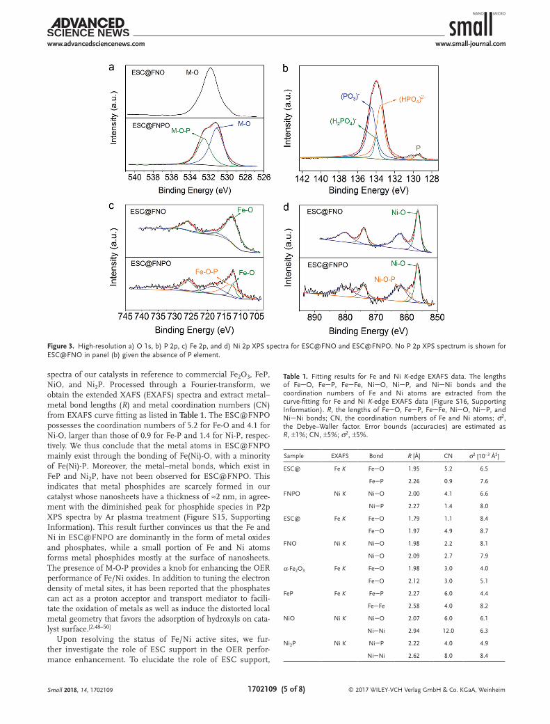
To collect the chemical information for ESC@FNPO, we employ high-resolution XPS by synchrotron radiation to ascer-tain the valence states of O, P, Fe, and Ni elements. The O1s XPS spectrum of ESC@FNPO (Figure 3a) can be split into two peaks − the one at 532.5 eV for M-O-P and the other at 531.2 eV
for M-O (M = Fe/Ni), while only one O1s peak is observed for ESC@FNO. Together with the XRD characterization (Figure S6, Supporting Information), this information identifies the forma-tion of Fe/Ni phosphates. We thus further characterize the P element in ESC@FNPO (Figure 3b). The P element indeed exists mainly in the form of phosphates according to the P2p XPS peaks at 134.6 eV for (PO3)−, 134.0 eV for (H2PO4)−, and 133.6 eV for (HPO4)2−.[43–45] Although there is a weak peak cor-responding to phosphide (129.3 eV),[46] this peak disappears after Ar plasma treatment (Figure S15, Supporting Informa-tion), indicating that the phosphide species is mainly located on surface. Meanwhile, the binding energies at 712.4 and 856.4 eV (Figure 3c,d), which are attributed to Fe 2p3/2 and Ni 2p3/2, respectively, suggest the form of Fe3+ and Ni2+ species in both ESC@FNO and ESC@FNPO.[5,47] There is no signifi-cant shift in Fe and Ni peaks between ESC@FNO and ESC@FNPO, except that a Fe(Ni)-O-P peak comes up in the spectra for ESC@FNPO. The information unambiguously reveals the formation of Fe/Ni phosphates—FeNi(POx)n.
To look into the local structures of Fe and Ni atoms, we fur-ther employ synchrotron radiation-based X-ray absorption fine structure (XAFS) spectroscopy to characterize ESC@FNO and ESC@FNPO. Figure S16 (Supporting Information) shows the Fe K-edge and Ni K-edge X-ray absorption near-edge structure
Small 2018, 14, 1702109
Figure 2. a) LSV curves and b) Tafel plots of ESC@FNPO, ESC@FNO (iron–nickel oxides on ESC without phosphatization) and ESC-P (bare ESC membrane treated with phosphatization) in reference to RuO2, collected on glassy carbon rotating disk electrodes (GC RDE) at the same total loading weight (40 µg) in 1 m KOH with iR-compensation. c) Durability test for ESC@FNPO. The inset shows a 24 h chronoamperometry. d) EIS Nyquist plots for ESC@FNO and ESC@FNPO conducted at an overpotential of 300 mV. The ESC@FNPO and ESC@FNO samples possess a Fe/Ni ratio of 1.
spectra of our catalysts in reference to commercial Fe2O3, FeP, NiO, and Ni2P. Processed through a Fourier-transform, we obtain the extended XAFS (EXAFS) spectra and extract metal–metal bond lengths (R) and metal coordination numbers (CN) from EXAFS curve fitting as listed in Table 1. The ESC@FNPO possesses the coordination numbers of 5.2 for Fe-O and 4.1 for Ni-O, larger than those of 0.9 for Fe-P and 1.4 for Ni-P, respec-tively. We thus conclude that the metal atoms in ESC@FNPO mainly exist through the bonding of Fe(Ni)-O, with a minority of Fe(Ni)-P. Moreover, the metal–metal bonds, which exist in FeP and Ni2P, have not been observed for ESC@FNPO. This indicates that metal phosphides are scarcely formed in our catalyst whose nanosheets have a thickness of ≈2 nm, in agree-ment with the diminished peak for phosphide species in P2p XPS spectra by Ar plasma treatment (Figure S15, Supporting Information). This result further convinces us that the Fe and Ni in ESC@FNPO are dominantly in the form of metal oxides and phosphates, while a small portion of Fe and Ni atoms forms metal phosphides mostly at the surface of nanosheets. The presence of M-O-P provides a knob for enhancing the OER performance of Fe/Ni oxides. In addition to tuning the electron density of metal sites, it has been reported that the phosphates can act as a proton acceptor and transport mediator to facili-tate the oxidation of metals as well as induce the distorted local metal geometry that favors the adsorption of hydroxyls on cata-lyst surface.[2,48–50]
Upon resolving the status of Fe/Ni active sites, we fur-ther investigate the role of ESC support in the OER perfor-mance enhancement. To elucidate the role of ESC support,
Small 2018, 14, 1702109
Figure 3. High-resolution a) O 1s, b) P 2p, c) Fe 2p, and d) Ni 2p XPS spectra for ESC@FNO and ESC@FNPO. No P 2p XPS spectrum is shown for ESC@FNO in panel (b) given the absence of P element.
Table 1. Fitting results for Fe and Ni K-edge EXAFS data. The lengths of FeO, FeP, FeFe, NiO, NiP, and NiNi bonds and the coordination numbers of Fe and Ni atoms are extracted from the curve-fitting for Fe and Ni K-edge EXAFS data (Figure S16, Supporting Information). R, the lengths of FeO, FeP, FeFe, NiO, NiP, and NiNi bonds; CN, the coordination numbers of Fe and Ni atoms; σ2, the Debye–Waller factor. Error bounds (accuracies) are estimated as R, ±1%; CN, ±5%; σ2, ±5%.
we compare the OER performance of our catalyst with the FeNi(POx)n nanosheet arrays supported on commercial carbon cloth (namely, CC@FNPO) (Figure S17, Supporting Infor-mation). As displayed in Figure 4a,b, CC@FNPO requires a higher overpotential of 370 mV to achieve a geometrical current density of 10 mA cm−2, and exhibits a larger Tafel slope of 47 mV dec−1. As compared with other supports, our ESC support mainly offers two merits: (1) nearly 100 times larger Brunauer–Emmett–Teller (BET) surface area than CC (Figure S18 and Table S3, Supporting Information), which offers larger interfacial area with Fe/Ni catalysts and more channels for species transportation; (2) remarkably lower charge-transfer resistance than CC (Figure 4c), which can be attributed to its high graphitization. To demonstrate the importance of graphitization to OER performance, we com-pare the LSVs between the nongraphitized ESC@FNPO (cal-cinated at 700 °C) and graphitized ESC@FNPO (calcinated at 900 °C) (Figure S19, Supporting Information), which possess comparable ESC surface area for growing active sites—FNPO. The nongraphitized ESC@FNPO exhibits an overpotential of 340 mV at j = 10 mA cm−2 and a Tafel slope of 41 mV dec−1, suggesting the lower performance than the graphitized ESC@FNPO. This further confirms that the graphitized ESC
supports make an important contribution to the performance improvement.
Another merit of ESC supports is that the form of mem-branes enables the implementation of ESC@FNPO and ESC@FNO as freestanding 3D electrodes. As demonstrated in Figure 4d, only an overpotential of 215 mV or 360 mV is applied to reach a geometrical current density of 10 mA cm−2 when a freestanding ESC@FNPO or ESC@FNO electrode is used, respectively. This performance exceeds almost all the documented values for counterpart electrocatalysts (Table S4, Supporting Information). The further enhanced performance, as compared with that on glassy carbon rotating disk electrode (GC RDE), indicates that the exclusion of polymer binder and glassy carbon electrode can boost the OER performance of cata-lysts. This enhancement should be ascribed to the improved species transportation, fully exposed 3D structures, and reduced resistance between electrode and catalyst. To deter-mine the Faradaic efficiency, we measure the amount of pro-duced O2 at a current of 40 mA by both oxygen sensor and gas chromatograph. As shown in Figure S20 (Supporting Informa-tion), the collected O2 volume is well fitted with the theoretical calculation for 100% Faradaic efficiency, demonstrating a high efficiency of our catalyst.
Small 2018, 14, 1702109
Figure 4. a) LSV curves and b) Tafel plots of ESC@FNPO and CC@FNPO (iron–nickel phosphate nanosheet arrays on carbon cloth) in 1 m KOH with iR-compensation. c) EIS Nyquist plots for bare carbon cloth (CC) and electrospun carbon nanofiber membrane (ESC) conducted at an overpotential of 500 mV. d) LSV curves of freestanding ESC@FNO and ESC@FNPO in 1 m KOH with iR-compensation. The FNPO and FNO possess a Fe/Ni ratio of 1.
In summary, we have developed an approach to freestanding graphitized carbon nanofiber supports, which enables the inte-gration with FeNi(POx)n nanosheet arrays with the improved interface and overcomes the existing limitation in OER applica-tion. Remarkably, the fabricated hybrid membrane can perfectly meet all the requirements for OER electrodes—the high activity and stability of catalysts, the high conductivity and stability of supports, the large area and intimate contact of their interfaces, and the easy transportation of O2 and ion species. As a result, the hybrid electrode exhibits excellent activity and durability in electrocatalytic OER, which stands out as one of the highest records as a non-noble metal OER system. As implemented as a freestanding electrode, the 3D hybrid structure achieves an overpotential down to 215 mV at 10 mA cm−2 in alkaline medium. The approach based on electrospinning offers the scalability for the production of polymer binder-free OER elec-trodes. From the fundamental perspective, we have employed synchrotron radiation-based spectroscopic techniques to establish the relationship between catalytic sites and OER performance. This work highlights the importance of ration-ally integrating active sites and supports to OER performance, which in principle can be extended to other electrocatalytic sys-tems and media by altering the grown catalytic materials. Thus, the concept demonstrated here provides an approach to low-cost and high-performance electrocatalytic materials.
4. Experimental SectionFabrication of ESC Nanofiber Membrane: The nanofiber membrane was
fabricated based on an electrospinning technique. In a typical process, 600 mg PAN was dissolved in 5 mL N,N-dimethylformamide (DMF). 1 mL DMF solution containing 0.3 m Co(CH3COO)2 was added into the PAN solution and stirred for 10 min. The mixture was then transferred to a 10 mL syringe for electrospinning. The electrospinning process was conducted under 15 kV with a 19 G needle. The injection rate was 1 mL h−1, and the distance between the needle and the collector was 12 cm. The electrospun PAN nanofiber membrane was dried in vacuum at 60 °C. The PAN membrane was cut into rectangular sheets and placed between two slices of quartz chips before high-temperature treatment. The high-temperature treatment was conducted at 900 °C with a rate of 5 °C min−1 in N2 atmosphere, which further transformed the PAN into carbon nanofiber membrane (namely, electrospun carbon).
Fabrication of ESC@FNO Hybrid Structure: Prior to electrodeposition, the thermal-treated ESC membrane was soaked in 1 m HNO3 for 10 h to remove surface cobalt species. In a typical electrodeposition procedure, a voltage of −1 V was applied to the ESC membrane as a working electrode in a three-electrode system. In the system, an aqueous solution containing 10 × 10−3 m Fe(NO3)3 and 10 × 10−3 m Ni(NO3)2 was used as an electrolyte, and a Pt foil and a Ag/AgCl electrode served as the counter electrode and reference electrode, respectively. After the electrodeposition for 10 min, the membrane product was washed with water and ethanol and dried in vacuum at 60 °C. The obtained membrane product was placed in a boat, treated at 300 °C with a ramping rate of 2 °C min−1 and kept for 2 h. Iron–nickel oxides (FNO) were formed at the ESC nanofiber membrane through the process above.
Fabrication of ESC@FNPO Hybrid Structure: The synthetic procedure for ESC@FNPO hybrid structure was similar to that for ESC@FNO, except the use of 400 mg NaH2PO2 during the thermal treatment at 300 °C. We placed The 400 mg NaH2PO2 was placed at the upstream side and the membrane sample at the downstream side in a N2 flow
in the same boat, which was treated at 300 °C with a ramping rate of 2 °C min−1 and kept for 2 h. This process transformed the iron–nickel compounds into FNPO at the ESC nanofiber membrane. To adjust the Fe/Ni ratios, the electrolytes containing different concentrations of Fe(NO3)3 and Ni(NO3)2 were used. Ar plasma treatment was performed with a reactive ion etching equipment by Ar flow at 4.0 Pa and 1 kV for different time.
Synchrotron-Radiation XPS Characterization: XPS spectra were collected at the Catalysis and Surface Physics Endstation at the BL11U beamline in the National Synchrotron Radiation Laboratory (NSRL) in Hefei, China. This beamline was connected to an undulator and equipped with two gratings that offer soft X-rays from 20 to 600 eV with a typical photon flux of 5 × 10¹⁰ photons s−1 and a resolution (E/ΔE) better than 105 at 29 eV. This system comprised of four ultrahigh vacuum chambers including analysis chamber, preparation chamber, molecular beam epitaxy (MBE) chamber, and a radial distribution chamber. The base pressures are 7 × 10⁻¹¹, 1 × 10⁻¹⁰, 5 × 10⁻¹⁰, and 2 × 10⁻¹¹ mbar, respectively. A sample load-lock system was connected to the sample transfer chamber. The analysis chamber was equipped with a VG Scienta R4000 analyzer, a monochromatic Al Kα X-ray source, a UV light source, low energy electron diffraction, a flood electron gun, and a manipulator with high precision and five-degree-of-freedom. The preparation chamber comprised an ion gun, a quartz crystal microbalance (QCM), a residual gas analyzer, a manipulator with high precision and four-degree-of-freedom, and several evaporators. The MBE chamber housed a QCM, several evaporators, and a manipulator with two-degree-of-freedom. With this radial distribution chamber, the time for each transfer process between two chambers is less than 1 min.
Synchrotron-Radiation XAFS Characterization: Ni and Fe K-edge XAFS measurements were performed at the beamline 14W1 in Shanghai Synchrotron Radiation Facility (SSRF), China. The X-ray was monochromatized by a double-crystal Si (111) monochromator. The storage ring of SSRF was operated at 3.5 GeV with the current of 300 mA. The acquired XAFS data were processed according to the standard procedures using the WinXAS3.1 program.[51] Theoretical amplitudes and phase-shift functions were calculated with the FEFF8.2 code using the crystal structural parameters of NiO, Fe2O3, Ni2P, and FeP.[52]
Supporting InformationSupporting Information is available from the Wiley Online Library or from the author.
AcknowledgementsThis work was financially supported in part by the NSFC (Grant Nos. 21471141, U1532135, 21573212, and 21601173), CAS Key Research Program of Frontier Sciences (Grant No. QYZDB-SSW-SLH018), CAS Interdisciplinary Innovation Team, Innovative Program of Development Foundation of Hefei Center for Physical Science and Technology (Grant No. 2016FXCX003), Recruitment Program of Global Experts, CAS Hundred Talent Program, and Anhui Provincial Natural Science Foundation (Grant Nos. 1608085QB24 and 1508085MB24). XAFS measurements were performed at the beamline BL14W1 in the Shanghai Synchrotron Radiation Facility (SSRF), China. XPS experiments were performed at the Catalysis and Surface Science Endstation in the National Synchrotron Radiation Laboratory (NSRL) in Hefei, China. The authors thank Dr. Huanxin Ju and Prof. Junfa Zhu for their help with XPS characterization.
Conflict of InterestThe authors declare no conflict of interest.
Received: June 21, 2017Revised: September 13, 2017
Published online: November 17, 2017
[1] F. Dionigi, P. Strasser, Adv. Energy Mater. 2016, 6, 1600621.[2] M. W. Kanan, D. G. Nocera, Science 2008, 321, 1072.[3] Z. W. Seh, J. Kibsgaard, C. F. Dickens, I. Chorkendorff, J. K. Nørskov,
T. F. Jaramillo, Science 2017, 355, 146.[4] J. S. Li, S. L. Li, Y. J. Tang, M. Han, Z. H. Dai, J. C. Bao, Y. Q. Lan,
Chem. Commun. 2015, 51, 2710.[5] C. Zhang, M. Shao, L. Zhou, Z. Li, K. Xiao, M. Wei, ACS Appl. Mater.
Interfaces 2016, 8, 33697.[6] S. Dou, C.-L. Dong, Z. Hu, Y.-C. Huang, J.-l. Chen, L. Tao, D. Yan,
D. Chen, S. Shen, S. Chou, S. Wang, Adv. Funct. Mater. 2017, 27, 1702546.
[7] C. Hu, L. Dai, Adv. Mater. 2017, 29, 1604942.[8] P. Cai, J. Huang, J. Chen, Z. Wen, Angew. Chem., Int. Ed. 2017, 56,
4858.[9] H. Shi, H. Liang, F. Ming, Z. Wang, Angew. Chem., Int. Ed. 2017, 56,
573.[10] X. Xiao, C.-T. He, S. Zhao, J. Li, W. Lin, Z. Yuan, Q. Zhang, S. Wang,
L. Dai, D. Yu, Energy Environ. Sci. 2017, 10, 893.[11] X. Lu, C. Zhao, Nat. Commun. 2015, 6, 6616.[12] X.-F. Lu, L.-F. Gu, J.-W. Wang, J.-X. Wu, P.-Q. Liao, G.-R. Li, Adv.
Mater. 2017, 29, 1604437.[13] M. Görlin, P. Chernev, J. F. de Araújo, T. Reier, S. Dresp, B. Paul,
R. Krähnert, H. Dau, P. Strasser, J. Am. Chem. Soc. 2016, 138, 5603.
[14] M. W. Louie, A. T. Bell, J. Am. Chem. Soc. 2013, 135, 12329.[15] C. C. L. McCrory, S. Jung, J. C. Peters, T. F. Jaramillo, J. Am. Chem.
Soc. 2013, 135, 16977.[16] Y. Qiu, L. Xin, W. Li, Langmuir 2014, 30, 7893.[17] R. D. L. Smith, M. S. Prévot, R. D. Fagan, Z. Zhang, P. A. Sedach,
M. K. J. Siu, S. Trudel, C. P. Berlinguette, Science 2013, 340, 60.[18] O. Diaz-Morales, I. Ledezma-Yanez, M. T. M. Koper, F. Calle-Vallejo,
ACS Catal. 2015, 5, 5380.[19] S. Chen, J. Duan, P. Bian, Y. Tang, R. Zheng, S. Z. Qiao, Adv. Energy
Mater. 2015, 5, 1500936.[20] M. Gong, Y. Li, H. Wang, Y. Liang, J. Z. Wu, J. Zhou, J. Wang,
T. Regier, F. Wei, H. Dai, J. Am. Chem. Soc. 2013, 135, 8452.[21] L. Trotochaud, S. L. Young, J. K. Ranney, S. W. Boettcher, J. Am.
Chem. Soc. 2014, 136, 6744.[22] D. Friebel, M. W. Louie, M. Bajdich, K. E. Sanwald, Y. Cai,
A. M. Wise, M.-J. Cheng, D. Sokaras, T.-C. Weng, R. Alonso-Mori, R. C. Davis, J. R. Bargar, J. K. Nørskov, A. Nilsson, A. T. Bell, J. Am. Chem. Soc. 2015, 137, 1305.
[23] C. G. Morales-Guio, L. Liardet, X. Hu, J. Am. Chem. Soc. 2016, 138, 8946.
[24] Y. Wang, Y. Zhang, Z. Liu, C. Xie, S. Feng, D. Liu, M. Shao, S. Wang, Angew. Chem., Int. Ed. 2017, 56, 5867.
[25] R. Liu, Y. Wang, D. Liu, Y. Zou, S. Wang, Adv. Mater. 2017, 29, 1701546.
[26] C. Tang, N. Cheng, Z. Pu, W. Xing, X. Sun, Angew. Chem., Int. Ed. 2015, 54, 9351.
[27] X. Xu, F. Song, X. Hu, Nat. Commun. 2016, 7, 12324.[28] M. Ledendecker, S. K. Calderón, C. Papp, H. P. Steinrück,
M. Antonietti, Angew. Chem., Int. Ed. 2015, 54, 12361.[29] L. A. Stern, L. Feng, F. Song, X. Hu, Energy Environ. Sci. 2015, 8,
2347.[30] T. Zhang, J. Du, P. Xi, C. Xu, ACS Appl. Mater. Interfaces 2017, 9,
362.[31] C. Wang, J. Jiang, T. Ding, G. Chen, W. Xu, Q. Yang, Adv. Mater.
Interfaces 2016, 3, 1500454.[32] D. Xiong, X. Wang, W. Li, L. Liu, Chem. Commun. 2016, 52, 8711.[33] Z. Zhang, J. Hao, W. Yang, J. Tang, RSC Adv. 2016, 6, 9647.[34] Y. Zhan, M. H. Lu, S. L. Yang, Z. L. Liu, J. Y. Lee, ChemElectroChem
2016, 3, 615.[35] Y. Li, C. Zhao, Chem. Mater. 2016, 28, 5659.[36] Y. F. Zhao, S. Q. Chen, B. Sun, D. W. Su, X. D. Huang, H. Liu,
Y. M. Yan, K. N. Sun, G. X. Wang, Sci. Rep. 2015, 5, 7629.[37] L. Jiao, Y.-X. Zhou, H.-L. Jiang, Chem. Sci. 2016, 7, 1690.[38] M.-S. Balogun, W. Qiu, H. Yang, W. Fan, Y. Huang, P. Fang, G. Li,
H. Ji, Y. Tong, Energy Environ. Sci. 2016, 9, 3411.[39] C. Kim, K. S. Yang, M. Kojima, K. Yoshida, Y. J. Kim, Y. A. Kim,
M. Endo, Adv. Funct. Mater. 2006, 16, 2393.[40] C. Zhu, X. Mu, P. A. van Aken, Y. Yu, J. Maier, Angew. Chem., Int. Ed.
2014, 53, 2152.[41] J. Shui, C. Chen, L. Grabstanowicz, D. Zhao, D.-J. Liu, Proc. Natl.
Acad. Sci. USA 2015, 112, 10629.[42] C. Kim, Y. I. Jeong, B. T. N. Ngoc, K. S. Yang, M. Kojima, Y. A. Kim,
M. Endo, J.-W. Lee, Small 2007, 3, 91.[43] T. Zhai, L. Wan, S. Sun, Q. Chen, J. Sun, Q. Xia, H. Xia, Adv. Mater.


![Scalable fabrication of organic solar cells based on non ... · fullerene-free active layers are exhibiting efficiencies above7%[33,34],which,coupledwithrecentreports of 10 year](https://static.documents.pub/doc/80x56/5f414403ccd47957c63bba3d/scalable-fabrication-of-organic-solar-cells-based-on-non-fullerene-free-active.jpg)


