17
NATIONAL CONTROL DEVICES SCAN Series Quick Start Guide Contact Closure Input Commands Enhanced Version

NATIONAL CONTROL DEVICES SCAN Series Quick Start Guide
Contact Closure Input Commands Enhanced Version

N A T I O N A L C O N T R O L D E V I C E S
SCAN Series
Contact Closure Input Commands Enhanced Version
National Control Devices, LLC PO Box 455
Osceola, MO 64776 Phone 417.646.5644 • Fax (866) 562-0406
© Copyright 2013 All Rights Reserved.
Notice: Portions of this manual require internet access.

Table of Contents
Introduction .............................................................................. 1
Getting Started .......................................................................................... 1
SCAN Series Hardware ............................................................ 2
Base Station Software .............................................................. 8
Standard Version Command Set ............................................ 10
Command Set—Standard Version ......................................................... 10
Command Set—Enhanced Version ........................................................ 11
Technical Support ..................... Error! Bookmark not defined.
Contact Information .......................... Error! Bookmark not defined.
Notice: ....................................................... Error! Bookmark not defined.

1
Notice:
All inputs labeled “A” are GROUND inputs, and all inputs labeled “B” are Contact Closure Inputs.
Never apply a Voltage to any contact closure input with consulting a NCD Engineer.
Introduction
CD Devices with Contact Closure Input monitoring capabilities will use this command set to read no less than 8 contact closure inputs with a single
query. This includes the ZSCAN series controllers and any NCD Devices equipped with a UXP Expansion Port and a USCS16, USCS32, or USCS48 contact closure input expansion board.
This SCAN Series command set allows the user to read anywhere from 1 to 32 banks of 8 inputs in a single query. A single bank contains 8 inputs. Reading 32 banks will report the status of 256 inputs.
This command has been enhanced to report more than one bank. Original ProXR Standard controllers are only capable of reading one bank of 8 inputs per query. The enhanced version allows you to include an optional parameter to read the selected bank plus 1 to 31 additional banks for a total of 32 banks per query.
Getting Started
Please refer to the hardware diagram for connecting your contact closure input device.
N

2
SCAN Series Hardware
Ultra Series ScanSwitch 16-Channel Contact Closure Detector Expansion Module (USCS16)
NOTE:
All Inputs Labeled “A” are GROUND Inputs.
All Inputs Labeled “B” are Contact Closure Inputs.
NEVER APPLY A VOLTAGE TO ANY CONTACT CLOSURE INPUT WITHOUT CONSULTING A NCD ENGINEER!

3
Ultra Series ScanSwitch 32-Channel Contact Closure Detector Expansion Module (USCS32)
NOTE:
All Inputs Labeled “A” are GROUND Inputs.
All Inputs Labeled “B” are Contact Closure Inputs.
NEVER APPLY A VOLTAGE TO ANY CONTACT CLOSURE INPUT WITHOUT CONSULTING A NCD ENGINEER!
4
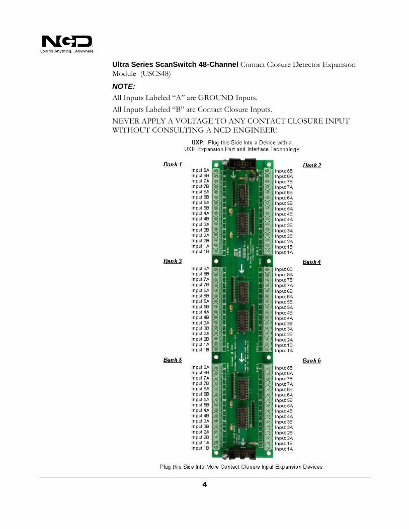
Ultra Series ScanSwitch 48-Channel Contact Closure Detector Expansion Module (USCS48)
NOTE:
All Inputs Labeled “A” are GROUND Inputs.
All Inputs Labeled “B” are Contact Closure Inputs.
NEVER APPLY A VOLTAGE TO ANY CONTACT CLOSURE INPUT WITHOUT CONSULTING A NCD ENGINEER!

5
USB 16-Channel Contact Closure Input Scanner Detector (ZSCAN16PROXR_USB)
NOTE:
All Inputs Labeled “A” are GROUND Inputs.
All Inputs Labeled “B” are Contact Closure Inputs.
NEVER APPLY A VOLTAGE TO ANY CONTACT CLOSURE INPUT WITHOUT CONSULTING A NCD ENGINEER!

6
USB 32-Channel Contact Closure Input Scanner Detector (ZSCAN32PROXR_USB)
NOTE:
All Inputs Labeled “A” are GROUND Inputs.
All Inputs Labeled “B” are Contact Closure Inputs.
NEVER APPLY A VOLTAGE TO ANY CONTACT CLOSURE INPUT WITHOUT CONSULTING A NCD ENGINEER!

7
USB 48-Channel Contact Closure Input Scanner Detector (ZSCAN48PROXR_USB)
NOTE:
All Inputs Labeled “A” are GROUND Inputs. All Inputs Labeled “B” are Contact Closure Inputs.
NEVER APPLY A VOLTAGE TO ANY CONTACT CLOSURE INPUT WITHOUT CONSULTING A NCD ENGINEER!

8
Base Station Software
Introduction
NCD Devices with Contact Closure Input monitoring will use this command set to read no less than 8 contact closure inputs with a single query. This includes the ZSCAN series controllers and any NCD Devices equipped with a UXP Expansion Port and a USCS16, USCS32, USCS48 contact closure input expansion board.
A single bank contains 8 inputs. All SCAN Series Devices are capable of Reading Banks 0 through 255 for a total of 256 firmware supported input banks (2048 total supported inputs).
This command has been enhanced to report more than one bank. Original Pro XR Standard controllers are only capable of reading one bank of 8 inputs per query. The enhanced version allows you to include an optional parameter to read the selected bank plus 1 to 31 additional banks for a total of 32 banks per query.
Base station Software
Run the NCD Base Station software to communicate with your SCAN Series controller. After connecting the controller to your computer, select the correct port or IP Address for your controller. You will see the dialog box shown in the screen shot below. Select ‘UXP SCAN Series Contact Closure Input Command Set’
as selected below.
9
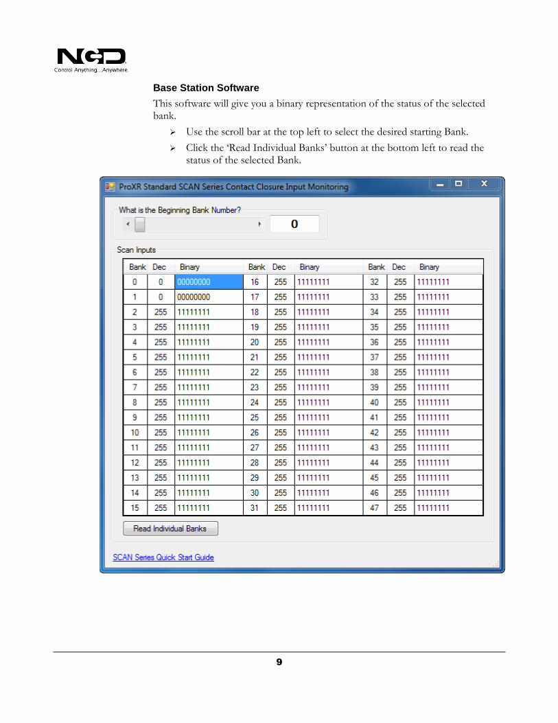
Base Station Software
This software will give you a binary representation of the status of the selected bank.
Use the scroll bar at the top left to select the desired starting Bank.
Click the ‘Read Individual Banks’ button at the bottom left to read the status of the selected Bank.

10
Standard Version Command Set
Command Set—Standard Version
Read Single Bank
This command reads a single bank of inputs and reports a value from 0 to 255 indicating the status of 8 inputs in the selected bank. An optional parameter may be included to read from 1 to 31 additional banks for a maximum of 32 banks per query.
Send Bytes: Byte 1: Byte 2: Byte 3:
Function: Command Bank
Decimal Values: 254 175 0-255
Hex Values 0xFE 0xAF 0x00-0xFF
Receive Byte: Decimal: 0-255 (Up to 32 Bytes will be sent)
Hex: 0x00-0xFF
COMM Operator Examples:
254 175 0 Device Reads the First 8 Contact Closure Inputs and Returns a Value of 0-255
The controller will report the status of 8 inputs as a single byte of data. The following software method should be used to determine which inputs are actually high and low (Value = Byte Received from Controller; the "AND" function is a software function supported by most programming languages):
If Value AND 1 = 1 then Bit 0 is ON
If Value AND 2 = 2 then Bit 1 is ON
If Value AND 4 = 4 then Bit 2 is ON
If Value AND 8 = 8 then Bit 3 is ON
If Value AND 16 = 16 then Bit 4 is ON
If Value AND 32 = 32 then Bit 5 is ON
If Value AND 64 = 64 then Bit 6 is ON
If Value AND 128 = 128 then Bit 7 is ON
Or you can do combinations to test multiple bits:
If Value AND 3 = 3 then Bits 0 and 1 are ON
If Value AND 129 = 129 then Bits 0 and 7 are ON
If Value AND 7 = 7 then Bits 0, 1, and 2 are ON
If Value AND 255 = 255 then All Bits are ON

11
Command Set—Enhanced Version
Read Single Bank
This command reads a single bank of inputs and reports a value from 0 to 255 indicating the status of 8 inputs in the selected bank. An optional parameter may be included to read from 1 to 31 additional banks for a maximum of 32 banks per query.
Send Bytes: Byte 1: Byte 2: Byte 3: Byte 4: Function: Command Bank More
Decimal Values: 254 175 0-255 1-31
Hex Values 0xFE 0xAF 0x00-0xFF 0x
Receive Byte: Decimal: 0-255 (Up to 32 Bytes will be sent)
Hex: 0x00-0xFF
COMM Operator Examples:
Read 1 Byte:
254 175 0 Device Reads the First 8 Contact Closure Inputs and Returns a Value of 0-255
Read 3 Bytes:
254 175 0 2 Device Read the First Bank Plus 2 More Banks and Returns 3 Bytes
Read 5 Bytes:
254 175 5 4 Device Reads Bank 5 Plus 4 More Banks (6, 7, 8, and 9) and Returns 5 Bytes
The controller will report the status of 8 inputs as a single byte of data. The following software method should be used to determine which inputs are actually high and low (Value = Byte Received from Controller; the "AND" function is a software function supported by most programming languages):
If Value AND 1 = 1 then Bit 0 is ON
If Value AND 2 = 2 then Bit 1 is ON
If Value AND 4 = 4 then Bit 2 is ON
If Value AND 8 = 8 then Bit 3 is ON
If Value AND 16 = 16 then Bit 4 is ON
If Value AND 32 = 32 then Bit 5 is ON
If Value AND 64 = 64 then Bit 6 is ON
If Value AND 128 = 128 then Bit 7 is ON
Or you can do combinations to test multiple bits:
If Value AND 3 = 3 then Bits 0 and 1 are ON
If Value AND 129 = 129 then Bits 0 and 7 are ON
If Value AND 7 = 7 then Bits 0, 1, and 2 are ON
If Value AND 255 = 255 then All Bits are ON

12
NCD Base Station Software
Use the ‘UXP SCAN Quality Control and Diagnostics’ to help identify problems with the controller.
Select the appropriate number of inputs and begin testing by moving the program/run jumper to both positions. Once this test has passed, communication speed will increase (which makes testing a little faster). Next, connect a jumper wire to each input individually until you see PASS for each input. If a failure is detected, the corresponding input failures will be identified. If a failure is discovered, the device must be returned to NCD for repair services.

13
Technical Support
echnical support is available through our website, controlanything.com. Support is the way we connect NCD engineers to our customers.
Click on the Support tab at the top of any page on our website to be taken to the Forum page. Here you can publicly post or review problems that customers have had, and learn about our recommended solutions.
Our engineers monitor questions and respond continually throughout the day. Before requesting telephone technical support, we ask that customers please try to resolve their problems through Support first. However, for persistent problems, NCD technical support engineers will schedule a phone consultation.
T

14
Contact Information
National Control Devices, LLC PO Box 455 Osceola, MO 64776 417-646-5644 phone 866-562-0406 fax Open 9 a.m. - 4 p.m. CST Like “National Control Devices” on Facebook, and follow us on Twitter @ControlAnything. All orders must be placed online at our website, www.controlanything.com
Notice:
The only authorized resellers of NCD products are
www.controlanything.com
www.relaycontrollers.com
www.relaypros.com
All other websites are not authorized dealers; we have noticed some retailers offering our products fraudulently.
Copyright © 2013 National Control Devices
All Rights Reserved.


