43
Scanning Multiple Projection Digital Image Processo r Stroboscop e Through 2D Recording Through 3D Recording Paths to 3D PIV Holography
| Date post: | 22-Dec-2015 |
| Category: |
Documents |
| View: | 227 times |
| Download: | 1 times |
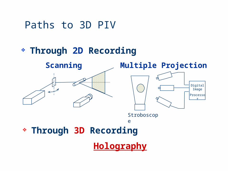
Scanning Multiple Projection
Digital Image
Processor
Stroboscope
Through 2D Recording
Through 3D Recording
Paths to 3D PIV
Holography

Principle of HPIV
DisplacementVelocity
Holocine (time resolved)
t1 t2 t3
Hologram
8ns
LaserPulse
3D flow seeded with particles
Recording
CCD
Interrogationcamera
Laser Beam
Reconstruction
Double Exposure
t1 t1+ t t2 t2+ t

Advantage of holography
True 3D imaging Instantaneous Volumetric High Information Capacity
(106 - 109 Particles)Real-Time Recording but Off-line Data Transfer
& Processing

How to get true 3D imaging?
Phase Preservation
O=Oexp[i(-t)] or: O=Osin(t)
How to record ?
Any light sensitive media records intensity I=|O|2 =O2
Need to “encode” phase into some intensity modulation
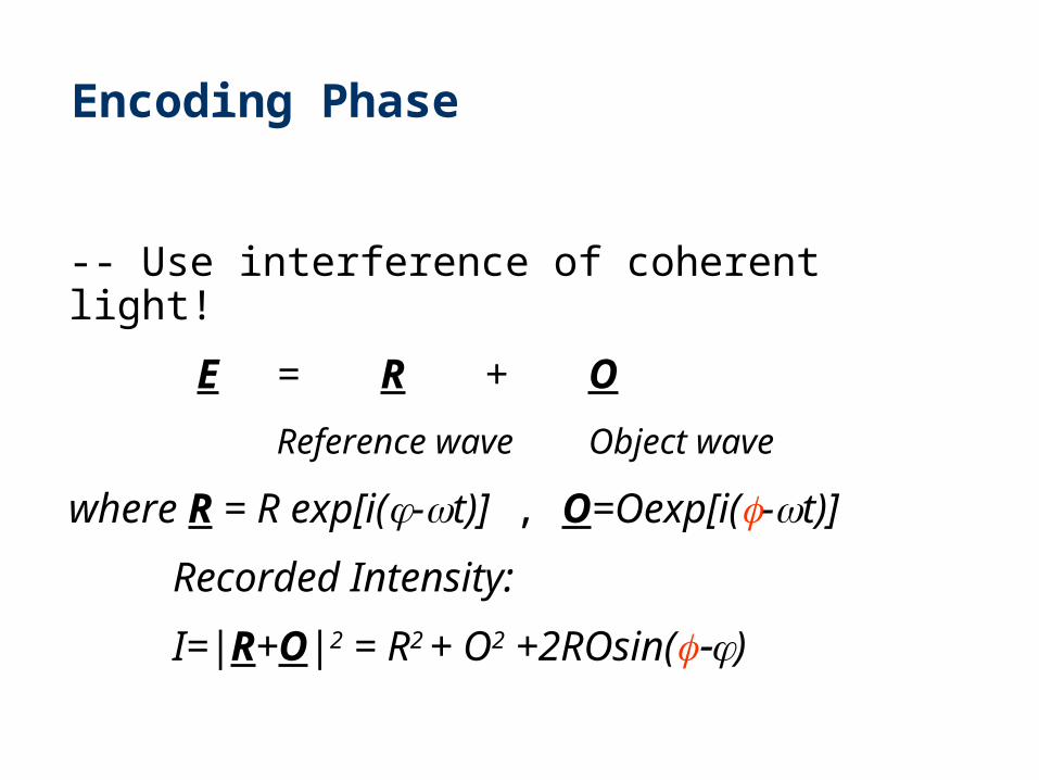
Encoding Phase
-- Use interference of coherent light!
E = R + O
Reference wave Object wave
where R = R exp[i(-t)] , O=Oexp[i(-t)]
Recorded Intensity:
I=|R+O|2 = R2 + O2 +2ROsin()
Real Image
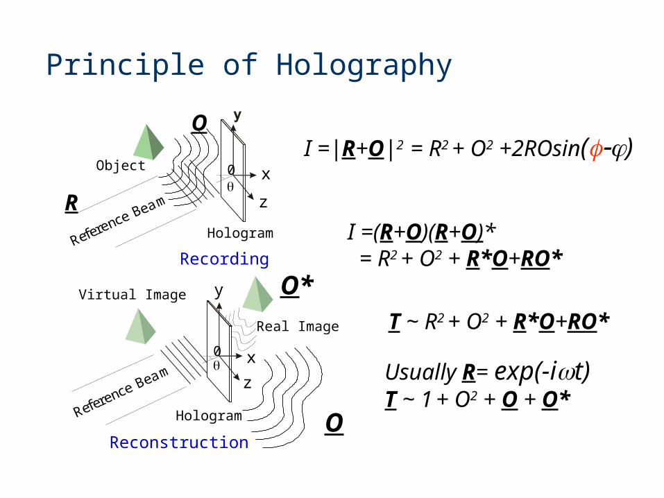
Principle of Holography
Reference Beam
Virtual Image
x
z
Hologram
0
RecordingReference Beam
Reconstruction
y
x
z
Hologram
0
ObjectI =|R+O|2 = R2 + O2 +2ROsin()
R
O
O
I =(R+O)(R+O)* = R2 + O2 + R*O+RO*
O*T ~ R2 + O2 + R*O+RO*
Usually R= exp(-it) T ~ 1 + O2 + O + O*

Experimental Demonstration
Reference beam, object beamVirtual, real image*Transmission or Reflection Hologram?
Setup Considerations:
Coherence length vs. path length difference
Exposure energy: In the linear range
R:O ratio
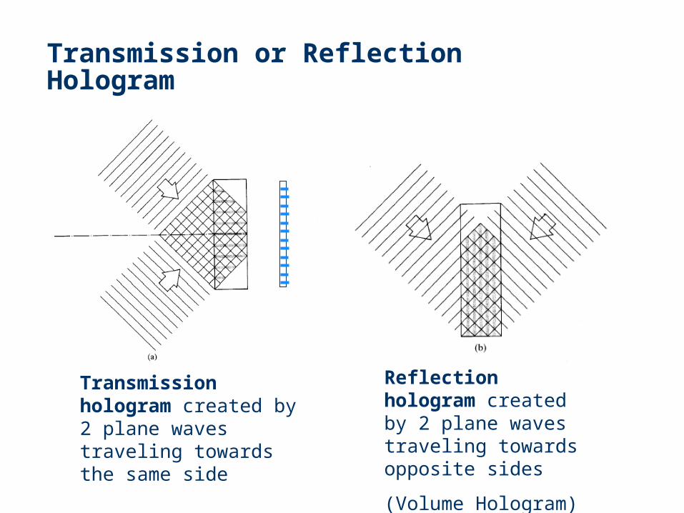
Transmission or Reflection Hologram
Transmission hologram created by 2 plane waves traveling towards the same side
Reflection hologram created by 2 plane waves traveling towards opposite sides
(Volume Hologram)

Reflection Hologram
Bragg Condition2dsin=m
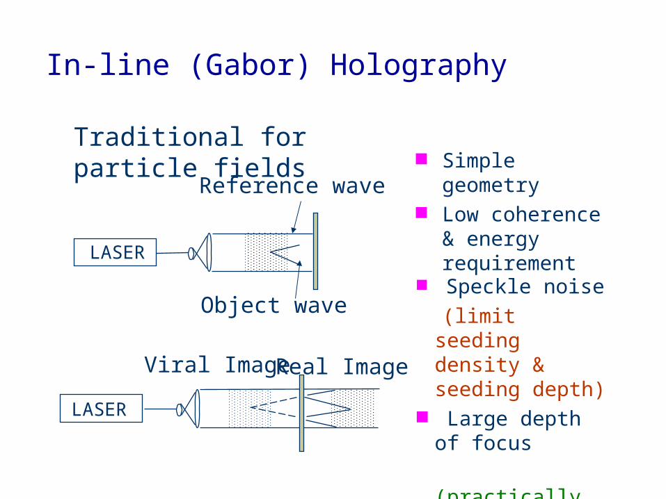
In-line (Gabor) Holography
Simple geometry Low coherence &
energy requirement
Traditional for particle fields
Speckle noise
(limit seeding density & seeding depth)
Large depth of focus
(practically only 2D vectors)
Reference wave
Object wave
LASER
LASER
Real ImageViral Image

Speckle Noise (in-line hologram)
Reconstruction field of an in-line hologram for an ensemble of particles: B + ok+ o*k
Type-I speckle -- interference between B and the scattered waves Major Source of SpeckleType-II speckle -- self-interference of the scattered waves.
Ok = ok= kexp(ik) : Random Walk
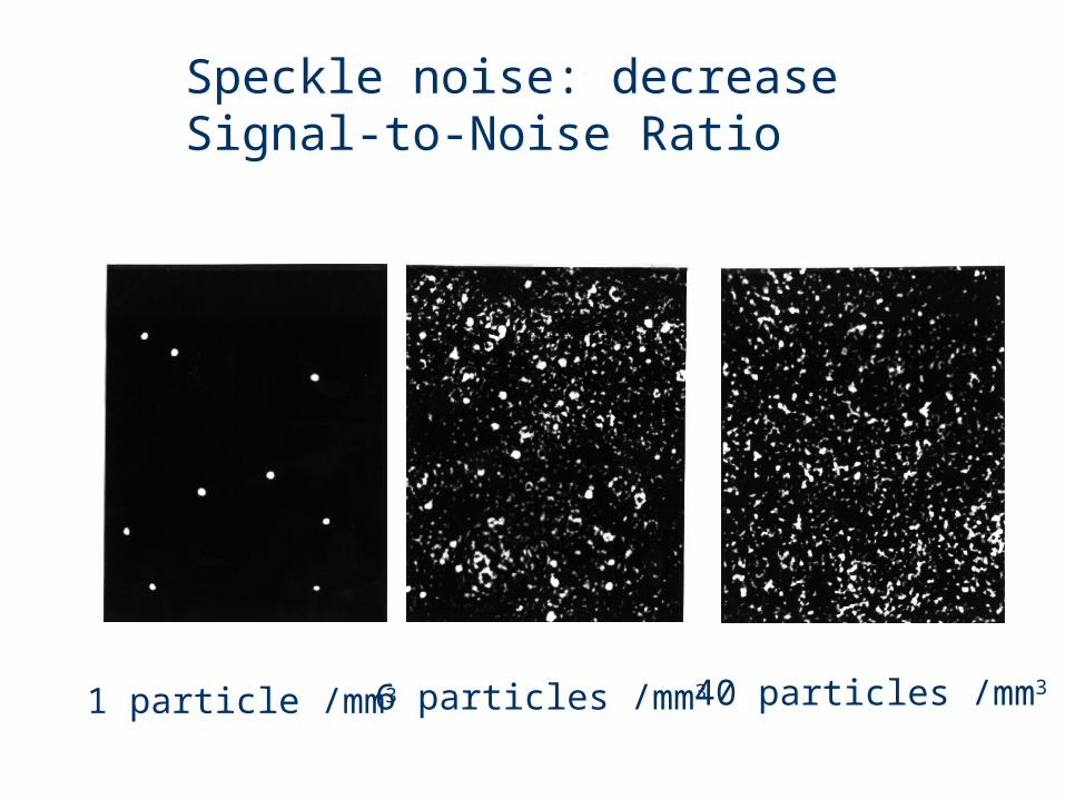
Speckle noise: decrease Signal-to-Noise Ratio
1 particle /mm3 6 particles /mm3 40 particles /mm3

Off-Axis Holography as Solution
Off-axis HPIV:Higher SNRHigher Seeding Density
Complex GeometryHigher Coherence Required
Reconstruction
VirtualImage
RealImage
Hologram
ReferenceBeam
Hologram
IlluminatingBeam
ReferenceBeam
Recording
Off-axis HPIV
Reconstruction
VirtualImage
RealImage
Hologram Hologram
ReferenceBeam
ReferenceBeam
In-line HPIV
Recording
In-Line HPIV:Simple GeometryLower Coherence Required
Intrinsic Speckle NoiseLower Seeding Density

IROV In-line Recording Off-axis Viewing Holography
IROV: Use side scattering Suppresses speckle noise Reduces image depth of focus
Making In-line based HPIV feasible
Ho lo g ra mVirtua lIm a g e
Ho lo g ra mRe a lIm a g e
Re c o rd ing Re c o nstruc tio n
Re fe re nc eBe a m
Re fe re nc eBe a m
C o nve ntio na lIn-line
IRO V
Meng & Hussain (1995): Appl. Opt. 34, 1827

Recording Reconstruction
IROV Experimental SetupIROV Experimental Setup

Use of High-Frequency Fringes on In-Line Holograms
Negligible influence of forward scattering: Since |OL| << |R|, IL << I sig
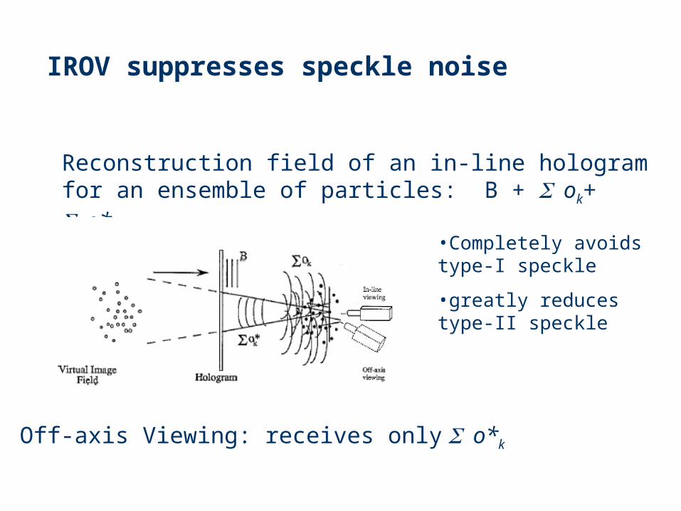
IROV suppresses speckle noise
•Completely avoids type-I speckle
•greatly reduces type-II speckle
Reconstruction field of an in-line hologram for an ensemble of particles: B + ok+ o*k
Off-axis Viewing: receives only o*k
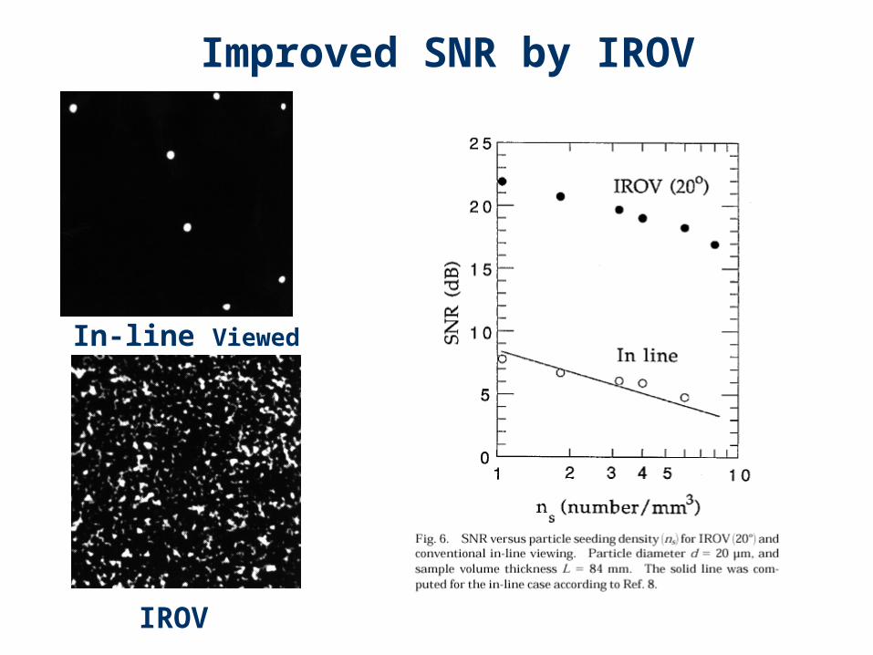
Improved SNR by IROV
IROV
In-line Viewed

Reduction of Depth of Focus by IROV
0 degree 20 degree
In focus
+100 m
-100 m
In-line: Fraunhofer diffraction

Proof of Principle Experiment
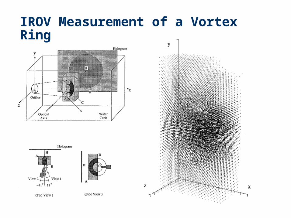
IROV Measurement of a Vortex Ring

Post Processing

Low density requires intelligent pairing
GA searches large solution space
IROV Data Processing: Genetic Algorithm Particle Pairing
2’
1’
3’
4’
5’
6’
7’1
2
34
5
67
Interrogation Cell 3
12
,,, RzyxPtt
PPV i
iiii

Genetic Algorithm Particle Pairing

Why Genetic Algorithm?
Many possibilities to pair particles Need to numerate and filter
Conventional searching methods
Computation intensive Difficult to incorporate
intelligence Time consuming
Genetic Algorithm Efficient in searching large space Built-in intelligence to follow fluid
dynamics Fast and inherent parallel processing
speed
Large solution space

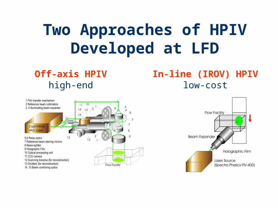
Two Approaches of HPIVDeveloped at LFD
Off-axis HPIVhigh-end
In-line (IROV) HPIVlow-cost
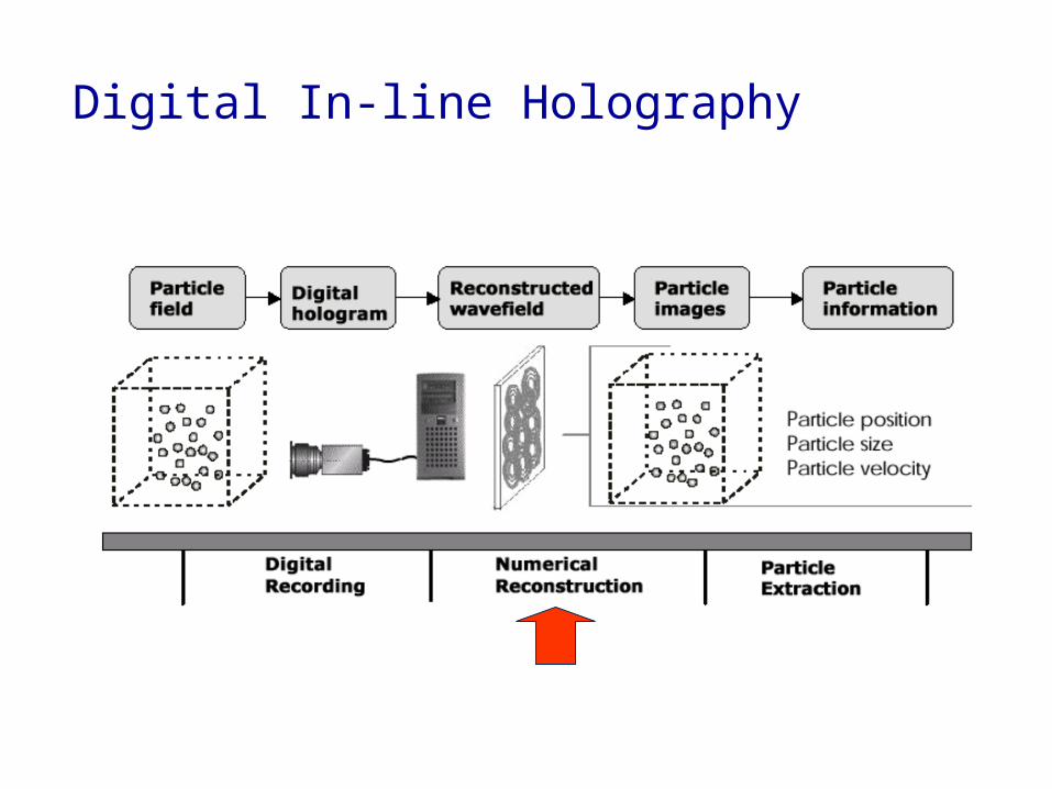
Digital In-line Holography

Dual-Reference Off-Axis TechniqueDual-Reference Off-Axis Technique
High Seeding Density AllowedSmall Depth of FocusImage Separation Removes Direction Ambiguity
Complex Optical GeometryHigh Energy Laser RequiredHigh Coherence of Beam Needed

Beam Expander
Be
am
Ex
pa
nd
er
B eam Expander
Beam Handling U nit
Variable B eam Splitter
Referenc e 1
Referenc e 2
M irror
M irror
Dumper
H EM
H EM
H EM
H EM H EM H EM H EM
H EM
H EMP
BS
PB
S
B SBS
WP WP
Sh
utt
er
1
Sh
utt
er
2
Pa
rtic
leF
ield
(Vo
rte
x)
I l luminating B eam
H olographic Exposure U nit
Sy
nc
hro
niz
er
Digita lDelayGenerator
Ho
log
ram
Dual Seeded YAGL aser (P IV-400)
Beam Expander
Beam Expander
Beam Handling U nit
Variable B eam Splitter
Referenc e 1
Referenc e 2
M irror
M irror
H EM
H EM
H EM H EM H EM H EM
H EM
H EM
PB
S
PB
S
B SBS
WP WP
Sh
utt
er
1
Sh
utt
er
2
Rec onstruc tedPar tic leImage
I lluminating B eam
H olographic Rec onstruc tionU nit
Dumper
Digita lCamera
3D Travers eSystem
200M HzPentium P roP roc ess or
64M BM emory
Digita l ImageFramegrabber
H ardDis k
P C I Bus
M otionContro ller
M otorDriver
Dual Seeded YAGL aser (P IV-400)
Gemini Off-axis HPIV System

Concise Cross Correlation(CCC) Algorithm
Matching by particle groups Uses particle centroids only Group shifting for matching Decomposition of operation Low data volume / high
compression rate High-speed processing

System Test FlowExcited Air Jet
P ow erA mplifi er
P L LFrequenc yM ult iplier
VaiableDelayer
WaveformShaper
Vor tex Sync hronizer
Droplet-s eededInjec tion A ir F low
Digital DelayGenerator
Beam E xpander
Objec tBeam
Speaker/E xc iter
Vor tex
Dual SeededYA G L as er(P IV-400)

Phase-Locked Vortex
Side View Top View

Vorticity

Vorticity Iso-surface
To be re-made

HPIV Measurement of Tab Wake

Vortab Flow: HPIV Measurement Result
Amount of Data: 400,000 Vectors
Mean Velocity: 16.67 cm/sec.

Vortab Flow: Vorticity Iso-Surfaces
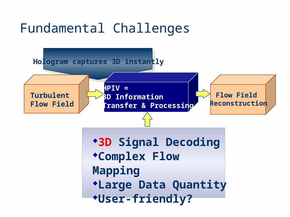
Hologram captures 3D instantly
TurbulentFlow Field
HPIV = 3D InformationTransfer & Processing
Fundamental Challenges
3D Signal DecodingComplex Flow MappingLarge Data QuantityUser-friendly?
Flow Field Reconstruction

Holographic Flow Visualization
a Tool for Studying 3D Coherent Structures and Instabilities
Kansas State University, ISSI,Wright Laboratory, WP/AFB

d
(a) (b) (c)
Holographic Images of Three Vortex-Flame Systems Photographed from Two Angles (a) or Using Two Magnifications (b and c).
Off-Axis HFV of Vortex Flame
b ca
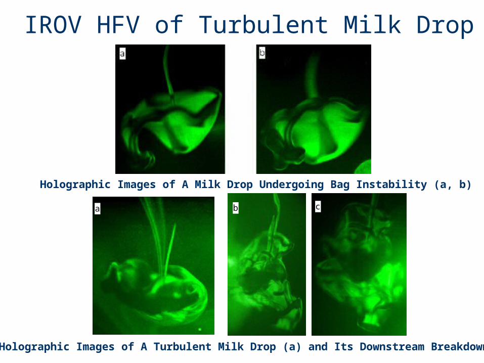
Holographic Images of A Milk Drop Undergoing Bag Instability (a, b)
Holographic Images of A Turbulent Milk Drop (a) and Its Downstream Breakdown (b, c)
IROV HFV of Turbulent Milk Drop

Naturally, HPIV is an ideal diagnostic tool for studying particulate phase
3D and dynamically


