Page 1
A.S0012-0v1.0
3GPP2 A.S0012-0
Version 1.0
Date: November 16, 2001
1
2
3
4
5
6
7
8
9
10
11
12
Interoperability Specification (IOS) for CDMA 2000 13
Access Network Interfaces — Part 2 Transport 14
15
Revision 0 (3G IOSv4.2) 16
17
(SDO Ballot Version) 18
19
20
21
22
23
24
25
26
© 3GPP2 2001 27
3GPP2 and its Organizational Partners claim copyright in this document and individual 28
Organizational Partners may copyright and issue documents or standards publications in 29
individual Organizational Partner's name based on this document. Requests for reproduction of 30
this document should be directed to the 3GPP2 Secretariat at [email protected] . Requests 31
to reproduce individual Organizational Partner's documents should be directed to that 32
Organizational Partner. See www.3gpp2.org for more information. 33
34
Page 3
A.S0012-0v1.0
i
Table of Contents 1
2
1.0 Introduction......................................................................................................................................... 1 3
1.1 Overview......................................................................................................................................... 1 4
1.1.1 Purpose.................................................................................................................................... 1 5
1.1.2 Scope....................................................................................................................................... 1 6
1.2 References....................................................................................................................................... 1 7
1.2.1 Telecommunications Industry Association (TIA) / Electronics 8
Industry Association (EIA) ..................................................................................................................... 2 9
1.2.2 3GPP2 ..................................................................................................................................... 2 10
1.2.3 Standards Committee T1......................................................................................................... 2 11
1.2.4 International Telecommunications Union - Telecommunications Sector (ITU-T) ................. 2 12
1.2.5 Other ....................................................................................................................................... 3 13
1.3 Terminology.................................................................................................................................... 3 14
1.3.1 Acronyms................................................................................................................................ 3 15
1.3.2 Definitions............................................................................................................................... 6 16
2.0 Network and Transport Protocols ....................................................................................................... 7 17
2.1 Signaling Connection Transport Protocol Options ......................................................................... 7 18
2.2 User Traffic Connection Transport Protocol Options ..................................................................... 8 19
3.0 Physical Layer Specification (Layer 1)............................................................................................. 11 20
4.0 Use of ANSI SS7 Transport (Layer 2).............................................................................................. 13 21
4.1 Field of Application ...................................................................................................................... 13 22
4.2 Message Transfer Part................................................................................................................... 14 23
4.2.1 General.................................................................................................................................. 14 24
4.2.2 Level 1 (T1.111.2) ................................................................................................................ 14 25
4.2.3 Level 2 (T1.111.3) ................................................................................................................ 14 26
4.2.4 Level 3 (T1.111.4) ................................................................................................................ 15 27
4.2.5 Testing and Maintenance (T1.111.7) .................................................................................... 17 28
4.2.6 Interface Functions................................................................................................................ 17 29
4.2.7 Overload Control (Message Throughput Congestion) .......................................................... 17 30
4.3 SCCP Transport Layer Specification (SCCP Functions) .............................................................. 18 31
4.3.1 Overview............................................................................................................................... 18 32
4.3.2 Primitives (T1.112.1) ............................................................................................................ 18 33
4.3.3 SCCP Messages (T1.112.2) .................................................................................................. 19 34
4.3.4 SCCP Formats and Codes (T1.112.3) ................................................................................... 21 35
4.3.5 SCCP Procedures (T1.112.4) ................................................................................................ 21 36
4.4 Use of the SCCP ........................................................................................................................... 23 37
4.4.1 The Direct Transfer Application Part.................................................................................... 23 38
4.4.2 The BS Management Application Part.................................................................................. 23 39
4.4.3 Connection Establishment..................................................................................................... 24 40
4.4.3.1 Establishment Procedure - Case 1..................................................................................... 24 41
4.4.3.2 Establishment Procedure - Case 2..................................................................................... 25 42
4.4.4 Connection Release............................................................................................................... 26 43
4.4.5 Abnormal SCCP Release ...................................................................................................... 27 44
4.4.5.1 SCCP Release by BS: Loss of SCCP Connection Information......................................... 27 45
4.4.5.2 SCCP Release by MSC: Loss of SCCP Connection Information ..................................... 28 46
4.4.6 SCCP Reference Generation Philosophy .............................................................................. 29 47
4.4.7 SCCP Transfer of DTAP and BSMAP Messages ................................................................. 29 48
5.0 Use of ATM (Layer 2) ...................................................................................................................... 35 49
5.1 Field of Application ...................................................................................................................... 35 50
5.2 ATM Layer ................................................................................................................................... 35 51
5.3 ATM Adaptation Layer................................................................................................................. 35 52
5.4 Use of ATM AAL5 for Transmission of IP Datagrams ................................................................ 36 53
6.0 TCP Transport Protocol Usage ......................................................................................................... 37 54
6.1 General Use of TCP ...................................................................................................................... 37 55
Page 4
A.S0012-0v1.0
ii
6.1.1 Message Delimiting in TCP.................................................................................................. 37 1
6.1.2 TCP Connection Establishment ............................................................................................ 38 2
6.1.3 TCP Connection Release ...................................................................................................... 38 3
6.1.4 TCP Port Usage..................................................................................................................... 38 4
6.2 Use of TCP for the A3 and A7 Interfaces ..................................................................................... 38 5
6.3 Use of TCP for the A9 Interface ................................................................................................... 39 6
7.0 IP Network Protocol Usage............................................................................................................... 41 7
8.0 UDP Transport Protocol Usage......................................................................................................... 43 8
8.1 UDP Transport Protocol Usage for the A11 Interface .................................................................. 43 9
8.2 UDP Transport Protocol Usage for the A9 Interface .................................................................... 43 10
9.0 Mobile IP Protocol Usage ................................................................................................................. 45 11
10.0 GRE Protocol Usage ......................................................................................................................... 47 12
13
14
Page 5
A.S0012-0v1.0
iii
List of Figures 1
2
Figure 2.1-1 A1 Signaling Protocol Stack ...................................................................................................... 7 3
Figure 2.1-2 Protocol Stack for A3 and A7 Signaling Interfaces ................................................................... 7 4
Figure 2.1-3 A9 Signaling Protocol Stack ...................................................................................................... 8 5
Figure 2.1-4 A11 Signaling Protocol Stack .................................................................................................... 8 6
Figure 2.2-1 A2 User Traffic Protocol Stacks ................................................................................................ 8 7
Figure 2.2-2 A5 User Traffic Protocol Stacks ................................................................................................ 9 8
Figure 2.2-3 Protocol Stack for A3 User Traffic Interface ............................................................................. 9 9
Figure 2.2-4 A8 User Traffic Protocol Stack .................................................................................................. 9 10
Figure 2.2-5 A10 User Traffic Protocol Stack ................................................................................................ 9 11
Figure 4.4.3-1 SCCP Connection Establishment .......................................................................................... 24 12
Figure 4.4.3-2 SCCP Connection Establishment Refusal ............................................................................. 25 13
Figure 4.4.3.2-1 SCCP Connection Establishment During Handoff............................................................. 26 14
Figure 4.4.3.2-2 SCCP Connection Refusal During Handoff ....................................................................... 26 15
Figure 4.4.5.1-1 BS Generated SCCP Release: BS Has Lost Access to 16
SCCP Connection Information ............................................................................................................. 27 17
Figure 4.4.5.2-1 MSC Generated SCCP Release: MSC Has Lost Access to 18
SCCP Connection Information ............................................................................................................. 28 19
Figure 4.4.6-1 SLR/DLR Usage ................................................................................................................... 29 20
Figure 6.1.1-1 Delimiting Messages in an IOS Application TCP Byte Stream ............................................ 37 21
Figure 10-1 GRE Encapsulated User Traffic ................................................................................................ 47 22
Figure 10-2 GRE Header .............................................................................................................................. 47 23
24
25
Page 6
A.S0012-0v1.0
iv
List of Tables 1
2
Table 4.4.7-1 Use of the User Data Field in SCCP Frames .......................................................................... 29 3
Table 4.4.7-2 Use of SCCP for BSMAP and DTAP Messages .................................................................... 30 4
5
Page 7
A.S0012-0v1.0
Section 1 1
1.0 Introduction 1
1.1 Overview 2
This document contains the protocol definitions and transport requirements for the 3
interfaces defined in this specification. 4
1.1.1 Purpose 5
TBD 6
1.1.2 Scope 7
TBD 8
1.2 References 9
[1] TIA/EIA/IS-2000.1-A, Introduction to CDMA 2000 Standards for Spread 10
Spectrum Systems, March 2000. Refer also to 3GPP2 C.S0001-0. 11
[2] TIA/EIA/IS-2000.2-A, Physical Layer Standard for CDMA 2000 Spread 12
Spectrum Systems, March 2000. Refer also to 3GPP2 C.S0002-0. 13
[3] TIA/EIA/IS-2000.3-A, Medium Access Control (MAC) Standard for CDMA 14
2000 Spread Spectrum Systems, March 2000. Refer also to 3GPP2 C.S0003-0. 15
[4] TIA/EIA/IS-2000.4-A, Signaling Link Access Control (LAC) Standard for 16
CDMA 2000 Spread Spectrum Systems, March 2000. Refer also to 3GPP2 17
C.S0004-0. 18
[5] TIA/EIA/IS-2000.5-A, Upper Layer (Layer 3) Signaling Standard for CDMA 19
2000 Spread Spectrum Systems, March 2000. Refer also to 3GPP2 C.S0005-0. 20
[6] TIA/EIA/IS-2000.6-A, Analog Signaling Standard for CDMA 2000 Spread 21
Spectrum Systems, March 2000. Refer also to 3GPP2 C.S0006-0. 22
[11] A.S0011-0, Interoperability Specification (IOS) for CDMA 2000 Access 23
Network Interfaces – Part 1 Overview, October 2001. Refer also to TIA/EIA-24
2001.1-B. 25
[12] A.S0012-0, Interoperability Specification (IOS) for CDMA 2000 Access 26
Network Interfaces – Part 2 Transport, October 2001. Refer also to TIA/EIA-27
2001.2-B. 28
[13] A.S0013-0, Interoperability Specification (IOS) for CDMA 2000 Access 29
Network Interfaces – Part 3 Features, October 2001. Refer also to TIA/EIA-30
2001.3-B. 31
[14] A.S0014-0, Interoperability Specification (IOS) for CDMA 2000 Access 32
Network Interfaces – Part 4 (A1, A2, and A5 Interfaces), October 2001. Refer 33
also to TIA/EIA-2001.4-B. 34
[15] A.S0015-0, Interoperability Specification (IOS) for CDMA 2000 Access 35
Network Interfaces – Part 5 (A3 and A7 Interfaces), October 2001. Refer also to 36
TIA/EIA-2001.5-B. 37
[16] A.S0016-0, Interoperability Specification (IOS) for CDMA 2000 Access 38
Network Interfaces – Part 6 (A8 and A9 Interfaces), October 2001. Refer also to 39
TIA/EIA-2001.6-B. 40
[17] A.S0017-0, Interoperability Specification (IOS) for CDMA 2000 Access 41
Network Interfaces – Part 7 (A10 and A11 Interfaces), October 2001. Refer also 42
to TIA/EIA-2001.7-B. 43
Page 8
A.S0012-0v1.0
Section 1 2
1.2.1 Telecommunications Industry Association (TIA) / Electronics 1
Industry Association (EIA) 2
[18] TIA/EIA-2001.1-B, Interoperability Specification (IOS) for CDMA 2000 Access 3
Network Interfaces – Part 1 Overview, October 2001. Refer also to A.S0011-0. 4
[19] TIA/EIA-2001.2-B, Interoperability Specification (IOS) for CDMA 2000 Access 5
Network Interfaces – Part 2 Transport, October 2001. Refer also to A.S0012-0. 6
[20] TIA/EIA-2001.3-B, Interoperability Specification (IOS) for CDMA 2000 Access 7
Network Interfaces – Part 3 Features, October 2001. Refer also to A.S0013-0. 8
[21] TIA/EIA-2001.4-B, Interoperability Specification (IOS) for CDMA 2000 Access 9
Network Interfaces – Part 4 (A1, A2, and A5 Interfaces), October 2001. Refer 10
also to A.S0014-0. 11
[22] TIA/EIA-2001.5-B, Interoperability Specification (IOS) for CDMA 2000 Access 12
Network Interfaces – Part 5 (A3 and A7 Interfaces), October 2001. Refer also to 13
A.S0015-0. 14
[23] TIA/EIA-2001.6-B, Interoperability Specification (IOS) for CDMA 2000 Access 15
Network Interfaces – Part 6 (A8 and A9 Interfaces), October 2001. Refer also to 16
A.S0016-0. 17
[24] TIA/EIA-2001.7-B, Interoperability Specification (IOS) for CDMA 2000 Access 18
Network Interfaces – Part 7 (A10 and A11 Interfaces), October 2001. Refer also 19
to A.S0017-0. 20
[25] TIA/EIA/IS-835, cdma2000 Wireless IP Network Standard, December 2000. 21
1.2.2 3GPP2 22
[26] 3GPP2 C.S0001-0, Introduction to CDMA 2000 Standards for Spread Spectrum 23
Systems, June 2000. Refer also to TIA/EIA/IS-2000.1-A. 24
[27] 3GPP2 C.S0002-0, Physical Layer Standard for CDMA 2000 Spread Spectrum 25
Systems, June 2000. Refer also to TIA/EIA/IS-2000.2-A. 26
[28] 3GPP2 C.S0003-0, Medium Access Control (MAC) Standard for CDMA 2000 27
Spread Spectrum Systems, June 2000. Refer also to TIA/EIA/IS-2000.3-A. 28
[29] 3GPP2 C.S0004-0, Signaling Link Access Control (LAC) Standard for CDMA 29
2000 Spread Spectrum Systems, June 2000. Refer also to TIA/EIA/IS-2000.4-A. 30
[30] 3GPP2 C.S0005-0, Upper Layer (Layer 3) Signaling Standard for CDMA 2000 31
Spread Spectrum Systems, June 2000. Refer also to TIA/EIA/IS-2000.5-A. 32
[31] 3GPP2 C.S0006-0, Analog Signaling Standard for CDMA 2000 Spread 33
Spectrum Systems, June 2000. Refer also to TIA/EIA/IS-2000.6-A. 34
1.2.3 Standards Committee T1 35
[32] ANSI T1.101-1987, Synchronization Interface Standards for Digital Networks, 36
1987. 37
[33] ANSI T1.111-1992, Signaling System No. 7 (SS7) - Message Transfer Part 38
(MTP), June, 1992. 39
[34] ANSI T1.112-1992, Signaling System No. 7 (SS7) - Signaling Connection 40
Control Part (SCCP), October, 1992. 41
[35] ANSI T1.627 - 1993, B-ISDN - ATM Layer Functionality and Specification, 42
1993. 43
1.2.4 International Telecommunications Union - 44
Telecommunications Sector (ITU-T) 45
[36] ITU-T Recommendation I.366.1, Segmentation and Reassembly Service Specific 46
Convergence Sublayer for the AAL type 2, June, 1998. 47
[37] ITU-T Recommendation Q.2931, Broadband-Integrated Services Digital 48
Network (B-ISDN) Digital Subscriber Signalling No. 2 (DSS2) User-Network 49
Interface Layer 3 Specification for Basic Call/Connection Control, 1995. 50
Page 9
A.S0012-0v1.0
Section 1 3
1.2.5 Other 1
[38] Internet Engineering Task Force, RFC 768 – User Datagram Protocol (UDP), 2
1980. 3
[39] Internet Engineering Task Force, RFC 791 – Internet Protocol (IP), 1981. 4
[40] Internet Engineering Task Force, RFC 793 – Transmission Control Protocol 5
(TCP), 1981. 6
[41] Internet Engineering Task Force, RFC 1483 – Multiprotocol Encapsulation over 7
ATM Adaptation Layer 5, 1993. 8
[42] Internet Engineering Task Force, RFC 1701 – Generic Routing Encapsulation, 9
1994. 10
[43] Internet Engineering Task Force, RFC 2002 – IP Mobility Support Specification, 11
1996. 12
[44] Internet Engineering Task Force, RFC 2225 – Classical IP and ARP over ATM, 13
1998. 14
1.3 Terminology 15
1.3.1 Acronyms 16
17
Acronym Meaning 3GPP Third Generation Partnership Project 3GPP2 3rd Generation Partnership Project 2 AAL2 ATM Adaptation Layer type 2 AAL5 ATM Adaptation Layer type 5 AC Authentication Center ADDS Application Data Delivery Service ADPCM Adaptive Differential Pulse Code Modulation Ack Acknowledgement AK Acknowledge (Data) AL Air Link AMPS Advanced Mobile Phone System ANID Access Network Identifiers ANSI American National Standards Institute Async Asynchronous ATM Asynchronous Transfer Mode B-ISDN Broadband-Integrated Services Digital Network BS Base Station BSAP Base Station Application Part BSC Base Station Controller BSMAP Base Station Management Application Part CC Call Control, also Connection Confirm CDG CDMA Development Group CDMA Code Division Multiple Access
Page 10
A.S0012-0v1.0
Section 1 4
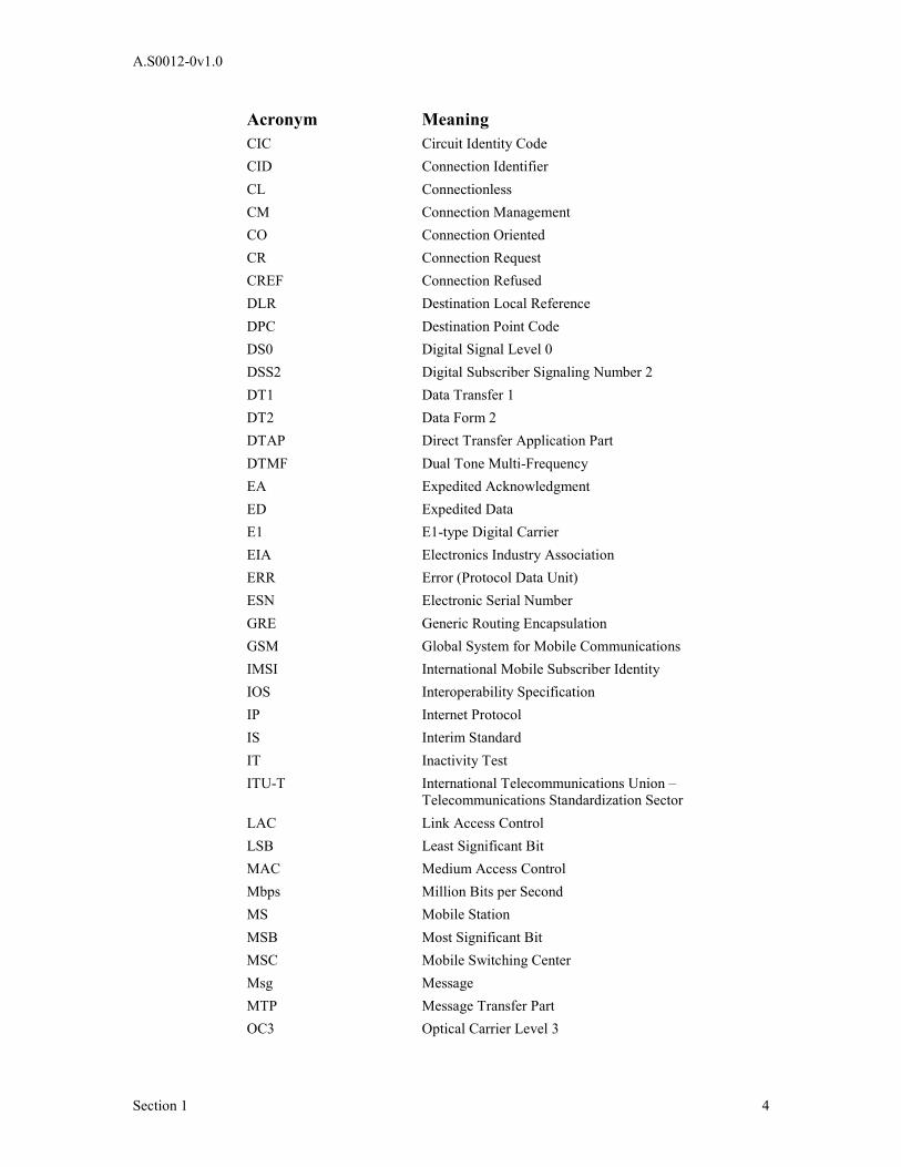
Acronym Meaning CIC Circuit Identity Code CID Connection Identifier CL Connectionless CM Connection Management CO Connection Oriented CR Connection Request CREF Connection Refused DLR Destination Local Reference DPC Destination Point Code DS0 Digital Signal Level 0 DSS2 Digital Subscriber Signaling Number 2 DT1 Data Transfer 1 DT2 Data Form 2 DTAP Direct Transfer Application Part DTMF Dual Tone Multi-Frequency EA Expedited Acknowledgment ED Expedited Data E1 E1-type Digital Carrier EIA Electronics Industry Association ERR Error (Protocol Data Unit) ESN Electronic Serial Number GRE Generic Routing Encapsulation GSM Global System for Mobile Communications IMSI International Mobile Subscriber Identity IOS Interoperability Specification IP Internet Protocol IS Interim Standard IT Inactivity Test ITU-T International Telecommunications Union –
Telecommunications Standardization Sector LAC Link Access Control LSB Least Significant Bit MAC Medium Access Control Mbps Million Bits per Second MS Mobile Station MSB Most Significant Bit MSC Mobile Switching Center Msg Message MTP Message Transfer Part OC3 Optical Carrier Level 3
Page 11
A.S0012-0v1.0
Section 1 5
Acronym Meaning PACA Priority Access and Channel Assignment PCF Packet Control Function PDSN Packet Data Serving Node PLMN Public Land Mobile Network PPP Point to Point Protocol PVC Permanent Virtual Circuit QoS Quality of Service RFC Remote Feature Control, also Request For Comment RLC Release Complete (SCCP) RLSD Release (SCCP) RSC Reset Confirm RSR Reset Request SCCP Signaling Connection Control Part SDU Selection/Distribution Unit, also Service Data Unit (ATM) SID Session Identifier SLR Source Local Reference SLS Signaling Link Selection SLTM Signaling Link Test Message SOG Subsystem Out-of-service Grant SOR Subsystem Out-of-service SP Signaling Point SS7 Signaling System Number 7 SSADT Service Specific Assured Data Transfer SSN Subsystem Number SSSAR Service Specific Segmentation and Reassembly SSTED Service Specific Transmission Error Detection STP Signal Transfer Point T1 T1-type Digital Carrier T3 T3-type Digital Carrier TCP Transmission Control Protocol TFA Transfer-Allowed Signal TFP Transfer-Prohibited Signal TFR Transfer-Restricted Signal TIA Telecommunications Industry Association UDP User Datagram Protocol UDT Unit Data (SCCP) UDTS Unit Data Service (SCCP) UNI User Network Interface VC Virtual Circuit Ver Version
Page 12
A.S0012-0v1.0
Section 1 6
1.3.2 Definitions 1
TBD 2
3
Page 13
A.S0012-0v1.0
Section 2 7
2.0 Network and Transport Protocols 1
2.1 Signaling Connection Transport Protocol Options 2
Signaling over the A1, A3 and A7 interfaces requires a reliable transport protocol and 3
appropriate addressing and routing mechanisms to deliver messages from source to 4
destination. The IOS application is independent of the underlying transport, which is left 5
to the discretion of operators and manufacturers. The signaling protocol stack options 6
available to operators and manufacturers for the A1, A3 and A7 interfaces include: 7
Physical Layer
MTP 1
MTP 2
MTP3
SCCP
IOS Application
8
Figure 2.1-1 A1 Signaling Protocol Stack 9
Physical Layer
ATM
AAL5
IP
TCP
IOS Application
10
Figure 2.1-2 Protocol Stack for A3 and A7 Signaling Interfaces 11
Page 14
A.S0012-0v1.0
Section 2 8
Physical Layer
Link Layer
IP
TCP/UDP
A9 Signaling
1
Figure 2.1-3 A9 Signaling Protocol Stack 2
Physical Layer
Link Layer
IP
UDP
A11 Signaling
3
Figure 2.1-4 A11 Signaling Protocol Stack 4
2.2 User Traffic Connection Transport Protocol Options 5
The protocol stack options for transport of user traffic that are available to operators and 6
manufacturers include: 7
DS0
56/64 kbps PCM
DS0
64 kbps UDI
or
8
Figure 2.2-1 A2 User Traffic Protocol Stacks 9
Page 15
A.S0012-0v1.0
Section 2 9
DS0
ISLP
Data Octet Stream
1
Figure 2.2-2 A5 User Traffic Protocol Stacks 2
Physical Layer
ATM
AAL2
SSSAR
User Traffic
3
Figure 2.2-3 Protocol Stack for A3 User Traffic Interface 4
Physical Layer
Link Layer
IP
GRE
5
Figure 2.2-4 A8 User Traffic Protocol Stack 6
Physical Layer
Link Layer
IP
GRE
7
Figure 2.2-5 A10 User Traffic Protocol Stack 8
9
Page 17
A.S0012-0v1.0
Section 3 11
3.0 Physical Layer Specification (Layer 1) 1
The A1, A2, A3, A5 and A7 interfaces are based on the use of: 2
♦ T1 digital transmission system interfaces. Each 1.544 Mbps interface provides 3
24*56 kbps or 24*64 kbps channels which can be used for traffic or signaling as 4
the operator requires. Common physical interface standards are found in [32] 5
and related references. For a list of references, refer to section 1.2. 6
♦ E1 digital transmission interfaces consisting of 30*64 kbps user channels can 7
also be used for traffic or signaling as the operator requires, and as applicable to 8
the network. 9
As a BS/MSC agreed option, dedicated DS0 signaling link[s] may be used instead of 10
the T1/E1 interface. 11
♦ T3 digital transmission interfaces supporting transmission rates of 43.232 Mbps. 12
♦ OC3 digital transmission interfaces supporting transmission rates of 155.52 13
Mbps. 14
The A8, A9, A10 and A11 interfaces are based on the use of the Internet Protocol (IP). IP 15
can operate across various physical layer media. The specific layer 1 media and layer 2 16
link protocols to be used for these interfaces are not specified in this standard. 17
Page 19
A.S0012-0v1.0
Section 4 13
4.0 Use of ANSI SS7 Transport (Layer 2) 1
This standard specifies multiple protocols for the transport of signaling and user 2
information. See section 2. 3
When SS7 is used to provide signaling transport, the underlying transport mechanism 4
defined to carry signaling information between the BS and the MSC is the Message 5
Transfer Part (MTP), and the Signaling Connection Control Part (SCCP) of Signaling 6
System No. 7 (SS7). 7
The MTP and SCCP are used to transport the application layer signaling protocol which 8
is defined as the BS Application Part (BSAP). 9
Information for this section was excerpted from [33] and [34]. 10
This section is divided into two parts. Section 4.2 deals with the Message Transfer Part 11
(MTP). Section 4.3 deals with the Signaling Connection Control Part (SCCP) and its use. 12
The MTP provides a mechanism giving reliable transfer of signaling messages. Section 13
4.2 deals with the subset of the MTP that can be used between a Base Station (BS) and a 14
Mobile Switching Center (MSC), which is compatible with a full MTP. 15
The SCCP is used to provide a referencing mechanism to identify a particular transaction 16
relating to, for instance, a particular call. Section 4.3 identifies the SCCP subset that shall 17
be used between a BS and an MSC. The SCCP can also be used to enhance the message 18
routing for operations and maintenance information. 19
4.1 Field of Application 20
This section is applicable to the signaling between BSs and MSCs in Public Land Mobile 21
Networks (PLMNs). It provides a minimum set of MTP requirements that may be 22
implemented at a BS or MSC, while maintaining compatibility with the implementation 23
of a full specification of the MTP. 24
This section defines the interfaces at the 56 or 64 kbps boundary to the BS or MSC and 25
applies primarily to digital access arrangements. The use of analog arrangements is not 26
supported. 27
The reliability of signaling links is an administrative concern. It is recommended that in 28
the case where more than one multiplex system is required and reliability reasons dictate 29
the use of a multiple link sets, then each signaling link should be assigned in a different 30
multiplex system. 31
Only the associated mode of signaling is applicable to the BS. 32
The ANSI recommendations concerning MTP shall be taken as being requirements 33
unless covered by a statement in this section. 34
Page 20
A.S0012-0v1.0
Section 4 14
4.2 Message Transfer Part 1
4.2.1 General 2
The MTP functions as specified in [33] are applicable. However, the following 3
exceptions and modifications to those recommendations may be applied for the MSC to 4
BS signaling. See section 4.2.2 through section 4.2.4. 5
4.2.2 Level 1 (T1.111.2) 6
T1.111.2 Figure 2 7
These figures are for information only. For the MSC-BS Interface, interface point C is 8
appropriate. 9
T1.111.2 Section 1.4 Analog Signaling Link 10
The use of analog signaling links is not an available option. 11
T1.111.2 Section 2 General 12
A signaling rate of 56/64 kbps is assumed. 13
T1.111.2 Section 3 Error Characteristics and Availability 14
Error characteristics and availability are an operator concern. Excessive errors could lead 15
to inefficient use of the signaling links. 16
T1.111.2 Section 5 Digital Signaling Link 17
The standard arrangement is to derive the signaling link from a T1/E1 digital path. 18
However, dedicated DS0 signaling link[s] may be used as a BS/MSC agreed option. 19
T1.111.2 Section 6 Analog Signaling Data Link 20
Only digital signaling data links are supported. 21
4.2.3 Level 2 (T1.111.3) 22
T1.111.3 Section 1.4 Signal Unit Error Correction 23
Only the basic error correction protocol is required. 24
T1.111.3 Section 7 Signaling Link Initial Alignment Procedure 25
In the initial alignment procedure specified in Recommendation T1.111.3 [33], only the 26
emergency proving is applicable for the BS. Thus, in states 02 and 03 of the initial 27
alignment procedure status indication "N" is not sent from the BS. The BS should be 28
capable of recognizing status indication "N" if received in order for the alignment 29
procedure to complete. 30
Page 21
A.S0012-0v1.0
Section 4 15
4.2.4 Level 3 (T1.111.4) 1
T1.111.4 Section 1.1.2 End Point of a Signaling Link 2
The BS is only implemented as the end point of a signaling link. There will be no 3
Signaling Transfer Point (STP) network management features in the BS. 4
T1.111.4 Section 2 5
Since STP working is not required for the discrimination and routing functions of the 6
MTP used for MSC-BS can be significantly simplified. 7
Since the implementation of this interface is intended only for point to point application 8
the routing function within the MTP will be preset to select the point code appropriate to 9
the parent MSC. 10
T1.111.4 Section 2.2 Routing Label 11
Load sharing will be performed on the BS with more than one signaling link by means of 12
the Signaling Link Selection field (SLS). 13
T1.111.4 Section 2.3 Message Routing Function 14
Load sharing between link sets is not required since there will only be one link set 15
between the BS and MSC. 16
T1.111.4 Section 2.3.5 Handling of Messages under Signaling Link Congestion 17
The procedures for handling message congestion priority levels as defined for U. S. 18
Signaling Networks in T1.111.4 Section 2.3.5.2 [33] shall be followed. The message 19
priorities given in Appendix B of T1.111.5 [33] for SCCP and MTP messages shall be 20
used. The remaining message priorities for BSMAP and DTAP messages are provided in 21
[14]. 22
T1.111.4 Section 2.4 Message Discrimination 23
At the BS only messages with a correct Destination Point Code (DPC) will be accepted. 24
Other messages will be discarded. It is recommended that discarding a message because 25
of an incorrectly set point code should cause an incident report to be generated. 26
At an MSC (which has the capability of acting as an STP) an administration may decide 27
that each message received from a BS signaling link is passed through a “screening” 28
function that checks that the DPC of the message is the same as the Signaling Point (SP) 29
code of the exchange. If that is the case, the message is sent to the normal MTP message 30
handling functions. Otherwise, the message is discarded and an incident report is made. 31
T1.111.4 Section 3 Signaling Network Management 32
Since the MSC-BS Interface utilizes point to point signaling between the BS and the 33
MSC, the Signaling Route Management procedures, including the status of signaling 34
routes, signaling route restricted, signaling route unavailability and availability, are not 35
required. 36
Page 22
A.S0012-0v1.0
Section 4 16
T1.111.4 Section 3.8 Signaling Network Congestion 1
The procedures defined for U. S. Networks shall be followed for handling congestion on 2
signaling links. 3
T1.111.4 Section 4 Signaling Traffic Management 4
Since the MSC-BS Interface utilizes point to point signaling, the Traffic Management 5
procedures supporting signaling routes, including signaling route restricted, signaling 6
route unavailability and availability, are not required. 7
T1.111.4 Section 4.2 8
The normal routing situation will be that there are one or more signaling links available 9
between the BS and MSC, and these will constitute a link set. They will be run in a load 10
sharing mode and changeover and change back procedures will be supported between 11
these signaling links. 12
T1.111.4 Section 4.3.3 13
There will be no alternative link set. 14
T1.111.4 Section 5 Changeover 15
Changeover between link sets is not applicable. 16
T1.111.4 Section 6 Change back 17
Change back between link sets is not applicable. 18
T1.111.4 Section 7 Forced Rerouting 19
Forced rerouting is not applicable since there is only one signaling route existing between 20
the BS and the MSC. 21
T1.111.4 Section 8 Controlled Rerouting 22
Controlled rerouting is not applicable since there is only one signaling route existing 23
between the BS and the MSC. 24
T1.111.4 Section 9 MTP Restart 25
The MTP Restart procedure is not required. 26
T1.111.4 Section 11 Signaling Traffic Flow Control 27
The Signaling Route Management procedures supporting signaling traffic flow control 28
including signaling route unavailability and signaling route set congestion are not 29
applicable for the MSC-BS Interface. 30
T1.111.4 Section 12 Signaling Link Management 31
Only basic link management procedures are applicable. 32
Page 23
A.S0012-0v1.0
Section 4 17
T1.111.4 Section 13 Signaling Link Management 1
Signaling Route Management procedure is not applicable for the MSC-BS Interface since 2
it is a point to point connection. No action is required upon reception of a TFP, TFR, 3
TFA, Signaling Route Set Test, Signaling Route Set Congestion Test, or Transfer Control 4
message. 5
T1.111.4 Section 14.2.1 6
Since all messages are passed using the SCCP, the service indicator will be: D=0, C=0, 7
B=1, A=1. 8
T1.111.4 Section 14.2.2 9
The sub service field will always be set to indicate a national network as follows: D=1, 10
C=0. 11
T1.111.4 Section 15 12
The formats and codes listed are only relevant to the messages that are required. 13
4.2.5 Testing and Maintenance (T1.111.7) 14
T1.111.7 Section 2.1 Signaling Data Link Test 15
The Signaling Data Link Test procedure is not required for the MSC-BS Interface. 16
T1.111.7 Section 2.2 17
The generation of a Signaling Link Test Message (SLTM) is not applicable at the BS, 18
however the BS shall be capable of responding with an acknowledgment message to a 19
SLTM. 20
4.2.6 Interface Functions 21
The method of interfacing to the higher layers will be by the primitives defined in 22
T1.111.1 [33]. 23
The primitives defined are: 24
♦ MTP Pause indication 25
♦ MTP Resume indication 26
♦ MTP Status indication 27
♦ MTP Transfer request 28
♦ MTP Transfer indication 29
4.2.7 Overload Control (Message Throughput Congestion) 30
MTP overload control is not required. 31
Page 24
A.S0012-0v1.0
Section 4 18
4.3 SCCP Transport Layer Specification (SCCP Functions) 1
4.3.1 Overview 2
The purpose of this section is to identify the subset of the SCCP functions that are 3
necessary to achieve the management of the MS transactions in the MSC-BS interface, 4
and to provide addressing facilities. If this subset of SCCP functions is implemented, 5
compatibility with a full ANSI SCCP shall be maintained. Only the needs of the BSAP 6
are taken into account in this section. 7
The following simplifications are applicable to the signaling between BS and MSC in 8
PLMNs: 9
♦ In order to limit the complexity of the procedures, a BS exchanges signaling 10
messages only with its MSC, where a protocol conversion may be needed in 11
some cases. Therefore, no SCCP translation function is required in the MSC 12
between the national and the local SCCP and MTP within the MSC area. 13
♦ Several functions of the SCCP are not used on the MSC-BS interface: error 14
detection, receipt confirmation, and flow control. 15
♦ The segmenting/reassembling function shall be used if the total message length 16
exceeds the maximum allowed message length that can be carried by the MTP. 17
♦ T1.112.1 through T1.112.4 are considered as the basis for elaboration of this 18
document. 19
4.3.2 Primitives (T1.112.1) 20
T1.112.1 Table 1 21
Two primitives of the table are not used: 22
N-INFORM DATA 23
N-RESET 24
T1.112.1 Table 2 25
The following parameters of the N-CONNECT primitive are not used: 26
Responding address 27
Receipt confirmation selection 28
Expedited data selection 29
T1.112.1 Table 3 30
The following parameter of the N-DATA primitive is not used: 31
Confirmation request 32
T1.112.1 Table 6 33
The following parameter of the N-DISCONNECT primitive is not used: 34
Responding address 35
Page 25
A.S0012-0v1.0
Section 4 19
T1.112.1 Section 2.1.2 1
Permanent signaling connections are not applicable. 2
T1.112.1 Table 8 3
The primitive N-NOTICE is not used. 4
T1.112.1 Table 8A 5
The following parameter of the N-UNITDATA is not used: 6
Return option 7
T1.112.1 Section 4.1.2 8
Functions for permanent signaling connections are not applicable. 9
4.3.3 SCCP Messages (T1.112.2) 10
T1.112.2 Section 2.4 11
The Data Acknowledgment (AK) message is not used. 12
T1.112.2 Section 2.6 13
The Data Form 2 (DT2) message is not used. 14
T1.112.2 Section 2.7 15
The Expedited Data (ED) message is not used. 16
T1.112.2 Section 2.8 17
The Expedited Data Acknowledgment (EA) message is not used. 18
T1.112.2 Section 2.10 19
The Protocol Data Unit Error (ERR) message is not used; the inconsistent messages of 20
the SCCP protocol are discarded. 21
T1.112.2 Section 2.13 22
The Reset Confirm (RSC) message is not used. 23
T1.112.2 Section 2.14 24
The Reset Request (RSR) message is not used. 25
T1.112.2 Section 3.5 26
The Subsystem-Out-Of-Service-Grant (SOG) message is not used. 27
Page 26
A.S0012-0v1.0
Section 4 20
T1.112.2 Section 3.4 1
The Subsystem-Out-Of-Service (SOR) message is not used. 2
T1.112.2 Section 2.16 3
The Unit Data Service (UDTS) message is not used. 4
T1.112.2 Section 4.2 5
The “credit” parameter field is not used for protocol class 2. However, the parameter 6
shall still be included in the Inactivity Test (IT) message for syntax reasons. 7
T1.112.2 Section 4.6 8
The “error cause” parameter field is not used. 9
T1.112.2 Section 4.10 10
The “receive sequence number” parameter is not used. 11
T1.112.2 Section 4.13 12
The “reset cause” parameter field shall not be used. 13
T1.112.2 Section 4.16 14
The “sequencing/segmenting” parameter field is not used for protocol class 2. However, 15
the parameter shall still be included in the IT message for syntax reasons. 16
Page 27
A.S0012-0v1.0
Section 4 21
4.3.4 SCCP Formats and Codes (T1.112.3) 1
T1.112.3 Section 3.4 2
For point-to-point network structures (i.e., direct connections between the MSC and BS), 3
the called party address may consist of the single element: subsystem number. 4
No global title is used. The signaling point code which is coded in the MTP routing label 5
and the Subsystem Number (SSN) in the called party address allow the routing of the 6
message. 7
T1.112.3 Section 3.4.2.2 8
SSN Values: BSAP = 11111100, (252) 9
Use of alternative values is an administrative concern. 10
BSAP SSN value of 11111101 (253) is the SSN for GSM. In CDG IOS V2.0.0 it was 11
determined that the IOS Open A-Interface should use its own SSN value and this was 12
selected as BSAP = 11111100 (252). 13
T1.112.3 Section 3.4.2.3 14
Global title: refer to T1.112.3 [34] Section 3.4 15
T1.112.3 Section 3.6 16
Protocol Class: the classes 1 and 3 are not used. 17
T1.112.3 Sections 3.8, 3.9, 3.10, 3.13, 3.14 18
Parameters are not used. 19
T1.112.3 Sections 4.8, 4.9, 4.11, 4.12, 4.13, 4.14, 4.15, 4.16 20
Messages are not used. 21
T1.112.3 Section 5.1.1 22
SOR and SOG are not needed. 23
4.3.5 SCCP Procedures (T1.112.4) 24
T1.112.4 Sections 1.1.2.2, 1.1.2.4 25
Protocol classes 1 and 3 are not used. 26
T1.112.4 Section 1.1.3 27
A signaling connection consists of a single connection section. No intermediate nodes are 28
defined in the MSC-BS Interface. 29
The use of multiple connections sections is an administrative concern. 30
Page 28
A.S0012-0v1.0
Section 4 22
T1.112.4 Section 1.2.1 (b) 1
Not applicable for single connections. 2
T1.112.4 Section 2.1 (1.) 3
Global title not used for single connections. 4
T1.112.4 Section 2.2.1 5
Subsystem Number (SSN) is only present in the called party address for single 6
connections. 7
T1.112.4 Section 2.2.2 8
The addressing information may take the following form in the N-CONNECT request 9
primitive: DPC+SSN (for single connections). 10
T1.112.4 Section 2.2.2.2 11
No SCCP translation function is required for single connections. 12
T1.112.4 Section 2.3.1 (3) 13
Not applicable for single connections. 14
T1.112.4 Section 2.3.2 (4) 15
Not applicable for single connections. 16
T1.112.4 Section 3.1.3 17
Not applicable: no protocol class and flow control negotiations. 18
T1.112.4 Section 3.1.5 19
Not applicable. 20
T1.112.4 Section 3.2.2 21
Not applicable. 22
T1.112.4 Section 3.3.4 23
Not applicable. 24
T1.112.4 Section 3.5.1.2 25
Not applicable. 26
T1.112.4 Section 3.5.2 27
Not applicable. 28
Page 29
A.S0012-0v1.0
Section 4 23
T1.112.4 Sections 3.6, 3.7, 3.9, 3.10 1
Not applicable. 2
T1.112.4 Section 4.2 3
Message return is not applicable. 4
T1.112.4 Section 5 5
Only those messages and procedures relating to non-replicated subsystems or nodes are 6
required. At the BS the concerned point will be the parent MSC. The subsystem involved 7
is the BSAP. 8
4.4 Use of the SCCP 9
The MTP and the SCCP are used to support signaling messages between the MSC and 10
the BS. One user function of the SCCP, called Base Station Application Part (BSAP) is 11
defined. The BSAP uses one signaling connection for the transfer of layer 3 messages per 12
active Mobile Station (MS) having one or more active transactions (see section 4.4.3). 13
The BSAP user function is further subdivided into two separate functions called DTAP 14
(Direct Transfer Application Part) and BSMAP (BS Management Application Part). 15
Both connectionless (Class 0) and connection-oriented (Class 2) procedures are used to 16
support the BSMAP. The procedure descriptions in this specification explain whether 17
connection or connectionless services are to be used for each layer 3 procedure. 18
A distribution function located in BSAP, which is reflected in the protocol specification 19
by the layer 3 header , performs the discrimination between the data related to those two 20
subparts. See [14] for more information. 21
This section describes the use of an SCCP connection for an MS transaction. Section 22
4.4.1 identifies the Direct Transfer Application Part. Section 4.4.2 identifies the BS 23
Management Application Part. Section 4.4.3 describes the connection establishment 24
procedures. Section 4.4.4 describes the connection release procedures. [14] describes the 25
distribution between BSMAP and DTAP messages and the data transfer over an SCCP 26
connection. 27
4.4.1 The Direct Transfer Application Part 28
The Direct Transfer Application Part (DTAP) is used to transfer call control and mobility 29
management messages to and from the MS. This layer 3 MSC-BS protocol in support of 30
the MS-MSC call control and mobile management information exchange is referred to 31
within this standard. The messages that transfer these information elements are also 32
defined within this standard. Those messages that are considered DTAP are distinguished 33
from BSMAP messages and are listed in [14] . 34
4.4.2 The BS Management Application Part 35
The BS Management Application Part (BSMAP) supports other procedures between the 36
MSC and the BS related to the MS, or to a cell within the BS, or to the whole BS. The 37
description of the layer 3 protocol for the BSMAP information exchange is contained 38
within this standard. 39
Page 30
A.S0012-0v1.0
Section 4 24
4.4.3 Connection Establishment 1
The initial messages exchanged in call setup are used to establish an SCCP connection 2
for subsequent signaling communications relating to the call. A new connection is 3
established when individual information related to an MS transaction has to be exchanged 4
between a BS and an MSC, and no such transaction exists between the MSC and that BS. 5
Two connection establishment cases have to be distinguished: 6
Case 1. A new transaction (e.g., Location updating, incoming or outgoing call – 7
see [13]) is initiated on the radio path. Following an Access Request 8
made by the MS on the Random Access Channel, the connection 9
establishment is then initiated by the BS. 10
Case 2. The MSC decides to perform an inter-BS Handoff (see [13]). The 11
connection establishment is then initiated by the MSC. 12
4.4.3.1 Establishment Procedure - Case 1 13
In this case, the connection establishment is initiated at the reception by the BS of the 14
first layer 3 message from the MS. Generally, such a message contains the Mobile 15
Identity parameter (ESN, or IMSI). The BS then constructs the first MSC-BS Interface 16
BSMAP message (Complete Layer 3 Information) which includes one of the appropriate 17
DTAP messages (Location Updating Request, CM Service Request, or Paging Response) 18
depending on whether the mobile station is accessing the network for the purpose of 19
registration, call origination, or termination. The Complete Layer 3 Information message 20
is sent to the MSC in the user data field of the SCCP Connection Request message (see 21
[14]). The Complete Layer 3 Information message includes the cell identity and the layer 22
3 message that was received from the mobile. The exact coding of the BSMAP message 23
is specified in [14]. 24
At the reception of the SCCP Connection Request message, the MSC may check, based 25
on the received identity, whether another association already exists for the same MS. If it 26
is the case, the connection establishment is refused. Otherwise, an SCCP Connection 27
Confirm message is sent back to the BS. This message may optionally contain a BSMAP 28
or DTAP message in the user data field. 29
The diagram in Figure 4.4.3-1 shows a successful SCCP connection establishment 30
procedure. 31
Time
a
b
BS MSC
SCCP Connection Conf irm
SCCP Connection Request: Complete Layer 3 Inf o
T3230
Comment
32
Figure 4.4.3-1 SCCP Connection Establishment 33
a. The BS sends an SCCP Connection Request message, including a user data 34
field, to the MSC. The BS then starts timer T32301. 35
1 See [14].
Page 31
A.S0012-0v1.0
Section 4 25
b. Upon receipt an SCCP Connection Confirm message, which shall contain a 1
Layer 3 application message, the BS stops timer T3230 and establishes the 2
connection. 3
The procedures in case of connection establishment refusal are shown in Figure 4.4.3-2. 4
Time
a
b
BS MSC
SCCP Connection Refused
SCCP Connection Request: Complete Layer 3 Info
T3230
Comment
5
Figure 4.4.3-2 SCCP Connection Establishment Refusal 6
a. The BS sends an SCCP Connection Request message, including a user data 7
field, to the MSC. The BS then starts timer T3230. 8
b. The MSC responds with an SCCP Connection Refused message. The BS stops 9
timer T3230. 10
If the user data field of the SCCP Connection Request message contains a Complete 11
Layer 3 Info message with a Location Updating Request application message, the MSC 12
shall respond with a SCCP Connection Refused message with a Location Updating 13
Accept or Location Updating Reject message in the user data field. 14
4.4.3.2 Establishment Procedure - Case 2 15
In this case, the connection establishment is undertaken by the MSC as soon as the MSC 16
decides to perform an inter-BS Handoff. 17
An SCCP Connection Request message is sent to the BS. The user data field of this 18
message shall contain the BSMAP Handoff Request message (see [14]). The layer 3 19
messages shall be transferred in the user data field of the SCCP Connection Request in 20
order to complete the establishment of the relation between the radio channel requested 21
and the SCCP connection as soon as possible. The exact structure of the user data field is 22
explained in [14]. 23
When receiving the SCCP Connection Request message, the BS performs the necessary 24
checking and reserves, in the successful case, a radio channel for the requested handoff. 25
An SCCP Connection Confirm message is also returned to the MSC and shall contain the 26
BSMAP Handoff Request Acknowledge message in the user data field. 27
The diagram in Figure 4.4.3.2-1 shows a successful SCCP connection establishment 28
procedure during handoff. 29
Page 32
A.S0012-0v1.0
Section 4 26
Time
a
b
BS MSC
SCCP Connection Confirm
SCCP Connection Request: Handoff Request
Comment
1
Figure 4.4.3.2-1 SCCP Connection Establishment During Handoff 2
a. The MSC sends an SCCP Connection Request message, including a user data 3
field that contains a Handoff Request application message, to the BS. The 4
MSC starts timer T32312. 5
b. Upon receipt, an SCCP Connection Confirm message, which shall contain the 6
Layer 3 application message Handoff Request Acknowledge, is returned to 7
the MSC. The MSC stops timer T3231. 8
The diagram in Figure 4.4.3.2-2 shows an SCCP connection refusal during handoff. 9
Time
a
b
BS MSC
SCCP Connection Refused
Comment
SCCP Connection Request: Handoff Request
10
Figure 4.4.3.2-2 SCCP Connection Refusal During Handoff 11
a. The MSC sends an SCCP Connection Request message, including a user data 12
field that contains a Handoff Request application message, to the BS. The 13
MSC starts timer T3231. 14
b. Upon receipt, an SCCP Connection Refused message, which contains the 15
Layer 3 application message Handoff Failure, is returned to the MSC. The 16
MSC stops timer T3231. 17
4.4.4 Connection Release 18
This procedure is normally initiated at the MSC side but in the case of abnormal SCCP 19
connection release (see 4.4.5), the BS may initiate connection clearing. 20
The MSC initiates this procedure with respect to the source BS in normal conditions for 21
all calls supported by A1 connections. 22
A connection is released when a given signaling connection is no longer required. This 23
may occur in normal cases: 24
2 See [14].
Page 33
A.S0012-0v1.0
Section 4 27
♦ at the end of a transaction (call, location updating); 1
♦ after completion of a successful external Handoff: the connection with the old 2
BS is released. 3
The MSC/BS sends a SCCP RLSD message. The user data field of this message is 4
optional and may contain a transparent layer 3 message (e.g., DTAP) or be empty. The 5
structure of the user data field, if any, is explained in [14]. 6
When receiving this message, the BS/MSC releases all the radio resources allocated to 7
the relevant MS, if there are still any left, and sends a SCCP RLC back to the MSC/BS. 8
For abnormal cases a connection failure may be detected by the connection supervision 9
service provided by SCCP. If so, the Reset Circuit procedure described in [14] is used. 10
For other abnormal SCCP connection releases, refer to section 4.4.5 “Abnormal SCCP 11
Release”. 12
4.4.5 Abnormal SCCP Release 13
The normal release of SCCP A1 connections is initiated by the MSC. Under abnormal 14
conditions, such an SCCP connection may be released by the BS in order to clear 15
resources. 16
Whenever a SCCP connection is abnormally released, all resources associated with that 17
connection shall be cleared. Abnormal release could result from, for example, resource 18
failure, protocol error, or unexpected receipt of the SCCP RLSD or SCCP RLC 19
command. 20
4.4.5.1 SCCP Release by BS: Loss of SCCP Connection Information 21
Figure 4.4.5.1-1 demonstrates release of an SCCP connection by the BS due to loss of 22
SCCP connection information. Note that when a circuit(s) is associated with the call at 23
the MSC, Reset Circuit/Reset Circuit Ack [14] messages need to be exchanged between 24
the MSC and BS to guarantee release of the circuit by both the MSC and BS. 25
BS MSCtime comment
a
b
SCCP RLSD
c
d
SCCP RLC
Reset Circuit
T12Reset Circuit Ack
Optional
Optional
26
Figure 4.4.5.1-1 BS Generated SCCP Release: BS Has Lost Access 27
to SCCP Connection Information 28
a. An unexpected SCCP RLSD (under abnormal termination) is received by the 29
MSC from the BS. 30
Page 34
A.S0012-0v1.0
Section 4 28
b. The MSC sends an SCCP RLC message to the BS to indicate that the SCCP 1
RLSD message has been received and that the appropriate procedures have 2
been completed. 3
c. If a circuit was involved with the call at the MSC, the MSC sends a Reset 4
Circuit message to inform the BS that had sent the SCCP RLSD to clear its 5
call data and starts timer T123. The Reset Circuit message carries the Circuit 6
Identity Code (CIC) of the trunk whose corrupted connection was released. 7
d. The Reset Circuit Ack message informs the MSC that the Reset Circuit has 8
been received and acted upon. The MSC stops timer T12. 9
4.4.5.2 SCCP Release by MSC: Loss of SCCP Connection Information 10
Figure 4.4.5.2-1 demonstrates release of an SCCP connection by the MSC due to loss of 11
SCCP connection information. Note that when a circuit(s) is associated with the call at 12
the BS, Reset Circuit/Reset Circuit Ack messages [14] need to be exchanged between the 13
MSC and BS to guarantee release of the circuit by both the MSC and BS. 14
BS MSCtime comment
a
b
SCCP RLSD
c
d
SCCP RLC
Reset Circuit
T12Reset Circuit Ack
Optional
Optional
15
Figure 4.4.5.2-1 MSC Generated SCCP Release: MSC Has Lost 16
Access to SCCP Connection Information 17
a. An unexpected SCCP RLSD (under abnormal termination) is received by the 18
BS from the MSC. 19
b. The BS sends an SCCP RLC message to the MSC to indicate that the SCCP 20
RLSD message has been received and that the appropriate procedures have 21
been completed. 22
c. If a circuit was involved with the call at the BS, the BS sends a Reset Circuit 23
message to inform the MSC which had sent the SCCP RLSD to clear its call 24
data and starts timer T12. The Reset Circuit message carries the CIC of the 25
trunk whose corrupted connection was released. 26
d. The Reset Circuit Ack message informs the BS that the Reset Circuit has been 27
received and acted upon. The BS stops timer T12. 28
3 See [14].
Page 35
A.S0012-0v1.0
Section 4 29
4.4.6 SCCP Reference Generation Philosophy 1
Referring to Figure 4.4.6-1 “SLR/DLR Usage,” the SCCP local reference number 2
(source/destination) is a three byte element internally chosen by the MSC or BS to 3
uniquely identify a signaling connection. In the direction MSC to BS, the source local 4
reference is chosen by the MSC and the destination local reference is chosen by the BS. 5
In the direction BS to MSC, the source local reference is chosen by the BS and the 6
destination local reference is chosen by the MSC. In the direction MSC to BS, the MSC 7
always echoes the BS SLR in the DLR field. In the direction BS to MSC, the BS always 8
echoes the MSC SLR in the DLR field. Note that it is the responsibility of the BS and 9
MSC to insure that no two calls have identical SCCP local reference numbers. 10
SLR (MSC), DLR (BS)
SLR (BS), DLR (MSC)
SLR = Source Local ReferenceDLR = Destination Local Reference
MSC BS
11
Figure 4.4.6-1 SLR/DLR Usage 12
MSC generation of SCCP local reference numbers shall conform to ANSI T1.112.4 [34], 13
Section 3.1.2. 14
4.4.7 SCCP Transfer of DTAP and BSMAP Messages 15
The DTAP and BSMAP messages on the A1 interface are contained in the user data field 16
of the exchanged SCCP frames. Table 4.4.7-1 below summarizes the use of the User Data 17
Field in SCCP frames. 18
Table 4.4.7-1 Use of the User Data Field in SCCP Frames 19
SCCP Frame User Data Field (BSMAP/DTAP)
Connection Oriented (CO) Protocol Class 2
SCCP Connection Request (CR) Optional SCCP Connection Confirm (CC) Optional SCCP Connection Refused (CREF) Optional SCCP Released (RLSD) Optional SCCP Release Complete (RLC) Not Applicable SCCP Data Transfer 1 (DT1) Mandatory
Connectionless (CL) Protocol Class 0
SCCP Unit Data (UDT) Mandatory
For connection oriented transactions, a connection is requested, obtained or refused using 20
the following SCCP messages (protocol class class 2): 21
♦ SCCP Connection Request (CR) 22
Page 36
A.S0012-0v1.0
Section 4 30
♦ SCCP Connection Confirm (CC) 1
♦ SCCP Connection Refused (CREF) 2
♦ SCCP Released (RLSD) and SCCP Release Complete (RLC) messages are used 3
to break a connection. 4
The use of the User Data Field in SCCP frames in the various establishment and release 5
cases is described in section 4.4.3 “Connection Establishment” and section 4.4.4 6
“Connection Release.” 7
For connection oriented transactions, once the signaling connection is confirmed between 8
the MSC and the BS, all A1 interface messages are transported in the SCCP Data 9
Transfer 1 (DT1) message until the connection is to be dropped. 10
For Connectionless (protocol class 0) transactions, where there is no SCCP connection, 11
A1 interface messages are transported in the SCCP Unit Data (UDT) message. 12
Table 4.4.7-2 below indicates which SCCP messages shall be used to transport each of 13
the application messages on the A1 interface. 14
Table 4.4.7-2 Use of SCCP for BSMAP and DTAP Messages 15
Application Message
Message Discriminator
SCCP Message
Call Processing Messages Complete Layer 3 Information BSMAP CRa CM Service Request DTAP CRa,g Paging Request BSMAP UDTa Paging Response DTAP CRa,g Connect DTAP DT1 Progress DTAP DT1 Service Release DTAP DT1 Service Release Complete DTAP DT1 Assignment Request BSMAP CCb, DT1 Assignment Complete BSMAP DT1 Assignment Failure BSMAP DT1 Clear Request BSMAP DT1 Clear Command BSMAP DT1 Clear Complete BSMAP DT1 Alert With Information DTAP DT1 BS Service Request BSMAP UDT BS Service Response BSMAP UDT Additional Service Request DTAP DT1 Additional Service Notification BSMAP DT1
16
Page 37
A.S0012-0v1.0
Section 4 31
Table 4.4.7-2 (Cont.) Use of SCCP for BSMAP and DTAP 1
Messages 2
Application Message
Message Discriminator
SCCP Message
Supplementary Services Messages Flash with Information DTAP DT1 Flash with Information Ack DTAP DT1 Feature Notification BSMAP UDTa Feature Notification Ack BSMAP UDTa PACA Command BSMAP CCb, DT1 PACA Command Ack BSMAP DT1 PACA Update BSMAP UDT PACA Update Ack BSMAP UDT Radio Measurements for Position Request
BSMAP DT1
Radio Measurements for Position Response
BSMAP DT1
Mobility Management Messages Authentication Request DTAP/BSMAP DT1/UDTc Authentication Response DTAP/BSMAP DT1/UDTc SSD Update Request DTAP DT1 Base Station Challenge DTAP DT1 Base Station Challenge Response DTAP DT1 Status Request DTAP/BSMAP DT1/UDTc Status Response DTAP/BSMAP DT1/UDTc SSD Update Response DTAP DT1 Location Updating Request DTAP CRa,g Location Updating Accept DTAP CREF Location Updating Reject DTAP CREF Parameter Update Request DTAP DT1 Parameter Update Confirm DTAP DT1 Privacy Mode Command BSMAP DT1 Privacy Mode Complete BSMAP DT1 User Zone Reject DTAP/BSMAP DT1/UDTc User Zone Update DTAP DT1 User Zone Update Request DTAP DT1
3
Page 38
A.S0012-0v1.0
Section 4 32
Table 4.4.7-2 (Cont.) Use of SCCP for BSMAP and DTAP 1
Messages 2
Application Message
Message Discriminator
SCCP Message
Handoff Messages Handoff Required BSMAP DT1 Handoff Request BSMAP CRd Handoff Request Acknowledge BSMAP CCd Handoff Failure BSMAP DT1f, CREFe Handoff Command BSMAP DT1 Handoff Required Reject BSMAP DT1 Handoff Commenced BSMAP DT1 Handoff Complete BSMAP DT1 Handoff Performed BSMAP DT1
Facilities Management Messages Block BSMAP UDT Block Acknowledge BSMAP UDT Unblock BSMAP UDT Unblock Acknowledge BSMAP UDT Reset BSMAP UDT Reset Acknowledge BSMAP UDT Reset Circuit BSMAP UDT Reset Circuit Acknowledge BSMAP UDT Transcoder Control Request BSMAP DT1 Transcoder Control Acknowledge
BSMAP DT1
Application Data Delivery Service (ADDS) Messages ADDS Page BSMAP UDT ADDS Transfer BSMAP UDT ADDS Deliver DTAP DT1 ADDS Page Ack BSMAP UDT ADDS Deliver Ack DTAP DT1 ADDS Transfer Ack BSMAP UDT Error Handling Messages Rejection DTAP/BSMAP DT1/UDTc
Following are the footnotes referred to in Table 4.4.7-2. 3
a. Required, SCCP DT1 is not an option. 4
b. May use in response to CM Service Request or Paging Response. 5
c. Use only when procedure is being done on a paging channel. 6
Page 39
A.S0012-0v1.0
Section 4 33
d. Required only for hard handoffs. 1
e. May be used if responding to an SCCP Connection Request/Handoff Request. 2
f. May be used after an SCCP connection has been established. 3
g. Sent within Complete Layer 3 Information, which is a BSMAP message. 4
5
Page 41
A.S0012-0v1.0
Section 5 35
5.0 Use of ATM (Layer 2) 1
When Asynchronous Transfer Mode (ATM) is used to provide signaling transport, the 2
ATM Adaptation Layer 5(AAL5) protocol is employed. 3
When ATM is used to provide user traffic transport, the AAL2 protocol is used. The 4
procedures defined in [15] determine the allocation and use of the logical channels, i.e., 5
the connection identifiers (CIDs) that AAL2 provides over an ATM virtual circuit. 6
Each BS has two or more ATM virtual circuits that connect it to other BSs (regardless of 7
whether switched or permanent virtual circuits are used). These virtual circuits are 8
comprised of one or more virtual circuits using the AAL5 protocol for signaling, and one 9
or more virtual circuits using AAL2 for the user traffic connections. 10
Use of the AAL5 PVC/SVC as the link layer of IP protocol stack shall follow [44]. 11
Specification of either LLC/SNAP encapsulation or Virtual Channel (VC) multiplexing 12
as per [41] is left to the discretion of operators and manufacturers. 13
5.1 Field of Application 14
Asynchronous Transfer Mode (ATM) is used to transport both signaling and user traffic 15
(voice/data). 16
5.2 ATM Layer 17
The ATM Layer uses a basic 53 octet cell consisting of a 5 octet header and 48 octet 18
payload. This standard uses the ATM Layer as specified in [35] without modification. 19
For this specification only ATM permanent virtual circuits (PVC’s) shall be required for 20
the A3 and A7 interfaces. These virtual circuits shall be configured through 21
administrative procedures and no special signaling interface procedures, e.g., ATM UNI 22
[37], shall be required. 23
5.3 ATM Adaptation Layer 24
To make use of the basic cell transfer capability of the ATM Transport Layer in specific 25
usages, various ATM Adaptation Layers (AALs) have been defined. 26
Within this standard, two AALs are used: 27
♦ AAL5 - for the transfer of signaling, and 28
♦ AAL2 - for the transfer of user traffic (voice/data) on A3 traffic subchannels. 29
Both AAL5 and AAL2 will be used without modification in this standard. The Service 30
Specific Segmentation and Reassembly (SSSAR) sublayer for AAL2, as specified in 31
[36], is used for segmentation and reassembly of AAL2 SDUs. 32
In this version of this standard, the functionality of other sublayers of AAL2 are not 33
supported. Specifically, Service Specific Transmission Error Detection (SSTED) and 34
Service Specific Assured Data Transfer (SSADT) are not included. 35
Page 42
A.S0012-0v1.0
Section 5 36
5.4 Use of ATM AAL5 for Transmission of IP Datagrams 1
Use of the AAL5 PVC/SVC as the link layer of IP protocol stack shall follow [44]. 2
Specification of either LLC/SNAP encapsulation or Virtual Channel (VC) multiplexing 3
as per [41] is left to the discretion of operators and manufacturers. 4
Page 43
A.S0012-0v1.0
Section 6 37
6.0 TCP Transport Protocol Usage 1
The standard TCP protocol, as described in [40], shall be used for establishing, using, and 2
clearing TCP connections. 3
6.1 General Use of TCP 4
TCP connections for signaling may be set up on a per-call basis or signaling messages for 5
multiple calls may be multiplexed on a single TCP connection. 6
The TCP protocol provides a reliable byte stream transfer. Therefore, a means needs to be 7
provided for two application entities to delimit the messages sent between them. The 8
technique for such delimitation is given below. 9
6.1.1 Message Delimiting in TCP 10
TCP provides a reliable byte stream between two application entities. Because the 11
protocol in this standard uses messages to communicate, these messages shall be 12
delimited in the TCP byte stream. Such delimitation shall be done by means of a two byte 13
flag field and a two byte length field inserted at the beginning of each message sent over 14
a TCP connection. The flag field shall contain the hex value “F634”. The purpose of the 15
flag field is to facilitate verification of message boundaries, and fast reestablishment of 16
synchronization if synchronization of message boundaries is lost. See Figure 6.1.1-1. 17
7 6 5 4 3 2 1 0
Flag 1 1 1 1 0 1 1 0 Flag 0 0 1 1 0 1 0 0
Length (MSB) Length (LSB)
First Octet of IOS Application Message
Second Octet of IOS Application Message
Msg Third Octet of IOS Application Message
. . .
Last Octet of IOS Application Message
Flag 1 1 1 1 0 1 1 0 Flag 0 0 1 1 0 1 0 0
Length (MSB) Length (LSB)
-- Continued on next page --
Figure 6.1.1-1 Delimiting Messages in an IOS Application TCP 18
Byte Stream 19
20
Page 44
A.S0012-0v1.0
Section 6 38
1
-- Continued from previous page --
First Octet of IOS Application Message
Second Octet of IOS Application Message
Msg Third Octet of IOS Application Message
. . .
Last Octet of IOS Application Message
Flag 1 1 1 1 0 1 1 0 Flag 0 0 1 1 0 1 0 0
Length (MSB) Length (LSB)
First Octet of IOS Application Message
Second Octet of IOS Application Message
Msg Third Octet of IOS Application Message
. . .
Figure 6.1.1-1 (Cont.) Delimiting Messages in an IOS Application 2
TCP Byte Stream 3
6.1.2 TCP Connection Establishment 4
A new TCP connection is established when a signaling message has to be exchanged over 5
an interface, and no such connection exists over the particular interface. Normal active-6
passive TCP connection establishment procedures are used. 7
6.1.3 TCP Connection Release 8
An existing TCP connection over an interface may be released when there are no more 9
signaling messages to be exchanged over the interface. Normal TCP connection release 10
procedures are used. 11
6.1.4 TCP Port Usage 12
The following TCP port values are reserved for signaling across A interfaces: 13
♦ A7: (BS-to-BS) 5602 — This is the registered TCP port at a BS used for 14
signaling interconnection to another BS. 15
♦ A9: (BS-to-PCF) 5603 — This is the registered TCP/UDP port at a BS used for 16
signaling interconnection to a PCF. 17
6.2 Use of TCP for the A3 and A7 Interfaces 18
The standard "Transmission Control Protocol (TCP)", as described in [40] and shown in 19
section 6.1 shall be used on the A3 (signaling subchannel) and A7 interfaces. 20
All response messages associated with the handoff procedures shall be sent back to the 21
same TCP connection where the first A3 or A7 message initiating the procedure is 22
Page 45
A.S0012-0v1.0
Section 6 39
received. For example, A3-Connect Ack message is sent back to the same TCP 1
connection from which A3-Connect message is received. 2
Any A3 or A7 signaling link disconnection during a handoff procedure may result in a 3
failure of the handoff procedure. Optionally, a connection recovery may be performed for 4
continuation of the handoff procedures. If a connection recovery is performed, the same 5
active-passive TCP establishment procedure shall be used. 6
6.3 Use of TCP for the A9 Interface 7
When TCP is used for transferring the A9 interface messages, the standard "Transmission 8
Control Protocol (TCP)", as described in [40] and shown in section 6.1, shall be used. 9
10
Page 47
A.S0012-0v1.0
Section 7 41
7.0 IP Network Protocol Usage 1
The standard IP protocol, as defined in [39], shall be used for routing Internet Protocol 2
packets. When IP is used as the network layer for the A10 bearer, standard IP QoS 3
mechanisms may be employed. 4
5
Page 49
A.S0012-0v1.0
Section 8 43
8.0 UDP Transport Protocol Usage 1
8.1 UDP Transport Protocol Usage for the A11 Interface 2
The use of UDP over the A11 interface conforms to the use of UDP for Mobile IP, as 3
specified in [43]. 4
8.2 UDP Transport Protocol Usage for the A9 Interface 5
When UDP is used for transferring the A9 interface messages, the standard "User 6
Datagram Protocol (UDP)", as described in [38], shall be used. 7
The following UDP port value is reserved for signaling across A9 interface: 8
A9: (BS-to-PCF) 5603 — This is the registered UDP port at a BS used for signaling 9
interconnection to a PCF. 10
The initiator of an A9_Link (BS) would pick an available source UDP port, and send an 11
A9-Setup-A8 message to the destination ( PCF) at port 5603. The PCF will respond with 12
an A9-Connect-A8 message to the initiator's (BS) UDP port that initiated the A9-Setup-13
A8 message. 14
The UDP protocol provides a transfer mechanism between the BS and the PCF with a 15
minimum of overhead. 16
17
Page 51
A.S0012-0v1.0
Section 9 45
9.0 Mobile IP Protocol Usage 1
Mobile IP based messages are used for A11 interface call control signaling and for 2
passing accounting related and other information from the PCF to the PDSN. The A11 3
interface messages use Mobile IP well-known port (699). Each control message is 4
transported within a UDP datagram. The initiator of the A10 connection (PCF) picks an 5
available source UDP port, and sends a connection request message to the selected PDSN 6
at UDP port 699. The recipient (PDSN) sends a reply message to the initiator’s (PCF) 7
UDP port that initiated the connection request. 8
Page 53
A.S0012-0v1.0
Section 10 47
10.0 GRE Protocol Usage 1
The upper layer for the A8 and A10 interfaces is the Generic Routing Encapsulation 2
protocol (GRE) as defined in [42]. 3
GRE encapsulates user traffic as shown below. 4
GRE Header User Traffic
5
Figure 10-1 GRE Encapsulated User Traffic 6
Figure* 10-2 shows the structure of the GRE header. 7
Figure 10-2 GRE Header 8
The flags and other fields in the GRE header are encoded as follows: 9
C (Checksum Present) ‘0’ 10
R (Routing Present) ‘0’ 11
K (Key Present) ‘1’ 12
S (Sequence Number Present) ‘0/1’ 13
s (Strict Source Route Present) ‘0’ 14
Recur (Recursion Control) ‘0s’ 15
Flags ‘0s’ 16
Ver (Version Number) ‘0s’ 17
Protocol Type Hex ‘88 0B’ for PPP 18
(Note: currently this value is not supported 19
by [25], but is reserved for pure PPP.) 20
Hex ’88 81’ for Unstructured Byte Stream 21
The PDSN shall set the Key field in the GRE header to the PCF Session Identifier (PCF 22
SID) for the call, whereas the PCF shall set the Key field in the GRE header to the PDSN 23
SID. If the link layer/network layer protocol requires that the packets be delivered in 24
sequence, the sequence number field is used. The Sequence Numbers are per packet 25
sequence numbers. Both the BS/PCF and the PDSN set the Sequence Number to zero at 26
C R K S s Recur Flags Ver Protocol Type
Key
Sequence Number (optional)
00 1 2 3 4 5 6 7 8 9
10 1 2 3 4 5 6 7 8 9
20 1 2 3 4 5 6 7 9
30 1 Bit Num.
Octet: 1-4
Octet: 5-8
Octet: 9-12
2
Page 54
A.S0012-0v1.0
Section 10 48
packet session startup. Each packet sent for a given session is assigned the next 1
consecutive sequence number. Roll-overs of the sequence numbers are handled 2
appropriately. For protocols such as PPP and Async PPP, that require in-sequence receipt 3
of packets, if the packets arriving at the BS/PCF or the PDSN lose their sequencing 4
across the A10/A11 interface, the receiving entity may attempt to resequence the packets 5
before delivering to the PPP layer. 6