24
Schematic Layout Development Northeast Hangar Area Manassas Regional Airport Manassas, Virginia November 2015

Schematic Layout DevelopmentNortheast Hangar Area
Manassas Regional AirportManassas, Virginia
November 2015

Schematic Layout Report: Northeast Hangar Area
November 2015 Page 1 of 22
Introduction
In response to the continuing development demand at Manassas Regional Airport, the following report summarizes the methodology and findings associated with the development of schematic layouts for the northeast hangar area.
The intent of this effort was to develop a concept that demonstrates the overall potential for the northeast hangar complex. The resulting layouts presented herein are not intended to establish final layouts or limits, only to document that development is possible, and to what overall magnitude. Once demand generates a need to expand into this area, a more detailed preliminary engineering effort should be completed. Additional data will also need to be gathered and taken into consideration, including but not limited to:
•Formalenvironmentalclearance(EnvironementalAssessment)
•FieldcoordinationwithvariousagenciesonRPA/Wetlandlimits (Informationusedinthisreportisbasedonaerialinformation only.Formalinvestigationswerenotundertaken.)
•Floodplainimpacts/assessments
•Trafficimpactonlocalroadsincludingqueueingforrailroad crossings
•Utilitycapacity
• Developmentcriteria/inter facewithpor tionsof site located withinPrinceWilliamCounty,includingCoastalZonecoordination
•Stormwaterqualityandquantitymanagement

Schematic Layout Report: Northeast Hangar Area
November 2015 Page 2 of 22
SiteInformation/Background
Manassas Regional Airport is a public use airport, owned and operated by the CityofManassas,Virginia. Just thirtymiles southofournation’s capital, theAirport’sfacilitiesandlocationmakeitakeyregionalasset(seeFigure 1).TheFederal Aviation Administration has recognized Manassas’s importance bydesignating it as one of the 84 national General Aviation airports, providing communities access to national and international markets. The airport is served byanAirTrafficControlTower,andishometoseveralbusinesses,basingseverallarge turbine corporate aircraft.
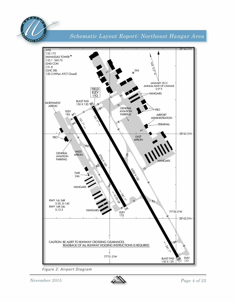
As presented in Figure 2,Runway16L-34R(6,200’x100’)istheairport’sprimaryrunway and is supported by parallel Runway 16R-34L (3,702’ x 100). Runway16L’s Instrument LandingSystem (ILS)approachallows theairport to functionduringmost visibility conditions by providing 1/2mile visibility and 200 footceiling minimums. The parallel runway system is served by several taxiways which lead from hangar, FBO, and apron areas located to either side of theparallel runway complex. The airport terminal building is the center of a variety ofservicesforarrivinganddepartingtravelers, those inneedofU.S.Customsassistance, and pilots.

Schematic Layout Report: Northeast Hangar Area
November 2015 Page 3 of 22
IADAirport
JYOAirport
DCAAirport
ManassasRegional Airport
(HEF)
GAIAirport
10 M
i l es 20
Miles
N
GRAPHIC SCALE: 1" = 5 Mile
5 0 5
Figure 1: Vicinity Map
Schematic Layout Report: Northeast Hangar Area
November 2015 Page 4 of 22
NE
-3, 15 OC
T 2015 to 12 NO
V 2015
NE
-3, 1
5 O
CT
2015
to 1
2 N
OV
201
5
Figure 2: Airport Diagram

Schematic Layout Report: Northeast Hangar Area
November 2015 Page 5 of 22
Northeast Hangar Area
ShownonFigure 3, the northeast hangar complex is home to some of the larger aircraft and business based users. The northeast area has been expanded to a point where any future expansion is very limited or a change in development patterns would be necessary. The purpose of this paper is to present the general constraints on expansion within the existing limited “footprint” and to explore expansion options to the east of the complex, acrossWakemanDrive.
Figure 3: Northeast Hangar Complex
Schematic Layout Report: Northeast Hangar Area
November 2015 Page 6 of 22
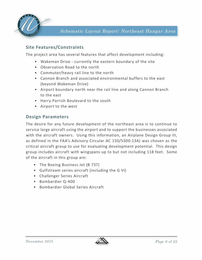
Site Features/ConstraintsThe project area has several features that affect development including:
• WakemanDrive-currentlytheeasternboundaryofthesite• Observation Road to the north• Commuter/heavyraillinetothenorth•CannonBranchandassociatedenvironmentalbufferstotheeast (beyondWakemanDrive)•AirportboundarynorthneartheraillineandalongCannonBranch to the east•HarryParrishBoulevardtothesouth•Airporttothewest
Design ParametersThe desire for any future development of the northeast area is to continue to service large aircraft using the airport and to support the businesses associated withtheaircraftowners. Usingthisinformation,anAirplaneDesignGroupIII,asdefined intheFAA’sAdvisoryCircularAC150/5300-13A)waschosenasthecritical aircraft group to use for evaluating development potential. This design groupincludesaircraftwithwingspansuptobutnotincluding118feet.Someof the aircraft in this group are:
•TheBoeingBusinessJet(B737)•Gulfstreamseriesaircraft(includingtheGVI)•ChallengerSeriesAircraft•BombardierQ-400•BombardierGlobalSeriesAircraft
Schematic Layout Report: Northeast Hangar Area
November 2015 Page 7 of 22
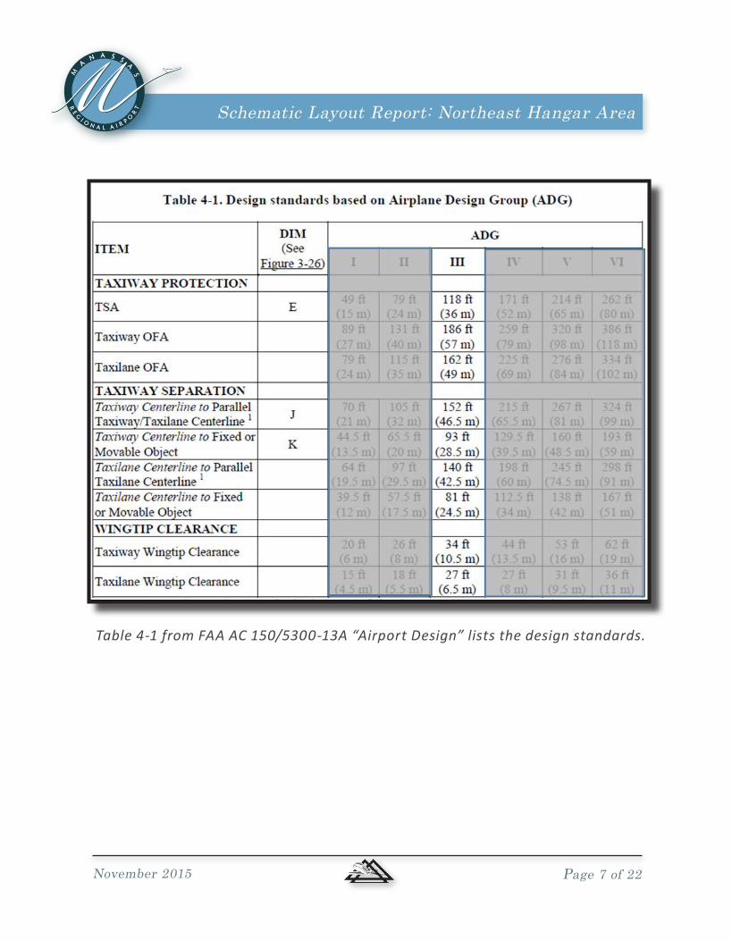
Table 4-1 from FAA AC 150/5300-13A “Airport Design” lists the design standards.

Schematic Layout Report: Northeast Hangar Area
November 2015 Page 8 of 22
Option 1
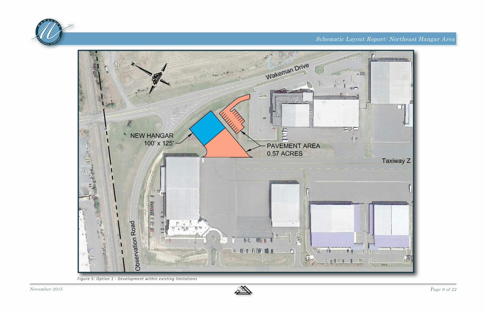
While indicated as not desirable by airport staff and inconsistent with theAirportLayoutPlan(SeeFigure 4),anoptionwasdevelopedusingtheexistingphysical limits, specifically Wakeman Drive. As presented on Figure 5, the development potential within the immediate footprint of the site is limited.
•Ahangarsmallerthanthedesiredaircraftsize•Problematicsiteaccessthruanexistingleasearea•LikelynodirectaccesstoObservationRoadorWakemanDrive•Precludesfuturegrowthtotheeastwithoutremovaloffacility•UnlikelytomeetCitydesignstandardrequirementforsetbacks,etc.•InconsistentwithcurrentAirportLayoutPlan
DevelopmentOptions
Figure 4: Plan for Northeast quadrant from Airport Layout Plan
Whileother concepts arepossible, theoption shownprovides thenecessaryperspective to identify issues including:
Schematic Layout Report: Northeast Hangar Area
November 2015 Page 9 of 22
Figure 5: Option 1 - Development within existing limitations

Schematic Layout Report: Northeast Hangar Area
November 2015 Page 10 of 22
Option 2
Option2wasdevelopedtoevaluatethepotentialofexpandingtotheeast.As shown on Figure 6, for this Option, the road was relocated to the eastern most boundary, established by approximating a 100 foot environmentalbufferalongCannonBranch(whichisalsoclosetotheairportpropertyline).
It ’s important to note that this environmental buffer is approximate;formal surveys and an environmental assessment would be required priorto any construction. These surveys and assessment would likely revise the boundary.Howeverforthepurpose/goalofthiseffort,theboundarylocationisadequate.
With the eastern boundary defined, the next step for Option 2 was todetermine where and how aircraft could move from the existing airfield pavementstotheareaopenedfordevelopment.Byworkingnorthtosouth,five general areas of development were defined as presented below.
Figure 6: Option 2 - Development with adjustments to Wakeman Drive and other features

Schematic Layout Report: Northeast Hangar Area
November 2015 Page 11 of 22
Area 1, the northern most site, shown in Figure 7, is providing the most promise for large hangars as the space available is relatively deep compared to the rest of the overall site.
Highlights of Option 2 - Area 1 include:
The ability to phase the relocation of Wakeman Drive. Whilenot ideal for traffic flow, the phased relocation shown allows for incremental financial commitment.
ApronspaceandtaxilanesdesignedforGroupIIIaircraft(wingspansupto118feet,taxilaneobjectfreewidthis162’).
Potentialforlargehangars.Thoseshown are for visual references only. Actual hangar size(s) willdepend on need of future tenant.
To accommodate new apron, existing autoparking needs to be relocated. A parking lot east of existingWakemanDrivehasbeenshown to replace those spaces lost. It is important to note that the lot size is based on maximizing the general space available and not based on any space demand.
Phase I relocation of WakemanDrive.
•
•
•
•
Option 2 - Area 1It islikelythatanyrelocationofWakemanDrivewillrequireasubstantialcommitment by a tenant to justify the local costs associated with the road relocation. Items that would have to be addressed include environmental impactsandacrossingofasmallstream/ditch.
Figure 7: Option 2 - Area 1
•
Schematic Layout Report: Northeast Hangar Area
November 2015 Page 12 of 22
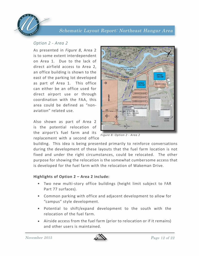
Option 2 - Area 2As presented in Figure 8, Area 2is to some extent interdependent on Area 1. Due to the lack ofdirect airfield access to Area 2,an office building is shown to the east of the parking lot developed as part of Area 1. This office can either be an office used for direct airport use or through coordination with the FAA, thisarea could be defined as “non-aviation” related use.
Also shown as part of Area 2is the potential relocation of the airport’s fuel farm and itsreplacement with a second office building. This idea is being presented primarily to reinforce conversations during the development of these layouts that the fuel farm location is not fixed and under the right circumstances, could be relocated. The other purpose for showing the relocation is the somewhat cumbersome access that isdevelopedforthefuelfarmwiththerelocationofWakemanDrive.
Highlights of Option 2 – Area 2 include:
•
•
•
•
Two new multi-story office buildings (height limit subject to FARPart77surfaces).
Commonparkingwithofficeandadjacentdevelopmenttoallowfor“campus” style development.
Potential to shift/expand development to the south with therelocation of the fuel farm.
Airsideaccessfromthefuelfarm(priortorelocationorifitremains)and other users is maintained.
Figure 8: Option 2 - Area 2
Schematic Layout Report: Northeast Hangar Area
November 2015 Page 13 of 22
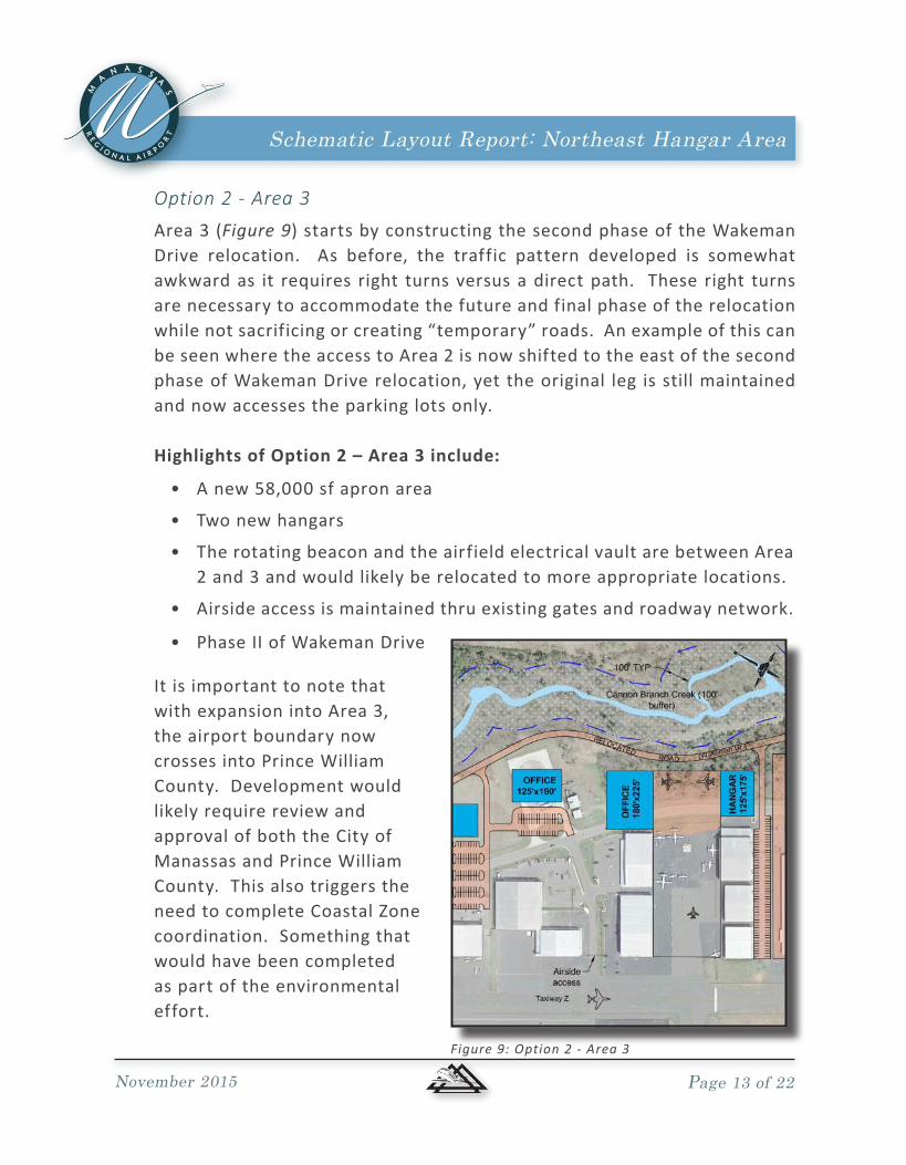
Option 2 - Area 3Area3(Figure 9)startsbyconstructingthesecondphaseoftheWakemanDrive relocation. As before, the traffic pattern developed is somewhatawkwardas it requires right turnsversusadirectpath. These right turnsare necessary to accommodate the future and final phase of the relocation while not sacrificing or creating “temporary” roads. An example of this can beseenwheretheaccesstoArea2isnowshiftedtotheeastofthesecondphaseofWakemanDriverelocation,yettheoriginal leg isstillmaintainedand now accesses the parking lots only.
Highlights of Option 2 – Area 3 include:
Anew58,000sfapronarea
Two new hangars
The rotating beacon and the airfield electrical vault are between Area 2and3andwouldlikelyberelocatedtomoreappropriatelocations.
Airside access is maintained thru existing gates and roadway network.
•
•
•
•
It is important to note that with expansion into Area 3, the airport boundary now crossesintoPrinceWilliamCounty.DevelopmentwouldlikelyrequirereviewandapprovalofboththeCityofManassasandPrinceWilliamCounty.ThisalsotriggerstheneedtocompleteCoastalZonecoordination.Somethingthatwould have been completed as part of the environmental effort.
Figure 9: Option 2 - Area 3
• PhaseIIofWakemanDrive

Schematic Layout Report: Northeast Hangar Area
November 2015 Page 14 of 22
Option 2 - Areas 4 and 5Areas 4 and 5 will likely be developed together. When Area 4 or 5 areopened,(seeFigure 10) little would be gained by adding an additional phase totherelocationofWakemanDrive.
Area 4 opens up with the relocation/removal of two T-hangar buildings.While in fair to good condition today, by the time development demandmoves to Area 4, it is likely that a costly rehabilitation of both the buildings and site would be necessary. This option re-designates the area for use by larger aircraft.
A new apron area
New large hangar with enough space to support a large parking lot or the space could be used for other needs if the parking needs are smaller than that shown.
AlocalareatobeusedbytheAirportforsupport.Whiledesignatedas ARFF, any support facility could be accommodate. ARFF wouldlikelyrequiresomeairsideaccessimprovements.
•
•
•
Highlights of Option 2 – Area 4 and 5 include:
Area5lackstheairsideaccesssodevelopmentwouldlikelybeforsupportfacilitiessimilartotheARFFstationcurrentlyshownontheAirportLayoutplan.

Schematic Layout Report: Northeast Hangar Area
November 2015 Page 15 of 22
It is important to note that with expansion into Area 3, the airport boundary now crosses over into Prince William County. Development would likelyrequirereviewandapprovalofboththeCityofManassasandtheCounty.
Figure 10: Option 2 - Area 4 and 5
AcompletelayoutofOption2ispresentedinFigure 11.

Schematic Layout Report: Northeast Hangar Area
November 2015 Page 16 of 22
Figure 11: Option 2

Schematic Layout Report: Northeast Hangar Area
November 2015 Page 17 of 22
Option 3East of the Airport, on the opposite side of Cannon Creek, is an industrialpark. This park, located in PrinceWilliam County is currently managed byCBRE. The company’sweb page provides the layout shown in below which indicates that the proposed use is warehouse and distribution.
As presented on Figure 12, an opportunity may exist to provide airport access acrossCannonCreek.Whiledirectairfieldaccesswouldnotbepossible,thisconnection could facilitate use of both the airport and the industrial park by one entity that has both an aviation component and a non-aviation component. Accessing the industrial area to the east also introduces the possibility of usingtheindustrialpark’sroadinplaceofrelocatingWakemanDrive.WhilethisconceptwouldrequiremultiplecrossingsofCannonCreek, thisconceptwould provide for some additional depth for airport development and the connecting roads could provide for improved security for airport tenants.

Schematic Layout Report: Northeast Hangar Area
November 2015 Page 18 of 22
Figure 12: Option 3

Schematic Layout Report: Northeast Hangar Area
November 2015 Page 19 of 22
Figure 13: Option 4

Schematic Layout Report: Northeast Hangar Area
November 2015 Page 20 of 22
BUDGETESTIMATESBudgets have been developed based on recent (CY 2015) prices for similarprojects.DetailsofthebudgetsarepresentedinAppendixA.Itisimportantto note that, due to the limited detailed information known at this level of effort,severalcontingencieshavebeenadded.Evenwiththesecontingencies,budgetsshouldberevisitedasanyphaseoftherelocationofWakemanDriveprogresses.
Budgetsforeachphaseofworkarepresentedbelow.

Schematic Layout Report: Northeast Hangar Area
Appendix APreliminary Project Budget
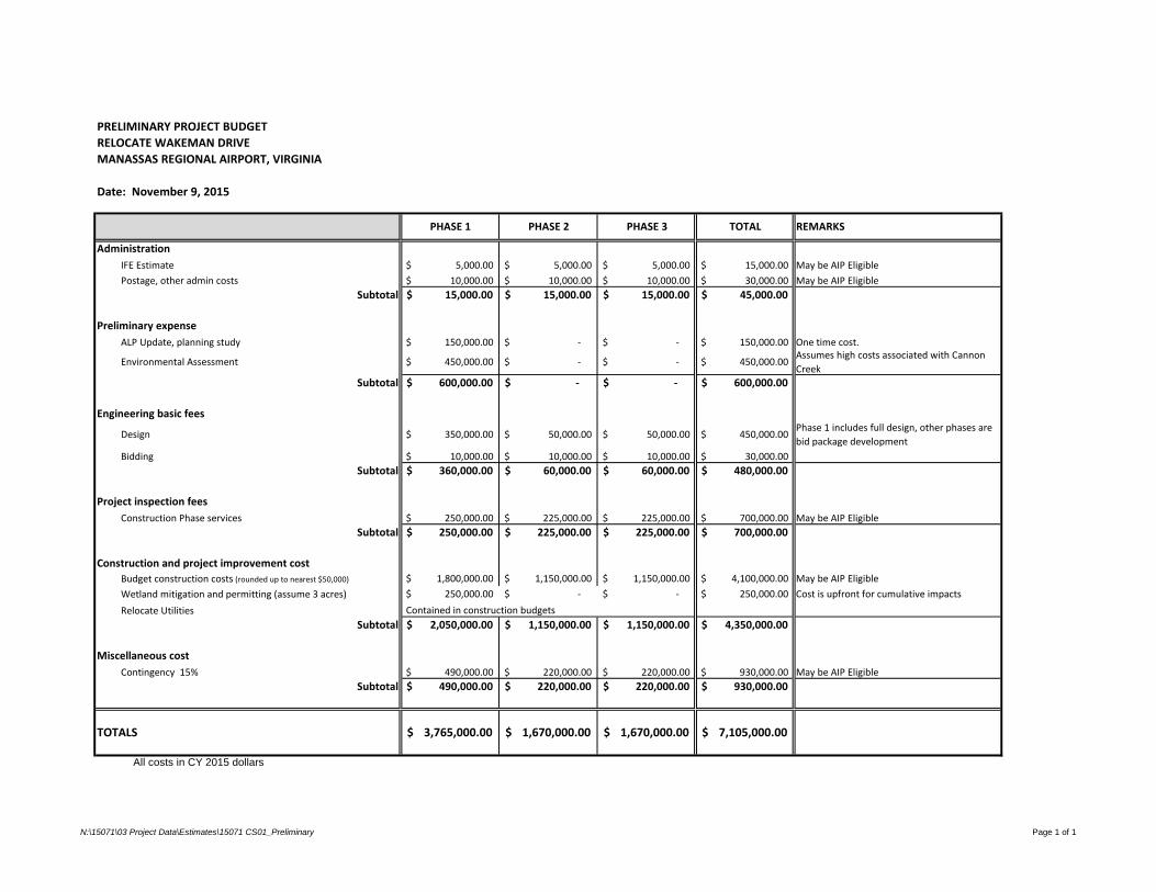
PRELIMINARY PROJECT BUDGET
RELOCATE WAKEMAN DRIVE
MANASSAS REGIONAL AIRPORT, VIRGINIA
Date: November 9, 2015
Administration
IFE Estimate 5,000.00$ 5,000.00$ 5,000.00$ 15,000.00$ May be AIP Eligible
Postage, other admin costs 10,000.00$ 10,000.00$ 10,000.00$ 30,000.00$ May be AIP Eligible
Subtotal 15,000.00$ 15,000.00$ 15,000.00$ 45,000.00$
Preliminary expense
ALP Update, planning study 150,000.00$ -$ -$ 150,000.00$ One time cost.
Environmental Assessment 450,000.00$ -$ -$ 450,000.00$ Assumes high costs associated with Cannon
Creek
Subtotal 600,000.00$ -$ -$ 600,000.00$
Engineering basic fees
Design 350,000.00$ 50,000.00$ 50,000.00$ 450,000.00$ Phase 1 includes full design, other phases are
bid package development
Bidding 10,000.00$ 10,000.00$ 10,000.00$ 30,000.00$
Subtotal 360,000.00$ 60,000.00$ 60,000.00$ 480,000.00$
Project inspection fees
Construction Phase services 250,000.00$ 225,000.00$ 225,000.00$ 700,000.00$ May be AIP Eligible
Subtotal 250,000.00$ 225,000.00$ 225,000.00$ 700,000.00$
Construction and project improvement cost
Budget construction costs (rounded up to nearest $50,000) 1,800,000.00$ 1,150,000.00$ 1,150,000.00$ 4,100,000.00$ May be AIP Eligible
Wetland mitigation and permitting (assume 3 acres) 250,000.00$ -$ -$ 250,000.00$ Cost is upfront for cumulative impacts
Relocate Utilities
Subtotal 2,050,000.00$ 1,150,000.00$ 1,150,000.00$ 4,350,000.00$
Miscellaneous cost
Contingency 15% 490,000.00$ 220,000.00$ 220,000.00$ 930,000.00$ May be AIP Eligible
Subtotal 490,000.00$ 220,000.00$ 220,000.00$ 930,000.00$
TOTALS 3,765,000.00$ 1,670,000.00$ 1,670,000.00$ 7,105,000.00$
All costs in CY 2015 dollars
Contained in construction budgets
REMARKSPHASE 2PHASE 1 PHASE 3 TOTAL
N:\15071\03 Project Data\Estimates\15071 CS01_Preliminary Page 1 of 1

ENGINEER'S OPINION OF PROBABLE COST
RELOCATE WAKEMAN DRIVE
MANASSAS REGIONAL AIRPORT
MANASSAS, VIRGINIA
DELTA PROJECT NO. 15071
DATE (CY 2015 DOLLARS USED)
QTY UNIT PRICE TOTAL QTY UNIT PRICE TOTAL QTY UNIT PRICE TOTAL QTY UNIT PRICE TOTAL
MOBILIZATION (10% OF ALL OTHER COSTS, ROUNDED) LS 1 130,000.00$ 130,000.00$ 1 80,000.00$ 80,000.00$ 1 80,000.00$ 80,000.00$ 1 290,000.00$ 290,000.00$
MISCELLANEOUS DEMOLITION LS 1 10,000.00$ 10,000.00$ 1 10,000.00$ 10,000.00$ 1 10,000.00$ 10,000.00$ 1 30,000.00$ 30,000.00$
CLEARING AND GRUBBING AC 10 5,000.00$ 50,000.00$ 7 5,000.00$ 35,000.00$ 7 5,000.00$ 35,000.00$ 24 5,000.00$ 120,000.00$
UNCLASSIFIED EXCAVATION CY 25,000 8.00$ 200,000.00$ 15,000 8.00$ 120,000.00$ 15,000 8.00$ 120,000.00$ 55,000 8.00$ 440,000.00$
EROSION AND SEDIMENT CONTROL LS 1 50,000.00$ 50,000.00$ 1 50,000.00$ 50,000.00$ 1 50,000.00$ 50,000.00$ 1 150,000.00$ 150,000.00$
SEEDING AND MULCHING AC 10 3,000.00$ 30,000.00$ 7 3,000.00$ 21,000.00$ 7 3,000.00$ 21,000.00$ 24 3,000.00$ 72,000.00$
AGGREGATE BASE, VDOT 21A TN 3,000 30.00$ 90,000.00$ 1,500 30.00$ 45,000.00$ 1,500 30.00$ 45,000.00$ 6,000 30.00$ 180,000.00$
ASPHALT CONCRETE PAVEMENT, SM-9.5A TN 1,100 100.00$ 110,000.00$ 550 100.00$ 55,000.00$ 550 100.00$ 55,000.00$ 2,200 100.00$ 220,000.00$
ASPHALT CONCRETE PAVEMENT, BM-25.0 TN 700 90.00$ 63,000.00$ 350 90.00$ 31,500.00$ 350 90.00$ 31,500.00$ 1,400 90.00$ 126,000.00$
60" RCP, CLASS III (ASSUMED) LF 130 300.00$ 39,000.00$ 130 300.00$ 39,000.00$ 130 300.00$ 39,000.00$ 390 300.00$ 117,000.00$
6" UNDERDRAIN PIPE LF 5,000 10.00$ 50,000.00$ 2,500 10.00$ 25,000.00$ 2,500 10.00$ 25,000.00$ 10,000 10.00$ 100,000.00$
VDOT STD ES-1 EA 2 5,000.00$ 10,000.00$ 2 5,000.00$ 10,000.00$ 2 5,000.00$ 10,000.00$ 6 5,000.00$ 30,000.00$
RIPRAP, CLASS I SY 25 100.00$ 2,500.00$ 25 85.00$ 2,125.00$ 25 85.00$ 2,125.00$ 75 85.00$ 6,375.00$
MISC DRAINAGE (20% OF ALL OTHER DRAINAGE) LS 1 20,000.00$ 20,000.00$ 1 15,000.00$ 15,000.00$ 1 15,000.00$ 15,000.00$ 1 50,000.00$ 50,000.00$
8' GALVANIZED CHAIN LINK FENCE LF 2,500 25.00$ 62,500.00$ 1,200 25.00$ 30,000.00$ 1,200 25.00$ 30,000.00$ 4,900 25.00$ 122,500.00$
AUTOMATIC VEHICLE SLIDING GATE EA 2 10,000.00$ 20,000.00$ 2 10,000.00$ 20,000.00$ 2 10,000.00$ 20,000.00$ 6 10,000.00$ 60,000.00$
PEDESTRIAN GATE EA 2 1,500.00$ 3,000.00$ 2 1,500.00$ 3,000.00$ 2 1,500.00$ 3,000.00$ 6 1,500.00$ 9,000.00$
ACCESS CONTROL SYSTEM UPGRADES LS 1 50,000.00$ 50,000.00$ 1 50,000.00$ 50,000.00$ 1 50,000.00$ 50,000.00$ 1 150,000.00$ 150,000.00$
8" WATER MAIN LF 2,500 80.00$ 200,000.00$ 1,200 80.00$ 96,000.00$ 1,200 80.00$ 96,000.00$ 4,900 80.00$ 392,000.00$
FIRE HYDRANT EA 2 4,500.00$ 9,000.00$ 2 4,500.00$ 9,000.00$ 2 4,500.00$ 9,000.00$ 6 4,500.00$ 27,000.00$
WATER MAIN APPURTENANCES LS 1 25,000.00$ 25,000.00$ 1 25,000.00$ 25,000.00$ 1 25,000.00$ 25,000.00$ 1 75,000.00$ 75,000.00$
SANITARY SEWER LF 2,500 50.00$ 125,000.00$ 1,200 50.00$ 60,000.00$ 1,200 50.00$ 60,000.00$ 4,900 50.00$ 245,000.00$
SANITARY SEWER MANHOLE EA 2 5,000.00$ 10,000.00$ 2 5,000.00$ 10,000.00$ 2 5,000.00$ 10,000.00$ 6 5,000.00$ 30,000.00$
POWER LS 1 50,000.00$ 50,000.00$ 1 50,000.00$ 50,000.00$ 1 50,000.00$ 50,000.00$ 1 150,000.00$ 150,000.00$
TRAFFIC SIGNS LS 1 5,000.00$ 5,000.00$ 1 5,000.00$ 5,000.00$ 1 5,000.00$ 5,000.00$ 1 5,000.00$ 15,000.00$
PAVEMENT MARKING 4" SF 1,700 4.00$ 6,800.00$ 800 4.00$ 3,200.00$ 800 4.00$ 3,200.00$ 3,300 4.00$ 13,200.00$
1,420,800$ 899,825$ 899,825$ 3,220,075$
355,200$ 224,956$ 224,956$ 805,019$
1,780,000$ 1,120,000$ 1,120,000$ 4,030,000$
MISCELLANEOUS
ITEMS
UTILITIES
PHASE 1
UNIT
TOTAL
November 9, 2015
DESCRIPTION
PHASE 2 PHASE 3
TOTAL CONSTRUCTION (rounded)
CONTINGENCY 25%
SUBTOTAL
SECURITY
DRAINAGE
PAVEMENT
TRAFFIC
CONTROL
N:\15071\03 Project Data\Estimates\15071 EST01 Page 1 of 1


