Printed in U.S.A. 6-10 Copyright 2010 Schneider Electric All Rights Reserved. F-27252-3 Selection Guide Note: All performance specifications are nominal and conform to acceptable industry standards. For applications at conditions beyond these specifications, consult Schneider Electric. Schneider Electric shall not be liable for damages resulting from misapplication or misuse of its products. Globe Valve Assemblies The Schneider Electric VA, VF, and VS-7000 and -9000 series Linked Globe Valve Assemblies with Schneider Electric DuraDrive Linear Series Actuators are complete actuator/valve assemblies that accept two position, floating, or proportional control, respectively, from a DDC system or from a thermostat, for control of hot water, chilled water, and steam. These valve assemblies consist of Linear Series spring return Schneider Electric DuraDrive actuators directly mounted on 1/2" up to 4" (15 mm to 80 mm) 2-way and 3-way globe valve bodies. 3-way assemblies are available for mixing (1/2” to 4”) and diverting (1/2” to 2”) applications. The Linear Series Schneider Electric DuraDrive actuators feature linear travel and an integral linkage, eliminating the need for separate linkages. Typical applications include reheat on VAV boxes, fan coil units, hot and chilled water coils in air handling units, unit ventilators, and central system applications. Vx-7xxx-8xx Series Vx-7xxx-59x Series Vx-9xxx-8xx Series Vx-9xxx-59x Series Linked Globe Valve Assemblies with Schneider Electric DuraDrive™ Linear Series Actuators 2-Way Linked Globe Valve Assembly (shown assembly uses Mx51-710x actuator) 3-Way Linked Globe Valve Assembly (shown assembly uses Mx51-720x actuator) 3-Way Linked Flanged Globe Valve Assembly (shown assembly uses Mx61-720x actuator)
Transcript
Selection Guide
Vx-7xxx-8xx SeriesVx-7xxx-59x SeriesVx-9xxx-8xx SeriesVx-9xxx-59x Series
Linked Globe Valve Assemblies withSchneider Electric DuraDrive™ Linear
Globe Valve AssembliesThe Schneider Electric VA, VF, and VS-7000 and -9000 series Linked Globe Valve Assemblies with Schneider Electric DuraDrive Linear Series Actuators are complete actuator/valve assemblies that accept two position, floating, or proportional control, respectively, from a DDC system or from a thermostat, for control of hot water, chilled water, and steam.
These valve assemblies consist of Linear Series spring return Schneider Electric DuraDrive actuators directly mounted on 1/2" up to 4" (15 mm to 80 mm) 2-way and 3-way globe valve bodies. 3-way assemblies are available for mixing (1/2” to 4”) and diverting (1/2” to 2”) applications. The Linear Series Schneider Electric DuraDrive actuators feature linear travel and an integral linkage, eliminating the need for separate linkages.
Typical applications include reheat on VAV boxes, fan coil units, hot and chilled water coils in air handling units, unit ventilators, and central system applications.
Printed in U.S.A. 6-10 Copyright 2010 Schneider Electric All Rights Reserved. F-27252-3
Note: All performance specifications are nominal and conform to acceptable industry standards. For applications at conditions beyond these specifications, consult Schneider Electric. Schneider Electric shall not be liable for damages resulting from misapplication or misuse of its products.
F-27169MA51-710x, MF51-7103, and MS51-7103 105 lbf (467 N) Linear Series Schneider Electric DuraDrive Actuators General Instructions – Sales Personnel
– Application Engineers– Installers– Service Personnel– Start-up Technicians
Describes the actuator’s features, specifications, and possible applications. Provides step-by-step mounting instructions.F-27120
MAx1-720x, MFx1-7203, and MSx1-7203 220 lbf (979 N) Linear Series Schneider Electric DuraDrive Actuators General Instructions
F-27171MA51-710x, MF51-7103, MS51-7103 Linear Series Schneider Electric DuraDrive Actuators Installation Instructions
Describes the actuator’s features and possible applications. Provides step-by-step mounting instructions.
F-27165Mx51-710x, Mx51-720x, and Mx61-720x Schneider Electric DuraDrive Linear Series Spring Return Actuator Submittal Sheet
– Sales Personnel– Application Engineers
Describes features and specifications of the Linear Series Schneider Electric DuraDrive actuators.
F-27167
Vx-7xxx-xxx-x-P and Vx-9xxx-xxx-x-P Two-Way and Three-Way Globe Valve Assemblies with Schneider Electric DuraDrive Linear Series Spring Return Actuators Submittal Sheet
Describes features and specifications of the Globe Valve Assemblies using the Linear Series Schneider Electric DuraDrive actuators.
F-26080 EN-205 Water System Guidelines
– Application Engineers– Installers– Service Personnel– Start-up Technicians
Describes Schneider Electric approved water treatment practices.
F-24380VB-7211 Series 1/2" to 1-1/4" Union Straightway NPT Stem Up Open, 2-Way Valves General Instructions
– Sales Personnel– Application Engineers– Installers– Service Personnel– Start-up Technicians
Describes the valve’s features, specifications, and possible applications. Provides step-by-step mounting, installation, and checkout instructions.
F-26075VB-7213 Series 1/2" to 2" Screwed NPT Stem Up Open, 2-Way Valves General Instructions
F-26077VB-7215 Series 15 mm to 50 mm Screwed Rp Stem Up Open, 2-Way Valves General Instructions
F-24384VB-7221 Series 1/2" to 1-1/4" Union Straightway NPT Stem Up Closed, 2-Way Valves General Instructions
F-26073VB-7223 Series 1/2" to 2" Screwed NPT Stem Up Closed, 2-Way Valves General Instructions
F-26079VB-7225 Series 15 mm to 50 mm Screwed Rp Stem Up Closed, 2-Way Valves General Instructions
F-26074VB-7313 Series 1/2" to 2" Screwed NPT 3-Way Mixing Valves General Instructions
F-26078VB-7315 Series 15 mm to 50 mm Screwed Rp 3-Way Mixing Valves General Instructions
F-26076VB-7323 Series 1/2" to 2" Screwed NPT 3-Way Diverting Valves General Instructions
F-24382VB-9213 Series 2-1/2” to 6” Screwed or Flanged Stem Up Open, 2-Way Valves General Instructions
F-25672VB-9215 Series 65 mm and 80 mm Screwed Stem Up Open, 2-Way Valves General Instructions
F-24386VB-9223 2-1/2” to 6” Screwed or Flanged Stem Up Closed, 2-Way Valves General Instructions
F-25673VB-9225 Series 65 mm and 80 mm Screwed Stem Up Closed, 2-Way Valves General Instructions
F-24393VB-9313 Series 2-1/2” to 6” Screwed or Flanged 3-Way Mixing Valves General Instructions
F-25674VB-9315 Series 65 mm and 80 mm Screwed 3-Way Mixing Valves General Instructions
2 Copyright 2010 Schneider Electric All Rights Reserved. F-27252-3
Features and Benefits
Globe Valve Assembly Selection ProcedureWhen selecting a globe valve assembly, you must determine the applicable codes for the control signal type, valve body configuration, end connection, port size, and actuator. Select a globe valve assembly part number as follows:
1. Control Signal Type, Valve Body Configuration, and End Connection
Referring to “Part Numbering System” on page 4, select the appropriate codes for these part number fields.
2. Valve Size (Flow Coefficient)
If the required flow coefficient (Cv) has not yet been determined, do so as follows:
a. Refer to the “Sizing and Selection” section on pages 8 to 11, to calculate the required Cv.
b. Select the nearest available Cv and corresponding valve body port code from “Part Numbering System” on page 4.
3. Actuator
Select the appropriate actuator and code, according to “Part Numbering System” on page 4, based on the control signal type, required valve normal position, and voltage requirements. For detailed actuator information, refer to the applicable actuator specifications on page 16, 19, or 21.
Note: Globe Valve Assemblies are not available with Mx51-7103-0x0 actuators (equipped with appliance wire). However, if required, you may field-assemble one of these actuators to a globe valve body. For information on Mx51-7103-0x0 actuators, refer to page 16.
4. Close-off Pressure
Confirm in Table-3 or Table-4 that the selected actuator and valve body combination provides sufficient close-off pressure. If no close-off pressure is shown, the valve body/actuator combination is not valid.
5. Available Space
If available space is a consideration, check the appropriate dimensional figure (Figure-8 through Figure-19) and its accom-panying table for any potential fit problems.
Features Benefits24 Vac, 120 Vac, and 230 Vac models. Satisfies a wide range of power requirements.
Compact size. Allows installation in limited spaces.
Spring return. Valve returns to known position upon loss of power.
Manual override. Allows valve positioning and preload adjustment, simplifying installation, start-up, and troubleshooting.
Rugged polymer or die-cast housings rated for up to NEMA 2, UL Type 2 (IP54).
Water-resistant rating supports use in most common indoor HVAC environments.
Valve sizes 1/2" to 4" and 15 mm to 80 mm (Union Straightway, NPT, Flanged, Metric) 2-Way and 3-Way.
Satisfies a wide range of application requirements.
Up to 250 psig (1724 kPa) close-off. Meets variety of close-off requirements.
Built-in position feedback on MFx1-710x floating and all proportional models.
Offers maximum flexibility in selecting precise control for a wide variety of applications, significantly reducing installation time.
High fluid and ambient temperature ratings. Allows use in harsh environments.
Proportional models feature control function switch or jumper.
Allows the selection of direct or reverse action for application flexibility.
Thermal isolation. Protects the actuator from cold or excess heat generated by chilled water, hot water, or steam passing through the valve. Discourages condensation.
Spring-loaded PTFE valve packing. Self adjusting. No tightening required.
250 psig valve body static pressure rating per ANSI Standards (B16.15—1985) for screwed cast bronze bodies. 125 psig valve body static pressure rating for cast iron flanged bodies.
Meets most demanding pressure requirements.
Overload protection on all models. Eliminates application of excessive force on stem and overheating of actuator.
Highly visible position indicator. Shows the valve position, facilitating setup, checkout, and troubleshooting.
24 Vac models require less than 10 VA. Saves cost while meeting job specifications, by using fewer transformers and less energy.
F-27252-3 Copyright 2010 Schneider Electric All Rights Reserved. 3
Linked Globe Valve Assembly
Part Numbering System
Port Code
Control Signal Type
A = Two Position
F = Floating
S = Proportional
Connection
1 = Union Straightway a
2 = Flared End b
3 = Thread NPT
5 = Metric Thread (Rp) c
a 1/2" to 1-1/4" only.b 1/2" only.c 15 to 80 mm only.
Pattern Code
4 = Straightway
5 = Globe Flanged
Linked Globe Valve Assemblies
Actuator
V X - X X X X - X X X - X - X X
Two PositionMA51-7100=801
MA51-7103=N/A d
MA51-7103-100=804
MA51-7101=802
MA51-7200=592
MA51-7201=591
MA51-7203=593
MA61-7200=595
MA61-7201=594
MA61-7203=596
FloatingMF51-7103=N/A d
MF51-7103-100=804
MF51-7203=593
MF61-7203=596
1 The configuration of the valve assembly determines the valve stem position and flow, as shipped from the factory. See the table below.
2-Way 3-Way
Cv
Size Cv P Code Mixing Diverting P Code
1/2" 0.4 1 — —
1.3 2 2.2 2.2 2
2.2 3 — —
4.4 4 4.4 4.4 4
3/4" 5.5 5 — —
7.5 6 7.5 7.5 6
1" 10.0 7 — —
14.0 8 14.0 15.0 8
1-1/4" 20.0 9 20.0 20.0 9
1-1/2" 28.0 10 28.0 28.0 10
2" 40.0 11 41.0 40.0 11
2-1/2" 56.0 12 67e — 12
65.0 12 74f — 12
3" 85.0 13 91e — 13
85.0 13 101f — 13
4" 145.0 14 170 — 14
kvs kvs
15 mm 0.3 1 — —
1.1 2 1.9 — 2
1.9 3 — —
3.8 4 3.8 — 4
20 mm 4.8 5 — —
6.5 6 6.5 — 6
25 mm 8.7 7 — —
12.0 8 12.0 — 8
32 mm 17.0 9 17.0 — 9
40 mm 24.0 10 24.0 — 10
50 mm 35.0 11 36.0 — 11
65 mm 56.0 12 58.0 — 12
80 mm 73.0 13 78.0 — 13
e Threaded valve body.f Flanged valve body.
Valve Assemblies Valve Body Action Factory Shipped Position Action
Valve Stem Flow
VX-721X-XXX-4-P 2-Way Stem Up Open Up Open A to AB Flow decreases as actuator extends
VX-725X-XXX-4-P
VX-727X-XXX-4-P
VX-921X-XXX-X-P
VX-722X-XXX-4-P 2-Way Stem Up Closed Up Closed A to AB Flow increases as actuator extends
VX-726X-XXX-4-P
VX-728X-XXX-4-P
VX-922X-XXX-X-P
VX-731X-XXX-4-P 3-Way Mixing Up B to AB A to AB Flow increases as actuator extends
VX-931X-XXX-X-P B to AB Flow decreases as actuator extends
VX-732X-XXX-4-P 3-Way Diverting Up B to AB B to A Flow increases as actuator extends
B to AB Flow decreases as actuator extends
ProportionalMS51-7103=N/A d
MS51-7103-20=N/A d
MS51-7103-30=N/A d
MS51-7103-40=N/A d
MS51-7103-50=N/A d
MS51-7103-60=N/A d
MS51-7103-100=804
MS51-7103-120=806
MS51-7103-130=808
MS51-7103-140=810
MS51-7103-150=812
MS51-7103-160=814
MS51-7203=593
MS61-7203=596
Configuration
721, 725 = 2-Way, Stem Up Open727, 921
722, 726 = 2-Way, Stem Up Closed728, 922
731, 931 = 3-Way, Mixing
732 = 3-Way, Diverting
1
d Factory assemblies not available.
Purchase actuator and valve body
separately and field assemble.
4 Copyright 2010 Schneider Electric All Rights Reserved. F-27252-3
System Design Considerations
Linked Globe Valve Assemblies
Note: The information in this section describes characteristics of the VB-7xxx and VB-9xxx valve bodies, which are used in the Vx-7xxx and Vx-9xxx valve assemblies.
Control Precision
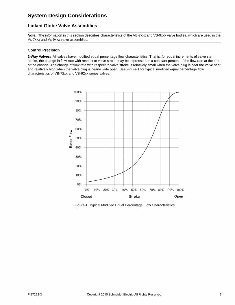
2-Way Valves: All valves have modified equal percentage flow characteristics. That is, for equal increments of valve stem stroke, the change in flow rate with respect to valve stroke may be expressed as a constant percent of the flow rate at the time of the change. The change of flow rate with respect to valve stroke is relatively small when the valve plug is near the valve seat and relatively high when the valve plug is nearly wide open. See Figure-1 for typical modified equal percentage flow characteristics of VB-72xx and VB-92xx series valves.
F-27252-3 Copyright 2010 Schneider Electric All Rights Reserved. 5
3-Way Valves: 3-way mixing valves are designed so that the flow from either of the inlet ports to the outlet is approximately linear, which means the total flow from the outlet is almost constant over the stroke of the valve stem. See Figure-2 for typical flow characteristics of the VB-731x and VB-931x series valve bodies.
Rangeability
Rangeability is the ratio of rated flow to the minimum controllable flow through a valve.
2-Way Valves: Table-1 lists the rangeability for VB-72xx and VB-92xx series globe valves. Refer to the model charts on the following pages for detailed valve information.
3-Way Valves: For mixing valves, control begins as soon as plug displacement allows flow. Thus, the rangeability of 3-way valves normally exceeds 500:1, which is the reciprocal of 0.2% nominal leakage.
Table-1 Rangeability.
Nominal Valve SizePort Code (P)
NominalRangeabilityStandard Metric
1/2" 15 mm
1 5:1
2 15:1
3 25:1
4 40:1
3/4" 20 mm5 50:1
6 60:1
1" 25 mm7 60:1
8 75:1
1-1/4" 32 mm 9 75:1
1-1/2" 40 mm 10 75:1
2" 50 mm 11 75:1
2-1/2” 65 mm 12 75:1
3” 80 mm 13 75:1
4” — 14 75:1
StrokeStem Up Stem Down
0% 20% 40% 60% 80% 100%
Ra
ted
Flo
w100%
90%
80%
70%
60%
50%
40%
30%
20%
10%
0%
"A" Port "B" Port
Figure-2 Typical Flow Characteristics.
6 Copyright 2010 Schneider Electric All Rights Reserved. F-27252-3
Temperature/Pressure Ratings
See Figure-3 for temperature and pressure ratings of 2-way and 3-way valves. Ratings conform with published values and disclaimer.
VB-7xxx-0-x-P and VB-9xxx-0-4-P (Cast Bronze Body)
Standards: Pressure to ANSI B16.15, Class 250, with 400 psi (2758 kPa) up to 150 °F (65 °C), decreasing to 346 psi (2386 kPa) at 281°F (138 °C).
Materials: Valve body is made of bronze, ASTM B584. Valve trim is 316 stainless steel stem with brass, stainless steel, or bronze plug, metal-to-metal or EPDM disc with PTFE packing parts. See Table-5 or Table-6 for further details.
VB-9xxx-0-5-P (Cast Iron Body with Flanged End Fittings)
Standards: Pressure to ANSI B16.1, Class 125, with 200 psi (1379 kPa) up to 150 °F (65 °C), decreasing to 169 psi (1165 kPa) at 281°F (138 °C).
Materials: Valve body is made of cast iron, ASTM A126 Class B. Valve trim is 316 stainless steel stem, brass or bronze plug, metal-to-metal or EPDM disc with PTFE packing parts. See Table-5 or Table-6 for further details.
Close-off Ratings
Nominal actuator close-off ratings are based on ANSI IV (0.01% leakage) with EPDM discs and PTFE discs in steam applications. Metal-to-metal trim such as brass 3-way and high temperature stainless are designed for ANSI III (0.1% leakage). Seat leakage for reduced port versions of metal-to-metal seats may match the full port versions, allowing up to 1% on the 0.4 Cv plugs.
0 50
(345)
100
(689)
150
(1034)
200
(1379)
250
(1724)
300
(2068)
350
(2458)
400
(2758)
400 (204)
340 (171)
300 (149)
281 (138)
200 (93)
150 (65)
100 (38)
50 (10)
0
286
(1973)
321
(2218)
169
(1166)
165
(1138)
Limits for
VB-93X3-0-5
Limits for
VB-92X3-0-5
Limits for
VB-727X, VB-728X
Limits for
VB-725X, VB-726X
Limits for
VB-721X, VB-921X-0-4,
VB-722X, VB-922X-0-4,
VB-73XX, VB-93XX-0-4
Te
mp
era
ture
—°F
(°C
)
Pressure—psig (kPa)
Figure-3 Temperature and Pressure Ratings for VB-7xxx and VB-9xxx Series Globe Valves.
F-27252-3 Copyright 2010 Schneider Electric All Rights Reserved. 7
Installation Considerations
Mounting Angle of Valve Assembly
Be sure to allow the necessary clearance around the valve assembly. The valve assembly must be mounted so that the valve stem is at least 5° above the horizontal. This ensures that any condensate that forms on the valve body will not travel into the linkage or actuator, where it may cause corrosion. On steam applications, where the ambient temperature approaches the limit of the actuator, the valve assembly must be mounted 45° from vertical. See the applicable Actuator General Instructions for details.
Insulation of Linked Globe Valve Assembly
The globe valve should be completely insulated to minimize the effect of heat transfer and condensation at the actuator.
Caution: The actuator and the integral linkage must not be insulated. Doing so will result in excess heat or condensation within the actuator.
Temperature Limits for Globe Valve Assembly
When installing the globe valve assembly, observe the minimum and maximum temperature limits given in the Actuator Specifications and Valve Assembly Mounting Dimensions section of this document.
Sizing and Selection
Flow Coefficient (Cv)
When sizing a valve, you must select a flow coefficient (Cv), which is defined as the flow rate in gallons per minute (GPM) of 60 °F water that will pass through the fully open valve with a 1 psi pressure drop (P). It is calculated according to this formula:
, where P is measured in psi.
Since the flow rate through the heat exchanger is usually specified, the only variable normally available in sizing a valve is the pressure drop. The following information in this section can be used to determine what pressure drop to use in calculating a valve Cv. Once you have calculated the Cv, consult “Part Numbering System” on page 4 to select the valve body having the nearest available Cv.
Note: Metric equivalent.
• The metric measure of flow coefficient is kvs, which is calculated according to the formula: (where P is measured in bar; 1 bar = 100 kPa).
• If the Cv is already known, it may be converted directly to its kvs equivalent: .
Two-position Control
Two-position control valves are normally selected “line size” to keep pressure drop at a minimum. If it is desirable to reduce the valve below line size, then 10% of “available pressure” (that is, the pump pressure differential available between supply and return mains with design flow at the valve location) is normally used to select the valve.
Proportional Control
Proportional control valves are usually selected to take a pressure drop equal to at least 50% of the “available pressure.” As “available pressure” is often difficult to calculate, the normal procedure is to select the valve using a pressure drop at least equal to the drop in the coil or other load being controlled (except where small booster pumps are used) with a minimum recommended pressure drop of 5 psi (34 kPa). When the design temperature drop is less than 60°F (33°C) for conventional heating systems, higher pressure drops across the valve are needed for good results (Table-2).
Secondary Circuits with Small Booster Pumps: 50% of available pressure difference (equal to the drop through load, or 50% of booster pump head).
Table-2 Conventional Heating System.
Design TemperatureLoad Drop °F (°C)
Recommended Pressure Dropa
(% of Available Pressure)
a Recommended minimum pressure drop = 5 psi (34 kPa).
Multiplier onLoad Drop
60 (33) or More 50% 1 x Load Drop
40 (22) 66% 2 x Load Drop
20 (11) 75% 3 x Load Drop
Cvgpm
P-----------=
kvsm
3h
P---------------=
kvs
Cv
1.156---------------=
8 Copyright 2010 Schneider Electric All Rights Reserved. F-27252-3
3-Way Proportional Mixing Valves Used to Bypass Flow
When 3-way proportional linked globe valve assemblies are used to control flow through a heating or cooling coil, the valve assembly is piped on the outlet side of the load to throttle the water flow through the load, and therefore control the heat output of the load (Figure-4).
3-Way Proportional Mixing Valves Used to Blend Water Flows
Proportional 3-way mixing valves used to blend two water flows (Figure-5) control the heat output by varying the water temperature to the load at constant flow. These valves do not require high pressure drops for good control results. They can be sized for a pressure drop of 20% of the “available pressure” or equal to 25% of the pressure drop through the load at full flow.
Coil
ReturnBypass
Supply
Stem down = flow through coil.Stem up = flow through coil bypass.
Coil
Return
Bypass
Supply
Stem up = flow through coil.Stem down = flow through coil bypass.
ValveAssembly
AB
AB
RL
L
ValveAssembly
AB
AB
RL
L
Figure-4 Typical Piping of 3-Way Mixing Valve for Control of Heating or Cooling Coil.
BoilerReturn
Bypass
AB
AB
Coil
Return Supply
Supply
AB
AB
Typical Boiler Hot Water Reset Typical Primary-Secondary Piping
SystemPump
FromOtherZones
BalancingCock
BalancingCock
To OtherZones
ValveAssembly
AB
AB
RL
L
ValveAssembly
AB
AB
RL
L
Figure-5 Typical 3-Way Mixing Valve Piping for Proportional Control Used to Blend Two Water Flows.
F-27252-3 Copyright 2010 Schneider Electric All Rights Reserved. 9
3-Way Diverting Valves
Proportional and two-position 3-way diverting linked globe valve assemblies are used to control the flow of hot or chilled fluids in heating systems, cooling coils, or other load by diverting the flow to either the load or a bypass. The valve must be piped with one inlet and two outlets. (Figure-6).
HeatExchanger
Return
AB
AB
Supply
ValveAssembly
AB
AB
RL
L
Figure-6 Typical 3-Way Diverting Valve Piping.
10 Copyright 2010 Schneider Electric All Rights Reserved. F-27252-3
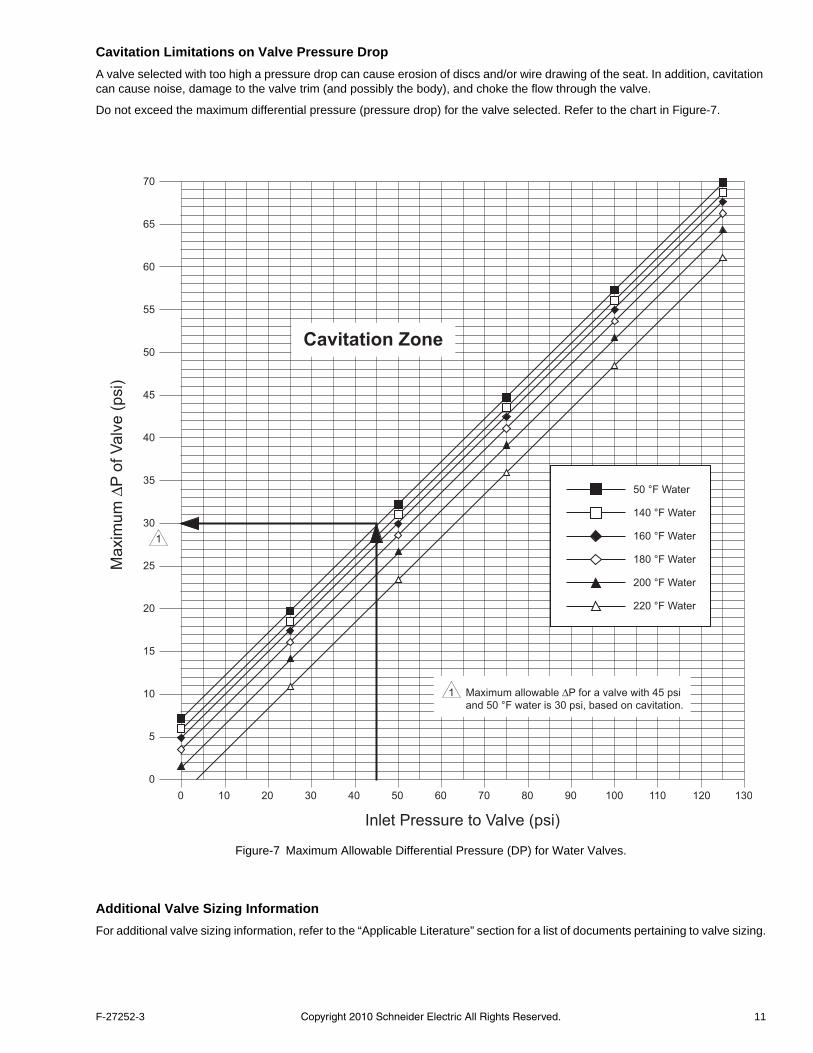
Cavitation Limitations on Valve Pressure Drop
A valve selected with too high a pressure drop can cause erosion of discs and/or wire drawing of the seat. In addition, cavitation can cause noise, damage to the valve trim (and possibly the body), and choke the flow through the valve.
Do not exceed the maximum differential pressure (pressure drop) for the valve selected. Refer to the chart in Figure-7.
Additional Valve Sizing Information
For additional valve sizing information, refer to the “Applicable Literature” section for a list of documents pertaining to valve sizing.
70
65
60
55
50
45
40
35
30
25
20
15
10
5
0
0 10 20 30 40 50 60 70 80 90 100 110 120 130
Ma
xim
um
ΔP
of V
alv
e (
psi)
Inlet Pressure to Valve (psi)
50 °F Water
140 °F Water
160 °F Water
180 °F Water
200 °F Water
220 °F Water
Cavitation Zone
1
1 Maximum allowable ΔP for a valve with 45 psi
and 50 °F water is 30 psi, based on cavitation.
Figure-7 Maximum Allowable Differential Pressure (DP) for Water Valves.
F-27252-3 Copyright 2010 Schneider Electric All Rights Reserved. 11
Valve/Actuator Combinations
2-Way Linked Globe Valve Assemblies with Linear Series Actuators
Note: Choose a valve assembly having a close-off pressure capability sufficient for the application. Not all valve body and actuator combinations are available factory-assembled. Some combinations must be field-assembled.
Table-3 2-Way Linked Globe Valve Assemblies with Linear Series Spring Return Actuators — Selection Chart.
2-Way Linked Globe Valve Assemblies
Actuator Force Rating
105 lbf (467 N) 220 lbf (979 N)
Actuator Model (Actuator Code)
Two-PositionMA51-710x (801) (802)MA51-7103 (N/A)a
MA51-7103-100 (804)
FloatingMF51-7103 (N/A)a
MF51-7103-100 (804)
ProportionalMS51-7103 (N/A)a
MS51-7103-0x0 (N/A)a
MS51-7103-1x0 (804) (806)(808) (810) (812) (814)
a Models without actuator codes are not offered as factory assemblies. Purchase the actuator and the valve body separately and field assemble. For available factory assemblies, consult the price schedule.
Two-PositionMA51-720x (591)(592) (593)
FloatingMF51-7203 (593)
ProportionalMS51-7203 (593)
Two-PositionMA61-720x (594)(595) (596)
FloatingMF61-7203 (596)
ProportionalMS61-7203 (596)
Valve AssemblyPart Number b
b To determine a specific part number, see "Part Numbering System" on page 4.
PCode
Valve Sizein. (mm)
Cvc
c (where P is measured in psi) kvs = Cv / 1.156 (where P is measured in bar; 1 bar = 100 kPa).
kvsb
Actuator Close-off Pressure pside
d Close-off ANSI IV (.01%) for soft seats. For seat leakage ratings of specific valve bodies, see Table-5 and Table-6.e Close-off pressure ratings describe only the differential pressure which the actuator can close-off with adequate seating force. Consult valve body specifications
for other limitations. The rating value is the pressure difference between the inlet and outlet ports.
N.O.f
f Normally open (N.O.) assembly using stem up open valve body. See "Part Numbering System" on page 4.
N.C.g
g Normally closed (N.C.) assembly using stem up closed valve body. See "Part Numbering System" on page 4.
12 Copyright 2010 Schneider Electric All Rights Reserved. F-27252-3
3-Way Linked Globe Valve Assemblies with Linear Series Actuators
Note: Choose a valve assembly having a close-off pressure capability sufficient for the application. Not all valve body and actuator combinations are available factory-assembled. Some combinations must be field-assembled.
Table-4 3-Way Linked Globe Valve Assemblies with Linear Series Spring Return Actuators — Selection Chart.
3-Way Linked Globe Valve Assembliesa
a Refer to Figure-4, Figure-5, and Figure-6 for typical piping diagrams for 3-way linked globe valve assemblies.
Actuator Force Rating
105 lbf (467 N) 220 lbf (979 N)
Actuator Model (Actuator Code)
Two-PositionMA51-710x (801) (802)MA51-7103 (N/A)b
MA51-7103-100 (804)
FloatingMF51-7103 (N/A)b
MF51-7103-100 (804)
ProportionalMS51-7103 (N/A)b
MS51-7103-0x0 (N/A)b
MS51-7103-1x0 (804) (806)(808) (810) (812) (814)
b Models without actuator codes are not offered as factory assemblies. Purchase the actuator and the valve body separately and field assemble. For available factory assemblies, consult the price schedule.
Two-PositionMA51-720x (591)(592) (593)
FloatingMF51-7203 (593)
ProportionalMS51-7203 (593)
Two-PositionMA61-720x (594)(595) (596)
FloatingMF61-7203 (596)
ProportionalMS61-7203 (596)
Valve AssemblyPart Number c
c To determine a specific part number, see "Part Numbering System" on page 4.
PCode
Valve Sizein. (mm)
Cvd
d (where P is measured in psi) kvs = Cv / 1.156 (where P is measured in bar; 1 bar = 100 kPa).
kvsc Actuator Close-off Pressure psiae
e Close-off pressure ratings describe only the differential pressure which the actuator can close-off with adequate seating force. Consult valve body specifications for other limitations. The rating value is the pressure difference between the inlet and outlet ports.
MixingVx-7313-xxx-4-PVx-7315-xxx-4-Pf
f Metric thread 15 to 80 mm (Rp 1/2 to Rp 3).
21/2 (15)
2.2 1.9250
—
—
4 4.4 3.8
6 3/4 (20) 7.5 6.5 200
8 1 (25) 14.0 12.0 90
9 1-1/4 (32) 20.0 17 60 150
10 1-1/2 (40) 28 24 35 100
11 2 (50) 41 36 20 65
DivertingVx-7323-xxx-4-P
4 1/2 (15) 4.4 3.8
250
—
—
6 3/4 (20) 7.5 6.5
8 1 (25) 15.0 13.0
9 1-1/4 (32) 20.0 17.3
25010 1-1/2 (40) 28 24.2
11 2 (50) 40 34.6
Vx-9313-xxx-4-Pg
Vx-9313-xxx-5-Ph
Vx-9315-xxx-4-Pf
12 2-1/2 (65)67.0g
g Threaded valve body.
58g
— —
3374.0h
h Flanged valve body.
64h
13 3 (80)91.0g 79g
22101.0h 87h
Vx-9313-xxx-5-Ph 14 4 (N/A) 145.0 125 — — 12
Cvgpm
P-----------= kvs
m3
hP
---------------=
F-27252-3 Copyright 2010 Schneider Electric All Rights Reserved. 13
Globe Valve Body Specifications
Table-5 Specifications for 1/2” to 2” VB-7xxx Series and 2-1/2” and 3” VB-9xxx Series Globe Valve Bodies .
SpecificationsNPT, Rp Screwed Valve Bodies
2-Way 3-Way
Applications Chilled or Hot Water, or Steam Chilled or Hot Water
Type of End Fitting NPT, Rp Screwed, Flared, Union Straightway NPT, Rp Screwed, Flared
SizeVB-7xxx Series 1/2" through 2" (15 mm through 50 mm)
VB-9xxx Series 2-1/2" and 3" (65 mm and 80 mm)
Action Stem Up Open or Stem Up Closed Mixing or Diverting
Valve Body Seriesa
a To determine a specific part number, see the Linked Globe Valve Assembly Part Numbering System.
Vx-72xx-0-4-PVx-92xx-0-4-P
Vx-73xx-0-4-PVx-93xx-0-4-P
Flow Type Equal Percentageb
b See "2-Way Valves" on page 5 or "3-Way Valves" on page 6 for a detailed description of the flow
250 psig (1724 kPa), up to 400 psig(2758 kPa) below 150 °F (66 °C)c
c Do not apply the above pressure rating to the piping system.
250 psig (1724 kPa), up to 400 psig(2758 kPa) below 150 °F (66 °C)c
Pressure Class (VB-7xx5) PN16 PN16
Rangeability See Table-1 500:1
Seat Leakage
ANSI Class IV (.01%) (VB-721x,VB-722x, VB-725x, VB-727x) ANSI Class III (0.1%)
ANSI Class III (0.1%) (VB-727x, VB-728x)
STEAM
Inlet Pressure — Maximum 35 psig (241 kPa) —
Fluid Temperature — Maximum
281 °F (138 °C) (VB-721x)
—340 °F (171 °C) (VB-725x, VB-726x)
400 °F (205 °C) (VB-727x, VB-728x)
Allowable Differential Pressured
d Maximum recommended differential pressure. Do not exceed the recommended differential pressure (pressure drop) or the integrity of valve parts may be affected. Exceeding the maximum recommended differential pressure voids the product warranty.
20 psi (138 kPa) —
WATER
Fluid Temperature — Minimum1/2” through 2” 20 °F (-7 °C)
2-1/2” and 3” 40 °F (4 °C)1/2” through 2” 20 °F (-7 °C)
2-1/2” and 3” 40 °F (4 °C)
Fluid Temperature — Maximum 1/2” through 3” 281 °F (138 °C) 1/2” through 3” 300 °F (149 °C)
Allowable Differential Pressured35 psi (241 kPa) Max. for Normal Lifespan
(refer to “Cavitation Limitations on Valve Pressure Drop”, on page 18)
35 psi (241 kPa) Max. for Normal Lifespan(refer to “Cavitation Limitations on Valve Pressure
Drop”, on page 18)
14 Copyright 2010 Schneider Electric All Rights Reserved. F-27252-3
Table-6 Specifications for Flanged 2-1/2” to 4” Vx-9xxx Series Globe Valve Bodies.
SpecificationsFlanged Valve Bodies
2-Way 3-Way
Applications Chilled or Hot Water, or Steam Chilled or Hot Water
Type of End Fitting Flanged Flanged
Size 2-1/2 in. through 4 in. 2-1/2 in. through 4 in.
Action Stem Up Open or Stem Up Closed Mixing
Valve Assembly Series Vx-92xx-0-5-P Vx-931x-0-5-P
Flow Type Equal Percentagea
a See "2-Way Valves" on page 5 or "3-Way Valves" on page 6 for a detailed description of the flow.
Seat Leakage ANSI Class IV (.01%) ANSI Class III (0.1%)
STEAM
Inlet Pressure — Maximum 35 psig (241 kPa)
—Fluid Temperature — Maximum 281 °F (138 °C)
Allowable Differential Pressurec
c Maximum recommended differential pressure. Do not exceed the recommended differential pressure (pressure drop) or the integrity of valve parts may be affected. Exceeding the maximum recommended differential pressure voids the product warranty.
Fluid Temperature — Maximum 281 °F (138 °C) 300 °F (149 °C)
Allowable Differential Pressurec35 psi (241 kPa) Max. for Normal Lifespan(refer to "Cavitation Limitations on Valve
Pressure Drop" on page 11)
35 psi (241 kPa) Max. for Normal Lifespan(refer to "Cavitation Limitations on Valve
Pressure Drop" on page 11)
F-27252-3 Copyright 2010 Schneider Electric All Rights Reserved. 15
Actuator Specifications and Valve Assembly Mounting Dimensions
Valve Assemblies with MA51-710x, MF51-7103, and MS51-71031/2” (13 mm) Stroke 105 lbf (467 N) Linear Series Schneider Electric DuraDrive Actuators
Actuator Specifications Inputs
Control SIgnal andPower Requirements
All 24 Vac circuits are Class 2. All circuits 30 Vac and above are Class 1
Connections Connecting wiring:
Mx51-710x-0x0 — Appliance wire, 3 ft. (0.9 m) long.Mx51-710x-1x0 — Plenum cable, 3 ft. (0.9 m) long.
Conduit connectors: Enclosure accepts 1/2” (13 mm) conduit connectors. For M20 metric connector, use AM-756 adaptor.
Motor Type Brush DC motor.
Outputs
Electrical Position feedback voltage (MF51-7103-xxx and MS51-7103-xxx):For voltage ranges, the feedback signal is the same range as the input signal. The 0-20 mAdc current range and floating actuators have a 2-10 Vdc position feedback signal. The position feedback signal can supply up to 0.5 mA to operate up to four additional slave actuators.
Mechanical Output force rating: 105 lbf (467 N).
Linear stroke: 1/2” (13 mm) nominal.
Timing
Manual override: Allows valve positioning and preload adjustment, using manual crank.
Reverse acting/direct acting jumper (MS51-7103-xxx): Permits reverse acting or direct acting linear motion.
Part NumberApproximate Stroke Timing in Seconds @ 70 °F (21 °C)a
a Timing was measured with the actuator mounted onto a VB-7xxx series valve.
Powered Spring Return
MA51-710x-xxx 27 19
MF51-710x-xxx60 16
MS51-710x-xxx
16 Copyright 2010 Schneider Electric All Rights Reserved. F-27252-3
Environment
Temperature Limits Shipping and storage: -40 to 160 °F (-40 to 71 °C) ambient.Operating: -22 to 140 °F (-30 to 60 °C) ambient.Temperature restrictions: For maximum ambient of 140 °F (60 °C), maximum fluid temperature must not exceed 366 °F (186 °C).
Humidity 5 to 95% RH, non-condensing.
Locations NEMA 2, UL Type 2 (IEC IP54) with customer-supplied watertight conduit connectors.
Agency Listings (Actuator)
UL UL-873, Underwriters Laboratories (File #E9429 Category Temperature-indicating and Regulating Equipment).
cUL UL Listed for use in Canada by Underwriters Laboratories. Canadian Standards C22.2 No. 24-93.
European Community EMC Directive (89/336/EEC). Low Voltage DIrective (72/23/EEC).
Australia This product meets requirements to bear the C-Tick Mark according to the terms specified by the Communications Authority under the Radiocommunications Act 1992.
Actuator Specifications (Continued)
Dimensions — 1/2” to 2” Globe Valve Assemblies
Valve AssemblyPart Number
ValveSizein.
Valve Dimensions in inches (millimetres)
2-Way (Refer to Figure-8, Figure-10, and Figure-11) 3-Way (Refer to Figure-9 and Figure-12)
F-27252-3 Copyright 2010 Schneider Electric All Rights Reserved. 17
Figure-8 Mx51-710x with 2-Way Globe Valve. Figure-9 Mx51-710x with 3-Way Globe Valve.
Figure-10 Mx51-710x with 2-Way Union Straightway Globe Valve.
Figure-11 Mx51-710x with 2-Way Flared Globe Valve.
Figure-12 Mx51-710x with 3-Way Flared Globe Valve.
CA
J
E
6-5/16
(160)
3-1/2
(89)
6-49/64
(172)
A C
E
6-5/16
(160)
J
3-1/2
(89)
6-49/64
(172)
Flow
A
BC
E
J
6-5/16
(160)
3-1/2
(89)6-49/64
(172)
A C
E
J
6-5/16
(160)
3-1/2
(89)
6-49/64
(172)
A
E
C
J
6-5/16
(160)
6-49/64
(172)
3-1/2
(89)
18 Copyright 2010 Schneider Electric All Rights Reserved. F-27252-3
Valve Assemblies with MA51-720x, MF51-7203, and MS51-72031/2” (13 mm) Nominal Stroke 220 lbf (979 N) Linear Series Schneider Electric DuraDrive Actuators
Actuator Specifications Inputs
Control SIgnal andPower Requirements
All 24 Vac circuits are Class 2. All circuits 30 Vac and above are Class 1
Connections Connecting wiring: Appliance cable, 3 ft. (91 cm) long.
Conduit connectors: Enclosure accepts 1/2” (13 mm) conduit connectors. For M20 metric connector, use AM-756 adaptor.
Motor Type Brushless DC.
Outputs
Electrical Position feedback voltage (MS51-7203): 2-10 Vdc (max. 0.5 mA) output signal for position feedback or to operate up to four additional slave actuators.
Mechanical Output force rating: 220 lbf (979 N).
Linear stroke: 1/2” (13 mm) nominal.
Timing @ 70 °F (21 °C): Approximately 100 seconds powered; 35 seconds spring return. Measured with no load applied to actuator.
Manual override: Allows valve positioning and preload adjustment, using manual crank.
Right/left switch (MS51-7203): Permits reverse acting or direct acting linear motion.
Environment
Temperature Limits Shipping and storage: -40 to 160 °F (-40 to 71 °C) ambient.Operating: 0 °F (-18 °C) to maximum ambient shown in table below.Temperature restrictions
Humidity 15 to 95% RH, non-condensing.
Locations NEMA 2, UL Type 2 (IEC IP54) with customer-supplied watertight conduit connectors.
Part Number
ControlSignal
Power Input
Voltage
RunningDC
Amps
Holding
50 Hz 60 Hz 50/60 Hz
VA W VA W W
MA51-7200
Two-positionSPST orTriacs
120 Vac ±10%50/60 Hz
11.7 8.8 10.0 8.4 — 3.6/5.0
MA51-7201230 Vac ±10%
50/60 Hz15.5 9.5 10.6 8.5 — 4.6/3.3
MA51-720324 Vac ±20%22 to 30 Vdc
9.8 7.5 9.7 7.5 0.29 2.8
MF51-7203Floating Point
SPDT or Triacsa
a 500 mA rated.
24 Vac ±20%22 to 30 Vdc
9.8 7.7 9.7 7.7 0.30 3.3
MS51-7203Proportional
2-10 Vdc or 4-20 Vdcb
b 4-20 mAdc control signal requires the addition of a 500 resistor.
9.8 7.4 9.7 7.4 0.28 2.9
Part Number Max. Allowable Ambient@ Max. Fluid TemperaturesActuator Valve Assembly
F-27252-3 Copyright 2010 Schneider Electric All Rights Reserved. 19
Agency Listings (Actuator)
UL UL-873, Underwriters Laboratories (File #E9429 Category Temperature-indicating and Regulating Equipment).
cUL UL Listed for use in Canada by Underwriters Laboratories. Canadian Standards C22.2 No. 24-93.
European Community EMC Directive (89/336/EEC). Low Voltage DIrective (72/23/EEC).
Australia This product meets requirements to bear the C-Tick Mark according to the terms specified by the Communications Authority under the Radiocommunications Act 1992.
Dimensions — 1/2” to 2” Globe Valve Assemblies
Valve AssemblyPart Number
ValveSizein.
Valve Dimensions in inches (millimetres)
2-Way (Refer to Figure-13) 3-Way (Refer to Figure-14)
Figure-13 Mx51-720x with 1/2” to 2” 2-Way Globe Valve. Figure-14 Mx51-720x with 1/2” to 2” 3-Way Globe Valve.
Actuator Specifications (Continued)
2-9/16
(65)
10-5/8
(270)
C
4-1/16
(103)
6-15/16
(176)
A
J
E
CA
E
2-9/16
(65)
10-5/8
(270)
4-1/16
(103)
6-15/16
(176)
J
20 Copyright 2010 Schneider Electric All Rights Reserved. F-27252-3
Valve Assemblies with MA61-720x, MF61-7203, and MS61-72031” (25 mm) Nominal Stroke 220 lbf (979 N) Linear Series DuraDrive Actuators
Actuator Specifications Inputs
Control SIgnal andPower Requirements
All 24 Vac circuits are Class 2. All circuits 30 Vac and above are Class 1
Connections Connecting wiring: Appliance cable, 3 ft. (91 cm) long.
Conduit connectors: Enclosure accepts 1/2” (13 mm) conduit connectors. For M20 metric connector, use AM-756 adaptor.
Motor Type Brushless DC.
Outputs
Electrical Position feedback voltage (MS61-7203): 2-10 Vdc (max. 0.5 mA) output signal for position feedback or to operate up to four additional slave actuators.
Mechanical Output force rating: 220 lbf (979 N) minimum; 495 lbf (2202 N) maximum stall.
Linear stroke: 1” (25 mm) nominal.
Timing @ 70 °F (21 °C): Approximately 190 seconds powered; 40 seconds spring return. Measured with no load applied to actuator.
Manual override: Allows valve positioning and preload adjustment, using manual crank.
Right/left switch (MS61-7203): Permits reverse acting or direct acting linear motion.
Environment
Temperature Limits Shipping and storage: -40 to 160 °F (-40 to 71 °C) ambient.Operating: 0 °F (-18 °C) to maximum ambient shown in table below.Temperature restrictions
Humidity 15 to 95% RH, non-condensing.
Locations NEMA 2, UL Type 2 (IEC IP54) with customer-supplied watertight conduit connectors.
Agency Listings (Actuator)
UL UL-873, Underwriters Laboratories (File #E9429 Category Temperature-indicating and Regulating Equipment).
cUL UL Listed for use in Canada by Underwriters Laboratories. Canadian Standards C22.2 No. 24-93.
European Community EMC Directive (89/336/EEC). Low Voltage DIrective (72/23/EEC).
Australia This product meets requirements to bear the C-Tick Mark according to the terms specified by the Communications Authority under the Radiocommunications Act 1992.
Part Number
ControlSignal
Power Input
Voltage
RunningDC
Amps
Holding
50 Hz 60 Hz 50/60 Hz
VA W VA W W
MA61-7200
Two-positionSPST orTriacs
120 Vac ±10%50/60 Hz
11.7 8.8 10.0 8.4 — 3.6/5.0
MA61-7201230 Vac ±10%
50/60 Hz15.5 9.5 10.6 8.5 — 4.6/3.3
MA61-720324 Vac ±20%22 to 30 Vdc
9.8 7.5 9.7 7.5 0.29 2.8
MF61-7203Floating Point
SPDT orTriacsa
a 500 mA rated.
24 Vac ±20%22 to 30 Vdc
9.8 7.7 9.7 7.7 0.30 3.3
MS61-7203Proportional2-10 Vdc or4-20 Vdcb
b 4-20 mAdc control signal requires the addition of a 500 resistor.
9.8 7.4 9.7 7.4 0.28 2.9
Part Number Max. Allowable Ambient@ Max. Fluid TemperaturesActuator Valve Assembly
Mx61-720xVx-9xxx-59x-4-PVx-9xxx-59x-5-P
140 °F (60 °C) @ 300 °F (149 °C)
F-27252-3 Copyright 2010 Schneider Electric All Rights Reserved. 21
Dimensions — 2-1/2” and 3” Screwed Globe Valve Assemblies
Valve AssemblyPart Number
ValveSizein.
Valve Dimensions in inches (millimetres)
2-Way (Refer to Figure-15) 3-Way (Refer to Figure-16)
A C E J A C E J
NPT/Metric Thread2-1/2
8-1/2 (216)
3-13/16 (97)
13-15/16 (354)
13-9/16 (344)
8-1/2 (216) 4-5/8 (117)13-15/16
(354)13-9/16 (344)2-Way (N.O.)
Vx-9213-59x-4-PVx-9215-59x-4-P
2-Way (N.C.)Vx-9223-59x-4-PVx-9225-59x-4-P
3-WayVx-9313-59x-4-PVx-9315-59x-4-P 3
9-1/2 (241)
4-1/4 (108)
14-1/4 (362)
13-5/8 (346)
9-1/2 (241) 5 (127)14-1/4 (362)
13-5/8 (348)
A
C
E
2-9/16
(65)
10-5/8
(270)
9-9/16
(243)4-1/16
(103)
J
Figure-15 Mx61-720x with 2-1/2” or 3” 2-Way Screwed Globe Valve.
A
C
E
2-9/16
(65)
10-5/8
(270)
9-9/16
(243)4-1/16
(103)
J
Figure-16 Mx61-720x with 2-1/2” or 3” 3-Way Screwed Globe Valve.
22 Copyright 2010 Schneider Electric All Rights Reserved. F-27252-3
Dimensions — 2-1/2” to 4” Flanged Globe Valve Assemblies
Valve AssemblyPart Number
ValveSizein.
Valve Dimensions in inches (millimetres)
2-Way (Refer to Figure-17) 3-Way (Refer to Figure-19)
A C E F G J A C E F G J
ASA Flanged2-Way (N.O.)
Vx-9213-59x-5-P3-Way
Vx-9313-59x-5-P
2-1/28-1/2 (216)
3-1/2 (89)
13 (330) 7 (178)5-1/2 (140)
13-5/8 (346)
8-1/2 (216)
5-3/8 (137)
13-3/4 (349)
7 (178)5-1/2 (140)
13-5/8 (346)
39-1/2 (241)
3-3/4 (95)
14-1/2 (368)
7-1/2 (191)
6 (152)14-1/8 (359)
9-1/2 (241)
6-3/8 (162)
14 (356)7-1/2 (191)
6 (152)14-1/8 (359)
411-1/2 (292)
4-1/2 (114)
15-3/8 (391)
9 (229)7-1/2 (191)
15-1/8 (384)
11-1/2 (292)
8-1/2 (216)
14-3/4 (375)
9 (229)7-1/2 (191)
15-1/8 (384)
ASA Flanged2-Way (N.C.)
Vx-9223-59x-5-P
2-1/28-1/2 (216)
4 (107)12-3/8 (314)
7 (178)5-1/2 (140)
13-5/8 (346)
—39-1/2 (241)
5 (127)12-5/8 (320)
7-1/2 (191)
6 (152)14-1/8 (359)
411-1/2 (292)
7-1/8 (181)
13-3/8 (340)
9 (229)7-1/2 (191)
15-1/8 (384)
A
J
C
F
E4-1/16
(103)
9-9/16
(243)
10-5/8
(270)
G
2-9/16
(65)
Figure-17 Mx61-720x with 2-1/2” to 4” N.O. 2-Way Flanged Globe Valve.
F-27252-3 Copyright 2010 Schneider Electric All Rights Reserved. 23
A
J
4-1/16
(103)
9-9/16
(243)
10-5/8
(270)
C
F
E
G
2-9/16
(65)
Figure-18 Mx61-720x with 2-1/2” to 4” N.C. 2-Way Flanged Globe Valve.
A
J
C
F
E
4-1/16
(103)
9-9/16
(243)
10-5/8
(270)
G
2-9/16
(65)
Figure-19 Mx61-720x with 2-1/2” to 4” 3-Way Flanged Globe Valve.
Copyright 2010, Schneider ElectricAll brand names, trademarks and registered trademarks are the property of their respective owners. Information contained within this document is subject to change without notice.
F-27252-3www.schneider-electric.com/buildings
Schneider Electric1354 Clifford AvenueP.O. Box 2940Loves Park, IL 61132-2940
On October 1st, 2009, TAC became the Buildings business of its parent company Schneider Electric. This document reflects the visual identity of Schneider Electric, howeverthere remains references to TAC as a corporate brand in the body copy. As each document is updated, the body copy will be changed to reflect appropriate corporate brandchanges.