89
1 School of Computing UNIT – I Software Defined Networks – SCSA 3003
1
School of Computing
UNIT – I
Software Defined Networks – SCSA 3003
2
UNIT 1 INTRODUCTION
How SDN Works – History and Evolution of Software Defined Networking (SDN)-Separation of
Control Plane and Data Plane, IETF Forces, Active Networking.
1. Traditional Networking
Networking has always been very traditional. We have specific network devices like routers, switches,
and firewalls that are used for specific tasks.
These network devices are sold by networking vendors like Cisco and often use proprietary hardware.
Most of these devices are primarily configured through the CLI, although there are some GUI products
like CCP (Cisco Configuration Protocol) for the routers or ASDM for the Cisco ASA firewalls.
A network device, for example, a router has different functions that it has to perform. Think for a
moment about some of the things that a router has to do in order to forward an IP packet:
It has to check the destination IP address in the routing table in order to figure out where to
forward the IP packet to.
Routing protocols like OSPF, EIGRP or BGP are required to learn networks that are installed in
the routing table.
It has to use ARP to figure out the destination MAC address of the next hop or destination and
change the destination MAC address in the Ethernet frame.
The TTL (Time to Live) in the IP packet has to be decreased by 1 and the IP header checksum
has to be recalculated.
The Ethernet frame checksum has to be recalculated.
All these different tasks are separated by different planes. There are three planes:
control plane
data plane
management plane
Let‘s take a look at the difference between these three planes…
Control Plane

3
The control plane is responsible for exchanging routing information, building the ARP table, etc. Here
are some tasks that are performed by the control plane.
Learning MAC addresses to build a switch MAC address table.
Running STP to create a loop-free topology.
Building ARP tables.
Running routing protocols like OSPF, EIGRP, and BGP and building the routing table.
Data Plane
The data plane is responsible for forwarding traffic. It relies on the information that the control plane
supplies. Here are some tasks that the data plane takes care of:
Encapsulate and de-encapsulate packets.
Adding or removing headers like the 802.1Q header.
Matching MAC addresses for forwarding.
Matching IP destinations in the routing table.
Change source and destination addresses when using NAT.
Dropping traffic because of access-lists.
The tasks of the data plane have to be performed as fast as possible which is why the forwarding of
traffic is performed by specialized hardware like ASICs and TCAM tables.
Management Plane
The management plane is used for access and management of our network devices. For example,
accessing our device through telnet, SSH or the console port.
When discussing SDN, the control and data plane are the most important to keep in mind. Here‘s an
illustration of the control and data plane to help you visualize the different planes as shown in figure 1.1

4
Figure 1.1 Control and Data Plane
Above you can see the control plane where we use routing protocols like OSPF and EIGRP and some
static routing. The best routes are installed in the routing table. Another table that the router has to build
is the ARP table.
Information from the routing and ARP table is then used to build the forwarding table. When the router
receives an IP packet, it will be able to forward it quickly since the forwarding table has already been
buil
Let‘s consider some of the things we have to configure on our network to make this happen:
The VLANs have to be created on all switches.
We have to configure a root bridge for the new VLANs.
We have to assign four new subnets, one for each VLAN.
We need to create new sub-interfaces with IP addresses on the switches.
We need to configure VRRP or HSRP on the switches for the new VLANs.
We have to configure the firewalls to permit access to the new applications / subnets.
We have to advertise the new subnets in a routing protocol on our switches, routers, and
firewalls.
Although there are network automation tools to help us, we often use the CLI to configure all of these
devices, one-by-one. It‘s a slow, manual process that a human has to do. While it only takes a few
minutes to spin up a new virtual machine, it might take a few hours for the network team to prepare the
5
network. Changes like these are also typically done during a maintenance window, not during business
hours.
Server virtualization is one of the reasons why businesses are looking for something that speeds up the
process described above. Before virtualization, we used to have one physical server with a single
operating system. Nowadays we have multiple physical servers with hundreds of virtual machines.
These virtual machines are able to move automatically from one physical server to another. When they
cross an L3 boundary, you don‘t want to wait for the network team to make the required changes to
routing or access-lists. It should be automatic.
The ―trend‖ nowadays is that everything should be virtual. It‘s not strange to see that this is also
happening to networking. Large companies like Cisco that used to sell only proprietary hardware are
now also offering virtual routers, ASAs, wireless LAN controllers, etc. that you can run on VMWare
servers.
1.1 SDN (Software Defined Networking)
Like the buzzword ―cloud‖ a few years ago, every organization or vendor has a different opinion about
what SDN exactly is and different products that they offer.
Traditional networking uses a distributed model for the control plane. Protocols like ARP, STP, OSPF,
EIGRP, BGP and other run separately on each network device. These network devices communicate
with each other but there is no central device that has an overview or that controls the entire network.
One exception here (for those that are familiar with wireless networking) are the wireless LAN
controllers (WLC). When you configure a wireless network, you configure everything on the WLC
which controls and configures the access points. We don‘t have to configure each access point
separately anymore, it‘s all done by the WLC.
With SDN, we use a central controller for the control plane. Depending on the vendor‘s SDN
solution, this could mean that the SDN controller takes over the control plane 100% or that it only has
insight in the control plane of all network devices in the network. The SDN controller could be a
physical hardware device or a virtual machine.
6
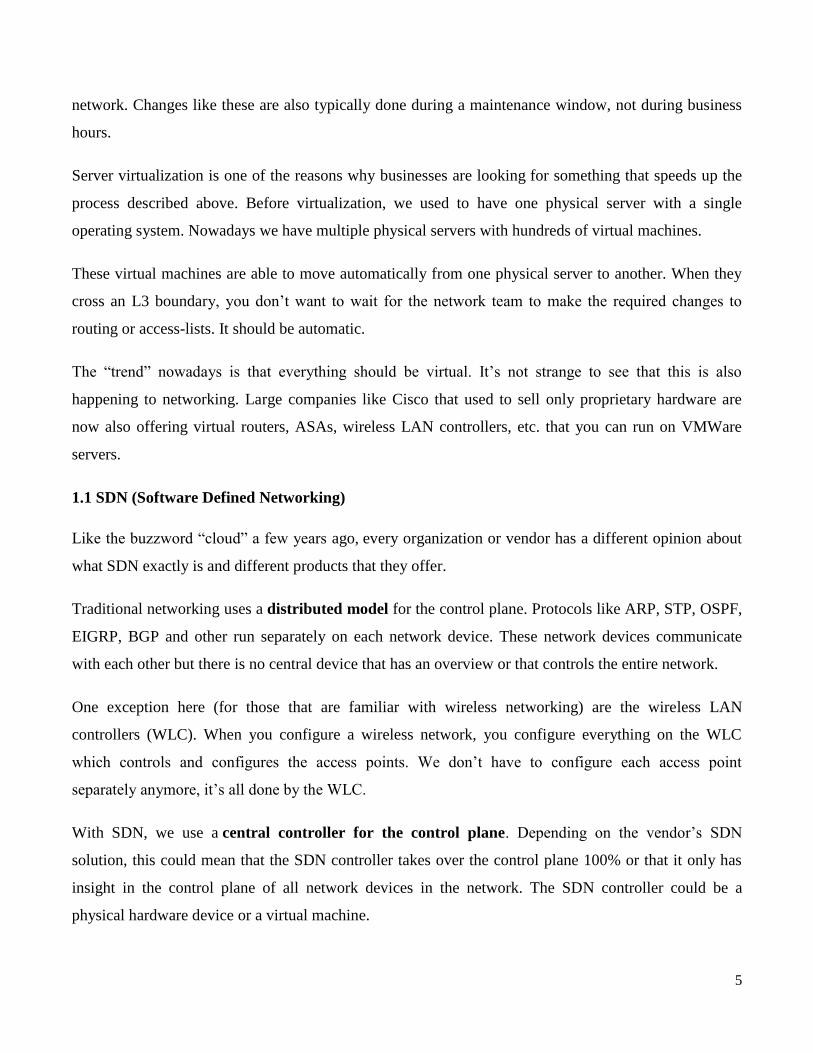
Here‘s an illustration to help you visualize this:
Figure 1.2 SDN Controller
Above you can see the SDN controller figure 1.2 which is responsible for the control plane. The
switches are now just ―dumb‖ devices that only have a data plane, no control plane. The SDN
controller is responsible for feeding the data plane of these switches with information from its control
plane.
There are some advantages and disadvantages of having a distributed vs a central control plane. One of
the advantages of having a central controller is that we can configure the entire network from a single
device. This controller has full access and insight of everything that is happening in our network.The
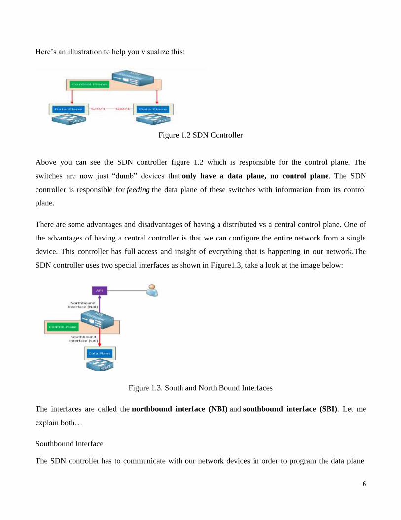
SDN controller uses two special interfaces as shown in Figure1.3, take a look at the image below:
Figure 1.3. South and North Bound Interfaces
The interfaces are called the northbound interface (NBI) and southbound interface (SBI). Let me
explain both…
Southbound Interface
The SDN controller has to communicate with our network devices in order to program the data plane.
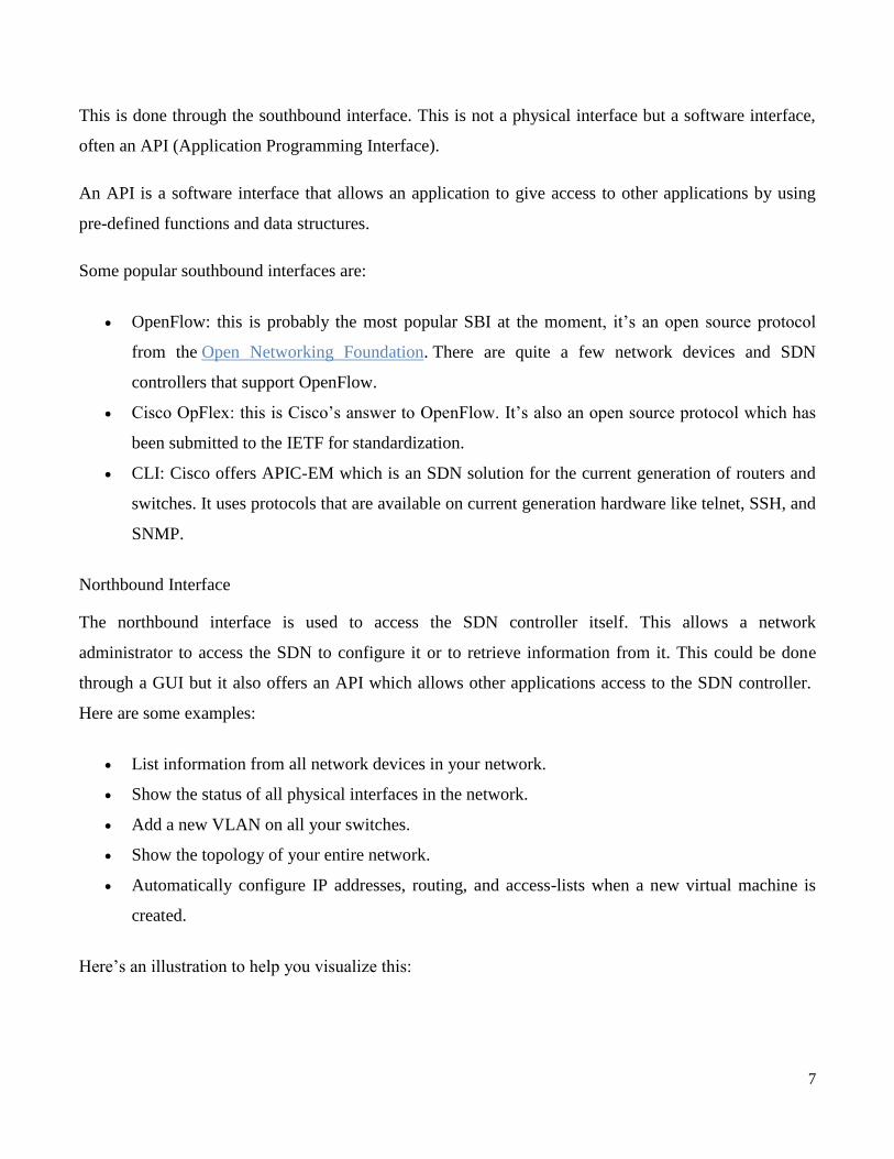
7
This is done through the southbound interface. This is not a physical interface but a software interface,
often an API (Application Programming Interface).
An API is a software interface that allows an application to give access to other applications by using
pre-defined functions and data structures.
Some popular southbound interfaces are:
OpenFlow: this is probably the most popular SBI at the moment, it‘s an open source protocol
from the Open Networking Foundation. There are quite a few network devices and SDN
controllers that support OpenFlow.
Cisco OpFlex: this is Cisco‘s answer to OpenFlow. It‘s also an open source protocol which has
been submitted to the IETF for standardization.
CLI: Cisco offers APIC-EM which is an SDN solution for the current generation of routers and
switches. It uses protocols that are available on current generation hardware like telnet, SSH, and
SNMP.
Northbound Interface
The northbound interface is used to access the SDN controller itself. This allows a network
administrator to access the SDN to configure it or to retrieve information from it. This could be done
through a GUI but it also offers an API which allows other applications access to the SDN controller.
Here are some examples:
List information from all network devices in your network.
Show the status of all physical interfaces in the network.
Add a new VLAN on all your switches.
Show the topology of your entire network.
Automatically configure IP addresses, routing, and access-lists when a new virtual machine is
created.
Here‘s an illustration to help you visualize this:

8
Figure 1.4. API in multiple applications
through the API, multiple applications are able to access the SDN controller as in figure 1.4.A user that
is using a GUI to retrieve information about the network from the SDN controller. Behind the scenes,
the GUI is using the API.
Scripts that are written in Java or Python can use the API to retrieve information from the SDN
controller or configure the network.
Other applications are able to access the SDN controller. Perhaps an application that
automatically configures the network once a new virtual machine is created on a VMware ESXi
server.
REST API
Let‘s take a closer look at what an API is. SDN controllers typically use a REST API
(Representational State Transfer).
The REST API uses HTTP messages to send and receive information between the SDN controller and
another application. It uses the same HTTP messages that you use when you browse a webpage on the
Internet or when you enter a contact form online:
HTTP GET: used when we want to retrieve information.
HTTP POST/PUT: used when we want to upload or update information.
It is similar browsing a webpage, only this time, you are not requesting a webpage or picture but a
particular object from the SDN controller, for example, a list with all VLANs in the network.

9
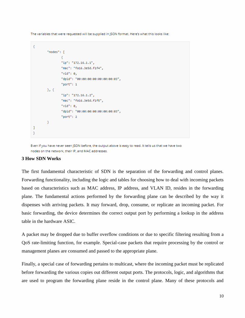
When the SDN controller receives the HTTP GET request in figure 1.5 it will reply with an HTTP GET
response in figure 1.6 with the information that was requested. This information is delivered in a
common data format. The two most used data formats are:
JSON (JavaScript Object Notation)
XML (eXtensible Markup Language)
Here‘s an example to help you visualize this:
Figure 1.5 Controller receives the HTTP GET request
Above we have a python script that is using HTTP GET to fetch the following URL through the
API:https://192.168.1.1:8443/sdn/v2.0/net/nodes.This URL will retrieve some of the variables that are
available, for example, information about all nodes (hosts) on the network.Once the API receives this, it
will respond with an HTTP GET response message:
Figure 1.6 Controller receives the HTTP GET response
10
3 How SDN Works
The first fundamental characteristic of SDN is the separation of the forwarding and control planes.
Forwarding functionality, including the logic and tables for choosing how to deal with incoming packets
based on characteristics such as MAC address, IP address, and VLAN ID, resides in the forwarding
plane. The fundamental actions performed by the forwarding plane can be described by the way it
dispenses with arriving packets. It may forward, drop, consume, or replicate an incoming packet. For
basic forwarding, the device determines the correct output port by performing a lookup in the address
table in the hardware ASIC.
A packet may be dropped due to buffer overflow conditions or due to specific filtering resulting from a
QoS rate-limiting function, for example. Special-case packets that require processing by the control or
management planes are consumed and passed to the appropriate plane.
Finally, a special case of forwarding pertains to multicast, where the incoming packet must be replicated
before forwarding the various copies out different output ports. The protocols, logic, and algorithms that
are used to program the forwarding plane reside in the control plane. Many of these protocols and

11
algorithms require global knowledge of the network. The control plane determines how the forwarding
tables and logic in the data plane should be programmed Software Defined Networks.
4 How SDN Works or configured
Since in a traditional network each device has its own control plane, the primary task of that control
plane is to run routing or switching protocols so that all the distributed forwarding tables on the devices
throughout the network stay synchronized. The most basic outcome of this synchronization is the
prevention of loops. Although these planes have traditionally been considered logically separate, they
co-reside in legacy Internet switches. In SDN, the control plane is moved off the switching device and
onto a centralized controller.
A Simple Device and Centralized Control Building on the idea of separation of forwarding and control
planes, the next characteristic is the simplification of devices, which are then controlled by a centralized
system running management and control software. Instead of hundreds of thousands of lines of
complicated control plane software running on the device and allowing the device to behave
autonomously, that software is removed from the device and placed in a centralized controller. This
software-based controller manages the network using higher-level policies. The controller then provides
primitive instructions to the simplified devices when appropriate in order to allow them to make fast
decisions about how to deal with incoming packets.
4.1 Network Automation and Virtualization
The centralized software-based controller in SDN provides an open interface on the controller to allow
for automated control of the network. In the context of Open SDN, the terms northbound and
southbound are often used to distinguish whether the interface is to the applications or to the devices.
The southbound API is the OpenFlow interface that the controller uses to program the network devices.
The controller offers a northbound API, allowing software applications to be plugged into the controller
and thereby allowing that software to provide the algorithms and protocols that can run the network
efficiently. These applications can quickly and dynamically make network changes as the need arises.
The northbound API of the controller is intended to provide an abstraction of the network devices and
topology. That is, the northbound API provides a generalized interface that allows the software above it
to operate without knowledge of the individual characteristics and idiosyncrasies of the network devices
12
themselves.
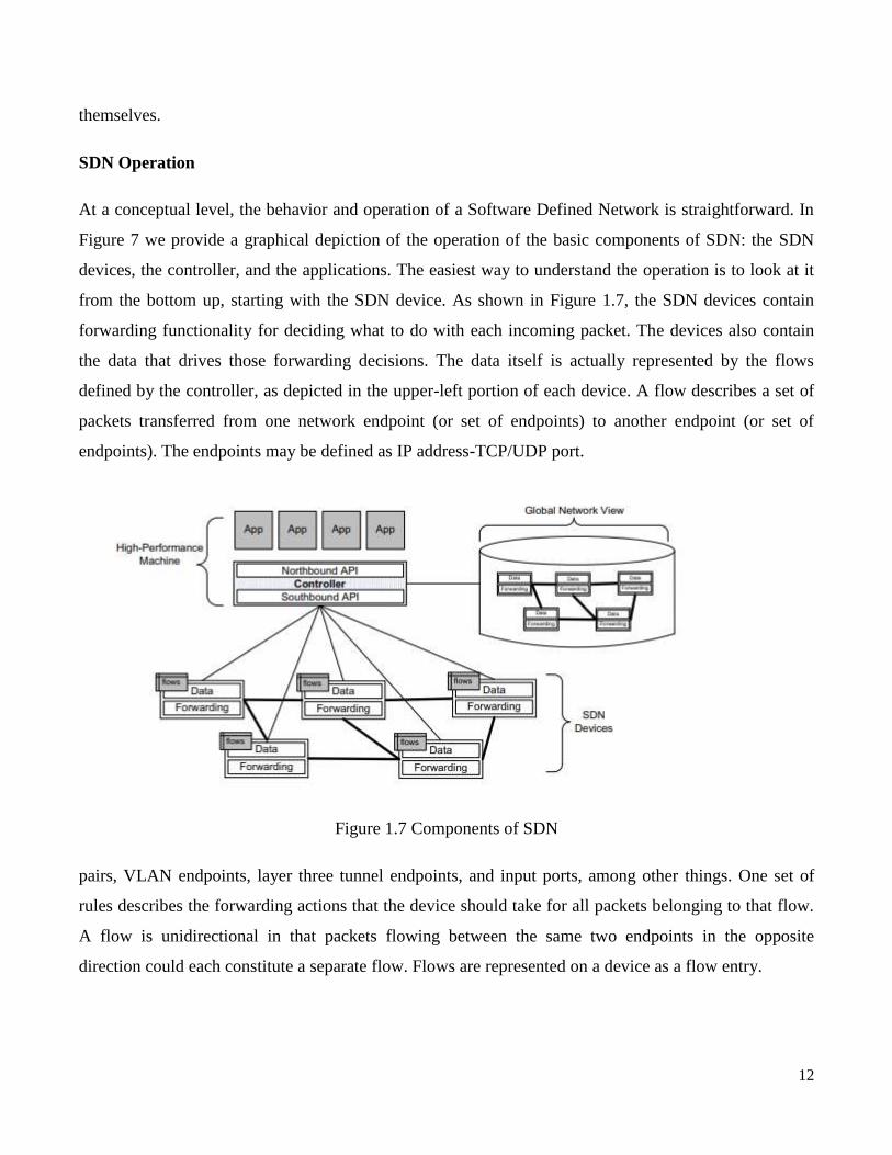
SDN Operation
At a conceptual level, the behavior and operation of a Software Defined Network is straightforward. In
Figure 7 we provide a graphical depiction of the operation of the basic components of SDN: the SDN
devices, the controller, and the applications. The easiest way to understand the operation is to look at it
from the bottom up, starting with the SDN device. As shown in Figure 1.7, the SDN devices contain
forwarding functionality for deciding what to do with each incoming packet. The devices also contain
the data that drives those forwarding decisions. The data itself is actually represented by the flows
defined by the controller, as depicted in the upper-left portion of each device. A flow describes a set of
packets transferred from one network endpoint (or set of endpoints) to another endpoint (or set of
endpoints). The endpoints may be defined as IP address-TCP/UDP port.
Figure 1.7 Components of SDN
pairs, VLAN endpoints, layer three tunnel endpoints, and input ports, among other things. One set of
rules describes the forwarding actions that the device should take for all packets belonging to that flow.
A flow is unidirectional in that packets flowing between the same two endpoints in the opposite
direction could each constitute a separate flow. Flows are represented on a device as a flow entry.
13
A flow table resides on the network device and consists of a series of flow entries and the actions to
perform when a packet matching that flow arrives at the device. When the SDN device receives a
packet, it consults its flow tables in search of a match. These flow tables had been constructed
previously when the controller downloaded appropriate flow rules to the device. If the SDN device finds
a match, it takes the appropriate configured action, which usually entails forwarding the packet. If it
does not find a match, the switch can either drop the packet or pass it to the controller, depending on the
version of OpenFlow and the configuration of the switch.
The controller allows the SDN application to define flows on devices and to help the application respond
to packets that are forwarded to the controller by the SDN devices. In Figure 7 we see on the right side
of the controller that it maintains a view of the entire network that it controls. This permits it to calculate
optimal forwarding solutions for the network in a deterministic, predictable manner. Since one controller
can control a large number of network devices, these calculations are normally performed on a high-
performance. Machine with an order-of-magnitude performance advantage over the CPU and memory
capacity than is typically afforded to the network devices themselves. For example, a controller might be
implemented on an eight-core, 2-GHz CPU versus the single-core, 1-GHz CPU that is more typical on a
switch.
SDN applications are built on top of the controller. These applications should not be confused with the
application layer defined in the seven-layer OSI model of computer networking. Since SDN applications
are really part of network layers two and three, this concept is orthogonal to that of applications in the
tight hierarchy of OSI protocol layers. The SDN application interfaces with the controller, using it to set
proactive flows on the devices and to receive packets that have been forwarded to the controller.
Proactive flows are established by the application; typically the application will set these flows when the
application starts up, and the flows will persist until some configuration change is made. This kind of
proactive flow is known as a static flow. Another kind of proactive flow is where the controller decides
to modify a flow based on the traffic load currently being driven through a network device.
In addition to flows defined proactively by the application, some flows are defined in response to a
packet forwarded to the controller. Upon receipt of incoming packets that have been forwarded to the
controller, the SDN application will instruct the controller as to how to respond to the packet and, if
appropriate, will establish new flows on the device in order to allow that device to respond locally the

14
next time it sees a packet belonging to that flow. Such flows are called reactive flows. In this way, it is
now possible to write software applications that implement forwarding, routing, overlay, multipath, and
access control functions, among others.
Figure 1.8 API with the Controller
An SDN device is composed of an API for communication with the controller, an abstraction layer, and
a packet-processing function. In the case of a virtual switch, this packet-processing function is packet
processing software, as shown in Figure 1.8. In the case of a physical switch, the packet-processing
function is embodied in the hardware for packet-processing logic, as shown in Figure 1.9.
Figure 1.9 packet-processing function
SDN hardware switch anatomy
The packet-processing logic consists of the mechanisms to take actions based on the results of
evaluating incoming packets and finding the highest-priority match. When a match is found, the
incoming packet is processed locally unless it is explicitly forwarded to the controller. When no match is
15
found, the packet may be copied to the controller for further processing. This process is also referred to
as the controller consuming the packet.
In the case of a software switch, these same functions are mirrored by software. Since the case of the
software switch is somewhat simpler than the hardware switch .the actual packet-forwarding logic
migrated into hardware for switches that needed to process packets arriving at ever-increasing line rates.
More recently, a role has reemerged in the data center for the pure software switch. Such a switch is
implemented as a software application usually running in conjunction with a hypervisor in a data center
rack. Like a VM, the virtual switch can be instantiated or moved under software control. It normally
serves as a virtual switch and works collectively with a set of other such virtual switches to constitute a
virtual network.
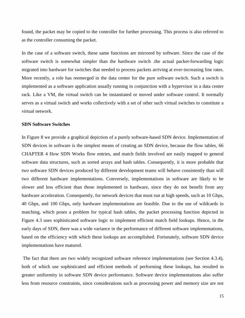
SDN Software Switches
In Figure 8 we provide a graphical depiction of a purely software-based SDN device. Implementation of
SDN devices in software is the simplest means of creating an SDN device, because the flow tables, 66
CHAPTER 4 How SDN Works flow entries, and match fields involved are easily mapped to general
software data structures, such as sorted arrays and hash tables. Consequently, it is more probable that
two software SDN devices produced by different development teams will behave consistently than will
two different hardware implementations. Conversely, implementations in software are likely to be
slower and less efficient than those implemented in hardware, since they do not benefit from any
hardware acceleration. Consequently, for network devices that must run at high speeds, such as 10 Gbps,
40 Gbps, and 100 Gbps, only hardware implementations are feasible. Due to the use of wildcards in
matching, which poses a problem for typical hash tables, the packet processing function depicted in
Figure 4.3 uses sophisticated software logic to implement efficient match field lookups. Hence, in the
early days of SDN, there was a wide variance in the performance of different software implementations,
based on the efficiency with which these lookups are accomplished. Fortunately, software SDN device
implementations have matured.
The fact that there are two widely recognized software reference implementations (see Section 4.3.4),
both of which use sophisticated and efficient methods of performing these lookups, has resulted in
greater uniformity in software SDN device performance. Software device implementations also suffer
less from resource constraints, since considerations such as processing power and memory size are not

16
an issue in typical implementations. Thus, whereas a hardware SDN device implementation will support
only a comparatively limited number of flow entries, the ceiling on the number of flow entries on a
software device may be orders of magnitude larger. As software device implementations have more
flexibility to implement more complex actions, we expect to see a richer set of actions available on
software SDN device implementations than on the hardware SDN devices that we examine in the next
section. Software SDN device implementations are most often found in software-based network devices,
such as the hypervisors of a virtualization system. These hypervisors often incorporate a software switch
implementation that connects the various virtual machines to the virtual network. The virtual switch
working with a hypervisor is a natural fit for SDN. In fact, the whole virtualization system is often
controlled by a centralized management system, which also meshes well with the centralized controller
aspect of the SDN paradigm.
Hardware SDN Devices Hardware implementations of SDN devices hold the promise of operating
much faster than their software counterparts and, thus, are more applicable to performance-sensitive
environments, such as in data centers and network cores. To understand how SDN objects such as flow
tables and flow entries can be translated into hardware, her we briefly review some of the hardware
components of today‘s networking devices.
Currently, network devices utilize specialized hardware designed to facilitate the inspection of incoming
packets and the subsequent decisions that follow based on the packet-matching operation.This hardware
includes the layer two and layer three forwarding tables, usually implemented using content-addressable
memories (CAMs) and ternary content-addressable memories (TCAMs).
The layer three forwarding table is used for making IP-level routing decisions. This is the fundamental
operation of a router. It matches the destination IP address against entries in the table takes the
appropriate routing action (e.g., forwards the packet out interface B3). The layer two forwarding table is
used for making MAC-level forwarding decisions. This is the fundamental operation of a switch. It
matches the destination MAC address against entries in the table and, based on the match, takes the
appropriate forwarding action (e.g., forwards out interface 15).
The layer two forwarding table is typically implemented using regular CAM or hardware-based hashing.
These kinds of associative memories are used when there are precise indices, such as a 48-bit MAC
address. TCAMs, however, are associated with more complex matching functions. TCAMs are used in
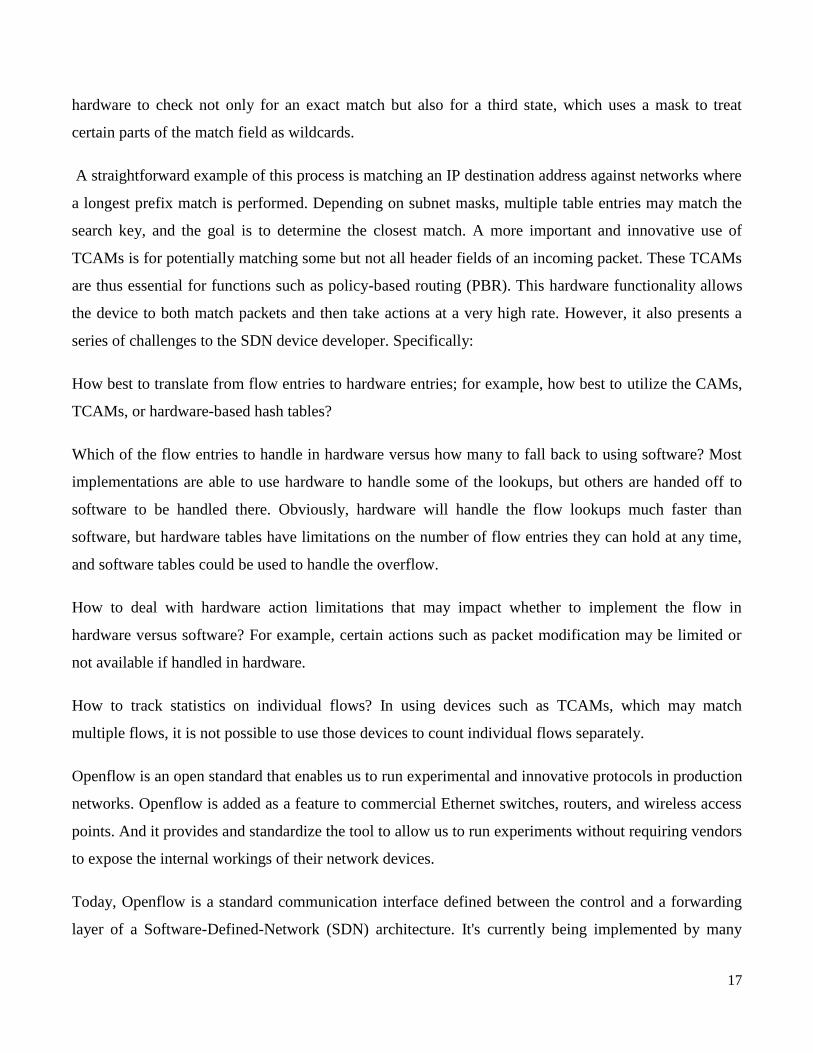
17
hardware to check not only for an exact match but also for a third state, which uses a mask to treat
certain parts of the match field as wildcards.
A straightforward example of this process is matching an IP destination address against networks where
a longest prefix match is performed. Depending on subnet masks, multiple table entries may match the
search key, and the goal is to determine the closest match. A more important and innovative use of
TCAMs is for potentially matching some but not all header fields of an incoming packet. These TCAMs
are thus essential for functions such as policy-based routing (PBR). This hardware functionality allows
the device to both match packets and then take actions at a very high rate. However, it also presents a
series of challenges to the SDN device developer. Specifically:
How best to translate from flow entries to hardware entries; for example, how best to utilize the CAMs,
TCAMs, or hardware-based hash tables?
Which of the flow entries to handle in hardware versus how many to fall back to using software? Most
implementations are able to use hardware to handle some of the lookups, but others are handed off to
software to be handled there. Obviously, hardware will handle the flow lookups much faster than
software, but hardware tables have limitations on the number of flow entries they can hold at any time,
and software tables could be used to handle the overflow.
How to deal with hardware action limitations that may impact whether to implement the flow in
hardware versus software? For example, certain actions such as packet modification may be limited or
not available if handled in hardware.
How to track statistics on individual flows? In using devices such as TCAMs, which may match
multiple flows, it is not possible to use those devices to count individual flows separately.
Openflow is an open standard that enables us to run experimental and innovative protocols in production
networks. Openflow is added as a feature to commercial Ethernet switches, routers, and wireless access
points. And it provides and standardize the tool to allow us to run experiments without requiring vendors
to expose the internal workings of their network devices.
Today, Openflow is a standard communication interface defined between the control and a forwarding
layer of a Software-Defined-Network (SDN) architecture. It's currently being implemented by many
18
vendors with Openflow enabled switch, now commercially available. Openflow became common in
2010. Its concept was first published in an ACM SIGCOMM 2008 paper, and its version 1.1 was
released in early 2011 as a protocol for programming forwarding plane of a network switch or router.
Based on it, Open SDN was proposed in 2011.
All the views of SDN includes SDN via API model, used by Cisco, which allows developers to
manipulate network devices using an extended API. Also, VMware use SDN might overlays. However,
for this lesson we refer to only one view: the Open SDN. In late 2012, the concept on Network Function
Virtualization, NFV, was defined, which is not our replacement for SDN, but rather both SDN and NFV
complement each other.
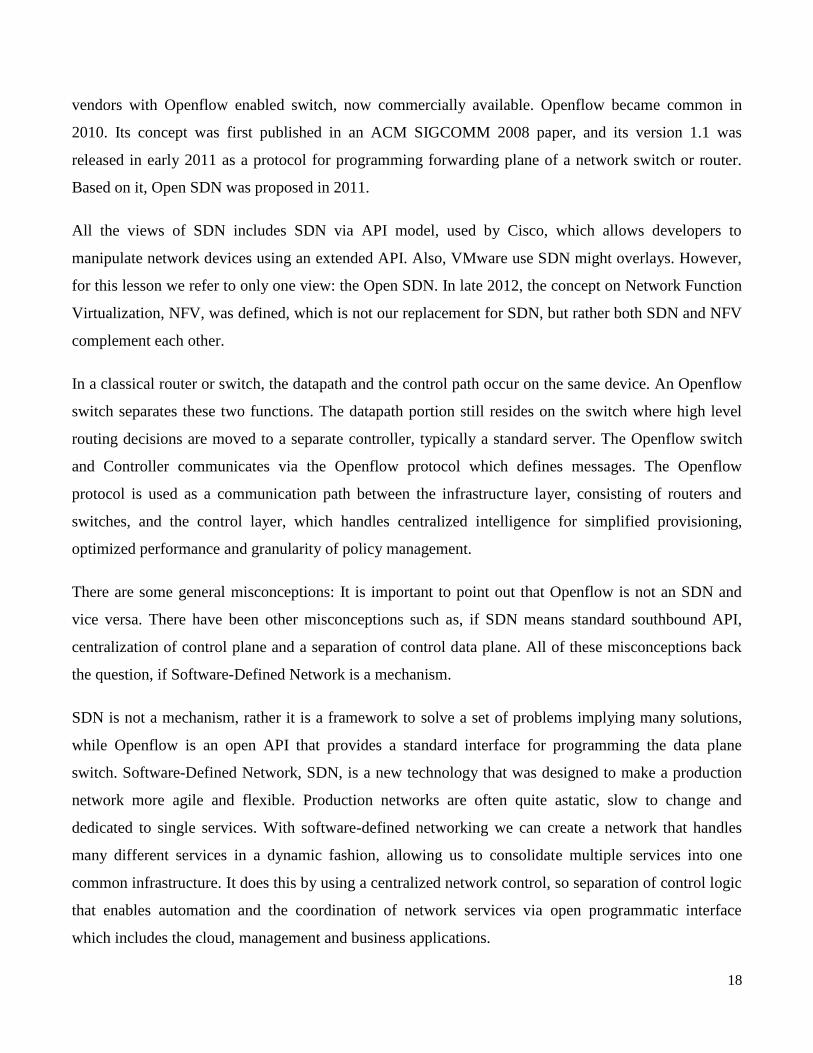
In a classical router or switch, the datapath and the control path occur on the same device. An Openflow
switch separates these two functions. The datapath portion still resides on the switch where high level
routing decisions are moved to a separate controller, typically a standard server. The Openflow switch
and Controller communicates via the Openflow protocol which defines messages. The Openflow
protocol is used as a communication path between the infrastructure layer, consisting of routers and
switches, and the control layer, which handles centralized intelligence for simplified provisioning,
optimized performance and granularity of policy management.
There are some general misconceptions: It is important to point out that Openflow is not an SDN and
vice versa. There have been other misconceptions such as, if SDN means standard southbound API,
centralization of control plane and a separation of control data plane. All of these misconceptions back
the question, if Software-Defined Network is a mechanism.
SDN is not a mechanism, rather it is a framework to solve a set of problems implying many solutions,
while Openflow is an open API that provides a standard interface for programming the data plane
switch. Software-Defined Network, SDN, is a new technology that was designed to make a production
network more agile and flexible. Production networks are often quite astatic, slow to change and
dedicated to single services. With software-defined networking we can create a network that handles
many different services in a dynamic fashion, allowing us to consolidate multiple services into one
common infrastructure. It does this by using a centralized network control, so separation of control logic
that enables automation and the coordination of network services via open programmatic interface
which includes the cloud, management and business applications.

19
The main advantages of SDN include efficiency, by optimizing existing applications, services and
infrastructure, scalability and innovation. Now, developers can create and deliver new types of
application, and services and new business models.
The need of SDN is driven by several factors: visualization, that remove the need to know where
network resources are physically located, resource cost, organization and so on. Orchestration that is the
need to control and manage thousands of devices with one command can be achieved. Programmability,
the ease of changing network behaviors without horrible upgrades.
Dynamic scaling that should be able to change size and quantity. Automation that requires minimal
manual involvement in operation as cushion, such as troubleshooting and resource provisioning.
Visibility, that allows resource monitoring on network connectivity. Performance, that is due to traffic
engineering, capacity optimization, load balancing and the high utilization.
Multi-tenancy, that allows administration access of address, topology, routing, security and service
integration of load of balancer, intrusion detection system and firewalls.
Network Function Virtualization is a consolidation of different network functions within a virtual server
rather than deploying different hardware for different network function. As such, it decouples functions
like a firewall or encryption from dedicated hardware and moves the function to virtual servers.
The term NFV refer to the strategy of virtualizing network function, moving from separate pieces of
hardware to software running on virtual servers using standard hardware. There are four major
innovations of Network Function Virtualization, which includes standard API between modules.
Network functions are implemented in virtual machines. Network function modules that enhance easy
programmability and a software implementation of network.
5 A brief history of SDN
SDN is about separating the control plane and the forwarding plane, enabling network control to become
programmable and centralized and the underlying network elements abstracted from the applications and
services.In the early days of SDN, it was associated with OpenFlow, which is a protocol that can be used
to realize L2/L3 switching, firewalls, and many more by leveraging a generic table-based pipeline.
Network controllers can administer and configure the switches‘ forwarding plane, as long as the vendor
20
ecosystem implements and exposes the OpenFlow APIs. That way, based on the need or use case, the
forwarding plane could be (re)configured dynamically through remote and centralized administration.
Internet of Things (IoT) is a catalyst offering many possibilities and setting the bar for a high degree of
networking automation (else operations will not scale).Furthermore, as data has become a currency—
and as data analytics, machine learning and artificial intelligence (AI/ML) are on the rise—the network
needs to be efficient both from a capacity and a reliability perspective.
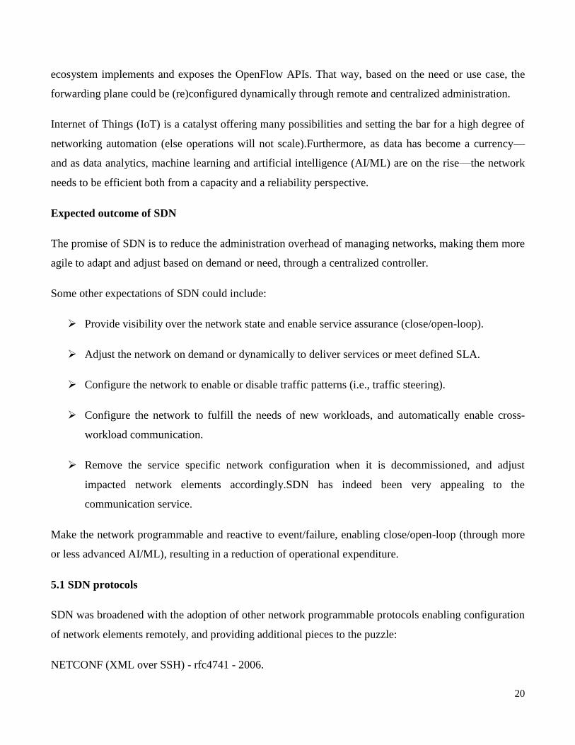
Expected outcome of SDN
The promise of SDN is to reduce the administration overhead of managing networks, making them more
agile to adapt and adjust based on demand or need, through a centralized controller.
Some other expectations of SDN could include:
Provide visibility over the network state and enable service assurance (close/open-loop).
Adjust the network on demand or dynamically to deliver services or meet defined SLA.
Configure the network to enable or disable traffic patterns (i.e., traffic steering).
Configure the network to fulfill the needs of new workloads, and automatically enable cross-
workload communication.
Remove the service specific network configuration when it is decommissioned, and adjust
impacted network elements accordingly.SDN has indeed been very appealing to the
communication service.
Make the network programmable and reactive to event/failure, enabling close/open-loop (through more
or less advanced AI/ML), resulting in a reduction of operational expenditure.
5.1 SDN protocols
SDN was broadened with the adoption of other network programmable protocols enabling configuration
of network elements remotely, and providing additional pieces to the puzzle:
NETCONF (XML over SSH) - rfc4741 - 2006.
21
RESTCONF (XML/JSON over HTTP - REST) - rfc8040 - 2017.
gMNI/gNOI (gRPC over HTTP2) - 2018.
This is a non-exhaustive list, but these are the ones I see really driving momentum.NETCONF brought
many things enabling remote network configuration; to name a few:
Client-server connection-oriented session with SSH.
Democratization of YANG as a data modeling language (displacing the vendor defined XML
schema-based configuration definition).
Remote Procedure Call (RPC) based operations.
Standardization of RPCs to query and configure a network element‘s configuration/state.Notion
of state and datastore: configuration and operation datastore respectfully tracking the declarative
requested state, versus the actual runtime state.
Network monitoring with a notification framework, subscription-based.
RESTCONF uses HTTP methods to implement the equivalent of NETCONF operations, enabling basic
CRUD operations on a hierarchy of conceptual resources. […] The HTTP POST, PUT, PATCH, and
DELETE methods are used to edit data resources represented by YANG data models. These basic edit
operations allow the running configuration to be altered by a RESTCONF client", as defined in the
RFC8040.
It basically made the interaction with network elements even more trivial for developers.gRPC Network
Management Interface and gRPC Network Operation Interface brought a new paradigm for network
element monitoring with bulk data collection through streaming telemetry. It also provides a way more
effective underlying protocol for RPC, leveraging gRPC / HTTP2.
Another important thing to note is these three protocols heavily rely on YANG as a data modelling
language (rfc6020 – 2010), which opened the door to model-driven programmability.This enabled the
open source networking communities to standardize network element configuration data model by
providing a vendor-neutral solution. For a telco striving to abstract its underlying network infrastructure,
and reaching a high level of interoperability, this has become very attractive.
22
The most adopted and mature models are the ones from OpenConfig, mostly for routers, and Open
ROADM for optical elements. But not all the vendors support them, and there is a lot of mapping to
perform between the vendor model and the OpenConfig model when trying to abstract the whole
network with them.
5.2 How SDN has evolved
Initially, there was a proliferation of SDN controllers, and most of them really focused on OpenFlow,
and its related Open vSwitch (OVS). But some of them took a different approach, and provided more of
a platform where one could turn on the protocols they would care about (ONOS, OpenDaylight).
What really made SDN a thing is its adoption in OpenStack through Open Virtual Network (OVN)
around 2016. OpenStack, created in 2010, really has proven the capabilities that SDN has to offer, and at
the same time, made open source networking a real thing (it took a few years for this to happen though).
It also streamlined Network Function Virtualization (NFV), making itself the default platform for the
telecommunication industry to run the vendor provided network functions.
Since then, a lot has happened in the open source community (and in the various standard bodies). To
name a few, The Linux Foundation Networking (LFN) and the Open Networking Foundation (ONF)
helped to bring together vendors, operators and enterprises. They both host a number of projects
important to momentum and adoption (ONOS, P4, ONAP, OpenDaylight, Open vSwitch to name a
few).
5.3 The virtualization of infrastructure
As software evolved and more systems became virtualized, telco saw the opportunity to have their
network functions virtualized. By decoupling software from hardware, it enables the consumption of
cost-effective commodity hardware, and optimization of the overall infrastructure.
For this to happen, telco had to arm wrestle again with network equipment vendors so they would make
their network functions run outside of their custom build and dedicated hardware.
Also, making network functions virtual created a whole new domain of expertise, the infrastructure on
which they run: Network Function Virtualization infrastructure (NVFi). As you virtualize, you add a
23
layer of abstraction that has a cost in terms of networking, compute and memory— the impact on the
end user is not acceptable.
The LFN and its community created projects aimed at integrating various software stacks and enabling
the validation of vendor-provided Virtual Network Function (VNF) on standardized infrastructure:
OPNFV. Cloud iNfrastructure Telco Task Force (CNTT) is another telco-centric open source initiative
that is striving for similar goals.
Are vendor-provided VNF really successful, though? They still require an important amount of
integration and customization of the underlying infrastructure to get the expected performance, defeating
the initial promise of having a shared infrastructure.
In parallel, standard bodies have been standardizing the interfaces to control and manage these network
functions and their related OSS/BSS stack (ESTI, TMForum, GSMA, etc.), but they are mostly
geographically adopted. Whether you‘re in EMEA, APAC or NA, not every telco wants the same
standard, which makes things even harder for the vendor ecosystem.
The data plane consists of physical servers where customers' Amazon EC2 instances run. The control
plane consists of a number of services that interact with the data plane, performing functions such as
these: ... Receiving metering data, logs, and metrics emitted by the servers.
6 IEFT forces
Addressable Entity (AE):
A physical device that is directly addressable given some interconnect technology. For example, on IP
networks, it is a device that can be reached using an IP address; and on a switch fabric, it is a device that
can be reached using a switch fabric port number.
Control Element (CE):
A logical entity that implements the ForCES protocol and uses it to instruct one or more FEs on how to
process packets. CEs handle functionality such as the execution of control and signaling protocols.
CE Manager (CEM):
24
A logical entity responsible for generic CE management tasks. It is particularly used during the pre-
association phase to determine with which FE(s) a CE should communicate. This process is called FE
discovery and may involve the CE manager learning the capabilities of available FEs.
Data Path: A conceptual path taken by packets within the forwarding plane inside an FE.
Forwarding Element (FE): A logical entity that implements the ForCES protocol. FEs use the
underlying hardware to provide per-packet processing and handling as directed/controlled by one or
more CEs via the ForCES protocol.
FE Model:
A model that describes the logical processing functions of an FE. The FE model is defined using Logical
Function Blocks (LFBs).
FE Manager (FEM):
A logical entity responsible for generic FE management tasks. It is used during the pre-association
phase to determine with which CE(s) an FE should communicate. This process is called CE discovery
and may involve the FE manager learning the capabilities of available CEs. An FE manager may use
anything from a static configuration to a pre-association phase protocol (see below) to determine
which CE(s) to use. Being a logical entity, an FE manager might be physically combined with any
of the other logical entities such as FEs.
Network Element (NE):
An entity composed of one or more CEs and one or more FEs. To entities outside an NE, the NE
represents a single point of management. Similarly, an NE usually hides its internal organization from
external entities.
High Touch Capability:
This term will be used to apply to the capabilities found in some forwarders to take action on the
contents or headers of a packet based on content other than what is found in the IP header. Examples
of these capabilities include quality of service (QoS) policies,virtual private networks, firewall, and L7
content recognition.
25
LFB (Logical Function Block):
The basic building block that is operated on by the ForCES protocol.The LFB is a well-defined,
logically separable functional block that resides in an FE and is controlled by the CE via the ForCES
protocol.The LFB may reside at the FE's data path and process packets or may be purely an FE control
or configuration entity that is operated on by the CE. Note that the LFB is a functionally accurate
abstraction of the FE's processing capabilities, but not a hardware-accurate representation of the FE
implementation.
FE Topology:
A representation of how the multiple FEs within a single NE are interconnected. Sometimes this is
called inter-FE topology, to be distinguished from intra-FE topology (i.e., LFB topology).
LFB Class and LFB Instance:
LFBs are categorized by LFB classes. An LFB instance represents an LFB class (or type) existence.
There may be multiple instances of the same LFB class (or type) in an FE. An LFB class is
represented by an LFB class ID, and an LFB instance is represented by an LFB instance ID. As a
result, an LFB class ID associated with an LFB instance ID uniquely specifies an LFB existence.
LFB Meta Data:
Meta data is used to communicate per-packet state from one LFB to another, but is not sent across the
network. The FE model defines how such meta data is identified, produced, and consumed by the
LFBs. It defines the functionality but not how meta data is encoded within an implementation.
7 Active networks
Network and its variance meets the scalability demands of a data center network, and it is also cost-
effective. Those two things are good. But however, the network is dependent on the fact that you have
intelligent routing decision. Because there're different communication paths between any two end
points, take different communication routes. So intelligent routing is a key to ensuring performance
between the end hosts. Now if you statically decide the routing between any two servers that would
result in congestion and hotspots in the network. Even though we've got redundant paths available in the

26
class network, you might still end up with congestion and hotspots. So what we really want is the
routing to be not static, but we want it to be dynamic, and this calls for an active network where the
routing decisions are being taken dynamically.
It turns out this requirement for wanting the network routing to be active is not new. Let's talk about
how routing works in the Internet today. Your packet consists of a destination and a payload, and what
happens in a traditional routing network is that routing decisions in the internet are static, and it is
decided by look-up-tables in the routers that are periodically updated. So if you look at this structure
here, this is the source and this is destination, let say, and there are intermediate routers that a particular
packet may take in order to go from source to destination.
What each one of these intermediate states in the packet traversal is doing, is basically doing a lookup in
the look-up-table, which is getting updated periodically. So when a packet comes in, what router is
going to do is, it's going to see the lookup-table and decide what the next hop to send the packet to is.
That's all that every one of these routers are doing. So packet arrives, you look up the lookup table, find
the next hop for the destination, given the destination field in the table entry, and then you route it. This
is static routing, so the next hop is static. Now, what does it mean to make it active? Well active means
that this routers are not looking up any tables, but they're making dynamic decisions. How can they take
the dynamic decision? This is a vision that was proposed by Tennenhouse and Weatherall in the mid
90s, and it is called Active Network.
Now if you look at the packet, it consists of three parts. There is, of course, the destination, where the
packet has to reach, the payload, but there's a new thing, which is the code. What happens is that when a
packet comes in, this router is going to execute this code and make a dynamic decision where to send
that packet, and this code has to be carried in every packet, and it can be executed in the routers between
source and destination.
That way, routers can make dynamic routing decision. So that's the idea behind active network.
Unfortunately, this was proposed in the mid 90s, but this was way ahead of its time. The principal
shortcomings of the active network vision versus the reality is the fact that the lots of vulnerabilities that
you have to be worried about. The first of all, there's the protection threats that a packet is carrying code,
and it is going to execute in a router,
27
The second is resource management threats, meaning that if a package that comes in has code that is
going to get executed in the router, what kind of resources is it going to use as a router, and how is it
affecting other flows through the network fabric? So that becomes another important issue. Perhaps a
very important issue is the fact that the router vendors are loath to opening up the network, and letting
arbitrary code to run on the routers.
Cisco is a router king, it cannot tell router, "Open up your network so that I can execute coordinate
orders" So that's not something that is going to happen really easily. Software routing, meaning that a
packet comes in, you're not just looking up a table, and then dispatching the packet immediately where
it's executing code, which is executing in software, that is going to be much slower than meeting the line
speeds at which hardware routers work.
In Cloud Computing. the service providers want to provide dynamic routing decisions to ensure
performance isolation for the network traffic when you have multi-tenancy in the network. But now
there are chipsets available for assembling your own router, so it's much easier than, I don't mean that
everybody like you and me, but technology giants like Cisco, or Facebook, if they want to build their
own router, no problem, they can build it together. Chipsets are available, makes it easy for building
your own router, skirting the need for buy in from router vendors. So these are all the factors that make
the idea of active routing once again, feasible in today's world.
A data center is a facility that centralizes an organization's IT operations and equipment, as well as
where it stores, manages, and disseminates its data. Data centers house a network's most critical
systems and are vital to the continuity of daily operations.
The term ―data center‖ can be interpreted in a few different ways. First, an organization can run an
in- house data center maintained by trained IT employees whose job it is to keep the system up and
running. Second, it can refer to an offsite storage center that consists of servers and other equipment
needed to keep the stored data accessible both virtually and physically.
Pros: Data centers come with a number of pros. Organizations able to have an in-house data storage
center are far less reliant on maintaining an Internet connection. Data will be accessible as long as
28
the local network remains stable. Remote storage has its advantages as well. If the organization‘s
location is compromised via fire, break-in, flooding, etc., the data will remain untouched and
unharmed at its remote location.
Cons: Having all or most of our data stored in one location makes it more easily accessible to those
we don‘t want having access, both virtually and physically. Depending on our organization‘s
budget, it could prove too expensive to maintain an organization-owned and operated data center. A
data center is ideal for companies that need a customized, dedicated system that gives them full
control over their data and equipment. Since only the company will be using the infrastructure's
poor, a data center is also more suitable for organizations that run many different types of
applications and complex workloads. A data center, however, has limited capacity -- once we build
a data center, we will not be able to change the amount of storage and workload it can withstand
without purchasing and installing more equipment.
On the other hand, a cloud system is scalable to our business needs. It has potentially unlimited
capacity, based on our vendor's offerings and service plans. One disadvantage of the cloud is that
we will not have as much control as we would a data center, since a third party is managing the
system. Furthermore, unless we have a private cloud within the company network, we will be
sharing resources with other cloud users in our provider's public cloud.
Difference between a data center and cloud computing
The main difference between a cloud and a data center is that a cloud is an off-premise form of
computing that stores data on the Internet, whereas a data center refers to on-premise hardware
that stores data within an organization's local network. Where is data stored in the cloud?
Cloud storage is a model of data storage in which the digital data is stored in logical pools, the
physical storage spans multiple servers (and often locations), and the physical environment is
typically owned and managed by a hosting company.
Data center hosting is the process of deploying and hosting a data center on a third-party or
external service provider's infrastructure. It enables the use of the same services, features and
capabilities of a data center but from a hosted platform external to the on-premises data center or
IT infrastructure.

29
Key Features of Cloud Data Center
N number of applications hosted in different location are residing on the same cloud
Primary and secondary(back up) database reside on the same cloud
As secondary database resides on the same cloud so even if primary database goes down, there
would be no loss of data.
At any point of time new applications can be added on cloud, since it is easily scalable.
Stores data on the Internet
Requires no special equipment and knowledge
Homogeneous hardware environment
Simple workloads
Single standard software architecture
Uses standardized management tools
The cost of running cloud data center is much low
o Cloud data center requires 6 percent for operation, 20 percent for poour
distribution and cooling. Almost 48 percent is spent on maintenance
Cloud data center is an external form of computing so it may be less secure.
o If cloud resides on different locations proper security steps have to be
implemented. However, there are wide range of ways available to secure data on
cloud.
Self-service, pay per use
Automated recovery in case of failure
Renting is on basis of logical usage
30
Platform Independent
Easily scalable on demand
With passing years the transaction of data across the network is going to boom and thereby the need
of storage is going to increase rapidly. When thinking about management of such rapidly growing
data chain, data center will soon lose its dominant status. The reason behind this is scalability and
the operating cost of data center.
Traditional data centers are heavily bound by physical limitations, making expansion a major
concern. Even if data center manages the explosion of data still no company would afford to buy it.
Due to energy cost involved in running and cooling the data center, life of traditional data center is
soon to end. And as a result, Cloud data center would be replacing traditional data center. Cloud
data center can operate with bulk of data being generated. Due to its pay-as-we-use model,
companies find it more reliable to work with. Minimal cost is required for operating cloud which
again wins over traditional data center. The results clearly state that Cloud data center offers
immense potential in areas of scale, cost, and maintenance.
Energy Efficiency in Data Center
Cloud computing is an internet based computing which provides metering based services to
consumers. It means accessing data from a centralized pool of compute resources that can be ordered
and consumed on demand. It also provides computing resources through virtualization over
internet.
Data center is the most prominent in cloud computing which contains collection of servers on
which Business information is stored and applications run. Data center which includes servers,
cables, air conditioner, network etc.. consumes more power and releases huge amount of Carbon-di-
oxide (CO2) to the environment. One of the most important challenge faced in cloud computing is
the optimization of Energy Utilization. Hence the concept of green cloud computing came into
existence.
There are multiple techniques and algorithms used to minimize the energy consumption in cloud.
Techniques include:
31
1. Dynamic Voltage and Frequency Scaling (DVFS)
2. Virtual Machine (VM)
3. Migration and VM Consolidation
Algorithms are:
1. Maximum Bin Packing
2. Poour Expand Min-Max and Minimization Migrations
3. Highest Potential growth
Data centers
Data centers are therefore providing scalable computing resources for reliable computing, for massive
internet scale services, that's what we're all used to. These data centers tend to be located in
geographically dispersed areas. Often, they maybe in remote areas for optimizing on conditions like
energy consumption and making sure that we get economic power.
Those are some of the issues in the location of data centers. If you look inside a data center, the network
is one of the main components of the computational resources in a data center and these networking
fabric connects all of the servers that are inside a data center, and it also provides connectivity to the
clients that are out here via the internet. So that's the role of the routing fabric, both for internal
communication among these servers inside the data center, as well as for going out on the internet
and connecting to the clients that could be anywhere in the world.
If you look at the considerations for the design of data center networks, the first thing that should jump
at you is the fact that we've got hundreds of thousands of servers that are going to be located inside a
data center today and if you take a single app, for example Gmail, it may be running on thousands of
servers simultaneously, and these servers have to communicate with one another very quickly, very
rapidly, so latency is important, and also throughput is equally important and these data centers are
multi-tenancy.
What does that mean? Well, it means that simultaneously, there could be multiple applications that can
32
be coexisting on the computation resources of the server. The expectation for applications is that they'll
have good performance so that the network capacity is uniform for supporting all the applications that
maybe running simultaneously. Now if you think about it, if you have any two servers and they're
communicating with each other, the communication is bound by only the network interface
between them, that's the expectation. When you're running an application on a local area network and
you're connecting it through a local area network, you're bound only by the interface speed that is
connecting these servers. But now in a data center, we've got a routing fabric and so these
servers actually go through the routing fabric in order to talk to one another, but yet you want layer 2
semantics. Layer 2, is the link layer, so like the Ethernet. When you're connected on a local area
network, your expectation is that at link speed you can communicate with one another. But now you're
going through a network fabric in order to communicate with one another, but yet you expect that all the
individual applications will have layer 2 semantics for communication.
That is a key property that you want to have in the network fabric. What that also means is that despite
the fact that this network fabric is being shared by multiple servers, every one of these applications
is thinking that they're running on a local area network from the point of view of the performance. That's
one of the key properties that you want to build into the routing fabric. There's also a need
for performance isolation for the applications, meaning that the traffic of one server should not interfere
with the traffic of another server. So these are some of the properties or considerations that you have in
building data center networks. So if you look at the scale of the data center networks, it's huge, and now
it begs the question, how do you build these data center networks? Do you use commodity switches, or
do you use special switching fabric? Meaning, if you want to provide this uniform capacity for all the
applications, perhaps you want a special switching fabric to connect all these servers together but that
won't be cost effective given the scale of the data centers that you're talking about and therefore it
is attracted to think about using commodity switches.
What I mean by commodity switches is, they are routers and the Ethernet switches that you're all used
to and that is in the core of the wide area networks today. So those are the switches are commodity and
therefore it is cheap, and therefore you can use that to build large-scale network fabric. So that's the
attraction for building data center networks using commodity switching elements. But if you look at it
from the point of view of the design is the network topology to be like a crossbar interconnection
network. Because if you have a crossbar interconnection network, then you can connect any element to

33
any other element and all of them can work simultaneously with constant latency for
communication, and there is no interference between them, no congestion in the network.
network topology should look like a crossbar, but it should not cost like a crossbar. So that becomes the
important design consideration in building data center networks, and it turns out that if you go back in
time, in the early days of telephony, they had the same dilemma while building telephone
switches. There also, you have a large number of subscribers who want to communicate with one
another and you want a crossbar-like network so that you can connect any subscriber to any other
subscriber, and they're not competing with each other, you can have simultaneous connection between
all of them. This led Charles Clos to come up with a network called Clos network, which is a scalable
interconnection network for meeting the bandwidth requirements for the end devices using commodity
switches, this is the key. So instead of building specialist switching fabric, Charles Clos was able to
build using commodity switches network for connecting subscribers in a telephone switching
network, It turns out that data center networks are taking the same approach in today's world. So in
other words, something that was good in the '50s for telephony has become really good for building data
center networks today.
There are several features of the Clos network resources for building a true crossbar because there are
, capital N elements here, so capital N elements here, that wants to talk to capital N elements at the same
time, and so long as the pairs of communicating entities are distinct from one another, all these
conversations should go on in parallel simultaneously without interfering with one another, that's the
expectation. So the way the Clos network is built is, it's built as a multi-stage interconnection
network and this particular example shows a three stage Clos network, and if you see the switching
elements that you see in the Clos network, they're all crossbar elements, but they're not n by n crossbar,
that's infeasible. Instead, they are much smaller crossbar elements, in particular, n by k crossbar
switches at what is called the ingress case, the first stage of a three stage Clos network, and there is a
middle stage which has m by m crossbar switches, and there is the egress stage or the output stage, and
they also have k by n, which is a mirrored image of the ingress stage, the ingress stage and egress stage
tend to be mirror images and this how the structure is, and we'll talk about that in a minute. First
observation is that we're using small sized commodity switches for building this Clos network and
that is the first thing that you want to take away and you can see that from any ingress stage to a
particular middle stage, there is a unique connection, there's only a single connection between here and
34
here, and similarly, the single connection from here and here. But every one of these switches
is connected to every one of these middle stages.
Active networking is a communication pattern that allows packets flowing through
a telecommunications network to dynamically modify the operation of the network.Active network
architecture is composed of execution environments (similar to a unix shell that can execute active
packets), a node operating system capable of supporting one or more execution environments. It also
consists of active hardware, capable of routing or switching as well as executing code within active
packets. This differs from the traditional network architecture which seeks robustness and stability by
attempting to remove complexity and the ability to change its fundamental operation from underlying
network components. Network processors are one means of implementing active networking concepts.
Active networks have also been implemented as overlay networks.
Active networking and software-defined networking
Active networking is an approach to network architecture with in-network programmability. The name
derives from a comparison with network approaches advocating minimization of in-network processing,
based on design advice such as the "end-to-end argument". Two major approaches were conceived:
programmable network elements ("switches") and capsules, a programmability approach that places
computation within packets traveling through the network. Treating packets as programs later became
known as "active packets".
Software-defined networking decouples the system that makes decisions about where traffic is sent (the
control plane) from the underlying systems that forward traffic to the selected destination (the data
plane). The concept of a programmable control plane originated at the University of Cambridge in the
Systems Research Group, where (using virtual circuit identifiers available in Asynchronous Transfer
Mode switches) multiple virtual control planes were made available on a single physical switch. Control
Plane Technologies (CPT) was founded to commercialize this concept. Active network research
addresses the nature of how best to incorporate extremely dynamic capability within networks.
In order to do this, active network research must address the problem of optimally allocating
computation versus communication within communication networks. A similar problem related to the
compression of code as a measure of complexity is addressed via algorithmic information theory.
35
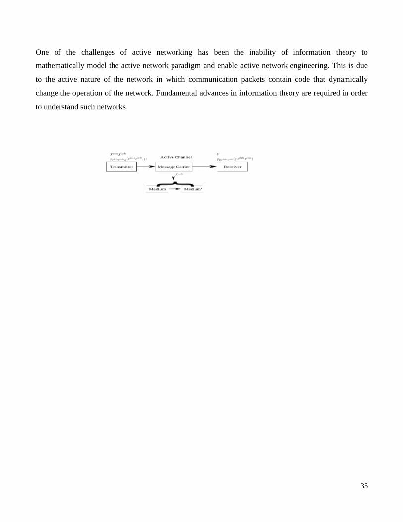
One of the challenges of active networking has been the inability of information theory to
mathematically model the active network paradigm and enable active network engineering. This is due
to the active nature of the network in which communication packets contain code that dynamically
change the operation of the network. Fundamental advances in information theory are required in order
to understand such networks
36
School of Computing
UNIT – II
Software Defined Networks – SCSA 3003
37
Open Flow Specification – Drawbacks of Open SDN, SDN via APIs, and SDN via Hypervisor-
Based Overlays – SDN via Opening up the Device – SDN Controllers – General Concepts
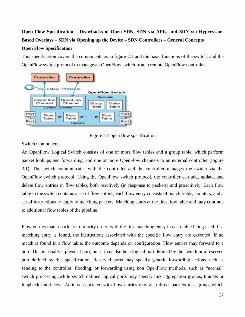
Open Flow Specification
This specification covers the components as in figure 2.1 and the basic functions of the switch, and the
OpenFlow switch protocol to manage an OpenFlow switch from a remote OpenFlow controller.
Figure 2.1 open flow specification
Switch Components
An OpenFlow Logical Switch consists of one or more flow tables and a group table, which perform
packet lookups and forwarding, and one or more OpenFlow channels to an external controller (Figure
2.1). The switch communicates with the controller and the controller manages the switch via the
OpenFlow switch protocol. Using the OpenFlow switch protocol, the controller can add, update, and
delete flow entries in flow tables, both reactively (in response to packets) and proactively. Each flow
table in the switch contains a set of flow entries; each flow entry consists of match fields, counters, and a
set of instructions to apply to matching packets. Matching starts at the first flow table and may continue
to additional flow tables of the pipeline.
Flow entries match packets in priority order, with the first matching entry in each table being used. If a
matching entry is found, the instructions associated with the specific flow entry are executed. If no
match is found in a flow table, the outcome depends on configuration. Flow entries may forward to a
port. This is usually a physical port, but it may also be a logical port defined by the switch or a reserved
port defined by this specification .Reserved ports may specify generic forwarding actions such as
sending to the controller, flooding, or forwarding using non OpenFlow methods, such as ―normal‖
switch processing ,while switch-defined logical ports may specify link aggregation groups, tunnels or
loopback interfaces . Actions associated with flow entries may also direct packets to a group, which
38
specifies additional processing
Groups represent sets of actions for flooding, as well as more complex forwarding semantics (e.g.
multipath, fast reroute, and link aggregation). As a general layer of indirection, groups also enable
multiple flow entries to forward to a single identifier (e.g. IP forwarding to a common next hop). This
abstraction allows common output actions across flow entries to be changed efficiently. The group table
contains group entries; each group entry contains a list of action buckets with specific semantics
dependent on group type.
The actions in one or more action buckets are applied to packets sent to the group. Switch designers are
free to implement the internals in any way convenient, provided that correct match and instruction
semantics are preserved. For example, while a flow entry may use an all group to forward to multiple
ports, a switch designer may choose to implement this as a single bitmask within the hardware
forwarding table. Another example is matching; the pipeline exposed by an OpenFlow switch may be
physically implemented with a different number of hardware tables.
• Action: an operation that acts on a packet. An action may forward the packet to a port, modify the
packet (such as decrementing the TTL field) or change its state (such as associating it with a queue).
Most actions include parameters, for example a set-field action includes a field type and field value.
Actions may be specified as part of the instruction set associated with a flow entry or in an action bucket
associated with a group entry. Actions may be accumulated in the Action Set of the packet or applied
immediately to the packet .
• List of Actions: an ordered list of actions that may be included in a flow entry in the ApplyActions
instruction or in a packet-out message, and that are executed immediately in the list order .
• Set of Actions: a set of actions included in a flow entry in the Write-Actions instruction that are added
to the action set, or in a group action-bucket that are executed in action-set order. Actions in a set can
occur only once.
• Action Bucket: a set of actions in a group. The group will select one or more buckets for each packet.
• Action Set: a set of actions associated with the packet that are accumulated while the packet is
processed by each table and that are executed in specified order when the instruction set terminates
pipeline processing
• Byte: an 8-bit octet.
39
• Connection: a network connection that carries OpenFlow messages between a switch and a controller,
it may be implemented using various network transport protocols. An OpenFlow channel has a main
connection, and optionally a number of auxiliary connections.
• Control Channel: The aggregation of components of an OpenFlow logical switch that manages
communication with controllers. The control channel includes one OpenFlow channel per OpenFlow
controller.
• Controller: see OpenFlow controller.
• Counter: counters are the main element of OpenFlow statistics and accumulated at various specific
points of the pipeline, such as on a port or on a flow entry. Counters typically count the number of
packets and bytes passing through an OpenFlow element, however other counters types are also defined.
• Datapath: the aggregation of components of an OpenFlow logical switch that are directly involved in
traffic processing and forwarding. The datapath includes the pipeline of flow tables, the group table and
the ports.
• Flow Entry: an element in a flow table used to match and process packets. It contains a set of match
fields for matching packets, a priority for matching precedence, a set of counters to track packets, and a
set of instructions to apply.
• Flow Table: a stage of the pipeline. It contains flow entries.
• Forwarding: Deciding the output port or set of output ports for a packet, and transfering that packet to
those output ports.
• Group: a list of action buckets and some means of choosing one or more of those buckets to apply on a
per-packet basis.
• Header: control information embedded in a packet used by a switch to identify the packet and to
inform the switch on how to process and forward the packet. The header typically includes various
header fields to identify the source and destination of the packet, and how to interpret other headers and
the payload.
• Header Field: a value from the packet header. The packet header is parsed to extract its header fields
which are matched against corresponding match fields.
• Hybrid: integrate both OpenFlow operation and normal Ethernet switching operation .
• Instruction: instructions are attached to a flow entry and describe the OpenFlow processing that
happens when a packet matches the flow entry. An instruction either modifies pipeline processing, such
as directing the packet to another flow table, or contains a set of actions to add to the action set, or
40
contains a list of actions to apply immediately to the packet.
• Instruction Set: a set of instructions attached to a flow entry in a flow table.
• Match Field: a part of a flow entry against which a packet is matched. Match fields can match the
various packet header fields, the packet ingress port, the metadata value and other pipeline A match field
may be wildcarded (match any value) and in some cases bitmasked (match subset of bits).
• Matching: comparing the set of header fields and pipeline fields of a packet to the match fields of a
flow entry.
• Metadata: a maskable register that is used to carry information from one table to the next.
• Message: OpenFlow protocol unit sent over an OpenFlow connection. May be a request, a reply, a
control message or a status event.
• Meter: a switch element that can measure and control the rate of packets. The meter triggers a meter
band if the packet rate or byte rate passing through the meter exceeds a predefined threshold . If the
meter band drops the packet, it is called a Rate Limiter.
• OpenFlow Channel: interface between an OpenFlow switch and an OpenFlow controller, used by the
controller to manage the switch.
• OpenFlow Controller: an entity interacting with the OpenFlow switch using the OpenFlow switch
protocol. In most case, an OpenFlow Controller is software which controls many OpenFlow Logical
Switches.
• OpenFlow Logical Switch: A set of OpenFlow resources that can be managed as a single entity,
includes a datapath and a control channel.
• OpenFlow Protocol: The protocol defined by this specification. Also called OpenFlow Switch
Protocol.
• OpenFlow Switch: See OpenFlow Logical Switch.
• Packet: a series of bytes comprising a header, a payload and optionally a trailer, in that order, and
treated as a unit for purposes of processing and forwarding. The default packet type is Ethernet, other
packet types are also supported.
• Pipeline: the set of linked flow tables that provide matching, forwarding, and packet modification in an
OpenFlow switch
• Pipeline fields: set of values attached to the packet during pipeline processing which are not header
fields. Include the ingress port, the metadata value, the Tunnel-ID value and others
• Port: where packets enter and exit the OpenFlow pipeline. May be a physical port, a logical port, or a

41
reserved port defined by the OpenFlow switch protocol.
• Queue: Schedule packets according to their priority on an output port to provide Quality-ofService
(QoS).
• Switch: See OpenFlow Logical Switch.
• Tag: a header that can be inserted or removed from a packet via push and pop actions.
• Outermost Tag: the tag that appears closest to the beginning of a packet.
OpenFlow Ports
OpenFlow ports are the network interfaces for passing packets between OpenFlow processing and the
rest of the network. OpenFlow switches connect logically to each other via their OpenFlow ports, a
packet can be forwarded from one OpenFlow switch to another OpenFlow switch only via an output
OpenFlow port on the first switch and an ingress OpenFlow port on the second switch. An OpenFlow
switch makes a number of OpenFlow ports available for OpenFlow processing. The set of OpenFlow
ports may not be identical to the set of network interfaces provided by the switch hardware, some
network interfaces may be disabled for OpenFlow, and the OpenFlow switch may define additional
OpenFlow ports.
OpenFlow packets are received on an ingress port and processed by the OpenFlow pipeline which may
forward them to an output port. The packet ingress port is a property of the packet throughout the
OpenFlow pipeline and represents the OpenFlow port on which the packet was received into the
OpenFlow switch. The ingress port can be used when matching packets.
The OpenFlow pipeline can decide to send the packet on an output port using the output action , which
defines how the packet goes back to the network. An OpenFlow switch must support three types of
OpenFlow ports: physical ports, logical ports and reserved ports.
Drawbacks of Open SDN
Disadvantages of SDN
Latency. Every device used on a network occupies a space on it. ...
Maintenance. The maintenance is a very important aspect of networking for carrying out its
operations. ...
Complexity. There isn't any standardized security protocols for SDN. ...
Configuration. ...

42
Device Security.
Why SDN is preferred over virtual networking?
The most notable difference between SDN and traditional networking is that SDN is software-based
while traditional networking is usually hardware-based. Because it's software-based, SDN is more
flexible, allowing users greater control and ease for managing resources virtually throughout the control
plane.
SDN via APIs
SDN implementation via APIs refers to southbound APIs that configure and program the control plane
active on the device. There are a number of legacy network device APIs in use that offer different
degrees of control (SNMP, CLO, TL1, RADIUS, TR-069, etc.) and a number of newer ones
(NETCONF/YANG, REST, XMPP, BGP-LS, etc.) that offer different degrees of control over the
network devices, data plane, topology, etc., each having different advantages and disadvantages. I won‘t
cover them in depth in this blog post but I want to make sure we all understand one key difference
between them and the Open SDN approach: OpenFlow is used to directly control the data plane, not just
the configuration of the devices and the control plane.
Figure 2.2 openflow API
In the networking world of today, we still configure most devices though a Command Line Interface
(CLI) by either connecting to the console of a device or through telnet/ssh of the device. Each device is
then configured individually. That has been networking configuration 101 for more than 25 years.
When a company decides to transform to a software defined networking infrastructure, they may not get
support from their existing Network hardware vendor, which may have been enjoying hefty margins in
network hardware sales and not thrilled to push a technology that will make their expensive boxes
replaceable for cheap vendor agnostic white boxes.
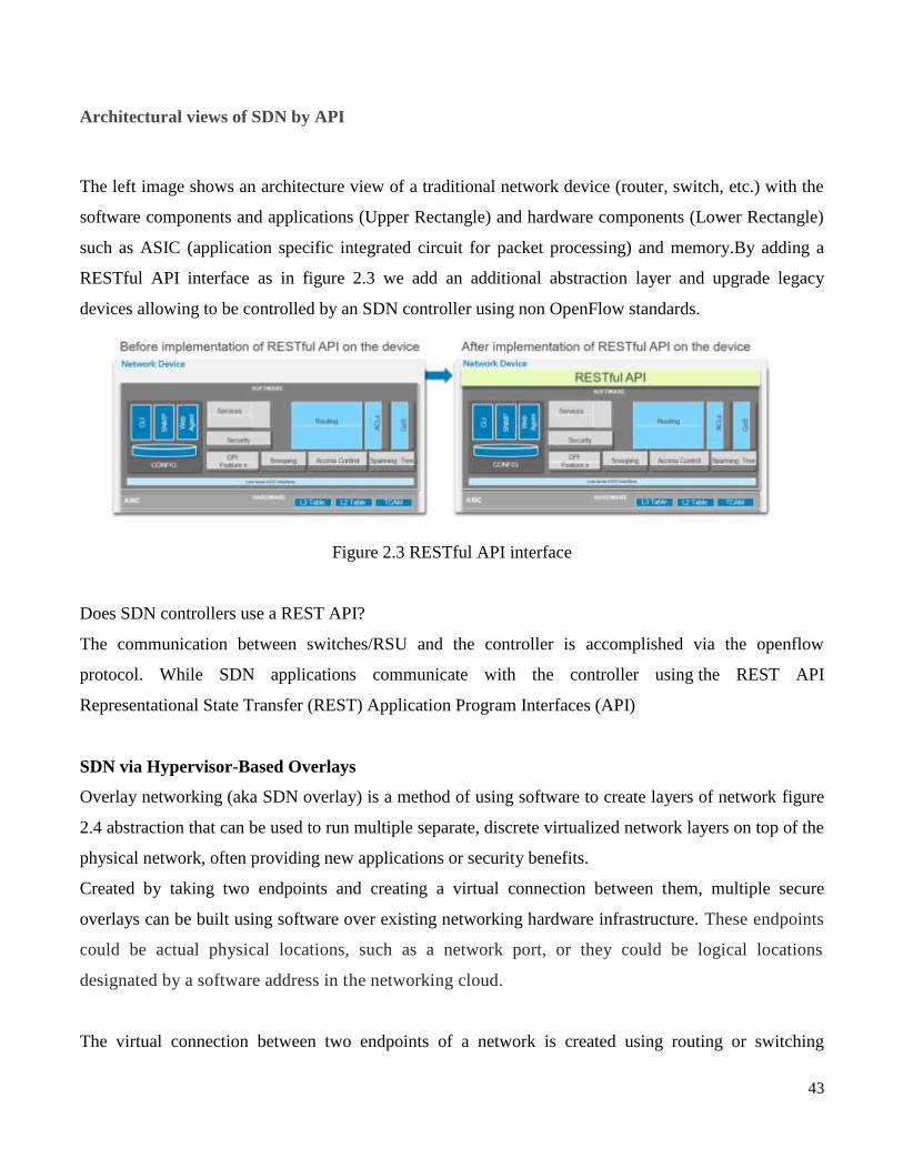
43
Architectural views of SDN by API
The left image shows an architecture view of a traditional network device (router, switch, etc.) with the
software components and applications (Upper Rectangle) and hardware components (Lower Rectangle)
such as ASIC (application specific integrated circuit for packet processing) and memory.By adding a
RESTful API interface as in figure 2.3 we add an additional abstraction layer and upgrade legacy
devices allowing to be controlled by an SDN controller using non OpenFlow standards.
Figure 2.3 RESTful API interface
Does SDN controllers use a REST API?
The communication between switches/RSU and the controller is accomplished via the openflow
protocol. While SDN applications communicate with the controller using the REST API
Representational State Transfer (REST) Application Program Interfaces (API)
SDN via Hypervisor-Based Overlays
Overlay networking (aka SDN overlay) is a method of using software to create layers of network figure
2.4 abstraction that can be used to run multiple separate, discrete virtualized network layers on top of the
physical network, often providing new applications or security benefits.
Created by taking two endpoints and creating a virtual connection between them, multiple secure
overlays can be built using software over existing networking hardware infrastructure. These endpoints
could be actual physical locations, such as a network port, or they could be logical locations
designated by a software address in the networking cloud.
The virtual connection between two endpoints of a network is created using routing or switching
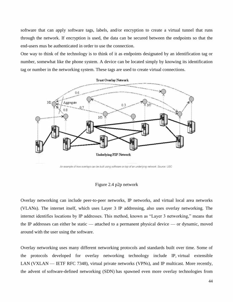
44
software that can apply software tags, labels, and/or encryption to create a virtual tunnel that runs
through the network. If encryption is used, the data can be secured between the endpoints so that the
end-users mus be authenticated in order to use the connection.
One way to think of the technology is to think of it as endpoints designated by an identification tag or
number, somewhat like the phone system. A device can be located simply by knowing its identification
tag or number in the networking system. These tags are used to create virtual connections.
Figure 2.4 p2p network
Overlay networking can include peer-to-peer networks, IP networks, and virtual local area networks
(VLANs). The internet itself, which uses Layer 3 IP addressing, also uses overlay networking. The
internet identifies locations by IP addresses. This method, known as ―Layer 3 networking,‖ means that
the IP addresses can either be static — attached to a permanent physical device — or dynamic, moved
around with the user using the software.
Overlay networking uses many different networking protocols and standards built over time. Some of
the protocols developed for overlay networking technology include IP, virtual extensible
LAN (VXLAN — IETF RFC 7348), virtual private networks (VPNs), and IP multicast. More recently,
the advent of software-defined networking (SDN) has spawned even more overlay technologies from
45
individual vendors, the most well known of which is VMware‘s NSX. Other emerging overlay solutions
for SDN architecture include Alcatel‘s Nuage Networks and Midokura. Network overlays enable
flexibility by allowing network managers to move around network endpoints using software
management.
Overlays and SDN
Different approaches to overlay networking are often debated in the SDN world. Depending on the
technique, software-only solutions may not have full control of the hardware, with chip-level
integration. One criticism of overlay networking is that it can create performance overhead by adding
more layers of software and processing. This occurs as specific software code or ―agents‖ must be
installed on the network to manage the SDN overlay, such as SDN controllers using the OpenFlow
protocol.
SDN via Opening up the Device
The physical separation of the network control plane from the forwarding plane, and where a control
plane controls several devices. Software-Defined Networking (SDN) is an emerging architecture that is
dynamic, manageable, cost-effective, and adaptable, making it ideal for the high-bandwidth, dynamic
nature of today‘s applications. This architecture decouples the network control and forwarding functions
enabling the network control to become directly programmable and the underlying infrastructure to be
abstracted for applications and network services. The OpenFlow® protocol is a foundational element for
building SDN solutions.
The SDN Architecture is:
DIRECTLY PROGRAMMABLE
Network control is directly programmable because it is decoupled from forwarding functions.
AGILE
Abstracting control from forwarding lets administrators dynamically adjust network-wide traffic flow to
meet changing needs.
CENTRALLY MANAGED
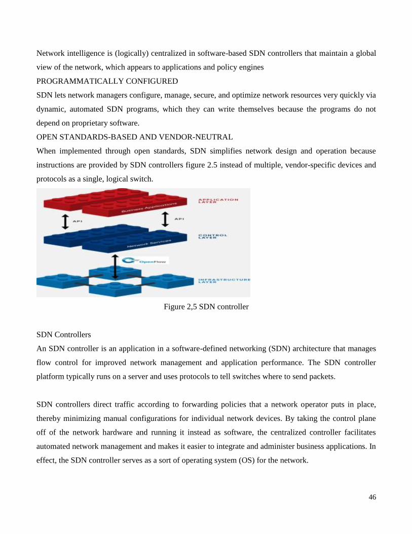
46
Network intelligence is (logically) centralized in software-based SDN controllers that maintain a global
view of the network, which appears to applications and policy engines
PROGRAMMATICALLY CONFIGURED
SDN lets network managers configure, manage, secure, and optimize network resources very quickly via
dynamic, automated SDN programs, which they can write themselves because the programs do not
depend on proprietary software.
OPEN STANDARDS-BASED AND VENDOR-NEUTRAL
When implemented through open standards, SDN simplifies network design and operation because
instructions are provided by SDN controllers figure 2.5 instead of multiple, vendor-specific devices and
protocols as a single, logical switch.
Figure 2,5 SDN controller
SDN Controllers
An SDN controller is an application in a software-defined networking (SDN) architecture that manages
flow control for improved network management and application performance. The SDN controller
platform typically runs on a server and uses protocols to tell switches where to send packets.
SDN controllers direct traffic according to forwarding policies that a network operator puts in place,
thereby minimizing manual configurations for individual network devices. By taking the control plane
off of the network hardware and running it instead as software, the centralized controller facilitates
automated network management and makes it easier to integrate and administer business applications. In
effect, the SDN controller serves as a sort of operating system (OS) for the network.

47
The controller is the core of a software-defined network. It resides between network devices at one end
of the network and applications at the other end. Any communication between applications and network
devices must go through the controller.The controller communicates with applications -- such as
firewalls or load balancers -- via northbound interfaces. The Open Networking Foundation
(ONF) created a working group in 2013 focused specifically on northbound APIs and their development.
The industry never settled on a standardized set, however, largely because application requirements vary
so widely.
The controller talks with individual network devices using a southbound interface, traditionally one like
the OpenFlow protocol. These southbound protocols allow the controller to configure network devices
and choose the optimal network path for application traffic. OpenFlow was created by ONF in 2011.
Pros and cons of SDN controllers.
One major benefit of SDN controllers is that the centralized controller is aware of all the available
network paths and can direct packets based on traffic requirements. Because of the controller's visibility
into the network, it can automatically modify traffic flows and notify network operators about congested
links.
Companies can -- and should -- use more than one controller, adding a backup for redundancy. Three
seems to be a common number among both commercial and open source SDN options. This redundancy
will enable the network to continue running in the event of lost connectivity or controller susceptibility.
The controller acts as a single point of failure, so securing it is pivotal to any software-defined network.
Whoever owns the controller has access to the entire network. This means network operators should
create security and authentication policies to ensure only the right people have access.

48
School of Computing
UNIT – III
Software Defined Networks – SCSA 3003
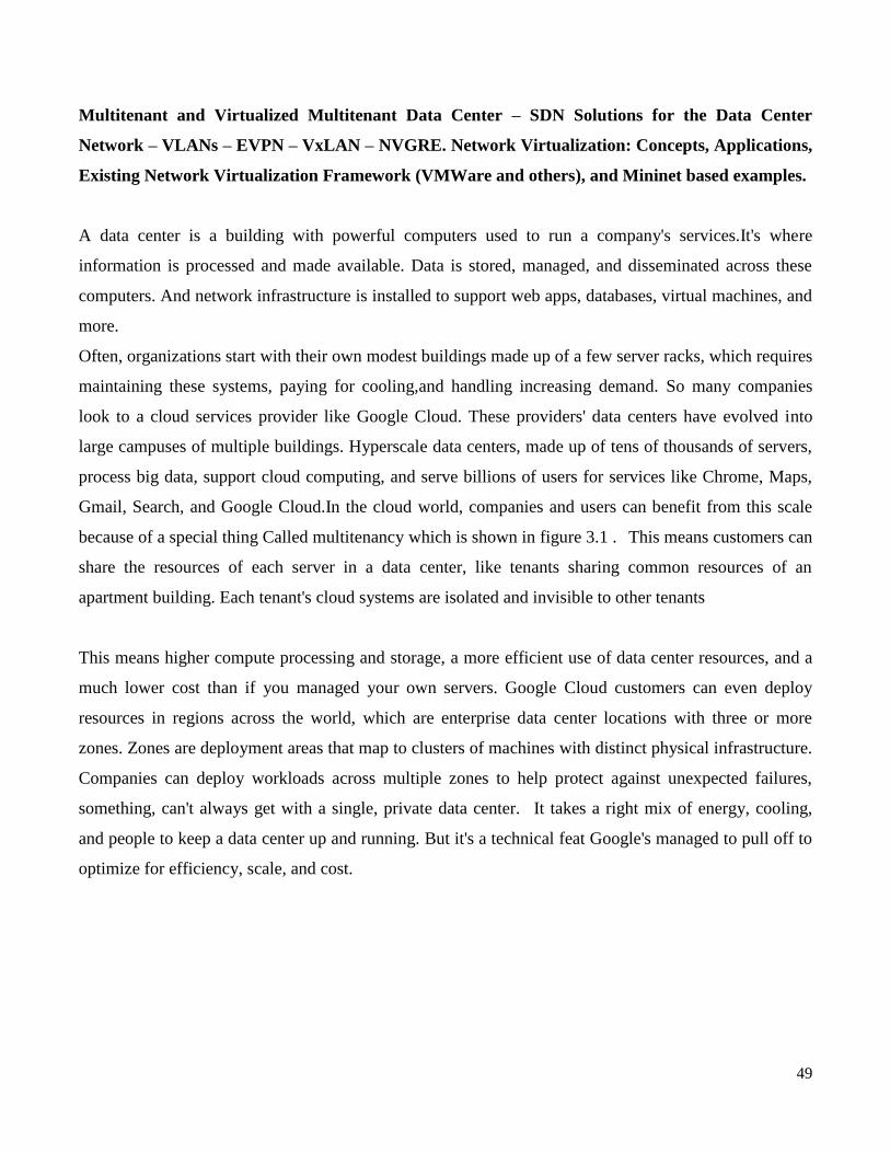
49
Multitenant and Virtualized Multitenant Data Center – SDN Solutions for the Data Center
Network – VLANs – EVPN – VxLAN – NVGRE. Network Virtualization: Concepts, Applications,
Existing Network Virtualization Framework (VMWare and others), and Mininet based examples.
A data center is a building with powerful computers used to run a company's services.It's where
information is processed and made available. Data is stored, managed, and disseminated across these
computers. And network infrastructure is installed to support web apps, databases, virtual machines, and
more.
Often, organizations start with their own modest buildings made up of a few server racks, which requires
maintaining these systems, paying for cooling,and handling increasing demand. So many companies
look to a cloud services provider like Google Cloud. These providers' data centers have evolved into
large campuses of multiple buildings. Hyperscale data centers, made up of tens of thousands of servers,
process big data, support cloud computing, and serve billions of users for services like Chrome, Maps,
Gmail, Search, and Google Cloud.In the cloud world, companies and users can benefit from this scale
because of a special thing Called multitenancy which is shown in figure 3.1 . This means customers can
share the resources of each server in a data center, like tenants sharing common resources of an
apartment building. Each tenant's cloud systems are isolated and invisible to other tenants
This means higher compute processing and storage, a more efficient use of data center resources, and a
much lower cost than if you managed your own servers. Google Cloud customers can even deploy
resources in regions across the world, which are enterprise data center locations with three or more
zones. Zones are deployment areas that map to clusters of machines with distinct physical infrastructure.
Companies can deploy workloads across multiple zones to help protect against unexpected failures,
something, can't always get with a single, private data center. It takes a right mix of energy, cooling,
and people to keep a data center up and running. But it's a technical feat Google's managed to pull off to
optimize for efficiency, scale, and cost.
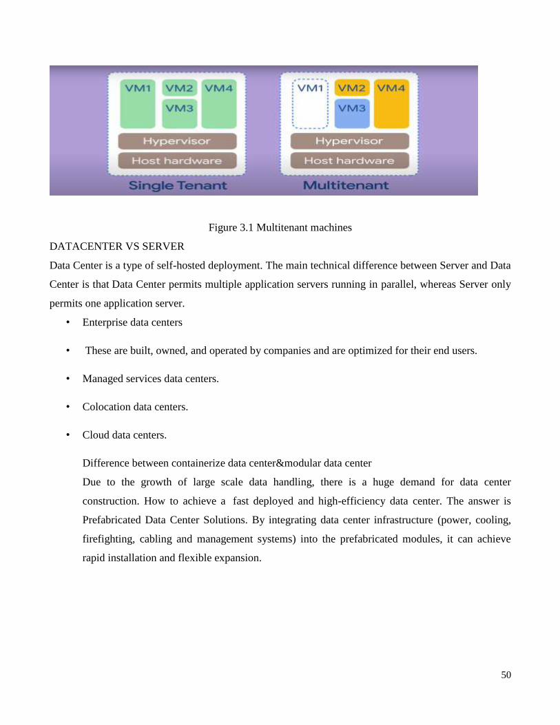
50
Figure 3.1 Multitenant machines
DATACENTER VS SERVER
Data Center is a type of self-hosted deployment. The main technical difference between Server and Data
Center is that Data Center permits multiple application servers running in parallel, whereas Server only
permits one application server.
• Enterprise data centers
• These are built, owned, and operated by companies and are optimized for their end users.
• Managed services data centers.
• Colocation data centers.
• Cloud data centers.
Difference between containerize data center&modular data center
Due to the growth of large scale data handling, there is a huge demand for data center
construction. How to achieve a fast deployed and high-efficiency data center. The answer is
Prefabricated Data Center Solutions. By integrating data center infrastructure (power, cooling,
firefighting, cabling and management systems) into the prefabricated modules, it can achieve
rapid installation and flexible expansion.
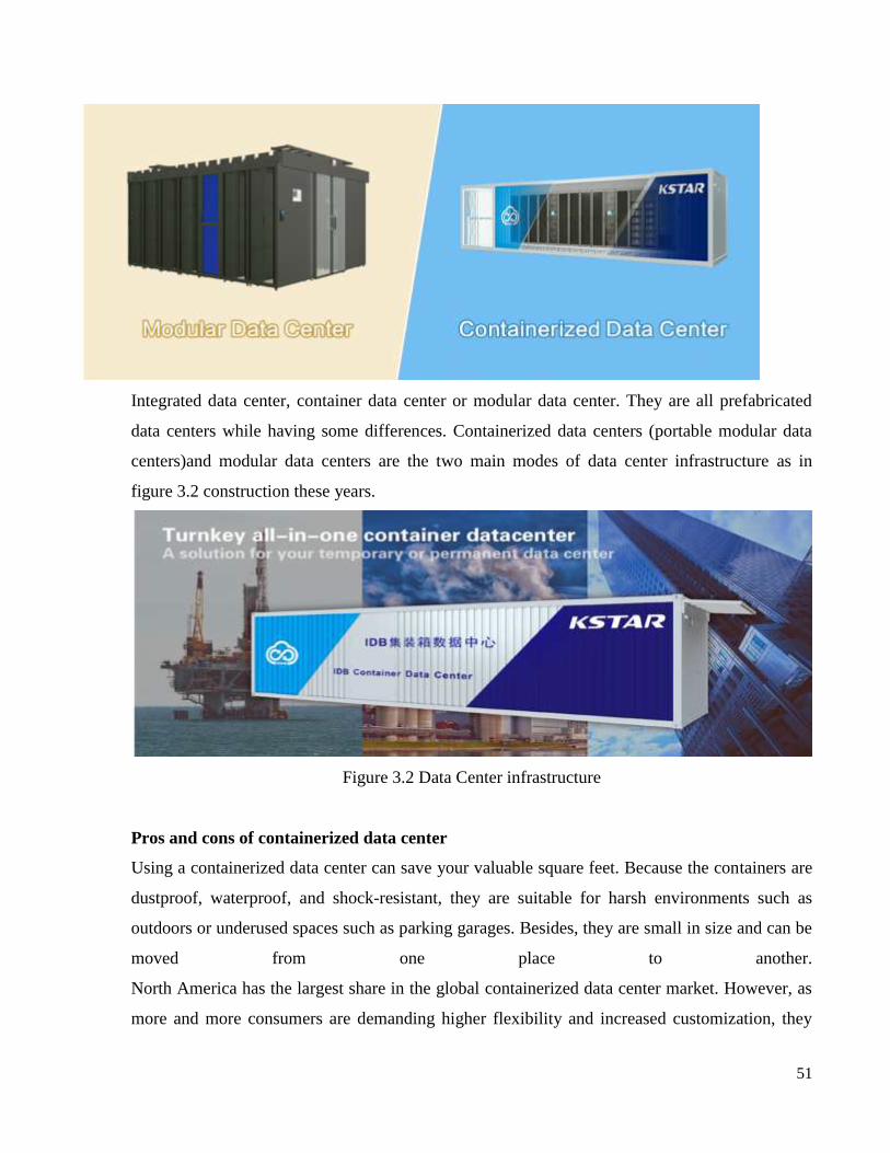
51
Integrated data center, container data center or modular data center. They are all prefabricated
data centers while having some differences. Containerized data centers (portable modular data
centers)and modular data centers are the two main modes of data center infrastructure as in
figure 3.2 construction these years.
Figure 3.2 Data Center infrastructure
Pros and cons of containerized data center
Using a containerized data center can save your valuable square feet. Because the containers are
dustproof, waterproof, and shock-resistant, they are suitable for harsh environments such as
outdoors or underused spaces such as parking garages. Besides, they are small in size and can be
moved from one place to another.
North America has the largest share in the global containerized data center market. However, as
more and more consumers are demanding higher flexibility and increased customization, they

52
are turning to the modular data center solution. Containerized data center is losing the market
share for its limited space for expansion and limited computational efficiency.
Modular data center solutions are installed on the floor like traditional data center but it saves
lots of space because of its all-in-one design.Each component of the data center is an
independent enclosed space, which contains air-conditioning, PDU equipment and fire-fighting
equipment. For small modular data center(the cabinet is within 10 and total load is less than 40kVA), a
closed isolation scheme of the cold and hot aisle is adopted for the series with excellent
compatibility, the high utilization rate of cooling capacity, and energy-saving. For medium data
center closed cold aisle or hot aisle or closed cold and hot aisle is optional. It is recommended to
adopt a variable frequency energy-saving in row air conditioner to eliminate local hot spots,
enhance the bearing load capacity of the single IT cabinet, isolate cold and hot air and decrease
energy consumption. These excellent cooling designs make the modular data center more energy
efficient.
Compared with the containerize data center there is not a limited capacity for the number of
racks or the total power for the IT load. Not to mention that the spacious space is more
convenient for engineers to do maintenance work than narrow containers. it is safer. Because of
its flexibility, convenience, and easy expansion characteristics, Modular data centers are widely
used in dot-com companies. In particular, many dot-com companies directly rent some cabinets
in the operator's data center computer room to develop their own business.
Individual data centers are also rapidly adopted among enterprises to enhance operational
efficiency In 2019, individual facilities accounted for over 70% share in the China modular data
center market and is expected to witness 17% growth through 2026.(source: Modular Data
Center Market Size & Share - Global Report 2026)
Any entity that generates or uses data has the need for data centers on some level,
including government agencies, educational bodies, telecommunications companies, financial
institutions, retailers of all sizes, and the purveyors of online information and social networking
services such as Google and Facebook.
Data centers are simply centralized locations where computing and networking equipment is
53
concentrated for the purpose of collecting, storing, processing, distributing or allowing access to
large amounts of data .They provide important services such as data storage, backup and
recovery, data management and networking.
In the days of the room-sized behemoths that were our early computers, a data center might have
had one supercomputer. As equipment got smaller and cheaper, and data processing needs began
to increase -- and they have increased exponentially.we started networking multiple servers (the
industrial counterparts to our home computers) together to increase processing power.
We connect them to communication networks so that people can access them, or the information
on them, remotely. Large numbers of these clustered servers and related equipment can be
housed in a room, an entire building or groups of buildings. Today's data center is likely to have
thousands of very powerful and very small servers running 24/7.
Because of their high concentrations of servers, often stacked in racks that are placed in rows,
data centers are sometimes referred to a server farms. They provide important services such as
data storage, backup and recovery, data management and networking.
• These centers can
• store and serve up Web sites,
• run e-mail and instant messaging (IM) services,
• provide cloud storage and applications,
• enable e-commerce transactions,
• power online gaming communities and do a host of other things that require the wholesale
crunching of zeroes and ones.
• Some build and maintain them in-house,
• some rent servers at co-location facilities (also called colos)
• and some use public cloud-based services at hosts like Amazon, Microsoft, Sony and Google.
• The colos and the other huge data centers began to spring up in the late 1990s and early 2000s,
sometime after Internet usage went mainstream.

54
• Study by International Data Corporation for EMC estimated that 1.8 trillion gigabytes (GB), or
around 1.8 zettabytes (ZB),
• of digital information was created in 2011 [sources: Glanz, EMC, Phneah].
• The amount of data in 2012 was approximately 2.8 ZB and is expected to rise to 40 ZB by the
year 2020 [sources: Courtney, Digital Science Series, EMC].
• When we think of data centers, many of us envision huge warehouses full of racks of servers,
blinking and humming away, wires running to and fro. And in some cases we'd be right. But they
come in all shapes, sizes and configurations. They range from a few servers in a room to huge
standalone structures measuring hundreds of thousands of square feet with tens of thousands of
servers and other accompanying hardware. Their sizes and the types of equipment they contain
vary depending upon the needs of the entity or entities they are supporting.
• heavy online presences have large data centers located all over the world, including Google,
Facebook, Microsoft, AOL and Amazon. Microsoft reportedly adds 20,000 servers monthly
[source: Uddin], Google has around 50,000 servers at just one of its many sites [source: Levy].
• Google has thirteen big data centers, including locations in Douglas County,
• Ga.; Lenoir, N.C.; Berkeley County, S.C.; Council Bluffs, Iowa; Mayes County, Okla.;
• The Dalles, Ore.;
• Quilicura, Chile;
• Hamina, Finland; St. Ghislain, Belgium;
• Dublin, Ireland;
• Hong Kong, Singapore and Taiwan; as well as lots of mini data centers, some even in co-location
sites.
The Telecommunication Industry Association developed a data center tier classification standard in
2005 called the TIA-942 project, which identified four categories of data center, rated by metrics
like redundancy and level of fault tolerance.

55
• Tier 1 - Basic site infrastructure with a single distribution path that has no built-in redundancy.
• Tier 2 - Redundant site infrastructure with a single distribution path that includes redundant
components.
• Tier 3 - Concurrently maintainable site infrastructure that has multiple paths, only one of which
is active at a time.
• Tier 4 - Fault tolerant site infrastructure that has multiple active distribution paths for lots of
redundancy. [Sources: DiMinico, Uddin]
• sites that fall into tier 1 and 2 categories have to shut down for maintenance occasionally, while
tier 3 and 4 sites should be able to stay up during maintenance and other interruptions. A higher
number translates to both a higher level of reliability (meaning less potential downtime) and a
higher cost.
One physical commonality of data centers is clusters of interconnected servers. They might all be
very similar, stacked up neatly in open racks or closed cabinets of equal height, width and depth,
or there could be a bunch of different types, sizes and ages of machines coexisting, such as small
flat modern servers alongside bulky old Unix boxes and giant mainframes (a fast disappearing
breed .
Each server is a high performance computer, with memory, storage space, a processor or
processors and input/output capability, kind of like a souped-up version of a personal computer,
but with a faster and more powerful processor and a lot more memory, and usually without a
monitor, keyboard or the other peripherals you would use at home .
• Monitors might exist in a centralized location, nearby or in a separate control room, for
monitoring groups of servers and related equipment Data centers are an integral part of the
enterprise, designed to support business applications and provide services such as:
• Data storage, management, backup and recovery
• Productivity applications, such as email
• High-volume e-commerce transactions
• Powering online gaming communities Big data, machine learning and artificial intelligence
56
primary elements of a data center
• Facility – the usable space available for IT equipment.
• Providing round-the-clock access to information makes data centers some of the world‘s most
energy-consuming facilities.
• Design to optimize space and environmental control to keep equipment within specific
temperature/humidity ranges are both emphasized.
• Core components – equipment and software for IT operations and storage of data and
applications.
• These may include storage systems;
• servers; network infrastructure, such as switches and routers;
• and various information security elements, such as firewalls.
• Support infrastructure – equipment contributing to securely sustaining the highest availability
possible. The Uptime Institute has defined four tiers of data centers, with availability ranging
from 99.671% to 99.995%.
• Some components for supporting infrastructure include:
– Uninterruptible Power Sources (UPS) – battery banks, generators and redundant power
sources.
– Environmental control – computer room air conditioners (CRAC); heating, ventilation
and air conditioning (HVAC) systems; and exhaust systems.
– Physical security systems – biometrics and video surveillance systems.
– Operations staff – personnel available to monitor operations and maintain IT and
infrastructure equipment around the clock.
• Data center needs. What are the specific shortcomings that exist in data center networks
today?
57
• Data center technologies. What technologies are employed in the data center, both now and with
the advent of SDN?
• Data center use cases. What are some specific applications of SDN in the data center?
• Densely packed racks of high-powered computers and storage have been around for
decades,originally providing environments for mainframes, the density of those servers and the
arrays of storage that served them have made it possible to host a tremendous amount of compute
power in a single room or pod .
Today‘s data centers hold thousands, even tens of thousands, of physical servers.
• These data centers can be segregated into the following three categories:
• Private single-tenant
• Private multitenant
• Public multitenant
Private single-tenant.
Individual organizations that maintain their own data centers belong in this category. The data center is
for the private use of the organization, there is only the one organization or tenant using the data center.
Private multitenant.
Organizations that provide specialized data center services on behalf of other client organizations belong
in this category. IBM and EDS (now HP) are examples of companies that host such data centers. These
centers are built and maintained by the organization providing the service, and multiple clients store data
there, suggesting the term multitenant.These data centers are private because they offer their services
contractually to specific clients .
Public multitenant.
Organizations that provide generalized data center services to any individual or organization belong in

58
this category. Examples of companies that provide these services include Google and Amazon. These
data centers offer their services to the public. Anybody, whether individuals or organizations, who wants
to use these services may access them via the web. These types of data centers are often referred to as
residing in the cloud.
Three subcategories of clouds are in common use: public clouds, private clouds, and hybrid clouds. In a
public cloud, a service provider or other large entity makes services available to the general public over
the Internet. Such services may include a wide variety of applications or storage services, among other
things. Examples of public cloud offerings include Microsoft Azure Services Platform and Amazon
Elastic Compute Cloud.
In a private cloud, a set of server and network resources is assigned to one tenant exclusively and
protected behind a firewall specific to that tenant. The physical resources of the cloud are owned and
maintained by the cloud provider, which may be a distinct entity from the tenant. The physical
infrastructure may be managed using a product such as VMware‘s vCloud. Amazon Web Services is an
example of the way a private cloud may also be hosted by a third party (i.e., Amazon)
Combining the increasing density of servers and storage and the rise in networking speed and
bandwidth, the trend has been to host more and more information in ever-larger data centers. Add to that
enterprises‘ desire to reduce operational costs, and we find that merging many data centers into a larger
single data center is the natural result.
Datacenter demands
• Overcoming Current Network Limitations
• Adding, Moving, and Deleting Resources
• Failure Recovery
• Multitenancy
• Traffic Engineering and Path Efficiency

59
• Networking protocols were coupled with physical ports. The dynamic nature and sheer number
of VMs in the data center have placed demands on the capacity of network components.
• MAC Address Explosion
• Number of VLANs
• Spanning Tree
• In switches and routers, the device uses MAC address table to quickly determine the port or
interface out of which the device should forward the packet. For speed, this table is implemented
in hardware. As such, it has a physical limit to its size. N ,with network virtualization and the use
of Ethernet technology across WANs, the layer two networks are being stretched geographically
as never before. With server virtualization, the number of servers possible in a single layer two
network has increased dramatically. With numerous virtual network interface cards (NICs) on
each virtual server, this problem of a skyrocketing number of MAC addresses is exacerbated.
This has the benefit of ensuring that the frame reaches its destination if that destination exists on
the layer two networks. When the destination receives that initial frame, this prompts a response
from the destination. Upon receipt of the response, the switch is able to learn the port on which
that MAC address is located and populates its MAC table accordingly .
Figure 3.3 VLAN
let us take a closer VLAN-centric look at Figure 3.3
When a VLAN-tagged packet fails its match, it is flooded out only to all ports on that VLAN,
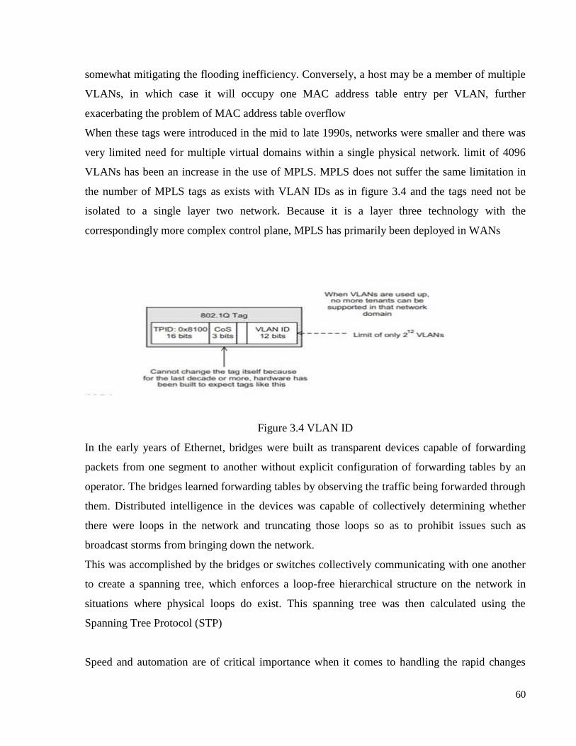
60
somewhat mitigating the flooding inefficiency. Conversely, a host may be a member of multiple
VLANs, in which case it will occupy one MAC address table entry per VLAN, further
exacerbating the problem of MAC address table overflow
When these tags were introduced in the mid to late 1990s, networks were smaller and there was
very limited need for multiple virtual domains within a single physical network. limit of 4096
VLANs has been an increase in the use of MPLS. MPLS does not suffer the same limitation in
the number of MPLS tags as exists with VLAN IDs as in figure 3.4 and the tags need not be
isolated to a single layer two network. Because it is a layer three technology with the
correspondingly more complex control plane, MPLS has primarily been deployed in WANs
Figure 3.4 VLAN ID
In the early years of Ethernet, bridges were built as transparent devices capable of forwarding
packets from one segment to another without explicit configuration of forwarding tables by an
operator. The bridges learned forwarding tables by observing the traffic being forwarded through
them. Distributed intelligence in the devices was capable of collectively determining whether
there were loops in the network and truncating those loops so as to prohibit issues such as
broadcast storms from bringing down the network.
This was accomplished by the bridges or switches collectively communicating with one another
to create a spanning tree, which enforces a loop-free hierarchical structure on the network in
situations where physical loops do exist. This spanning tree was then calculated using the
Spanning Tree Protocol (STP)
Speed and automation are of critical importance when it comes to handling the rapid changes
61
demanded by virtualized servers and storage. It is clearly important that changes to networking
infrastructure take place at the same rate as is possible with servers and storage. Legacy networks
require days or weeks for significant changes to VLANs and other network plumbing needs.
The size and scale of data centers today make recovery from failure a complex task, and the
ramifications of poor recovery decisions are only magnified as scale grows. Determinism,
predictability, and optimal re-configuration are among the most important recovery-related
considerations. With the distributed intelligence of today‘s networks, recovery from failures
results in unpredictable behavior. It is desirable that the network move to a known state, given a
particular failure
Data center consolidation has resulted in more and more clients occupying the same set of
servers, storage, and network. The challenge is to keep those individual clients separated and
insulated from each other and to utilize network bandwidth efficiently. In a large multitenant
environment, it is necessary to keep separate the resources belonging to each client
• With a small number of tenants in a data center, it was possible to arrange traffic and bandwidth
allocation using scripts. However, in an environment with hundreds (a large data center) or
thousands (a cloud) of tenants with varying needs and schedules, a more fluid and robust
mechanism is required to manage traffic loads. As data centers have grown, so has the need to
make better use of the resources being shared by all the applications and processes using the
physical infrastructure. Proper use of monitoring and measurement tools for more informed
calculation of the paths that network traffic takes as it makes its way through the physical
network.
State-of-the-art methods of calculating routes use link-state technology, which provides the
network topology for the surrounding network devices that are part of the same
autonomous system (AS).
One of the reasons for the increasing attention on traffic engineering and path efficiency in the
data center has been the rise of East-West traffic relative to North-South traffic.East-West traffic
is composed of packets sent by one host in a data center to another host in that same data center.

62
Analogously, North-South traffic is traffic entering (leaving) the data center from (to) the outside
world .
Three main technologies are being used today to address many of the data center needs.These
tunneling methods are
• Virtual eXtensible Local Area Network (VXLAN) ,
• Network Virtualization using Generic Routing Encapsulation (NVGRE),
• and Stateless Transport Tunneling (STT)
the fact that the packets are encapsulated as they transit the physical network does reduce the
maximum transmission unit (MTU) size, and the host software must be reconfigured tunneling
methods may be used to form the tunnels that knit together the virtual tunnel endpoints (VTEPs)
in an SDN via hypervisor-based overlays system
VXLAN
The VXLAN technology was developed primarily by VMware and Cisco as a means to mitigate
the inflexibility and limitations of networking technology. Some of the main characteristics of
VXLAN are:
• VXLAN utilizes MAC-in-IP tunneling.
• Each virtual network or overlay is called a VXLAN segment as in figure 3.5
Figure 3.5 VXLAN header
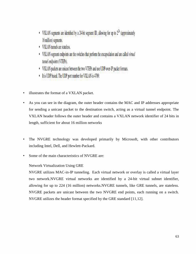
63
• illustrates the format of a VXLAN packet.
• As you can see in the diagram, the outer header contains the MAC and IP addresses appropriate
for sending a unicast packet to the destination switch, acting as a virtual tunnel endpoint. The
VXLAN header follows the outer header and contains a VXLAN network identifier of 24 bits in
length, sufficient for about 16 million networks
• The NVGRE technology was developed primarily by Microsoft, with other contributors
including Intel, Dell, and Hewlett-Packard.
• Some of the main characteristics of NVGRE are:
Network Virtualization Using GRE
NVGRE utilizes MAC-in-IP tunneling. Each virtual network or overlay is called a virtual layer
two network.NVGRE virtual networks are identified by a 24-bit virtual subnet identifier,
allowing for up to 224 (16 million) networks.NVGRE tunnels, like GRE tunnels, are stateless.
NVGRE packets are unicast between the two NVGRE end points, each running on a switch.
NVGRE utilizes the header format specified by the GRE standard [11,12].
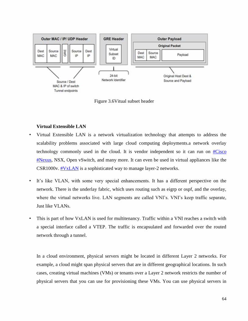
64
Figure 3.6Vitual subset header
Virtual Extensible LAN
• Virtual Extensible LAN is a network virtualization technology that attempts to address the
scalability problems associated with large cloud computing deployments.a network overlay
technology commonly used in the cloud. It is vendor independent so it can run on #Cisco
#Nexus, NSX, Open vSwitch, and many more. It can even be used in virtual appliances like the
CSR1000v. #VxLAN is a sophisticated way to manage layer-2 networks.
• It‘s like VLAN, with some very special enhancements. It has a different perspective on the
network. There is the underlay fabric, which uses routing such as eigrp or ospf, and the overlay,
where the virtual networks live. LAN segments are called VNI‘s. VNI‘s keep traffic separate,
Just like VLANs.
• This is part of how VxLAN is used for multitenancy. Traffic within a VNI reaches a switch with
a special interface called a VTEP. The traffic is encapsulated and forwarded over the routed
network through a tunnel.
In a cloud environment, physical servers might be located in different Layer 2 networks. For
example, a cloud might span physical servers that are in different geographical locations. In such
cases, creating virtual machines (VMs) or tenants over a Layer 2 network restricts the number of
physical servers that you can use for provisioning these VMs. You can use physical servers in
65
different Layer 2 networks for provisioning VMs. However, as the migration between different
servers is restricted to the same Layer 2 network, the utilization of the physical resource is not
optimized.
VXLAN is a Layer 2 technology that enables you to create a Layer 2 network on top of a Layer 3
network, thereby providing further network isolation. VXLAN provides a virtual Layer 2
network that stretches over multiple physical Layer 2 networks. Therefore, provisioning
resources in a cloud environment is not restricted to a single physical Layer 2 network. Physical
servers can be a part of a VXLAN network as long as they are connected by IPv4 or IPv6
networks.
The VXLAN base case is to connect two or more layer three network domains and make them
look like a common layer two domain.This allows virtual machines on different networks to
communicate as if they were in the same layer 2 subnet. For the most part, networking devices
process VXLAN traffic transparently.
• Does VXLAN replace VLAN?
When a switch performs the VTEP functions, it is referred to as a VxLAN Gateway. The
switches can perform VxLAN encapsulation/decapsulation and can also translate the VLAN ID
to VNI.an use the VXLAN technology with the Elastic Virtual Switch (EVS) feature of Oracle
Solaris to create a large number of virtual networks.Increases scalability in virtualized cloud
environments as the VXLAN ID is 24 bits, which enables you to create up to 16 million isolated
networks. This overcomes the limitation of VLANs having the 12 bits VLAN ID, which enables
you to create a maximum of 4094 isolated networks.
Enables you to use the Layer 3 features of the underlying network.The virtual Layer 2 network is
abstracted from the underlying physical network. As a result, the virtual network is not visible to
the physical network and provides the following benefits:
• Removes the need to have additional physical infrastructure.
• For example, the forwarding table of the external switch does not grow with the increase
in the VMs behind the physical port on the server.
• Reduces the scope of MAC address duplication to VMs that exists in the same VXLAN
segment.
66
• The MAC address can overlap when the addresses are not a part of the same VXLAN
segment.
• In a VXLAN, only the MAC address of the datalink that belong to the same VXLAN
segment or VNI must be unique.
• This is similar to a VLAN where the VLAN ID and the MAC address must have a
unique combination.
In Oracle Solaris, a VXLAN endpoint is represented by a VXLAN datalink. This VXLAN
datalink is associated with an IP address (IPv4 or IPv6) and a VXLAN network identifier (VNI).
Even though multiple VXLAN datalinks can use the same IP address, the combination of the IP
address and VNI must be unique. You can configure a VXLAN datalink with an optional
multicast address, which is used for discovering the peer VXLAN endpoints on the same VNI
and also to implement broadcast within a VXLAN segment. VXLAN datalinks in the same VNI
must be configured with the same multicast address.
VXLAN Topology
VXLAN enables you to organize systems on a Layer 3 network within their own VXLAN
segments.The following figure illustrates a VXLAN network that is configured over multiple
physical servers.
The main difference is that VLAN uses the tag on the layer 2 frame for encapsulation and can
scale up to 4000 VLANs. VXLAN, on the other hand, encapsulates the MAC in UDP and is
capable of scaling up to 16 million VxLAN segments.
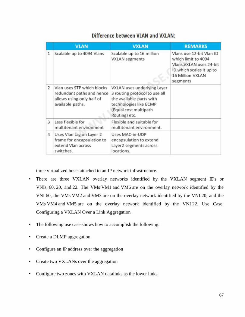
67
three virtualized hosts attached to an IP network infrastructure.
• There are three VXLAN overlay networks identified by the VXLAN segment IDs or
VNIs, 60, 20, and 22. The VMs VM1 and VM6 are on the overlay network identified by the
VNI 60, the VMs VM2 and VM3 are on the overlay network identified by the VNI 20, and the
VMs VM4 and VM5 are on the overlay network identified by the VNI 22. Use Case:
Configuring a VXLAN Over a Link Aggregation
• The following use case shows how to accomplish the following:
• Create a DLMP aggregation
• Configure an IP address over the aggregation
• Create two VXLANs over the aggregation
• Configure two zones with VXLAN datalinks as the lower links
68
Ethernet Virtual Private Network (EVPN) is a Layer 2 VPN technology that provides both Layer
2 and Layer 3 connectivity between distant network sites across an IP network. EVPN uses MP-
BGP in the control plane and VXLAN in the data plane. EVPN is typically used in data centers
for multitenant services.
• VXLAN gateway: A VXLAN gateway bridges traffic between VXLAN and non-VXLAN
environments by becoming a virtual network endpoint.
• For example, it can link a traditional VLAN and a VXLAN network,
• VXLAN segment: A VXLAN segment is a Layer 2 overlay network over which VMs
communicate.
Only VMs within the same VXLAN segment can communicate with each other.
• VNI: The Virtual Network Identifier (VNI), also referred to as VXLAN segment ID.
• The system uses the VNI, along with the VLAN ID, to identify the appropriate tunnel.
• VTEP: The VXLAN Tunnel Endpoint (VTEP) terminates a VXLAN tunnel.
• The same local IP address can be used for multiple tunnels.
• VXLAN header: In addition to the UDP header, encapsulated packages include a VXLAN
header, which carries a 24-bit VNI to uniquely identify Layer 2 segments within the overlay.
• VXLAN is developed to provide the same Ethernet Layer 2 network services as VLAN does
today, but with greater extensibility and flexibility. When it comes to segment your networks,
VXLAN functions just like VLAN and possesses advantages VLAN don‘t have.
• EVPN provides the following benefits:
• Configuration automation—MP-BGP automates VTEP discovery, VXLAN tunnel
establishment, and VXLAN tunnel assignment to ease deployment.
• Separation of the control plane and the data plane—EVPN uses MP-BGP to advertise host
reachability information in the control plane and uses VXLAN to forward traffic in the data
plane.

69
• Integrated routing and bridging (IRB)—MP-BGP advertises both Layer 2 and Layer 3 host
reachability information to provide optimal forwarding paths and minimize flooding.
EVPN uses the VXLAN technology for traffic forwarding in the data plane. The transport edge
devices assign user terminals to different VXLANs, and then forward traffic between sites for
user terminals by using VXLAN tunnels. The transport edge devices are VXLAN tunnel
endpoints (VTEPs).
70
School of Computing
UNIT – IV
Software Defined Networks – SCSA 3003
71
Programming SDNs: Northbound Application Programming Interface, Current Languages and Tools, Composition
of SDNs – Network Functions Virtualization (NFV) and Software Defined Networks: Concepts, Implementation and
Applications.
A northbound interface is an interface that allows a particular component of a network to
communicate with a higher-level component. Conversely, a southbound interface allows a
particular network component to communicate with a lower-level component. Examples of the
types of network applications that can be optimized via the northbound interface include load
balancers, firewalls, or other software-defined security services, or orchestration applications
across cloud resources.
Northbound integration is usually implemented through the following interfaces: Extensible
Markup Language (XML) File Transfer Protocol (FTP) SNMP, System Log (SYSLOG).With the
proliferation of UC services and applications in today‘s business landscape, integration is more important
than ever in enabling these to be centrally coordinated and in order to automate your business processes.
There is a lot of talk about integration between UC systems generally; with organizations considering
open architectures, APIs, and middleware to achieve better business outcomes. In this blog we‘ll take
a look at how those concepts are implemented in VOSS-4-UC, and how they can be leveraged to
manage your UC environment and to incorporate UC into your wider business processes.
In VOSS-4-UC, integration is a central part of the product‘s architecture. Let‘s explore what those
capabilities are and how they help drive UC automation.
Southbound interfaces
VOSS-4-UC includes an extensive and ever growing suite of integrations that come out of the box,
along with corresponding features that automate UC management tasks. Some recent additions
include integrations to Broadworks, Cisco UCCX and UCCE, Expressway, Cisco IOS XE, Imagicle,
and Microsoft Teams.
In addition, VOSS-4-UC includes a generic driver capability that can define an integration to
virtually any application. This can be via an API for applications that provide one, however we still
encounter a lot of applications that don‘t provide an API or provide partial coverage in their APIs. So
for these scenarios we have a GUI orchestration capability so that steps via the application‘s portal
can still be automated.
Once an integration to an application has been configured, organizations can use this to automate
tasks in the VOSS-4-UC portal, in the bulk loader, and of course in our own API. This is one of the
key enablers in VOSS-4-UC‘s ability to drive automation extension by easily and rapidly expanding
the applications and devices that can be incorporated into workflow automation.
Northbound interfaces
VOSS-4-UC provides extensive capabilities to interact with upstream systems, including a
comprehensive and secure REST API interface that provides a single point of integration for external
applications to interface between VOSS-4-UC and the UC solution.
The northbound notification interface provides the ability to push data to upstream systems based on
activities in VOSS-4-UC. This ensures those upstream systems are kept up to date with information
needed in near-real time when that data changes in VOSS-4-UC.
The flexibility in VOSS-4-UC means that interfaces can be simple and tailored to the needs of the
integration, which significantly increases the ease and speed with which the integration can be
achieved. This also keeps the detailed UC logic and business rules outside of the integration which
means the API interface doesn‘t need to be impacted when the logic changes to meet evolving
72
business needs. The fact that the integration interface isn‘t impacted saves significant costs and time
in implementing the changes.
What can these integration capabilities do for you?
With the extensive northbound and southbound capabilities, VOSS-4-UC can act as the perfect UC
middleware layer that bridges your upstream business applications with the UC applications that
deliver the collaboration needs for your users.
Let‘s take a look at a few examples of how these integration capabilities are being used by our
customers today, and the benefits they are realizing.
Flow-through Provisioning
Zero touch provisioning can tie UC fulfillment tasks in VOSS-4-UC to business activities in the
external systems for automated fulfillment. Some examples include directory changes initiating
onboarding/offboarding activities or helpdesk tickets initiating a range of MACDs. This automation
drives large gains, not only in efficiency and resource utilization, but also in the accuracy and
consistency of the results.
Billing/Expense Management
VOSS provides a range of solutions to help ensure the accurate and timely generation of billing
invoices. This includes multiple options from providing data feeds, event-driven notifications, or
fully integrated billing/invoicing solutions and all help partners drive increased revenue collection.
Portal/Application Integration
Customers are able to easily expand the capabilities of their external applications and portals to
incorporate UC workflows with simple interfaces. Whether the application is built within various
digital workflow frameworks or is a homegrown application, the VOSS-4-UC APIs provide the
simplest and quickest path to enabling UC tasks in those workflows.
BOTs
The ability to tie VOSS-4-UC tasks into BOT frameworks enables a wide range of use cases such as
ties into AI systems or user interaction via chat interfaces. Example integrations with both the
Microsoft BOT and Cisco Webex Teams frameworks allows the initiation of VOSS-4-UC actions via
natural language interactions, all without leaving their native chat client. This makes it far easier for
users, and drives adoption as there isn‘t another interface to use or learn for their workload.
Current Languages and Tools,
Most used scripting language for SDN networks is python and is supported in Mininet environment.
Also if you are using controllers such as POX and Ryu python would be used. Use following
link.SDN is a language agnostic concept. You can write your SDN product in your favourite
programming language as long as your product is compliant with the standards/protocols. There are
SDN products in all popular programming languages: C in OVS and Kandoo, C++ in NOX and
ONIX, Java in OpenDayLight, Floodlight and Beacon, Python in POX and Ryu, Ruby in Trema,
JavaScript/Node in NodeFlow.
SDxCentral notes that NFV is defined by ―the decoupling of network functions from proprietary
hardware appliances‖ and using these functions as virtual machines (VMs). A network architecture
concept, NFV uses IT virtualization technology to virtualize networks into building blocks that can
connect or link up to produce communication services. Techopedia defines NFV as a procedure that
―increases and improves network function [and] managing networks‖. NFV, which is sometimes
referred to as network function virtualization, functions by changing how architect networks
deliver network services, chaining together disparate classes of network nodes. It then creates a form
of communication or makes certain information widely available to specific or general users.It‘s
73
important to note that although networks are meant to be virtualized using NFV, network functions
aren‘t meant to be virtualized. Firewalls, traffic control and virtual routing are three of the most
common virtual network functions (VNFs). Other functions include working as an alternative to load
balancers and routers.
NFV architecture
The European Telecommunications Standards Institute (ETSI) proposed the NFV architecture, which
has helped to define the NFV implementation standards. In pursuit of improved stabi lity and
interoperability, these NFV architecture components were modelled on the implementation standards.
The following are the components of the NFV architecture:
VNFs. Software apps that generate network functions, including file sharing, Internet Protocol (IP)
configuration and directory services.Network functions virtualization Infrastructure (NFVI). Made up
of the following infrastructure components:
Compute
Storage
Networking
These components work from a platform to support software that‘s needed for running networking
apps.Management, automation and network orchestration (MANO). Supports the framework for
provisioning new VNFs and controlling the NFV infrastructure
Challenges of NFV
Three technology components make up the core challenges around using NFV. They consist of the
following:
The NFV manager (NFVM)
VNFs
The NFVI
These three components are so incredibly tightly bound together that they result in added complexity
and difficulty when deploying NFV at scale.
During the second quarter of 2019, Lean NFV worked to resolve this issue and developed a different
method for the NFV architecture. In its white paper, Accelerating Innovation with Lean NFV, the
authors argue the issues that hinder NFV include when the existing computational infrastructure is
integrated with the NFV manager and coordination is required between various components of the
NFV manager.
The authors note that the three points of integration need to be simplified for innovation to be freely
fostered on other elements of the NFV design.
There are different organizations currently competing against one another and working towards the
goal of standardizing the NFV technology components. This lack of uniformity is one of the reasons
for the complexity in these components. There has been no individual approach that‘s worked for the
whole industry and no standard that has been adopted or otherwise invested in.
Benefits of NFV
There are plenty of reasons for organizations to use NFV, including the following benefits:
Better communication
Reduced costs
74
Improved flexibility and accelerated time to market for new products and updates
Improved scalability and resource management
Reduced vendor lock-in
Better communication and information accessibility
In addition to managing networks, NFV improves network function by transforming how the network
architects generate network services. This process is performed by using an architectural and
creatively designed method to link together different network nodes to produce a communication
channel that can provide freely accessible information to users.
Reduced costs
Often used to great effect for decoupling network services, NFV can also be used as an alternative for
routers, firewalls and load balancers. One of the appeals of NFV over routers, firewalls and load
balancers is that it doesn‘t require network proprietors to purchase dedicated hardware devices to
perform their work or generate service chains or groups. This benefit helps to reduce the cost of
operating expenses and allows work to be performed with fewer potential operating issues.
Improved scalability
Because VMs have virtualized services, they can receive portions of the virtual resources on x86
servers, allowing multiple VMs to run from a single server and better scale, based on the remaining
resources. This advantage helps direct unused resources to where they‘re needed and boosts
efficiency for data centers with virtualized infrastructures.
NFV allows networks the ability to quickly and easily scale their resources based off of incoming
traffic and resource requirements. And software-defined networking (SDN) software lets VMs
automatically scale up or down
Better resource management
Once a data center or similar infrastructure is virtualized, it can do more with fewer resources
because a single server can run different VNFs simultaneously to produce the same amount of work.
It allows for an increased workload capacity while reducing the data center footprint, power
consumption and cooling needs.
Flexibility and accelerated time to market
NFV helps organizations update their infrastructure software when network demands change, starkly
reducing the need for physical updates. As business requirements change and new market
opportunities open, NFV helps organizations quickly adapt. Because a network‘s infrastructure can
be altered to better support a new product, the time-to-market period can be shortened.
Reduced vendor lock-in
The largest benefit of running VNFs on COTS hardware is that organizations aren‘t chained to
proprietary, fixed-function boxes that take truck rolls and lots of time and labor for deployment and
configuration.
Both NFV and SDN rely on virtualization for network design and infrastructure abstraction in
software, and then post-abstraction implementation using the underlying software on hardware
devices and platforms.
75
NFV and SDN are often used in tandem with one another and they do share some similarities. They
are different in how they separate functions and abstract resources. Both NFV and SDN use
commodity hardware and help create flexible, programable and resource-efficient network
architecture.
SDN helps create a network that can be centrally managed and programmed by separating network
forwarding functions. NFV shifts network functions from hardware to software, bolstering SDN with
infrastructure that SDN software can run on.
After SDN runs from NFV infrastructure, it forwards data packets from a single network device to a
different network device. While this process occurs, the SDN‘s networking control functions for
applications, routing and policy definitions run from a VM on the network. NFV provides general
networking functions and SDN orchestrates networking functions for specific purposes, allowing
behavior and configuration to be programmatically modified and defined.
NFV and SDN take differing approaches when it comes to functions and resource abstractions. SDN
abstracts switches, routers and other physical networking resources, then shifts the decision-making
onto a virtual network (VN) control plane. The control plane then chooses where to send the traffic
and the hardware directs and handles the traffic. The NFV approach strives to virtualizes all physical
networking resources under a hypervisor. This approach helps promote network growth without
incorporating additional devices.NFV and SDN can be used together, depending on what you want to
accomplish, and both use commodity hardware. With NFV and SDN, you can create a network
architecture that‘s more flexible and programmable and uses resources efficiently.
NFV, SDN, and API
NFV is network component virtualization and SDN is network architecture that puts automation
and programmability into the network by decoupling network control and forward functions. When
NFV virtualizes all the infrastructure in a network, SDN centralizes the network‘s control, creating a
network that uses software to construct, control and manage it.
An SDN controller, northbound application programming interfaces (APIs) and southbound APIs are
often included with an SDN. With the controller, network administrators can see the network and
decide on the policies and behaviors of the adjacent infrastructure. Northbound APIs are used by
applications and services to inform the controller of what resources it needs. Southbound APIs help
the network run smoothly by processing information about the network‘s state from the infrastructure
and forwarding it to the controller.
Software defined networking (SDN) and network functions virtualization (NFV) are often used
interchangeably, which is incorrect. In a sense, the two are tied together as companies start using
NFV as part of their SDN plans but that doesn‘t have to be the case.
Enterprises could maintain their current network architecture and shift to NFV or they could roll out
an SDN and never leverage the benefits of NFV, so it‘s important to understand what each is and the
benefits of both.
SDNs improve security
In addition to speed and agility, another benefit of SDNs is improved security using micro-
segmentation. Traditional networks use virtual LANs (VLANs) and access control lists (ACLs) for
coarse-grained segmentation. SDNs enable the network to be partitioned at a much more granular or

76
fine-grained level. Also, because the segmentation operates in an overlay network, devices can be
assigned to segments by policy. If the device moves, the policy follows without automatically.
SDN enables programmable networks
Another benefit of SDNs is the network becomes programmable. SDN controllers expose northbound
APIs that application developers can use to interface with the network so applications can dynamically
configure it to reserve bandwidth, apply security or whatever else the apps may require. The
programmability also enables networks to be orchestrateable through the use of common orchestration
tools like Chef, Puppet and Ansible. This means networks can be better aligned with DevOps
initiatives.
SDNs work with most hardware
Also, with SDNs the network becomes hardware agnostic where the overlay controllers can work with a
wide range of hardware, include white-box switches. Most customers choose a turnkey solution that
includes hardware and software from the same vendor, but SDNs do present the opportunity to move
away from that model, if a business chooses.
One of the more underappreciated benefits of SDN is that it increases network uptime. ZK Research has
found that the largest cause of downtime, 35%, is from configuration errors related to human errors.
This happens because of the manual nature of a CLI and the fact that tasks have to be repeated over and
over. SDNs automate the configuration, which can eliminate self-inflicted downtime. Offloading these
tasks also lets network engineers focus on more strategic initiatives instead of spending most of their day
―keeping the lights on.‖
What is network functions virtualization (NFV)?
An SDN is a critical step on the path to a modernized network, but many services, such as routing,
WAN optimization and security are still tied to the underlying hardware. As the name suggests, network
functions virtualization solves this problem by decoupling the network function from the hardware,
virtualizing it allowing it to be run in a virtual machine on any compute platform a business chooses.
NFV is similar but different from server virtualization
NFV is similar to the transition that the server industry experienced when server virtualization went
mainstream. With server virtualization, applications ran as virtual workloads in software, which
lowered cost and increased hardware utilization. With NFV, these benefits can be applied to the network
as network services running as virtual workloads.
To date, the majority of NFV deployments have been carried out by service providers, but recently NFV
has become a priority for digital companies. A 2017 study by ZK Research found that 61% of
respondents are researching (29%), testing (13%), planning to deploy (10%) or have deployed (9%)
NFV; NFV is coming quickly.
While there are similarities between server virtualization and NFV, there is a major difference. The
primary use case for server virtualization has been to consolidate servers in a data center. NFV can be
used in a data center, but it‘s sweet spot is bringing network services to other points in the network
including the branch and the cloud where there are no local engineers.
NFV increases service agility
For example, a business that wants to take advantage of local internet breakout where branch workers
can access internet services – such as accessing SaaS apps directly instead of going through a central
hub – could leverage NFV to secure the traffic. Typically, this would require a physical firewall (or a
77
pair of them for redundancy) to be deployed in every branch office with local internet breakout. This
can be a very expensive undertaking given the cost of next-generation firewalls. Also, it could take
months to purchase the firewalls and have an engineer travel to the branch and deploy them. With NFV,
the firewall functionality can be virtualized and ―spun up‖ almost instantly, making them fast and easy
to deploy.
Today, competitive advantage is based on a company‘s ability to be agile, adapt to changes and make
rapid transitions to capture new business opportunities. Virtualization and containers have increased
compute and application agility but the network has remained relatively static. The long lead times to
deploy, change and optimize the network should be considered the hidden killer of companies as that
can hold companies back from implementing digital initiatives.
Software defined networks increase the agility of the network ensuring it is in alignment with the rest of
the business. Network functions virtualization is a complimentary technology that makes network
services agile. The two together are core building blocks to modernize corporate networks.
78
School of Computing
UNIT - V
Software Defined Networks – SCSA 3003
79
Juniper SDN Framework – IETF SDN Framework – Open Daylight Controller – Floodlight
Controller – Bandwidth Calendaring – Data Centre Orchestration
Software-defined networking (SDN) is an approach to network virtualization and containerization that seeks
to optimize network resources and quickly adapt networks to changing business needs, applications, and
traffic. It works by separating the network's control plane and the data plane, creating software-
programmable infrastructure that is distinct from physical devices.
With SDN, the functions of network orchestration, management, analytics, and automation become the job
of SDN controllers. Because these controllers are not networking devices, they can take advantage of the
scale, performance, and availability of modern cloud computing and storage resources. Increasingly, SDN
controllers are built on open platforms, using open standards and open APIs, enabling them to orchestrate,
manage, and control network equipment from different vendors.
SDN delivers a wide array of business benefits. Separation of the control and transport layers increases
flexibility and accelerates time-to-market for new applications. The ability to respond more swiftly to issues
and outages improves network availability. And programmability makes it easier for IT organizations to
automate network functions, reducing operating costs.
SDN dovetails with another technology, Network Functions Virtualization (NFV). NFV offers the ability to
virtualize appliance-based network functions such as firewalls, load balancers, and WAN accelerators. The
centralized control that SDN provides can efficiently manage and orchestrate virtual network functions that
are enabled by NFV.
Juniper Networks designs and markets IT networking products, such as routers, switches and IT security
products. It started out selling core routers for ISPs, and expanded into edge routers, data centers, wireless
networking, networking for branch offices and other access and aggregation devices.
A typical representation of SDN architecture includes three layers: the application layer, the control layer and
the infrastructure layer. The SDN application layer, not surprisingly, contains the typical network
applications or functions like intrusion detection systems, load balancing or firewalls. Is juniper better than
Cisco?
Cisco also has a major share of the world's switch market, just as it does the router market. One distinction
that does not fall in line with the Cisco vs Juniper router comparison is that Cisco offers a more diverse
selection of switches than Juniper. ... In general, Cisco offers a greater variety of switches.
Who uses Juniper Networks Routers?
Company Website Country
Federal Emergency Management Agency fema.gov United States
Social Security Administration ssa.gov United States
Juniper Automation
80
Simplifying the transition from operations to outcomes, so you can improve your network and the
experiences of the people it connects.
Network automation simplifies planning, design, and operations for network teams, reducing configuration
errors for a more predictable and reliable network. This, in turn, optimizes end user satisfaction and
maximizes user efficiency.
Staying ahead of business requirements requires automation throughout the entire network through all stages
of your services lifecycle, from Day 0 through Day 2+. To this end, Juniper has made automation a
cornerstone of all that we do.
From operators managing a WAN service to engineers delivering business-critical Wi-Fi, Juniper‘s full suite
of automation solutions deliver the ease, scale, cost savings, and assurance you need.
The value of Automation can be seen in Day 2+ operational benefit — that‘s where you will see the biggest
benefit and cost savings. IT automation is effective when driven through the entire lifecycle. Day 0 design
must be aligned with Day 2 operations, and thus your teams can understand how the network should
function, and how to address problems when they arise. In the data center, intent-based networking sets
the way that the network fabric should behave, and the software automatically translates those requirements
to configure the fabric accordingly. This configuration is a single source of truth that becomes a powerful
operational tool for visualization, analytics, insights, troubleshooting, and closed-loop assurance.
End-to-end, intent-based, infrastructure management creates a framework for change — the architect defines
the intent, and the network adds, moves, and changes as needed to support new services.
―Automating our Juniper network has improved our service velocity. With smaller, more agile
teams, we‘re getting more done in the same amount of time.‖ — Paul Arsenault Manager of Network
Architecture, BlackBerry.
Juniper Configuration Tool. Network Configuration Manager is a web-based, network configuration and
change management (NCCM) tool for network devices from Juniper and other hardware vendor
What is network automation?
Network automation is the process of automating the planning, deployment, operations and optimization of
networks and their services. At a basic level, network automation solutions transition the manual tasks and
processes performed in each stage of the network lifecycle to software applications that are able to complete
them repeatably and reliably.
What Problems Does Network Automation Solve?
With the introduction of artificial intelligence (AI) and machine learning (ML), advanced network
automation solutions analyze meta-data and leverage model-driven network programmability to learn
network behaviors, deliver predictive analysis, and provide recommendations to network operations teams.

81
These advanced automation solutions can be configured to take remedial action autonomously, providing
closed-loop remediation of network issues, at-times, even before they even occur. In doing so, network
automation improves operational efficiency, reduces the potential for human error, increases network service
availability, and delivers a better customer experience.
Today, network automation solutions can undertake a broad array of tasks, some of which include:
Network planning and design, including scenario planning and inventory management
Device testing and configuration verification
Provisioning of deployed physical devices and services and the deployment and provisioning of
virtual devices
Collection of network data pertaining to devices, systems, software, network topology, traffic, and
services in real-time
Analysis of data, including AI and ML predictive analytics, which delivers insights into current and
future network behavior
Configuration compliance, which ensures that all the network devices and services are running as
intended
Updating software, including rollback of software if required
Closed-loop remediation of network issues, including troubleshooting and repair of insidious gray
failures
Provide insight into reports, dashboards, alerts, and alarms
Implementing security compliance
Monitoring the network and its services to ensure alignment with SLAs and customer satisfaction
guarantees
Benefits of Network Automation
As the shift to the cloud continues, enterprise customers and their applications will become increasingly
dependent upon the network for success. Due to this shift, networks are expected to be highly reliable with
minimum outages. For service providers, automation is a cornerstone strategy to increase network agility and
reliability while controlling operational expenditures (OpEx) and capital expenditures (CapEx).
In automating their networks and services, organizations benefit from the following:
Reduction in number of issues — By leveraging low-code and playbook powered workflows, and
with the efficiency of closed-loop, intent based operations, common network issues are resolved
spontaneously. The potential for manual process-related errors like configuration errors, typos and
more are reduced.
Lower costs — Because automation reduces the complexities of your underlying infrastructure,
dramatically fewer person-hours are required for configuring, provisioning, and managing services
and the network. By simplifying operations, consolidating network services, reducing floor space,
and cycling underutilized devices off, you need fewer staff to troubleshoot and repair, and reap
power savings.
Increased Network Resiliency — By removing the need for manual interruption in case of an event,
companies can offer and deliver a higher level of services with more consistency across branches and
geographies.

82
Reduction in Network Downtime — By removing the chance for human errors, companies can offer
and deliver a higher level of services with more consistency across branches and geographies. For
example, Juniper Networks‘ Service Now is a remote, automated troubleshooting client that enables
Juniper to detect quickly and proactively any problems in a customer‘s network before they become
aware of them.
Increase strategic workforce — By automating repetitive tasks subject to human error, companies
increase productivity, which helps drive business improvements and innovation. As a result, new job
opportunities arise for the existing workforce.
Greater insight and network control — Automation helps make IT operations more responsive to
change through analytics. You gain more visibility into the network and understand precisely what is
happening in your network with the ability to control and adapt as needed.
Juniper Implementation
Juniper offers a portfolio of automation products and solutions that deliver end-to-end automation across all
network domains.
Paragon Pathfinder and Paragon Planner simplify, optimize and automate the provisioning, management,
and monitoring of Segment Routing and IP/MPLS flows across large networks. Paragon Active Assurance,
actively test and monitoring physical, hybrid, and virtual networks, letting network operators verify that each
provisioned service works when delivered and continues working throughout its lifetime. To monitor
network components and provide actionable insights, Juniper offers Paragon Insights, which is a highly
automated data collection and network analytics tool, leveraging ML algorithms and Junos
Telemetry. Anuta ATOM is a network orchestration platform that automates the design, development, and
deployment of networks, including their devices, services, and operational workflows. It offers complete
service orchestration for physical, virtual, and hybrid networks across the service lifecycle. Additional details
regarding Juniper automation products and solutions can be found on our automation portfolio page.
Future of Network Automation
Looking ahead, networks of the future will be able to accomplish the following:
AI and ML-driven networks that can learn the intent of network behaviors, deliver predictive analysis, and
provide recommendations/remediations.
Implement automatic service placement and service motion
Use advanced probing technology to actively monitor service assurance and adjust traffic flows
based on service requirements
Provide specific upgrades based on configured services
Operate autonomously, with active monitoring and reporting provided to network operators to ensure
that network performance and behaviors remain aligned to business goals
The route forward toward an autonomous network relies on telemetry, automation, machine learning, and
programming with declarative intent. This future network is called the Self-Driving Network™, an
autonomous network that is predictive and adaptive to its environment.
83
To be effective, automation must break free of traditional silos to address all network infrastructure elements,
teams, and operations support systems. Juniper Networks offers simplified network architectures as essential
components for simplified overall IT operations. Designed with a flexible and open standards-based
framework, Juniper Networks tools and strategies help network operators by enabling automation across the
full operations lifecycle—from network provisioning to management to orchestration.
OpenDaylight Controller Overview
The OpenDaylight Project is a collaborative open-source project hosted by The Linux Foundation. The
project serves as a platform for software-defined networking (SDN) for open, centralized, network
device monitoring.
The OpenDaylight controller is JVM software and can be run from any operating system and hardware as
long as it supports Java. The controller is an implementation of the Software Defined Network (SDN)
concept and makes use of the following tools:
Maven: OpenDaylight uses Maven for easier build automation. Maven uses pom.xml (Project
Object Model) to script the dependencies between bundle and also to describe what bundles to load
and start.
OSGi: This framework is the back-end of OpenDaylight as it allows dynamically loading bundles
and packages JAR files, and binding bundles together for exchanging information.
JAVA interfaces: Java interfaces are used for event listening, specifications, and forming patterns.
This is the main way in which specific bundles implement call-back functions for events and also to
indicate awareness of specific state.
REST APIs: These are northbound APIs such as topology manager, host tracker, flow programmer,
static routing, and so on.
The controller exposes open northbound APIs which are used by applications. The OSGi framework and
bidirectional REST are supported for the northbound APIs. The OSGi framework is used for applications
that run in the same address space as the controller while the REST (web-based) API is used for applications
that do not run in the same address space (or even the same system) as the controller. The business logic and
algorithms reside in the applications. These applications use the controller to gather network intelligence, run
its algorithm to do analytics, and then orchestrate the new rules throughout the network. On the southbound,
multiple protocols are supported as plugins, e.g. OpenFlow 1.0, OpenFlow 1.3, BGP-LS, and so on. The
OpenDaylight controller starts with an OpenFlow 1.0 southbound plugin. Other OpenDaylight contributors
begin adding to the controller code. These modules are linked dynamically into a Service Abstraction
Layer (SAL).
The SAL exposes services to which the modules north of it are written. The SAL figures out how to fulfill
the requested service irrespective of the underlying protocol used between the controller and the network
devices. This provides investment protection to the applications as OpenFlow and other protocols evolve
over time. For the controller to control devices in its domain, it needs to know about the devices, their
capabilities, reachability, and so on. This information is stored and managed by the Topology Manager. The
other components like ARP handler, Host Tracker, Device Manager, and Switch Manager help in generating
the topology database for the Topology Manager.
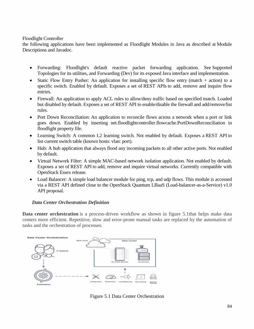
84
Floodlight Controller
the following applications have been implemented as Floodlight Modules in Java as described at Module
Descriptions and Javadoc.
Forwarding: Floodlight's default reactive packet forwarding application. See Supported
Topologies for its utilities, and Forwarding (Dev) for its exposed Java interface and implementation.
Static Flow Entry Pusher: An application for installing specific flow entry (match + action) to a
specific switch. Enabled by default. Exposes a set of REST APIs to add, remove and inquire flow
entries.
Firewall: An application to apply ACL rules to allow/deny traffic based on specified match. Loaded
but disabled by default. Exposes a set of REST API to enable/disable the firewall and add/remove/list
rules.
Port Down Reconciliation: An application to reconcile flows across a network when a port or link
goes down. Enabled by inserting net.floodlightcontroller.flowcache.PortDownReconciliation in
floodlight property file.
Learning Switch: A common L2 learning switch. Not enabled by default. Exposes a REST API to
list current switch table (known hosts: vlan: port).
Hub: A hub application that always flood any incoming packets to all other active ports. Not enabled
by default.
Virtual Network Filter: A simple MAC-based network isolation application. Not enabled by default.
Exposes a set of REST API to add, remove and inquire virtual networks. Currently compatible with
OpenStack Essex release.
Load Balancer: A simple load balancer module for ping, tcp, and udp flows. This module is accessed
via a REST API defined close to the OpenStack Quantum LBaaS (Load-balancer-as-a-Service) v1.0
API proposal.
Data Center Orchestration Definition
Data center orchestration is a process-driven workflow as shown in figure 5.1that helps make data
centers more efficient. Repetitive, slow and error-prone manual tasks are replaced by the automation of
tasks and the orchestration of processes.
Figure 5.1 Data Center Orchestration

85
What is Data Center Orchestration?
Data center orchestration software uses the automation of tasks to implement processes, such as
deploying new servers. Automation solutions which orchestrate data center operations enable an agile
DevOps approach for continual improvements to applications running in the data center.
Consider instruments or singers in a band. Each has an independent sound, just as software defined
applications have their own task. But when they work well together, a unique sound is produced.
Orchestration outlines how individual tasks can come together for a larger purpose. It organizes all the
tasks of various services and creates a highly functioning and responsive data center.
The massive amount of data move to cloud computing has put more pressure on the data center. Data
center needs to be a central management platform and be able to provide the same agility as public
clouds. Data center automation and orchestration creates the efficiencies needed to meet that demand.
What is the Function of Data Center Orchestration Systems?
Data center orchestration systems automate the configuration of L2-L7 network services, compute and
storage for physical, virtual and hybrid networks. New applications can be quickly deployed.
Benefits of data center orchestration systems include:
Streamlined provisioning of private and public cloud resources.
Less time to value between a business need and when the infrastructure can meet the need.
Less time for IT department to deliver a domain specific environment.
Data center orchestration systems are a framework for managing data exchanged between a business
process and application. They use the following functions:
o Scheduling and coordination of data services.
o Leveraging of distributed data repository for large data sets.
o Tracking and publishing APIs for automatic updates of metadata management.
o Updating policy enforcement and providing alerts for corrupted data.
o Integrating data services with cloud services.
Data Center Orchestration Tools
The following are popular data center orchestration and automation tools for the data center and cloud
environments:
86
Ansible — An agentless configuration management tool. Created to push changes
and re-configure newly deployed machines. Has an ecosystem conducive for
writing custom apps. The platform is written in Python and allows users to script
commands in YAML.
Chef — Uses a client-server architecture and is based on Ruby. Presents the
infrastructure as a code.
Docker — Features isolated containers, which allows the execution of many
applications on one server.
Puppet — Built with Ruby and uses an agent/master architecture. Created to
automate tasks for system administrators.
Vagrant — Helps build, configure and manage lightweight virtual machine
environments. Lets every member of the IT team have identical development
environments.
Does Avi offer Data Center Orchestration?
Yes. Avi provides centrally orchestrated microservices composed of a fabric of proxy services with
dynamic load balancing, service discovery, security, micro-segmentation, and analytics for container-
based applications running in OpenShift and Kubernetes environments. Avi Networks delivers scalable,
enterprise-class microservices and containers to deploy and manage business-critical workloads in
production environments using Redhat container orchestration with OpenShift and Kubernetes clusters.
Kubernetes (also known as K8s) is open source software for deploying, scaling and managing
containerized applications. As an orchestrator, Kubernetes handles the work of scheduling containers on
a cluster and also manages the workloads to ensure they run as you intended.
Benefits: Why Use Kubernetes?
As the first Cloud Native Cloud Foundation (CNCF) project, Kubernetes is the fastest growing
project in the history of Open Source software. K8s became popular for the following key reasons:
Portability
Kubernetes offers portability, and faster, simpler deployment times. This means that companies can
take advantage of multiple cloud providers if needed and can grow rapidly without having to re -
architect their infrastructure.
Scalability
With Kubernetes' ability to run containers on one or more public cloud environments, in virtual
machines, or on bare metal means that it can be deployed almost anywhere. And because
Kubernetes has fundamentally changed the way development and deployments are made, teams can
also scale much faster than they could in the past.

87
High Availability
Kubernetes addresses high availability at both the application and the infrastructure level. Adding a
reliable storage layer to Kubernetes ensures that stateful workloads are highly available. In addition
to this, the master components of a cluster can be configured for multi -node replication (multi-
master) and this also ensures a higher availability.
Open Source
Since Kubernetes is open source, you can take advantage of the vast ecosystem of other open source
tools designed specifically to work with Kubernetes without the lock-in of a closed/proprietary
system.
Proven, and Battle Tested
A huge ecosystem of developers and tools with 5,608 GitHub repositories and counting means that
you won‘t be forging ahead into new territory without help.
Kubernetes 101 Architecture
The way Kubernetes is architected is what makes it powerful. Kubernetes has a basic client and
server architecture, but it goes way beyond that. Kubernetes has the ability to do rolling updates, it
also adapts to additional workloads by auto scaling nodes if it needs to and it can also self-heal in
the case of a pod meltdown. These innate abilities provide developers and operations teams with a
huge advantage in that your applications will have little to no down time. In the figure 5.3, a brief
overview of the master and its worker nodes with a high level overview of how Kubernetes manages
workloads is shown.
Figure 5.3 Kubernetes architecture
Kubernetes Master
The Kubernetes master is the primary control unit for the cluster. The master is responsible for
managing and scheduling the workloads in addition to the networking and communicat ions across
the entire cluster.
These are the components that run on the master:
Etcd Storage – An open-source key-value data store that can be accessed by all nodes in the cluster.

88
It stores configuration data of the cluster‘s state.
Kube-API-Server – The API server manages requests from the worker nodes, and it receives REST
requests for modifications, and serves as a front-end to control cluster.
Kube-scheduler – Schedules the pods on nodes based on resource utilization and also decides
where services are deployed.
Kube-controller-manager – It runs a number of distinct controller processes in the background to
regulate the shared state of the cluster and perform routine tasks. When there is a change to a
service, the controller recognizes the change and initiates an update to bring the cluster up to the
desired state.
Worker Nodes
These nodes run the workloads according the schedule provided by the master. The interaction
between the master and worker nodes are what‘s known as the control plane.
Kubelet – Kubelet ensures that all containers in the node are running and are in a healthy state. If a
node fails, a replication controller observes this change and launches pods on another healthy pod.
Integrated into the kubelet binary is ‗cAdvisor` that auto-discovers all containers and collects CPU,
memory, file system, and network usage statistics and also provides machine usage stats by
analyzing the ‗root‘ container.
Kube Proxy – Acts as a network proxy and a load balancer. Additionally, it forwards the request to
the correct pods across isolated networks in a cluster.
Pods - A pod is the basic building block on Kubernetes. It represents the workloads that get
deployed. Pods are generally collections of related containers, but a pod may also only have one
container. A pod shares network/storage and also a specification for how to run the containers.
Containers – Containers are the lowest level of microservice. These are placed inside of the pods
and need external IP addresses to view any outside processes.
Use Cases for Bandwidth Scheduling, Manipulation, and Calendaring
Bandwidth calendaring is a category of use cases[182
] that (at their heart) embody the concept of time-
based bandwidth manipulation. In these cases, the manipulation refers to the addition, deletion, or
modification of bandwidth in the network. The reasons, or triggers, that would cause one to perform
bandwidth manipulation vary widely but include modification of bandwidth characteristics to more
closely match traffic patterns, service demands and disruptions, or operational planning for future
changes such as capacity. The common theme here is that these generally involve some sort of temporal
cycle. In fact, not only is the bandwidth manipulated on some sort of timed schedule, but the causes for
manipulating bandwidth are usually motivated by a need to do so based on some sort of schedule that
otherwise would be (or is) performed manually. Let‘s explore.

89
And let‘s start simply. Figure 5.3 demonstrates a scenario where a service provider owns two data
centers that are interconnected by some network links. One is located in Sunnyvale, California, and the
other in Portsmouth, New Hampshire.
Figure 5.3 Data center interconnection example
The data centers are purposely geographically diverse to facilitate a lower-latency user experience and
also to handle disaster recovery scenarios.


