School of Mechanical and Industrial Engineering Mechanics of Machinery Group Assignment-Universal Joints Group Members 1. Gezaie Abera 2. Girma Atenaw 3. Hailemichael Atkilt 4. Nathnael Bekele 5. Redwan Adem 6. Sagni Mulugeta 7. Shumet Derebe 8. Sitotaw Mengistie December, 2012.
Transcript
School of Mechanical and Industrial
Engineering
Mechanics of Machinery
Group Assignment-Universal Joints
Group Members
1. Gezaie Abera
2. Girma Atenaw
3. Hailemichael Atkilt
4. Nathnael Bekele
5. Redwan Adem
6. Sagni Mulugeta
7. Shumet Derebe
8. Sitotaw Mengistie
December, 2012.
Table Of Contents
Page
1. Introduction 1
2. Types of U-joints 2
3. Velocity ratio of shafts 4
4. Polar angular velocity diagram 6
5. Coefficient of speed fluctuation 6
6. Angular acceleration of driven shafts 7
7. Double Hooke’s joint 8
8. Applications 9
9. Appendix 12
10. Bibliography 14
Mechanics of Machinery Universal Joints
Group Assignment 1
UNIVERSAL JOINTS
1. Introduction
A u-joint (universal joint) is basically a flexible pivot point that transmits power through rotational motion between two shafts not in a straight line.i It is a connection between two intersecting rotating shafts which are coplanar and are inclined at an angle with respect to each other.ii In other words, a universal joint is a positive, mechanical connection between rotating shafts, which are usually not parallel, but intersecting. They are used to transmit motion, power, or both. U-joints are used to absorb vibrations and shock in the drive line; they are also used to allow the rear/front to travel up and down. Universal joints go by a lot of different names - U joint, Cardan or Hooke's joint - and are used to make a bent joint that can move in any direction. The most common use is shafts that work in a rotary motion.
The angle between the shafts may vary during the operation.iii
Currently, several mechanical, pneumatic, hydraulic and magnetic mechanisms are used to transmit power between two intersecting shafts; however, the mechanical type (universal joint) is mostly used in industry due to its low cost.iv
The u-joint needs to be flexible to compensate for changes in driveline angle due to the constantly changing terrain under the vehicle.
History The original Universal joint was developed in the sixteenth century by a French mathematician named Cardan. In the seventeenth century, Robert Hooke developed a cross-type Universal joint, based on the Cardan design. Then in 1902, Clarence Spicer modified Cardan and Hooke’s inventions for the purpose of transmitting engine torque to an automobile’s rear wheels. By joining two shafts with Y-shaped forks to a pivoting cruciform member, the problem of torque transfer through a connection that also needed to compensate for slight angular variations was eliminated. Both names, Spicer and Hooke, are at times used to describe a Cardan U-joint.
The u-joint is considered to be one of the oldest of all flexible couplings. It is commonly known for its use on automobiles and trucks. A universal joint in its simplest form consists of two shaft yokes at right angles to each other and a four point cross which connects the yokes. The cross rides inside the bearing cap assemblies, which are pressed into the yoke eyes. One of the problems inherent in the design of a u-joint is that the angular velocities of the components vary over a single rotation.v
Mechanics of Machinery Universal Joints
Group Assignment 2
Universal joints are available in steel or in thermoplastic body members. Universal joints made of steel have maximum load-carrying capacity for a given size.
Standard u-joints aren't designed to run at extreme driveshaft angles unless they are specially constructed. As a rule of thumb, the angle of a driveshaft should not exceed 22 degrees. However, some manufacturers do make quality high-angle drives shafts that operate dependably from 22 to 80 degrees. Extreme-angle drive shafts are achieved by using a double cardan constant velocity joint. This is basically a joint with two u-joints.vi
2. Types of U-joints 1. Depending upon the number of joint:
• Single Joint
Single joint is one of the most basic types of universal joints. In this type, two rigid shafts are made to connect using a cross-shaped bar known as spider. There is also a U-shaped device known as yoke which is connected to the end of each shaft. The ends of each yoke are further attached to the two ends of the spider.
• Double Joint
A double joint is a combination of two single universal joints between two rigid shafts which allows increased degree of motion between the two ends. A double joint is flexible up to 90 degrees which is double than the ordinary basic joint.
2. Depending upon the Velocity Ratio:
• Variable Velocity Joint
In this type of joint, driving and driven shaft is placed in a straight line so that they may turn at the same speed. In vehicle, driving and driven shaft is inclined at an angle. The average speed of the driven shaft is half than that of the driving shaft. When the universal joint angle is increased, the speed variation in the driven shaft also increases.
• Constant Velocity Joint
Constant velocity joint (CV joint) allows the drive shaft to transmit power at any angle without the loss of speed. Generally, CV joint can be used in front wheel drive or all wheel drive vehicle.
The simplest and most common type is called the Cardan joint or Hooke joint. It is shown in Figure 1. It consists of two yokes, one on each shaft, connected by a cross-
Mechanics of Machinery Universal Joints
Group Assignment 3
shaped intermediate member called the spider. The angle between the two shafts is called the operating angle. It Is generally, but n01 necessarily, constant during operation. Good design practice calls for low operating angles, often less than 25°, depending on the application. Independent of this guide line, mechanical interference In the construction of Cardan joints limits the operating angle to a maximum (often about 37½°), depending on its proportions.
(a) (b)
Figure 2: (a) Single U-joint and (b) Double U-joint
Single Cardan Jointsvii Advantages Disadvantages
Low side thrust on bearings Velocity and acceleration fluctuation increases with operating angle
Large angular displacements are possible Lubrication is required to reduce wear High torsional stiffness Shafts must lie in precisely the same plane High torque capacity Backlash difficult to control
Mechanics of Machinery Universal Joints
Group Assignment 4
3. Velocity ratio of shafts
Consider two shafts A and B which are the driver and follower, respectively. The axes of the two shafts are inclined at an angle δ from the plan view. If observed from the direction of A when the shafts rotate, A-A traces a circle while B-B traces an ellipse. The ellipse is a projection of the circle trace by b-b. viii
If the shaft A turns through an angle of θ from AA to A1A1, then the projection of BB
will also turn through angle θ to B1B1. During this time the angle turned by shaft B is β as observed from the axis of shaft B. The projections of B1 and B2 are AA and C1 and C2.
Form the geometry of the projections,
tan θ=OC1/C1B1
and
tan β=OC2/C2B2=OC1/C1B1
Combining these two equations, we get
tan θ/ tan β= OC1/ OC2 =OC1/OB1
Mechanics of Machinery Universal Joints
Group Assignment 5
From the plan view, it can be observed that
OC1/OB1=cosδ
Thus, the relationship betweenθ, the angular displacement of shafts A and B, the angular displacement of shaft B is obtained to be
tan θ= tan β*cosδ
Differentiating the equation with respect to time, the output shaft velocity can be related to the input shaft velocity.
Sec2dθ/dt=sec2dβ/dt*cosδ
where δ is a constant.
dθ/dt=ωA
and
dβ/dt=ωB
The velocity relationship between the velocities of the two shafts is thus obtained to be
ωAsec2θ=ωBsec2β*cosδ
From the trigonometric relations,
Sec2β=1 + tan2β
Substituting for tanβ in equation 7.5,
Sec2β= 1 + tan2θ/cos2δ=(cos2δ+tan2θ)/cos2δ
Therefore, from equation 7.9 we obtain and equation relating the input and output velocities
Upon simplification, the velocity relation is obtained to be
ωA=[(1-sin2δ*cos2θ*ωB)/cosδ]
Hence, the ratio of the angular velocities is given by
ωB/ωA=[(cosδ)/(1-sin2δ*cos2θ)]
Mechanics of Machinery Universal Joints
Group Assignment 6
The ratio ωB/ωA has a maximum value when cosθ ≅ ±1, for which θ=0 or θ=180o or any multiple of 180o. For this condition,
(ωB/ωA)max= [(cosδ)/(1-sin2δ)]=(1/cosδ)
The ratio ωB/ωA has a minimum value when cos θ=0, for which θ=90o or θ=270o. For this condition,
(ωB/ωA)min=cosδ
4. Polar Angular Velocity Diagram
The velocity of the driver and follower for a complete revolution of the joint is shown on a polar angular velocity diagram. Since the angular velocity of the driver is assumed constant, it is represented by a circle. The angular velocity of the follower is shown as an ellipse, since its magnitude varies between a maximum and a minimum. The ellipse crosses the circle at four points, in which case, during a cycle the angular velocities of the driver and the driven shaft are equal. For this condition,
cosδ/(1-sin2δ*cos2θ)=1
cos2θ=(1-cosδ)/sin2δ=1/(1+ cosδ)
Upon simplification, we obtain
Sec2θ=1+ cosδ=1+tan2θ
Solving for tanθ, we get
tanθ=±√ cosδ
5. Coefficient of Speed fluctuation
The difference between the maximum and minimum speeds of the follower expressed as a ration of the driving shaft speed for constant angle δ between the axes of the driving and driven shafts is defined as the coefficient of speed fluctuation.
q= [((ωB)max-(ωB)min)/ ωA]
Substitution for (ωB)max and (ωB)min yields
q= [((1/cosδ)(ωA)-cosδ(ωA))/ ωA]
OR
Mechanics of Machinery Universal Joints
Group Assignment 7
q= [(1/cosδ)-cosδ]
From the equation 7.21 the coefficient of speed fluctuation is obtained to be
q= sinδ*tanδ
For small angle δ, sinδ=δ and tanδ=δ. Hence, the coefficient of speed fluctuation is given by
q=δ2
where δ is in radians.
Having obtained the coefficient of speed fluctuation q, the total fluctuation of the speed is then given by
Total fluctuation of speed = δ2*ωA
6. Angular Acceleration of driven shaft
Assuming ωA to be constant, for a constant inclination δ between the driver and follower, the angular velocity of the follower is
ωB =[( cosδ)/(1-sin2δ*cos2θ*ωA)]ωA,
which is observed to depend on the angular position θ. The angular acceleration of the driven shaft is then obtained by differentiating the angular speed of the driven shaft.
αB=-ωA2*(cosδ*sin2δ*sin2θ/(1-sin2δ*cos2θ)2)
For the maximum angular acceleration, the acceleration term is differentiated with respect to time and set equal to zero to give the position for which the acceleration is maximum or minimum i.e.,
Thus, having obtained the angular position for which the angular acceleration is maximum, the angular acceleration is obtained by substituting for θ in the equation of the acceleration.
7. Double Hooke’s joint
In an automobile, if only a single Hooke’s joint were used, either the speed of the engine or that of the car would have to vary during each revolution of the drive shaft. However, the inertia at both ends would resist this occurrence as a result of which high stresses would occur on the transmission shaft and slippage on the tires. This problem is solved by employing a double Hooke’s joint which provides a uniform velocity between input and output ends, limiting the variation of speed to the intermediate shaft.
If the driver and follower are inclined equally relative to the intermediate shaft, the fluctuation of speed will be confined to the intermediate shaft alone. The intermediate shaft can then be made short and light in order to reduce the inertia in the transmission.
Figure 3.
For double Hooke’s joint in which the forks are the same plane, the relation between
ω2, speed of the driver, and ω4, speed of the follower, is obtained as follows. For angle
θ which the driver turns through in a given time,
tan θ=tan γ*cosδ
where β is the angle turned by the follower or the output shaft. From these relations, we have
tan θ=tan β
OR
Mechanics of Machinery Universal Joints
Group Assignment 9
θ=β,
i.e. the driving and driven shafts turn through the same angle in the same plane.
Therefore,
ω4=ω2
If the forks on the intermediate shaft are set ate right angle, the speed of the follower ω4
will fluctuate between ω2*cos2δ and ω2*(1/cos2δ).
8. Applications
U-joints are used in a variety of applications, wherever handling significant angular misalignment is the main focus. Typical applications include: articulating mechanisms, food processing equipment, replacement for expensive gearboxes, and drives where motor position must be moved angularly off centerline of the driven unit.ix
Typical applications of universal joints include aircraft, appliances, control mechanisms, electronics, Instrumentation, medical and optical devices, ordnance, radio, sewing machines, textile machinery and tool drives.
Universal joints with thermoplastic body members are used in light industrial applications in which their self-lubricating feature, light weight, negligible backlash, corrosion resistance and capability for high-speed operation are significant advantages. Universal joints of special construction, such as ball-jointed universals are also available. These are used for high-speed operation and for carrying large torques. They are available both in miniature and standard sizes.
Mechanics of Machinery Universal Joints
Group Assignment 10
Figure 4
Mechanics of Machinery Universal Joints
Group Assignment 11
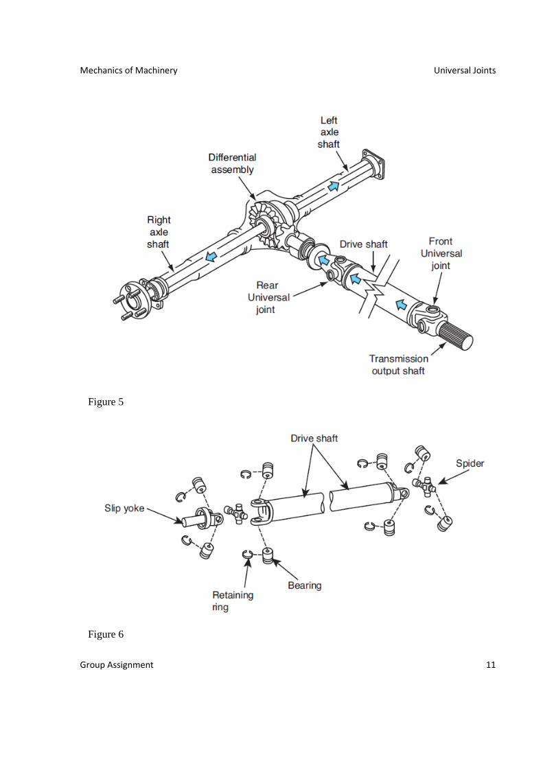
Figure 5
Figure 6
Mechanics of Machinery Universal Joints
Group Assignment 12
9. Appendix
Mechanics of Machinery Universal Joints
Group Assignment 13
TABLE 1 - The Effect of Shaft Angle (ß) on Single U niversal Joint Performance For Constant Input Speed*
Mechanics of Machinery Universal Joints
Group Assignment 14
10. Bibliography
i Jim Oaks, TRS Magazine, Summer 2008.
ii Alem Bazezew, Mechanisms of Machinery, Department of Mechanical Engineering, Faculty of
Technology, Addis Ababa University, July 2001.
iii Alem Bazezew, Mechanisms of Machinery, Department of Mechanical Engineering, Faculty of
Technology, Addis Ababa University, July 2001.
iv Majid Yaghoubi, Ali Jafary, Seyed Saeid Mohtasebi, Design, simulation and evaluation of a new universal
joint with intersecting angle upto 100 degrees for farm machineries, Australian Journal of Agricultural
Engineering.
v Jim Oaks, TRS Magazine, Summer 2008.
vi Jim Oaks, TRS Magazine, Summer 2008.
vii Couplings and Universal Joints, www.sdp-si.com/
viii Alem Bazezew, Mechanisms of Machinery, Department of Mechanical Engineering, Faculty of
Technology, Addis Ababa University, July 2001.
ix U-Joint Overview, Internet
Note: All calculations were taken from Alem Bazezew, Mechanisms of Machinery, Department of
Mechanical Engineering, Faculty of Technology, Addis Ababa University, July 2001.