+ All Categories
Home > Documents > School of Microelectronics Shanghai Jiao Tong University ...

School of Microelectronics Shanghai Jiao Tong University ...

Date post: 10-Dec-2021
Category:
Upload: others
View: 2 times
Download: 0 times
Share this document with a friend
58
2010-9-6 Slide 1 Introduction to Design Automation Introduction to Design Automation Lecture 1. Lecture 1. Course Overview Course Overview Guoyong Shi, PhD [email protected] School of Microelectronics Shanghai Jiao Tong University September, 2010
Transcript

2010-9-6 Slide 1

Introduction to Design AutomationIntroduction to Design Automation

Lecture 1. Lecture 1. Course OverviewCourse Overview

Guoyong Shi, [email protected]

School of MicroelectronicsShanghai Jiao Tong University

September, 2010

2010-9-6 Lecture 1 slide 2

OutlineOutline• Course overview• CAD basics• Project-based learning and teamwork• What is EDA?• Top 10 algorithms in 20th century

2010-9-6 Lecture 1 slide 3

What to learn in this course?What to learn in this course?• Learn software skills for Design Automation• Get familiar with Linus OS or CYGWIN• Learn GUI programming toolkits

– GTK, Qt, or others• Learn compiler tools

– Yacc and Bison– PCCTS

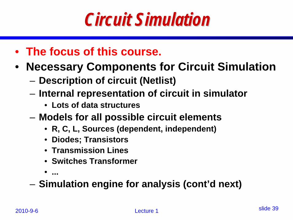
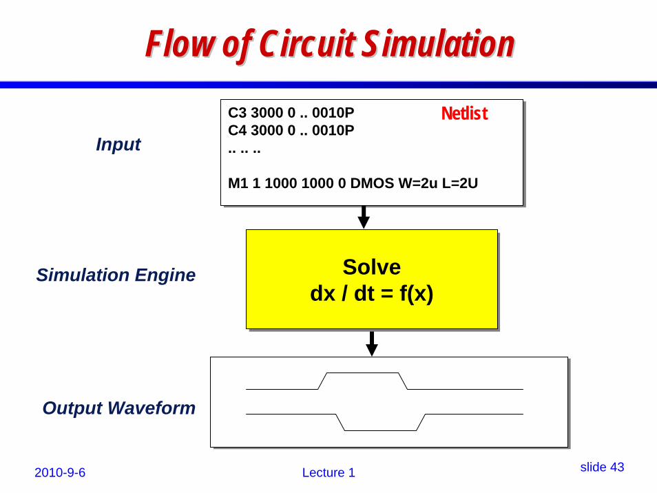
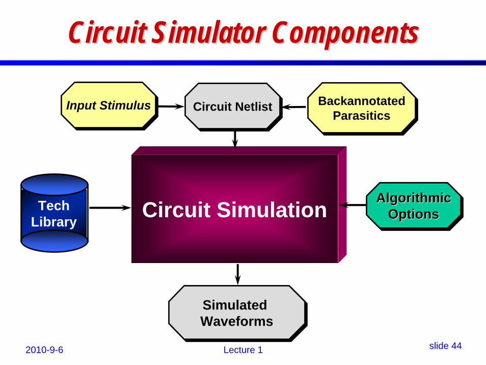
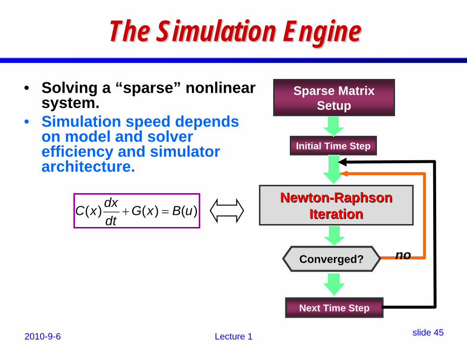
• Learn principles of circuit simulation– to construction methods and sovling algorithms

2010-9-6 Lecture 1 slide 4

ComputerComputer--Aided Design (CAD)Aided Design (CAD)

2010-9-6 Lecture 1 slide 5

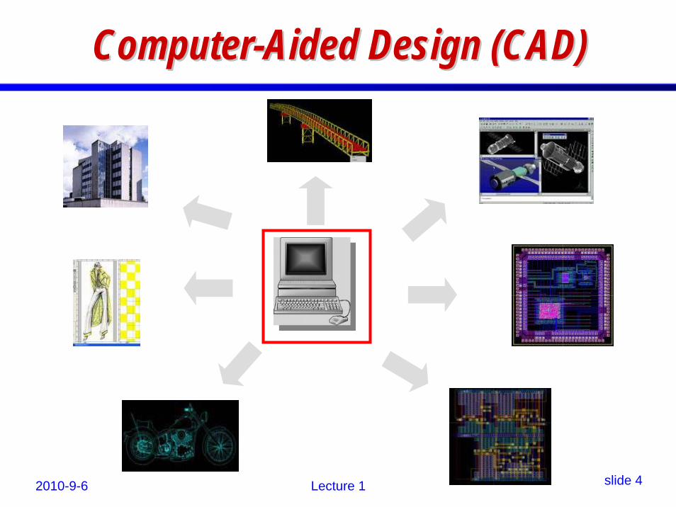
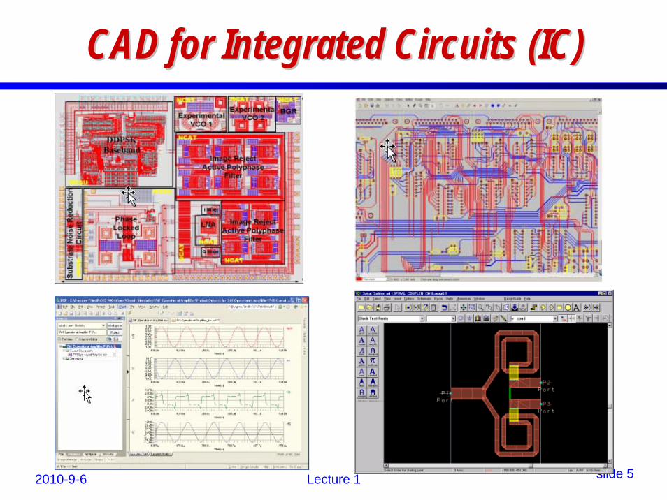
CAD for Integrated Circuits (IC)CAD for Integrated Circuits (IC)

2010-9-6 Lecture 1 slide 6

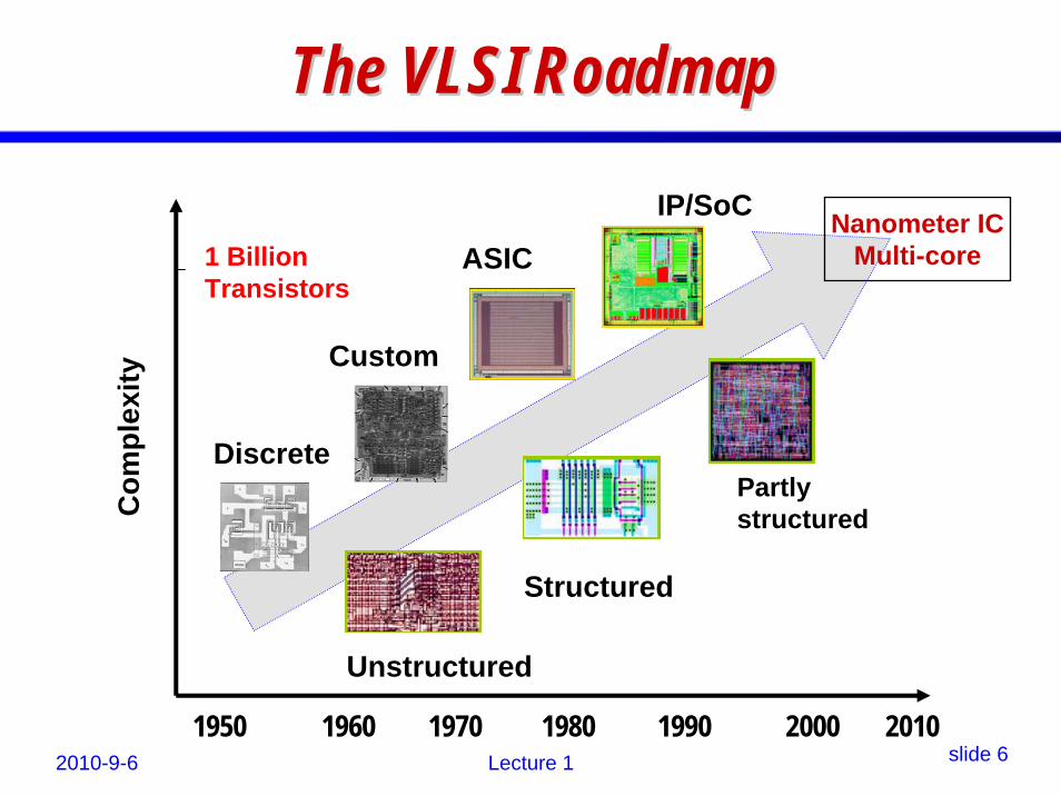
The VLSI RoadmapThe VLSI RoadmapC

ompl

exity

1 Billion Transistors

Discrete

Custom

ASIC

Unstructured

Structured

Partly structured

IP/SoC

1950 1960 1970 1980 1990 2000 2010

Nanometer ICMulti-core

2010-9-6 Lecture 1 slide 7

EDA = VLSI CADEDA = VLSI CAD• EDA = Electronic Design Automation• EDA is another name for Computer-Aided

Integrated Circuit Design

• EDA as an area born with the IC industry.• EDA is application science and technology.• EDA is part of the software industry

2010-9-6 Lecture 1 slide 8

What this course is and is notWhat this course is and is not• This course does not teach how to use EDA

tools – you learn them in IC design courses

• This course teaches the basic principles onhow to develop EDA software.– You mainly learn how a SPICE simulator is

developed.

2010-9-6 Lecture 1 slide 9

Who should learn this courseWho should learn this courseThose who are interested in• challenging software programming.• circuit simulation.• analog/RF circuit design.• a career in EDA industry

2010-9-6 Lecture 1 slide 10

Textbook & WebpageTextbook & Webpage• Textbook

– No official textbook is used– You must come to attend all lectures!

• Course webpage– http://edalab.sjtu.edu.cn/moodle/– 集成电路设计/EDA引论

– password: ugradeda

– For downloading course materials– For uploading finished homework, etc.

2010-9-6 Lecture 1 slide 11

Good Reference BooksGood Reference Books1. T.L. Pillage, R.A. Rohrer, C. Visweswariah,

Electronic Circuit and System Simulation Methods, McGraw-Hill, Inc., 1995.

2. C.K. Cheng, J. Lillis, S. Lin and N. Chang, Interconnect Analysis and Synthesis, John Wiley & Sons, Inc., 2000.

... but are not required.

2010-9-6 Lecture 1 slide 12

Instructor & TAInstructor & TA• Instructor

– 施国勇 教授

[email protected]

• TA: 徐辉 (master student)– [email protected]

2010-9-6 Lecture 1 slide 13

Instructor Office HoursInstructor Office Hours

• Tuesday: 1:00-2:00pm• Thursday: 1:00-2:00pm• Or appointment by email

• Office: School Building, Room 415

• TA office hours will be posted on the course webpage

2010-9-6 Lecture 1 slide 14

Course Structure & GradingCourse Structure & Grading• 3 hours x 17 weeks = 51 hours• Lectures + Projects + HW + Final Exam

• Grading policy (for reference)– (30%) Lecture-based assignments (HW);– (40%) A Spice simulator (team work)

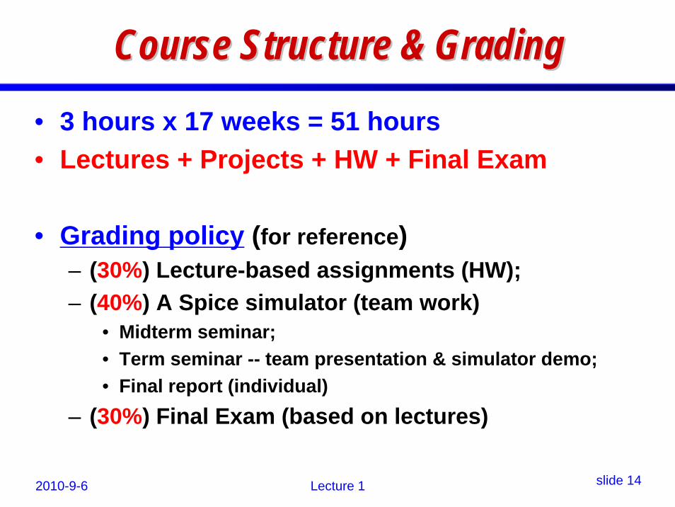
• Midterm seminar;• Term seminar -- team presentation & simulator demo;• Final report (individual)

– (30%) Final Exam (based on lectures)

2010-9-6 Lecture 1 slide 15

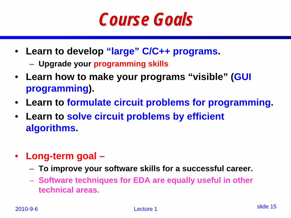
Course GoalsCourse Goals• Learn to develop “large” C/C++ programs.

– Upgrade your programming skills• Learn how to make your programs “visible” (GUI

programming).• Learn to formulate circuit problems for programming.• Learn to solve circuit problems by efficient

algorithms.

• Long-term goal –– To improve your software skills for a successful career. – Software techniques for EDA are equally useful in other

technical areas.

2010-9-6 Lecture 1 slide 16

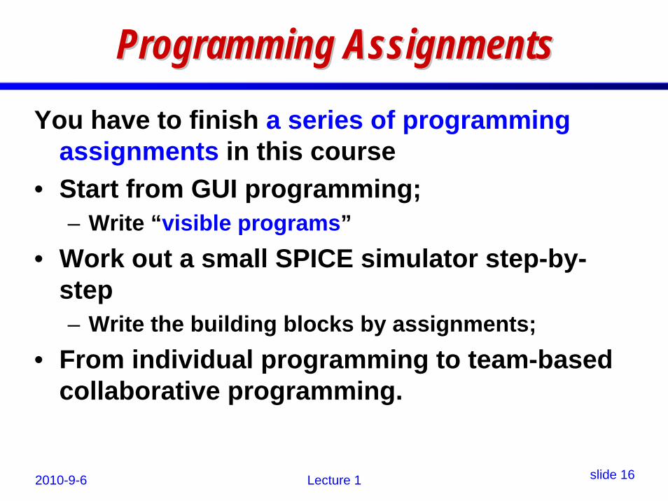
Programming AssignmentsProgramming AssignmentsYou have to finish a series of programming

assignments in this course• Start from GUI programming;

– Write “visible programs”• Work out a small SPICE simulator step-by-

step– Write the building blocks by assignments;

• From individual programming to team-based collaborative programming.

2010-9-6 Lecture 1 slide 17

ProjectProject--based Learningbased Learning• Emphasized in this course!• The project components:

– Develop a GUI for your simulator – Develop a mini-SPICE simulator capable of

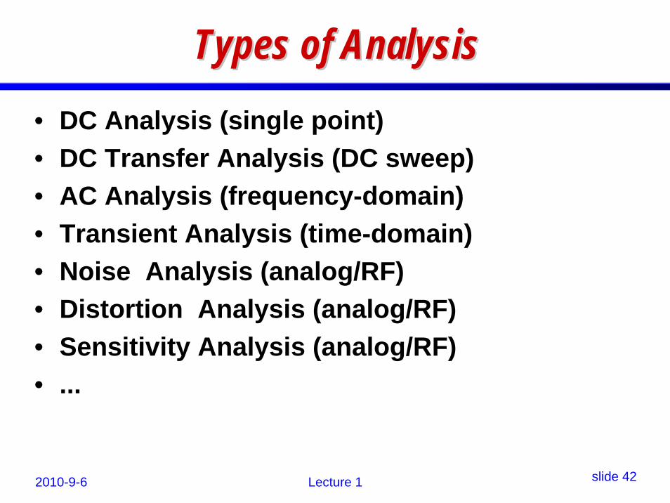
simulating• R, C, L, Controlled Sources, (Diodes, MOSFETs)• DC analysis; AC analysis; Transient analysis; Error

control; ...

• Teamwork – About 4 students in each team

• Learn to present your work well– Every student must present at least once

2010-9-6 Lecture 1 slide 18

Student Achievements Last YearStudent Achievements Last Year

Students of year 2009• The best simulators could simulate diodes,

MOS transistors;• could do DC, AC + Noise, Transient analysis,

and error control.– much better than the students of the year 2008.

• Reason:– The class-scale was reduced (about 20 students)

2010-9-6 Lecture 1 slide 19

TeamworkTeamwork• Teamwork is emphasized in this course.• Teams are set up in the first two weeks.• Each team elects a team leader.• The team leaders should

– Coordinate job assignments inside team– Monitor project progress– Encourage innovative implementations– Regulate team member presentations

• Every student should present at least once

2010-9-6 Lecture 1 slide 20

How to form teams?How to form teams?• Num of teams depending on registration

– 4 members in each team (recommended) • Rough work-load divisions:

– One for GUI– One for Parser– One for Solver– One for Analysis Tasks (DC/AC/Tran)

• Teams are not advised to change thru out the course.

• Teams are encouraged to compete by presentations and demos!

2010-9-6 Lecture 1 slide 21

Final Term ReportFinal Term Report

• Every student should submit an individual final project report.– Should emphasize your own work in the team– Should include:

• implementation details; • explanation of the code design; and • experimental results.

– Attach the source code.

• Learn to write your final report like a technical paper.

2010-9-6 Lecture 1 slide 22

Your Individual GradeYour Individual Grade

• The final grade of each student will be based upon1. Weekly assignments (have to turn in before due

and get graded)2. The overall team performance3. Your individual contribution (seen from

presentation, demo, and report)4. The final exam (everyone must take)

2010-9-6 Lecture 1 slide 23

Target of the Class ProjectTarget of the Class Project• Develop a small circuit simulator

– with GUI (for netlist input & waveform output)– with Netlist parser– with linear solver (for solving circuits)– capable of simulating basic circuit elements;

including transistors– capable of DC/AC/Tran analyses and error control,

etc.

2010-9-6 Lecture 1 slide 24

Assignments PolicyAssignments Policy• All assignments are due in one week

(exceptions will be noted) – Turn in no later than a week after the assignment

lecture is finished.• Submit all finished assignment electronically

to MOODLE.• Without permission, no late turn-in will be

graded.– So, be aware of the due!

2010-9-6 Lecture 1 slide 25

Academic IntegrityAcademic Integrity• No tolerance to cheating!• Any cheating in exams will lead to a Fail

grade.• Typical cheating behavior:

– copy other student’s assignments;– copy other student’s code;– use earlier-year student’s work;– cheating in exams.

• Students are encouraged to exchange ideas.

2010-9-6 Lecture 1 slide 26

A Brief IntroductionA Brief Introductionto EDAto EDA

2010-9-6 Lecture 1 slide 27

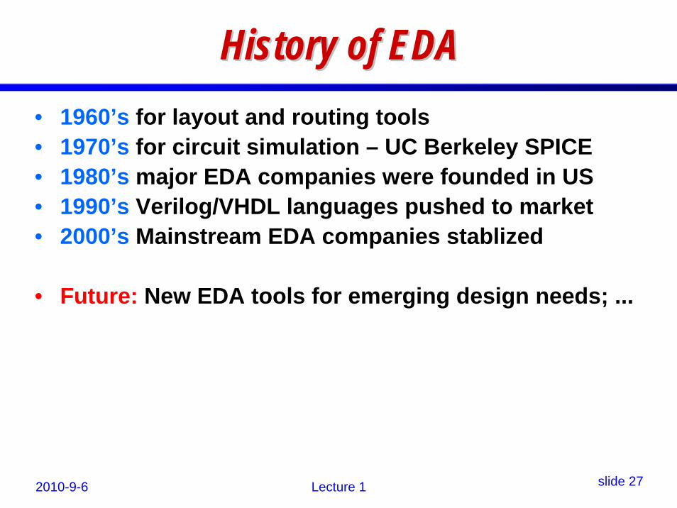
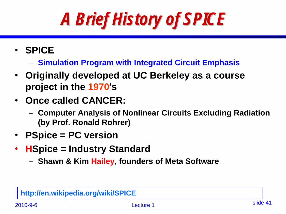
History of EDAHistory of EDA• 1960’s for layout and routing tools• 1970’s for circuit simulation – UC Berkeley SPICE• 1980’s major EDA companies were founded in US• 1990’s Verilog/VHDL languages pushed to market• 2000’s Mainstream EDA companies stablized

• Future: New EDA tools for emerging design needs; ...

2010-9-6 Lecture 1 slide 28

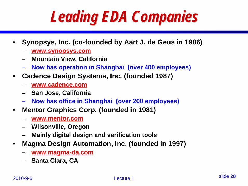
Leading EDA CompaniesLeading EDA Companies• Synopsys, Inc. (co-founded by Aart J. de Geus in 1986)

– www.synopsys.com– Mountain View, California– Now has operation in Shanghai (over 400 employees)

• Cadence Design Systems, Inc. (founded 1987)– www.cadence.com– San Jose, California– Now has office in Shanghai (over 200 employees)

• Mentor Graphics Corp. (founded in 1981)– www.mentor.com– Wilsonville, Oregon– Mainly digital design and verification tools

• Magma Design Automation, Inc. (founded in 1997)– www.magma-da.com– Santa Clara, CA

2010-9-6 Lecture 1 slide 29

Leading EDA Companies (contLeading EDA Companies (cont’’d)d)• Ansoft Corporation

– founded by Dr. Zoltan Cendes in 1984– www.ansoft.com– Pittsburgh, Pennsylvania (PA)– mainly on EM/RF design tools

• Taiwan SpringSoft (growing quickly)– www.springsoft.com

2010-9-6 Lecture 1 slide 30

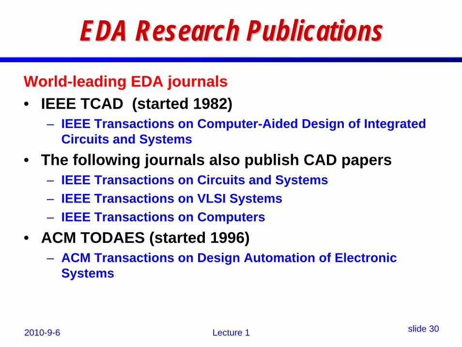
EDA Research PublicationsEDA Research PublicationsWorld-leading EDA journals• IEEE TCAD (started 1982)

– IEEE Transactions on Computer-Aided Design of Integrated Circuits and Systems

• The following journals also publish CAD papers– IEEE Transactions on Circuits and Systems– IEEE Transactions on VLSI Systems– IEEE Transactions on Computers

• ACM TODAES (started 1996)– ACM Transactions on Design Automation of Electronic

Systems

2010-9-6 Lecture 1 slide 31

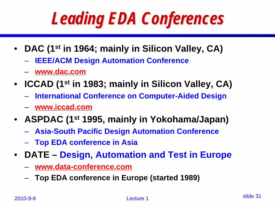
Leading EDA ConferencesLeading EDA Conferences• DAC (1st in 1964; mainly in Silicon Valley, CA)

– IEEE/ACM Design Automation Conference– www.dac.com

• ICCAD (1st in 1983; mainly in Silicon Valley, CA)– International Conference on Computer-Aided Design– www.iccad.com

• ASPDAC (1st 1995, mainly in Yokohama/Japan)– Asia-South Pacific Design Automation Conference– Top EDA conference in Asia

• DATE – Design, Automation and Test in Europe– www.data-conference.com– Top EDA conference in Europe (started 1989)

2010-9-6 Lecture 1 slide 32

International EDA OrganizationsInternational EDA Organizations• CEDA – Council on Electronic Design Automation

– An organization of IEEE formed in 2005– To unify EDA-related IEEE activities among

• Antennas and Propagation Society• Circuits and Systems Society• Computer Society• Electron Devices Society• Solid State Circuits Society

• The EDA Consortium– The trade association for electronic design companies– www.edac.org

• The European Design and Automation Association

2010-9-6 Lecture 1 slide 33

EDA is a comprehensive areaEDA is a comprehensive area• EDA is “interdisciplinary”

– Using knowledge from many technical areas• EDA is important in that the whole IC industry

relies on it!– From device to manufacturing to circuit design– to verification, ...

• EDA is comprehensive in the sense of – Knowledge; Research; Industry revenue;– Investment and global competition

• US universities and companies lead the whole EDA technology.

2010-9-6 Lecture 1 slide 34

EDA covers many subjectsEDA covers many subjects• Simulation (a big part)

– Circuit simulation (HSpice, Spectre, ADS, ...)• Companies are developing faster simulators

– Mixed-technology simulation (electrical/mechanical/thermal...)• Device Modeling

– Modeling new devices for commercial simulators• Synthesis

– Logic synthesis • From language description to gate-level synthesis to placement

and route– High-level (system-level) synthesis

• Use high-level languages (C/C++; MATLAB) for IC design.

2010-9-6 Lecture 1 slide 35

EDA subEDA sub--areas (contareas (cont’’d)d)• Physical Design Automation

– Placement and Routing – Timing analysis– Signal integrity / power analysis– Clock tree / mesh synthesis

• Electromagnetic (EM) Simulation– HFSS (Ansoft)– FEMLAB– EEsof (Agilent)

2010-9-6 Lecture 1 slide 36

EDA subEDA sub--areas (contareas (cont’’d)d)• Verification and Testing Tools

– Demanding innovations

• Design automation tools for embedded systems– FPGA design tools– DSP design tools– ESL– Algorithmic Synthesis

• ...

2010-9-6 Lecture 1 slide 37

Knowledge Base for EDAKnowledge Base for EDA• Microelectronics

– Device physics; circuit design; tools experience• Electrical engineering in general

– Signal theory and transforms; linear system theory; circuit analysis;

• Mathematics– Linear algebra; differential equations; numerical

methods; graph theory; optimization theory; ...• Computer Science

– C/C++ programming; compiler; parallel computing; software engineering; ...

2010-9-6 Lecture 1 slide 38

Typical Practice in EDATypical Practice in EDA

Develop Good Algorithms

Turn Algorithms into Software

Solve Design Problems

Understand Problems

2010-9-6 Lecture 1 slide 39

Circuit SimulationCircuit Simulation• The focus of this course.• Necessary Components for Circuit Simulation

– Description of circuit (Netlist)– Internal representation of circuit in simulator

• Lots of data structures– Models for all possible circuit elements

• R, C, L, Sources (dependent, independent)• Diodes; Transistors• Transmission Lines• Switches Transformer• ...

– Simulation engine for analysis (cont’d next)

2010-9-6 Lecture 1 slide 40

Circuit Simulation (contCircuit Simulation (cont’’d)d)– Simulation engine for analysis

• Linear solver• Nonlinear iteration• Time-domain analysis (transient)• Frequency-domain analysis (frequency response)• Harmonic Balance Analysis (in RF design)• Noise analysis• Sensitivity analysis

– Presenting waveforms to the user• Graphical plots; Text files• Scripts• Large amount of data !

2010-9-6 Lecture 1 slide 41

A Brief History of SPICEA Brief History of SPICE• SPICE

– Simulation Program with Integrated Circuit Emphasis• Originally developed at UC Berkeley as a course

project in the 1970’s• Once called CANCER:

– Computer Analysis of Nonlinear Circuits Excluding Radiation (by Prof. Ronald Rohrer)

• PSpice = PC version• HSpice = Industry Standard

– Shawn & Kim Hailey, founders of Meta Software

http://en.wikipedia.org/wiki/SPICE

2010-9-6 Lecture 1 slide 42

Types of Analysis Types of Analysis • DC Analysis (single point)• DC Transfer Analysis (DC sweep)• AC Analysis (frequency-domain)• Transient Analysis (time-domain)• Noise Analysis (analog/RF)• Distortion Analysis (analog/RF)• Sensitivity Analysis (analog/RF)• ...

2010-9-6 Lecture 1 slide 43

Flow of Circuit SimulationFlow of Circuit Simulation

Output Waveform

Simulation Engine

Input

Solvedx / dt = f(x)

Solvedx / dt = f(x)

C3 3000 0 .. 0010PC4 3000 0 .. 0010P.. .. ..

M1 1 1000 1000 0 DMOS W=2u L=2U

C3 3000 0 .. 0010PC4 3000 0 .. 0010P.. .. ..

M1 1 1000 1000 0 DMOS W=2u L=2U

Netlist

2010-9-6 Lecture 1 slide 44

Circuit Simulator ComponentsCircuit Simulator Components

Circuit SimulationTechLibrary

Circuit NetlistCircuit NetlistInput StimulusInput Stimulus BackannotatedParasitics

BackannotatedParasitics

AlgorithmicOptions

AlgorithmicAlgorithmicOptionsOptions

Simulated WaveformsSimulated Waveforms

2010-9-6 Lecture 1 slide 45

The Simulation EngineThe Simulation Engine

• Solving a “sparse” nonlinear system.

• Simulation speed depends on model and solver efficiency and simulator architecture.

( ) ( ) ( )dxC x G x B udt

+ =NewtonNewton--RaphsonRaphson

IterationIteration

Initial Time Step

Sparse Matrix Setup

Next Time Step

Converged? no

2010-9-6 Lecture 1 slide 46

Modeling Modeling vsvs SimulationSimulation• Modeling is a big part of simulation.

• Spice simulation requires accurate but efficient models.

• IC devices (and interconnects) are getting increasingly complicated– in numbers and structure

• Simulation speed will never be “too fast”!

2010-9-6 Lecture 1 slide 47

The Practice of ModelingThe Practice of Modeling

Physical System

Physical Behavior

Mathematical Model

Simulated Behavior

Simulation

Measurements

ModelingMatch

measurements?

2010-9-6 Lecture 1 slide 48

Design also needs modelingDesign also needs modeling• Models are not just for simulation.

• Designers use lots of simplified macro-models to speed up analysis and prediction.

• Models in simulators are hard-coded; designers cannot simply change.

• Designers need skills and knowledge to develop good macro models.

2010-9-6 Lecture 1 slide 49

An OpAn Op--amp Modeling Exampleamp Modeling Example

Transistor-level bipolarop-amp circuit

2010-9-6 Lecture 1 slide 50

Basic OpBasic Op--amp Modelamp Model

http://www.ecircuitcenter.com/OpModels/OpampModels.htm

Use this model for low-frequency response and DC.

2010-9-6 Lecture 1 slide 51

Intermediate Level ModelIntermediate Level Model

This model includes many advanced behaviors such as voltage and current limit, CMR behavior, and poles and zeros.

Can be used for slew rate simulation, differential amplifier

VCCSgain &

first pole output buffer

2010-9-6 Lecture 1 slide 52

Frequency Shaping StagesFrequency Shaping Stages

Can be used for modeling freq response of op-amps.

2010-9-6 Lecture 1 slide 53

M6

M5

M4

M3

M2

M1

More Advanced Modeling NeedsMore Advanced Modeling Needs

0.18 Micron, 6 Layer Technology0.18 Micron, 6 Layer Technology

Interconnect modeling

for

-- Timing;

-- Signal integrity;

-- Power delivery; ...

Main challenges:

-- Complexity

-- Huge scale

2010-9-6 Lecture 1 slide 54

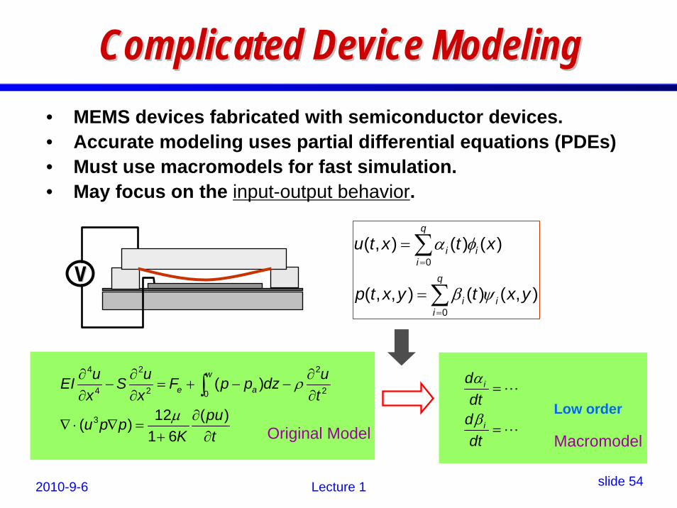
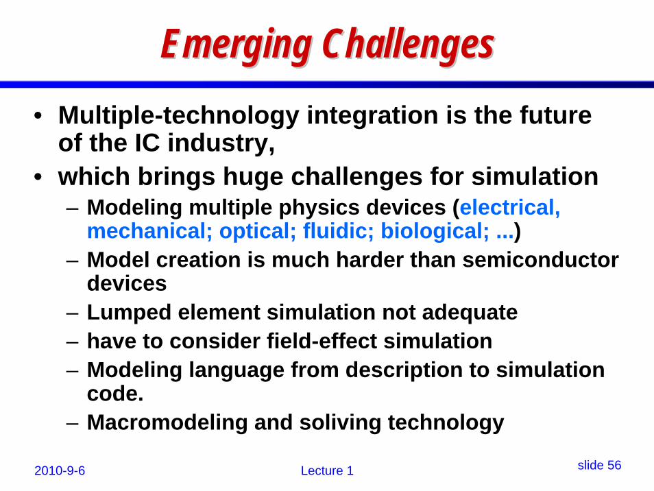
Complicated Device Modeling Complicated Device Modeling • MEMS devices fabricated with semiconductor devices.• Accurate modeling uses partial differential equations (PDEs)• Must use macromodels for fast simulation.• May focus on the input-output behavior.

Low order

Original Model Macromodel

VV0

0

( , ) ( ) ( )

( , , ) ( ) ( , )

q

i ii

q

i ii

u t x t x

p t x y t x y

α φ

β ψ

=

=

=

=

4 2 2

4 2 20

3

( )

12 ( )( )1 6

w

e au u uEI S F p p dz

x x tpuu p p

K t

ρ

μ

∂ ∂ ∂− = + − −

∂ ∂ ∂∂

∇ ⋅ ∇ =+ ∂

∫ i

i

ddt

ddt

α

β

=

=

2010-9-6 Lecture 1 slide 55

MultipleMultiple--Technology IntegrationTechnology Integration

A MEMS Chip

A single-chip receiver

The existing design and fabrication problems that challenge the CAD engineers!

2010-9-6 Lecture 1 slide 56

Emerging ChallengesEmerging Challenges• Multiple-technology integration is the future

of the IC industry,• which brings huge challenges for simulation

– Modeling multiple physics devices (electrical, mechanical; optical; fluidic; biological; ...)

– Model creation is much harder than semiconductor devices

– Lumped element simulation not adequate– have to consider field-effect simulation– Modeling language from description to simulation

code.– Macromodeling and soliving technology

2010-9-6 Lecture 1 slide 57

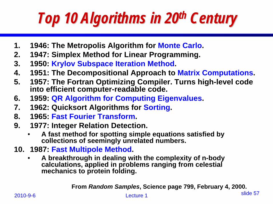
Top 10 Algorithms in 20Top 10 Algorithms in 20thth CenturyCentury1. 1946: The Metropolis Algorithm for Monte Carlo. 2. 1947: Simplex Method for Linear Programming. 3. 1950: Krylov Subspace Iteration Method. 4. 1951: The Decompositional Approach to Matrix Computations. 5. 1957: The Fortran Optimizing Compiler. Turns high-level code

into efficient computer-readable code. 6. 1959: QR Algorithm for Computing Eigenvalues. 7. 1962: Quicksort Algorithms for Sorting. 8. 1965: Fast Fourier Transform. 9. 1977: Integer Relation Detection.

• A fast method for spotting simple equations satisfied by collections of seemingly unrelated numbers.

10. 1987: Fast Multipole Method. • A breakthrough in dealing with the complexity of n-body

calculations, applied in problems ranging from celestial mechanics to protein folding.

From Random Samples, Science page 799, February 4, 2000.

2010-9-6 Lecture 1 slide 58

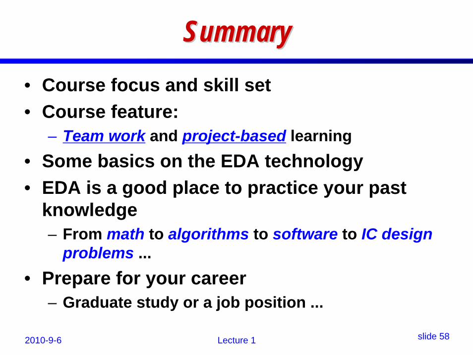
SummarySummary• Course focus and skill set• Course feature:

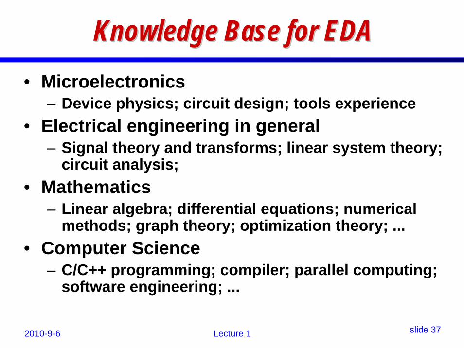
– Team work and project-based learning• Some basics on the EDA technology• EDA is a good place to practice your past

knowledge– From math to algorithms to software to IC design

problems ...• Prepare for your career

– Graduate study or a job position ...


Recommended