+ All Categories
Home > Documents > Science and Langmuir Probe Experiment in the · PDF file1M.E (VLSI & Embedded System Design),...

Science and Langmuir Probe Experiment in the · PDF file1M.E (VLSI & Embedded System Design),...

Date post: 27-Mar-2018
Category:
Upload: hoangdang
View: 218 times
Download: 0 times
Share this document with a friend
5
© 2015 IJEDR | Volume 3, Issue 2 | ISSN: 2321-9939 IJEDR1502192 International Journal of Engineering Development and Research ( www.ijedr.org) 1167 Science and Langmuir Probe Experiment in the Ionosphere of Mars 1 Barot jigar, 2 S.A.Haider, 3 Dr.Y.B.Acharya 1 M.E (VLSI & Embedded System Design), 2 Senior Professor PRL, 3 Scientist PRL 1 Gujarat Technological University 1 Ahmedabad, Gujarat, India ________________________________________________________________________________________________________ Abstract - The new concept of Langmuir probe has been developed for measurement of electron densities, ion densities, and electron temperatures in the MARS ionosphere. Here this article we discuss how a Langmuir Probe can be used to study mars ionosphere. It works on basic principle of the Langmuir Probe. Here in this paper we describe the about design, implementation and laboratory result. We have prepped flow of the architecture of this system (see figure1).The basic principle of the Langmuir Probe where it can be used for find out the plasma parameters. The Langmuir Probe experiment consist gold coated cylindrical sensor is input stage of the system. We apply to sweep voltage to sensor for generating current. The sensor has kept in plasma if we apply the positive current sensor exposed with negative ion the collect the current. After the current voltage charatertics we analyzed the plasma parameters like electron density, ion density, electron temperature ect. The feedback operational amplifier has been connected with the sensor. It has input stage of the experiment system. Then output of operational amplifier is goes to differential amplifier. The differential amplifier is amplifying the difference between both signals. Later we have been used low pass filter for remove the un- wanted frequency of signal. Here the analog to digital convertor for generating a digital signal for processing. Finally analog to digital convertor is interface with microcontroller, here microcontroller is also interface with LCD. So by using microcontroller we have been display result on elemety display. Index Terms- Sweep voltage, ADC, Sensor, Operational Amplifier, Low pass filter, microcontroller, LCD display, Differential amplifier ________________________________________________________________________________________________________ I. INTRODUCTION Langmuir probe have been extensively used in the laboratory for a long time measurement of parameters such as electron and ion densities, electron and ion temperature [7]. The hypothesis of Langmuir probe was specified by Langmuir and Mott- Smith (1924) and Mott-Smith and Langmuir (1926) in two classical documents. Here the Langmuir probe experiment is being developed for the find out the find out the MARS ionosphere layer plasma parameter like electron density, ion density, electron temperature, ion temperature. Density and temperature is critical quantity to understand in the mars atmosphere. So here in this paper I explain about design and implementation result of the Langmuir probe experiment system. II. PRINCIPLE OF LANGMUIR PROBE The basic plasma parameters can be finding out by placing a conducting probe kept into the plasma and collection the current to the probe as a function of the difference between the probe and plasma space potentials. The plasma space potential is just the potential difference of the plasma volume. When the probe potential (Vp) is above the plasma space potential (Vs) the gathered electron current attain a saturated level while in region just the opposite occurs. Finally evaluating the slope of the electron current-voltage (i-v) characteristic in region the measuring the ion or electron saturation current and using the electron and ion density find out. When a positive voltage is applied to an electrical conductor or probe is kept in plasma, the negative charges attracted by it and probe is collect current. Langmuir probe measurement of ionospheric plasma density is based on this principle. The initial technique first used by Irving Langmuir consisted of exposing a small metallic probe to medium under study and measuring the current collected by collected by it as the probe voltage was slowly varied from a congenital negative voltage through zero to a convenient sweep voltage. The result current voltage charatertics were analysed to obtain information about plasma parameters. Presently, the Langmuir probe system probe is connected to a amplifier which is grounded to through sweep voltage generator. The input impedance of the amplifier is small that potential difference between probe and plasma is determined by sweep voltage. III. LANGMUIR PROBE INSTRUMENT The Langmuir Probe will be use in fixed bias mode continues measurement of the electron and ion density. The electrons are collected by Langmuir probe sensor are converted to voltage by mean of high impedance current to voltage (V- I) to get an output voltage proportional to the input current. The block diagram of the proposed Langmuir probe instrumentation has been given in figure1.The electron collected by the Langmuir Probe sensor are converted into a voltage proportional to electron density in the current to the voltage convertor stage .
Transcript

© 2015 IJEDR | Volume 3, Issue 2 | ISSN: 2321-9939

IJEDR1502192 International Journal of Engineering Development and Research (www.ijedr.org) 1167

Science and Langmuir Probe Experiment in the

Ionosphere of Mars

1Barot jigar, 2S.A.Haider, 3Dr.Y.B.Acharya 1M.E (VLSI & Embedded System Design), 2Senior Professor PRL, 3Scientist PRL

1Gujarat Technological University 1Ahmedabad, Gujarat, India

________________________________________________________________________________________________________

Abstract - The new concept of Langmuir probe has been developed for measurement of electron densities, ion densities,

and electron temperatures in the MARS ionosphere. Here this article we discuss how a Langmuir Probe can be used to

study mars ionosphere. It works on basic principle of the Langmuir Probe. Here in this paper we describe the about

design, implementation and laboratory result. We have prepped flow of the architecture of this system (see figure1).The

basic principle of the Langmuir Probe where it can be used for find out the plasma parameters. The Langmuir Probe

experiment consist gold coated cylindrical sensor is input stage of the system. We apply to sweep voltage to sensor for

generating current. The sensor has kept in plasma if we apply the positive current sensor exposed with negative ion the

collect the current. After the current voltage charatertics we analyzed the plasma parameters like electron density, ion

density, electron temperature ect. The feedback operational amplifier has been connected with the sensor. It has input

stage of the experiment system. Then output of operational amplifier is goes to differential amplifier. The differential

amplifier is amplifying the difference between both signals. Later we have been used low pass filter for remove the un-

wanted frequency of signal. Here the analog to digital convertor for generating a digital signal for processing. Finally

analog to digital convertor is interface with microcontroller, here microcontroller is also interface with LCD. So by using

microcontroller we have been display result on elemety display.

Index Terms- Sweep voltage, ADC, Sensor, Operational Amplifier, Low pass filter, microcontroller, LCD display,

Differential amplifier

________________________________________________________________________________________________________

I. INTRODUCTION

Langmuir probe have been extensively used in the laboratory for a long time measurement of parameters such as electron

and ion densities, electron and ion temperature [7]. The hypothesis of Langmuir probe was specified by Langmuir and Mott-

Smith (1924) and Mott-Smith and Langmuir (1926) in two classical documents. Here the Langmuir probe experiment is being

developed for the find out the find out the MARS ionosphere layer plasma parameter like electron density, ion density, electron

temperature, ion temperature. Density and temperature is critical quantity to understand in the mars atmosphere. So here in this

paper I explain about design and implementation result of the Langmuir probe experiment system.

II. PRINCIPLE OF LANGMUIR PROBE

The basic plasma parameters can be finding out by placing a conducting probe kept into the plasma and collection the

current to the probe as a function of the difference between the probe and plasma space potentials. The plasma space potential is

just the potential difference of the plasma volume. When the probe potential (Vp) is above the plasma space potential (Vs) the

gathered electron current attain a saturated level while in region just the opposite occurs. Finally evaluating the slope of the

electron current-voltage (i-v) characteristic in region the measuring the ion or electron saturation current and using the electron

and ion density find out.

When a positive voltage is applied to an electrical conductor or probe is kept in plasma, the negative charges attracted by it

and probe is collect current. Langmuir probe measurement of ionospheric plasma density is based on this principle. The initial

technique first used by Irving Langmuir consisted of exposing a small metallic probe to medium under study and measuring the

current collected by collected by it as the probe voltage was slowly varied from a congenital negative voltage through zero to a

convenient sweep voltage. The result current voltage charatertics were analysed to obtain information about plasma parameters.

Presently, the Langmuir probe system probe is connected to a amplifier which is grounded to through sweep voltage generator.

The input impedance of the amplifier is small that potential difference between probe and plasma is determined by sweep voltage.

III. LANGMUIR PROBE INSTRUMENT

The Langmuir Probe will be use in fixed bias mode continues measurement of the electron and ion density. The electrons are

collected by Langmuir probe sensor are converted to voltage by mean of high impedance current to voltage (V- I) to get an

output voltage proportional to the input current.

The block diagram of the proposed Langmuir probe instrumentation has been given in figure1.The electron collected by the

Langmuir Probe sensor are converted into a voltage proportional to electron density in the current to the voltage convertor stage .

© 2015 IJEDR | Volume 3, Issue 2 | ISSN: 2321-9939

IJEDR1502192 International Journal of Engineering Development and Research (www.ijedr.org) 1168

Figure1. A Proposed Framework for Langmuir Probe Experiment

Figure2. A Laboratory testing of Langmuir probe Hardware

The Langmuir probe has been developed to find out the electron-density Mars ionosphere. The golden coated cylindrical

sensor is input stage of this system. Here we discuss implementation of Langmuir Probe experiment system. We apply to sweep

voltage to sensor to collection of the current and collected current goes to feedback operational amplifier. The feedback resistor

and gain of the succeeding amplifier stage in output voltage of the system between 1 to 5 Volts. The output of the feedback

operational amplifier is goes to differential amplifier stage we also apply sweep voltage to differential amplifier so differential

amplifier have a two input one coming from sensor and another one is sweep voltage, differential amplifier is amplify difference

between both of the signals finally we got actual signal coming from sensor. Here we used opa445ap high voltage input

impedance operational amplifier.

The differential amplifier is also fed with active Low pass filter. (seefigure1), output of the differential amplifier is goes to

active filter stage. Here active filter is RC type 3rd order Low pass filter. The filter is removed unwanted frequency and reduced

aliasing error. Here we have been design low pass filter for 100Hz cut-off frequency. After the compilation process of filtering the

filtered signal goes to Analog to Digital Convertor section, here we used 8-bit analog to digital (ADC0804) with 8 bit resolution.

An ADC is interface with P89V51RD2BN microcontroller, the analog signal coming from low pass filter is continues digitalised

in ADC section and microcontroller is also interface with Liquid Crystal Display (LCD) so microcontroller is one small computer

it control all the signal coming from sensor and display the electron density ,ion density ,electron temperature on the Liquid

Crystal Display. Here see the below figure2 is a Laboratory testing of the Langmuir probe assembly hardware.

© 2015 IJEDR | Volume 3, Issue 2 | ISSN: 2321-9939

IJEDR1502192 International Journal of Engineering Development and Research (www.ijedr.org) 1169

IV. IMPLIMENTATION RESULTS

A. Sweep voltage Generating circuit-

The figure3 has shown the sweep generation system for the Langmuir Probe experiment system. The laboratory testing and

proper result of sweep voltage are shown in it. We use LM124 Operational amplifier for the design of sweep voltage generation

system. Here the sweep generating system produces range of sweep voltage between +5v to -5v.The voltage sweep is similar to

Triangle wave or saw tooth.

Figure3.A Laboratory testing of sweep voltage generating system

Theoretical result of sweep voltage it should be.

1. T (rise) = 0.4 sec of ramp from -1v to+4 v

2. T (steady) = 1 sec of fixed dc at +4 v

3. T (fall) = 0.4 sec of ramp from +4 v to -1 v

4. T (steady) = 0.2 sec of fixed dc at -1v

Figure4. A sweep voltage wave form for Langmuir Probe

B. Operational Amplifier

Operational amplifier is input stage of the Langmuir probe experiment system. We have been design feedback operational

amplifier using OPA445AP high voltage amplifier. The OPA445AP operational amplifier is capable to handle ±45V.Here blown

figure5 of hardware testing of the high voltage feedback operational amplifier and result are also shown in figure.

© 2015 IJEDR | Volume 3, Issue 2 | ISSN: 2321-9939

IJEDR1502192 International Journal of Engineering Development and Research (www.ijedr.org) 1170

Figure 5 Testing of feedback operational amplifier hardware at Laboratory

C. Differential Amplifier

The amplifier signal coming from feedback operational amplifier it is input stage of the differential amplifier. Here we

used OPA445AP high voltage amplifier shown below figure5 differential amplifier have a two input one is sensor current and

second one is sweep voltage. Here we also apply sweep voltage to differential amplifier. The differential amplifier have two input

and both the difference is amplified by differential amplifier The reason of the sweep voltage applies to differential amplifier

after differentiation we got an actual signal coming from sensor. Here blown figure of the properly indication of the operation of

the differential amplifier. Two input if the differential amplifier one is the sensor current and second one is the sweep

voltage(Vs).both are the difference is amplify by the OPA445AP differential amplifier and after the hole operation we will got a

one single ended output. And the output is current of the cylindrical sensor

Figure 6 A assembly of hardware testing of differential amplifier

D. Active Filter

The active filter is a type of analog filter that uses active component such as an amplifier. Low pass filter of our own design are

similar to cascaded filter. This circuit which are multiple feedbacks are collected in order n=3 to 8. Active filter with an order

higher than 2 are formed by properly connected in series. The basic 3rd order low pass filter in pass band the gain is +6 bd and

© 2015 IJEDR | Volume 3, Issue 2 | ISSN: 2321-9939

IJEDR1502192 International Journal of Engineering Development and Research (www.ijedr.org) 1171

drop to -3 db at cut off frequency. Here we will make a 3rd order Low pass filter using LM741 operational amplifier IC. It is used

for all the data handling system to reduced the aliasing error.

we used 3 rd order Low-pass filter is that passes signals with a frequency lower than a certain cut-off and attenuates signals

with frequencies higher than the cutoff frequency. The amount of attenuation for each frequency depends on the filter design. The

filter is sometimes called a high-cut filter, or treble cut filter in audio applications. A low-pass filter is the opposite of a high-pass

filter.

Figure7 A simulation result of 3rd order low pass filter

V. CONCLUSION

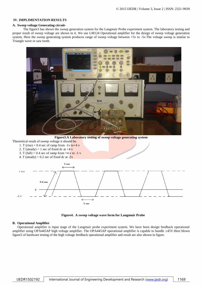
A new concept of Langmuir probe system is has been developed for the find out the plasma parameters of MARS

ionosphere. It is making it possible to derive the electron density, ion density with high resolution. The Langmuir probe has a one

cylindrical sensor to collect current and sensor have proper surface to coactions of the current. We also apply the sweep voltage

for surface potential of the sensor and it is able to generate current and by using current to voltage character tics we analyzed the

plasma property. Also by using high voltage feedback operational amplifier is able to handle high input voltage and differential

amplifier is high gain of the impedance. Here we used low pass filter for proper signal. Later using analog to digital convertor we

convertor data in digital form and by using microcontroller unit we will display result of electron density properly. The exact

value of the plasma potential provided the probe is biased at a positive value well above the estimated plasma potential. Also the

wide dynamic range of the Langmuir probe mode voltage sweep enables measurements of electron density. So proposed

Langmuir probe system is more efficient and high reliable.

VI. ACKNOWLEDGMENT

In engineering one of the best ways of studying is, while doing project, since it helps the practical knowledge of the subject,

which can be achieved successfully by putting efforts in making it successful with co-operation of teacher. I would like to express

our best regards to my project guide Prof S.A.Haider whose valuable guidance, encouragement, and provision of necessary

facilities made this work possible.

REFERENCES

[1] R. S. Dallaqua, E. Del Bosco, R. P. da Silva, and S. W. Simpson, Member, “Langmuir Probe Measurements in a Vacuum

Arc Plasma Centrifuge”, IEEE TRANSACTIONS ON PLASMA SCIENCE, VOL. 26, NO. 3, JUNE 1998

[2] Giuseppe Delle Cave and Guilin Fabricator “A Fast Circuit For Polarizing Langmuir Probes” IEEE TRANSACTIONS ON PLASMA SCIENCE, VOL. 19, NO. 4, AUGUST 1991.

[3] B. Holback1, A. Jacksén1, L. Ahlén1, S.-E. Jansson1, A. I. Eriksson1, J.-E.Wahlund1, T. Carozzi1, and J. Bergman2 LINDA – the Astrid-2 Langmuir probe instrument. Annales Geophysical (2001) 19: 601–610 c European Geophysical Society 2001.

[4] Jeremy N. Thomas, Robert H. Holzworth, and John China. A New High-Voltage Electric Field Instrument for Studying Sprites. IEEE TRANSACTIONS ON GEOSCIENCE AND REMOTE SENSING, VOL. 42, NO. 7, JULY 2004.

[5] P .Sicard, C .Boucher, A. Litnovsky, and J.-P. A compact and portable PC-based Gundestrup–Langmuir probe diagnostic system.St- Germain University du Québec-INRS, Vergennes, Québec J3X 1S2, Canada (Received 27 February 2004; accepted 10 September 2004; published online 22 December 2004).

[6] M.A.MAZIDI, J.G .MAZIDI, R.D.Mckinla-y. The 8051 Microcontroller and Embedded system, Pearson Education, 2009.

[7] Subbaraya B.H PhD Thesis, Poona University, July 1968.

[8] Microcontroller. Wikipedia [Online] http://en.wikipedia.org/wiki/Microcontroller

[9] Langmuir_probe.Wikipedia [Online] http://en.wikipedia.org/wiki/Langmuir_probe


Recommended