SCOPE OF WORK DARKE #2 PROJECT Bruns & Dahlinghaus Orphan Well Sites Darke County, Patterson Township GPS: 40.3303206°, -84.4840004° PROJECT DESCRIPTION FOR Bruns Richard #1 API No.:034-037-6-0034 Background: The Bruns #1 is located approximately 1320 feet northwest of the intersection of Reed Road/County Highway 53 and North Star-Fort Loramie Road/County Highway 18 in Patterson Township, Darke County, Ohio. This wells is situated on a 113.6-acre parcel (#M50041107000030100) owned by Richard B. and Karla R. Bruns. The physical address is 14074 Reed Road, Yorkshire, Ohio 45388. On October 4, 2005, landowner Richard Bruns filed a complaint of a potential orphan well on his property. An inspection conducted by the Division on October 13, 2005 found a well located along a grass conservation strip on the east side of Deweese Ditch, approximately 300 feet south of the field drive that runs east to west across the property. There is a large Mulberry tree growing up around the well and the well casing has been slightly bent by the tree. A twenty-five (25) foot section of exposed two (2) inch diameter production line suspended across the ditch by metal posts, which runs underground to the west. This line is also assumed to connect to three (3) other wells on the Dahlinghaus property, on east side of Reed Road. The Bruns Richard #1 is equipped with eight (8) inch diameter drive pipe, seven (7) inch diameter casing equipped with a wellhead and two (2) inch diameter tubing. An old gas meter is lying on the ground as well as some miscellaneous piping. Conversations with neighboring landowners conclude that this well was drilled approximately 60 years ago. A rudimentary courthouse search found no listing of any leases relative to this well. No known drilling, casing, cementing or completion records exist for the Bruns Richard #1. Division well records associated with the Bernard Dahlinghause #3 (API# 20009), located approximately 2500 feet east of the Bruns #1, shows that this well was drilled by Poeppelman Gas Company in 1954 to a total depth (TD) of 1211 feet into the Trenton formation. These records indicate that fresh water was encountered from 70 feet to 240 feet, that this well was equipped with 70 feet of 8.25-inch diameter casing (with a steel shoe) and 315 feet of 6.625-inch diameter casing that was equipped with a ten (10) inch rubber packer. Natural gas was encountered during drilling at 1198 feet and that this well was completed using 500 pounds of 100% gel from 1196 feet to 1211 feet. For the purposes of this scope of work, the total depth (TD) of the Bruns Richard #1 will be assumed to be 1250 feet in the Trenton Formation. The deepest underground source of drinking water (USDW) is mapped on the base of the Lockport Dolomite at an elevation of approximately 775 feet above mean sea level (amsl). The surface elevations of the permit is 964 (amsl), which puts the USDW at approximately 189 feet below ground surface (bgs); however, based upon a more recent nearby water well log #2034246 (elevation 976 feet amsl), which is 4600 feet to the east, water was encountered at a depth of 288 feet in the Lockport dolomite. DARKE #2 1/51
Transcript
SCOPE OF WORK DARKE #2 PROJECT
Bruns & Dahlinghaus Orphan Well Sites Darke County, Patterson Township
GPS: 40.3303206°, -84.4840004°
PROJECT DESCRIPTION FOR
Bruns Richard #1 API No.:034-037-6-0034
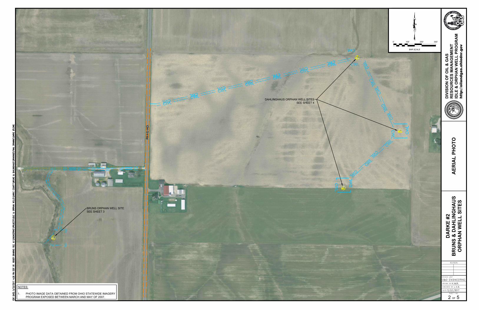
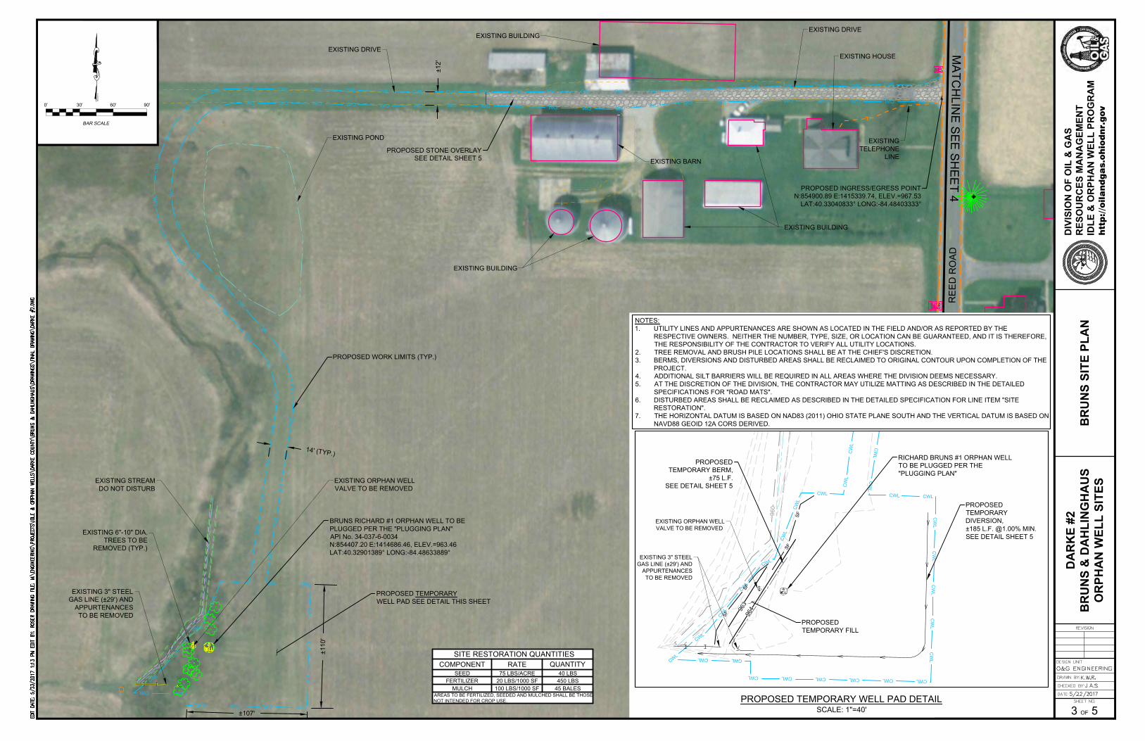
Background: The Bruns #1 is located approximately 1320 feet northwest of the intersection of Reed Road/County Highway 53 and North Star-Fort Loramie Road/County Highway 18 in Patterson Township, Darke County, Ohio. This wells is situated on a 113.6-acre parcel (#M50041107000030100) owned by Richard B. and Karla R. Bruns. The physical address is 14074 Reed Road, Yorkshire, Ohio 45388.
On October 4, 2005, landowner Richard Bruns filed a complaint of a potential orphan well on his property. An inspection conducted by the Division on October 13, 2005 found a well located along a grass conservation strip on the east side of Deweese Ditch, approximately 300 feet south of the field drive that runs east to west across the property. There is a large Mulberry tree growing up around the well and the well casing has been slightly bent by the tree. A twenty-five (25) foot section of exposed two (2) inch diameter production line suspended across the ditch by metal posts, which runs underground to the west. This line is also assumed to connect to three (3) other wells on the Dahlinghaus property, on east side of Reed Road. The Bruns Richard #1 is equipped with eight (8) inch diameter drive pipe, seven (7) inch diameter casing equipped with a wellhead and two (2) inch diameter tubing. An old gas meter is lying on the ground as well as some miscellaneous piping. Conversations with neighboring landowners conclude that this well was drilled approximately 60 years ago. A rudimentary courthouse search found no listing of any leases relative to this well.
No known drilling, casing, cementing or completion records exist for the Bruns Richard #1. Division well records associated with the Bernard Dahlinghause #3 (API# 20009), located approximately 2500 feet east of the Bruns #1, shows that this well was drilled by Poeppelman Gas Company in 1954 to a total depth (TD) of 1211 feet into the Trenton formation. These records indicate that fresh water was encountered from 70 feet to 240 feet, that this well was equipped with 70 feet of 8.25-inch diameter casing (with a steel shoe) and 315 feet of 6.625-inch diameter casing that was equipped with a ten (10) inch rubber packer. Natural gas was encountered during drilling at 1198 feet and that this well was completed using 500 pounds of 100% gel from 1196 feet to 1211 feet.
For the purposes of this scope of work, the total depth (TD) of the Bruns Richard #1 will be assumed to be 1250 feet in the Trenton Formation.
The deepest underground source of drinking water (USDW) is mapped on the base of the Lockport Dolomite at an elevation of approximately 775 feet above mean sea level (amsl). The surface elevations of the permit is 964 (amsl), which puts the USDW at approximately 189 feet below ground surface (bgs); however, based upon a more recent nearby water well log #2034246 (elevation 976 feet amsl), which is 4600 feet to the east, water was encountered at a depth of 288 feet in the Lockport dolomite.
DARKE #2
1/51
PROJECT DESCRIPTION FOR
Dahlinghaus Donald Trust #1 API No.:034-037-6-0035 Dahlinghaus Donald Trust #2 API No.:034-037-6-0036 Dahlinghaus Bernard Trust #3 API No.:034-037-2-0009
Background: The Dahlinghaus orphan wells are located approximately 2200 feet northeast of the intersection of Reed Road/County Highway 53 and North Star-Fort Loramie Road/County Highway 18 in Patterson Township, Darke County, Ohio. These wells are situated on a 60-acre parcel (#M49041107000020300) owned by Mark B. Dahlinghaus. The physical address is 14059 Reed Road, Yorkshire, Ohio 45388. These wells were first inspected by the Division in October of 2005 at the request of the landowner, Mark Dahlinghaus. This and following Division inspections, conducted in 2006 and 2012, found these wells located in the farm field in the southeast portion of the Dahlinghaus property, about 1500 feet east of Reed Road. There are no drilling, casing, cementing or completion records for these well. According to the property owner the wells were drilled by Poeppleman Gas Company approximately 60 years ago. The Dahlinghaus Donald Trust #1 is visibly equipped with eight (8) inch diameter drive pipe and two (2) inch diameter tubing. The annular space between this casing and tubing is filled with cement. The two (2) inch tubing is equipped with a bolted flange and it appears that the operator of the well used a mold around the casing to bring the cement from the top of the drive pipe to the base of the flange. The two (2) inch diameter tubing exiting the top of the flange is equipped with a gate valve and goes into a small horizontal separator located several feet from the well. The outlet side of this separator is equipped with a regulator and valves, which goes directly into a section of the exposed flowline. According to landowner, this 1.5-inch steel flowline connects this well to the three other wells associated with this project. The Dahlinghaus Donald Trust #2 is visibly equipped with 6.83-inch outside diameter (OD) casing exposed at ground level with a lip around the top. Inside this casing is a four (4) inch OD casing rising approximately three (3) feet above ground level. There is what appears to be a mount for a “grasshopper” style pump jack bolted onto the base of the four (4) inch OD casing, just above the 6.83-inch casing. There is a plug screwed into the four (4) inch collar that is reduced down to a one (1) inch diameter tubing exiting the top of the plug. This tubing is equipped with a plugged ball valve. The Dahlinghaus Bernard #3 is visibly equipped with 8.25-inch diameter drive pipe, 5.625-inch diameter casing equipped with the lower portion of a flange and 4.5-inch diameter casing. The 4.5-inch diameter casing is equipped with a four (4) inch diameter “T” fitting that is plugged on top. The side port of this fitting is equipped with a two (2) inch diameter gate valve. The outlet side of the valve is reduced down to one (1) inch tubing that appears to have been, at one time connected to the vertical drip tank located several feet from the well. The piping on the outlet side of the drip goes directly underground. According to landowner, a 1.5-inch steel flowline connects all of the wells associated with this project. No known drilling, casing, cementing or completion records exist for the Dahlinghaus Donald Trust #1 and Dahlinghaus Donald Trust #2. Division well records associated with the Dahlinghaus #3 shows that this well was drilled by Poeppelman Gas Company in 1954 to a total depth (TD) of 1211 feet into the Trenton formation. These records indicate that fresh water was encountered from 70 feet to 240 feet, that this well was equipped with 70 feet of 8.25-inch diameter casing (with a steel shoe) and 315 feet of 5.625-inch diameter casing that was equipped with a 10-inch rubber packer. Natural gas was encountered during drilling at 1198 feet and that this well was completed using 500 pounds of 100% gel from 1196 feet to 1211 feet.
DARKE #2
2/51
For the purposes of this scope of work, the total depth (TD) of all three of the Dahlinghaus wells will be assumed to be 1211 feet in the Trenton Formation. The deepest underground source of drinking water (USDW) is mapped on the base of the Lockport Dolomite at an elevation of approximately 775 feet above mean sea level (amsl). The surface elevations of the permits are surveyed between 960 and 970 (amsl), which puts the USDW at approximately 195 feet below ground surface (bgs); however, based upon a more recent nearby water well log #2034246 (elevation 976 feet amsl), which is 2300 feet to the southeast, water was encountered at a depth of 288 feet in the Lockport dolomite. Scope of Work: The project includes earthwork operations, installation of sediment controls, plugging the orphan wells, removal of onsite equipment and appurtenances as well as site restoration. Directions to the Site: From Fort Loramie, Ohio, take OH-705 west approximately 6.0 miles to Reed Road. Turn left onto Reed Road and continue for 0.5 mile to the project, which is located on both sides of the road at14059 Reed Road, Yorkshire, Ohio 45388. The Project’s latitude and longitude are 40.3303206° and -84.4840004°. Designated Route: The Contractor is required to access the site using Reed Road from OH-705 during all times of construction. These routes follow the standard legal load limit of 80,000 lbs. It is the Contractor’s responsibility to contact all County, Township, State and Municipal Officials having jurisdiction over all the roads that are intended to be utilized for this project. The Contractor shall provide written documentation to the Division, of all road use notifications/approvals prior to mobilizing equipment to the site.
DARKE #2
3/51
SCOPE OF WORK DARKE #2 PROJECT
Bruns & Dahlinghaus Orphan Well Sites Darke County, Patterson Township
GPS: 40.3303206°, -84.4840004°
GENERAL SCOPE OF WORK The Contractor, the Contractor’s agents, representatives and subcontractors shall perform this Plugging Project in accordance with Ohio Revised Code 1509, Ohio Administrative Code Chap. 1501:9-11 and 1501:9-12, the Agreement, and in accordance with the following documents that are attached hereto and made a part hereof:
1. Project Description; 2. General Scope of Work; 3. General Conditions; 4. General Specifications; 5. Sequence of Work; 6. Plugging Plan; 7. Detailed Specifications; 8. Cost Proposal Sheet; 9. & Drawing Plan Set.
Subject to the Contractor’s compliance with this Scope of Work, Contractor is solely responsible for and has control over all plugging and reclamation construction means, methods, manners, techniques, sequences, and procedures, for safety precautions and programs in connection with the Plugging Project, and for coordinating all portions of the Plugging Project.
DARKE #2
4/51
SCOPE OF WORK DARKE #2 PROJECT
Bruns & Dahlinghaus Orphan Well Sites Darke County, Patterson Township
GPS: 40.3303206°, -84.4840004°
GENERAL CONDITIONS PART 1: OHIO DEPARTMENT OF TRANSPORTATION SPECIFICATIONS This Darke #2 Project (Project) references the Ohio Department of Transportation (ODOT) Construction and Material Specifications (ODOT CMS). Any reference to these specifications is to ODOT’s most current version of the specifications. The ODOT CMS can be found at https://www.dot.state.oh.us/Divisions/ConstructionMgt/OnlineDocs/Pages/2016-Online-Spec-Book.aspx. PART 2: PRE-SITE MEETING The Contractor or Contractor's representative must attend the pre-site meeting. Failure to attend the pre-site meeting is grounds for the Division to reject a cost proposal. The Ohio Department of Natural Resources, Division of Oil & Gas Resources Management (Division) intends to begin the pre-site meeting on time. At the meeting, the Division will circulate and collect attendance sign-in forms to all contractors present. Only those contractors in attendance throughout the pre-site meeting, including the discussion of the Scope of Work, will be considered present for the pre-site meeting. PART 3: MODIFICATIONS TO THE SCOPE OF WORK PRIOR TO AWARD The Scope of Work may only be altered by written modification. The Division may issue an Addendum to the Scope of Work and will provide the Addendum by email to all Department of Administrative Services (DAS) pre-qualified contractors. Each contractor is responsible for submitting a cost proposal that is responsive to all Addenda issued. Failure to receive or acknowledge any Addenda does not release the Contractor from all obligations contained in all Addenda. All Addenda shall become part of the Scope of Work. Receipt of Addenda must be noted on the Cost Proposal. Any interpretation or clarification of the Scope of Work made by any person other than the Division, or in any manner other than a written Addendum, is not binding and the Contractor cannot rely upon any such interpretation or clarification. The Contractor cannot, at any time after the award of the Cost Proposal, be compensated for any issue with the Scope of Work, including alleging insufficient data, incomplete, ambiguous, conflicting, or erroneous language, or incorrectly assumed conditions regarding the nature or character of the work. PART 4: COST PROPOSAL PREPARATION The Contractor must submit a complete cost proposal. All cost proposals must be made on the Cost Proposal Sheet included. The Division reserves the right to reject any Cost Proposals if the Cost Proposal is nonresponsive, conditional or unbalanced. The Cost Proposal must be legibly written in ink or typed, with all amounts in numerals. For unit price items, contractors must fill in the unit price for each item listed on the Cost Proposal Sheet, and must total
DARKE #2
5/51
the items on the Cost Proposal Sheet based on the estimated quantities. If the amounts on the Cost Proposal Sheet are not totaled correctly, or where the unit price and the item total on the Cost Proposal Sheet do not agree, the Chief may exercise his discretion to determine whether the Contractor intended to use the unit price or the total line price. Any such determination by the Chief is final. The Contractor must initial any alteration or deletion of items on the Cost Proposal in ink. PART 5: WITHDRAWAL OF COST PROPOSALS At any time prior to the opening of Cost Proposals, a Contractor may submit a written request to the Division, at the location where the Cost Proposals are received, to withdraw its Cost Proposal. The request to withdraw the Cost Proposal must be signed by the person who executed the Cost Proposal. PART 6: EFFECTIVE DATE AND TERM The effective date of this Project is the date of the Letter to Proceed that is sent to the Contractor. The Project must be completed by April 1, 2018 or by June 30, 2017, whichever is sooner. If the Project terminates on June 30, 2017 and the Project is not completed, the Scope of Work may be renewed on the same terms if the Division sends written notice to the Contractor. PART 7: PROJECT BOND Once the Contractor has received the Letter to Proceed, the Contractor must supply a bond to the Division in the form of a surety bond or letter of credit in an amount equal to ten percent (10%) of the amount of the Cost Proposal, less any estimates for contingency services prior to proceeding with any work at the Project site. PART 8: TERMINATION AT WILL The Division may terminate this Scope of Work without cause. Any payment due to the Contractor at the time of termination by the Division shall be paid to the Contractor on a pro rata basis. PART 9: RELATIONSHIP BETWEEN COMPONENTS OF THE SCOPE OF WORK This Scope of Work includes drawings that are duplicates of drawings on file with the Division. The Scope of Work documents are complementary. All sections of the Scope of Work are binding. The titles and headings in the Scope of Work are for reference and in no way affect the interpretation of the provisions of the Scope of Work. Further, if any part of this Scope of Work is found to be unenforceable, no such event will affect the enforceability or applicability of any other part of the Scope of Work. If a conflict between the drawings and the specifications arises, the Contractor must notify the Division. In the event of a conflict of any provision in the Scope of Work the order of priority within the Scope of Work is as follows: Drawings, Detailed Specification, General Specifications, Plugging Plan, and Sequence of Work. PART 10: CONTRACTOR’S RESPONSIBILITY FOR SUBCONTRACTORS The Contractor is responsible for the conduct of its subcontractors and for persons its subcontractors directly or indirectly employ. PART 11: STANDARDS If the Division identifies a “standard” by reference to manufacturer and/or model number, all Cost Proposals
DARKE #2
6/51
will be evaluated to ensure that the identified standard is used. The Division will not consider a Cost Proposal in which a substitution for the standard is offered. After the Letter to Proceed is issued, the Contractor may submit a written proposal for a substitution of a standard. PART 12: SUBSTITUTIONS DURING THE PROJECT After the Letter to Proceed is issued, the Contractor may offer substitutions for the standards set forth in the Scope of Work. The decision to allow substitution is solely within the discretion of the Division, which will consider, among other factors, availability, time of delivery, the aesthetic value of the proposed substitution, general differences in the knowledge of the product, service history, quality, efficiency, performance, and architectural, engineering, inspection, testing and administrative expenses. Any changes to the Cost Proposal price and/or Scope or Work must be memorialized by a Field Order or Change Order, as applicable. The savings in cost in allowing any substitutions during the Project will be solely to the benefit of the Division. PART 13: QUANTITIES OF WORK 13.1 Unit Price Items
For items in the Cost Proposal that require a unit price, the quantities listed on the Cost Proposal Sheet are an approximation and are to be used only for the comparison of Cost Proposals. The scheduled quantities may be increased or decreased without invalidating or altering the Cost Proposal and will be considered within the Scope of Work. Payments for unit price items will be made to the Contractor for actual quantities of work performed and materials furnished in accordance with the Scope of Work; however, the Contractor may not exceed the unit quantities shown on the Cost Proposal Sheet without prior written approval of the Division through a Field Order. Even if the Contractor determines that additional unit priced quantities (above and beyond the Cost Proposal quantity) are required to meet plan and/or specification dimensions, the Contractor must not exceed the Cost Proposal Sheet quantities without prior approval of the Division. The Division will not pay for quantities above and beyond the Cost Proposal Sheet quantity without prior approval of the Division.
13.2 Lump Sum Items
For items in the Cost Proposal Sheet that require a lump sum price, the Division will not pay for work, materials or equipment that exceeds the amount provided by the Contractor on the Cost Proposal Sheet. The lump sum price on the Cost Proposal Sheet must include all work, materials and equipment necessary to properly complete the Project.
13.3 Additional/Contingency Items
The contingency items set forth in the Cost Proposal Sheet are not projected as necessary to complete the Project. Rather, the contingency items will first be used when unforeseen work arises and the Division determines the contingency item is applicable. To be compensated for contingency items, the Contractor must have a written Field Order from the Division authorizing the contingency item in a specified quantity. Use of contingency items will not require the execution of a Change Order. The Contractor must be prepared to supply all items identified in the contingency specifications for use on this Project.
DARKE #2
7/51
PART 14: OMISSIONS IN THE SCOPE OF WORK If the Contractor notices an error or omission in the Scope of Work during performance of the Project, the Contractor shall immediately notify the Division of such omission or error and shall not proceed with the Project until directed by the Division. Any work performed by the Contractor prior to clarification by the Division may not be entitled to compensation. PART 15: INTERPRETATIONS CONCERNING THE SCOPE OF WORK During the Project, if a question arises on the Scope of Work, the labor or materials to be supplied, or costs potentially exceeding the Contractor’s Cost Proposal, such questions must, prior to the work being performed, be submitted to the Division for a determination. A Division determination will be issued in writing and any work performed prior to such a determination will be performed at no cost to the Division. The Division will also begin executing a Change Order, when appropriate. If the Division receives a written question concerning the Project, the Division will determine if the work must be performed by the Contractor at no increase in price to the Scope of Work. If so, the Division will issue a Field Order setting forth the Division’s determination. Each Field Order issued must be signed by the Contractor acknowledging receipt. If the Contractor disagrees with the Division’s interpretation in a Field Order, the Contractor may submit a protest by certified mail to the Chief within ten (10) days following the date of issuance of the protested Field Order. However, the Contractor must immediately proceed with the instructions given in the issued Field Order. If, upon receipt of a written protest of a Field Order, the Division determines that the work referred to in the protest is outside the Scope of Work, the Division will not issue a Field Order and instead will issue a Change Order. Field Orders, which are interpretations of the requirements of the Scope of Work, may be issued by the Division at any time during the performance of the work. The Contractor, at all times, is required to immediately execute the instructions of all issued Field Orders. PART 16: CHANGES IN THE SCOPE OF WORK 16.1 The Division's Right to Require Change Orders
The Division may issue a Change Order directing the Contractor to immediately perform extra work that differs from the Scope of Work. The Contractor shall perform the work as directed. The changes in the work will consist of additions, deletions, or other revisions. When the Contractor performs the work, the Cost Proposal amount will be adjusted as described within this Scope of Work. If the Contractor protests the issuance of the Change Order, any such protest has no bearing on any work requirements arising out of the Change Order in that the Contractor must immediately perform the work required in the Change Order so as not to delay the progress of the work at the Project.
16.2 Unauthorized Work
Only work performed under the Scope of Work or work authorized by a Field Order or a Change Order is eligible for compensation. If the Contractor performs any work or purchases any materials without an approved, applicable Field Order or Change Order, such work performed and purchases made are within the Scope of Work at no additional cost to the Division.
DARKE #2
8/51
16.3 Contractor's May Request Change Orders
If the Contractor determines that the Scope of Work does not address conditions at the Project, the Contractor may provide written notice to the Division of the conditions and request a Change Order. No oral communications will be acceptable as justification for a Change Order.
16. 4 Determining Price of a Proposed Change Order
The following methods will be used to determine the price of a proposed Change Order: a. If a Change Order involves items not listed on the Cost Proposal Sheet, the Contractor must
present the Division with labor and/or material price quotes for the proposed Change Order item(s). The Division may request these quotes either in unit prices or as lump sums; or
b. If the work involved in the Change Order is not definable, the Division may request the work
be performed on a time and material basis and include a maximum amount to be paid for the work. The method will be based on unit prices for both labor and materials agreed to by the Division prior to the Contractor commencing the work.
16.5 Disputes Regarding Change Order Prices
If the Contractor and the Division cannot agree on the cost of the work for a Change Order, using site-specific information including, but not limited to, Division historic public cost proposal information, the Division will determine and set a fair price for the work and materials that are the subject of the Change Order.
PART 17: PAY ESTIMATES 17.1 General Information
Payments issued to the Contractor as the work progresses are not acceptance of any portion of the work not completed in accordance with the Scope of Work nor do such payments relieve the Contactor of liability with respect to any obligation or any expressed or implied warranties or responsibilities for faulty materials or workmanship.
17.2 Required Review by the Division
Prior to the submittal of each payment request, the Contractor and the Division must meet at the Project site to review the Project progress. The Contractor and the Division's Project Representative must mutually agree on quantity and percent of work completed for all cost proposal items prior to submittal of each payment request. No payment request will be approved for work that has not been approved by the Division's Project Representative. Field verification of all lump sum quantities and weight slips for all unit price quantities invoiced must be submitted to the Division’s Project Representative for review during the meeting. Payment requests received by the Division containing errors or requesting amounts that cannot be approved will be returned to the Contractor. The Contractor may resubmit a payment request after correcting errors.
DARKE #2
9/51
17.3 Documents to be Submitted for Payment
The Contractor's payment request must be submitted to the Division by regular mail to 2207 Reiser Avenue, SE, New Philadelphia, Ohio 44663. The Contractor's payment request must be submitted on a form furnished by the Division. Each request for payment must be signed by the Contractor and the Contractor must certify on the form that: a. The request for payment is accurate as to materials and the work completed under the terms
and conditions of the Scope of Work and any Change Order, as applicable, including full compliance with all labor provisions; and
b. All subcontractors and material suppliers have been paid for the work or materials that are
applicable to all previous payment requests. As certification, each request for payment, at the Division’s request, may need to be accompanied with a properly executed "Waiver of Liens" from all subcontractors and material suppliers to show that all previous payments made by the Division to the Contractor have been applied to fulfill, in full, all of the Contractor's obligations reflected in prior requests for payment.
17.4 Effect of Liens on Payment Requests
All work, materials, and equipment covered by any request for payment, whether incorporated in the Project or not, will pass to the Division at the time of payment free and clear of all liens, claims, security interests and encumbrances.
If there is evidence of any lien or claim that is chargeable to the Contractor, the Division will withhold all payments due to the Contractor to secure such lien or claim. If there are any previous liens or claims after payments are made to the Contractor, the Contractor may be required to refund to the Division a sum of money equal to the sum of all monies that the Division may be compelled to pay in discharging any lien or claim as a result of the Contractor's default.
DARKE #2
10/51
SCOPE OF WORK DARKE #2 PROJECT
Bruns & Dahlinghaus Orphan Well Sites Darke County, Patterson Township
GPS: 40.3303206°, -84.4840004°
GENERAL SPECIFICATIONS Unless there is a specific pay item in the Detailed Specifications, the work defined in the General Specification shall be incorporated into other items of work. PART 1: HOURS OF WORK The Contractor, the Contractor’s agents, representatives and subcontractors shall perform plugging projects during the days of Monday through Friday. Work will not be conducted on weekends or state/national holidays except with Division approval or during emergency situations. A work day is defined as eight (8) hours. However, additional hours may be worked with Division approval or during emergency situations. PART 2: EQUIPMENT The Contractor equipment shall pass all safety requirements of local, state, and federal agencies. The Ohio Department of Natural Resources, Division of Oil and Gas Resources Management reserves the right to inspect the equipment prior to the Notice to Proceed. Unless otherwise noted, all equipment and materials required to complete the work described shall be provided by the Contractor. PART 3: NOTIFICATIONS 3.1 Seven Working Day Notice
The Contractor, the Contractor’s agents, representatives, subcontractors, or independent contractors shall contact the responsible Division Orphan Well Inspector (the “Inspector”) no less than seven (7) working days prior to commencement of work. Notice may be written or oral. This notice will allow the appropriate Division staff time to mark the approved access route and any sensitive areas that need to be left undisturbed. The Contractor, the Contractor’s agents, representatives and sub-contractors shall contact each utility company that has utilities that directly affect plugging activities at the well location(s).
3.2 Public 48 Hour Notice
Prior to initiating well plugging operations, the Contractor shall give a minimum of 48-hour notice to the local fire department. Confirmation of this notification shall also be made to the Inspector or the Division Regional Office.
3.3 Emergency Notification
When emergency conditions are encountered, such as a release of hydrogen sulfide gas (H2S), natural gas, crude oil, condensate or brine that threatens human health, safety or the environment, as described in Ohio Administrative Code 1501:9-08-02, the Contractor shall notify the local fire
DARKE #2
11/51
department, the Local Emergency Planning Committee (LEPC) and call the 24/7 incident notification number: 1-844-OH-Call1 (1-844-642-2551) within 30 minutes of the occurrence.
PART 4: ACCESS AND PRESERVATION OF SITE Costs for the adequate access to the well site for the plugging equipment are to be included in the cost proposal. Unless waived, placement of all tanks and equipment shall be subject to Division’s approval. If requested by the Division, access roads will be chained or cabled to prevent unauthorized use. Special attention shall be given to maintaining trees and other vegetation that have scenic value, provide shade, reduce erosion and runoff, or add to the aesthetics of the area. No trees three (3) inches or larger in diameter shall be removed without the Division’s permission. Any alterations to the natural topography required to provide ingress and egress to the well site must be approved before work begins. PART 5: DAMAGE CAUSED BY CONTRACTOR All damage caused by the Contractor’s negligence in carrying out of this scope of work to any public or private property of any nature whatsoever, including trees, shrubs and crops, shall be corrected to Division’s satisfaction at the expense of the Contractor. If crops are damaged and the Contractor, landowner, or tenant cannot reach a settlement, the County Cooperative Extension Service shall set a fair price for crop damages and the decision shall be final and binding upon all parties. All subsequent payments due the Contractor shall be withheld until the Contractor provides proof of payment of any such claim. The Contractor shall be responsible for all costs of repairing or replacing any survey monument that is disturbed or destroyed by the Contractor. The Contractor shall utilize a professional surveyor who is licensed and registered by the State of Ohio to perform the re-establishment of said monuments according to the standards set forth by the governing body or law of said monument. For the purpose of this scope of work, the term survey monument shall apply to any property boundary marker, federal, state or county geodetic benchmark, state or county right of way monument, FEMA benchmarks or flood elevation markers. PART 6: SAFETY 6.1 Public Safety Coordination Meeting
The Contractor shall hold a safety meeting with the local fire department, Division Emergency Operations staff and Inspector, and other applicable contracting staff prior to commencement of plugging activities. The meeting shall review 1) the safety of the public during operations, 2) the safety of workers during operations, 3) emergency notifications of events, 4) site set up and layout, 5) general overview of operations, (6) nearest hospital’s address and directions.
6.2 Daily Safety Meetings
The Contractor shall hold a daily safety meeting for all personnel on-site prior to the commencement of work. The Contractor will also provide and maintain a sign in/out sheet for all people on location. The Contractor will immediately report any accidents and/or safety concerns to the Inspector.
6.3 Operational Standards
The Contractor shall follow the rules established by Occupational Safety and Health Administration (OSHA) Basic Construction Safety 29 CFR 1926 on all onsite project operations.
DARKE #2
12/51
6.4 Excavation and Trenching Requirements
The Contractor shall follow the notification protocol as specified in Part 3 of the General Specifications before the start of any excavating activities. The Contractor will comply with OSHA Construction Standards for excavation and trenching under 29CFR 1926 Subpart P.
6.5 Hazardous Communications Requirements
The Contractor shall maintain Safety Data Sheets (SDS) for all chemicals stored and/or used on-site. A copy of all SDS will be supplied to the local Fire Department and to the Division.
6.6 Site Security
The Contractor shall provide and install protective barriers/fencing around the work area to prevent unauthorized access. Ingress and Egress access must be maintained at all times.
6.7 Wind Direction Indicator The Contractor shall install a windsock in an open area of the well location where it is visible to all onsite personnel. It shall be constructed of high visibility material and deployed no less than six (6) feet above grade during the plugging operations.
6.8 Muster and Smoking Areas
The Contractor shall mark and assign a primary and a secondary muster area daily upwind of the well location. These are to be determined based on prevailing wind direction, as indicated by the windsock. The Contractor will post an emergency contact information sheet at each muster site. The Contractor will establish a safe location for a designated smoking area.
6.9 Ignition Sources and Parking Areas The Contractor shall identify and mark all potential ignition sources within a 50-foot radius of the well. The designated parking area will be outside the 50-foot radius from the well.
6.10 Air Monitoring and Worker Safety The Contractor shall supply and place a 4-gas monitor at the wellhead. The gas monitor must be calibrated and maintained to monitor Methane (CH4), Oxygen (O2), Carbon Monoxide (CO) and Hydrogen Sulfide (H2S).
Stop work must be followed when any of the levels listed below occur: • Methane - 1000 parts per million (PPM)/5% Lower Explosive Limit (LEL), • Oxygen - saturation below 19.5% or above 23%, • Carbon Monoxide – 50 PPM, • Hydrogen Sulfide - 10 PPM. The levels stated above are directly from the Occupational Safety and Health Administration (OSHA) and The National Institute for Occupational Safety and Health (NIOSH) and are standard for air monitoring procedures for safety and work environments. If any of the above levels are alarmed, all personnel will shut down ignition sources and report to the muster area. From the muster area, the Contractor will call 911 for assistance from the local Fire Department.
DARKE #2
13/51
Division Emergency Operations personnel or the Inspector has the right to stop work if the actions are unsafe or the actions cause or are likely to cause danger to the workers, public, or the environment.
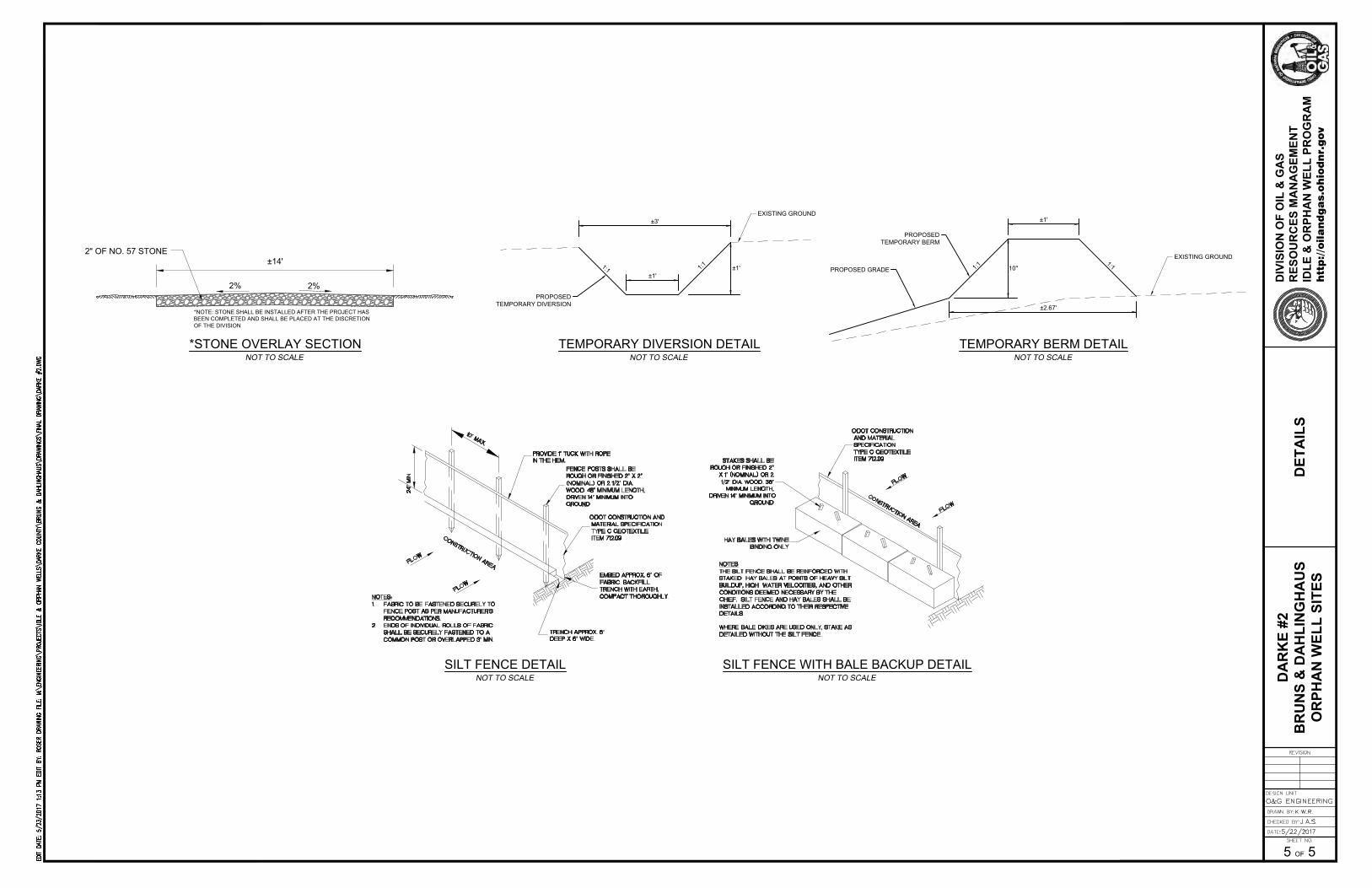
PART 7: MAINTENANCE OF TRAFFIC The Contractor shall at all times install, maintain, and operate all traffic and traffic control devices in conformance with the requirements of the "Ohio Manual of Uniform Traffic Control Devices for Streets and Highways," hereinafter called The Ohio Manual. The Contractor shall notify the appropriate public officials and the Division and shall obtain all required approvals prior to any lane closure of a public road. The Contractor shall maintain ingress/egress to all properties associated with the project at all times during the project unless agreed upon in writing by the Division and the landowner. PART 8: PROTECTION OF EXISTING UTILITIES Before construction begins, the Contractor, acting as an agent for the Division, shall locate all utilities in the vicinity of the work. The Contractor shall be responsible for complying with the regulations pertaining to utilities in the State of Ohio. The Contractor shall assume all risk for all utilities located in the vicinity of the work, whether above or below the surface of the ground. The Contractor shall also be responsible for all damages and assume all expense for direct or indirect injury, caused by his work, to any of the utilities, or any person or property by reason of injury to them, whether such utilities are or are not shown on the drawings, once they have been uncovered by the work. In compliance with Ohio Revised Code 3781, two working days before digging the Contractor shall call the Ohio Utility Protection Service (Telephone: 1-800-362-2764). The Contractor shall maintain a current OUPS call ticket for the duration of the Project. The Contractor shall also be responsible for contacting the Oil and Gas Producers Underground Protection Service (Telephone: 1-800-925-0988). PART 9: EROSION AND SEDIMENT CONTROL Temporary erosion control measures are required during the duration of the Project. These measures may consist of the installation of straw bale dikes, silt fence, filter socks, inlet protection structures, erosion control blankets, energy dissipation, and temporary seeding and mulching. Once construction begins, the Contractor shall be solely responsible for all construction related to the control of off-site sedimentation. This sediment shall be removed by the Contractor at the Division's direction. 9.1 Temporary Measures
Temporary erosion control structures shown on the Drawing Plan Set, identified with these specifications, or as directed by the Division shall be placed as soon as construction starts and must be maintained during the duration of the project. At the direction of the Division, the Contractor shall remove the temporary controls when they are no longer needed or when required permanent control measures have been completed. If sediment escapes the site, accumulations must be removed at a frequency to minimize further negative effects, and whenever feasible, prior to the next rain event.
DARKE #2
14/51
9.2 Maximum Exposed Areas
Stabilization measures must be initiated as soon as practicable in portions of the site where construction activities have temporarily or permanently ceased, and except as provided below, must be initiated no more than seven (7) days after the construction activity in that portion of the site has temporarily or permanently ceased. Where the initiation of stabilization measures by the seventh day after construction activity temporarily or permanently ceased is precluded by snow cover, or frozen ground conditions, stabilization measures must be initiated as soon as practicable. Where construction activity on a portion of the site is temporarily ceased, and earth-disturbing activities will be resumed within fourteen (14) days, temporary stabilization measures do not have to be initiated on that portion of site. The Division shall limit the area of excavation, borrow and embankment operations in progress commensurate with the Contractor’s capability and progress in keeping the finished grading, re-soiling, mulching, seeding and other such permanent control measures current in accordance with the acceptable schedule.
9.3 Winterization
When an incomplete project will be left exposed throughout the winter season, the Contractor shall furnish the Division a plan indicating the control measures to be installed and maintained until the next construction season. If the winter period falls within the anticipated construction period of the Scope of Work and as indicated in the original approved construction schedule, control structures will be paid for by the Division at the unit prices in the cost proposal. If the project is not substantially completed prior to the winter season due to the failure of the Contractor to meet the completion date, these necessary control structures will be installed and maintained by the Contractor at his expense and these items will not be paid for under the terms of the Scope of Work, except those that are permanent facilities to be left in place in accordance with the Drawing Plans Set and Specifications.
9.4 Other Controls
Off-site vehicle tracking of sediments and the generation of dust must be minimized, and any waste must be properly disposed.
9.5 Inspections
The Division Inspector shall conduct inspections to ensure that the control practices are functional and to evaluate whether the erosion and sediment control measures are adequate and properly implemented.
9.6 Enforcement
The Division shall take appropriate steps to ensure that sedimentation does not leave the project site. The Division shall require the removal of off-site sediment by the Contractor if such sediment resulted
DARKE #2
15/51
from the Contractor’s negligence to place and maintain sediment control structures in accordance with the Drawing Plan Set and Specifications.
PART 10: SPILL PREVENTION AND REMEDIATION The Contractor is expected to prevent and, if necessary, contain and remediate any spills that may occur at the site due to plugging activities. All stationary plugging equipment on well locations that are in tiled farm fields, residential neighborhoods, parks, or in/adjacent to areas determined by the Division to be environmentally sensitive, will be staged on an impermeable liner and berm. The Contractor will have oil absorbent pads and booms available onsite during the plugging operations. PART 11: HYDROGEN SULFIDE If the well that is being plugged is known to produce hydrogen sulfide (H2S), the following considerations must be observed: 11.1 SAFETY
A. The Contractor must provide the appropriate equipment, on-site, to properly detect and abate any H2S emitted from the well. If the Contractor does not have the appropriate equipment to properly detect and abate any H2S emitted from the well, they will utilize an appropriate party to provide these services.
B. The Contractor will shut-in the well each night after the plugging operations have ceased, unless otherwise instructed by the Division. The Contractor will continue this process until the plugging operations are complete and there are no further signs of a gas release.
11.2 CEMENT
A. The Contractor will use Class A cement to plug wells known to produce hydrogen sulfide.
PART 12: CASING The Division reserves the right to require the removal and or placement of any tubing, casing, or liners deemed necessary to properly plug and abandon the well. If a string of casing that would normally be pulled cannot be removed, the Contractor may be required to log the well and perforate the casing, in accordance with the Division’s instructions, so that cement can be circulated behind the casing. The Contractor shall run an operational string of casing when caving of the well prevents clean out to depth required in the scope of work. PART 13: WELL OBSTRUCTION ASSESSMENT If an obstruction is encountered in the wellbore that prevents the Contractor from reaching total depth, the Contractor will attempt to identify/assess the nature of the obstruction and attempt to remove any obstruction deemed an impediment to the plugging operation. The Contractor will supply impression blocks as part of their normal rig equipment. PART 14: REMOVAL OF AN OBSTRUCTION The removal of an unknown obstruction that is encountered during the cleanout of a well may include the use of milling and/or fishing tooling and equipment. The Contractor will include the costs for these services
DARKE #2
16/51
on the appropriate line items in the contingency section of this cost proposal unless these costs are part of a planned procedure. The Division will approve a method for the Contractor to remove the well obstruction. The Division will first utilize contingency specifications and line items to define this work. The Division will not be responsible for milling or fishing charges that are due to Contractor negligence or Contractor equipment failure. PART 15: PLUGGED WELL IDENTIFICATION In compliance with Ohio Administrative Code 1501:9-11-10, a steel plate, a minimum of ¼-inch thick, shall be tack welded on top of all plugged wells. The well’s permit number and “ODNR” shall be welded on the plate in numbers/letters as large as practical. Letters shall have a minimum relief of 1/8-inch. PART 16: TOILET FACILITIES Where there are no readily accessible public toilet facilities, the Contractor will provide a portable field toilet on the location during plugging operations.
DARKE #2
17/51
SCOPE OF WORK DARKE #2 PROJECT
Bruns & Dahlinghaus Orphan Well Sites Darke County, Patterson Township
GPS: 40.3303206°, -84.4840004°
SEQUENCE OF WORK
General: Performance of all work shall be coordinated with the Division of Oil and Gas Resources Management (“Division”) Orphan Well Inspector (“Inspector”). The Sequence of Work for the Orphan Well Project shall be as follows: Phase I:
1) Contact the Ohio Utility Protection Service and the Ohio Oil & Gas Producers Underground Protection Service.
2) Coordinate with the Orphan Well Inspector and the local authorities for the mobilization of equipment over the roads and bridges to the site as applicable.
3) Verify with the Orphan Well Inspector that the pre-construction staking (i.e. Construction Work
Limits) has been completed by the Division.
4) Mobilize all necessary equipment to the site and install the road mats and access stone over the work area as required by the Division.
Phase II: The Contractor will plug the wells in an order that is approved by the Division. Phase II and III shall be applicable to each individual well in a repeating process for the project.
1) Implement site safety and secondary containment as described in the Detailed Specifications.
2) Install perimeter sediment controls as required by the Division.
3) Prepare the well for plugging as described in the Detailed Specifications, “Well Head Control.”
4) Upon successful installation and approval of the wellhead and establishment of well control, the Contractor shall begin to plug the well as described in the Plugging Plan and Detailed Specifications, “Well Preparation & Plugging.”
5) Once all required plugs have been placed and allowed to set, the Contractor shall cut the casing as
defined in the Plugging Plan.
6) The Contractor shall set the plugged well identification as outlined in the General Specifications and Ohio Administrative Code 1501-9-11-10.
Phase III:
1) Within three (3) working days after the plugging operations are completed, the Contractor shall remove all well and well plugging-related equipment, fluids and cuttings from the site. The
DARKE #2
18/51
Contractor shall also excavate and remove all contaminated soils present onsite if present.
2) Within fourteen (14) days after the completion of the plugging operations, the Contractor shall resoil as applicable, final grade, disc, and mulch all disturbed areas. The landowner will be responsible for planting the crop areas of the field upon completion of the plugging project, all other areas shall be seeded per the Detailed Specifications, “Site Restoration.”
3) All reclamation shall be finished to an equal or better condition than what existed prior to
construction. The Chief shall give the final approval for the restoration of the site.
DARKE #2
19/51
SCOPE OF WORK DARKE #2 PROJECT
Bruns & Dahlinghaus Orphan Well Sites Darke County, Patterson Township
GPS: 40.3303206°, -84.4840004°
PLUGGING PLAN GENERAL SUMMARY
This plugging plan shall include the Bruns Richard #1 (API: 34-037-6-0034). Further detailing of the Plugging Plan requirements can be found in the Detailed Specifications. General: The Contractor will plug the wells in an order approved by the Division. 1) The Contractor will remove the tree growing around the well casing and visually examine the existing
seven (7) inch diameter casing to evaluate its condition. If the upper portion of the casing is found to be severely degraded, the Contractor will remove the incompetent section of casing and install enough new casing, of similar diameter, to bring the top of the existing casing to ground level or a suitable working height.
2) The Contractor will install an appropriate wellhead and an approved method of well control on the
seven (7) inch diameter casing to insure gas and/or fluids generated from the well are controlled. The Contractor will maintain a minimum of 75 barrels of freshwater on location for well control.
3) The Contractor will remove the two (2) inch diameter tubing and clean out the well to its estimated
total depth of 1250 feet or a depth approved by the Division. The Contractor will stage the tubing removed from the well on pipe racks on the well site until arrangements are made for disposal at a recycling facility.
4) Once total depth has been reached and if the well is static, the Contractor will load the hole with
freshwater and run a Gamma Ray/CCL/Caliper/Bond Log to verify total depth of the well, determine the depth of the seven (7) inch diameter casing, the depth to and thickness of any cement and/or packer and confirm formation tops for cementing purposes.
5) Once logging is completed, the Contractor will circulate the hole prior to setting each plug. All free
crude oil shall be removed from the wellbore (bailed or circulated) prior to setting any plug. All cement plugs will be set through 1.5-inch diameter or larger tubing using Class A Cement, mixed at 15.6 pounds/gallon. Actual plug depths and thickness will be based on log data.
6) The Contractor will set a 300-foot Class A cement bottom plug which, based on historical drilling data,
will cover the Trenton formation. The Contractor will wait on cement a minimum of twelve (12) hours, after which they will run their tools into the hole to verify the depth to the top of the plug. Because this may be a shot hole, thieving of the cement may occur and several attempts at cementing may be required to achieve a competent bottom plug. If the plug level has dropped or it is determined that a competent plug has not been achieved, additional staged bottom plugs may be required at the discretion of the Division.
DARKE #2
20/51
7) Once a competent bottom plug is achieved and allowed to set, the Contractor will run tubing to 450 feet, circulate the hole, and set a 200-foot Class A cement plug from 450 feet to 250 feet which will cover the bottom of the seven (7) inch diameter surface casing.
8) The contractor will raise the tubing to 100 feet then set a Class A cement plug from 100 feet to 48
inches from the surface. The Contractor will check the cement level in the well after a minimum of eight (8) hours and top off the well with additional cement, if necessary.
9) Once the cement has set, the well casing will be cut off at 48-inches below grade because the well is in
an actively farmed area. The Contractor shall set the plugged well identification as outlined in the General Specifications and Ohio Administrative Code 1501-9-11-10.
POTENTIAL PLUGGING PLAN ADJUSTMENTS
1) If logging data shows that there are no zones above the Trenton that are actively producing oil and/or natural gas and the well bore can be bailed and remains dry, the Contractor may fill the well bore to within 48 inches of the surface with a Nine Sack Grout mix.
DARKE #2
21/51
SCOPE OF WORK DARKE #2 PROJECT
Bruns & Dahlinghaus Orphan Well Sites Darke County, Patterson Township
GPS: 40.3303206°, -84.4840004°
PLUGGING PLAN GENERAL SUMMARY
This plugging plan shall include the Dahlinghaus Donald Trust #1 (API: 34-037-6-0035). Further detailing of the Plugging Plan requirements can be found in the Detailed Specifications. General: The Contractor will plug the wells in an order approved by the Division. 1) The Contractor will safely relieve any pressure that may be built up in this well. The Contractor will
then remove all surface equipment and related piping associated with this well. The flowline associated with this well will be purged, capped and left in-place once all four wells in the Darke #1 Project have been plugged.
2) The Contractor will install an appropriate wellhead and an approved method of well control on the two
(2) inch diameter tubing to insure gas and/or fluids generated from the well are controlled. The Contractor will maintain a minimum of 75 barrels of fresh water on location for well control.
3) The Contractor will clean out the tubing/well to its estimated total depth of 1211 feet or a depth
approved by the Division. 4) Once total depth has been reached and the well is static, the Contractor will load the well/tubing with
freshwater and run a Gamma Ray/CCL/Caliper/Bond/Temperature Log to verify total depth of the well, determine the depth of the two (2) inch diameter tubing, the depth to and thickness of any cement and/or packer behind this tubing, record any gas producing zones in the well and confirm formation tops for cementing purposes.
5) Based on the logging data, the Contractor will run one (1) inch diameter tubing to total depth and
circulate the hole with freshwater. Circulation must be achieved. The Contractor will set a bottom plug, through the one (1) inch diameter tubing. The Class A cement will be mixed at a lighter weight (14.5-15.0 pounds/gallon) to accommodate the narrow tubing annulus. Due to the narrow tubing annulus, the Contractor will not run lost circulation material (LCM) prior to setting this cement plug. The top of this plug will be set to the base of the two (2) inch diameter tubing or the bottom packer, if present. The contractor will then pull the one (1) inch diameter tubing to just above the base of the tubing or packer and circulate out any cement in the two (2) inch diameter tubing. The Contractor will wait on cement a minimum of eight (8) hours, after which the Contractor will run their tools into the hole to verify the depth to the top of the plug. If the plug level has dropped or it is determined that a competent plug has not been achieved, additional staged bottom plugs may be required, at the discretion of the Division.
6) Once a competent bottom plug is achieved and allowed to set, the Contractor will perforate the tubing
every 25 feet from the top of the cement plug to the base of the surface cement packer using a tubing perforating gun. This will require an estimated 45 shots. The Contractor will then run tubing to the top of the cement plug, establish circulation, and cement the well in 300-foot stages to surface. The Contractor will wait on cement a minimum of eight (8) hours, after which the Contractor will check the plug level and top off with additional cement or grout, if necessary.
DARKE #2
22/51
7) Once the cement has set, the well casing will be cut off at 48-inches below grade because the well is in
an actively farmed area. The Contractor shall set the plugged well identification as outlined in the General Specifications and Ohio Administrative Code 1501-9-11-10.
DARKE #2
23/51
SCOPE OF WORK DARKE #2 PROJECT
Bruns & Dahlinghaus Orphan Well Sites Darke County, Patterson Township
GPS: 40.3303206°, -84.4840004°
PLUGGING PLAN GENERAL SUMMARY
This plugging plan shall include the Dahlinghaus Donald Trust #2 (API: 34-037-6-0036). Further detailing of the Plugging Plan requirements can be found in the Detailed Specifications. General: The Contractor will plug the wells in an order approved by the Division. 1) The Contractor will safely relieve any pressure that may be built up in this well. The Contractor will
then remove all surface equipment and related piping associated with this well. 2) The Contractor will visually examine the existing four (4) inch outside diameter casing to evaluate its
condition. If the upper portion of the casing is found to be severely degraded, the Contractor will remove the incompetent section of casing and install enough new casing, of similar diameter, to bring the top of the existing casing to ground level or a suitable working height.
3) The Contractor will install an appropriate wellhead and an approved method of well control on the 4-
inch outside diameter casing to insure there is control of gas and/or fluids generated from the well. The Contractor will maintain a minimum of 75 barrels of fresh water on location for well control.
4) The Contractor will clean out the well to its estimated total depth of 1211 feet or a depth approved by
the Division. Once total depth has been reached and the well is static, the Contractor will load the hole with fresh water and run a Gamma Ray/CCL/Caliper/Bond/Temperature Log to verify total depth of the well, determine the depth of the four (4) inch diameter casing, the depth to and thickness of any cement and/or packer behind this casing, record any gas producing zones in the well and confirm formation tops for cementing purposes.
5) Once logging is completed, the Contractor will circulate the hole prior to setting each plug. All free
crude oil shall be removed from the wellbore (bailed or circulated) prior to setting any plug. All cement plugs will be set through 1.5-inch diameter or larger tubing using Class A Cement, mixed at 15.6 pounds/gallon. Actual plug depths and thickness will be based on log data.
6) The Contractor will set a 300-foot Class A cement bottom plug which, based on historical drilling data,
will cover the Trenton formation. The Contractor will wait on cement a minimum of twelve (12) hours, after which they will run their tools into the hole to verify the depth to the top of the plug. Because this may be a shot hole, thieving of the cement may occur and several attempts at cementing may be required to achieve a competent bottom plug. If the plug level has dropped or it is determined that a competent plug has not been achieved, additional staged bottom plugs may be required at the discretion of the Division.
DARKE #2
24/51
7) Once a competent bottom plug is achieved and allowed to set, the Contractor will remove the four (4) inch diameter casing from the well. The Contractor will stage the casing removed from the well on pipe racks on the well site until arrangements are made for disposal at a recycling facility.
8) The Contractor will then run tubing to 450 feet, circulate the hole, and set a 200-foot Class A cement
plug from 450 feet to 250 feet which will cover the bottom of the 6.83-inch diameter casing.
9) The contractor will raise the tubing to 100 feet then set a Class A cement plug from 100 feet to 48 inches from the surface. The Contractor will check the cement level in the well after a minimum of eight (8) hours and top off the well with additional cement, if necessary.
10) Once the cement has set, the well casing will be cut off at 48-inches below grade because the well is in
an actively farmed area. The Contractor shall set the plugged well identification as outlined in the General Specifications and Ohio Administrative Code 1501-9-11-10.
POTENTIAL PLUGGING PLAN ADJUSTMENTS
1) If logging data shows that there are no zones above the Trenton that are actively producing oil and/or natural gas and the well bore can be bailed and remains dry, the Contractor may fill the well bore to within 48 inches of the surface with a Nine Sack Grout mix.
DARKE #2
25/51
SCOPE OF WORK DARKE #2 PROJECT
Bruns & Dahlinghaus Orphan Well Sites Darke County, Patterson Township
GPS: 40.3303206°, -84.4840004°
PLUGGING PLAN GENERAL SUMMARY
This plugging plan shall include the Dahlinghaus Donald Trust #3 (API: 34-037-2-0009). Further detailing of the Plugging Plan requirements can be found in the Detailed Specifications. General: The Contractor will plug the wells in an order approved by the Division. 1) The Contractor will visually examine the existing 4.5-inch diameter casing to evaluate its condition. If
the upper portion of the casing is found to be severely degraded, the Contractor will remove the incompetent section of casing and install enough new casing, of similar diameter, to bring the top of the existing casing to ground level or a suitable working height.
2) The Contractor will install an appropriate wellhead and an approved method of well control on the 4.5-
inch diameter casing to insure gas and/or fluids generated from the well are controlled. The Contractor will maintain a minimum of 75 barrels of freshwater on location for well control.
3) The Contractor will clean out the well to its estimated total depth of 1211 feet or a depth approved by
the Division. Once total depth has been reached and the well is static, the Contractor will load the hole with freshwater and run a Gamma Ray/CCL/Caliper/Bond/Temperature Log to verify total depth of the well, determine the depth of the 4.5-inch diameter casing, the depth to and thickness of any cement and/or packer behind this casing, record any gas producing zones in the well and confirm formation tops for cementing purposes.
4) Once logging is completed, the Contractor will circulate the hole prior to setting each plug. All free crude oil shall be removed from the wellbore (bailed or circulated) prior to setting any plug. All cement plugs will be set through 1.5-inch diameter or larger tubing using Class A Cement, mixed at 15.6 pounds/gallon. Actual plug depths and thickness will be based on log data.
5) The Contractor will set a 300-foot Class A cement bottom plug which, based on historical drilling data,
will cover the Trenton formation. The Contractor will wait on cement a minimum of twelve (12) hours, after which they will run their tools into the hole to verify the depth to the top of the plug. Because this may be a shot hole, thieving of the cement may occur and several attempts at cementing may be required to achieve a competent bottom plug. If the plug level has dropped or it is determined that a competent plug has not been achieved, additional staged bottom plugs may be required at the discretion of the Division.
6) Once a competent bottom plug is achieved and allowed to set, the Contractor will remove the 4.5-inch
diameter casing from the well. The Contractor will stage the casing removed from the well on pipe racks on the well site until arrangements are made for disposal at a recycling facility.
DARKE #2
26/51
7) The Contractor will then run tubing to 450 feet, circulate the hole, and set a 200-foot Class A cement plug from 450 feet to 250 feet which will cover the bottom of the 5.625-inch diameter surface casing.
8) The contractor will raise the tubing to 100 feet then set a Class A cement plug from 100 feet to 48
inches from the surface. The Contractor will check the cement level in the well after a minimum of eight (8) hours and top off the well with additional cement, if necessary.
9) Once the cement has set, the well casing will be cut off at 48-inches below grade because the well is in
an actively farmed area. The Contractor shall set the plugged well identification as outlined in the General Specifications and Ohio Administrative Code 1501-9-11-10.
POTENTIAL PLUGGING PLAN ADJUSTMENTS
1) If logging data shows that there are no zones above the Trenton that are actively producing oil and/or natural gas and the well bore can be bailed and remains dry, the Contractor may fill the well bore to within 48 inches of the surface with a Nine Sack Grout mix.
DARKE #2
27/51
SCOPE OF WORK DARKE #2 PROJECT
Bruns & Dahlinghaus Orphan Well Sites Darke County, Patterson Township
GPS: 40.3303206°, -84.4840004°
DETAILED SPECIFICATIONS MOBILIZATION A. Description: This work shall consist of the development of access and the mobilization of the
Contractor's forces and equipment necessary for performing the required work under the Scope of Work for the well site.
This item shall include the transportation of personnel, equipment, and supplies to and from the
site as well as the maintenance of all onsite access roads. B. Execution: No additional compensation shall be made to the Contractor for remobilization after
his equipment has been removed from the site. If applicable, this shall include remobilization of equipment if removed due to winterization of the project.
This item shall also include the removal of vegetation within the limits shown on the Drawing Plan Set in order to provide adequate space to maneuver equipment to complete the proposed work. The Contractor shall work in conjunction with the Division prior to clearing operations. Clearing may only begin with Division approval and only trees approved by the Division shall be removed. Removed vegetation shall be placed into brush piles. All brush piles shall be placed in a stable manner in a location designated by the Division in the field at the time of construction and/or as shown on the Drawing Plan Set. The Division shall make the final determination as to the stability of the constructed brush piles. Brush piles shall be free from dirt and/or non-organic debris. The Contractor shall be responsible for the repair/reconstruction of brush piles, at the discretion of the Division, up to the final acceptance of the Project. Burning of debris shall not be permitted on-site. The Contractor shall complete the grading as show on the Drawing Plan Set in order to construct the temporary fill, diversion and berm prior to mobilization of road mats and plugging equipment. The Contractor shall provide positive drainage for all areas during and after construction. All topsoil and subsoil shall be segregated. Upon successful plugging of the well, this work shall also include reclaiming the area to original contour.
Any damage to the road, drives, and/or culverts caused by the mobilization shall be repaired by the Contractor at the Contractor’s expense. All repairs shall be done equal to or better to that which existed prior to construction activities.
C. Measurement: Measurement for payment will be considered and measured as a unit satisfactorily
completed and accepted by the Division. Mobilization of equipment from well site to well site shall be considered incidental to this line item.
D. Payment: The cost of this work shall be included in the cost proposal lump sum price for
"Mobilization."
DARKE #2
28/51
SITE SAFETY A. Description: The work will include the installation and implementation of safety procedures for the
plugging of the orphan well as described herein. B. Definitions & Installation: It is the Contractor’s responsibility to properly maintain all of the latter
mentioned throughout the duration of the project. Any damages shall be repaired or replaced at no additional cost to the Division. Site safety measures shall be removed prior to the demobilization of the contractor’s workforces.
The Contractor is required to follow all requirements under General Specifications Parts 2, 6 and
8. Site safety measures shall be implemented and installed at the discretion of the Division. Any release of materials into or onto the ground or surface waters outside of the primary
and/or secondary containment shall follow the Ohio One-Call System as described in Appendix I, "Ohio One-Call." The Ohio One-Call System shall be contacted at 1-844-OHCALL1 within 30-minutes of becoming aware of the occurrence.
1. Construction Fence & Posts: The temporary construction fencing shall be composite, orange
mesh with a minimum overall height of four (4) feet. Fence posts are to be steel 1.75-inch x 3.5-inch x 5 feet t-posts. Fence materials shall meet the 2016 ODOT Construction and Materials Specficiations (CMS) Item 710.11.
The posts shall be driven in or set to a minimum depth of one (1) foot and at intervals not to exceed ten (10) feet. The fence shall be stretched and securely fastened to each post using metal or plastic ties.
2. Identifications, Markings & Plugs: All conduits capable of allowing methane migration (i.e.
ventilation pipes, storm/water drains) into the lower level of an inhabited dwelling shall be identified and capped by the contractor.
Any potential ignition sources within a fifty (50) foot radius shall be identified and marked by the contractor.
All identifications, markings, and plugs shall be inspected and approved by the Division prior to commencing with any well plugging activities.
3. Air Movers (Industrial Fans): The contractor will also be required to have onsite industrial fans
or air movers in the event natural gas is detected and found to be settling at ground level and not properly dissipating from the site.
4. Emergency Response Plan: The Contractor will assemble an Emergency Response Plan (ERP)
with all contact information, emergency preventative measures, and contingency plans for any well-related issues that may occur. The Contractor will be responsible for maintaining this ERP on site during the plugging operations. Ingress/Egress for evacuation and/or public safety will be discussed in the pre-safety meeting to be held on location by the Contractor with local responders and Division personnel. These routes will be listed in the ERP. The Division will review the ERP with the Contractor prior to beginning plugging operations.
C. Measurement: Measurement for payment will be considered and measured as a unit satisfactorily
completed and accepted by the Division. Completion of this work for each of the wells included in this project shall be considered one unit.
DARKE #2
29/51
D. Payment: Payment for this work, including labor, installation, materials and removal shall be made
at the cost proposal lump sum price for "Site Safety." SECONDARY CONTAINMENT A. Description: This item shall include all labor and materials required for the installation,
maintenance and deconstruction of the secondary containment. Onsite materials and equipment required to be stored within the secondary containment shall be as follows: containers that store liquid brine, oilfield waste, and/or fuels as well as any required pumps. In determining the method, design, and capacity for secondary containment, the contractor shall address the typical failure mode, and the most likely quantity of brine or other oil field waste substance that would be discharged.
B. Materials: The contractor shall supply catchment basins or diversion structures to intercept and
contain discharges of brine or other oilfield waste substances during the project. Materials shall consist of impermeable containers or liners made of a material that is compatible with the waste stored or used within the containment. Containment materials shall be impervious and have supporting documentation of the permeability, chemical compatibility, and other applicable QA/QC standards. Use of a liner shall be at minimum 20-mil thickness. Materials shall be durable enough to support the weight of heavy equipment used for the plugging operations. Materials shall have sufficient strength and thickness to maintain the integrity of the container or liner. The container or liner shall be designed, constructed, and maintained so that the physical and chemical characteristics of the container or liner are not adversely affected by the waste and the container or liner is resistant to physical, chemical and other failure during transportation, handling, installation and use. Liner walls shall consist of metal, wood, concrete, or plastic. Wall materials shall be designed, constructed, and maintained to withstand the overtopping and sliding forces of secondary containment filled to capacity. The Division shall determine the merit of the proposed materials compatibility, impermeability, integrity, and durability in determining if the material is sufficient for the project.
C. Installation: Secondary containment shall be installed prior to any drilling or liquid storage at the project site. Upon request of the Division, the contractor shall provide calculations in tabular format of the containment providing both the secondary containment capacity and the on-site material storage. The Division can require that sections of a secondary containment be removed for inspection and sampling if a spill occurs during the project. Installation of the containers or liners, including seams and pipe penetrations, shall be in accordance with the manufacturer’s recommendations. All seams and non-seam area of the container or liner shall be inspected by the Division for defects, holes, and blisters. Care shall be taken when operating equipment on or near the container or liner to prevent any damage to the secondary containment. If damage occurs, it shall be repaired by the contractor at his/her expense prior to continuing the project.
DARKE #2
30/51
The contractor shall retain all ownership and responsibility for the secondary containment. All secondary containment shall be removed from the site and retained by the contractor at the conclusion of the project.
D. Measurement: Secondary containment, which includes all materials, labor, and equipment necessary
to provide the required secondary containment, will be considered and measured as a unit satisfactorily completed and accepted by the Division. Secondary containment shall not be considered complete until all secondary containment has been removed from the site at the completion of the project.
E. Payment: Payment for this work shall include all material, labor, and equipment necessary to
complete the work and be made at the cost proposal per unit price per each for "Secondary Containment."
SILT FENCE A. General: This item covers construction of the silt fences and/or straw bale dikes. The Division
shall designate utilization of silt fence, straw bale dikes or a combination of both at locations selected for placement.
The placement of silt fence and straw bale dikes within the limits of construction shall be at the discretion of the Division.
During the life of the project, the contractor shall maintain these silt and erosion-control structures. Accumulated silt shall be removed when it, in the Division's opinion, may damage or reduce the effectiveness of the structure.
B. Straw Bale Dikes
1. Materials: Straw bale dikes shall be constructed with twine-bound square straw or hay bales, staked to remain in place.
2. Installation and Execution: The location of the dikes shall be as directed by the Division, at
the time of construction. When the usefulness of the dikes has ended, they shall be removed and disposed. Dikes may remain in place upon completion of the project only when permitted by the Division.
C. Silt Fence
1. Materials a. The silt fence fabric shall conform to the 2016 ODOT Item 712.09, Type C. The silt
fence shall be installed in accordance with all manufacturers' instructions. The fabric shall be free of any treatment that might significantly alter its physical
properties. During shipment and storage, the fabric shall be wrapped in a heavy-duty protective covering to protect it from direct sunlight, dirt, and other debris.
The manufacturer shall submit certified test data to cover each shipment of material.
DARKE #2
31/51
b. The silt fence used shall be a prefabricated silt fence with fabric already attached to posts or shall be assembled in the field according to the following installation guidelines.
The fabric shall be a pervious sheet composed of a strong, rot-proof polymeric yarn or fiber oriented into a stable network, which retains its relative structure during handling, placement, and long-term service. It shall have excellent resistance to deterioration from ambient temperatures, acid, and alkaline conditions, and shall be indestructible to microorganisms and insects. The material shall be resistant to deterioration by ultraviolet light and protected until placement as recommended by the manufacturer such that no deterioration occurs. During shipment and storage, the rolls of fabric shall be protected against deterioration from the sun, mud, dirt, dust and other harmful conditions at all times until their use.
2. Installation Guidelines for Silt Fence: Silt fence shall be installed in the following manner.
a. First, a small toe-in trench shall be dug along the line where the silt fence is to be
placed. The trench shall be a minimum of 6-inches deep and 6-inches wide. The excavated material shall be placed on the front or uphill side of the trench to facilitate backfilling later.
b. Next, fence posts shall be driven into the back or downstream side of the trench. The
posts shall be driven so that at least one-third (1/3) of the height of the post is in the ground. When installing a prefabricated silt fence with fabric attached to the posts, the posts shall be driven so that at least 6-inches of fabric shall be buried in the ground. Most prefabricated silt fences have posts spaced approximately 6 feet – 8 feet apart, which is usually adequate. If there is a low spot where most sediment tends to collect, the prefabricated silt fences can be backed up with bale backup. Posts shall be hardwood with sufficient strength to support a full load of deposited sediment.
c. Finally the trench shall be backfilled with the excavated material and tamped so that at
least 6-inches of the fabric is securely toed into the ground to prevent under-mining.
c. The silt fences shall be maintained throughout construction. The contractor shall conduct regular inspections and after all heavy rains. Damaged fences must be repaired immediately.
d. At the completion of construction and upon establishment of suitable vegetation as
determined by the Division, all silt fence structures shall be removed. Areas disturbed by the removal operation including temporary access roads shall be revegetated. In general, this operation shall consist of regrading, re-fertilizing, reseeding and mulching.
D. Measurement: Measurement for payment for the above-described work shall be made by actual
field measurements of quantities satisfactorily installed and completed. When using silt fence with bale backup the measurement shall be the length of the silt fence installed, plus the length of the straw bale dike installed.
E. Payment for Silt Fence and Straw Bale Dikes: Payment for this item shall be made at the cost
proposal unit price per linear foot of "Silt Fence." The Division shall only pay for quantities of items that are completed.
DARKE #2
32/51
ROAD MATS A. Description: This item shall consist of the transportation, delivery, installation, and removal of
road mats as described. The placement of road mats within the limits of construction shall be at the discretion of the Division. This item may be utilized to protect the existing drive, yard and/or the stabilization of the work area. The Division will direct work to limit the use of road mats, which shall include but may not be limited to the start of construction and the order of completion of the well plugging. Quantities not required for completion of the project will be deducted.
B. Mats: Road matting shall be timber matting; non-permeable, composite mats; or an approved
equal. Timber matting shall be composed of dense hardwood, shall be a minimum of six (6) inches thick, eight (8) feet wide, and twelve (12) feet long, and shall have a minimum of 1-1/4 inch diameter lift bolts installed at each end and through the width of the mat. Non-permeable, composite mats shall be a minimum of four (4) inches thick, eight (8) feet wide, and fourteen (14) feet long. Non-permeable, composite mats and associated components (i.e. ramps, berms, & fittings) shall be installed per the manufacturer’s recommendations.
C. Measurement: Measurement for payment for the road mats shall be made by actual field
measurements of quantities satisfactorily installed at the site. Each road mat shall be measured for a square foot installed.
For circumstances in which the Division extends the projected completion date (i.e. well obstructions, required milling operations, etc.), the contractor shall also provide a cost for "Road Mats" as a dollar amount per mat per day under "Contingency Specifications" within the original cost proposal sheet. Additional payment will be evaluated and determined by the Division.
D. Payment: The cost of this work shall be included in the cost proposal square foot price for "Road
Mats." NO. 57 STONE A. Description: This work covers the quality, material placement and requirements as a top course
stone for the existing driveway as shown in the Drawing Plan Set. B. Materials: The materials shall consist of sound and durable rock, gravel or stone of the proper
gradation meeting ODOT specifications. The material shall be free from cracks, seams, and other defects, which tend to increase deterioration from natural causes. It shall be highly resistant to weathering and disintegration under freezing and thawing and wetting and drying as evidenced by laboratory tests and/or service records. The Division at any time during the project may reject any materials, at the source or job site, not meeting the requirements of these specifications.
Acceptability of material will be determined by laboratory tests, visual inspection and/or service
records as required by the Division. Service records will include documentation to show the material has performed satisfactory on similar structures.
C. Installation: Upon delivery of the material to the site the Contractor shall install the material in
place as shown on the Drawing Plan Set. The Contractor shall not stockpile materials at the site.
DARKE #2
33/51
D. Measurement: The material shall be measured for payment by the ton (2,000 pounds) for material acceptably placed in the work as determined by certified scale weight tickets.
All material wasted or used by the Contractor for other purposes and any material not placed in the work in accordance with the requirements of the work order and these specifications and drawings shall be measured and not included for payment by weight. A conversion factor of 1.5 ton per cubic yard of No. 57 Stone shall be used if necessary.
E. Payment: Payment this work as specified above shall be made based on the cost proposal unit
price per ton for "No. 57 Stone." WELL HEAD CONTROL A. Description: This work consists of all labor, equipment, and material necessary to establish control
of the well. This item shall include the installation of a wellhead control device/flow diverter. B. Execution: The Contractor is responsible for installing, according to best management practices, a
wellhead control device/flow diverter on the well casing. The Contractor shall maintain well head control and devices for the duration of the plugging project.
The Division shall make the determination for the overall exposed depth of casing and casing
extensions. The casing shall be free from any damages or defects. If required, the casing shall be cut and cleaned of any dirt, oils and debris prior to welding extensions and/or installation of the diverter.
Once a well head control device is installed, all fluids, gases and solids generated by the plugging process will be diverted into a tank. This tank will be set a minimum of twenty (20) feet from the well. The contractor shall also maintain an adequate supply of freshwater at the well for possible well control emergencies, which shall be paid under the line item "Well Control Fluid." The contractor will install a 2-inch diameter (minimum) kill line on the well. The injection point for the kill line will be a minimum of thirty (30) feet from the well.
No plugging operations shall begin until a satisfactory inspection of the prepared well has been
completed by the Division. C. Measurement: Measurement for payment shall be made by field inspection of units satisfactorily
completed and accepted by the Division. D. Payment: Payment for the above described work, which includes all labor, materials, equipment
necessary for the well head control shall be made at the cost proposal per unit price per each for "Well Head Control."
WELL CONTROL FLUID A. Description: The work covered by this section shall consist of furnishing all labor, equipment, and
material necessary to provide and use water as a “kill” fluid for the drilling and plugging process of the well.
B. Requirements: The Contractor shall receive prior approval from the Division before using any onsite
waters for the plugging process (i.e. streams, lakes or ponds). If approved, withdrawing waters of the
DARKE #2
34/51
state shall not exceed 100,000 gallons per day from an individual water source. The Division will require a minimum of 75 barrels of freshwater be maintained on location for well control during the plugging operation.
C. Measurement: Measurement for payment for the above-described work shall be made by the actual quantity of barrels (bbls) of water used to successfully plug and/or drill the orphan well. The Division will at a minimum pay for the quantity required to be maintained on site.
D. Payment: Payment for the above work shall be made at the cost proposal unit price per barrel (bbls) for "Well Control Fluid."
LOGGING A. Description: This work consists of all labor, equipment, and material necessary to determine the
total depth (TD) of the well, depth of tubing and casing, existence of a packer, as well as the depth and thickness of the packer and any casing, if present.
B. Execution: The contractor shall complete the logging of the well bore, casing, tubing, packer,
and/or cement to the depth of the current of well bore, casing, tubing, packer, and/or cement. The methods of logging to be used shall include but not be limited to gamma ray (GR), bond, casing collar locator (CCL), caliper, and temperature log. Prior to use, the Contractor shall propose the method of logging and shall be approved by the Division.
C. Measurement: Measurement for payment shall be made by field inspection of units satisfactorily
completed and accepted by the Division. D. Payment: Payment for the above described work, which includes all labor, materials, equipment
necessary for the investigation of the well shall be made at the cost proposal per unit price per each for "Logging."
WELL PREPARATION & PLUGGING A. Description: This work consists of all labor, equipment, and material necessary to prepare the well
for plugging and complete all required plugs. This shall include drilling, clean out of the well bore to the total depth of the well, circulating the well bore prior to each plug, setting all required plugs, and verification of each plug depth.
B. Execution: The Contractor shall supply all equipment needed to complete the well preparation in
an efficient manner that will be approved by the Division. This shall include but not be limited to the rig, cementing equipment, and associated equipment.
The Contractor will drill and circulate the well bore prior to setting any casing or well plugs. The
Contractor shall identify the diameter of the well bore below the surface casing and drill with a full size bit to total depth. In any case where an obstruction is encountered and total depth cannot be achieved, the Contractor shall immediately notify the Division. The Contractor shall propose a plan to assess the nature of the obstruction that shall be approved by the Division. Additional work associated with removal of the obstruction shall be described and paid for under the “Contingency Specifications” and as listed on the Cost Proposal Sheet and agreed upon by the Division.
DARKE #2
35/51
The Contractor shall circulate the well bore with freshwater or approved drilling muds prior to cementing. Lost Circulation Material (LCM) may be used to aid in obtaining circulation, as approved by the Division. Circulation must be established prior to conducting cementing procedures. Use of LCM shall be per the “Lost Circulation Material” specification included in the Contingency Specification. LCM shall be available at the site during the completion of this line item "Well Preparation & Plugging." The well shall be in a static condition prior to beginning any cementing activities. Prior to setting any plugs the contractor shall remove all free crude oil from the wellbore either by bailing or circulating.
The Contractor shall set all plugs as described in the Plugging Plan to the depths described with
the materials described. This shall include setting any bottom plug, intermediate plugs, and the surface plug. All plugs shall be allowed to set for the periods described in the Plugging Plan. The Contractor shall determine with the required tools if any plug has dropped. If a plug has dropped or is determined to not be a competent plug, then drill out of the plug or additional staged plugs may be required at the discretion of the Division as a part of this line item. The Division reserves the right to adjust the Plugging Plan during the plugging process based on site conditions.
C. Measurement: Measurement for payment shall be made by field inspection of units satisfactorily
completed and accepted by the Division. D. Payment: Payment for the above described work, which includes all labor, materials, equipment
necessary for the well preparation and plugging shall be made at the cost proposal unit price per each for "Well Preparation & Plugging."
TUBING/DRILL PIPE A. Description: This item covers all labor, equipment, and material required to supply tubing or drill
pipe at the site for the purpose of drill out and placement of cement and spacers. B. Materials: The contractor shall supply tubing with a one (1) inch diameter and tubing with a
minimum outside 1.5-inch diameter in a condition that will allow for the pumping of cement for the purpose of plugging the well. With approval from the Division the Contractor may substitute tubing with appropriate drill pipe for use and payment of this item. Only drill pipe used at the site in place of the tubing will be paid for in this line item. Drill pipe used for drilling purposes will not be considered for payment in this line item. Otherwise drill pipe shall be considered paid for in the line item "Well Preparation & Plugging."
For this project the Contractor shall supply 1250 feet of one (1) inch diameter tubing and
1250 feet of 1.5-inch diameter or larger tubing to the project site. The Contractor shall identify the weight of the tubing supplied for quantity calculating purposes.
C. Installation: The Contractor will install and remove the tubing as necessary in order to complete
the Plugging Plan. The Contractor shall maintain ownership at the conclusion of the project of all tubing that was brought to the site for these purposes.
D. Measurement: Measurement for payment of the above-described work shall be made by actual field
measurements per linear foot of tubing delivered to the site.
DARKE #2
36/51
E. Payment: Payment for this item shall be made at the cost proposal lump sum price for "Tubing/Drill Pipe."
CLASS “A” CEMENT A. Description: This item shall cover all labor, materials, and equipment necessary to set the surface
casing and to plug the well as specified in the Plugging Plan. B. Materials: Cement materials shall be API Class “A” or with prior approval, shall be of material
conforming to 2016 ODOT CMS Item 701.04 (ASTM C150 Type I).
The cement shall not contain bentonite, fly ash, or other extenders which delay set time or decrease the overall compressive strength unless otherwise noted.
Water used for cementing shall be free of any impurities that will adversely affect set time and compressive strength.
C. Installation: The contractor shall notify the Division at least 24 hours in advance of placing
the cement. Preparation of the wellbore shall be completed per line item “Well Preparation & Plugging” prior to placement of the cement.
All cement must be mixed on-site. The cement slurry for use in the 1.5-inch tubing shall be mixed at the API recommendation, between 15.4 and 15.8 pounds per gallon. The cement slurry for use in the one (1) inch tubing shall be mixed between 14.5 and 15.0 pounds per gallon. The Class “A” Cement shall be placed to the depths and intervals described in Plugging Plan.
It is the contractor’s responsibility to provide a mud scale for weighing the cement slurry.
D. Setting: Setting times shall be completed as described in the Plugging Plan. The cement must develop a minimum compressive strength of 500 PSI after 24 hours at well bore
temperatures. The Division reserves the right to collect test cylinders throughout the duration of the cementing process.
E. Measurement: Measurement for payment shall be based on the actual quantity of sacks of cement
acceptably placed and shall be verified with delivery tickets. A sack shall be considered to be 94 pounds prior to mixing.
F. Payment: The above described work shall be paid for at the cost proposal unit price per sack for
"Class “A” Cement".
DARKE #2
37/51
PERFORATING A. Description: This work consists of all labor, equipment, and material necessary to perforate a
casing or tubing at a determined depth for the purpose of squeezing cement outside the casing or tubing string.
B. Execution: The Contractor shall complete the perforating of the casing or tubing at a depth
approved by the Division. The contractor shall propose the material and method for perforating the casing or tubing and shall be approved by the Division.
C. Measurement: Measurement for payment shall be made by field inspection of units satisfactorily
completed and accepted by the Division. D. Payment: Payment for the above described work, which includes all labor, materials, equipment
necessary for the perforating the casing or tubing made at the cost proposal per unit price per each for "Perforating."
FLUID DISPOSAL
A. Description: This item shall consist of removing and disposing of the fluid generated from the well plugging process. Fluids to be removed shall be at the discretion of the Division, and shall be injected at an approved Class II disposal well as listed on the Contractor’s Cost Proposal Sheet.
B. Material: Materials will be defined below as described for the purposes of this Scope of Work.
Contaminated Fluids: Contaminated fluid will be considered as all fluids used in the circulation of the well bore and/or fluids utilized as a “kill” substance. The Division reserves the right to deem a fluid “contaminated” at its discretion. Contaminated fluids are further defined as water that contains quantifiable concentrations of oil, natural gas(es), condensate, brine, plugging products, or other oil field waste substances. Freshwaters: Water that has not been classified as a contaminated fluid and has been stored in an uncontaminated container shall be visually inspected for oil sheen, and field tested for pH and chlorides. The chloride concentration shall be less than 250 mg/L and the pH shall be within a range of 6.5-8.5 standard units (SU). If a water is deemed as freshwater based on these inspections and tests, the contractor may discharge freshwater into or onto the land in an appropriate manner. Freshwater disposal shall not be paid for under this line item "Fluid Disposal."
C. Off-Site Disposal: Fluids designated as “contaminated” shall be hauled to an appropriate Class II
disposal well. Proof of disposal from the disposal well shall be furnished within three (3) days of acceptance to the Division.
No additional compensation shall be made for onsite fluid storage. If contaminated fluids remain
onsite, proper containment shall be established meeting all requirements as described in line item "Secondary Containment" at no additional cost to the Division. Onsite storage time shall not exceed 72 hours after plugging activities have been completed.
DARKE #2
38/51
D. Measurement: Measurement for payment shall be verified based on documentation proof of a
quantity of disposal from the disposal well utilized. E. Payment: Payment shall be made at the cost proposal unit price barrel for "Fluid Disposal." CONTAMINATED MATERIAL DISPOSAL
A. Description: This item shall consist of removing contaminated soils and cuttings from the site for off-
site disposal. Soils and cuttings to be removed shall be at the discretion of the Division, and shall be disposed of at an approved EPA licensed landfill as listed on the Contractor’s Cost Proposal Sheet.
B. Material:
Contaminated Soils/Cuttings: Contaminated soils and cuttings are defined as soils or cuttings in which oil, gas, condensate, brine, plugging products, or oil field waste substances have been released in or on the land. The Contractor will excavate and properly dispose of all soils from the location that are visibly impacted with oilfield contaminants. The Contractor shall solidify any residual fluid associated with these soils with Portland Cement, prior to removal as a part of this line item.
Soils deemed “contaminated” as a result of contractor negligence during the plugging process will
be removed and disposed of at the Contractor’s expense. Disposal procedures will conform to all requirements stated within this line item.
C. Off-Site Disposal: Soils designated as “contaminated” shall be hauled to an appropriate licensed
landfill. Copies of truck weight tickets from the landfills shall be furnished within three (3) days of acceptance to the Division.
The Division reserves the right to require soil analysis testing throughout the duration of the project.
Contaminated soil analysis testing shall be considered incidental to this line item. Contaminated soils shall be loaded and hauled away as they are excavated. No additional compensation shall be made for onsite contaminated soil storage. If excavated soils
remain onsite, proper containment shall be established meeting all requirements as described in line item "Secondary Containment" at no additional cost to the Division. Onsite storage time shall not exceed 72 hours after plugging activities have been completed.
D. Measurement: Measurement for payment shall be verified based on weight tickets of quantities
disposed at the approved EPA licensed landfill. E. Payment: Payment shall be made at the cost proposal unit price per ton for "Contaminated
Material Disposal."
DARKE #2
39/51
SALVAGE MATERIAL DISPOSAL A. Description: This item shall consist of preparing, removing, and salvaging all materials from the site
that have a salvage value as shown on the Drawing Plan Set or as required by the Chief. All items to be salvaged shall include all surface equipment, well casing, and production equipment. Salvage items shall also include any hydrocarbon materials (oil, condensate, etc.) that have a marketable value. Salvage items shall be stored onsite within the construction project limits until removed for salvage.
B. Off-Site Disposal: Prior to removal from the site the Contractor shall supply in writing to the
Division an inventory of all materials to be salvaged. On the behalf of the Division the Contractor shall salvage materials inventoried. Once materials have been salvaged the contractor shall reimburse the Division for the salvage value per the line item "Salvage Material Reimbursement."
Prior to disposal of any salvage materials from the project site, the Division will complete a
radiological assessment of salvage materials that have been provided on an inventory to the Division. The Division shall be given a minimum of two (2) working days notice to complete the assessment. Salvage materials staged on the project site shall be staged on a pipe rack where determined applicable by the Division. Salvage materials shall be on an impervious liner that will collect any residual fluids or scale.
Prior to disposal of any salvage materials the Contractor shall prepare, including cleaning, the
salvage materials for lawful salvage. C. Execution: The Contractor shall include in this line item any expense incurred with the removal
and the salvaging. D. Measurement: Measurement for payment shall be made by field inspection of units satisfactorily
completed and accepted by the Division. E. Payment: Payment shall be made at the cost proposal lump sum price for "Salvage Material
Disposal." SALVAGE MATERIAL REIMBURSEMENT
A. Description: This item shall consist of reimbursing the Division for all materials removed from the
site for salvage including all surface equipment, well casing, production equipment, and marketable hydrocarbons.
B. Reimbursement: The Contractor shall supply salvage receipts to the Division for materials
inventoried and removed from the site for salvage. The Division shall use these receipts as deduction of payment that will be represented on the Cost Proposal Sheet for this line item for this project.
C. Measurement: Measurement shall be made by salvage receipts amounts. D. Payment: Deduction shall be entered as an amount for "Salvage Material Reimbursement."
DARKE #2
40/51
SITE RESTORATION A. Description: This work shall cover all operations required to properly grade to a smooth final grade
with topsoil and blend into adjoining areas at the most moderate slope possible. Seedbed preparation through the use of scarifying equipment is also required. All site restoration work is to be completed within fourteen (14) days of the completion of the construction activities. The landowner will be responsible for planting the field in which crops are harvested upon completion of the plugging project. If the landowner does not plan to plant the site with 14 days of the completion of the project, the Contractor shall mulch the site. The Contractor shall be responsible for reestablishing vegetation disturbed outside the crop field and within the construction worklimits.
B. Materials: The materials to be used for restoration shall conform to the applicable requirements
of these specifications.
1. Mulching Material. All mulch material shall be free from mature seed bearing stalks or roots or prohibited or noxious weeds. Any type of hay is not acceptable. Mulch shall include baled wheat straw or oat straw. It shall be dry and reasonably free of weeds, stalks, or other foreign material.
2. Seed. The following seed mix shall be sown at the indicated rate. This mixture is listed by
recommended planting season and for existing site conditions, and/or intended use. Further information may be found in the Agronomy Guide, Bulletin 472, Cooperative Extension Service, The Ohio State University.
Other types of seed may be substituted if requested by the property owner(s). If such substitutions are made, they are to be made at no additional cost to the Division.
3. Fertilizer: Fertilizer shall be commercial grade (19-19-19) and shall be applied at the rate of 20-lbs/1000 sq. ft. The Contractor shall only apply fertilizer to the areas that are seeded outside of the crop field.
C. Installation:
1. Start of Work: Site restoration work shall begin as soon as possible after the completion of
construction. Final site restoration operations shall be completed within fourteen (14) working days of the final construction activities.
2. Grading: The Contractor shall deconstruct the temporary fill, diversion and berm as part of this line item. The Contractor shall provide positive drainage for all areas during and after construction.
DARKE #2
41/51
Grading shall be completed to return the site to original contouring. All topsoil and subsoil shall be segregated and replaced to near original location.
3. Area Preparation of Soil:
a. Seeded Areas. Spread and grade available topsoil uniformly over all disturbed areas
that are not within the crop field. All areas to be seeded shall be loosened by discing, harrowing, or other approved methods immediately prior to seeding. The soil shall be loosened to a depth of approximately three inches.
Following tilling of the soil, the seedbed shall be allowed to firm up. Final prepared surface shall have a smooth final grade and be appropriate for a residential
yard. Immediately following area preparation for seeding, seed shall be sown. Seed shall be sown
by approved methods that provide for uniform distribution of the seed mix as specified above.
After broadcasting or otherwise applying the seed, the surface of the seedbed shall be raked. b. Crop Field. Spread and grade available topsoil uniformly over all disturbed areas. All
areas to be disturbed shall be loosened by discing, harrowing, or other approved methods immediately prior to demobilization. The soil shall be loosened to a depth of approximately three inches.
Final prepared surface shall have a smooth final grade and be appropriate for a planting.
4. Mulching: If required, apply the equivalent of 100 pounds per 1,000 square feet of clean straw
mulch. F. Measurement: Measurement for payment of site restoration, which includes final grading topsoil,
seedbed preparation, mulching, and fertilizer application will be considered and measured as a unit satisfactorily completed and accepted by the Division.
G. Payment: Payment for this work, which includes final grading topsoil, seedbed preparation,
mulching, fertilizer application, and general cleanup shall be made at the cost proposal lump sum price for "Site Restoration."
CROP DAMAGE A. Description: This work covers the payment to the landowner for the crop damages/lost yields
required to complete the project. B. Execution: Property owner, Mark B. Dahlinghaus, shall receive a total of $1,275.00 for the
damages associated with plugging the orphan wells on his property. The physical address for the owner is 14059 Reed Road, Yorkshire, Ohio 45388.
The property owner shall be paid directly by the Contractor. The Contractor shall pay the balance of money due to property owner prior to the request of final payment from the Division. Receipt of payment
DARKE #2
42/51
(i.e. landowner waiver) from the landowner shall be furnished to the Division. Final payment will not be made to the Contractor without receipt.
C. Measurement: Areas for crop damage have been predetermined by the Division according to the construction work limits as shown on the Drawing Plan Set. Any crop damage that occurs outside of these limits shall be paid for by the Contractor.
D. Payment: Payment for the landowner shall be included in the cost proposal lump sum price for "Crop
Damage." DEMOBILIZATION A. Description: This work shall consist of the demobilization of all personnel, plugging related
equipment and materials as well as the cleanup of all areas upon completing all other work required under the Scope of Work for the well sites.
B. Execution: Any damage to the road, drives, and/or culverts caused by the demobilization shall be
repaired by the contractor at the contractor’s expense. All repairs shall be done equal to or better to that which existed prior to construction activities.
C. Measurement: Measurement for payment will be considered and measured as a unit satisfactorily
completed and accepted by the Division. Demobilization of equipment from well site to well site shall be considered incidental to this line item.
D. Payment: The cost of this work shall be included in the cost proposal lump sum price for
"Demobilization."
CONTINGENCY SPECIFICATIONS
CONTINGENCY SPECFICATIONS WILL ONLY BE AUTHORIZED VIA A FIELD ORDER FROM THE DIVISION. THE FIELD ORDER WILL DEFINE THE QUANTITY APPROVED. CONTINGENCY SPECIFICATION USE WILL BE DETERMINED BASED ON SITE CONDITIONS THAT ARE DETERMINED BY THE DIVISION. ALTERNATIVE WELL CONTROL FLUID A. Description: The work covered by this section shall consist of furnishing all labor, equipment, and
material necessary to provide and use a bentonite clay gel or a weighted brine as a “kill” fluid for the drilling and plugging process of the well.
B. Materials: Based on the onsite conditions the Contractor shall propose a brine or gel for approval from
the Division. Once a material is approved the Division will require a minimum quantity be maintained at the site during the plugging project.
B. Measurement: Measurement for payment for the above-described work shall be made by the actual quantity of barrels (bbls) of kill fluid used to successfully plug and/or drill the orphan well. The Division will at a minimum pay for the quantity required to be maintained on the site.
DARKE #2
43/51
C. Payment: Payment for the above work shall be made at the cost proposal unit price per barrel (bbls) for "Alternative Well Control Fluid."
DOWNHOLE VIDEOGRAPHY A. Description: This work consists of all labor, equipment, and material necessary to video record the
well bore in order to assess a well bore obstruction. B. Execution: The Contractor shall supply all equipment needed and complete the videography
recording of the well bore to the depth of the current obstruction. The Contractor shall supply the Division with an electronic copy of the videography recorded in a format viewable in readily available current software.
C. Measurement: Measurement for payment shall be made by the delivery of an acceptable video and
photos to the Division of the current obstruction. Measurement shall be per obstruction, not per video or photo.
D. Payment: Payment for the above described work, which includes all labor, materials, equipment
necessary for the video recording of the current obstruction made at the cost proposal per unit price per each for "Downhole Videography."
FISHING A. Description: This work consists of all labor, equipment, and material necessary to remove and/or
clear the well bore as needed in order to reach total depth by the means of fishing the obstruction in the well bore.
B. Execution: The Contractor shall supply all equipment needed to complete the fishing in an efficient
manner that will be approved by the Division. This shall include but not be limited to the rig, impression blocks, appropriate fishing tools, and associated equipment.
C. Measurement: Measurement for payment shall be made by field inspection of the actual quantity of
hours in which the drilling rig and other fishing equipment were diligently operating in a manner to remove the obstruction.
D. Payment: Payment for the above described work, which includes all labor, materials, equipment
necessary for the obstruction removal shall be made at the cost proposal per unit price per hour for "Fishing."
MILLING A. Description: This work consists of all labor, equipment, and material necessary to remove and/or
clear the well bore as needed in order to reach total depth by the means of milling the well bore. B. Execution: The Contractor shall supply all equipment needed to complete the milling in an efficient
manner that will be approved by the Division. This shall include but not be limited to the rig, swivel, mud pump, and associated equipment. Appropriate milling bits shall be provided for the
DARKE #2
44/51
circumstances encountered. Milling bits shall be factory made unless approved otherwise in writing by the Division.
C. Measurement: Measurement for payment shall be made by field inspection of the actual quantity of
hours in which the drilling rig and other milling equipment were diligently operating in a manner to remove the obstruction.
D. Payment: Payment for the above described work, which includes all labor, materials, equipment
necessary for the obstruction removal shall be made at the cost proposal per unit price per hour for "Milling."
SHOOTING A. Description: This work consists of all labor, equipment, and material necessary to sever/shoot a
casing or tubing at a determined depth for the purpose of removing the casing or tubing string by the means of shooting.
B. Execution: The Contractor shall complete the shooting of the casing or tubing at a depth approved
by the Division. The contractor shall propose the material for shooting of the casing or tubing and shall be approved by the Division.
C. Measurement: Measurement for payment shall be made by field inspection of units satisfactorily
completed and accepted by the Division. D. Payment: Payment for the above described work, which includes all labor, materials, equipment
necessary for the shooting the casing or tubing made at the cost proposal per unit price per each for "Shooting."
CUTTING/RIPPING A. Description: This work consists of all labor, equipment, and material necessary to sever/cut a
casing or tubing at a determined depth for the purpose of removing the casing or tubing string by the means of cutting or ripping.
B. Execution: The contractor shall complete the cutting/ripping of the casing or tubing at a depth
approved by the Division. The contractor shall propose the method for cutting/ripping of the casing or tubing and shall be approved by the Division.
C. Measurement: Measurement for payment shall be made by field inspection of units satisfactorily
completed and accepted by the Division. D. Payment: Payment for the above described work, which includes all labor, materials, equipment
necessary for the cutting/ripping of the casing or tubing made at the cost proposal per unit price per each for "Cutting/Ripping".
LOST CIRCULATION MATERIALS A. Description: This work shall include furnishing all labor, materials, equipment, and supplies necessary
DARKE #2
45/51
to expose portions of the well bore to lost circulation materials (LCM) as determined necessary. Lost circulation materials shall be implemented to aid in obtaining well bore circulation prior to any cementing operations.
B. Materials: Lost circulation materials shall be selected by the Contractor based on site conditions encountered and proposed to the Division for approval.
C. Measurement: Measurement for payment shall be based on the actual quantity of sacks of lost
circulation materials satisfactorily placed and shall be verified with delivery tickets. D. Payment: Payment for all the above-described work shall be made at the cost proposal unit price
per sack for "Lost Circulation Materials."
WELL CASING TAP A. Description: This work consists of all labor, equipment, and material necessary to establish
pressure relief control of the well. This item shall include the installation of a tap and valve onto the existing well casing as defined in the Plugging Plan.
B. Execution: The Contractor is responsible for tapping the well casing, installing a new valve and
“relieving” the well of any pressure according to best management practices. All components associated with the tapping process shall be of size to properly fit the steel casing
of interest and be able to withstand a minimum gas pressure of 1000 psi. The Division shall make the determination for the overall exposed depth of casing. The casing shall
be free from any damages or defects. If required, the casing shall be cleaned of any dirt, oils and debris prior to the installation of the saddle. At the discretion of the Division, further investigation of the well may be required in order to determine the adequacy of casing. This shall be paid for under line item "Logging".
After the well casing is cleaned and the saddle is installed, the Contractor will then install the valve and all associated appurtenances. Upon approval from the Division, the Contractor may tap the casing. After tapping, the Contractor shall remove the tap along with the generated “coupon” and close the installed valve. Once the valve is operational, the Contractor shall attach a two (2) inch diameter (minimum) line to the valve which will be placed into a tank. This tank will be set a minimum of twenty (20) feet from the well. The Contractor will then slowly open the valve to relieve the pressure in the well. All fluids, gases and solids generated during this process will be diverted into the tank.
No plugging operations shall begin until the well pressure has ceased and a satisfactory inspection
of the well has been completed by the Division. C. Measurement: Measurement for payment shall be made by field inspection of units satisfactorily
completed and accepted by the Division. D. Payment: Payment for the above described work, which includes all labor, materials, equipment
necessary for the well tap, valve and “relieving” process shall be made at the cost proposal unit price per each for "Well Casing Tap."
DARKE #2
46/51
NINE SACK GROUT A. Description: This work shall include furnishing all labor, materials, equipment, and supplies necessary
to plug the well as specified in the Plugging Plan.
B. Materials: Nine Sack Grout shall consist of the following materials and requirements: (SSD means saturated surface dry)
1. Cement Type I-II: Cement shall conform to 2016 ODOT CMS Item 701.02 and 701.04.
2. Sand: Sand shall be in accordance with ASTM C150. 3. Water: Water shall be in accordance with ASTM C1602.
The grout shall contain a maximum of 1% entrapped air.
Grout shall have a water to cement ratio (W/C) equal to 0.50 and an overall unit weight of 142.30 pounds per cubic foot. Slump tests may be done at the discretion of the Division. Slump requirements shall be determined in the field at the time of construction. The Division has accounted for excess materials due to loss in the well bore in the quantities on the Cost Proposal Sheet.
C. Installation: The Contractor shall notify the Division at least 24 hours in advance of placing
grout. The surface plug shall be grouted to the depths described in the Plugging Plan.
Well preparation and circulation shall be achieved as detailed in the "Well Preparation & Plugging" line item and the Plugging Plan.
D. Setting: Setting times shall be completed as described in the Plugging Plan. For the surface plug
any void space between the top of the grout and the top of the casing shall be filled to achieve a level grout line with the top of the casing.
E. Measurement: Measurement for payment for the above-described work shall be based upon material
quantities satisfactorily installed as well as delivery tickets furnished to the Division.
F. Payment: Payment for all the above-described work shall be made at the cost proposal unit price per cubic yard for "Nine Sack Grout."
Constituent SSD Weight (lbs.) Volume (ft.³)Cement Type I-II 846.00 4.30
Sand 2550.00 15.54Water 417.00 6.68
DARKE #2
47/51
SCOPE OF WORK DARKE #2 PROJECT
Bruns & Dahlinghaus Orphan Well Sites Darke County, Patterson Township
GPS: 40.3303206°, -84.4840004°
APPENDIX I – OHIO ONE-CALL
THE FOLLOWING ARE REPORTABLE INCIDENTS:
TYPE OF INCIDENT QUANTITY (GAL, BBL, PPM) ADDITIONAL FACTORS
Gas Release
N/A
Blow out
Uncontrolled Pop-off Valve (Urban Area)
Any threat to public safety
Hydrogen Sulfide (H2S) 20 ppm ; > 10 min in working area OR H2S release resulting in injury or death of person
Fire / Explosion N/A Emergency responder has been called by reporting person
Oil, Condensate or Materials Saturated with Oil or Condensate
> 210 US gallons in 24 hours Outside secondary containment & into the environment
Oil, Condensate or Materials Saturated with Oil or Condensate
> 25 US gallons in 24 hours
In an urban area AND outside secondary containment & into the environment
In an Emergency Management Zone of a surface water public drinking supply AND outside secondary containment & into the environment
In a 5-year time of travel with a groundwater-based public drinking supply AND outside secondary containment & into the environment
In a 100-year flood hazard area as delineated on the federal emergency management agency’s (FEMA) national flood insurance rate map AND outside secondary containment & into the environment
Refined Oil Products > 25 US gallons in 24 hours Outside secondary containment & into the environment
Any Oil, Condensate or Materials Saturated with Oil or Condensate / Oil (refined)
1. Controlled flaring or controlled burns authorized under Chapter 1509. of the Revised Code or under 1501:9 of the Administrative Code or authorized by the terms and conditions of a permit issued under Chapter 1509. of the Revised Code;
2. Properly functioning emission control devices authorized pursuant to Revised Code Section 3704.03;
Darke #2 ProjectDarke County, Patterson TownshipWell Names: Bruns & Dahlinghaus
Description Quantity Unit
TD = +/- 1250' - Trenton Formation
Item Total
Permit Number: Multiple
DARKE #2
50/51
29 Well Casing Tap Each
30 Nine Sack Grout C.Y.
Submitted by
City: Zip Code:
Note: Contractor shall complete the unit price and quantity for each cost proposal item listed above. The item total shall be theunit price multiplied by the quantity. Contractors shall complete all items in the above cost proposal; failure to do so may because for rejection of the cost proposal. Cost proposal quantities are only an estimate. Payment shall be based on quantities
The undersigned, having attended the required pre-site meeting, and having inspected the scope of work, hereby proposes tofurnish all labor, equipment, materials, tools, and transportation necessary to perform the proposed work in accordance with thelisted prices.
Cost Proposals shall be sealed & returned to the Department of Natural Resources, Division of Oil & Gas Resources Management,Attention: Steve Irwin, 2045 Morse Rd, Building F-3, Columbus, OH 43229, until 11:30 am on June 14, 2017.
Telephone:
Name of Contractor:
Date:
Signature:
Address:
DARKE #2
51/51
http://oilandgas.ohiodnr.gov
DIV
ISIO
N O
F O
IL &
GA
SR
ESO
UR
CES
MA
NA
GEM
ENT
IDLE
& O
RPH
AN
WEL
L PR
OG
RA
M
SHEET INDEX
CONTACT INFORMATIONDIVISION OF OIL & GAS RESOURCES MANAGEMENTOHIO DEPARTMENT OF NATURAL RESOURCES2207 REISER AVE. SENEW PHILADELPHIA, OHIO 44663PH: (330) 308-0007 FAX: (330) 308-0011
PROGRAM MANAGERGENE CHINIPH: (330) 284-2942
ORPHAN WELL INSPECTORBEN HARPSTERPH: (740) 485-9870
PROJECT ENGINEERJASON A. SIMMERMAN, P.E.PH: (330) 620-5642
Utilities ProtectionOHIO
SERVICECall Before You Dig
1-800-362-2764CALL TWO WORKING DAYS BEFORE YOU DIG(NON MEMBERS MUST BE CALLED DIRECTLY)
OIL & GAS PRODUCERS UNDERGROUNDPROTECTION SERVICE (www.ogpups.com)
1-800-925-0988
TITLE SHEETAERIAL PHOTOBRUNS SITE PLANDAHLINGHAUS SITE PLANDETAILS
12345
LOCATION MAPN
1 OF 5
TITL
E SH
EET
SCALE 1" = 1 MILE
SITE LOCATION
THIS DOCUMENT WAS ORIGINALLYISSUED BY JASON A. SIMMERMAN, P.E.
THIS DOCUMENT IS NOT CONSIDERED A SEALED DOCUMENT & IS FOR
COST PROPOSAL PURPOSES ONLY
DARKE #2
PATTERSON TOWNSHIP, DARKE COUNTY, OH
BRUNS & DAHLINGHAUS
40.3303206° N, 84.4840004° W
OHIO DEPARTMENT OF NATURAL RESOURCESDIVISION OF OIL & GAS RESOURCES MANAGEMENT
BRUNS RICHARD #1 034-037-6-0034 40.32901389° -84.48633889°
ORPHAN WELL SITES
DAHLINGHAUS DONALD TRUST #1
ORPHAN WELL INFORMATIONWELL NAME API NUMBER LATITUDE LONGITUDE
034-037-6-0035 40.33010833° -84.47898611°DAHLINGHAUS DONALD TRUST #2 034-037-6-0036 40.33124444° -84.47757778°
DAHLINGHAUS BERNARD TRUST #3 034-037-2-0009 40.33265556° -84.47870278°
DA
RK
E #2
BR
UN
S &
DA
HLI
NG
HA
US
OR
PHA
N W
ELL
SITE
S
CWLPROPOSED WORK LIMITS
EDGE OF PAVEMENT
EXISTING DRIVEEXISTING WATERSEDGE/STREAMEXISTING TOE OF SLOPE
EXISTING TOP OF BANKEXISTING GASTRANSMISSION LINE
EXISTING CONCRETE PAD
EXISTING BUILDING
EXISTING TELEPHONE LINE
EXISTING TREE
EXISTING MAILBOX
EXISTING ORPHAN WELL
EXISTING GAS VALVE
EXISTING POST
EXISTING PROPERTY LINE
EXISTING GAS LINEMARKER
EXISTING 1' CONTOURMINOREXISTING 1' CONTOURMAJOR
PROPOSED BERM
PROPOSED DIVERSIONSF SFPROPOSED SILT FENCE
960
PROPOSED CONTOUR
LEGEND
964
PROPOSED ACCESS STONE
AutoCAD SHX Text
K.W.R.
AutoCAD SHX Text
DRAWN BY:
AutoCAD SHX Text
CHECKED BY:
AutoCAD SHX Text
O&G ENGINEERING
AutoCAD SHX Text
DESIGN UNIT
AutoCAD SHX Text
OHIO DEPARTMENT OF NATURAL RESOURCES
AutoCAD SHX Text
DIVISION OF OIL & GAS RESOURCES MGMT
AutoCAD SHX Text
THE LOCATIONS OF EXISTING UNDERGROUND UTILITIES ARE SHOWN APPROXIMATELY, BASED EITHER ON REPORTING BY RESPECTIVE OWNERS AND/OR BY FIELD LOCATION. HOWEVER, THE CONTRACTOR SHALL DETERMINE THE EXACT LOCATION OF ALL EXISTING UTILITIES PRIOR TO COMMENCING WORK AND AGREES TO BE FULLY RESPONSIBLE FOR ALL DAMAGES THAT MIGHT OCCUR BY THE CONTRACTOR'S FAILURE TO EXACTLY LOCATE AND PRESERVE ALL UNDERGROUND UTILITIES. THE CONTRACTOR SHALL MAINTAIN A CURRENT 10 DAY OUPS TICKET DURING THE ENTIRE PROJECT BY CONTACTING OUPS EVERY 10 DAYS.
BRUNS RICHARD #1 ORPHAN WELL TO BEPLUGGED PER THE "PLUGGING PLAN"API No. 34-037-6-0034N:854407.20 E:1414686.46, ELEV.=963.46LAT:40.32901389° LONG:-84.48633889°
NOTES:1. UTILITY LINES AND APPURTENANCES ARE SHOWN AS LOCATED IN THE FIELD AND/OR AS REPORTED BY THE
RESPECTIVE OWNERS. NEITHER THE NUMBER, TYPE, SIZE, OR LOCATION CAN BE GUARANTEED, AND IT IS THEREFORE,THE RESPONSIBILITY OF THE CONTRACTOR TO VERIFY ALL UTILITY LOCATIONS.
2. TREE REMOVAL AND BRUSH PILE LOCATIONS SHALL BE AT THE CHIEF'S DISCRETION.3. BERMS, DIVERSIONS AND DISTURBED AREAS SHALL BE RECLAIMED TO ORIGINAL CONTOUR UPON COMPLETION OF THE
PROJECT.4. ADDITIONAL SILT BARRIERS WILL BE REQUIRED IN ALL AREAS WHERE THE DIVISION DEEMS NECESSARY.5. AT THE DISCRETION OF THE DIVISION, THE CONTRACTOR MAY UTILIZE MATTING AS DESCRIBED IN THE DETAILED
SPECIFICATIONS FOR "ROAD MATS".6. DISTURBED AREAS SHALL BE RECLAIMED AS DESCRIBED IN THE DETAILED SPECIFICATION FOR LINE ITEM "SITE
RESTORATION".7. THE HORIZONTAL DATUM IS BASED ON NAD83 (2011) OHIO STATE PLANE SOUTH AND THE VERTICAL DATUM IS BASED ON
NAVD88 GEOID 12A CORS DERIVED.
DA
RK
E #2
BR
UN
S &
DA
HLI
NG
HA
US
OR
PHA
N W
ELL
SITE
S
BAR SCALE
0' 30' 60' 90'
MA
GN
ETI
C
MA
TCH
LINE
SE
E S
HE
ET 4
SEED
SITE RESTORATION QUANTITIESCOMPONENT RATE QUANTITY
75 LBS/ACRE 40 LBSFERTILIZER 20 LBS/1000 SF 450 LBS
MULCH 100 LBS/1000 SF 45 BALESAREAS TO BE FERTILIZED, SEEDED AND MULCHED SHALL BE THOSENOT INTENDED FOR CROP USE.
*NOTE: STONE SHALL BE INSTALLED AFTER THE PROJECT HASBEEN COMPLETED AND SHALL BE PLACED AT THE DISCRETIONOF THE DIVISION
*STONE OVERLAY SECTIONNOT TO SCALE
http://oilandgas.ohiodnr.gov
DIV
ISIO
N O
F O
IL &
GA
SR
ESO
UR
CES
MA
NA
GEM
ENT
IDLE
& O
RPH
AN
WEL
L PR
OG
RA
M
5 OF 5
DET
AIL
SD
AR
KE
#2B
RU
NS
& D
AH
LIN
GH
AU
SO
RPH
AN
WEL
L SI
TES
AutoCAD SHX Text
FLOW
AutoCAD SHX Text
FLOW
AutoCAD SHX Text
24" MIN.
AutoCAD SHX Text
CONSTRUCTION AREA
AutoCAD SHX Text
10' MAX.
AutoCAD SHX Text
NOTES: THE SILT FENCE SHALL BE REINFORCED WITH STAKED HAY BALES AT POINTS OF HEAVY SILT BUILDUP, HIGH WATER VELOCITIES, AND OTHER CONDITIONS DEEMED NECESSARY BY THE CHIEF. SILT FENCE AND HAY BALES SHALL BE INSTALLED ACCORDING TO THEIR RESPECTIVE DETAILS. WHERE BALE DIKES ARE USED ONLY, STAKE AS DETAILED WITHOUT THE SILT FENCE.
AutoCAD SHX Text
NOTES: 1. FABRIC TO BE FASTENED SECURELY TO FABRIC TO BE FASTENED SECURELY TO FENCE POST AS PER MANUFACTURER'S RECOMMENDATIONS. 2. ENDS OF INDIVIDUAL ROLLS OF FABRIC ENDS OF INDIVIDUAL ROLLS OF FABRIC SHALL BE SECURELY FASTENED TO A COMMON POST OR OVERLAPPED 3" MIN.
AutoCAD SHX Text
FLOW
AutoCAD SHX Text
ODOT CONSTRUCTION AND MATERIAL SPECIFICATION TYPE C GEOTEXTILE ITEM 712.09
AutoCAD SHX Text
FLOW
AutoCAD SHX Text
CONSTRUCTION AREA
AutoCAD SHX Text
HAY BALES WITH TWINE BINDING ONLY
AutoCAD SHX Text
PROVIDE 1" TUCK WITH ROPE IN THE HEM.
AutoCAD SHX Text
FENCE POSTS SHALL BE ROUGH OR FINISHED 2" X 2" (NOMINAL) OR 2 1/2" DIA. WOOD. 48" MINIMUM LENGTH, DRIVEN 14" MINIMUM INTO GROUND
AutoCAD SHX Text
ODOT CONSTRUCTION AND MATERIAL SPECIFICATION TYPE C GEOTEXTILE ITEM 712.09
AutoCAD SHX Text
EMBED APPROX. 6" OF FABRIC. BACKFILL TRENCH WITH EARTH, COMPACT THOROUGHLY.
AutoCAD SHX Text
TRENCH APPROX. 6" DEEP X 6" WIDE.
AutoCAD SHX Text
STAKES SHALL BE ROUGH OR FINISHED 2" X 1" (NOMINAL) OR 2 1/2" DIA. WOOD. 36" MINIMUM LENGTH, DRIVEN 14" MINIMUM INTO GROUND