16
Head Start Robot Laboratory 1 Scratch the Robot Mike Freeman 15/07/2015

Head Start Robot Laboratory 1
Scratch the Robot
Mike Freeman 15/07/2015

Head Start Robot Laboratory 2
A Robot From Scratch
IntroductionThe aim of this laboratory is to construct a mobile robotic platform. This system requires:
• Sensors: electronic components that can convert information about the environment in which the robot is operating into electrical signals.
• Actuators: hardware components that can convert electrical signals intophysical actions or movements.
• Control: hardware or software components that can capture and interpret sensor data, generating a sequence of control signals to implement the correct system behaviours.
Stage 1: constructionUsing the tools and components provided, construct your robot.
D.C. Drive Motors
The robot uses two D.C. drive motors (actuators) to move and steer the platform. The D.C. motors used contains two permanent magnets and three wire coils, as shown in figure 1.
Figure 2: magnetic field interaction
Mike Freeman 15/07/2015
Permanent magnet
Permanent magnet
Coil
Figure 1: motor and gearbox (left), motor internals (right)

Head Start Robot Laboratory 3
When a voltage is connected across a coil a magnetic field is produced. This field opposes the permanent magnet's field, as shown in figure 2, i.e. the two North poles (blue) and South poles (red) generate a force that pushes the electromagnet (coil), rotating the drive shaft. To continue this rotation a mechanical switch (commutator) reverses the voltage on the coil, reversing the electromagnets field.
Using eight 10mm M3 bolts (shorter bolts) connect the two D.C. drive motors to the platform, as shown in figure 3. The base is symmetrical so the motors can be attached on either side. The bolt heads go onto the motor bracket, youmay wish to place these into position first, as shown in the top right frame of figure 3. The bolt's nut goes on the top of the base, use the long nose pilers and screwdriver to GENTLY tighten, finger tight is fine.
Tip Don't tighten the bolts until all bolts are in position, checking that the motor (wheel) is square to the base.
Figure 3: mounting drive motors
Mike Freeman 15/07/2015

Head Start Robot Laboratory 4
The front of the platform is supported by a skid. Using two 15mm M3 bolts (longer bolts) connect the skid to the platform, as shown in figure 4.
Figure 4: front skid
Servo Motor
A servo motor contains a small D.C. motor, a gearbox and control hardware, as shown in figure 5. Unlike the previous D.C. motors, when a voltage is applied the on-board hardware controller determines the position of the drive shaft i.e. 180 degrees rotation. To set the motor's position the servo is sent a voltage pulse every 20 ms (every 0.02 seconds), the width of the pulse determining the drive shaft's position, as shown in figure 6. A short pulse e.g. 0.6 ms wide, will cause the drive shaft to move to its maximum anti-clockwise position. A long pulse e.g. 2.4 ms wide, will cause the drive shaft to move to its maximum clockwise position.
Figure 5: servo motor
Using the two blue plastic washers, clamping plate and two 15mm M3 bolts (longer bolts) connect the servo motor to the platform, as shown in figure 7.
Mike Freeman 15/07/2015
Gearbox
Driveshaft
D.C. Motor
Hardware motor controller
Position sensor

Head Start Robot Laboratory 5
Figure 6: servo control signal (left), drive shaft position (right)
Tip Place the servo motor's wires through the rectangular hole first, then angle the motor housing down into the hole, it's quite a tight fit.
Figure 7: mounting servo
Mike Freeman 15/07/2015
Head Start Robot Laboratory 6
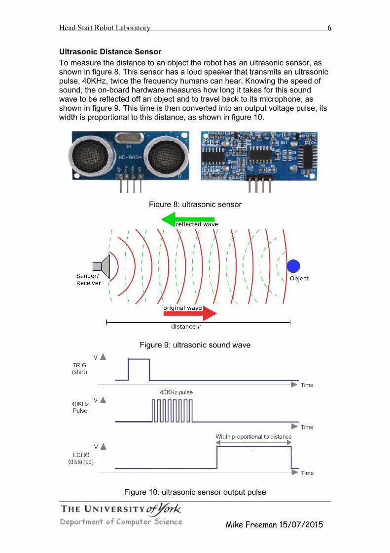
Ultrasonic Distance Sensor
To measure the distance to an object the robot has an ultrasonic sensor, as shown in figure 8. This sensor has a loud speaker that transmits an ultrasonic pulse, 40KHz, twice the frequency humans can hear. Knowing the speed of sound, the on-board hardware measures how long it takes for this sound wave to be reflected off an object and to travel back to its microphone, as shown in figure 9. This time is then converted into an output voltage pulse, its width is proportional to this distance, as shown in figure 10.
Figure 8: ultrasonic sensor
Figure 9: ultrasonic sound wave
Figure 10: ultrasonic sensor output pulse
Mike Freeman 15/07/2015

Head Start Robot Laboratory 7
Place the ultrasonic sensor into the purple bracket, ensuring the connector (pins) is pointing upwards, then gently push this onto the servo drive shaft.
Tip When connecting the bracket to the servo you may need to 'jiggle' it a littleuntil the small drive teeth mesh. Then supporting the bottom of the servo, push the bracket onto the drive shaft. Again finger tight is fine.
Figure 11: mounting the ultrasonic sensor
Controller
To control the motors and process the ultrasonic sensor data a Raspberry Pi single board computer will be used, as shown in figure 12. The Raspberry Pi has a number of General Purpose Input Output (GPIO) control pins. These are connected through the J8 header to the PiRoCon controller board, shown in figure 13, allowing the Raspberry Pi to be interfaced to the different sensorsand actuators.
Figure 12: Raspberry Pi (left), GPIO pins (right)
Mike Freeman 15/07/2015

Head Start Robot Laboratory 8
Figure 13: PiRoCon interface board
Connect the three way and four way cables to the ultrasonic sensor and servomotor. Ensure that the connectors are the correct way round. For the ultrasonic sensor the metal pins should be visible from the front. For the servothe yellow cable should be plugged into the pin marked with white paint. Finally secure all wires with the plastic clamp, as shown in figure 14.
Figure 14: Wiring
Mike Freeman 15/07/2015

Head Start Robot Laboratory 9
The robot will be controlled using a Raspberry Pi, connect the D.C. drive motor wires to motor A & B terminals. Using the small instrumentation screwdriver connect the left motor (looking from below) to the left terminal (B) and the right motor to the right terminal (A). Wire orientation is not important at this time, if needed can be corrected later.
Figure 15: D.C. Drive motors (left), ultrasonic sensor (middle), servo (right)
Figure 16: top view of Raspberry Pi + PiRoCon interface board.
Mike Freeman 15/07/2015

Head Start Robot Laboratory 10
Next connect the three way and four way connectors to the board, as shown in figure 15. Make sure that the connectors are orientated as shown.
Stage 2: manual controlWhen you have finished constructing your robot ask a demonstrator to quicklycheck your wiring, then turn on the Raspberry Pi. The robot's behaviour will bedefined using the Scratch graphical programming language. Double click on the Scratch desktop icon, then click on the OK button, as shown in figure 18.
Figure 17: main screen
Figure 18: Scratch screen
Mike Freeman 15/07/2015

Head Start Robot Laboratory 11
The Scratch programming style is very similar to the Lego Mindstorm environment used in the other practical. You can select different programmingtiles using the main menu in the top left hand corner, as shown in figure 19.
Figure 19: Scratch main menu
To control external components e.g. servo, D.C. drive motors etc, a set of python functions have been written. Scratch communicates with these using predefined variable names, plus the GPIO pin number used. Click on the “Variables” tab on the main menu. This will open the Variables panel. Next select “Make a variable” and enter the name Servo18. The key word Servo tells Scratch to use the python servo control routines on GPIO pin 18.
The servo control software can be assigned a value from +90 to -90 degrees. This will rotate the drive shaft as shown in figure 6. Click on the “Control” tab , on the main menu. Drag and drop the yellow tiles shown in figure 20 into the centre panel, then use the pull down menu option within the tile to select “up arrow” and “down arrow”.
Tip To delete a tile right click on the tile and select delete, alternatively click on the delete icon from the top toolbar .
Figure 20: servo control
Click on the “Variables” tab on the main menu. Drag and drop the orange tiles shown in figure 20 into the centre panel, ensuring that they 'snap' onto the correct control tile. Then use the pull down menu option within the tileto select the Servo18, setting the values 0, 10 and -10.
To start this program click on the green Go flag . This will initialise the servo to it centre position. If the sensor bracket is not facing forwards gently remove it from the servo drive shaft and reposition. Pressing the up and downcursor keys will now cause the servo motor to rotate clockwise and anti-
Mike Freeman 15/07/2015

Head Start Robot Laboratory 12
clockwise (the active script will flash when triggered).
WARNING telling the servo to move to a position it cannot move to e.g. 100 degrees will cause the motor to burn out. Always ensure you finish a test with the servo in its 0 position i.e. facing forwards.
To stop the Servo18 variable being assigned an illegal value click on the “Operators” tab and select the relational operator >. Add this function and the tiles shown in figure 21 to the “up arrow” script, so that if the value of Servo18 is greater than 80 it will be reset back to 80.
Tip, the servo should be able to rotate from +90 to -90, but to be safe set the limits to +80 to -80.
Figure 21: servo limit tiles
Repeat this functionality for the “down arrow” script using the < relational operator. If you are not sure what this should look like the answer is in the Appendix at the end.
The two D.C. drive motors are controlled by four control signals, two per motor, as shown in table 1. A True indicates that the associated pin outputs alogic '1' i.e. +3 volts, a False indicates that the associated pin outputs a logic '0' or 0 volts.
Pin 7 Pin 8 Pin 9 Pin 10Forwards TRUE FALSE TRUE FALSEBackwards FALSE TRUE FALSE TRUERotate Left FALSE TRUE TRUE FALSERotate Right TRUE FALSE FALSE TRUEStop FALSE FALSE FALSE FALSE
Table 1: motor control signals
Click on the “Variables” tab on the main menu. Next, make the variables: gpio7, gpio8, gpio9 and gpio10. The key word gpio tells Scratch to use the python general purpose input output control routines on GPIO pins 7,8,9 and 10. If these variables are assigned a 0 they will output a logic '0'. If they are assigned a non zero value they will output a logic '1'. Drag and drop the yellow and orange tiles shown in figure 22 into the centre
Mike Freeman 15/07/2015

Head Start Robot Laboratory 13
panel and configure as previously described.
Figure 22: D.C. drive motor control
To start this program click on the green Go flag . This will initialise the D.C. drive motors into the Stop state. Pressing the W key should make the robot move forwards. If it rotates one of the drive motors is wired the wrong way round. You will need to unscrew the motor wires for the motor rotating backwards and swap the wires over. If the robot moves backwards both motors have been wired the wrong way round.
You should now be able to drive your robot around the desk using the following keys:
W
A S D
X
Figure 23: direction controls
To improve the robot's controllability add the scripts to allow:
Turn Left Forwards - Q key - Left motor stop, Right motor forwards
Turn Right Forwards - R key - Left motor forwards, Right motor stop
Turn Left Backwards - Z key - Left motor backwards, Right motor stop
Turn Right Forwards - C key - Left motor stop, Right motor backwards
Mike Freeman 15/07/2015
Forwards
Rotate Right
Backwards
Rotate left
Stop

Head Start Robot Laboratory 14
In addition to controlling actuators Scratch can also process input data. To print the ultrasonic sensor data to the screen click on the “Looks” tab , on the main menu. Drag and drop the purple “Say for” tile into the centre panel. Next click on the “Sensing” tab , selecting the “Sensor value” tile, complete the script show in figure 23.
Figure 23: ultrasonic sensor
Within the broadcast tile click on the pull down menu, adding a new broadcastmessage Sonar23. When this message is sent the python software associated with the ultrasonic sensor is triggered, sending out a sound pulse. The system then waits for 1 second, allowing the reflected signal to be received and processed before printing out its distance value.
Tip You may have to run this script once i.e. click on the green Go flag to be able to select Sonar23 in the “Sensor value” tile.
The system will now measure the distance from the robot every two seconds.
Stage 3: automatic distance control Place the plastic box directly in front of the robot, approximately 20cm away. Using the ultrasonic sensor design a scratch program to automatically maintain a fixed distance between the box and the robot. Test your program by moving the box backwards and forwards.
Figure 24: reactive control
Tip to avoid jitter i.e. small movements caused by variations in the distance measurements you may need to define ranges for which readings are considered the same e.g. the robot is in range if the distance is 20cm +/- 1cm.
Mike Freeman 15/07/2015
Box
Fixed Distance
20cm

Head Start Robot Laboratory 15
Stage 4: automatic guidance control A target (the plastic box) is placed anywhere in the front arc of the robot, approximately 30cm away. Design a scratch program to automatically locate this object and guide the robot to it.
Figure 25: movement control
Tips There are a lot of different ways to solve this problem, from the very simple to the more complex. My first attempt was towards the overly complex.Use the servo and ultrasonic sensor to scan 180 degrees, record the maximum and minimum angle at which an object at 30cm was detected. Objects over this range are ignored, you can assume there is only one object. The average of these angles is the direction of travel. Through observations calculate the relationship between motor on-time and angle turned. Using this information the platform can be rotated the required angle, then moved forwards. This process is repeated until the target is reached.
Stage 5: speed control As a rule of thumb in robotics things that you think will be easy tend to be difficult and things that you think will be tricky are easy e.g. making a robot go in a straight line is very tricky. This is due to random variation in the environment, mechanical and electrical components used. Variations in motorspeeds can be compensated for by slowing down the speed of the faster motor to that of the slower. To do this power to the fast motor can be modulated i.e. switched on and off at high speed, now the ratio of ON time to OFF time determines the motor's speed.
Turn Motor On Delay Turn Motor Off Delay
(code “10” or “01”) (ON time) (code “00”) (OFF time)
Modify your manual control scratch program to use this technique i.e. so that the robot goes in a straight line rather than a curve.
Mike Freeman 15/07/2015
Target

Head Start Robot Laboratory 16
Appendix A : AnswersPerhaps not the best solution i.e. Servo18 is updated, then corrected, but it can just be added to the existing scripts.
Figure A1: servo limits
This work is licensed under a Creative Commons Attribution-NonCommercial-NoDerivatives 4.0 International License.
Mike Freeman 15/07/2015


