154
w w w.environment-agency.gov.uk Screening for Intake and Outfalls: a best practice guide Science Report SC030231
w w w.environment-agency.gov.uk
Screening for Intake and Outfalls: a best practice guide
Science Report SC030231

Science Report Screening for intake and outfalls: a best practice guide2
The Environment Agency is the leading public body protecting andimproving the environment in England and Wales.
It’s our job to make sure that air, land and water are looked after byeveryone in today’s society, so that tomorrow’s generations inherit acleaner, healthier world.
Our work includes tackling flooding and pollution incidents, reducingindustry’s impacts on the environment, cleaning up rivers, coastalwaters and contaminated land, and improving wildlife habitats.
This report is the result of research commissioned and funded by theEnvironment Agency’s Science Programme.
PUBLISHED BY:Environment Agency, Rio House, Waterside Drive, Aztec West,Almondsbury, Bristol, BS32 4UD
Tel: 01454 624400 Fax: 01454 624409
www.environment-agency.gov.uk
ISBN: 1 84432 361 7
© Environment Agency February 2005
All rights reserved. This document may be reproduced with priorpermission of the Environment Agency.
The views expressed in this document are not necessarily those ofthe Environment Agency.
This report is printed on Cyclus Print, a 100% recycled stock,which is 100% post consumer waste and is totally chlorine free.
Water used is treated and in most cases returned to source inbetter condition than removed.
Further copies of this report are available from the EnvironmentAgency’s National Customer Contact Centre by [email protected] or by telephoning 08708506506.
Authors:A.W.H.Turnpenny & N. O’Keeffe
Dissemination Status:Publicly available
Keywords:Screening, intakes, outfalls
Research Contractor:Jacobs Babtie Aquatic, Jacobs UK LTD,Fawley, Southampton S045 1TWTel: +44 (0)23.8089.3513
Environment Agency Project Manager:Ian Dolben, Coverdale House, York,North East Region.
Science Project Number: SC030231 (W6-103/TR)
Product Code:SCHO0205BIOC-E-P

Science Report Screening for intake and outfalls: a best practice guide 3
Science at the Environment AgencyScience underpins the work of the Environment Agency, by providing an up to dateunderstanding of the world about us, and helping us to develop monitoring toolsand techniques to manage our environment as efficiently as possible.
The work of the Science Group is a key ingredient in the partnership betweenresearch, policy and operations that enables the Agency to protect and restore ourenvironment.
The Environment Agency’s Science Group focuses on five main areas of activity:
• Setting the agenda: To identify the strategic science needs of the Agency toinform its advisory and regulatory roles.
• Sponsoring science: To fund people and projects in response to the needsidentified by the agenda setting.
• Managing science: To ensure that each project we fund is fit for purpose andthat it is executed according to international scientific standards.
• Carrying out science: To undertake the research itself, by those best placed todo it - either by in-house Agency scientists, or by contracting it out touniversities, research institutes or consultancies.
• Providing advice: To ensure that the knowledge, tools and techniquesgenerated by the science programme are taken up by relevant decision-makers,policy makers and operational staff.
Professor Mike Depledge Head of Science

Science Report Screening for intake and outfalls: a best practice guide4
SUMMARYThe aim of this Guide is to provide a description of the legal responsibilities of operatorsof water intakes and outfalls and, from a review of current, worldwide examples, topresent a synopsis of methods that are known to work best for different species andlifestages of fish in different situations. A review of the wide range of technologies thatare in common use for fish screening is provided, including physical and behaviouralscreening technologies.Effective screening must be targeted to the species and lifestages of fish that are to beprotected. Given the diversity of screening applications and environments and the needto consider the protection of a much-enlarged list of fish species than perhaps in thepast, the developer or operator is faced with a potentially bewildering array of options.This review will help to guide users towards current best practice to assist in the task ofscreen selection and specification. There remain a number of gaps, where theeffectiveness of new techniques has not been fully evaluated or where methods forparticular species or applications have yet to be identified or developed.Recommendations for further screen development and evaluation are made.

Science Report Screening for intake and outfalls: a best practice guide 5
EXECUTIVE SUMMARYBackground and AimsIntakes used for water supply and hydroelectric power generation may harm fish if notproperly screened to prevent fish ingress and there is also a risk of fish injury at intakestructures or gratings. The issues and their remedies were reviewed for the NationalRivers Authority by Solomon (1992). Now, more than a decade later, there have beensignificant changes in the law relating to fish screening, in the regulatory framework, andin fish screening and diversion technologies. It is, therefore, timely to readdress theissues. The aim of this Guide is to provide a clear description of the legal responsibilitiesof operators of water intakes and outfalls and, from a review of current, worldwideexamples, to present a synopsis of available methods, indicating those that are known towork best for different species and lifestages of fish in different situations.Potential impacts of fish entrainment and impingementThe design, installation and operation of fish screens and barriers can add significantly tothe capital and operating costs of facilities. It is important for operators to recognise thepotential impacts on fish and fish communities, which justify the costs of the requiredmitigation measures, and consider undertaking cost-benefit analyses.Migratory diadromous species are historically recognised as being at risk as they oftenhave to pass numerous water abstractions, as well as weirs and other hazards, on theirjourneys between rivers and the sea. In recent years there has been increasingrecognition of the risk of entrainment into water intakes of juvenile freshwater fish duringtheir downstream dispersal phases. Unscreened intakes on water transfer schemes maycause the unwanted introduction of new species or different genetic stock. In estuarineand coastal waters, impacts can arise from refineries, docks, and shipping but especiallyfrom thermal power stations, which abstract large volumes of cooling water. Desalinationplants may also be developed in the future.Review of screening and guidance technologiesThis section presents a review of the wide range of technologies that are in common usefor fish screening, including both physical and behavioural types. For salmonids andlarger fish there are six main types of physical screening techniques: 1) traditionalpassive mesh screens – the most common fish exclusion method; 2) vertical or inclinedbar racks; 3) rotary disk screens – originally designed for sewage treatment works butwith some merits for intake screening; 4) Coanda screens –wedge-wire spillway screensmainly for upland hydropower applications; 5) the ‘Smolt-Safe’ screen – another type ofspillway screen and 6) band- or drum-screens modified for fish return. For juvenile andsmaller fish there are four main physical screen choices: 1) passive wedge wire cylinder(PWWC) screens – the most widely used method for juvenile and larval fish protection;2) small-aperture wedge-wire panel screens; 3) sub-gravel intakes and wells – which usethe riverbed as a filter; and 4) the Marine Life Exclusion System (MLES) – a waterpermeable geotextile barrier currently being evaluated in the USA. Other physicalscreening technologies not currently available in the UK include the modular inclinedscreen which is a wedge-wire screen which is tilted up from the horizontal, the labyrinthscreen, which is a compact arrangement of vertical bar racks arranged in chevronformation and the self-cleaning belt screen.Behavioural technologies can be used where positive exclusion fish screening isimpractical or as a supplement to more conventional screen types. The best of these can

Science Report Screening for intake and outfalls: a best practice guide6
be >90% effective against certain species when designed correctly and operated insuitable environmental conditions. As they do not provide a guaranteed barrier to fishpassage, they are often used in less critical applications or where the alternative is tohave no screening. There are five main types that have been used within the UK,comprising: 1) louvre screens – a semi-physical barrier; 2) bubble curtains – the mostbasic behavioural barrier; 3) electrical barriers – e.g. the ‘Graduated Field Fish Barrier(GFFB)’; 4) acoustic fish deterrents – which exploit the hearing sensitivity of fish; and5) artificial lighting – either to illuminate physical structures or as an attractive or repellentstimulus (e.g. strobe lights). Behavioural technologies that are not known to have beenused in the UK include: 1) turbulent attraction flow – which mimics natural riverturbulence to guide fish into bywash structures; and 2) surface collectors – a bypasssystem which is based upon the natural tendency of salmon smolts to migrate to surfacelayers. Outfall screening may also be required to protect upstream migrating species.There are two main techniques suitable for screening outfalls: 1) mechanical mesh or barscreens and 2) electrical barriers.Performance CriteriaWhile behavioural screens are expected not to achieve a complete barrier to fish, there isa common misconception that all positive exclusion fish screens, provided that they aredesigned with the optimum mesh size and velocity conditions, are 100% effective. Inpractice, this success rate is seldom achieved. Inspection surveys frequently revealfaults in the operation or maintenance of even the best designed screening systems.These can however, all be overcome with appropriate monitoring and maintenance. Theeffectiveness of screen measures should reflect the level of risk to the fish stock or fishcommunity. The Environment Agency has adopted a ‘Risk Assessment’ approach, bywhich the required performance criteria for a screen can be determined according tosuch factors as the sensitivity of the fish stock or community and the other cumulativeimpacts upon it (e.g. other abstractions from the same watercourse, barriers tomigrations, etc.).Designing for PerformanceEffective screening must, first of all, be targeted to the species and lifestages of fish thatare to be protected. This will determine the method best suited, the critical times of theyear and the specific design details for the fish screen (mesh size, etc.). Seasonal eventsmay allow more focus in the design. Swimming performance of a species is stronglyinfluenced by the length of the fish and by water temperature. The required criterion isthat the fish approaching an intake should be able to swim fast enough and for longenough to ensure their escape via the bywash or any other route provided to return themto the main river flow. No statutory limits on escape velocities exist at present within theUK and the onus on the operator is to provide a system that avoids injury to fish. Thechief purpose in hydraulics design is to avoid high velocity ‘hot spots’ that might causefish to be impinged on the screen resulting in death or injury.Selecting the Best ScreenGiven the variety of screening applications and environments and the need to considerthe protection of a much-enlarged list of fish species than perhaps in the past, thedeveloper or operator is faced with a potentially bewildering array of options. Table 6.1provides a summary of techniques that, from current knowledge, are likely to providesuitable screening solutions for different applications/environments and for the variouscategories of fish of concern.

Science Report Screening for intake and outfalls: a best practice guide 7
It is stressed that screening is not always the best solution. It may be more economicand/or protective to modulate abstraction to avoid seasons, days or times of the daywhen fish are most at risk.Monitoring for screen effectiveness: Recommendations for further workFrom the review of screening technologies presented in section 3 of this Guide, it is clearthat many different approaches exist and that there has been much innovation in recentyears. The development of new techniques reflects the need to provide cost-effectivesolutions to suit an ever-widening range of circumstances. In practice, comprehensivescientific testing can be very costly and it makes sense to first answer basic questions oneffectiveness from soundly designed generic studies. The number of techniques now inuse could create an almost unlimited agenda for testing in order to cover the differentenvironments, species and lifestages and the possible combinations of techniques. TheGuide considers where resources would be best directed towards generic research tomeet current needs. Fish screens usually form only part of an overall fish diversion orprotection system and it is the performance of the entire system that needs to be proven.A variety of test methods is described, which can be used to assess screening efficiency,as well as for monitoring detailed fish behaviour in front of screens and bywashes. Theseinclude fish capture methods, biotelemetry, video monitoring, tagging, hydroacousticsand float-tagging. In addition to any generic research needs, site-specific commissioningtrials may also be required to show that screening measures perform satisfactorily.Knowledge gaps and future research needsSolomon (1992) made a number of recommendations in respect of fish screening. Thepresent Guide provides an indication of progress made since 1992 and comments on thecurrent relevance of any outstanding issues. Key points arising from Solomon’srecommendations are:
• A database of abstractions now exists but there remains a need for details of fishprotection stipulations and measures.
• No significant advance has been made to investigate distribution and dispersiondynamics of coarse fish to aid in sympathetic siting and operation of intakes and furtherresearch is required.
• There is a pressing research need to assemble life-history data sets for particularspecies to investigate population control mechanisms to assess impact of losses atvarious life stages. Benefits of such research would no doubt spill over into other areasof fisheries biology and management.
• Screen slot and mesh sizes suitable for different species and lifestages arecurrently being researched in the USA and any new data from those studies should beinvestigated before commissioning new UK work. As the PWWC screen is one of themost important screening techniques currently available, good information on theseaspects is essential and work should be commissioned if data are not found elsewhere.
• As the main large-volume water abstractors, there remains a need to investigatepotential impacts from power plant abstractions on fish entrapment at intakes, eitherthrough commissioned R & D or owner-funded studies. Future work should concentratein particular on designated fish species, especially lampreys, on entrainment of fish eggs,larvae and fry that are usually not fully represented in power station sampling, and onother species of conservation interest such as sea trout, smelt and eel.

Science Report Screening for intake and outfalls: a best practice guide8
• Wherever possible, through legislative provisions or voluntary cooperation,owners should be encouraged to ensure protection of all life stages of fish. This may bebest achieved through screening measures, or through temporal modulation of flow toavoid abstraction during periods of high entrainment risk.
• Further, generic scientific testing of behavioural fish barriers is recommended.

Science Report Screening for intake and outfalls: a best practice guide 9
CONTENTSSUMMARY 4EXECUTIVE SUMMARY 51 INTRODUCTION 13
1.1 Background 131.2 Key drivers for broadening the requirement for fish screening 14
1.2.1 The developing legislative framework 141.2.2 Broadening scope of species to be protected 171.2.3 Changing water resources perspectives 171.2.4 Establishing ‘green’ credentials 18
2 POTENTIAL IMPACTS OF FISH ENTRAINMENT, IMPINGEMENT &ATTRACTION TO OUTFALLS 19
2.1 Entrainment & Impingement 192.1.1 Diadromous Fish 192.1.2 Freshwater Fish 212.1.3 Estuarine & Marine Fish 232.1.4 Non-Indigenous Species 25
2.2 Effects of Outfalls 262.2.1 Attraction of Fish to Outfalls 262.2.2 Losses from Fish Farms and Reservoirs 27
3 REVIEW OF SCREENING & DOWNSTREAM GUIDANCETECHNOLOGIES 28
3.1 Positive Exclusion Screening Methods for Salmonids and Larger Fish 283.1.1 Traditional Passive Mesh Screens 283.1.2 Vertical or Inclined Bar Racks 303.1.3 Rotary Disc Screens 333.1.4 Spillway Screens 353.1.5 Band or Drum Screens Modified for Fish Return 403.1.6 Econoscreen 45
3.2 Physical Screening for Juveniles and Small Fish 453.2.1 Passive Wedge-Wire Cylinder Screens 453.2.2 Wedge-Wire Panel Screens 503.2.3 Sub-Gravel Intakes and Wells 513.2.4 Microfiltration Barriers 51
3.3 Other Positive exclusion Fish Screens 563.3.1 Barrier Nets 56

Science Report Screening for intake and outfalls: a best practice guide10
3.3.2 Modular Inclined Screen 573.3.3 Self-Cleaning Belt Screens 583.3.4 Labyrinth Screens 59
3.4 Behavioural Barrier and Guidance Methods 613.4.1 Behavioural Deterrents Background 613.4.2 Louvre Screens 613.4.3 Bubble Curtains 663.4.4 Electric Barriers 693.4.5 Acoustic Guidance 733.4.6 Light-based Systems 853.4.7 Velocity Caps and Other Flow Control Measures for Offshore Intakes 88
3.5 Other Behavioural Guidance Techniques 913.5.1 Turbulent Attraction Flow 913.5.2 Surface Collectors 923.5.3 Eel Bypasses 93
3.6 Outfall Screening 953.6.1 Introduction 953.6.2 Positive exclusion Screens 953.6.3 Electric Barriers 96
4 PERFORMANCE CRITERIA 984.1 How Effective Should a Fish Screen Be? 984.2 Risk Assessment for Fish Screening 98
4.2.1 In General 984.2.2 For Hydropower Sites 994.2.3 For Water Transfer Schemes 1004.2.4 Under SFFA s.14 1004.2.5 Under the Habitats Regulations 102
5 DESIGNING FOR PERFORMANCE 1045.1 Timing of Fish Movements 1045.2 Intake Velocities and Fish Swimming Performance 105
5.2.1 Salmonid Smolts 1065.2.2 Salmonid Kelt 1065.2.3 Other Freshwater Fish Species 1065.2.4 Marine & Estuarine Fish 1095.2.5 Channel Velocities and Approach/Escape Velocities 110

Science Report Screening for intake and outfalls: a best practice guide 11
5.2.6 Advisory Escape Velocities for Fish Screens 1105.2.7 Uniformity of Flow Conditions 111
5.3 Fish Behaviour in Front of Screens 1125.4 Effect of Screen Angle to Flow 1125.5 Selection of Mesh Aperture 1135.6 Screening for Epibenthic Species 1155.7 Bywash Design Criteria 116
5.7.1 Bywash Location 1165.7.2 Entrance Design 1165.7.3 Light and Visual Attributes 1175.7.4 Bywash Conduits and Outfalls 118
6 SELECTING THE BEST SCREENING SOLUTION 1196.1 The Selection Process 1196.2 Multiple Solutions and Non-Screening Solutions 1226.3 Costs of Different Screening Solutions 122
7 MONITORING OF SCREEN EFFECTIVENESS: RECOMMENDATIONSFOR FURTHER WORK 125
7.1 Introduction 1257.2 Priorities for Generic Trials 1257.3 Scope of Work and Costs for Generic Trials 127
7.3.1 Measures of Performance 1277.3.4 Sampling Fish Post-Screening and in Bywashes 1307.3.5 Observing Fish Behaviour 133
7.4 Site-Specific Commissioning Trials 1348 KNOWLEDGE GAPS AND FUTURE RESEARCH NEEDS 136
8.1 Review of recommendations from Solomon (1992) 1368.1.1 “A national database on abstractions should be developed to includedetails of fish protection stipulations and measures actually fitted.” 1368.1.2 “Staff should be provided with a concise legal summary of legislationpertinent to fish screening and enforcement and that there should be abroadening of existing legislation to include all types of abstraction and allspecies of fish.” 1368.1.3 “Operators should be required to fit appropriate fish screens wheneverpossible on new and existing abstractions, subject to provisions of the law.” 1368.1.4 “R & D should be commissioned to investigate the timing, mechanismsand extent of migrations of 0+ and older coarse fish to assist in betterdefining periods when abstraction might be stopped.” 136

Science Report Screening for intake and outfalls: a best practice guide12
8.1.5 “R & D should be commissioned to investigate distribution anddispersion dynamics of coarse fish to aid in sympathetic siting of intakes(including diurnal patterns, swimming depths, etc.).” 1378.1.6 “R & D should be commissioned to investigate population controlmechanisms in 0+ fish to assess impact of losses at various life-stages.” 1378.1.7 “R & D should be commissioned to investigate screen slot and meshsizes suitable for different species and lifestages.” 1378.1.8 “R & D should be commissioned to investigate the extent of fishentrapment at intakes in England and Wales.” 137
8.2 Additional Recommendations for R & D 1388.2.1 Juvenile fish mortalities and injuries in hydroelectric turbines 1388.2.2 Eel and lamprey screening and guidance methods 1398.2.3 Behavioural Barriers in General 139
9 REFERENCES 14110 GLOSSARY 151

Science Report Screening for intake and outfalls: a best practice guide 13
1 INTRODUCTION
1.1 BackgroundIn England and Wales there are some 48,000 water abstractions licensed through theEnvironment Agency, for potable and industrial water supply, irrigation, flood defence,hydroelectric power generation and other purposes. Almost a third of these draw fromsurface waters containing fish populations, which may be harmed if the intakes are notproperly screened to prevent fish ingress. Water outfalls can also present a hazard,where upstream-migrating fish may be attracted to the discharge and accidentally enter aworks, a hydroelectric turbine or a fish farm, with a resultant risk of injury or delay to theirmigration. The issues and their remedies were reviewed for the National Rivers Authorityby Solomon (1992). Now, more than a decade later, there have been significant changesin the law relating to fish screening, in the regulatory framework and in fish screening anddiversion technologies. The consequences of fish entrainment are also betterunderstood, as are the potential risks to fish populations. It is therefore timely toreaddress the issues. It is also our aim to provide a clear description of the legalresponsibilities of operators of water intakes and outfalls and, from a review of current,worldwide examples, to present a synopsis of which methods are known to work best forwhat species and lifestages of fish in different situations. The range of applicationsconsidered is as comprehensive as possible and the review includes estuarial andcoastal, as well as inland waters. It is appropriate from a conservation perspective towiden the scope of review even further to include other nektonic organisms – notablycrustaceans – that are potentially vulnerable to entrainment. Where relevant, these tooare considered.In preparing this document, the authors have drawn on a wide range of resources,including library holdings, material sourced from the Internet, contacts with scientists andother specialists in the field and contacts with operators of different technologies Thestarting point was the Solomon (1992) report. Other key guidance works consulted were:
• Fish Passes and Screens for Salmon. Report of the Salmon Advisory Committee(1997),
• Notes for guidance on the provision of fish passes and screens for the safe passageof salmon. Scottish Office Agriculture and Fisheries Department. (Anon., 1995a).
• A UK Guide to Intake Fish-Screening Regulations, Policy and Best Practice withParticular Reference to Hydropower Schemes (Turnpenny et al, 1998).
The present document summarises and updates the relevant information from thesedocuments.
It can prove more cost-effective, for example to modulate periods of abstraction so thatthe risk to fish is minimised, rather than invest in costly fish screening measures. For newprojects, such matters must be adequately addressed by early consultation withregulatory authorities, fisheries specialists and other interest groups, so that each canunderstand the others’ constraints. Satisfactory fish screening or acceptable alternative
Prevention is better than cure and at the start of this guide we would urge thatfull consideration be given by operators to possible alternatives to fishscreening: for example, modifying or ceasing the operational regime of thefacility at crucial times of the year/ day/ tide, etc.

Science Report Screening for intake and outfalls: a best practice guide14
arrangements must be provided which adequately address the level of risk to fishpopulations. The Environment Agency seeks to encourage improved engineering design,e.g. of pumps and turbines, or of fish rescue systems. While innovation must be the keyto dealing with ever more challenging issues associated with new types of facility,different species and juvenile lifestages, there is an urgent need to make robust scientificassessments of new techniques. In this Guide, we will attempt to identify and prioritiseresearch needs and gaps in available techniques.For a variety of legal and historical reasons, many of our existing licensed intakes andoutfalls have no protection or inadequate protection relative to present day needs. Whenconsidering screening technologies, the ability to retrofit equipment to existing facilities istherefore an important consideration.The present Guide was commissioned by the Environment Agency, English Nature andCCW as a step towards improving the regulation of intakes and outfalls within the widercontext of multi-species conservation across all aquatic habitat types.
1.2 Key drivers for broadening the requirement for fish screening
1.2.1 The developing legislative framework
1.2.1.1 The Salmon & Freshwater Fisheries Act (SFFA) 1975 as amended by theEnvironment Act 1995
The hazards of water intake and outfall structures were recognised in the fisheries law ofEngland and Wales more than 80 years ago, with the introduction of screening legislationin the Salmon and Freshwater Fisheries Act of 18th July 19231 (revised 1975) (Howarth,1987). Section 14 of the Act deals with the obligation of the owner or occupier of anundertaking to fit and maintain approved gratings, while s. 15 gives powers to theregulating authority to fit and maintain gratings at its own expense (gratings here may beinterpreted as any device that prevents the passage of fish into the intake: Howarth,1987). The most recent changes to SFFA s. 14 & 15 emanate from the Environment Act1995, which made the Environment Agency the statutory authority in England & Wales.Key changes made at this time were the inclusion for the first time of fish farm intakesand outfalls as regulated structures, and the relinquishment of any regulatory approvalmechanism: the latter important change effectively placed the onus of proof ofeffectiveness onto the owner or occupier; also, it became a requirement to provide acontinuous bywash in any situation where screens are sited within a conduit or channel.The measures within SFFA s. 14 & 15 apply solely to the migratory salmonids, Atlanticsalmon (Salmo salar) and sea trout (Salmo trutta) and technically apply to waters thatare frequented by these species, a term which is interpreted to require demonstrationthat there is a self-supporting population of at least one of these species present, ratherthan one maintained by stocking. The Agency takes the view that this includes waterswhere there is a policy of reinstatement of migratory stocks.The existing explicit law on fish screening may appear rather Salmo-centric in thepresent climate of fisheries and conservation, and even with regard to the protection ofsalmonids it is found to be wanting. Its powers do not for example extend to mills(including those operated as hydroelectric generation schemes) that have operated 1 Schemes which have operated continuously since prior to this date have “licences of entitlement” and areexempt from provisions of the ACT.

Science Report Screening for intake and outfalls: a best practice guide 15
continuously since prior to the 1923 Act2. Nevertheless, the Environment Agency andother regulators, including English Nature (EN) (for England) and the CountrysideCouncil for Wales (CCW), have long held powers implicit within several Acts ofParliament that allow for the appropriate protection of any species of fish at water intakesand outfalls.In England and Wales, powers emerge from the following statutes and amendmentsthereof:
1.2.1.2 The Wildlife and Countryside Act (WCA) 1981, as amended by theCountryside and Rights of Way Act (CRoW) 2000
The Wildlife and Countryside Act 1981 (WCA 1981) serves to implement the Conventionon the Conservation of European Wildlife and Natural Habitats (Bern Convention) andCouncil Directive 79/409/EEC on the Conservation of Wild Birds (Birds Directive) inGreat Britain. It is complemented by the Wildlife and Countryside (Service of Notices) Act1985, which relates to notices served under the 1981 Act, and the Conservation (NaturalHabitats, & c.) Regulations 1994. Amendments to the Act have occurred, the most recentbeing the Countryside and Rights of Way (CRoW) Act 2000 (in England and Wales only).There is also a statutory five-yearly review of Schedules 5 (protected wild animals,including fish), undertaken by the country agencies and co-ordinated by the Joint NatureConservation Committee. The Act, amongst other things, makes it an offence (subject toexceptions) to intentionally kill, injure, or take any wild animal listed in Schedule 5,although the accidental killing or injury of fish through failure to provide adequate fishscreening may not come into this category. The Act also provides for the notification ofSites of Special Scientific Interest (SSSI) – areas of special scientific interest for theirfauna or flora.Amendments to the Act under CRoW place a duty on Government Departments and theNational Assembly for Wales to have regard for the conservation of biodiversity andmaintain lists of species and habitats for which conservation steps should be taken orpromoted, in accordance with the Convention on Biological Diversity. Schedule 12 of theAct strengthens the legal protection for threatened species and requires the regulator tosubmit a formal notice to the relevant nature conservation agency if the activity to begranted a permission constitutes an “operation likely to damage” (OLD) the SSSI(whether within or outside a SSSI). This in particular could influence the granting ofconsents in relation to intakes and outfalls.
1.2.1.3 The Water Resources Act (WRA) 1991Many abstractions that have been licensed in recent years have, irrespective of thelimited powers of SFFA s.14, been required to fit fish screens as conditions attached tonew abstraction or impoundment licences under the Water Resources Act, s. 158. TheEnvironment Agency in this way exercises its statutory duty under s. 114 of the Act to‘maintain, improve and develop salmon fisheries, trout fisheries, freshwater fisheries andeel fisheries’. Such conditions may require not only the installation of screening systemsat the owner’s expense but also the installation of monitoring equipment and monitoringsurveys where these may be required. In fact, the WRA provides for great regulatoryflexibility in achieving the above statutory duty, for example through placing limits on thetiming of abstractions to avoid critical fish migration periods (diurnal, tidal or seasonal) or 2 But see Howarth (1987), p. 74, who proposes that this exemption applies only to the occupier of the mill,and not the owner.

Science Report Screening for intake and outfalls: a best practice guide16
through more complex formulae related to available flows and water levels. Operatingconditions will normally be negotiated with the owners to achieve the most workable andeffective solution.
1.2.1.4 The Conservation (Natural Habitats, & Conservation.) Regulations 1994European Directives require the enactment of enabling legislation in the Member Statesprior to enforcement. The Habitats Regulations, as they are commonly known, providefor the application of the European Habitats Directive (92/43/EEC) in England andWales.The aims of the Directive are "…to contribute towards ensuring biodiversity through theconservation of natural habitats and of wild fauna and flora in the European territory ofthe Member States to which the Treaty applies" (Article 2.1); and"…to maintain or restore, at favourable conservation status, natural habitats and speciesof wild fauna and flora of Community interest" (Article 2.2)The Habitats Directive requires the protection of designated species and habitats withinSpecial Areas of Conservation (SACs). In the case of fish, the Annex II species occurringin England and Wales whose conservation requires the designation of SAC sites include:
• River lamprey (Lampetra fluviatilis)
• Sea lamprey (Petromyzon marinus)
• Brook lamprey (Lampetra planeri)
• Atlantic salmon (Salmo salar)
• Bullhead (Cottus gobio)
• Spined loach (Cobitis taenia)
• Allis shad (Alosa alosa)
• Twaite shad (Alosa fallax)Any plan requiring consents for the development of a new project or significantmodification of an existing project that might impact an SAC site will be subject to theHabitat Regulations. It should be noted that this does not necessarily mean that theproject must lie within the designated area of the SAC; if the project might indirectlyimpact the SAC, e.g. a pollution source upstream of an SAC or an abstraction on themigration path of a designated species attempting to reach the SAC, then it will also besubject to the regulations. In England and Wales, the Environment Agency, as the‘competent authority’ with regard to water intakes and outfalls, can only agree to a planor project having ascertained by an ‘appropriate assessment’ that there will be noadverse effect on the ‘integrity’ of the SAC. The appropriate assessment is thusprecautionary, and does not include consideration of economic factors. Such decisionswill be based partly on advice from other statutory consultees, including English Natureor the Countryside Council for Wales. If, following an appropriate assessment, theAgency cannot conclude that there will be no adverse effect on the integrity of theEuropean Site (from the plan or project alone, or in combination with other plans orprojects and in the context of prevailing environmental influences), alternatives andmodifications to the plan would have to be evaluated. It may be appropriate to considerfish screening techniques for relevant sites at this stage, as a potential solution toachieve no adverse effect on integrity. The cost of installing such screening would be

Science Report Screening for intake and outfalls: a best practice guide 17
appraised with the overall aim of achieving no adverse effect, but in the context ofalternative solutions and potential reasons of overriding public interest.Interpretation of the Habitats Regulations is complex. Further information can beobtained from the Environment Agency via its website (www.environment-agency.gov.uk) and from the Joint Nature Conservation Committee (www.jncc.gov.uk).
1.2.1.5 The Environment Act (EA) 1995This incorporates and amends the SFFA s.14 and 15 powers, as described above. The Water Environment (Water Framework Directive) (England and Wales) Regulations2003 &
1.2.1.6 The Water Environment (Water Framework Directive) (Northumbria RiverBasin District) Regulations 2003
Over-arching powers affecting the regulation of fish habitats will also emerge from theEuropean Water Framework Directive (WFD) (2000/60/EC), introduced in the UK inDecember 2000, which is expected to be fully implemented in the UK by 2015. It requiresall inland and coastal waters to reach ‘good status’ by this date. It will do this byestablishing a river basin district structure within which demanding environmentalobjectives will be set, including ecological targets for surface waters. The aboveRegulations transpose the WFD into English and Welsh Law; the second set ofRegulations is separated from those pertaining to the main body of England and Walesas the Northumbria River Basin District contains a small part of Scotland.The full implications of the WFD with respect to fish screening have yet to emerge but itis clear that the requirement to achieve demanding ecological status objectives willstrengthen rather than weaken existing powers. Essentially it is likely to mean thatowners will be required to ensure that any new developments meet sustainability criteriaand that they do not lessen the existing ecological status of a water body but if anythingimprove it.
1.2.2 Broadening scope of species to be protectedThe consideration of species other than migratory salmonids goes beyond the statutoryremit arising from the Habitats Directive. It comes from a modern perspective on themerits of holistic ecological conservation and the increasing recognition e.g. that manyspecies of freshwater fish are much more mobile within the river continuum than wasonce understood. Thus the within-river (‘potamodromous’) movements of non-migratorytrout and of coarse fish are now recognised, in addition to the more traditionally knownmigrations of diadromous species, such as salmon, eel, lamprey and shad, as are themigrations of euryhaline species such as smelt (Osmerus eperlanus), flounder(Platichthys flesus) and grey mullets. Any of these concerted movements or migrationswithin species put them at increased risk of entrainment. In some species, the risk oflosses due to entrainment exacerbates an already declining trend in the status of stocks,for example in the eel, or may slow down the rate of recovery of returning species, suchas smelt or shad.
1.2.3 Changing water resources perspectivesRecent years have seen an upsurge in interest in renewable energy development,including hydroelectric power (HEP) projects. HEP schemes generally use relatively

Science Report Screening for intake and outfalls: a best practice guide18
large proportions of a river’s flow (sometimes as high as 95% of the dry weather flow),which makes provision of effective fish screening a particular challenge. On some riversthe risk to fish populations is compounded by the cumulative effect of the need to passtwo or more HEP schemes in succession. Risks arise from injury to fish in the turbineswhere they are able to pass through, from impingement on the screens where they areinadequately designed or operated or from delays to migration – with possible increasedpredation risk - where bywashes are not readily found by the fish (Turnpenny et al.,1998, 2000). Anyone interested in this subject is also advised to refer to the Agency’spublication “Hydropower – A handbook for Agency Staff” (May, 2003), available fromEnvironment Agency offices.
1.2.4 Establishing ‘green’ credentialsA positive factor in fish screening is that many operators of intakes and outfalls want tobe seen to be environmentally responsible and will do more than the law requires,provided that this does not impact too heavily on the viability of their operations. Forexample, a number of water companies who operate under ‘licences of entitlement’ orabstract from rivers not frequented by migratory salmonids have voluntarily provided fishscreening. This is often to establish good relations with anglers or to meet internalenvironmental management objectives.

Science Report Screening for intake and outfalls: a best practice guide 19
2 POTENTIAL IMPACTS OF FISH ENTRAINMENT, IMPINGEMENT &ATTRACTION TO OUTFALLS
The design, installation and operation of fish screens and barriers can add significantly tothe capital and operating costs of facilities. It is important for operators to recognise thepotential impacts on fish and fish communities, which justify the costs of the requiredmitigation measures.
2.1 Entrainment & Impingement
2.1.1 Diadromous FishDiadromous fish are migratory species that move between the sea and freshwater, orvice versa. These may be subdivided as follows (McDowell, 1988):
• Anadromous: spending most of the life in the sea but moving into freshwater tospawn (e.g. salmonids, shads, smelt, lampreys);
• Catadromous: spending most of the life in freshwater but moving into the sea tospawn (e.g. eels);
• Amphidromous: marine or freshwater species which spend a significant proportionof their life in the other (freshwater or marine) phase but not for the purpose ofspawning (e.g. bass, but also numerous marine species whose early juvenile lifeis spent above the salt wedge in estuaries, e.g. sole, Solea vulgaris, see Cogganand Dando, 1988).
These migratory species are notably at risk as they will often have to pass numerouswater abstractions, as well as weirs and other hazards, on their journeys between riversand the sea. It is owing to the compounding risk of these multiple hazards that migratoryspecies were the first to be explicitly protected in law. Although this explicit protection didnot extend to the non-salmonid species prior to the introduction of the Habitats Directive,the Environment Agency (and NRA previously) has used its powers under the WaterResources Act to place protective conditions on abstraction and impoundment licencesand land drainage consents.While it might be tempting to assume that the salmonids are adequately catered forwithin present fisheries law, there remain many unscreened intakes and outfalls onsalmonid rivers throughout England and Wales. A number of reasons account for this:
• Most commonly, the intakes/outfalls were built prior to the introduction of the 1923Act and were not required to be screened.
• In other cases, salmonids were not present in significant numbers at the timewhen the intake/outfall was constructed (usually as a result of industrialisation) buthave recovered or been reintroduced in later years (e.g. rivers Thames and Trentand many rivers in Wales, the North-East and North-West).
• In the case of fish farms, legislation was introduced only with effect from 1st
January 1999.
• Subject to the Environment Agency’s SFFA s.14 Risk Assessment procedure,intakes/outfalls where the risk is evaluated to be negligible may, at the Agency’sdiscretion, be exempted from fish screening.

Science Report Screening for intake and outfalls: a best practice guide20
• The operator may not be complying with the requirements of SFFA s.14 underAgency policy.
• Predecessor agencies may not have enforced their powers rigorously.There is little quantitative information on the risk to salmonids from unscreened intakes.The cooling water intakes of estuarine power stations have often been deemed a likelythreat to salmon and sea trout runs but this has not generally been borne out by surveydata from English and Welsh stations. Solomon (1992) refers to catch rates of up to10,000 smolts per annum at Uskmouth A & B stations (R. Usk estuary, S. Wales).Records kept by Uskmouth B Power Station from the 1960s until its initial closure in1994, recorded an annual impingement rate of 189 smolts (range 22-493: FawleyAquatic Research, unpublished data), suggesting that it was mainly the A station or thecombination of the two that was responsible; by comparison, the wild smolt population inthe R. Usk was estimated to have varied between 8.4 x 10⁴ and 3.0 x 10⁵ over the years1962-1987 (Aprahamian and Jones, 1989), indicating a loss rate of around 0.1% for theB station alone. Fawley Power Station (Hampshire), which abstracts from the migrationpath into the R. Itchen and R. Test, caught an estimated 203 salmon smolts and 42 seatrout smolts during a survey conducted from March 1978-March 1979, and records forthe newly constructed Shoreham Power Station (R. Adur estuary) during three years ofpost-commissioning trials (2001-3) show an average catch of 18 sea trout smolts peryear (Fawley Aquatic Research, unpublished data). An earlier survey at Fawleyconducted daily from February 1973 to January 1974 found no impinged salmon smoltsand 41 sea trout smolts (Holmes, 1975). On river intakes, where migratory fish may beforced to pass closer to the entrances, significantly larger proportions could becomeentrained in the absence of any screening. Solomon (1992) refers to a count of 1059smolts entrained at a Hampshire fish farm intake, which was estimated to be around 5%of the run at that point. A model of smolt entrainment relative to potable water abstractionon the R. Thames indicated that, in wet years, about <5% of the sixty-thousand salmonsmolts stocked annually might be entrained into water supply intakes, and around 15% inyears of moderate rainfall. During extreme drought, it was predicted that this figure couldrise to ≥80% (Solomon, 1992). As a result of this, Thames Water Utilities voluntarilyinstalled acoustic fish deterrents on all of their intakes during the mid-1990s.For the other migratory species, losses for the most part are not well quantified. Whileeels and elvers have been recorded as entrained at many water intakes around thecountry, there has been no concerted effort to quantify the impact of entrainment onstocks at a regional or national level. With recent evidence of the sharp decline in eelstocks internationally, and the conservation focus on lampreys, this has now become aconcern. Perhaps the most difficult issue with these species is the potential conflict withrun-of-river hydroelectric schemes. Being fine-bodied in cross-section, individuals ofmuch greater length than a salmon smolt can pass through a conventionally sized smoltscreen and will have a higher risk than a smolt of being chopped by a rotating turbinerunner. For example, a conventional ½ inch (12.5 mm) square-mesh smolt screen willstop smolts of ≥12 cm in length and eels of ≥36 cm in length (Turnpenny, 1981): passingthrough a turbine, the eel would be three times more likely to be struck by the turbinerunner. These species also seem less amenable to behavioural guidance methods. Thistherefore represents one of the major fish screening challenges as we look increasinglytowards renewable energy sources.An indication of the potential for lamprey entrainment is given by the results of anentrainment survey conducted by the former National Rivers Authority (NRA) at

Science Report Screening for intake and outfalls: a best practice guide 21
Yorkshire Water’s Moor Monkton pumping station on the R. Ouse (Frear and Axford,1991). Over a 15 month period between January 1990 and May 1991, over 16 thousandlampreys were impinged. Most were recently metamorphosed down-migrating riverlampreys (known as ‘transformers’), along with some brook lamprey transformers,averaging about 100mm in length. The entrainment rate was very sensitive to theproportion of river flow abstracted. This risk has now largely been eliminated throughnew fine-screening measures (see section 3.2.1).The shad species, of which the twaite shad greatly outnumbers the allis shad, alsorepresent a significant challenge. Unlike the salmonids, juveniles return to sea at the endof their first summer. At this stage they are typically around 6 cm in length, comparedwith 12-25 cm for a 1-2 year old smolt, and will not be excluded by a smolt mesh. Theyalso possess loosely attached scales and are particularly sensitive to any form ofmechanical contact. As they migrate seawards in shoals they can be entrained inconsiderable numbers during the autumn migration period. Records from the HinkleyPoint A & B Power Stations (Somerset) between 1981 and 2001 show catches on thecooling water intake screens of up to 42 juvenile shad in a 6-hour sampling period(Fawley Aquatic Research Laboratories Ltd, unpublished). The highest estimated annualcatch (in 1990) was 17,000 shad, mostly 0-group.
2.1.2 Freshwater FishLittle information on the entrainment and impingement of non-migratory freshwater fishwas available in this country before the 1990s, primarily owing to a lack of interest. It wasfeared from overseas studies that large quantities of coarse fish fry were likely to beentrained at freshwater intakes. Hadderingh (1982) had reported daily entrainment ratesof up to 25 million coarse fish fry during the peak season (May) at a coal-fired powerplant on Lake Bergum in Holland.Solomon (1992) described work carried out by Thames Water at Walton-on-Thameswater treatment works (WTW) in the late 1980s. The project was intended to look atsmolt entrainment and coarse fish fry were not fully quantitatively sampled. Solomonestimated that for the 1989 season, the numbers of 0+ fry entrained (excluding pinheadfry) might lie somewhere between 8.7 x 10⁵ and 2.9 x 10⁶, with ~20,000 fish of age 1+being entrained in the same year. Fry appeared in samples from the end of Mayonwards, at lengths of 23-30mm, the largest growing to about 70 mm by the end of theseason. The pattern observed elsewhere in other European rivers (e.g. Pavlov, 1989) isthat newly hatched pinhead fry first occupy sheltered areas on gravel beds or invegetation at the margins of rivers. Soon, they inflate their swimbladders and becomebuoyant, allowing them to be carried and redistributed downstream by currents. Itappears to be at this time that they become most vulnerable to entrainment. Peakcatches are generally reported at night and during periods of high flow.Other freshwater fish entrainment and impingement work has since been carried out atUK power stations, including Didcot (R. Thames) and Ratcliffe-on Soar (R. Trent) and atFarmoor WTW (R. Thames). The Ratcliffe work was reported in detail by Smith (1998).Smith recorded peak fry capture rates in June and July of 10 fry per hour in daylight,rising to a maximum night-time rate of 4,500 per hour. Annual fry entrainment rates at theplant of 3.45-7.98 x 10⁵ were recorded between the years of 1994 and 1997 (Table 2.1).The dominant species were roach (Rutilus rutilus), bream (Abramis brama), bleak(Alburnus alburnus) and chub (Leuciscus cephalus). Smith used an Equivalent Adult(EA) procedure (Turnpenny, 1988; Turnpenny and Taylor, 2000; Turnpenny and

Science Report Screening for intake and outfalls: a best practice guide22
Coughlan, 2003) to estimate the implied loss to the adult stock. The EA is a usefulmeans of representing losses of fish of mixed ages by computing survival trajectoriesthrough to a standard age (the nominal age at first sexual maturation) based on lifehistory data; it should be noted that it does not take account of possible densitydependent factors that may operate within the population dynamics of a species. Table2.1 shows the entrainment losses also expressed in EA terms.Table 2.1 Estimated entrainment rates of coarse fish fry at Ratcliffe-on-Soar PowerStation (R. Trent) and their Equivalent Adult numbers (after Smith, 1998).
Year of Sampling 1994-5 1995-6 1996-7 AverageNumbers of fryentrained
798,000 345,000 729,000 624,000
Numbers ofEquivalent Adults
3,940 1,460 1,480 2,290
Smith (1998) estimated the loss to represent 4.1% of the stock size within the impoundedreach.Entrainment on the upper R. Thames was examined by Turnpenny (1999) on behalf ofthe Environment Agency. A potable water intake located at Farmoor (near Oxford) wasmonitored continuously between the months of June to August 1998 following theinstallation of an acoustic fish deterrent (AFD) system. It was found to entrain few coarsefish fry compared with the Walton intake: only 246 fry were entrained over the wholeperiod, of which 80% were perch (Perca fluviatilis). This marked contrast with the Waltonsituation was attributed to a number of factors:
• a cold spring in 1998 led to poor spawning success and surveys of the river in thelocality of the WTW showed overall low densities of fry to be present;
• intake velocities at Farmoor are very low compared with Walton (approximately0.08 ms-1, cf. 0.71 ms-1 at Walton);
• the AFD system was operated on alternate days for the testing and fryentrainment was reduced by 87% on days when the AFD was active.
Another Thames study reported in Turnpenny (1999) was carried out as part of theNational Power/ PowerGen Joint Environmental Programme in May-June 1992, whensamples of water were tapped off from the cooling water system of Didcot Power Station.The water was passed through a plankton net, allowing very small fry to be retained. Tenspecies of coarse fish fry were captured, starting at a length range of 8-13 mm in lateMay and reaching 12-26 mm by July. This work suggests that the Walton study mayhave missed a significant proportion of smaller fry, which is not surprising given that thesampling was aimed primarily at salmonids. The true catch rates at Walton may thereforehave been considerably higher than the findings given above would suggest. Theentrainment rate at Didcot was estimated at 1.2 x10³ fry per day over this period. Thisyielded an annual entrainment estimate of around 1.9 x 10⁶ fry, in this case includingpinheads. However, Smith (1998) considered this likely to be an overestimate, perhapsby as much as a factor of ten, as it assumed uniform entrainment over the season,whereas entrainment tends to be patchy with time and decline over the season as thefish grow and are more able to resist entrainment.

Science Report Screening for intake and outfalls: a best practice guide 23
The overall purpose of Turnpenny’s (1999) Thames study was to assess the potentialimpact of entrainment from water abstractions on adult fish populations in the lowerfreshwater Thames (Hurley to Teddington). Based mainly on the Walton data, anestimate was made of the potential loss of fish if all the abstractions within this reachwere operated at their maximum licensed capacity. It was shown that, in Equivalent Adultterms, the numbers of fry entrained per annum could equate to around 45% of the adultstock. While continuous operation of all of the intakes at their licensed limit is never likelyto happen, and the figures are known to be very imprecise, the findings confirm that it isan issue that cannot be ignored, there or in other heavily abstracted rivers.Land drainage pumping schemes are susceptible to fish entrainment issues, particularlywhere accumulations of fish overwinter in unscreened intake chambers. Fisheries staff inthe Anglian Region of the Environment Agency have on occasions been called out to fishrescue operations in which tens of thousands of juvenile coarse fish have beenrecovered.From the information reviewed on freshwater fish entrainment, benthic species such asbullheads and loaches seldom occur in survey lists. Presumably their benthic habitensures that they are out of the reach of most types of intake and so are protected fromthe risk of entrainment.
2.1.3 Estuarine & Marine FishThe main abstractors from estuarine and coastal water are thermal power stations, solocated principally to take advantage of the large volumes of cooling water available.Intake flow rates for directly cooled generating plants are usually between 0.5 to 5 x 10³
megalitres per day (Turnpenny and Coughlan, 2003). Other estuarine and coastalcooling water users include refineries and shipping. Various port and harbour operationsrequire pumping of water, for example emptying of dry docks and operation of shippinglocks, all activities which may incur fish mortalities. In other countries, tidal powergeneration and desalination plants may be added to this list but, while planned for theUK, none are known to the authors to date.Much research into the effects of power station water use was carried out by the CentralElectricity Generating Board (CEGB) of England and Wales and its successors, mainlyprior to the privatisation of the industry in the late 1980s. An up-to-date summary of theirresearch into the ecological effects of cooling water abstraction is given by Turnpennyand Coughlan (2003). Table 2.2 summarises the quantities of fish impinged on thecooling water intake screens of various stations that were monitored from the 1970sonwards, revealing that quantities amounted to tens of tonnes per annum in some cases;in the case of the French station at Gravelines, hundreds of tonnes. It is notable that thehighest flow-standardised catch rates mostly occur at stations sited on the open coast.The data shown are raw catches, not equivalent adult-adjusted figures, and do notinclude entrained3 fish eggs and larvae. For most stations, entrainment data were notcollected but some idea may be gained from very detailed studies that were undertakenat the Sizewell A and B power stations over more than a decade (Turnpenny and Taylor,2000): here, equivalent adult values calculated for impinged-plus-entrained fish ofcommercial species were higher by a factor of 14 in 1981-2 surveys and by a factor of 21in 1992. The commercial value of fish lost to impingement and entrainment (as adult 3 The term ‘entrainment’ refers to fish (including eggs and larvae) being drawn into the plant, as opposed tothose that become impinged on filter screens.

Science Report Screening for intake and outfalls: a best practice guide24
equivalents) at the Sizewell A+ B sites was estimated at £0.5 million per annum (1994Lowestoft market prices). While these figures may be seen as significant, it was alsoshown that the catches were minor relative to wastage in the fishing industry, forexample several orders of magnitude lower than bycatch mortalities in the Wash shrimpfishery.Table 2.2 Estimated annual fish impingement catches at various UK and Frenchpower stations (after Turnpenny and Coughlan, 2003).
PowerStation
Location Total quantity ofimpinged fish(tonnes/yr)
Catch per unit of CW flow(kg/106 m3)
Dungeness A Opencoast
93 190
Sizewell Opencoast
43 73
Gravelines Opencoast
240 48
Dungeness B Opencoast
20.6 40
Hinkley B Estuary 24 31
Dunkirk Estuary 13 19
Fawley Estuary 6.4 19
Wylfa Opencoast
2.4 5
Kingsnorth Estuary 6.6 4.4
Shoreham Estuary 0.68 3.8
Although the power industry sought to put these catch figures into the perspective ofother causes of fish mortality, the overriding aim of the industry has been to improveintake technologies so as to reduce catches. Considerable progress was made andcontinues to be made in this regard. This point is illustrated by the history of the Sizewellsites (Turnpenny and Taylor, 2000). Prior to the construction of the Sizewell Bpressurised water reactor, local fishermen lodged objections to the new plant on thegrounds that fish stocks might be adversely affected. The fish catches at the A-stationwere monitored and quantified (see below) and much work was done to improve theintake design to reduce the fish catch. Design changes included:
• reduction of intake velocities;
• fitting a velocity cap to the intake to eliminate vertical flow components (seesection 3.4.7);
• elimination of any intake superstructure (which tend to act as artificial reefs thatattract fish);
• location of the intakes further offshore where juvenile densities are lower;

Science Report Screening for intake and outfalls: a best practice guide 25
• installation of a fish return system.Fish return systems collect the fish backwashed from the screens and return them to thewild. They employ various ‘fish-friendly’ design features that reduce the handling damageto fish (see section 3.1.5).Table 2.3 shows for the key commercial fish species the benefit of these improvements.It is seen that for flatfish and cod, catches are reduced by >90% relative to the A-stationfor a unit of flow. Herring benefited least, being too delicate to be handled safely by thefish return system.Table 2.3 Catch of fish per unit of cooling water flow at Sizewell B Power Stationrelative to catches at the A-station which does not have the intake designimprovements (after Turnpenny and Taylor, 2000).
Species B-Station / A-Station Mortality RateDue to Intake
Design &Location
Due to FishReturn System
All Measures
Plaice 54% 0% 0%
Sole 63% 4% 3%
Cod 100% 6% 6%
Dab 46% 20% 9%
Bass 91% 11% 10%
Whiting 79% 52% 41%
Herring 74% 100% 74%
At newer estuarine/coastal power stations, additional improvements have beenintroduced, principally in the form of acoustic fish deterrent (AFD) systems (see section3.4.5). AFD systems are especially effective against delicate pelagic species such asherring, sprat, smelt and shads and therefore complement fish return technology.Shoreham Power Station (Sussex), commissioned in 1999, incorporates AFD and fishreturn techniques and, as is seen from Table 2.2, has exceptionally low fish catch. Thesame technology pairing has recently been introduced at the new Great Yarmouth PowerStation (Norfolk) and at Fawley Power Station (Hampshire). This is further discussed insection 3.
2.1.4 Non-Indigenous SpeciesPumping large volumes of water from one location to another potentially promotes therisk of spreading invasive, non-indigenous species around and between catchments.Zander (Stizostedion lucioperca) provide an example of this. Having been introduced intothe Fens in East Anglia many years ago, they have progressively spread into the riverand canal systems of the Midlands by various means. British Waterways, operators ofthe canal systems, are concerned to avoid exacerbating the spread of the species viaany of their water transfer schemes. For example at Napton in Warwickshire, a pumpingstation was installed some years ago to recharge a flight of locks. This involves pumpingwater from the bottom of the flight to the top, which is located within an adjacent
Science Report Screening for intake and outfalls: a best practice guide26
watershed. Following advice, the pump entrance was retrofitted with a two-tier bubblecurtain system, designed to reduce the risk of zander eggs and fry present in thedownstream catchment from entering the pumps. A similar approach used in the EasternBlock was reported by Pavlov (1989), where 80% deflection efficiency was achieved witha single-tier bubble curtain. Zander have subsequently been found in the adjacentcatchment but, as with the spread of any alien species, this may have been from one of anumber of causes, such as angling activity, aquaculture, transfer by birds, and so on.The level of impact arising from catchment transfers by water pumping is thereforeimpossible to quantify but prevention of cross-catchment contamination through use ofpositive exclusion screens with appropriately small apertures is to be recommended.
2.2 Effects of Outfalls
2.2.1 Attraction of Fish to OutfallsSeasonal upstream migrations are undertaken by a wide variety of species, including thespawning runs of salmonids, shads, smelt, lampreys and many coarse fishes, as well asthe migrations of elvers towards river and lake habitats. Rheotactic reactions renderthese lifestages vulnerable to attraction into outfalls from hydroelectric schemes, fishfarms, industrial waste discharges or other sources. Not only is this a distraction, whichcan delay upstream progress, they may also risk injury by attempting to enter thedischarges. Distraction can be a particular problem where a discharge occurs near to thebottom entrance of a fish pass, and care must be taken to ensure that the dischargereinforces, rather confuses, the attraction flow from the pass.Solomon (1992) conducted a questionnaire survey among NRA Regional FisheriesOfficers to investigate the size of this problem. Three out of ten of the former NRAregions reported a ‘significant’ problem and four others a ‘minor problem’. Solomonestimated that there were a ‘few tens’ of problem sites throughout England and Wales.Most of the problems related to adult salmon or sea trout entering discharges, e.g.through poorly maintained screens. Where this is notified to the Environment Agency, thefish can be rescued by electrofishing. At a fish farm on the Hampshire Avon, such arescue operation for adult salmon revealed that many coarse fish had also entered theoutfall.Solomon (1992) explained the significance of the problem in terms of possible truncationof the spawning distribution, increased risk of illegal exploitation of trapped fish andrestricted upstream angling opportunities. Adult fish frustrated in their attempt to ascendthe river may also injure themselves when attempting to pass outfall screens where thereis no alternative route available to them.It is important that outfall screening remains effective even when the outfalls are notdischarging. Otherwise, fish may enter them during quiet periods, subsequently riskingbecoming trapped or injured. Hydroelectric tailraces, which often operate intermittently,are prone to this problem. A run-of-river plant at Beeston on the River Trent, has electricoutfall screens. When initially commissioned, the power to the screens was switched offwhen the plant shut down. After two large bream were found severed below the plant,probably as a result of collision with the runner blades, the operating regime was alteredto keep the electric barrier continuously energised. Since that time no further problemshave been reported (Fawley Aquatic Research, unpublished report).There are similar, anecdotal reports of adult salmon mortalities at other Britishhydroelectric schemes where the velocity of flow exiting the turbine draft tube has been
Science Report Screening for intake and outfalls: a best practice guide 27
relied upon as an alternative to screening. It appears that actively migrating fish becomeattracted to the residual flow emanating from the draft tube when the turbine is notrunning. At start-up, they then become at risk of blade strike from the turbine.
2.2.2 Losses from Fish Farms and ReservoirsAmendments under the Environment Act 1995 to s.14 of SFFA 1975 were partly inrecognition of the potential environmental impacts caused by losses from fish farms andstocked reservoirs when inadequate outfall screening allows fish to escape. Losses maybe of indigenous species of different genetic origin than the native river stock, but ofteninvolve non-indigenous fish such as rainbow trout (Oncorhynchus mykiss). Problemsmost often occur during flood events when reservoirs overtop unscreened spillways orwhen fish farm outlet screens are damaged or not set sufficiently high to cope with floodwater levels. Fish stocks in the rivers Exe in Devon or Test in Hampshire, and others thatsupport large numbers of fish farms, are heavily contaminated by rainbow trout, to thepotential detriment of native species.
Science Report Screening for intake and outfalls: a best practice guide28
3 REVIEW OF SCREENING & DOWNSTREAM GUIDANCETECHNOLOGIES
This section presents a review of the wide range of technologies that are in common usefor fish screening. Where experience allows, best practice is identified. Later sectionsdiscuss where the different techniques may be of benefit. More promising ‘cutting-edge’techniques are also described, some of which are still under development or may requirefurther evaluation.
3.1 Positive Exclusion Screening Methods for Salmonids and LargerFish
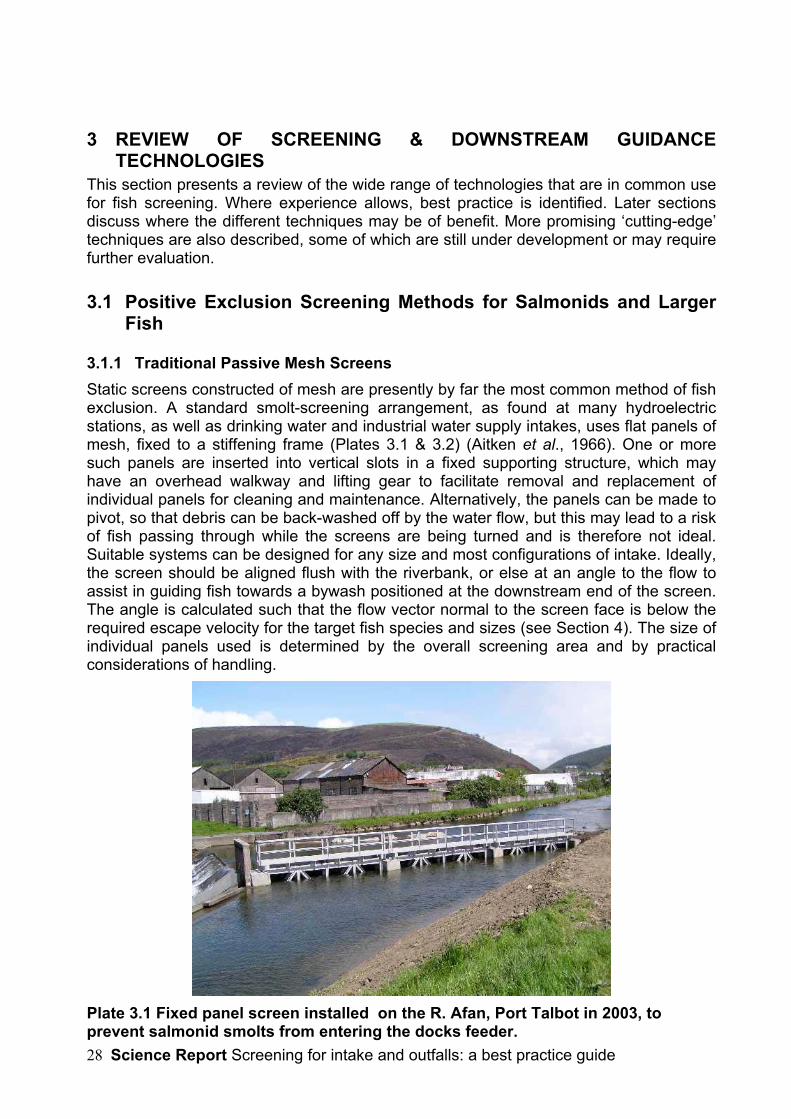
3.1.1 Traditional Passive Mesh ScreensStatic screens constructed of mesh are presently by far the most common method of fishexclusion. A standard smolt-screening arrangement, as found at many hydroelectricstations, as well as drinking water and industrial water supply intakes, uses flat panels ofmesh, fixed to a stiffening frame (Plates 3.1 & 3.2) (Aitken et al., 1966). One or moresuch panels are inserted into vertical slots in a fixed supporting structure, which mayhave an overhead walkway and lifting gear to facilitate removal and replacement ofindividual panels for cleaning and maintenance. Alternatively, the panels can be made topivot, so that debris can be back-washed off by the water flow, but this may lead to a riskof fish passing through while the screens are being turned and is therefore not ideal.Suitable systems can be designed for any size and most configurations of intake. Ideally,the screen should be aligned flush with the riverbank, or else at an angle to the flow toassist in guiding fish towards a bywash positioned at the downstream end of the screen.The angle is calculated such that the flow vector normal to the screen face is below therequired escape velocity for the target fish species and sizes (see Section 4). The size ofindividual panels used is determined by the overall screening area and by practicalconsiderations of handling.
Plate 3.1 Fixed panel screen installed on the R. Afan, Port Talbot in 2003, toprevent salmonid smolts from entering the docks feeder.
Science Report Screening for intake and outfalls: a best practice guide 29
The mesh can be made from one of a number of materials, including plastics butstainless steel is the norm. The ease of cleaning and extended life expectancy outweighthe initially higher capital costs. Weldmesh is easier to clean and cheaper to producethan e.g. a woven mesh. Plastic meshes, used on the band- or drum-screens of somecontinental power stations, are probably not sufficiently robust for use in open water.Stainless-steel wedge-wire is very effective, particularly where it is required to excludejuvenile fish also (see section 3.2.2). The amount of debris reaching the fish screen maybe lessened by placing a coarser trash rack in front of it, without affecting fish passage.In this case a bywash entrance must also be provided upstream of the trash rack as wellas by the smolt screen, so that larger fish (e.g. kelts) can bypass the structure. Anexample of this is found at Scottish Hydroelectric’s Dunalastair Dam (see Aitken et al.,1966). Alternatively, a larger bar spacing can be used (e.g. 15 cm) or gaps can be left atintervals to allow larger fish to pass.
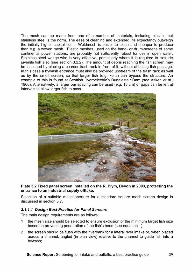
Plate 3.2 Fixed panel screen installed on the R. Plym, Devon in 2003, protecting theentrance to an industrial supply offtake.Selection of a suitable mesh aperture for a standard square mesh screen design isdiscussed in section 5.7.
3.1.1.1 Design Best Practice for Panel ScreensThe main design requirements are as follows:1 the mesh size should be selected to ensure exclusion of the minimum target fish size
based on preventing penetration of the fish’s head (see equation 1);2 the screen should be flush with the riverbank for a lateral river intake or, when placed
across a channel, angled (in plan view) relative to the channel to guide fish into abywash;
Science Report Screening for intake and outfalls: a best practice guide30
3 a suitable bywash should be provided where the screen is placed across thechannel;
4 the velocities ahead of the screen should be low enough to allow fish to escapewithout injury.
For shallow water applications (typically <1 m), it may be practicable to operate fixedscreens with manual raking or brushing. For deeper water designs, screens will need tobe removable for cleaning. For this purpose they are normally dropped into vertical slotsfrom which they can be hoisted out for cleaning. In this case best practice will alsoinclude:
• provision of two sets of slots, one behind the other, allowing a cleaned screen tobe inserted before the soiled screen is removed;
• provision of adequate seals around the screen to prevent fish passage or injury;
• provision of a datum mark on the screen which aligns with a mark on the slot railsto show when the screen is fully seated and sealed.
3.1.1.2 ApplicationsPassive mesh panel screens are suitable for a wide range of applications provided thatthe above criteria are met. Limiting factors may include required frequency of cleaning inorder to avoid risk of blockage, structural strength in relation to flood damage risk andhydraulic head loss where small mesh sizes are used. These factors tend to becomemore significant with larger abstraction flows. Factors favouring this type of screeninclude no necessity for electrical power and relatively low capital cost, especially onsmall installations.
3.1.1.3 Fish Species/Life StagesSuitable for all fish species and life stages, subject to meeting design requirements 1-4above.
3.1.1.4 Ease of retrofittingRetrofitting of this type of screen is possible but depends largely on site characteristics. Acommon problem with retrofitting fixed fish screens as a replacement for simple trashracks is that water velocities may be too high. In this case it may be necessary to widenor deepen the intake.
3.1.2 Vertical or Inclined Bar RacksVertical or inclined bar screens have in the past been used mainly as trash racks fordebris exclusion; many are fitted with moveable tines or raking systems that keep thescreens clear of rubbish. Back- and front-raked systems are available, but the formernecessarily lack horizontal braces and are not recommended for closely-spaced bars.Conventional trash rack spacings may be anywhere between 38 mm and 150 mm,depending on the application. Inclining the bars by 10o to the vertical assists inmaintaining the weight of the rake against the bars. Mild steel (with or withoutgalvanization) is commonly used as the construction material, or stainless steel. Onenorth-American manufacturer4 offers robust plastic trash racks.
4 (Structure Guard Inc., Maine, USA www.structureguard.com )

Science Report Screening for intake and outfalls: a best practice guide 31
Currently there is interest in replacing two-tier systems comprising trash racks followedby mesh fish screens with a single-tier bar rack using a smaller bar spacing that can actas a fish screen. This provides a self-cleaning alternative to the traditional manuallycleaned mesh panel screen described above. Scottish and Southern Energy plc (SSE)have been investigating this approach for a number of years. Clough et al. (2000unpublished) undertook controlled trials in a test flume constructed within a large fishpass at Gaur (R. Tummel system), in which hatchery smolts were released upstream oftest bar racks of 10 mm or 12.5 mm spacings. The aim was to assess whether the risk tofish was any different when compared with a regular 12.5 x 25 mm steel mesh screen.The screens were presented either at 75o or parallel to the flow and provided with anadjacent bywash at approach velocities of up to 0.4 ms-1; bywash entrance velocitieswere 1.5 times the approach velocity. Fish reactions were observed by video camera,using infra-red lighting at night. It was concluded that:
• there was no evidence that 10 or 12.5 mm spaced bar screens were any morelikely to impinge smolts than the 12.5 x 25 mm mesh traditionally used: no fishwere impinged on either type during the tests;
• smolt behaviour was similar for both screen types, irrespective of screenalignment and whether light or dark, at all velocities tested.
Plate 3.3 Experimental apparatus used in bar rack trials at Gaur (Clough et. 2000).In 2001, SSE installed vertical bar screens at a small hydroelectric intake. Bars werespaced at 12 mm and cleaned automatically by a raking machine once a specifiedpressure differential was measured across the screen. This has performed satisfactorily,except under extreme flow conditions when the raking system has been hampered bygravel shoals accumulating at the base of the screens (Dr Alasdair Stephen, SSE,

Science Report Screening for intake and outfalls: a best practice guide32
personal communication. SSE plans to install a raked bar screen for smolt exclusion onone of its larger schemes in 2004.Other UK examples of automatically raked bar screens designed specifically for fishexclusion include a pair of screens with 10 mm spacings located at a small (2 m3s-1)hydroelectric intake at Dolanog on the R. Vyrnwy in Wales, and a larger 15 m3s-1
capacity smolt screen at Innogy Hydro’s recently refurbished Stanley Mills plant on the R.Tay (Perthshire). The Dolanog screens (New Mills Hydro Ltd) have individualhydraulically powered rakes; the river does not contain migratory fish at the abstractionand the screens are aimed primarily at excluding brown trout. The Stanley screen is alarge angled bar rack, some 33 m long and 2.4 m deep, with a single travelling rakesupported on an overhead rail. It was installed in 2003 and is intended primarily toprotect the Tay salmon run.
3.1.2.1 Design Best PracticeThe main design requirements are as for mesh screens, but in this case the bar spacingshould be set to prevent the penetration of the fish’s head. It should be noted thatequation 1 is based on penetration of a square or rectangular opening and may not beaccurate for calculating bar spacing. Rectangular section bars or perforated plates arepreferable to round-section bars, which are prone to ‘gill’ fish.While conventional design practice demands that bar spacing should be calculated inthis way for the target fish, smaller fish will not necessarily pass through screens thathave spacings exceeding the fish’s body width. Travade and Larinier (2001), whoinvestigated a bywash adjacent to a 25-mm-spaced vertical bar screen at St Cricqhydroelectric plant in France, estimated that >90% of salmonid smolts were successfullydiverted into the bywash even though they were small enough to pass through thescreen. The screen in this case was aligned perpendicular to the flow, which is notrecommended in practice, but the width of the channel was small (11m) so that fishreadily found the outlet.Angled bar racks are used quite widely on small hydroelectric plants in north America butSimmons (2000) noted that their performance has rarely been examined. He reported astudy of the bypass efficiency of an angled bar rack at the Lower Saranac HydroelectricProject at Plattsburgh New York, which also used 25 mm spacings. In this case the rackwas aligned at 45o to the flow (in plan). In an experiment in which 52 Atlantic salmonsmolts were released upstream, 29 passed the Project; none passed through the trashrack. Of 23 steelhead trout (Oncorhynchus mykiss) passing the Project in a similarexperiment, 3 (13%) passed through the trash racks. These results were obtained underthe optimal conditions tested, in which high bywash entrance velocities were maintained(≥1 ms-1, cf. velocity perpendicular to the screens of ≤0.6 ms-1). Both this and the Frenchstudy mentioned above emphasise the importance of good hydraulics and bywashattraction flow in achieving high bypass efficiencies with over-spaced bar screens. Theseaspects are discussed further in Section 4. Where over-spaced racks are used,observational trials will be needed to check efficiency.Solomon (1991) referred to the possible ‘louvre-screen’ effect of trash racks placedtangential to the main channel flow; the implication of this is that vortices generated byflow hitting the bars will act as a deterrent to fish. Unfortunately, this is not consistent withthis author’s (AWHT) observations of flow at tangential trash racks, where the dominantflow at the trash rack face during periods of abstraction tends to be near-parallel to thebars.
Science Report Screening for intake and outfalls: a best practice guide 33
Additional points in bar rack design are:
• inclining the screen by 10o to the vertical facilitates raking;
• the bars need to be sufficiently stiff to maintain the design spacing throughout thescreen; this may require horizontal tie-bars to be fixed across the back of thescreen;
• manual raking of bar screens is probably only safe and practicable in water depthsof <1.0-1.2 m
3.1.2.2 ApplicationsVertical bar racks can be considered a suitable alternative for most applications thatwould otherwise use mesh screens.
3.1.2.3 Fish Species/Life StagesVertical bar racks are potentially suitable for screening most fish, subject to the barspacing being small enough to exclude them. At present the UK user base for this type ofscreen is quite restricted and therefore there has been little feedback on the relativeperformance with different species. It could be expected that eels and other anguilliformspecies would tend to get trapped lengthwise between the bars but this is purelyspeculative. There is evidence also that eels, when confronted with a bar screen, try toforce their way through, rather swimming along the face of them (Richkus, 2001).
3.1.2.4 Ease of retrofittingRetrofitting issues are similar to those for fixed panel screens.
3.1.3 Rotary Disc Screens
3.1.3.1 Description of ScreensRotary disc screens were originally designed for the use in sewage treatment works butmay also be applied to intake screening. They are based on a series of plastic, stainlesssteel or high impact glass-reinforced polypropylene discs stacked in a column withspacing between the discs suitable for its specific usage, such as preventing theentrainment of fish or other debris. The discs within each column rotate in the samedirection with adjacent columns interleaving. The discs are driven via motors with thedirection of rotation matching that of the direction of water flow. Debris and fish will bepassed from one column to another until carried away by the flow. There is also apossibility that vibration of the discs may discourage fish to enter the area but this hasnot been investigated (Turnpenny, 1998).
Within the UK Mono Pumps Limited5 produce Discreens with apertures of 2.5, 5, 9, 13and 18mm. They have a capacity range of 0-3.7m3s-1 in depth ranges of 200 to 1750mm. The screens are fitted with comb bars to eject screened solids back into the mainflow.There have been numerous rotary disc screen installations throughout the UK over thepast decade with only one or two being used for fish intake screening applications,
5 Mono Pumps Ltd. – Martin Street, Audenshaw, Manchester, M34 5JA (0161 339 9000).
www.mono-pumps.com

Science Report Screening for intake and outfalls: a best practice guide34
others being mainly in water and sewage treatment applications. One at Testwood rawwater intake, Hampshire (Mr R. Edbury and Mr M. Bridges, Southern Water Services Ltd,personal communication) comprises four disc columns per screen unit. The units areapproximately 1 x 1.2m in area and have a handling flow rate of 40MLd-1 (0.46 m3s-1)with an approach velocity of 0.35 m.s-1. The screens were designed to prevent theentrainment of smolts and have a gap size of 9mm. The installation was completed in1997 at a cost of £200k; the installation still consists of the same number of unitsalthough one has been rebuilt during this time. The power consumption is fairly low at 4.4kW resulting in relatively low operating costs. The screens have experienced someproblems with weed becoming wrapped around the spindles of the disc, which hasresulted in the need for periodic removal and refurbishment of the screens.An upgrade at the Knapp Mill WTW by Bournemouth and West Hampshire Waterresulted in the update of the existing drum screens with six Mono L series Discreens.The Discreens are designed to prevent entrainment of both debris and aquatic wildlife.Four fourteen shaft screens were placed on the lagoon intake and two ten shaft screenson the upper intake. The screens have a handling flow of 0.76 m3s-1 and a powerconsumption of 3.7 and 4.4 kW. The screen is believed to benefit from self-cleaningabilities.
Figure 3.2 Schematic of Rotary Disc Screen
3.1.3.2 Design Best PracticeFor any single unit there is a maximum screen depth of 1m. This can be overcome forgreater depths via stacking units in a stepped format.

Science Report Screening for intake and outfalls: a best practice guide 35
Plate 3.4 Rotary Disk Screen at Testwood Raw Water Intake, R. Test, Hants
3.1.3.3 ApplicationsThe screen is suitable primarily for the screening of smolts and larger fish on rivers with astrong sweeping flow. High leaf and filamentous/stranded weed loads may causeproblems. This screen is not economical for large intakes owing to the high surface arearequired to achieve low approach velocities, and consequent high costs.
3.1.3.4 Fish species/life stagesDepending on the spacing between discs this screen should be suitable for screeningsalmonid smolts and adults of most species.
3.1.3.5 Ease of RetrofittingThe main attraction of the rotary disc screen is that it is compact and a relativelystraightforward retrofit option. It may, as at Testwood, be suitable as a direct replacementfor trash racks, provided that these are flush with the riverbank or projecting out into theflow. It can also serve as a replacement for drum screens as at the Knapp Mill WTW.Approach velocities need to be set according to the species and sizes of fish involved.
3.1.4 Spillway ScreensThe principle of a spillway screen is that a grid of some sort replaces part of thedownstream face of a weir and water falling through the grid enters a channel beneath,from which it is conveyed to the turbine or other application. Meanwhile, fish and debrislarger than the screen openings are flushed by surplus flow across the surface of the gridto the downstream side of the weir (Turnpenny, 1998).
3.1.4.1 Coanda ScreenThe Coanda screen is based on the ‘Coanda-effect’, the principle of how fluids follow asurface, a phenomenon first identified by Henri-Marie Coanda in 1910. In this case thesurface is that of a wedge-wire screen with the bars running from side to side across thewidth of the weir (Figure 3.3, Plates 3.4, 3.5). Water then follows the surface of the V-profile wires and runs into the collecting chamber (penstock) below. The wedge-wire
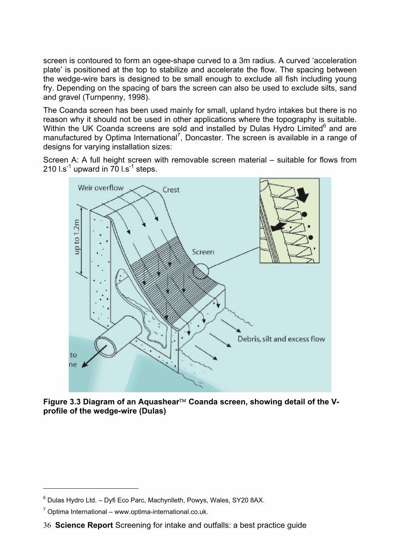
Science Report Screening for intake and outfalls: a best practice guide36
screen is contoured to form an ogee-shape curved to a 3m radius. A curved ‘accelerationplate’ is positioned at the top to stabilize and accelerate the flow. The spacing betweenthe wedge-wire bars is designed to be small enough to exclude all fish including youngfry. Depending on the spacing of bars the screen can also be used to exclude silts, sandand gravel (Turnpenny, 1998).The Coanda screen has been used mainly for small, upland hydro intakes but there is noreason why it should not be used in other applications where the topography is suitable.Within the UK Coanda screens are sold and installed by Dulas Hydro Limited6 and aremanufactured by Optima International7, Doncaster. The screen is available in a range ofdesigns for varying installation sizes:Screen A: A full height screen with removable screen material – suitable for flows from210 l.s-1 upward in 70 l.s-1 steps.
Figure 3.3 Diagram of an Aquashear Coanda screen, showing detail of the V-profile of the wedge-wire (Dulas)
6 Dulas Hydro Ltd. – Dyfi Eco Parc, Machynlleth, Powys, Wales, SY20 8AX.7 Optima International – www.optima-international.co.uk.

Science Report Screening for intake and outfalls: a best practice guide 37
Plate 3.5 Example of a Screen A Coanda installation (Dulas Hydro)Screen B: A full height one piece small screen – suitable for flows of 80, 100, 120, 140and 160 ls-1.Screen C: A half height full width one piece screen – suitable for flows from 100ls-1
upwards in steps of 50 ls-1.Screen D: A half height, one-piece small screen:- suitable for flows of 20, 30, 40, 50 and60 ls-1.
Plate 3.6 Example of a Screen B Coanda installation (Dulas Hydro)
Full height screens have a head loss of 1,270 mm and half height screens have a705mm head loss. Thus there must be a minimum of 705 mm sacrificable head lossavailable before a Coanda screen can be used. The maximum flow of the screens isdependent on the weir width. A full-height screen has a capacity of 140 ls-1 per metrewidth, therefore 1 m3 flow would require a weir just over 7 m in length.The recommended screen materials are 304 stainless steel in freshwater, or 316 gradefor marine environments. The acceleration plate is a circular arc similar to a parabolic‘ogee’ shape, which matches the path of an unsupported jet of water. The plate acts tospeed up the water, helping the shearing effect, which improves abstraction efficiency.

Science Report Screening for intake and outfalls: a best practice guide38
Coanda screens are designed to be low maintenance although during low flows somedebris build up may occur, which will be washed off in subsequent high flow periods.Brushing with a stiff broom clears the majority of any remaining debris. Most screensrequire periodic visual checks and brushing approximately quarterly.There was a reported total of 22 Coanda screen installations within the UK by 2003.Most are at small-scale private hydropower installations with capacities ranging from 10to 1,300 ls-1. One of the larger installations was commissioned by Innogy Hydro southwest of Fort Augustus in the Scottish Highlands. The screen is a full height design with aflow capacity of 1300 l.s-1. Although there were initially some concerns over fouling byalgae it has been found that the screen self-cleans during periods of high flow and theoverall opinion of the screen at this location is good (personal communication W.Langley).The effectiveness, suitability and cost benefit of the screen was evaluated at a smallhydropower scheme near Keswick in Cumbria (Howarth, 2001). A screen with 1mm barspacings was commissioned in April 1999. It was capable of excluding all debris greaterthan 1mm and 90% of particles >0.5mm. Performance evaluation was carried out over a15 month period with monitoring of screen capacity, silt exclusion performance, selfcleaning operation, slime and algae growth, operation and maintenance requirements,integrity and resistance to damage and cost benefit analysis. After the 15-month periodthere were no noticeable signs of wear and at high flows up to 94% of suspended siltparticles between 0.41 and 1.17mm. There had been no records of blockages by debrisalthough it was believed that very thin strands of weed may pass through the wedge-wires. After the 15 months, a thin film of algae had developed over the screen, resultingin some loss of capacity, although it was readily cleaned with a stiff brush. Overall thescreen was found to be consistently robust, resistant and has a high performance rating.Fish Protection PerformanceNo assessment of fish exclusion efficiency or fish condition after passing the screen wasundertaken in the Keswick study. Elsewhere, Bestgen (2000) reported tests carried outat the Colorado State University Larval Fish Laboratory on the exclusion and survivalrates of fathead minnow passing over a Coanda screen. Out of 150 trials releasing andrecapturing fish downstream of five different lengths (5, 7.5, 12.5, 22.5 and 45mm) anexclusion rate of “nearly 100%” was obtained for fish greater than 12.5mm.
3.1.4.2 The ‘Smolt Safe’ ScreenThe Smolt Safe screen (Figure 3.4) is manufactured by Rivertec of East Sussex. Theprinciple is broadly similar to that of the Coanda-effect screen. In the configurationshown, the weir is constructed flush with the bank of the river and water is carried offsideways from below the screen. Water falling through the screen is collected in a take-off channel, while a further debris channel is provided to carry fish and trash back to theriver. There is no reason, however, why the screen should not be constructed as part ofa transverse weir, as in the Coanda-effect example.The example shown in Figure 3.4 was constructed at a distillery where there is a largeamount of waterborne debris. Screen mesh size in the example is 10 mm, but this can bevaried as required. The manufacturers claim the screen to be 100% safe for passage ofsmolts and other fish but this has not been verified by trials. A similar screen built atHeltondale in Cumbria has been found not to be suitable for screening pre-smolts (G.Armstrong, personal communication. The problem was due to fish becoming trappedamong debris at times when there was insufficient washover flow. Potentially, this can be
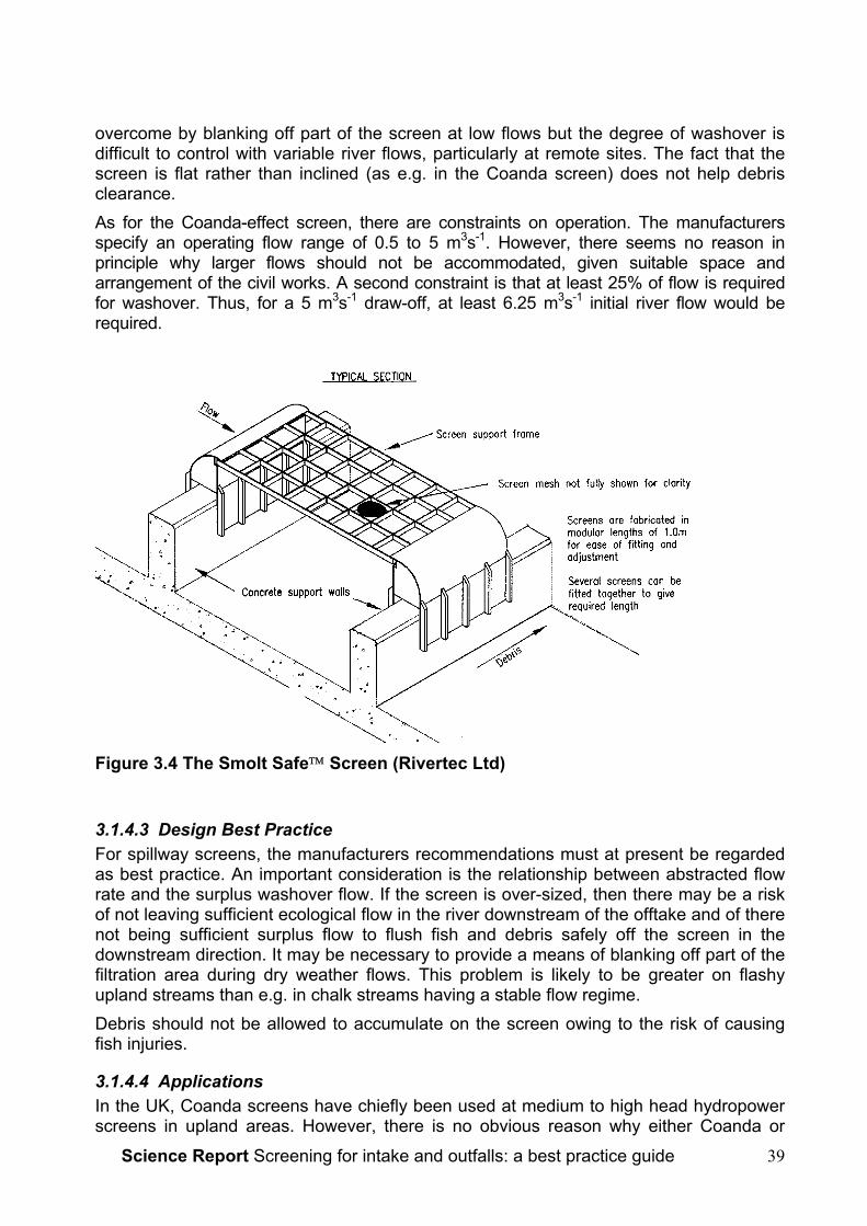
Science Report Screening for intake and outfalls: a best practice guide 39
overcome by blanking off part of the screen at low flows but the degree of washover isdifficult to control with variable river flows, particularly at remote sites. The fact that thescreen is flat rather than inclined (as e.g. in the Coanda screen) does not help debrisclearance.As for the Coanda-effect screen, there are constraints on operation. The manufacturersspecify an operating flow range of 0.5 to 5 m3s-1. However, there seems no reason inprinciple why larger flows should not be accommodated, given suitable space andarrangement of the civil works. A second constraint is that at least 25% of flow is requiredfor washover. Thus, for a 5 m3s-1 draw-off, at least 6.25 m3s-1 initial river flow would berequired.
Figure 3.4 The Smolt Safe Screen (Rivertec Ltd)
3.1.4.3 Design Best PracticeFor spillway screens, the manufacturers recommendations must at present be regardedas best practice. An important consideration is the relationship between abstracted flowrate and the surplus washover flow. If the screen is over-sized, then there may be a riskof not leaving sufficient ecological flow in the river downstream of the offtake and of therenot being sufficient surplus flow to flush fish and debris safely off the screen in thedownstream direction. It may be necessary to provide a means of blanking off part of thefiltration area during dry weather flows. This problem is likely to be greater on flashyupland streams than e.g. in chalk streams having a stable flow regime.Debris should not be allowed to accumulate on the screen owing to the risk of causingfish injuries.
3.1.4.4 ApplicationsIn the UK, Coanda screens have chiefly been used at medium to high head hydropowerscreens in upland areas. However, there is no obvious reason why either Coanda or

Science Report Screening for intake and outfalls: a best practice guide40
Smolt Safe screens should not be used for other types of application where sufficienthead of water exists, e.g. fish farms located on upland rivers.
3.1.4.5 Fish Species/Life StagesAlthough used in this country mainly for trout and salmon exclusion, spillway screenswould be equally suitable for exclusion of eels, lampreys and other upland river species.The sizes of fish excluded would depend on the wire spacings but, for example, a ≤3mmspacing should be suitable for salmonid fry exclusion.
3.1.4.6 Ease of RetrofittingCoanda or Smolt-safe screens are likely to be suitable mainly for new-buildapplications or replacement of existing spillway screens.
3.1.5 Band or Drum Screens Modified for Fish ReturnMany power stations intakes and potable water abstractions are fitted with mobile bandscreens or drum screens for debris filtration. These are usually set somewhere within thepumphouse and not at the intake point. Fish-handling modifications have beendeveloped for both types which can reduce the risk of injury, at least to the more robustspecies. The modifications relate chiefly to the design of the ledges or ‘buckets’ whichare used to lift fish and debris out of the water, and to reduced-pressure backwashsprays that are used to flush material off the screens and out of the buckets. Thereafter,instead of discharging the filtered material into trash baskets for disposal, a return gullyor pipeline puts them back into the water body. Such a system is commonly known as a‘fish return’ or ‘fish rescue’ system.Fish return systems have been used at power stations in the UK for many years. Theearliest ones were constructed at CEGB estuarine sites in the 1960s for the return ofsalmon (Salmo salar) and sea trout (S. trutta) smolts (e.g., Uskmouth andOldbury-on-Severn power stations) but for various reasons these were never fully utilisedor evaluated. A number of other stations (e.g. Dungeness 'B', Sizewell 'A') have operatedsimple trash return systems which involve periodic discharge to the sea of the biologicaland other debris that has accumulated in trash baskets, with no deliberate attempt topromote the survival of living organisms; in fact, the system at Sizewell ‘A’ macerates thedebris prior to discharge. Sizewell 'B' power station incorporate a facility to direct trasheither to baskets or into the CW discharge, along with a number of other engineeringmeasures to reduce stress effects on fish. The Sizewell ‘B’ system is licensed to operatein fish-return mode, provided that quantities of fish are below a certain level, otherwisefish must be collected in trash baskets to avoid possible wash-up of dead fish (notablysprats) on beaches. Barking Power Station (Thames Estuary) has a fish recovery systembased on modified band screens, which returns fish to the estuary via the cooling wateroutlet.Fish return is practiced widely overseas. In the United States, the prospect ofcompensation being levied against fish losses and the requirement under Section 316(b)of the Federal Water Pollution Control Act to implement effective environmentalprotection systems has encouraged the development of fish return systems. In Europe,the French power industry, as part of its nuclear expansion during the '70s and '80s,investigated a wide range of fish protection systems and has implemented a fish andshrimp recovery system on at least one estuarine site, Le Blayais, on the Gironde(Travade et al., 1983). A new power station at Doel in Belgium is also being fitted with a
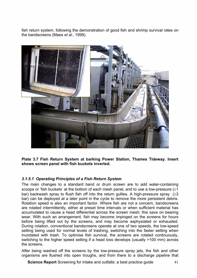
Science Report Screening for intake and outfalls: a best practice guide 41
fish return system, following the demonstration of good fish and shrimp survival rates onthe bandscreens (Maes et al., 1999).
Plate 3.7 Fish Return System at barking Power Station, Thames Tideway. Insertshows screen panel with fish buckets inverted.
3.1.5.1 Operating Principles of a Fish Return SystemThe main changes to a standard band or drum screen are to add water-containingscoops or ‘fish buckets’ at the bottom of each mesh panel, and to use a low-pressure (≤1bar) backwash spray to flush fish off into the return gullies. A high-pressure spray (≥3bar) can be deployed at a later point in the cycle to remove the more persistent debris.Rotation speed is also an important factor. Where fish are not a concern, bandscreensare rotated intermittently, either at preset time intervals or when sufficient material hasaccumulated to cause a head differential across the screen mesh; this save on bearingwear. With such an arrangement, fish may become impinged on the screens for hoursbefore being lifted out by the screens, and may become asphyxiated or exhausted.During rotation, conventional bandscreens operate at one of two speeds, the low-speedsetting being used for normal levels of trashing, switching into the faster setting wheninundated with trash. To optimise fish survival, the screens are rotated continuously,switching to the higher speed setting if a head loss develops (usually >100 mm) acrossthe screens.After being washed off the screens by the low-pressure spray jets, the fish and otherorganisms are flushed into open troughs, and from there to a discharge pipeline that

Science Report Screening for intake and outfalls: a best practice guide42
returns them to the water. Handling stress is minimised in these stages through carefuldesign and construction of the gulleys and pipes, ensuring that tight bends are avoidedand that smooth surfaces are provided. Swept bends are used throughout with eitherstainless steel, fibre-glass or PVC materials, with joints ground smooth. Therecommended radius for swept bends is 3 m when a trough or pipe diameter of ≤0.3 m isused (Turnpenny et al., 1998), although space constraints do not always allow this.Where smaller-radius bends are used, fish tend to find shelter and epibenthic species inparticular may accumulate; also, tight bends are susceptible to blockage, hence accessfor cleaning is required. Where larger pipe or trough diameters are used (≥0.4 m), thebend radius may be reduced to ≥1.5 times the pipe diameter, as there will be less risk ofblockage. The chief requirements are that blockage and hold-up of debris should beavoided and that access for maintenance should be provided in case of blockage. Thescreen wash pumps supply flow for the backwash sprays to ensure that the fish are keptmoving through the system and to reduce the risk of blockage.The use of chlorine or other biocides can, potentially, reduce survival in fish returnsystems. Fortunately, in the UK, typically 80% of the annual fish take occurs outside theseason (approximately May–September, or when water temperature is >9oC) whenbiocides are applied. The toxicity of chlorine, the most common biocide used at powerstations, depends on the concentration and the exposure time. For biofouling controlpurposes, chlorine is normally injected in the intake at around 1 mgL-1, decaying to about0.2 mgL-1 at the CW pumps. The exposure time in the intake forebay and screenwell canbe kept to an hour or less in a purpose-built system. The toxic risk is generally low underthese conditions. However, unless a detailed analysis of the toxic risk can beundertaken, taking into account the local water quality conditions, mixing dynamics andspecies and life-stages exposed, it is preferable to ensure that chlorine is injecteddownstream of the screens.
3.1.5.2 Fish Protection PerformanceThe survival rates of the returned fish can depend on a number of design and operationalfactors. Design variations revolve mainly around the shape and construction material ofthe fish buckets and the backwash arrangements. Older designs often had incorrectbucket geometry, so that fish fell back into the water and were recycled several times orwere not washed out from the optimum point of the cycle. Table 3.1 shows the typicalsurvival rates measured at older fish return systems, ranging from >80% for robustepibenthic species to virtually nil for delicate pelagics.

Science Report Screening for intake and outfalls: a best practice guide 43
Table 3.1 Typical fish survival reported from studies of drum-or bandscreens withsimple modifications for fish return (e.g. with fish buckets, low-pressure spraysand continuous screen rotation) (Turnpenny, unpublished data).
Fish Group Survival Rate >48 h AfterImpingement
PELAGICe.g. herring, sprat, smelt <10%
DEMERSALe.g. cod, whiting, gurnards,etc
50-80%
EPIBENTHICe.g. flatfish, gobies,rocklings, dragonets, etc.,and crustacea
>80%
In the USA, requirements to reduce fish impingement mortalities have led to renewedresearch into fish return techniques. Recent developments have benefited in particularfrom the use of CFD flow analysis to optimize the fish bucket design, which can greatlyimprove the fish retention and reduce damaging turbulence. There have also beenimprovements resulting from use of non-metallic buckets, smoother screening materialsand improved methods of washing off the fish. One company (Beaudray USA) claims toimprove fish survival by removing fish before the screen lifts them out of the water. It isnow claimed to be possible to return >90% of even delicate pelagic species alive.
3.1.5.3 Design Best PracticeWith recent developments in the USA, this is clearly an area where improved designsshortly may become more widely available. Some of the innovations are likely to beprotected by patents and therefore available only through certain screen manufacturers.It is important when specifying band or drum screens which are to be used for fish returnto ensure that the design of the fish buckets in particular has been optimized for fishhandling and evidence of this should be sought from the manufacturer. Other key pointsin fish return system design are:
• The screens should be capable of long-term continuous operation: intermittentoperation is unsuitable for fish return. This means, in particular, that bearing lifeshould be considered.
• The screen meshes should be smooth and ‘fish-friendly’. Certain types of wovenstainless mesh are commonly used for this purpose.
• The mesh size should be as small as is practical, and of no more than 6 mmaperture.
• Low-pressure backwash sprays (≤1bar) should be used for fish removal; higherpressure jets may be used at a later point in the cycle to wash off debris.

Science Report Screening for intake and outfalls: a best practice guide44
• The geometry of the collecting hoppers should be checked to ensure that fish thatare washed off the screens cannot fall back into the screenwell (an issue mainlyon drum screens).
• Biocides should be applied downstream of the screens unless it can be shownthat the toxic risk is negligible.
• Fish return gullies should be smooth, with any joints properly grouted and finished.They should be a minimum of 0.3m diameter; 0.5m diameter or larger is preferredfor long runs (>30m).
• It is beneficial to enclose or cover fish return lines to avoid algal growth. Suitableaccess hatches or rodding points should be provided to facilitate maintenance.
• Where bends are required, swept bends of radius >3m should be used.
• Dedicated fish return lines which discharge well blow the low water mark arepreferred. Return on power plants via the heated water discharge should only beused where it can be demonstrated that survival rates will be acceptable.
• A continuous washwater supply should be provided that will ensure sufficientdepth to keep fish immersed and moving along the return line.
• At coastal sites where there is a risk of occasional inundation by schools ofpelagic fish, provision may need to be made for diverting the catch to collectingbaskets. This can be necessary to avoid the risk of discharging large quantities ofdead fish onto neighbouring bathing beaches.
Plate 3.8 A sharp bend in this fish return gulley demonstrates the issue ofbiofouling where uneven joints have encouraged algal growth, causing a flatfish totake cover there. A smooth surface or exclusion of light would have preventedthis.
3.1.5.4 ApplicationsFish return systems are presently used mainly at estuarine and coastal power stations,although the technique is potentially suitable for fish protection at potable water intakeswhere band screens are often used.
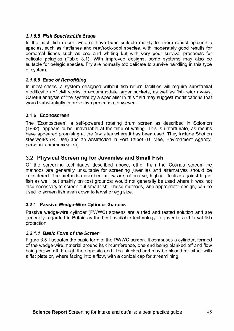
Science Report Screening for intake and outfalls: a best practice guide 45
3.1.5.5 Fish Species/Life StageIn the past, fish return systems have been suitable mainly for more robust epibenthicspecies, such as flatfishes and reef/rock-pool species, with moderately good results fordemersal fishes such as cod and whiting but with very poor survival prospects fordelicate pelagics (Table 3.1). With improved designs, some systems may also besuitable for pelagic species. Fry are normally too delicate to survive handling in this typeof system.
3.1.5.6 Ease of RetrofittingIn most cases, a system designed without fish return facilities will require substantialmodification of civil works to accommodate larger buckets, as well as fish return ways.Careful analysis of the system by a specialist in this field may suggest modifications thatwould substantially improve fish protection, however.
3.1.6 EconoscreenThe ‘Econoscreen’, a self-powered rotating drum screen as described in Solomon(1992), appears to be unavailable at the time of writing. This is unfortunate, as resultshave appeared promising at the few sites where it has been used. They include Shottonsteelworks (R. Dee) and an abstraction in Port Talbot (D. Mee, Environment Agency,personal communication).
3.2 Physical Screening for Juveniles and Small FishOf the screening techniques described above, other than the Coanda screen themethods are generally unsuitable for screening juveniles and alternatives should beconsidered. The methods described below are, of course, highly effective against largerfish as well, but (mainly on cost grounds) would not generally be used where it was notalso necessary to screen out small fish. These methods, with appropriate design, can beused to screen fish even down to larval or egg size.
3.2.1 Passive Wedge-Wire Cylinder ScreensPassive wedge-wire cylinder (PWWC) screens are a tried and tested solution and aregenerally regarded in Britain as the best available technology for juvenile and larval fishprotection.
3.2.1.1 Basic Form of the ScreenFigure 3.5 illustrates the basic form of the PWWC screen. It comprises a cylinder, formedof the wedge-wire material around its circumference, one end being blanked off and flowbeing drawn off through the opposite end. The blanked end may be closed off either witha flat plate or, where facing into a flow, with a conical cap for streamlining.

Science Report Screening for intake and outfalls: a best practice guide46
Figure 3.5 The basic form of the Passive Wedge-Wire Cylinder (PWWC) Tee-Screen (courtesy Johnson Screens)The wedge-wire material is similar to that used in the Coanda screen (Figure 3.3). Theprofile of the wire that forms the screen surface is V-shaped. In manufacture, thelongitudinal supporting bars are fixed about a mandrel, around which the vee-wire iswound in a spiral. The apex of the ‘V’ is welded onto the bars at each point of contact.The pitch of the spiral thus determines the slot-width of the screen. For someapplications, the wedge-wire screening material is deployed in the form of flat panels, butit will first have been manufactured by this method and then flattened out.The major benefits of using the V-profile wire in PWWC screens are that it offers lowhydraulic resistance for a given open area (when compared with conventional screeningmaterials), combined with low blocking risk: particles tend either to wash past the screenor to pass through the slots, as slot width increases towards the inside of the screen.
3.2.1.2 PWWC Screen ConfigurationsManufacturers offer a range of PWWC configuration options, including single, bulkheador pipe mounted units, tee-form screens and multiple groupings attached to a manifold.Figure 3.6 illustrates various typical arrangements. The arrangement used depends onthe water depth, space available and other factors, but the options available make theconfiguration very flexible. Where, for example, water is shallow, a number of small-diameter units can be used rather than a single large one.
3.2.1.3 Air Backwash SystemAlthough not fitted to all systems, PWWC screens are more often than not fitted with anair-blast backwash system, such as the Johnson Hydroburst system. In this, aperforated air discharge pipe is welded along the bottom, inside of the screen. This is fedby an air compressor and reservoir, from which explosive bursts of air (up to 10 barpressure) are released at regular intervals (e.g. daily or more often, depending on debrislevels), or else once a certain pressure differential has been measured across the insideand outside of the screen. This may be under manual or automatic control. The clearingaction is caused by the displacement of water through the slots from inside the screen
Science Report Screening for intake and outfalls: a best practice guide 47
chamber, as the air volume expands following release. Any debris that has becomepinned on the outer surface is thus lifted off and carried away by local water movement.
Figure 3.6 Examples of multiple PWWC screen arrangements. These usuallyinvolve connection to a manifold (courtesy Johnson Screens).
3.2.1.4 Construction Material and BiofoulingFor freshwater use, screens are made from stainless steel, of a grade suited to waterquality conditions. In marine and estuarine environments, stainless steel screens tend tobiofoul rapidly and a copper-nickel alloy is preferred. Bamber and Turnpenny (1986)tested the efficacy of a small 70%:30% Cu:Ni test PWWC screen at Fawley PowerStation on Southampton Water, Hampshire where the mean salinity is around 32‰. Itshowed little sign of biofouling after 15 months of operation without any cleaning otherthan the once-daily air backwash cycle. After this time the measured flow throughput wasreduced by only 2% compared with the starting figure (nominal flow rate 10Ls-1). Morerecently, an alloy of 90%:10% Cu:Ni composition has been used for estuarineapplications. A large cooling water make-up intake at Connah’s Quay Power Station onthe Dee Estuary (Cheshire) with PWWC screens constructed of this alloy has operatedcontinuously since 1996 without any need for cleaning (W. Smith, PowerGen plc,personal communication).
3.2.1.5 Fish Protection PerformancePWWC screens have a number of features that make them suitable for prevention of fishentrainment. These include the low through-slot velocity, allowing fish to swim away, therelatively smooth external presentation of the screen, which reduces the risk of fishabrasion, and the narrow slot widths available, making it possible to prevent entrainmentof fish even down to egg or larval sizes. The main reason for selecting PWWC screens inpreference to lower cost alternatives is to improve the level of protection for the smallestindividuals, i.e. egg or larval/postlarval stages (‘pinhead fry’). This aspect has beeninvestigated in North American studies (Heuer and Tomljanovich, 1979; Hanson, 1979).Conclusions of the Heuer and Tomljanovich (1979) study were:
• For very small larvae (<6.0 mm total length), a slot width of 0.5 mm and through-slot velocity of ≤7.5 cm.s-1 would be required.
• For larvae of 7-10 mm total length, a slot size of 1.0 mm and through-slot velocityof 7.5 cm.s-1 was ideal, although a through-slot velocity of 15 cm.s-1 would be lowenough for some species.
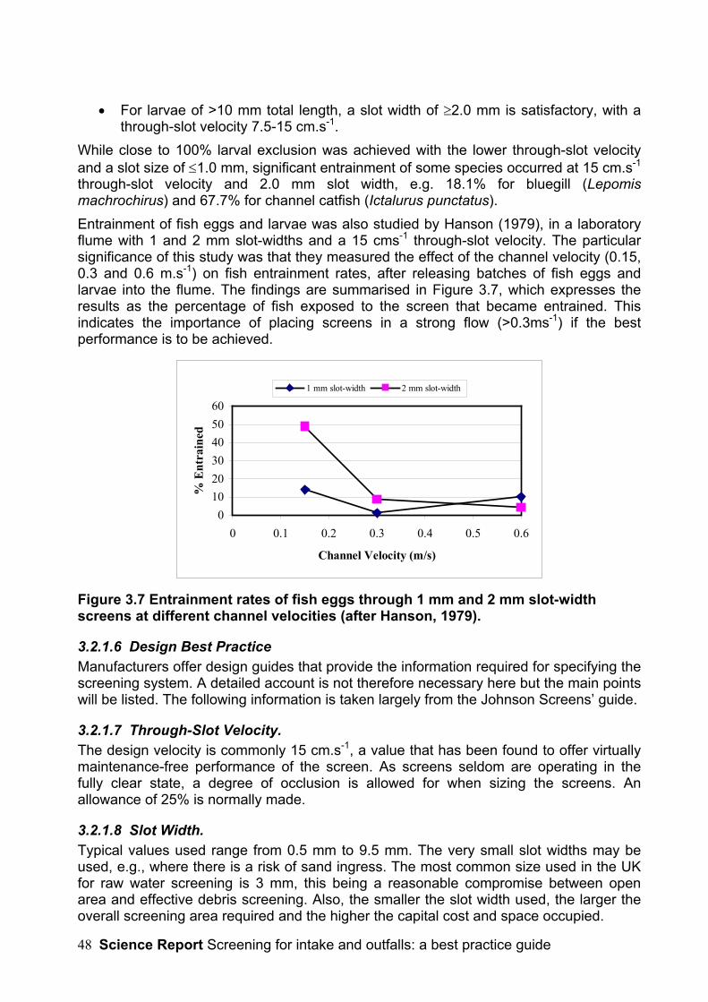
Science Report Screening for intake and outfalls: a best practice guide48
• For larvae of >10 mm total length, a slot width of ≥2.0 mm is satisfactory, with athrough-slot velocity 7.5-15 cm.s-1.
While close to 100% larval exclusion was achieved with the lower through-slot velocityand a slot size of ≤1.0 mm, significant entrainment of some species occurred at 15 cm.s-1
through-slot velocity and 2.0 mm slot width, e.g. 18.1% for bluegill (Lepomismachrochirus) and 67.7% for channel catfish (Ictalurus punctatus).Entrainment of fish eggs and larvae was also studied by Hanson (1979), in a laboratoryflume with 1 and 2 mm slot-widths and a 15 cms-1 through-slot velocity. The particularsignificance of this study was that they measured the effect of the channel velocity (0.15,0.3 and 0.6 m.s-1) on fish entrainment rates, after releasing batches of fish eggs andlarvae into the flume. The findings are summarised in Figure 3.7, which expresses theresults as the percentage of fish exposed to the screen that became entrained. Thisindicates the importance of placing screens in a strong flow (>0.3ms-1) if the bestperformance is to be achieved.
0102030405060
0 0.1 0.2 0.3 0.4 0.5 0.6
Channel Velocity (m/s)
% E
ntra
ined
1 mm slot-width 2 mm slot-width
Figure 3.7 Entrainment rates of fish eggs through 1 mm and 2 mm slot-widthscreens at different channel velocities (after Hanson, 1979).
3.2.1.6 Design Best PracticeManufacturers offer design guides that provide the information required for specifying thescreening system. A detailed account is not therefore necessary here but the main pointswill be listed. The following information is taken largely from the Johnson Screens’ guide.
3.2.1.7 Through-Slot Velocity.The design velocity is commonly 15 cm.s-1, a value that has been found to offer virtuallymaintenance-free performance of the screen. As screens seldom are operating in thefully clear state, a degree of occlusion is allowed for when sizing the screens. Anallowance of 25% is normally made.
3.2.1.8 Slot Width.Typical values used range from 0.5 mm to 9.5 mm. The very small slot widths may beused, e.g., where there is a risk of sand ingress. The most common size used in the UKfor raw water screening is 3 mm, this being a reasonable compromise between openarea and effective debris screening. Also, the smaller the slot width used, the larger theoverall screening area required and the higher the capital cost and space occupied.

Science Report Screening for intake and outfalls: a best practice guide 49
3.2.1.9 Screen Diameter and Spacing from SurfacesThe maximum screen diameter should be half the water depth at the lowest extreme ofwater level; preferably it should be no more than one-third. Where depth is shallow, theoption of using tee-configurations or other multiple arrangements of small-diameterscreens can be considered.The recommended minimum submergence depth is half the screen diameter, with thescreen being spaced an equivalent distance from the bed and any wall. Submergence tothis depth avoids the risk of excessive entrainment of surface-carried debris into theabstraction flow. Spacings from the bed and wall are to avoid debris rolling along the bedbecoming entrained, or larger items becoming jammed. Placing screens too close to thebed or wall may also compromise the uniformity of the hydraulic field around the screen.
3.2.1.10 Screen SizingThe number, types and sizes of screen units required for a given abstraction are selectedso as to satisfy the above requirements. Manufacturers’ design guides provide tablesand formulae from which requirements can readily be calculated.
3.2.1.11 Velocity of Flow Past Screen and Screen SitingThe successful clearance of debris following air backwashing is dependent on adequateambient flow past the screen, otherwise, debris may accumulate. This may be throughriver or tidal flow, or through wind-driven circulation in lakes and reservoirs. It is alsoimportant that screens are not sited in backwaters where debris naturally accumulates asa result of eddy currents.A steady current is required to ensure debris is carried away.
3.2.1.12 ApplicationsPWWC screens are suited to a wide range of flowing water applications in freshwater,estuarine and marine environments. They are best suited to smaller abstractions of a fewm3s-1 or less, as larger arrays may become cumbersome, unless space is unlimited.They are used, for example, for potable water abstractions, CCGT8 power stations andfish farm supply, but are not suitable e.g. for low-head hydroelectric generation onaccount of the very large flows involved.
3.2.1.13 Fish Species/LifestagesThey are probably suitable for excluding all species and sizes of fish given suitable wirespacings. A particularly interesting case is the study carried out by the National RiversAuthority at Moor Monkton pumping station on the Yorkshire Ouse (Frear and Axford,1991 and unpublished). Collections of impinged fish from the bandscreens were madebefore and after the fitting of PWWC screens to the intake. Between January 1990 andMay 1991, 16,022 lampreys (brook- and river-) were collected from the band screens;most were recently metamorphosed pre-adults (“transformers”), along with someammocoetes and adults. In 1995, the intakes were fitted with an array of eight JohnsonPWWC screens (model T42 with 3 mm slot-width, total capacity 3.5 m3s-1). Subsequentsurveys found virtually no lamprey or other fish impingement. The small numbers thatwere collected (around ten per week during the winter) may have passed through thescreen but could also have been ones that remained resident in the abstraction lagoon,
8 Combined-cycle gas turbine
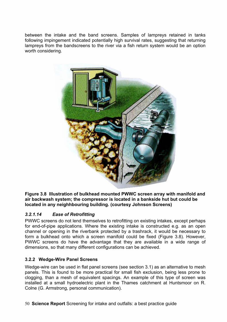
Science Report Screening for intake and outfalls: a best practice guide50
between the intake and the band screens. Samples of lampreys retained in tanksfollowing impingement indicated potentially high survival rates, suggesting that returninglampreys from the bandscreens to the river via a fish return system would be an optionworth considering.
Figure 3.8 Illustration of bulkhead mounted PWWC screen array with manifold andair backwash system; the compressor is located in a bankside hut but could belocated in any neighhbouring building. (courtesy Johnson Screens)
3.2.1.14 Ease of RetrofittingPWWC screens do not lend themselves to retrofitting on existing intakes, except perhapsfor end-of-pipe applications. Where the existing intake is constructed e.g. as an openchannel or opening in the riverbank protected by a trashrack, it would be necessary toform a bulkhead onto which a screen manifold could be fixed (Figure 3.8). However,PWWC screens do have the advantage that they are available in a wide range ofdimensions, so that many different configurations can be achieved.
3.2.2 Wedge-Wire Panel ScreensWedge-wire can be used in flat panel screens (see section 3.1) as an alternative to meshpanels. This is found to be more practical for small fish exclusion, being less prone toclogging, than a mesh of equivalent spacings. An example of this type of screen wasinstalled at a small hydroelectric plant in the Thames catchment at Huntsmoor on R.Colne (G. Armstrong, personal communication).

Science Report Screening for intake and outfalls: a best practice guide 51
North American experience is that orienting the wires vertically rather than horizontallyfacilitates cleaning, as vertical raking machines can be adapted for this purpose (S.Rainey, US National Marine Fisheries Service, personal communication). However, useof the material in the PWWC screen format is to be greatly preferred, as the air-backwash system provides a very effective cleaning mechanism; air backwashing cannotbe used in a vertical flat screen layout, as the air needs to rise through the gaps betweenthe wires.
3.2.3 Sub-Gravel Intakes and WellsSolomon (1992) discussed the applications of sub-gravel intakes and wells, since whenthere has been no real change in the approach. A brief summary of these technologiesand examples is included here for completeness.Sub-gravel intakes use the riverbed itself as a screen by abstracting the water fromunderneath the bed or from an aquifer. This system also has the advantage of naturalfiltration reducing treatment costs but has the drawback of there being an extremelylimited number of suitable locations.An example of this form of abstraction is found at Ibsley on the Hampshire Avon. Anabstraction of 0.57 m3s-1 is taken via 4 streams. A wedgewire screen with 8mm slot widthis supported over a concrete chamber over which layers of gravel are placed up to theoriginal bed level. A geomembrane sheet is placed between gravel layers and gravelcleanliness is maintained by backwashing.Littlehampton abstraction uses a 4 m diameter collector well reaching down to bedrock at10m below the riverbed. 12 lateral perforated pipes extend from the well at 2 depths. Theabstraction licence granted to the well is for 0.28 m3s-1 and is anticipated to benefit fromboth high fish protection and partial water treatment (Solomon, 1992).
3.2.3.1 ApplicationsThis technique is only feasible for small abstractions in fast-flowing, eroding-substraterivers and is suitable e.g. for potable water or fish-farm supply.
3.2.3.2 Fish Species/ Life StagesThe technique should prevent the entrainment of any fish present. It may be conjecturedthat the requirement to backflush periodically could affect the habitats of lithophilousfish/lifestages, e.g. bullheads, stone loaches or juvenile salmonids, but probably over aninsignificant area.
3.2.3.3 Ease of RetrofittingThis is unlikely to be a method suitable for retrofitting in many circumstances.
3.2.4 Microfiltration BarriersThe Marine Life Exclusion System (MLES™), developed in the USA and patented byGunderboom Inc.9 is a new microfiltration barrier that is presently being tested widely inthe USA for fish exclusion at power plant intakes. It is specifically intended to provide
9 Gunderboom, Inc., 10 Hickman Dr., Sanford, Florida 32771 USA
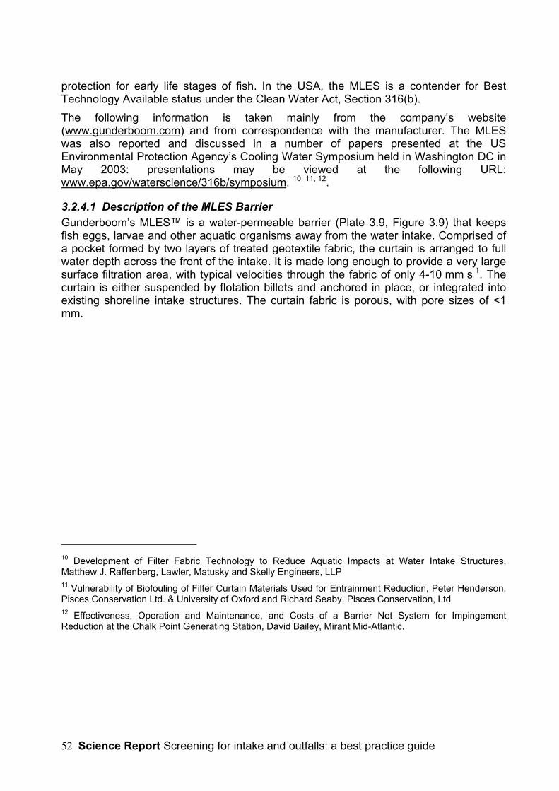
Science Report Screening for intake and outfalls: a best practice guide52
protection for early life stages of fish. In the USA, the MLES is a contender for BestTechnology Available status under the Clean Water Act, Section 316(b).The following information is taken mainly from the company’s website(www.gunderboom.com) and from correspondence with the manufacturer. The MLESwas also reported and discussed in a number of papers presented at the USEnvironmental Protection Agency’s Cooling Water Symposium held in Washington DC inMay 2003: presentations may be viewed at the following URL:www.epa.gov/waterscience/316b/symposium. 10, 11, 12.
3.2.4.1 Description of the MLES BarrierGunderboom’s MLES™ is a water-permeable barrier (Plate 3.9, Figure 3.9) that keepsfish eggs, larvae and other aquatic organisms away from the water intake. Comprised ofa pocket formed by two layers of treated geotextile fabric, the curtain is arranged to fullwater depth across the front of the intake. It is made long enough to provide a very largesurface filtration area, with typical velocities through the fabric of only 4-10 mm s-1. Thecurtain is either suspended by flotation billets and anchored in place, or integrated intoexisting shoreline intake structures. The curtain fabric is porous, with pore sizes of <1mm.
10 Development of Filter Fabric Technology to Reduce Aquatic Impacts at Water Intake Structures,Matthew J. Raffenberg, Lawler, Matusky and Skelly Engineers, LLP11 Vulnerability of Biofouling of Filter Curtain Materials Used for Entrainment Reduction, Peter Henderson,Pisces Conservation Ltd. & University of Oxford and Richard Seaby, Pisces Conservation, Ltd12 Effectiveness, Operation and Maintenance, and Costs of a Barrier Net System for ImpingementReduction at the Chalk Point Generating Station, David Bailey, Mirant Mid-Atlantic.
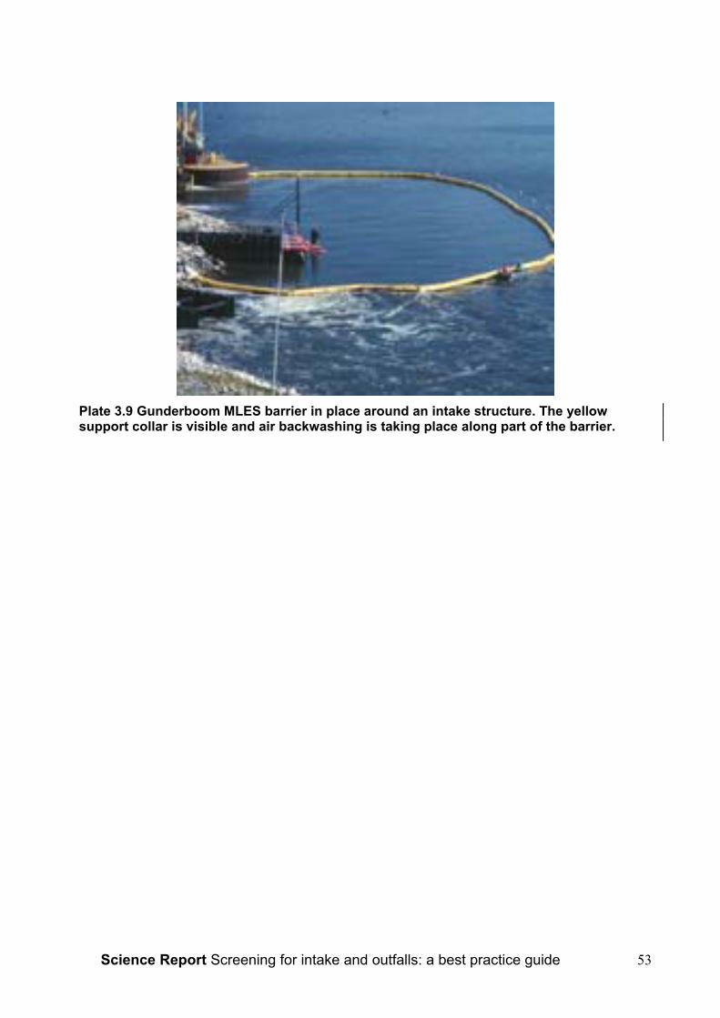
Science Report Screening for intake and outfalls: a best practice guide 53
Plate 3.9 Gunderboom MLES barrier in place around an intake structure. The yellowsupport collar is visible and air backwashing is taking place along part of the barrier.
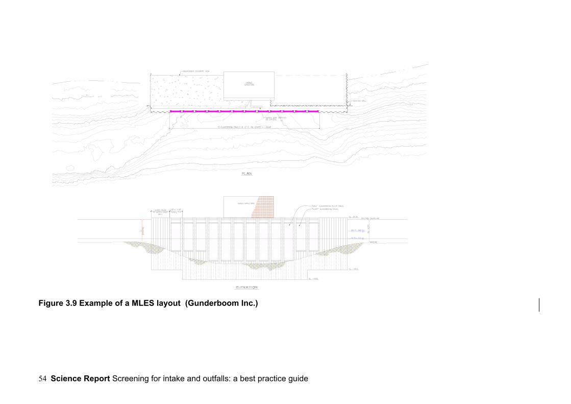
Science Report Screening for intake and outfalls: a best practice guide54
Figure 3.9 Example of a MLES layout (Gunderboom Inc.)

Science Report Screening for intake and outfalls: a best practice guide 55
3.2.4.2 Self-Cleaning with AirBurst™ SystemSimilar to the PWWC screens, the MLES barrier uses an automatic AirBurst™ cleaningsystem. This is intended to remove sediment and organisms that are drawn onto thefabric when high-pressure air (8 bar) is released at the base of the curtain. Bursts ofcompressed air shake the fabric panel.Presumably some tangential flow would be required to carry away debris but themanufacturers do not mention this.
3.2.4.3 Fish Exclusion PerformanceAs the pore size of the fabric is small, the MLES will potentially prevent the passage of allfish down to egg and larval size. Its effectiveness in practice will depend on the integrityof the curtain (freedom from tears, split seams, etc.), achievement of a good seal on theriverbed and banks or intake walls and the ability to resist overtopping by wave action.Raffenberg et al.3 estimated an 80% reduction in larval fish entrainment at the Lovettgenerating station (USA) and while this might be bettered in some environments, it isunlikely that breaches by one of the above mechanisms can be entirely avoided.A further concern is the development of a biofouling community. Despite manufacturer’sclaims that the MLES fabric is biofouling resistant, Henderson4 monitored biofoulingdevelopment over a 30 day period and showed that a diverse community can rapidlydevelop. His concern was not just over the potential for blinding of the pores withconsequent lack of flow but also over the arrival of a number of known predators of larvalfish, including ostracods, amphipods and crabs. He drew attention to the possibility thatthese organisms might crop some of the fish larvae, reducing the benefit of the MLEStechnology.
3.2.4.4 Design and Best PracticeTypically, the MLES technology is used for industrial and power plant applications wherethe through-fabric flow rates are in the range of 4-10 Ls-1m-2 (although the manufacturerssuggest that through a combination of modification to the fabric and alterations to theperforation parameters, it is possible to reach higher sustainable flow rates). Barriers aredesigned to operate at a maximum of 50 mm head differential.
Using the AirBurst cleaning technology in conjunction with what the manufacturersclaim to be a relatively non-biofouling fabric, the filtration-curtain design flow should bemaintained. At present there is some skepticism in North American power plant circlesabout the generality of this claim and it would be unwise to invest heavily in MLESsystems without undertaking pilot-scale site trials to prove the point. In the event of thecurtain becoming temporarily blinded by debris, the system can be designed with reliefmechanisms such that the operation can return to normal after the adjustment. This isaccomplished by having the flotation sized to overtop at certain head differentials and bysizing the ballast on the bottom of the curtain to lift off the bottom given certainpredetermined loading parameters. Large concrete anchors (e.g. 3m x 2.4m x 1.8m) aregenerally required.At Chalk Point generating station, Bailey5 reported the need to remove the barrierperiodically for cleaning and repairs and allowed for 25% replacement of MLES fabricpanels per year. This would need to be done at a time of the year when entrainment riskwas low.

Science Report Screening for intake and outfalls: a best practice guide56
3.2.4.5 ApplicationsThe uses of this technology are less obvious in a UK context than in North America,given the generally smaller sizes of water bodies, other than e.g. at estuarine and marinepower plant sites. Biofouling, in any case, would almost certainly preclude the use of thisapproach in saline waters. At present, it cannot be recommended as an ‘off-the-shelf’solution for UK waters. Nevertheless, it may be amenable for use at lake and reservoirofftakes, and perhaps in slow-moving lowland rivers and canals where space allowedwithout jeopardising navigation. Suitable trialling of the system would first be required.
3.2.4.6 Fish Species/Life StagesSuitable for exclusion of all fish, down to egg and larval size.
3.2.4.7 Ease of RetrofittingThe MLES is intended as a retrofit ‘fix’ for existing abstraction plants and, because ofits simplicity, is likely to be an easy retrofit, provided that space and environmentalconditions (wave climate, boat traffic etc.) are suited.
3.3 Other Positive exclusion Fish ScreensA number of other positive exclusion fish screening methods are used or being trialledoverseas, especially in North America, none of which have so far been introduced intothe UK. In some cases this may simply be a matter of the larger scale of North Americanfacilities and waterways but it is likely that we can learn from these techniques and adaptthem for UK use. It would be premature to present them as “best practice” at this stage.Some of the material presented here has not been formally reported in publications. Anumber of the newer ideas were presented at a recent meeting on intake screeningtechnologies organised by the Electric Power Research Institute (EPRI) at the AldenLaboratories in Massachusetts, USA (30 September 2004). Copies of the presentationsare due to be released on the Internet by EPRI (epri.com).
3.3.1 Barrier NetsFish barrier nets have been used at a number of large US power stations to reduce fishimpingement on cooling water screens. These are large nets that are arranged in an arcin front of the intake and can be several kilometers in length. They are therefore mainlysuited to large water bodies. The size of the mesh needed is a function of the speciespresent, typically varying from 4 mm to 32 mm. There is a risk of gilling fish if the meshesare too large. Diamond meshes are preferable to square meshes, as they do not deformso easily. Design approach velocities are kept to ≤7.5cms-1.The nets are supported on piles spaced 3-12m apart and may be deployed from shore-mounted drum winches, allowing retrieval for maintenance and cleaning. They may bearranged in two tiers, so that a clean net can be put in place before the soiled net isremoved. Maintenance requirements depend on debris and biofouling levels, but wouldtypically be every few weeks. Excessive fouling can cause the nets to lift from thebottom.Barrier nets are most suitable for environments with low biofouling and debris levels, andwhere the fish risk is seasonal, so that they do not need to be in place all year round (ase.g. for many smolt screen installations in the UK).
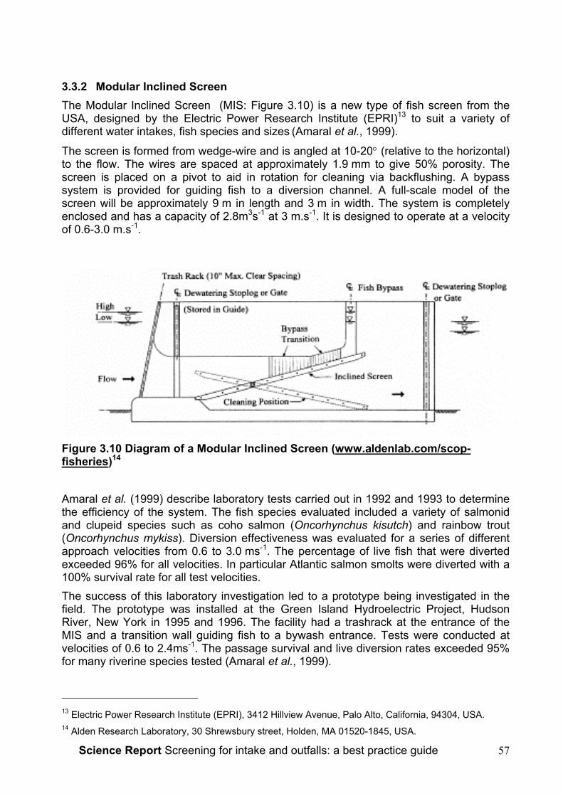
Science Report Screening for intake and outfalls: a best practice guide 57
3.3.2 Modular Inclined ScreenThe Modular Inclined Screen (MIS: Figure 3.10) is a new type of fish screen from theUSA, designed by the Electric Power Research Institute (EPRI)13 to suit a variety ofdifferent water intakes, fish species and sizes (Amaral et al., 1999).
The screen is formed from wedge-wire and is angled at 10-20° (relative to the horizontal)to the flow. The wires are spaced at approximately 1.9 mm to give 50% porosity. Thescreen is placed on a pivot to aid in rotation for cleaning via backflushing. A bypasssystem is provided for guiding fish to a diversion channel. A full-scale model of thescreen will be approximately 9 m in length and 3 m in width. The system is completelyenclosed and has a capacity of 2.8m3s-1 at 3 m.s-1. It is designed to operate at a velocityof 0.6-3.0 m.s-1.
Figure 3.10 Diagram of a Modular Inclined Screen (www.aldenlab.com/scop-fisheries)14
Amaral et al. (1999) describe laboratory tests carried out in 1992 and 1993 to determinethe efficiency of the system. The fish species evaluated included a variety of salmonidand clupeid species such as coho salmon (Oncorhynchus kisutch) and rainbow trout(Oncorhynchus mykiss). Diversion effectiveness was evaluated for a series of differentapproach velocities from 0.6 to 3.0 ms-1. The percentage of live fish that were divertedexceeded 96% for all velocities. In particular Atlantic salmon smolts were diverted with a100% survival rate for all test velocities.The success of this laboratory investigation led to a prototype being investigated in thefield. The prototype was installed at the Green Island Hydroelectric Project, HudsonRiver, New York in 1995 and 1996. The facility had a trashrack at the entrance of theMIS and a transition wall guiding fish to a bywash entrance. Tests were conducted atvelocities of 0.6 to 2.4ms-1. The passage survival and live diversion rates exceeded 95%for many riverine species tested (Amaral et al., 1999).
13 Electric Power Research Institute (EPRI), 3412 Hillview Avenue, Palo Alto, California, 94304, USA.14 Alden Research Laboratory, 30 Shrewsbury street, Holden, MA 01520-1845, USA.

Science Report Screening for intake and outfalls: a best practice guide58
In principle this would appear to offer a good solution to protecting juvenile fish such aselvers, lampreys and coarse fish at run-of-river hydroelectric projects but large size andhigh costs relative to flow may in practice limit application to higher head sites, whereCoanda screens already have a track-record.
3.3.3 Self-Cleaning Belt ScreensThis concept was presented at the EPRI meeting of 30/09/04 (Mr. Greg Gerow, FPI,personal communication) as a possible method for power plant cooling water screening.The screening system is similar to a band-screen, comprising a continuously movingconveyor belt of fine mesh (2.4mm) but whereas band screens are normally used withinthe plant, some way downstream of the intake, the is screen is fitted at the primary intakepoint on the river or water body. The screen described was operated inclined at an angleof 54o to the horizontal, below the water at the lower end to screen the water intake; theupper part emerged through the water surface to deposit accumulated debris. Thelongest practical screen length is 15m. The screens can be deployed side-by-side toincrease the filtration area.The mesh is a ‘fish-friendly’, smooth stainless woven material. The screens have beenused widely for screening irrigation intakes, with >700 systems installed. There has beenno reported evidence of fish loss at existing installations although formal testing does notappear to have been carried out. A large surface area and low approach velocity(0.15ms-1) are used with the aim of not impinging fish at all.
Plate 3.10 Example of a self-cleaning belt screen installation. The screens aresealed at the sides to prevent fish or debris entrainment; screened weed and otherdebris are dumped on the ground below the top of the screen (courtesy of FPIWater Screens, USA: www.fpi-co.com)This type of screen appears suitable for a wide range of applications where self-cleaning,fine-meshed screens are required and may provide a more cost-effective alternative toPWWC screens in some cases. Being of stainless steel construction, it will not be proofagainst biofouling and therefore it is likely to be suitable only for freshwater applications.At exposed sites, trash racks may be required upstream to protect the fine meshes from
Science Report Screening for intake and outfalls: a best practice guide 59
flood damage. The design is well suited to intakes that lie flush with the bank and it mayoffer a retrofit option for many bankside intakes that are presently protected trashracksalone.
3.3.4 Labyrinth ScreensLabyrinth screens are a variation on the flat panel screen or bar rack described in section3.1. In this case, vertical bar racks are arranged in chevron-formations (when seen inplan view: Figure 3.11), rather like an array of fyke-nets. The fish are guided intobywashes located at the downstream angle of the ‘V’. The bar spacing can be specifiedas usual, according to the sizes of fish to be excluded.Meritec15, source of the following information, recently reviewed the labyrinth screen forpossible application at a large water intake on the River Waitiki, New Zealand. The riverhas the potential for six 90 MW capacity hydropower stations. A form of screen wasneeded in order to exclude ≥90% of the river’s twenty indigenous and four introducedspecies from flows of >300m3s-1, making this one of the largest fish screening projects inthe world. The screen must exclude both adults and juveniles (25-1000 mm in length) ofa range of species including salmonids and eels and be in place all year round. In orderto avoid any impingement the maximum contact time has been specified at 60 seconds.The proposed screen gap size is 5 mm with bars orientated vertically.
15 Meritec Limited, 47 George Street, Newmarket, Po Box 4241, Auckland, New Zealand.

Science Report Screening for intake and outfalls: a best practice guide60
Figure 3.11 River Waitiki arrangement plan for the Labyrinth screen(www.ecan.govt.nz/consents/project-aqua)
The system is based on the 97-98% efficiency seen at the White River labyrinth screenin the USA. This screen is operated at a similar flow and angle as proposed for thisinstallation and successfully excludes chinook salmon fry (Oncorhynchus tshawytscha)although using a slightly smaller screen gap of 3.1mm.The proposed system would consist of wedge-wire screen panels, a collection systemand a return system to transport collected fish back to the river. To obtain a low approachvelocity the screen would be angled at 8½° to the flow. The labyrinth arrangementconfines the screen to a relatively short length of canal making both operation and fishcollection easier. A total of 7 labyrinth bays would require 40 m of canal whereas singleline vertical screens would require 600 m. A full-height bywash opening and width of 600-900 mm allows fish collection over the full flow depth. Primary screens would consist of
Science Report Screening for intake and outfalls: a best practice guide 61
bars running perpendicular to the sweeping velocity in order to minimise head loss. Animpermeable ramp on the bed angled at 45° ensures accelerating flow into the bywash.The labyrinth screen concept could be of benefit in the UK at large intakes or wherespace is at a premium and a compact screening arrangement is required. Low-headhydro would be an obvious application.
3.4 Behavioural Barrier and Guidance Methods
3.4.1 Behavioural Deterrents BackgroundDeterrent methods are normally used where positive exclusion fish screening isimpracticable, owing to the risk of fouling, either by attached biofouling or by waterborneorganisms and debris. Fish deterrent systems are commonly known as ‘behaviouralbarriers’ or ‘behavioural screens’ and are a substitute for, or supplement to, moreconventional positive exclusion fish screens. Whereas some positive exclusion screens,when operated and maintained correctly can achieve 100% fish exclusion, behaviouralscreens cannot.Fish have a number of well developed senses, and are able to detect and react to light,sound and vibration, temperature, taste and odour, pressure change, touch, hydraulicshear, acceleration, electrical and possibly magnetic fields. The relative sensitivity andcapacity to react to any of these stimuli varies with individual species and life stages,each being well adapted to cope with the conditions it is likely to encounter in itsparticular lifestyle. Environmental variables, such as flow, depth, turbidity, watertemperature and others may also affect the success of behavioural methods.Fish deterrent methods depend on the use of one or more of these stimuli to causerepulsion of fish from the immediate area of the water intake, and in some cases to guidethem past the intake into a bywash or to a point downstream. To be effective, thestimulus must be strong enough to repel fish at a range where they are not at risk ofbeing involuntarily drawn in by the strength of the water current. Equally, it must be weakenough to avoid the risk of injuring the fish or of clearing fish from too large an area,which might cause habitat loss and impact upon commercial fishing or block naturalpatterns of fish migration in rivers.
3.4.2 Louvre Screens
3.4.2.1 Description of ScreenLouvre screens have been used since the 1950s and can be an effective option for thediversion of salmonids and other species. They are in fact a semi-physical barrier whichcan provide high fish deflection efficiencies (>90%) under optimal conditions (Aitken etal, 1966, Solomon, 1992). In general the efficiency of louvre devices varies between 80-100%. In particular high efficiencies have been found for adult and juvenile salmonids aswell as American shad (Alosa sapidissima), the efficiency is however, lower for alevinsand individuals under 5 cm in length. Bottom dwelling fish are not as efficiently deflected,especially where only partial depth louvres are used (Therrien, 2000, Buerkett, 1994,Kynard and Buerkett, 1997).The louvre screen is based on the reaction of fish to current vortices created by theaction of water flow on the louvre slats (Figure 3.12). Approaching fish sense a shearingflow (i.e. different velocities across different points along its body) and as a result avoid
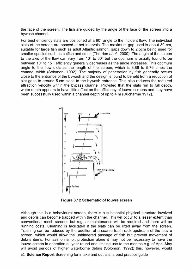
Science Report Screening for intake and outfalls: a best practice guide62
the face of the screen. The fish are guided by the angle of the face of the screen into abywash channel.
For best efficiency slats are positioned at a 90° angle to the incident flow. The individualslats of the screen are spaced at set intervals. The maximum gap used is about 30 cm,suitable for large fish such as adult Atlantic salmon, gaps down to 2.5cm being used forsmaller species such as catfish and smelt (Therrien et al., 2000). The angle of the screento the axis of the flow can vary from 10° to 30° but the optimum is usually found to bebetween 10° to 15°; efficiency generally decreases as the angle increases. This optimumangle to the flow dictates the length of the screen, which is 3.86 to 5.76 times thechannel width (Solomon, 1992). The majority of penetration by fish generally occursclose to the entrance of the bywash and the design is found to benefit from a reduction ofslat gaps to around 5 cm close to the bywash entrance. This also reduces the requiredattraction velocity within the bypass channel. Provided that the slats run to full depth,water depth appears to have little effect on the efficiency of louvre screens and they havebeen successfully used within a channel depth of up to 4 m (Ducharme 1972).
Figure 3.12 Schematic of louvre screen
Although this is a behavioural screen, there is a substantial physical structure involvedand debris can become trapped within the channel. This will occur to a lesser extent thanconventional mesh screens but regular maintenance will be required and there will berunning costs. Cleaning is facilitated if the slats can be lifted away from the screen.Trashing can be reduced by the addition of a coarse trash rack upstream of the louvrescreen, which would allow the unhindered passage of fish but prevent movement ofdebris items. For salmon smolt protection alone it may not be necessary to have thelouvre screen in operation all year round and limiting use to the months e.g. of April-Maywill avoid periods of higher waterborne debris (Solomon, 1992); this, however, would
Science Report Screening for intake and outfalls: a best practice guide 63
require the negotiation of an exemption under SFFA s.14 unless a local byelaw alreadyallowed this. In some rivers, screening may also be required during the autumn andwinter months to protect pre-smolt migrations.The range of suitable current velocities in the channel has been described in a number ofpapers and louvre screens have been shown to work from 0.3 – 1.2 ms-1 with no loss inefficiency, but they become ineffective as the approach velocity falls below this as shearflows are not generated. The water velocity perpendicular to the face of the louvre array(the ‘escape velocity’) must be less than the fishes’ swimming ability. The velocity in thebywash entrance, however, must be greater than that of the channel in order to providesufficient attraction. Of velocities tested within the range of 110-300% of the screenapproach velocity, a figure of 140% is considered to be the ideal (Solomon, 1992). As thelouvre screen itself restricts the water velocity in the main channel a bywash velocity of1.4 times the main channel is generally easily achieved. At sites where headloss may bea problem the louvres can be fitted with deflectors or current rectifiers along the louvresline at regular intervals to improve hydraulic efficiency (Therrien, 2000).
3.4.2.2 Floating or partial-depth louvresFloating louvres can be used when screening of just the surface layers is required. Thismay be the case when screening for fish that only travel in the upper layers of the watercolumn such as salmon smolts, which migrate predominantly in the top 2 m of water.Shad, on the other hand, tend to migrate in the bottom layers. It is believed that withfloating devices the current velocity should not exceed 1 ms-1 and that the optimumcurrent for which designs are based on is 0.6 ms-1 (Therrien, 2000). Ruggles (1990)described a floating louvre screen array fitted at a hydroelectric scheme at Holyoke onthe Connecticut River. Based on observations that salmon smolts tend to migrate only inthe top metre or two of water, the screen extended over the upper 2.4 m of the 5.5 mwater column. The louvre slats were constructed of polypropylene, suspended at76.2 mm (3”) centres along a 176 m array. This created a screen angle of 15o across a44m-wide channel, with a total flow of about 150 m3s-1. Tests with radio-tagged smoltsindicated that 90% were successfully guided into the 4 m wide bypass channel.Experience of one of the authors (AWHT) at a hydro station in southern Swedensuggests that the success of partial-depth louvres may be dependent on the flowcharacteristics of the channel. A smolt trap located at the Upper Hemsjo hydro station onthe Morrumso River was intended to take advantage of the deflection of smoltsswimming near the surface into the trap by an angled ice deflector. This was formed by ametal curtain suspended in the headrace from a floating boom, which was angled acrossthe channel to deflect ice into a bywash chute. The curtain hung a metre or so below thewater surface. When very few smolts were found to enter the trap, even though theywere observed in the headrace, behavioural observations were made of smolts fitted withfloat tags (small polystyrene cubes attached to the dorsal fin by a monofilament line)released upstream. It was found that smolts followed the line of the ice boom along mostof its length but at a point where it lay nearer to the turbine intake, the flow began todescend towards the submerged intake openings. The smolts were clearly able to detectthis descending flow and immediately sounded down below the curtain and passedthrough the turbine. This observation suggests that partial-depth barrier of any kind areonly likely to be effective when flow is uniformly horizontal in direction.
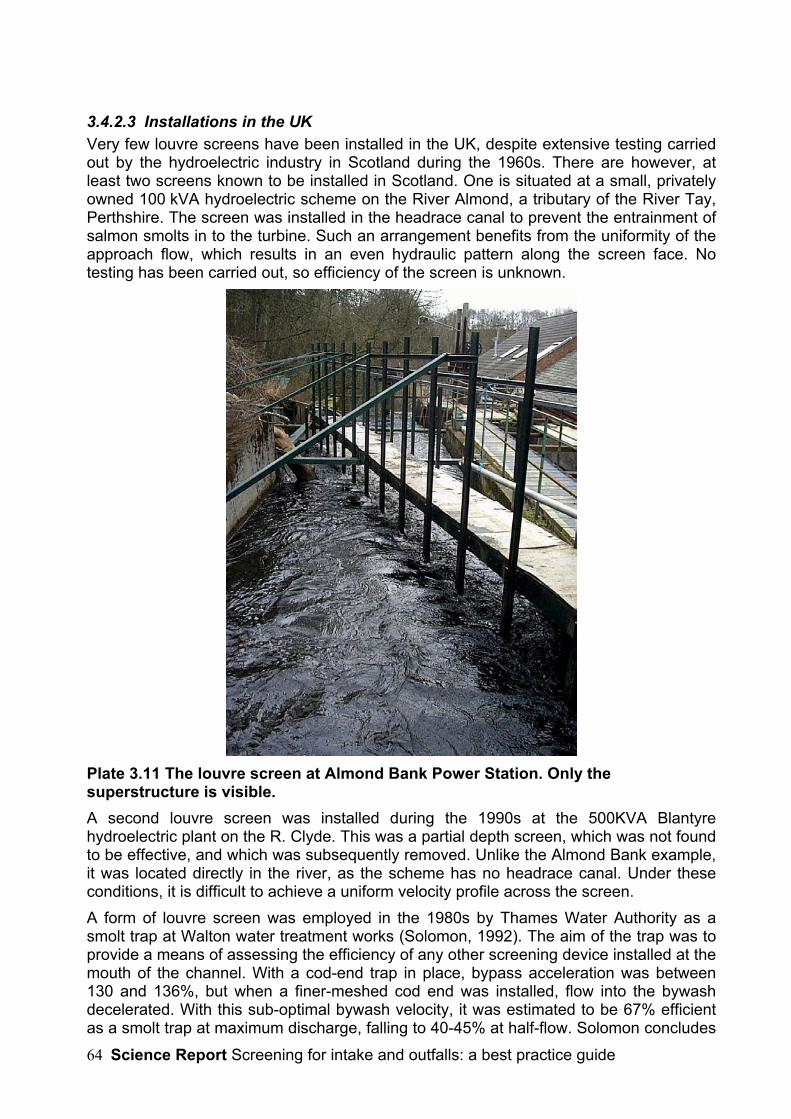
Science Report Screening for intake and outfalls: a best practice guide64
3.4.2.3 Installations in the UKVery few louvre screens have been installed in the UK, despite extensive testing carriedout by the hydroelectric industry in Scotland during the 1960s. There are however, atleast two screens known to be installed in Scotland. One is situated at a small, privatelyowned 100 kVA hydroelectric scheme on the River Almond, a tributary of the River Tay,Perthshire. The screen was installed in the headrace canal to prevent the entrainment ofsalmon smolts in to the turbine. Such an arrangement benefits from the uniformity of theapproach flow, which results in an even hydraulic pattern along the screen face. Notesting has been carried out, so efficiency of the screen is unknown.
Plate 3.11 The louvre screen at Almond Bank Power Station. Only thesuperstructure is visible.A second louvre screen was installed during the 1990s at the 500KVA Blantyrehydroelectric plant on the R. Clyde. This was a partial depth screen, which was not foundto be effective, and which was subsequently removed. Unlike the Almond Bank example,it was located directly in the river, as the scheme has no headrace canal. Under theseconditions, it is difficult to achieve a uniform velocity profile across the screen.A form of louvre screen was employed in the 1980s by Thames Water Authority as asmolt trap at Walton water treatment works (Solomon, 1992). The aim of the trap was toprovide a means of assessing the efficiency of any other screening device installed at themouth of the channel. With a cod-end trap in place, bypass acceleration was between130 and 136%, but when a finer-meshed cod end was installed, flow into the bywashdecelerated. With this sub-optimal bywash velocity, it was estimated to be 67% efficientas a smolt trap at maximum discharge, falling to 40-45% at half-flow. Solomon concludes
Science Report Screening for intake and outfalls: a best practice guide 65
that very much higher efficiencies should have been attainable with increased bywashacceleration.
3.4.2.4 Design and Operational Best PracticeFor best performance, louvre screens should be designed with the followingcharacteristics:
• The screen array should be aligned at an angle of 10-15o to the channel axis;the slats should be orientated at 90o to the flow.
• The required slat spacing depends on the size of fish to be diverted, rangingfrom 30 cm for adult salmon or similarly sized fish, down to 5 cm for juveniles andsmaller species. Where smaller slat spacings are needed, they can be arrangedso that spacings gradually decrease to the required space along the length of thearray, towards the bywash, taking advantage of the reluctance of fish to cross theshear. Flow straighteners should be used to achieve optimal performance.
• Approach velocities should be between 0.3-1.0 ms-1 at all times.
• Provision should be made for cleaning the louvres, e.g. by having upstreamtrash racks to catch most of the debris or by having removable slats. Safe accessshould be provided for this purpose, e.g. via an overhead walkway with safetyhandrails.
• The screen should run to the full river depth, unless it can be demonstratedthat adequate efficiency can be maintained with a partial depth screen (e.g. forsurface-swimming fish such as smolts). However, it should not be assumed thatall smolts swim at the surface, as smolts tend to sound to the bottom on sensingdanger.
• Louvre screens operate best when sited within a headrace canal, or othersituations where uniform approach velocities can be achieved. Hydraulicmodelling may be beneficial to assess the uniformity of approach flow.
• The bywash entrance design velocity should be around 140% of the screenapproach velocity.
• For a more compact arrangement, louvre screens can be arranged in a V-shape (in plan), with the bywash located in the centre (see also Labyrinth screenarrangement (section 3.3).
Low or high velocities will impair screening efficiency, as will any accumulation of debrison the slats. It is important to recognise that they will not prevent fish entry when thewater is very slow or static. This means that, for example, on a hydroelectric plant, fishmay get past the screen when the turbines are shut down and subsequently be at risk ofinjury within the turbine(s).
3.4.2.5 ApplicationsLouvre screens are best suited to canalized waterways where a uniform approach flowcan be achieved. They are advantageous over physical screens where large flows mustbe screened with minimal head loss (e.g. low-head hydroelectric plant). They may beunsuitable for locations subject to inundations of weed, e.g. on chalk streams whereweed cutting is carried out.
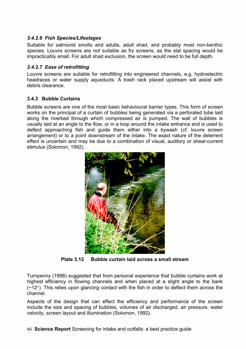
Science Report Screening for intake and outfalls: a best practice guide66
3.4.2.6 Fish Species/LifestagesSuitable for salmonid smolts and adults, adult shad, and probably most non-benthicspecies. Louvre screens are not suitable as fry screens, as the slat spacing would beimpracticably small. For adult shad exclusion, the screen would need to be full depth.
3.4.2.7 Ease of retrofittingLouvre screens are suitable for retrofitting into engineered channels, e.g. hydroelectricheadraces or water supply aqueducts. A trash rack placed upstream will assist withdebris clearance.
3.4.3 Bubble CurtainsBubble screens are one of the most basic behavioural barrier types. This form of screenworks on the principal of a curtain of bubbles being generated via a perforated tube laidalong the riverbed through which compressed air is pumped. The wall of bubbles isusually laid at an angle to the flow, or in a loop around the intake entrance and is used todeflect approaching fish and guide them either into a bywash (cf. louvre screenarrangement) or to a point downstream of the intake. The exact nature of the deterrenteffect is uncertain and may be due to a combination of visual, auditory or shear-currentstimulus (Solomon, 1992).
Plate 3.12 Bubble curtain laid across a small stream
Turnpenny (1998) suggested that from personal experience that bubble curtains work athighest efficiency in flowing channels and when placed at a slight angle to the bank(~12°). This relies upon glancing contact with the fish in order to deflect them across thechannel.Aspects of the design that can effect the efficiency and performance of the screeninclude the size and spacing of bubbles, volumes of air discharged, air pressure, watervelocity, screen layout and illumination (Solomon, 1992).
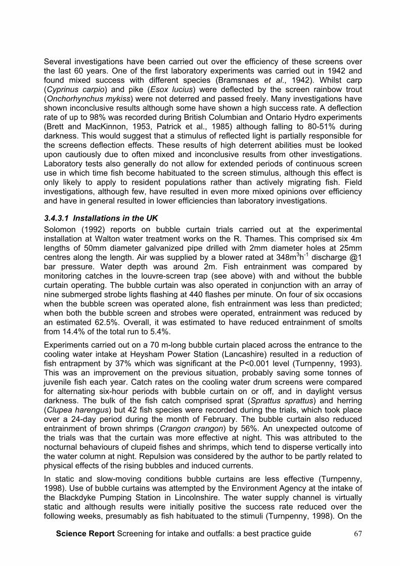
Science Report Screening for intake and outfalls: a best practice guide 67
Several investigations have been carried out over the efficiency of these screens overthe last 60 years. One of the first laboratory experiments was carried out in 1942 andfound mixed success with different species (Bramsnaes et al., 1942). Whilst carp(Cyprinus carpio) and pike (Esox lucius) were deflected by the screen rainbow trout(Onchorhynchus mykiss) were not deterred and passed freely. Many investigations haveshown inconclusive results although some have shown a high success rate. A deflectionrate of up to 98% was recorded during British Columbian and Ontario Hydro experiments(Brett and MacKinnon, 1953, Patrick et al., 1985) although falling to 80-51% duringdarkness. This would suggest that a stimulus of reflected light is partially responsible forthe screens deflection effects. These results of high deterrent abilities must be lookedupon cautiously due to often mixed and inconclusive results from other investigations.Laboratory tests also generally do not allow for extended periods of continuous screenuse in which time fish become habituated to the screen stimulus, although this effect isonly likely to apply to resident populations rather than actively migrating fish. Fieldinvestigations, although few, have resulted in even more mixed opinions over efficiencyand have in general resulted in lower efficiencies than laboratory investigations.
3.4.3.1 Installations in the UKSolomon (1992) reports on bubble curtain trials carried out at the experimentalinstallation at Walton water treatment works on the R. Thames. This comprised six 4mlengths of 50mm diameter galvanized pipe drilled with 2mm diameter holes at 25mmcentres along the length. Air was supplied by a blower rated at 348m3h-1 discharge @1bar pressure. Water depth was around 2m. Fish entrainment was compared bymonitoring catches in the louvre-screen trap (see above) with and without the bubblecurtain operating. The bubble curtain was also operated in conjunction with an array ofnine submerged strobe lights flashing at 440 flashes per minute. On four of six occasionswhen the bubble screen was operated alone, fish entrainment was less than predicted;when both the bubble screen and strobes were operated, entrainment was reduced byan estimated 62.5%. Overall, it was estimated to have reduced entrainment of smoltsfrom 14.4% of the total run to 5.4%.Experiments carried out on a 70 m-long bubble curtain placed across the entrance to thecooling water intake at Heysham Power Station (Lancashire) resulted in a reduction offish entrapment by 37% which was significant at the P<0.001 level (Turnpenny, 1993).This was an improvement on the previous situation, probably saving some tonnes ofjuvenile fish each year. Catch rates on the cooling water drum screens were comparedfor alternating six-hour periods with bubble curtain on or off, and in daylight versusdarkness. The bulk of the fish catch comprised sprat (Sprattus sprattus) and herring(Clupea harengus) but 42 fish species were recorded during the trials, which took placeover a 24-day period during the month of February. The bubble curtain also reducedentrainment of brown shrimps (Crangon crangon) by 56%. An unexpected outcome ofthe trials was that the curtain was more effective at night. This was attributed to thenocturnal behaviours of clupeid fishes and shrimps, which tend to disperse vertically intothe water column at night. Repulsion was considered by the author to be partly related tophysical effects of the rising bubbles and induced currents.In static and slow-moving conditions bubble curtains are less effective (Turnpenny,1998). Use of bubble curtains was attempted by the Environment Agency at the intake ofthe Blackdyke Pumping Station in Lincolnshire. The water supply channel is virtuallystatic and although results were initially positive the success rate reduced over thefollowing weeks, presumably as fish habituated to the stimuli (Turnpenny, 1998). On the

Science Report Screening for intake and outfalls: a best practice guide68
other hand fast, turbulent or deep waters can lead to break-up of the bubble sheet withloss of efficiency. This is important as performance may deteriorate at the most criticaltime for fish that migrate on floodwaters. The maximum reliable depth for a bubblecurtain is about 3 m; above this, the bubbles tend to form cords, which split apart, leavinggaps. This could potentially be overcome by placing bubble pipes at height intervals of≤3 m in the water column but this is not straightforward and puts the pipes at risk ofdamage by flood debris.To achieve the most effective performance from a bubble curtain a strong flow of airmust be used. The most economical way of generating the air supply depends on theflow rate, depth and application of the specific project. When used in less than 2m ofwater a simple, low pressure rotary blower gives economical and reliable mechanicalperformance, whereas for greater depths a multi-stage blower or air compressor may beneeded to overcome the greater hydrostatic pressure (Turnpenny, 1998).Before installing a bubble curtain certain behaviours of bubbles must be taken intoaccount. Bubbles larger than 2mm in size will rise through the water at a rate ofapproximately 0.25ms-1; smaller bubble sizes are not recommended in moving water, asthey rise too slowly. Before installation, the surfacing line of the bubbles should becalculated from the velocity of the water in order to determine the correct positioning ofthe barrier on the bed. Where a bywash is used, the width of the mouth must be able toaccommodate any variation in surfacing position, otherwise fish may not find theentrance. It may be necessary to have more than one bubble pipe in order toaccommodate any changes in flow conditions. The bubble curtain itself will also create acertain degree of turbulence and may therefore require some fine-tuning of airflow toachieve a uniform curtain of bubbles (Turnpenny, 1998).A bubble curtain was recently installed at the entrance to the cooling water intake atFawley Power Station (Hampshire). An acoustic fish deterrent (AFD) system was alsoinstalled. The application is unusual, since the curtain is not intended to deflect fishdirectly (although it may have some benefit in this respect) but to help prevent a build upof silt in the channel, which might increase the intake velocity and impair the propagationof sound from the AFD.
3.4.3.2 Bubble screens in combination with other behavioural stimuliCombinations of bubble curtains with other types of behavioural screens generallyachieve greater efficiencies than when used alone. The best combinations involveadding acoustic and or artificial light stimuli.A combination of bubble curtains and strobe lights used at Walton-on-Thames has beendescribed above. Another was tested by Sager et al. (1987). Very low efficiencies werefound for bubble curtains alone with very little effect being seen in all species. Oncombining bubble screens with strobe lights at a flash rate of 300 min-1, up to 100%efficiency was seen in spot (Leiostomus xanthurus), 68% for menhaden (Brevoortiatyrannus) and 36% for white perch (Morone americana).The second option involves the combination of a sound generator with a bubble sheetcreating a ‘wall of sound’ that can be used to guide fish into a bywash. The system isknown as a ‘Bioacoustic Fish Fence’ (BAFF) and is designed by Fish GuidanceSystems (FGS). Further details of light and acoustic barriers are given below.
3.4.3.3 Design Best PracticeKey points in good bubble curtain design and operation are:

Science Report Screening for intake and outfalls: a best practice guide 69
• ensure that a uniform bubble sheet, free of large gaps, is maintained under all flowconditions where fish exclusion is required; hole spacings in bubble curtain designare considered roughly analogous to bar separations in bar screens, so do notexpect 15 cm hole spacings to exclude smolts! Small holes of 0.5-2 mm borespaced at 1-3 cm are usually effective.
• allow for plenty of air flow: at least 1 ls-1 per metre of barrier length and up to 4 ls-1;
• estimate the velocity profile along the proposed screen line for the range ofexpected conditions and calculate the surfacing lines under various scenarios,making sure that the curtain leads into the bywash entrance (if applicable);
• select a position where the depth along the line is as uniform as possible to avoidloss of air flow in deeper areas; avoid areas where the bed is unstable;
• for best results, angle the curtain near-parallel to the flow and preferably at anangle of more than 15o to the channel flow;
• check the bubble pipe regularly and keep it clear of bed materials and biofouling;blockage is more likely to occur if the curtain is not operated continuously; checkfor uniformity of the surface air plume.
• warning systems (e.g. via telemetry links or visual inspection) should be providedto inform plant operators of air supply failure.
• The equipment requires regular maintenance and service intervals should bedisplayed and logged in the plant control room.
• Back-up power or interlocks with pump controls may need to be provided toensure that pumping does not occur when the system has lost power.
3.4.3.4 ApplicationsBubble curtains may be used as a low-cost behavioural barrier in flowing water situationswhere high performance is not demanded. Fast-flowing or deep water may lead to anunacceptable breakup of the curtain’s integrity, reducing effectiveness.
3.4.3.5 Fish Species and LifestagesMany fish species, including UK salmonids, clupeids and cyprinids can be deflected by abubble barrier but habituation is rapid. Consequently they are best suited to deflection ofmigrating fish in rivers, or of fish moving with the tide in tidal systems. In these situationscontact time is likely to be short. Bubble curtains alone are probably ineffective for eelsand lampreys, but the addition of artificial lights or strobe lights enhances their efficiencyfor eel deflection (see below). There is a risk, however, that illumination may attract somespecies, for example 3-spined stickleback (Gasterosteus aculeatus) (Hadderingh, 1982).
3.4.3.6 Ease of retrofittingBubble curtains can easily be retrofitted to almost any existing application.
3.4.4 Electric BarriersElectric intake screens were first developed in the 1950s by MAFF Fisheries Laboratory.After their development several were installed across the UK but most were laterremoved over fears of their safety. The effectiveness of such screens is uncertain andhas historically been thrown into doubt. As well as uncertainty over the efficiency there
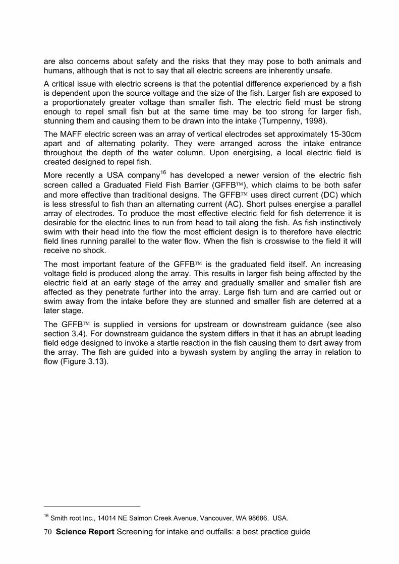
Science Report Screening for intake and outfalls: a best practice guide70
are also concerns about safety and the risks that they may pose to both animals andhumans, although that is not to say that all electric screens are inherently unsafe.A critical issue with electric screens is that the potential difference experienced by a fishis dependent upon the source voltage and the size of the fish. Larger fish are exposed toa proportionately greater voltage than smaller fish. The electric field must be strongenough to repel small fish but at the same time may be too strong for larger fish,stunning them and causing them to be drawn into the intake (Turnpenny, 1998).The MAFF electric screen was an array of vertical electrodes set approximately 15-30cmapart and of alternating polarity. They were arranged across the intake entrancethroughout the depth of the water column. Upon energising, a local electric field iscreated designed to repel fish.More recently a USA company16 has developed a newer version of the electric fishscreen called a Graduated Field Fish Barrier (GFFB), which claims to be both saferand more effective than traditional designs. The GFFB uses direct current (DC) whichis less stressful to fish than an alternating current (AC). Short pulses energise a parallelarray of electrodes. To produce the most effective electric field for fish deterrence it isdesirable for the electric lines to run from head to tail along the fish. As fish instinctivelyswim with their head into the flow the most efficient design is to therefore have electricfield lines running parallel to the water flow. When the fish is crosswise to the field it willreceive no shock.
The most important feature of the GFFB is the graduated field itself. An increasingvoltage field is produced along the array. This results in larger fish being affected by theelectric field at an early stage of the array and gradually smaller and smaller fish areaffected as they penetrate further into the array. Large fish turn and are carried out orswim away from the intake before they are stunned and smaller fish are deterred at alater stage.
The GFFB is supplied in versions for upstream or downstream guidance (see alsosection 3.4). For downstream guidance the system differs in that it has an abrupt leadingfield edge designed to invoke a startle reaction in the fish causing them to dart away fromthe array. The fish are guided into a bywash system by angling the array in relation toflow (Figure 3.13).
16 Smith root Inc., 14014 NE Salmon Creek Avenue, Vancouver, WA 98686, USA.
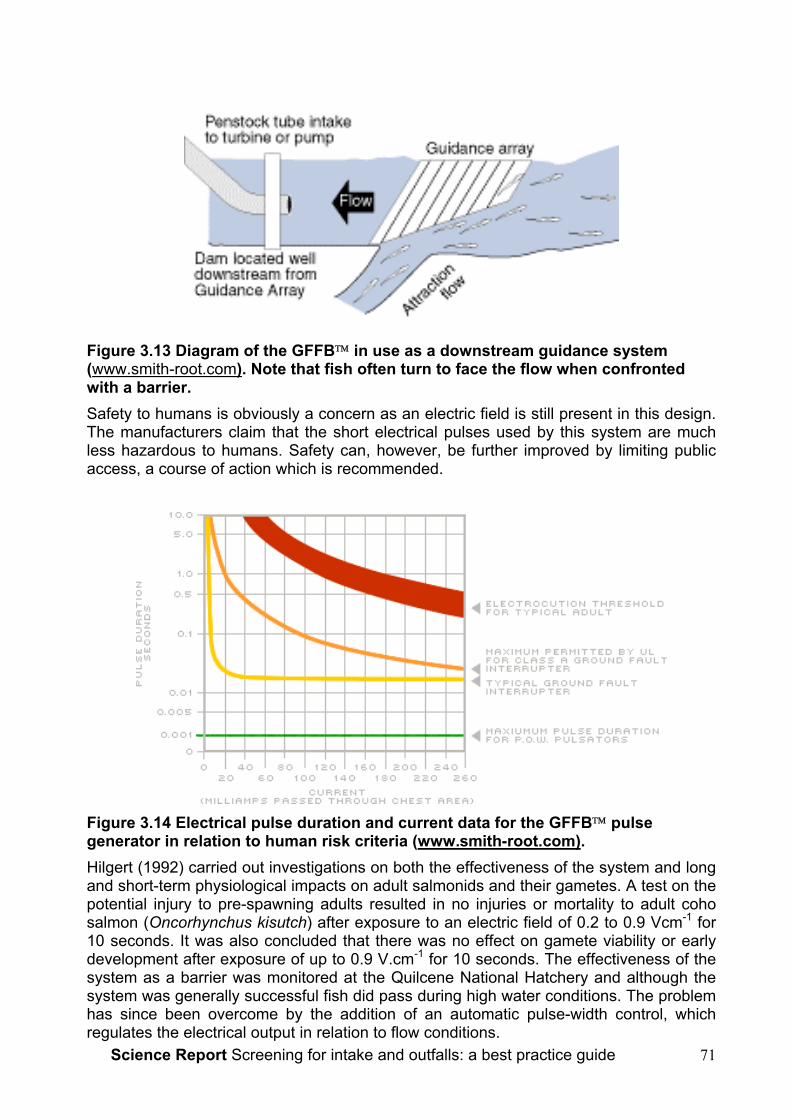
Science Report Screening for intake and outfalls: a best practice guide 71
Figure 3.13 Diagram of the GFFB in use as a downstream guidance system(www.smith-root.com). Note that fish often turn to face the flow when confrontedwith a barrier.Safety to humans is obviously a concern as an electric field is still present in this design.The manufacturers claim that the short electrical pulses used by this system are muchless hazardous to humans. Safety can, however, be further improved by limiting publicaccess, a course of action which is recommended.
Figure 3.14 Electrical pulse duration and current data for the GFFB pulsegenerator in relation to human risk criteria (www.smith-root.com).Hilgert (1992) carried out investigations on both the effectiveness of the system and longand short-term physiological impacts on adult salmonids and their gametes. A test on thepotential injury to pre-spawning adults resulted in no injuries or mortality to adult cohosalmon (Oncorhynchus kisutch) after exposure to an electric field of 0.2 to 0.9 Vcm-1 for10 seconds. It was also concluded that there was no effect on gamete viability or earlydevelopment after exposure of up to 0.9 V.cm-1 for 10 seconds. The effectiveness of thesystem as a barrier was monitored at the Quilcene National Hatchery and although thesystem was generally successful fish did pass during high water conditions. The problemhas since been overcome by the addition of an automatic pulse-width control, whichregulates the electrical output in relation to flow conditions.
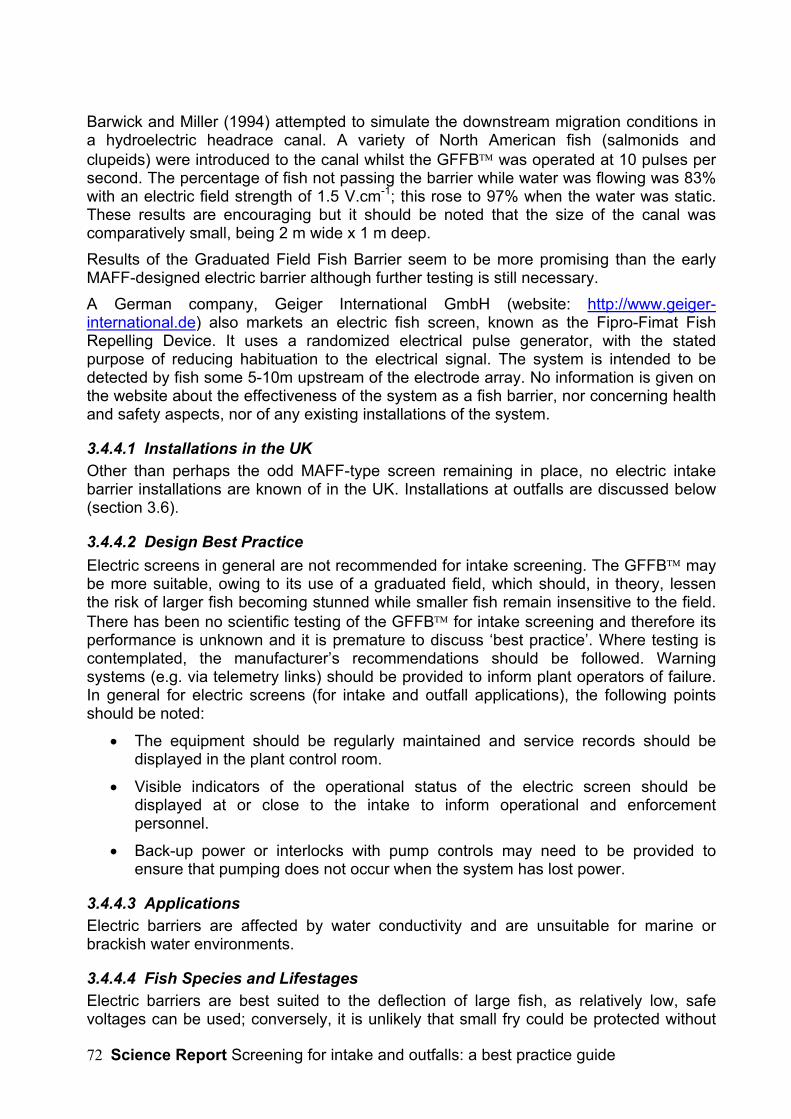
Science Report Screening for intake and outfalls: a best practice guide72
Barwick and Miller (1994) attempted to simulate the downstream migration conditions ina hydroelectric headrace canal. A variety of North American fish (salmonids andclupeids) were introduced to the canal whilst the GFFB was operated at 10 pulses persecond. The percentage of fish not passing the barrier while water was flowing was 83%with an electric field strength of 1.5 V.cm-1; this rose to 97% when the water was static.These results are encouraging but it should be noted that the size of the canal wascomparatively small, being 2 m wide x 1 m deep.Results of the Graduated Field Fish Barrier seem to be more promising than the earlyMAFF-designed electric barrier although further testing is still necessary.A German company, Geiger International GmbH (website: http://www.geiger-international.de) also markets an electric fish screen, known as the Fipro-Fimat FishRepelling Device. It uses a randomized electrical pulse generator, with the statedpurpose of reducing habituation to the electrical signal. The system is intended to bedetected by fish some 5-10m upstream of the electrode array. No information is given onthe website about the effectiveness of the system as a fish barrier, nor concerning healthand safety aspects, nor of any existing installations of the system.
3.4.4.1 Installations in the UKOther than perhaps the odd MAFF-type screen remaining in place, no electric intakebarrier installations are known of in the UK. Installations at outfalls are discussed below(section 3.6).
3.4.4.2 Design Best PracticeElectric screens in general are not recommended for intake screening. The GFFB maybe more suitable, owing to its use of a graduated field, which should, in theory, lessenthe risk of larger fish becoming stunned while smaller fish remain insensitive to the field.There has been no scientific testing of the GFFB for intake screening and therefore itsperformance is unknown and it is premature to discuss ‘best practice’. Where testing iscontemplated, the manufacturer’s recommendations should be followed. Warningsystems (e.g. via telemetry links) should be provided to inform plant operators of failure.In general for electric screens (for intake and outfall applications), the following pointsshould be noted:
• The equipment should be regularly maintained and service records should bedisplayed in the plant control room.
• Visible indicators of the operational status of the electric screen should bedisplayed at or close to the intake to inform operational and enforcementpersonnel.
• Back-up power or interlocks with pump controls may need to be provided toensure that pumping does not occur when the system has lost power.
3.4.4.3 ApplicationsElectric barriers are affected by water conductivity and are unsuitable for marine orbrackish water environments.
3.4.4.4 Fish Species and LifestagesElectric barriers are best suited to the deflection of large fish, as relatively low, safevoltages can be used; conversely, it is unlikely that small fry could be protected without

Science Report Screening for intake and outfalls: a best practice guide 73
using excessively high voltage. The GFFB would appear to lend itself to diversion ofeels and lampreys, being elongate species that swim close to the riverbed. This meritsfurther testing in the UK.
3.4.4.5 Ease of RetrofittingThe traditional MAFF-type electrode array was a very simple retrofit to almost any kind ofintake. The GFFB is less straightforward to retrofit, as the electrodes must be attachedto a flat bed/walls of insulating material. Nevertheless, this is not usually an insuperablecivil engineering task.
3.4.5 Acoustic GuidanceThe hearing range of most fish falls within the audible range to humans, maximumsensitivity lying in the sub-3 kHz band down to infrasound frequencies (Hawkins, 1981;Sand and Karlsen, 1986). Acoustic fish deterrent (AFD) systems mostly exploit hearingsensitivity in the 20 to 500 Hz range, although infrasound (<20 Hz) and ultrasound(usually >100 kHz) systems have been used with some success (Knudsen et al., 1992,1994, 1997; Carslon, 1995; Turnpenny et al., 1998; Sand et al., 2001). The usefulness ofultrasound in this context appears to be limited to guidance of clupeid species, whichhave auditory sensitivity at these frequencies, possibly an evolutionary adaptation toevade cetacean predators (Mann et al., 1997).Early work in this field was by American researchers Loeffelman et al. (1991a,b) andKlinect et al.(1992), who discovered that underwater machinery noise emitted by bulbturbines at Racine hydroelectric plant (Columbia River, USA) caused fish to avoid areasclose to the turbine intakes. Bulb turbines differ from most designs in that the generatingmachinery is submerged. These researchers investigated acoustic repulsion further anddeveloped and patented a method of signal development, based on recording andanalysing fish communication sounds. The process involves the spectral analysis of fishsounds, followed by the synthesis of a signal containing key elements of the spectrum.The synthesised sound signals were then amplified electronically and generatedunderwater using military sound projectors. Field trials showed that significant fishavoidance could be achieved using this technology, sparking interest in the method forapplications in the UK. The Energy Technology Support Unit (ETSU), Harwell, fundedwork initially to establish whether and how the technique could be applied to fishprotection at tidal power schemes. The resulting collaborative study with the Americanteam (Turnpenny et al., 1993) demonstrated that repellent signals could be developed forEuropean fish species, although it was shown that a more empirical method of signaldevelopment than that proposed by Loeffelman was more cost-effective. The speciesstudied included Atlantic salmon, trout (Salmo trutta) and various estuarine species.Subsequent experiments have found signals that are effective against other fish,including Twaite shad, most cyprinid and percid species and a wide range of marine andestuarine fishes. In recent years there have been considerable advances in the field ofacoustic fish guidance and sound-based systems are now widely used and validated.Nevertheless, the apparent failure of acoustic methods in various scientific trials (see e.g.Turnpenny et al., 1994; Goetz et al., 2001) highlights the fact that this is not an easy oruniversally suitable technology.
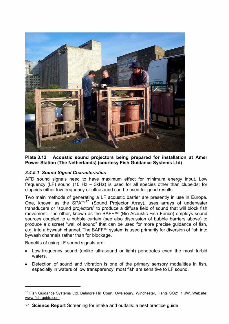
Science Report Screening for intake and outfalls: a best practice guide74
Plate 3.13 Acoustic sound projectors being prepared for installation at AmerPower Station (The Netherlands) (courtesy Fish Guidance Systems Ltd)
3.4.5.1 Sound Signal CharacteristicsAFD sound signals need to have maximum effect for minimum energy input. Lowfrequency (LF) sound (10 Hz – 3kHz) is used for all species other than clupeids; forclupeids either low frequency or ultrasound can be used for good results.Two main methods of generating a LF acoustic barrier are presently in use in Europe.One, known as the SPA17 (Sound Projector Array), uses arrays of underwatertransducers or “sound projectors” to produce a diffuse field of sound that will block fishmovement. The other, known as the BAFF™ (Bio-Acoustic Fish Fence) employs soundsources coupled to a bubble curtain (see also discussion of bubble barriers above) toproduce a discreet “wall of sound” that can be used for more precise guidance of fish,e.g. into a bywash channel. The BAFF system is used primarily for diversion of fish intobywash channels rather than for blockage.Benefits of using LF sound signals are:
• Low-frequency sound (unlike ultrasound or light) penetrates even the most turbidwaters.
• Detection of sound and vibration is one of the primary sensory modalities in fish,especially in waters of low transparency; most fish are sensitive to LF sound.
17 Fish Guidance Systems Ltd, Belmore Hill Court, Owslebury, Winchester, Hants SO21 1 JW. Website:www.fish-guide.com
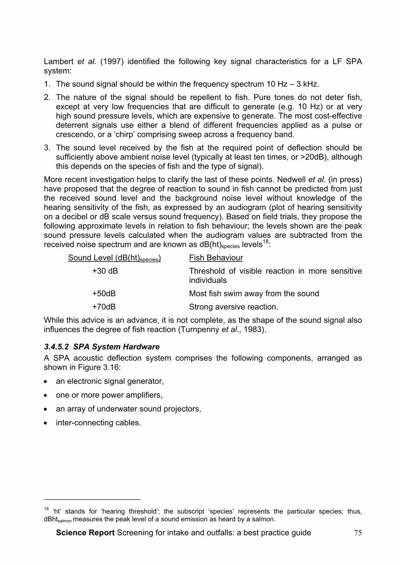
Science Report Screening for intake and outfalls: a best practice guide 75
Lambert et al. (1997) identified the following key signal characteristics for a LF SPAsystem:1. The sound signal should be within the frequency spectrum 10 Hz – 3 kHz.2. The nature of the signal should be repellent to fish. Pure tones do not deter fish,
except at very low frequencies that are difficult to generate (e.g. 10 Hz) or at veryhigh sound pressure levels, which are expensive to generate. The most cost-effectivedeterrent signals use either a blend of different frequencies applied as a pulse orcrescendo, or a ‘chirp’ comprising sweep across a frequency band.
3. The sound level received by the fish at the required point of deflection should besufficiently above ambient noise level (typically at least ten times, or >20dB), althoughthis depends on the species of fish and the type of signal).
More recent investigation helps to clarify the last of these points. Nedwell et al. (in press)have proposed that the degree of reaction to sound in fish cannot be predicted from justthe received sound level and the background noise level without knowledge of thehearing sensitivity of the fish, as expressed by an audiogram (plot of hearing sensitivityon a decibel or dB scale versus sound frequency). Based on field trials, they propose thefollowing approximate levels in relation to fish behaviour; the levels shown are the peaksound pressure levels calculated when the audiogram values are subtracted from thereceived noise spectrum and are known as dB(ht)species levels18:
Sound Level (dB(ht)species) Fish Behaviour+30 dB Threshold of visible reaction in more sensitive
individuals+50dB Most fish swim away from the sound+70dB Strong aversive reaction.
While this advice is an advance, it is not complete, as the shape of the sound signal alsoinfluences the degree of fish reaction (Turnpenny et al., 1983).
3.4.5.2 SPA System HardwareA SPA acoustic deflection system comprises the following components, arranged asshown in Figure 3.16:
• an electronic signal generator,
• one or more power amplifiers,
• an array of underwater sound projectors,
• inter-connecting cables.
18 ‘ht’ stands for ‘hearing threshold’; the subscript ‘species’ represents the particular species; thus,dBhtsalmon measures the peak level of a sound emission as heard by a salmon.

Science Report Screening for intake and outfalls: a best practice guide76
Audiogram for S. trutta and S. salar
80.0
90.0
100.0
110.0
120.0
130.0
140.0
150.0
10 100 1000
Frequency (Hz)
Soun
d pr
essu
re (d
B re
1 u
Pa)
Figure 3.15 Audiograms of Atlantic salmon (Salmo salar) (▪) and trout (S. trutta)(●) (Nedwell et al., 2003).
The system is analogous to a public address or domestic hi-fi system. The signal isusually recorded onto an EPROM-chip and the signal generator may contain a number ofthese, which can be manually selected or played at random or in rotation. One or morehigh-power audio amplifiers that are matched and filtered to suit the sound projectorsamplify the signal. The sound projectors are underwater transducers, analogous toloudspeakers. These are electromagnetic devices, with a piston-type arrangementconnected to a rubber diaphragm.As there is an air cavity behind the diaphragm, sound projectors are susceptible topressure change, increasing pressure tending to force the diaphragm inwards. This limitsthe throw of the diaphragm and must be compensated by a balancing pressure frombehind. Sound projectors are therefore either pre-pressurised to cope with the expectedoperating depth, or else have some form of pressure compensation device. The lattertype is best suited to use at fixed positions in tidal waters.
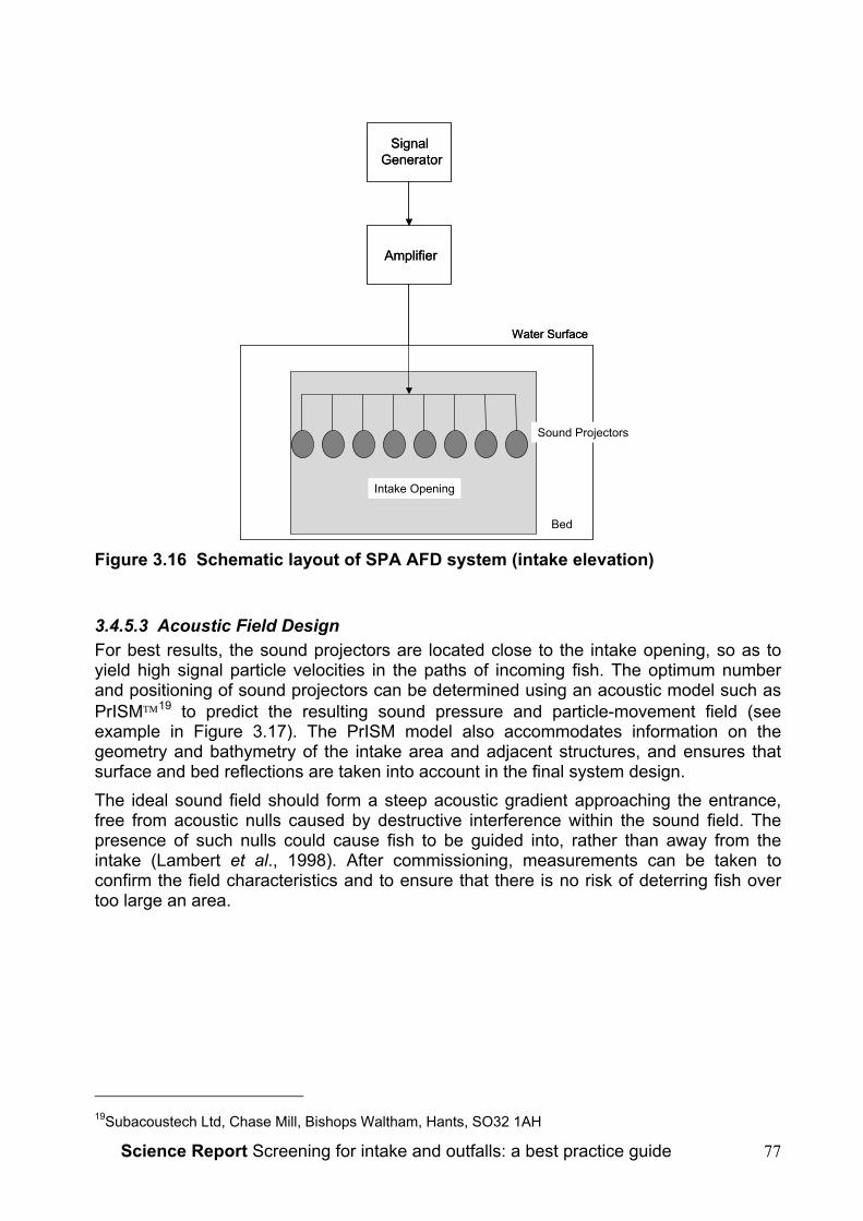
Science Report Screening for intake and outfalls: a best practice guide 77
Amplifier
Signal Generator
Sound Projectors
Water Surface
Intake Opening
Bed
Amplifier
Signal Generator
Sound Projectors
Water Surface
Intake Opening
Bed
Figure 3.16 Schematic layout of SPA AFD system (intake elevation)
3.4.5.3 Acoustic Field DesignFor best results, the sound projectors are located close to the intake opening, so as toyield high signal particle velocities in the paths of incoming fish. The optimum numberand positioning of sound projectors can be determined using an acoustic model such asPrISM19 to predict the resulting sound pressure and particle-movement field (seeexample in Figure 3.17). The PrISM model also accommodates information on thegeometry and bathymetry of the intake area and adjacent structures, and ensures thatsurface and bed reflections are taken into account in the final system design.The ideal sound field should form a steep acoustic gradient approaching the entrance,free from acoustic nulls caused by destructive interference within the sound field. Thepresence of such nulls could cause fish to be guided into, rather than away from theintake (Lambert et al., 1998). After commissioning, measurements can be taken toconfirm the field characteristics and to ensure that there is no risk of deterring fish overtoo large an area.
19Subacoustech Ltd, Chase Mill, Bishops Waltham, Hants, SO32 1AH

Science Report Screening for intake and outfalls: a best practice guide78
Figure 3.17 PrISM acoustic model of the acoustic deterrent field at Doel nuclearpower station, Belgium (Subacoustech Ltd).The lower part of the diagram shows the positions of the sound projector clusters aroundthe intake caisson. The five pale blue columns are dolphins that protect the offshore sideof the intake from damage by shipping. The upper part of the plot shows the acousticfield at 200 Hz, represented in units of dB re 1µPa. In practice, the model is run for avariety of tidal heights and over the full range of signal frequencies to be used.
3.4.5.4 Effectiveness of SPA Acoustic DeterrentsTurnpenny et al. (1998) showed that well designed LF SPA acoustic deterrent systemsoffer amongst the highest deflection efficiencies available from any type of behaviouralbarrier. Values of up to around 80% can be attained for many teleost species possessinga developed swimbladder, with recorded values of between 90% and 100% for the mostsensitive species such as herring. Table 3.2 shows test results from various installationsthat have been studied.The longest-running trials of a SPA system have been conducted at Doel Nuclear PowerStation on the Zeeschelde Estuary (Belgium). Since the installation of an FGS SPAsystem in 1997, regular monitoring has been carried out by Leuven University (Maes etal, 2004). As in most trials of this kind, comparisons have been made of the fishimpingement rates on alternate days with the sound system turned on or off. Althoughthe species captured have been primarily of estuarine or marine origin, quantities offreshwater fishes have been caught.As with other behavioural systems, habituation to the stimuli must be considered.Habituation, again, is not a problem with migratory or highly mobile fish, which are rarelyin contact with the sound for a long period. Nevertheless, it is an aspect relevant toresident fish populations, where fish may be in contact with the sound for extendedperiods. Acoustic deterrent signals are developed specifically to minimise the risk ofhabituation over a period of a few days at least (Turnpenny et al., 1993), but for moreextended exposure the deterrent signal may need to be altered at intervals (e.g. onceper day). Signal generators with multi-signal capability may be used for this purpose.
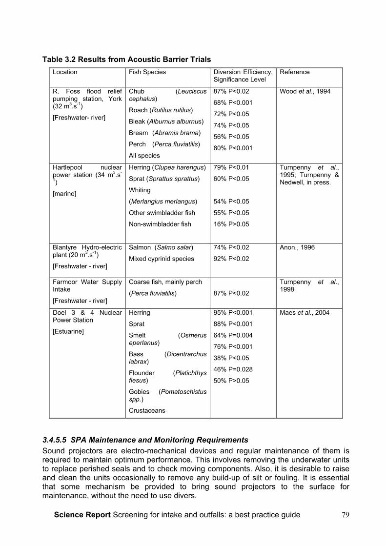
Science Report Screening for intake and outfalls: a best practice guide 79
Table 3.2 Results from Acoustic Barrier TrialsLocation Fish Species Diversion Efficiency,
Significance LevelReference
R. Foss flood reliefpumping station, York(32 m3.s-1)
[Freshwater- river]
Chub (Leuciscuscephalus)
Roach (Rutilus rutilus)
Bleak (Alburnus alburnus)
Bream (Abramis brama)
Perch (Perca fluviatilis)
All species
87% P<0.02
68% P<0.001
72% P<0.05
74% P<0.05
56% P<0.05
80% P<0.001
Wood et al., 1994
Hartlepool nuclearpower station (34 m3.s-
1)
[marine]
Herring (Clupea harengus)
Sprat (Sprattus sprattus)
Whiting
(Merlangius merlangus)
Other swimbladder fish
Non-swimbladder fish
79% P<0.01
60% P<0.05
54% P<0.05
55% P<0.05
16% P>0.05
Turnpenny et al.,1995; Turnpenny &Nedwell, in press.
Blantyre Hydro-electricplant (20 m3.s-1)
[Freshwater - river]
Salmon (Salmo salar)
Mixed cyprinid species
74% P<0.02
92% P<0.02
Anon., 1996
Farmoor Water SupplyIntake
[Freshwater - river]
Coarse fish, mainly perch
(Perca fluviatilis) 87% P<0.02
Turnpenny et al.,1998
Doel 3 & 4 NuclearPower Station
[Estuarine]
Herring
Sprat
Smelt (Osmeruseperlanus)
Bass (Dicentrarchuslabrax)
Flounder (Platichthysflesus)
Gobies (Pomatoschistusspp.)
Crustaceans
95% P<0.001
88% P<0.001
64% P=0.004
76% P<0.001
38% P<0.05
46% P=0.028
50% P>0.05
Maes et al., 2004
3.4.5.5 SPA Maintenance and Monitoring RequirementsSound projectors are electro-mechanical devices and regular maintenance of them isrequired to maintain optimum performance. This involves removing the underwater unitsto replace perished seals and to check moving components. Also, it is desirable to raiseand clean the units occasionally to remove any build-up of silt or fouling. It is essentialthat some mechanism be provided to bring sound projectors to the surface formaintenance, without the need to use divers.

Science Report Screening for intake and outfalls: a best practice guide80
As it is difficult to check the performance of submerged equipment, diagnostic units canbe attached to the shore-based electronics to monitor performance of the soundprojectors and associated electronics. These can be linked by telemetry systems tocontrol centres in the case of remote sites. Performance of the systems can then beelectronically logged and made available to regulatory enforcement staff.
3.4.5.6 Potential Public Noise NuisanceAlthough emitting frequencies that are within the human audible range, the location ofthe sound projectors below water generally prevents any audible acoustic propagationinto the air above. SPA systems are occasionally just audible from at the intake positionunder exceptionally quiet conditions, particularly if they have been mounted on anymetallic structures that project out from the water. A SPA system operated by theEnvironment Agency at the River Foss flood relief pumping station in York is located<50m from a city-centre hotel and has operated during pumping since 1995 withoutcomplaint.
3.4.5.7 Installations in the UKSPA AFD systems are widely used in the UK, with examples at locations shown in Table3.2. Also shown is other information about the specifications of the systems, theoperating environment and the types of fish to be protected.
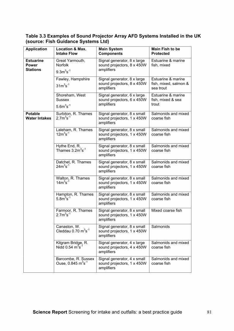
Science Report Screening for intake and outfalls: a best practice guide 81
Table 3.3 Examples of Sound Projector Array AFD Systems Installed in the UK(source: Fish Guidance Systems Ltd)Application Location & Max.
Intake FlowMain SystemComponents
Main Fish to beProtected
Great Yarmouth,Norfolk
9.3m3s-1
Signal generator, 8 x largesound projectors, 8 x 450Wamplifiers
Estuarine & marinefish, mixed
Fawley, Hampshire
31m3s-1
Signal generator, 8 x largesound projectors, 8 x 450Wamplifiers
Estuarine & marinefish, mixed, salmon &sea trout
EstuarinePowerStations
Shoreham, WestSussex
5.6m3s-1
Signal generator, 6 x largesound projectors, 6 x 450Wamplifiers
Estuarine & marinefish, mixed & seatrout
Surbiton, R. Thames2.7m3s-1
Signal generator, 8 x smallsound projectors, 1 x 450Wamplifiers
Salmonids and mixedcoarse fish
Laleham, R. Thames12m3s-1
Signal generator, 8 x smallsound projectors, 1 x 450Wamplifiers
Salmonids and mixedcoarse fish
Hythe End, R.Thames 3.2m3s-1
Signal generator, 8 x smallsound projectors, 1 x 450Wamplifiers
Salmonids and mixedcoarse fish
Datchet, R. Thames24m3s-1
Signal generator, 8 x smallsound projectors, 1 x 450Wamplifiers
Salmonids and mixedcoarse fish
Walton, R. Thames14m3s-1
Signal generator, 8 x smallsound projectors, 1 x 450Wamplifiers
Salmonids and mixedcoarse fish
Hampton, R. Thames5.8m3s-1
Signal generator, 8 x smallsound projectors, 1 x 450Wamplifiers
Salmonids and mixedcoarse fish
Farmoor, R. Thames2.7m3s-1
Signal generator, 8 x smallsound projectors, 1 x 450Wamplifiers
Mixed coarse fish
Canaston, W.Cleddau 0.70 m3s-1
Signal generator, 8 x smallsound projectors, 1 x 450Wamplifiers
Salmonids
Kilgram Bridge, R.Nidd 0.54 m3s-1
Signal generator, 4 x largesound projectors, 4 x 450Wamplifiers
Salmonids and mixedcoarse fish
PotableWater Intakes
Barcombe, R. SussexOuse, 0.845 m3s-1
Signal generator, 4 x smallsound projectors, 1 x 450Wamplifiers
Salmonids and mixedcoarse fish

Science Report Screening for intake and outfalls: a best practice guide82
3.4.5.8 Evanescent Sound: The BioAcoustic Fish Fence (BAFF)An evanescent (non-propagating) sound field is one that decays rapidly with distancefrom its source. The Bio-Acoustic Fish Fence (BAFF™) is a proprietary product of FishGuidance Systems Ltd (FGS) of Southampton, England that uses a combination of asound source and a bubble curtain to create a field that is largely contained within thebubble sheet (Nedwell and Turnpenny, 1997). Physically, it comprises anelectromagnetic or pneumatic sound transducer coupled to a bubble-sheet generator,causing sound waves to propagate within the rising curtain of bubbles. The sound iscontained within the bubble curtain as a result of refraction, since the velocity of sound ina bubble-water mixture differs from that in either water or air alone. The sound levelinside the bubble curtain may be as high as 170 dB re 1µPa, typically decaying to 5% ofthis value within 0.5-1 m from the bubble sheet (Figure 3.18). It can be deployed in muchthe same way as a standard bubble curtain, but its effectiveness as a fish barrier isgreatly enhanced by the addition of a repellent sound signal. The characteristics of thesound signals are similar to those used in SPA systems, i.e. within the 20-500 Hzfrequency range and using frequency or amplitude sweeps. Typically, the BAFF isused to divert fish from a major flow, e.g. entering a turbine, into the minor flow of abywash channel. Recently, the Illinois Natural History Survey have conducted trials of theBAFF in a concrete raceway to assess its effectiveness as a barrier to the migration ofinvasive Asian carp species Hypophthalmichthys nobilis (Taylor et al., in press). Initialtrials using a 20-500Hz signal yielded only moderate performance, with 56% ofapproaches being successfully repelled. The signal was subsequently replaced by a 20-2000Hz signal, which increased deflection efficiency to 95%. This was comparable toresults obtained with the GFFB electrical barrier in parallel tests.
Concrete ballastConcrete ballast
Sound generatorsSound generators
Air curtainAir curtain
Air supply and cable channelAir supply and cable channel
Sound contoursSound contours
Water surfaceWater surface
Concrete ballastConcrete ballast
Sound generatorsSound generators
Air curtainAir curtain
Air supply and cable channelAir supply and cable channel
Sound contoursSound contours
Water surfaceWater surface
Figure3.18 Schematic of BAFF acoustic bubble curtain (Fish Guidance Systems Ltd)

Science Report Screening for intake and outfalls: a best practice guide 83
3.4.5.9 Installations in the UKInvestigations of a BAFF angled at 15o system across a small (~5m width) mill streamof the River Frome (Dorset) yielded deflection rate of 20.3-43.8% in daylight and 72.9-73.8% in darkness with Atlantic salmon smolts (Welton et al., 2002). The sound isgenerated pneumatically, with frequencies in the 50-600Hz band. A larger (24 m-long)BAFF placed at an angle across the main river to divert descending smolts into the millstream for census purposes has regularly achieved efficiencies of 95-98% (S. Welton,personal communication). The river depth along the BAFF line is about 1.2m. The trialswere conducted as part of an Environment Agency research programme. The betterperformance of the larger BAFF may have been due to the larger ‘bywash’ created bythe entrance to the millstream. Observations at the BAFF located in the millstreamdemonstrated that many of the fish were effectively diverted by the BAFF but then turnedback at the bywash entrance, owing perhaps to inadequate attraction flow. Such fishwould often make several attempts, circling in the area upstream of the BAFF and finally‘rushing’ the bubble curtain and passing through. A more detailed analysis of fishbehaviour in front of a BAFF is provided by Turnpenny et al. (2002, in press), based onobservations of fish fitted with float-tags.A pneumatic BAFF is installed at a small hydropower scheme at Backbarrow on the R.Leven (Cumbria). It was installed in the headrace canal, principally to divert salmonidsmolts into a bywash, which uses between 2 and 5% of the turbine flow as attractionflow. It also operates with frequencies in the 50-600Hz band. Performance trials havebeen carried out by the Environment Agency, by placing a rotary-screw smolt trap in theflow behind the BAFF to sample fish passing through the air curtain and simultaneouslycounting fish entering the bywash (Spiby, 2004). Bywash monitoring was carried outusing a submerged video camera in the bywash entrance with infra-red illumination,connected to a video recorder. Observations were made over 44 days during the springof 2003, during which time 109 fish were recorded. These were distributed as follows:
• 56.9% entered the bywash (video)
• 30.3% swam back into the headrace (video)
• 5.5% uncertain- either entered bywash or swam back into headrace (video)
• 7.3% passed through BAFF (rotary screw trap).Spiby proposed a best estimate of 92.7% of fish being prevented from entering theturbine, although as only 56.9% were seen to enter the bywash, the true deflectionefficiency may have been between 56.9% and 92.7%. Only 2.7% of the 7.3% of fishestimated to pass through the turbine were smolts. The author drew attention to anumber of limitations of the study, particularly with regard to the quality of videomonitoring and the performance of the trap under low flow or heavy weed conditions andrecommended that further proving trials should be conducted.
3.4.5.10 InfrasoundWhereas the acoustic techniques described above may contain frequencies extendingdown into the infrasound (<20Hz) region, true infrasound devices are designed to emitprimarily in this waveband. A review is given by Sand et al. (2001). Normally, the soundis generated by a mechanical, motor-driven device, driving pistons to generate highparticle velocities in the region of the source. For Atlantic salmon smolts, soundintensities above 10-1ms-2 at 10Hz are an effective deterrent and have been usedsuccessfully to block channels. Sand et al. mention mechanical reliability and metal
Science Report Screening for intake and outfalls: a best practice guide84
fatigue problems with the source devices that have limited their practicability in the pastbut these may be reduced eliminated with further development. A particular interest withinfrasound lies in the finding that adult silver eels (Anguilla anguilla) migrations weresuccessfully influenced by an infrasound source in river trials. Audiogram measurementshave shown that eels are most sensitive to sound pressure at frequencies centering on90Hz but to vibrations of around 40Hz (Jerkø et al, 1989). Given the relatively limitedrange of screening methods suitable for eels, particularly in the hydropower and thermalpower context, infrasound or low frequency sound merits further investigation.
3.4.5.11 Ultrasound Transducer ArraysUltrasound systems have so far been used mainly in north America, where arrays ofultrasound transmitters have been fitted around intake structures to repel shad andherring species (Carlson, 1995). Ultrasound may be worth considering for some UKapplications, for example where shad are present, although shad also show a goodsensitivity to LF systems, to which clupeids are more sensitive than ultrasound (Mann etal., 1997). The latter have the advantage of also repelling non-clupeid species.
3.4.5.12 Acoustic AttractionWhile most studies have reported the use of acoustic stimuli as a fish deterrent, Patricket al. (2001) demonstrated in tank experiments that eels (Anguilla rostrata) wereattracted towards a transducer emitting a “complex signal” containing frequencies of<1000Hz. The signal characteristics were not described beyond this and the levelsinvolved are not stated, although the source level was < 190µPa @1m. The authorssuggest that sound may have some potential for attracting eels towards bywashes.
3.4.5.13 Design and Operational Best PracticeAFD systems should be installed according to manufacturers’ specifications. Importantconsiderations are:
• Background noise levels should be measured prior to AFD specification to ensurethat the signal is not going to be masked by noise from pumps, turbines, etc..
• For SPA systems, acoustic modelling (e.g. using PrISM) is essential for all butthe smallest applications. This should also be used to ensure that the spread ofthe sound field is not excessive, which might interfere with movements ofmigratory fish or cause local loss of habitat. Levels should also be measured atcommissioning to validate predicted values.
• Diagnostic/monitoring systems should be fitted so that the performance of theunderwater equipment can be monitored e.g. from a plant control room. Someform of indicator should be fitted at the abstraction point to show the operationalstatus to operational and enforcement staff.
• Provision should be made for retrieving the underwater equipment for servicing.
• Some redundancy (i.e. using more sound sources than are strictly needed) isdesirable to allow for sound projector failures.
• The equipment requires regular maintenance and service intervals should bedisplayed and logged in the plant control room.
• Back-up power or interlocks with pump controls may need to be provided toensure that pumping does not occur when the system has lost power.

Science Report Screening for intake and outfalls: a best practice guide 85
• In the case of the BAFF, the recommendations made regarding bubble curtains(see above) also apply, as do physical limitations regarding water depth and flow.
3.4.5.14 ApplicationsAcoustic fish deterrents are particularly suited to high flow rate intakes where positiveexclusion screens are impractical owing to the hydraulic head loss or the risk of screenblockage and where <100% exclusion is acceptable. Electrical power is required, whichmakes them unsuitable for unpowered, remote sites. There are more than sixtyinstallations in Britain, Europe and North America, with applications including potablewater intakes, flood relief pumping stations, thermal and hydroelectric power plant and afish census station. SPA and BAFF are also being tested in the USA for possible useas invasive species barriers against the spread of Asian carp species, with excellentresults to date (Taylor et al., in press).Since estuarine and coastal power stations tend to draw in large quantities of hearing-sensitive pelagic species, such as sprat, herring and smelt, AFDs have been found toyield large reductions in catch of these species. Systems have recently been installed inthe UK at new CCGT power stations at Shoreham (W. Sussex) and Great Yarmouth(Norfolk) and retrofitted to Fawley Power Station (Hampshire). These stations alsooperate fish return techniques that put back to the wild any hearing-insensitive animalsthat get past the AFD system. These are mainly eels, flatfishes and other benthicspecies, as well as shrimps and crabs. Post-commissioning surveys conducted atShoreham in the three years since its completion suggest that it has the lowest fish catchof any major British coastal power station.
3.4.5.15 Species and LifestagesAFD systems are best suited to fishes with moderate to high hearing sensitivity. Bestresults are obtained with hearing specialists, e.g. clupeids (herrings and shads),cyprinids, other sensitive species including smelt (Osmerus eperlanus) and bass(Dicentrarchus labrax). Non-specialist species with a fully developed swim bladder arealso amenable to AFD guidance, e.g. salmonids and gadoids. Species with a poorlydeveloped or no swim bladder, e.g. most benthic species, such as flatfish, can bedeterred using high sound levels but this may not be cost-effective. In particular, eels andlampreys show very little reaction to AFD signals, although the use of infrasound meritsfurther research.
3.4.5.16 Ease of RetrofittingAFD systems lend themselves to retrofitting, requiring very little engineering work toinstall. As well as being used to upgrade fish protection on older intakes, for example byThames Water Utilities Ltd on R. Thames intakes, Yorkshire Water plc have used themfor fish diversion at temporary water abstractions.
3.4.6 Light-based SystemsLight is used in two ways to reduce entrapment. The first is to illuminate physical orbehavioural screens to make them more visible so that fish can orientate themselves inrelation to the flow (using the optomotor response); the second is to use the stimulus oflight in its own right to either attract or repel.The fish deterrent effects of light were first studied in the 1950s when Brett andMacKinnon (1953) used light to restrict the movement of animals in a canal. Although
Science Report Screening for intake and outfalls: a best practice guide86
these early tests were not extensive there were two important findings: firstly, thatdifferent reactions were displayed by different species and secondly that flashing lightswere more effective at eliciting a response than continuous light (OTA, 1995).It is commonly found when using physical screens, greatest impingement occurs duringhours of darkness. Up to 97% of young fish will be entrained at night (Pavlov, 1989).During hours of darkness in particular, artificial lighting will allow improved orientation offish and therefore reduced entrainment. This effect may be further enhanced by carefulpositioning of light sources behind structural elements to provide maximum visualcontrast by throwing the structure into silhouette (Turnpenny, 1998). With the addition oflights to an intake structure Pavlov achieved a reduction of entrainment of youngcyprinids and percids of up to 91%. The effectiveness of this behavioural system,however, varies with species with up to 100% deterrence being seen for perch (Percafluviatilis) and ruffe (Gymnocephalus cernua) whereas entrapment was increased withillumination in the case of three-spined-sticklebacks (Gasterosteus aculeatus)(Hadderingh, 1982). Light can therefore act as either a repellent or an attractant todifferent species.To minimise light pollution and to achieve the highest possible effectiveness it isnecessary to submerge the light source. This results in a significant increase in thecapital and maintenance cost due to necessary frequent cleaning of lamps requiring amechanical recovery system. The most common positioning of lamps is in an arc on thebed around the intake entrance ensuring water velocities at this point are low enough toallow fish to escape (Turnpenny, 1998). The angle of positioning of the lamps is alsoimportant with an upwards tilt of 40-45° having been found to be most effective (Johnsonet al., 2001).
3.4.6.1 Constant IlluminationContinuous illumination is not the optimum method for most species but is useful in thecase of eels. This approach has been tested extensively in the Netherlands (Hadderinghand Smythe, 1997). Eels show strong phototaxis and positive rheotaxis (orientation intocurrents). Light can therefore be used to discourage the tendency of eels to follow waterflow. The lights can be incandescent lights, mercury vapour lights or fluorescent lights.Trials have mainly used the latter (specified as 36W, PL-L Philips, spectrum with peaksat 440, 550 and 610nm). Deflection rates of up to 74% have been observed at somethermal and hydroelectric power stations.
3.4.6.2 Strobe lightsStrobe lights generally give better results than continuous illumination. Most experimentshave again centred on the eel. Patrick et al. (1982, 2001) conducted experiments oneels. The first study was to determine if strobe lights could be used to deter eels fromentering a turbine unit during its shutdown period. The second involved initial laboratorytests followed by field trials at a fish ladder. Both investigations showed a reduction of eelmovement of between 65% and 92%. The laboratory tests in the second study usedflash frequencies from 66 to 1090 flashes per minute (FPM) and showed that all wereeffecting in repelling eels. The fish ladder trials used a flash rate of >800 FPM. Thethreshold light level for eel repulsion was found to be ≥0.1µEm-2s-1 (≥5 lux).Work has also been carried out on other species, including white perch (Moroneamericana), spot (Leiostomus xanthurus) and Atlantic menhaden (Brevoortia tyrannus)although the level of effectiveness and the necessary flash rate varied with species(Sager et al., 1987). Other species investigated by Patrick et al.(1982) included Atlantic

Science Report Screening for intake and outfalls: a best practice guide 87
salmon, which were also repelled by strobe lights. Flash rates of 300 FPM appeared tobe most effective. Johnson et al (2001) also found 300 FPM to be effective in achievingvertical displacement of steelhead trout (Oncorhynchus mykiss); their concept was toshift the fish upwards in the water column away from an intake to reduce entrainment.Tests with kokanee (O. nerka) found flash rates of 300, 360 and 450 FPM all to be aneffective repellent, even when light levels were <0.00016 lux above ambient light levels;the repellent effect continued throughout the longest test duration of 5h 50min (Maiolie etal, 2001).The success of using strobe lights as a deterrent has been found to be site specific,indicating that hydraulic and environmental conditions have an effect (OTA, 1995).Strobe lights may prove to be more effective when used in conjunction with other formsof behavioural and physical screening systems. In particular bubble screens /strobe lightcombinations work well for some species, e.g. alewife (Alosa pseudoharengus), smelt(Osmerus mordax) and gizzard shad (Dorosoma cepedianum) (Patrick et al., 1985). Thiscombination was also tested in the UK at Walton-on-Thames raw water intake, where areduction of 62.5% entrainment of salmon smolts was observed (Solomon, 1992).In earlier systems a problem with the short lifespan of the xenon discharge tube madeoperation difficult. Modern tubes however, will last for a year or more when correctlydriven. New models of strobe lights are now available with greater flexibility in flash rate,light intensity and sequencing via a laptop computer. This will allow for easier adjustmentof the lights without the need for removal, therefore reducing costs (Johnson et al.,2001).
3.4.6.3 Design and Operational Best PracticeThere has been very little use of this approach in the UK to date and therefore ‘bestpractice’ is unclear. Important issues are:
• Water clarity must be high.
• A lamp retrieval mechanism must be installed.
• Adequate testing is required to optimize the flash rate when strobes are used;there is a risk of attracting rather than repelling fish at some flash rates. Flashrates of ≥300 FPM appear to work best with a range of species.
• Some redundancy (i.e. using more lights than are strictly needed) is desirable toallow for lamp failures.
• Warning systems (e.g. via telemetry links) should be provided to inform plantoperators of failure.
• The equipment requires regular maintenance and service intervals should bedisplayed and logged in the plant control room.
• Visible indicators of the operational status (e.g. number lamps operating versusfailures) should be displayed at or close to the intake to inform operational andenforcement personnel.
• Back-up power or interlocks with pump controls may need to be provided toensure that pumping does not occur when the system has lost power.
The use of ‘high-tech’ computer control systems appears to enhance flexibility andcontrol of the systems and looks promising.
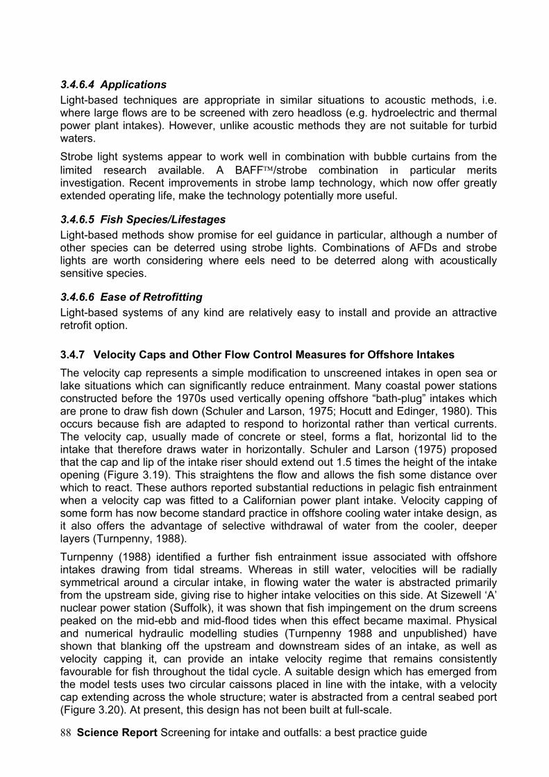
Science Report Screening for intake and outfalls: a best practice guide88
3.4.6.4 ApplicationsLight-based techniques are appropriate in similar situations to acoustic methods, i.e.where large flows are to be screened with zero headloss (e.g. hydroelectric and thermalpower plant intakes). However, unlike acoustic methods they are not suitable for turbidwaters.Strobe light systems appear to work well in combination with bubble curtains from thelimited research available. A BAFF/strobe combination in particular meritsinvestigation. Recent improvements in strobe lamp technology, which now offer greatlyextended operating life, make the technology potentially more useful.
3.4.6.5 Fish Species/LifestagesLight-based methods show promise for eel guidance in particular, although a number ofother species can be deterred using strobe lights. Combinations of AFDs and strobelights are worth considering where eels need to be deterred along with acousticallysensitive species.
3.4.6.6 Ease of RetrofittingLight-based systems of any kind are relatively easy to install and provide an attractiveretrofit option.
3.4.7 Velocity Caps and Other Flow Control Measures for Offshore IntakesThe velocity cap represents a simple modification to unscreened intakes in open sea orlake situations which can significantly reduce entrainment. Many coastal power stationsconstructed before the 1970s used vertically opening offshore “bath-plug” intakes whichare prone to draw fish down (Schuler and Larson, 1975; Hocutt and Edinger, 1980). Thisoccurs because fish are adapted to respond to horizontal rather than vertical currents.The velocity cap, usually made of concrete or steel, forms a flat, horizontal lid to theintake that therefore draws water in horizontally. Schuler and Larson (1975) proposedthat the cap and lip of the intake riser should extend out 1.5 times the height of the intakeopening (Figure 3.19). This straightens the flow and allows the fish some distance overwhich to react. These authors reported substantial reductions in pelagic fish entrainmentwhen a velocity cap was fitted to a Californian power plant intake. Velocity capping ofsome form has now become standard practice in offshore cooling water intake design, asit also offers the advantage of selective withdrawal of water from the cooler, deeperlayers (Turnpenny, 1988).Turnpenny (1988) identified a further fish entrainment issue associated with offshoreintakes drawing from tidal streams. Whereas in still water, velocities will be radiallysymmetrical around a circular intake, in flowing water the water is abstracted primarilyfrom the upstream side, giving rise to higher intake velocities on this side. At Sizewell ‘A’nuclear power station (Suffolk), it was shown that fish impingement on the drum screenspeaked on the mid-ebb and mid-flood tides when this effect became maximal. Physicaland numerical hydraulic modelling studies (Turnpenny 1988 and unpublished) haveshown that blanking off the upstream and downstream sides of an intake, as well asvelocity capping it, can provide an intake velocity regime that remains consistentlyfavourable for fish throughout the tidal cycle. A suitable design which has emerged fromthe model tests uses two circular caissons placed in line with the intake, with a velocitycap extending across the whole structure; water is abstracted from a central seabed port(Figure 3.20). At present, this design has not been built at full-scale.

Science Report Screening for intake and outfalls: a best practice guide 89
Figure 3.19 The velocity cap: (a) section of uncapped intake showing verticaldraw-down pattern, (b) section of capped intake showing horizontal flow pattern,(c) as (b) but showing critical relationship between vertical opening [x] and lengthof horizontal entrance [1.5x] for fish reactions (after Schuler and Larson, 1975).

Science Report Screening for intake and outfalls: a best practice guide90
Figure 3.20 Concept design for a low-velocity, side-entry offshore intake structurewith velocity cap, based on physical and hydraulic model tests carried out atFawley Aquatic Research laboratories (Turnpenny, 1988 and unpublished). A andB are the cylindrical caissons. Water enters C.
3.4.7.1 Design and Operational Best Practice• Where it is not feasible to use more effective fish screening methods such as
PWWC screens, offshore intakes should be designed to ensure that flows are kepthorizontal and that intake velocities are not unduly influenced by tidal movement orriver flow. These conditions are best achieved by fitting a velocity cap and lateralintake ports.
• Offshore intakes are usually costly structures and it is strongly recommended thatphysical or numerical hydraulic modelling studies are undertaken to demonstratethat the above intake flow conditions are attained.
• Experience at UK sites where velocity caps are present has shown that fishentrainment remains a problem and velocity caps are therefore not in themselves asolution. Other measures, including use of side-entry, of behavioural deterrents andonshore fish return systems need to be considered.
3.4.7.2 ApplicationsThe measures described should be applied to all offshore intakes and mid-river intakeswhere fish are not protected by more stringent screening measures such as PWWCscreens.
Science Report Screening for intake and outfalls: a best practice guide 91
3.4.7.3 Fish Species/LifestagesVelocity caps are most important for the protection of pelagic species or lifestages thatare found in the upper water column. At most power plant intakes, pelagic fish areusually overwhelmingly the major entrained component. Side-entry devices areappropriate to all species and lifestages.
3.4.7.4 Installations in the UKMany UK offshore intakes have capped intake structures but few can be described astrue velocity caps as described by Schuler and Larson (1975). Dungeness ‘B’ (Kent) andSizewell ‘B’ (Suffolk) nuclear power stations both have velocity caps, as doesStallingborough power station (Humber estuary). None are known to have any devicedeliberately to control the radial distribution of intake flow for the purpose of reducingentrainment.
3.4.7.5 Ease of RetrofittingSome attempts to reduce vertical draw have been made on offshore intakes. AtDungeness ‘A’ power station, the top bars of the original caged structure were blankedoff with concrete to reduce vertical flow, although this does not form a true velocity cap. Abadly designed intake (from the fish protection point of view) cannot easily be remediedwithout major civil works. Acoustic fish deterrents and fish return systems have so farproved the best remediation option for such cases.
3.5 Other Behavioural Guidance TechniquesThere are examples of other interesting techniques that have been investigated in NorthAmerica and which may have some potential for use in Britain.
3.5.1 Turbulent Attraction FlowThe turbulent attraction flow concept attempts to mimic natural river turbulence cues thatdownstream migrating fish use to follow currents (Coutant, 2001). Any stream or riverhas turbulences along its watercourse due to interactions with the topographic featuresof the riverbed. These turbulences alter the velocity, direction and pressure of the waterflow. One main form of turbulence found in a river is a ‘turbulent burst’, which is a high-speed ejection of water and suspended solids as water passes an obstruction. Rows ofvortices are another common feature created in the wake behind solid objects. It isbelieved that migrating juvenile salmon use the enhanced water velocities found withinthese turbulences to assist in their downstream migration. While high turbulenceintensities and small vortex diameters can be damaging to fish, low intensities create anattractive stimulus.It follows from this that low turbulence intensities can be created to attract fish to abywash entrance. A trail of turbulence can be engineered either actively or passively.Passive devices are structures such as concrete cylinders that are placed on theriverbed. When placed at intervals, a chain of vortices and increasing velocity can begenerated, leading into the bywash. Where there is insufficient momentum in the water,active devices may be necessary. Turbulence can be actively created using devicessuch as a pumped water jet, propeller or paddle wheel suspended midway in the watercolumn (Coutant, 2001).A prototype ‘current inducer’ was tested by Truebe et al. (1997, 1998). A mechanicallygenerated current was created to direct Atlantic salmon to a surface bywash system.
Science Report Screening for intake and outfalls: a best practice guide92
Prior to installation of the device, natural flow was minimal within the area and fish weredrawn towards the turbine intake. The current was generated by two 2-hp, low-speedelectrically driven propellers. The system resulted in a bypass efficiency of up to 93%(Coutant, 2001).Turbulence induction may be most useful as an adjunct to other behavioural and positiveexclusion screening technologies. This area deserves further research to establishdesign criteria and its effectiveness with different fish species and lifestages.
3.5.2 Surface CollectorsThis fish diversion technique, used at large dams, is based upon the natural tendency ofsalmonid smolts to migrate in the surface layers of the water column, allowing fish to beskimmed off by surface bypasses or ‘collectors’. The surface collectors are located onthe dam and fish can be either bypassed around the dam or transported downstream intrucks or barges.Until very recently, surface collectors have been implemented in the field only asprototypes. Prototype trials have been carried out by the US Army Corps of Engineers inthe Pacific Northwest region of the USA and are the source for the following information(Dankel, 1999; Lemon, 2000).One of the largest of these prototypes was installed at the Bonneville Dam on theColumbia River, Oregon in 1996. The main structure of the dam houses ten Kaplanturbine. The surface collector has 12 modules spanning four of the ten turbine bays. Themodules are 21 m high, 8.4 m wide and 7 m deep. An attraction flow is provided bymeans of current inducers located within each unit. The system then diverts fish towardsan existing fish screen, which channels them around the dam. The surface collectorsystem is expected to divert 50-60% of approaching fish whereas the combination of thesurface collector and the existing screen system should achieve 90% diversion.In 2001 a seven-year prototype trial surface collector screen was removed from theRocky Reach hydroelectric project on the Columbia River (Plates 3.14, 3.15). It has beenreplaced with one of the first permanent systems, which began full operation in April2003 (www.chelanpud.org)20. The system is made up of two parts. First is the collectorsystem itself which uses 29 pumps to create a strong current in the upper 60 feet of theflow to attract fish away from the turbine flow into the bypass system. The bypass systemconsists of a 7.7 m diameter tube which passes through the dam and extends some1,380 m around the back of the powerhouse and 0.5 km down the east bank of the river.The total trip for fish passing through the system is 6 to 8 minutes long. The system cost$112 million to construct; this is expected to be recovered by the $400 million savingwithin 15 years due to a reduction in spill loss. The system is expected to achieve a 98%fish survival rate.
20 Chelan County Public Utilities District – Rocky Reach Hydro Project

Science Report Screening for intake and outfalls: a best practice guide 93
Plate 3.14 Rocky Reach dam with the powerhouse on the left and the bypass pipein the bottom right (Chelan County PUD).
Plate 3.15 The bypass pipe traversing the dam (Chelan County PUD).The system is still being monitored in the field and needs further investigation both in thefield and the laboratory before widespread installation.
3.5.3 Eel BypassesOne further technique of interest is the eel bypass channel. An example is found atBackbarrow hydropower scheme on the R. Leven in Cumbria (Spiby, 2004), which isclaimed to be based on a traditional eel fishing method. The bypass comprises a troughset in the floor of the headrace at an angle of 60o to the flow, with a 20 cm high wall onthe downstream side (Plate 3.15) and a 20 cm bywash pipe at its downstream end. Theeffectiveness of this bypass is not known. Similar arrangements are reported in Richkus(2001), who cites French and German examples of this method used for European eel(Anguilla anguilla) diversion (Travade, unpublished and Rathke, 1993, unreferenced).The French example refers to the Halsou hydroelectric project in the Pyrenees, where adeep trough is set into the floor of the headrace upstream of the trash racks. Thisconnects to a bywash, which draws 3-5% of the turbine flow. From radio-tracking studies,it was estimated that between 50% and 80% of eels used the deep bypass. In Germany,in one case the eel bypass was formed by a steel half-pipe set into the floor of a turbinespiral chamber. When fully opened, the pipe carried 1000 Ls-1 (proportion of total turbineflow unspecified). Using farmed (presumably yellow) eels, 41% of eels released used the
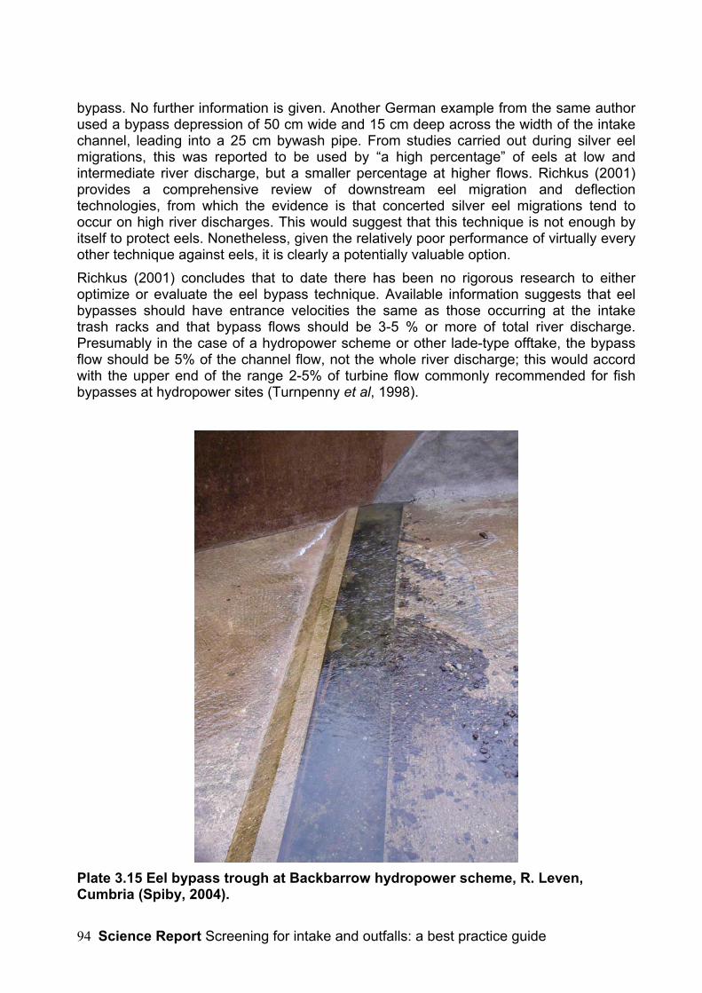
Science Report Screening for intake and outfalls: a best practice guide94
bypass. No further information is given. Another German example from the same authorused a bypass depression of 50 cm wide and 15 cm deep across the width of the intakechannel, leading into a 25 cm bywash pipe. From studies carried out during silver eelmigrations, this was reported to be used by “a high percentage” of eels at low andintermediate river discharge, but a smaller percentage at higher flows. Richkus (2001)provides a comprehensive review of downstream eel migration and deflectiontechnologies, from which the evidence is that concerted silver eel migrations tend tooccur on high river discharges. This would suggest that this technique is not enough byitself to protect eels. Nonetheless, given the relatively poor performance of virtually everyother technique against eels, it is clearly a potentially valuable option.Richkus (2001) concludes that to date there has been no rigorous research to eitheroptimize or evaluate the eel bypass technique. Available information suggests that eelbypasses should have entrance velocities the same as those occurring at the intaketrash racks and that bypass flows should be 3-5 % or more of total river discharge.Presumably in the case of a hydropower scheme or other lade-type offtake, the bypassflow should be 5% of the channel flow, not the whole river discharge; this would accordwith the upper end of the range 2-5% of turbine flow commonly recommended for fishbypasses at hydropower sites (Turnpenny et al, 1998).
Plate 3.15 Eel bypass trough at Backbarrow hydropower scheme, R. Leven,Cumbria (Spiby, 2004).

Science Report Screening for intake and outfalls: a best practice guide 95
3.6 Outfall Screening
3.6.1 IntroductionThe screening of outfalls is for one or both of two purposes:1. to prevent upstream swimming fishes that may be attracted to a discharge flow from
entering the discharge or being distracted from the natural flow;2. to avoid losses of fish stock from a fish farm, reservoir or pond outlet into a natural
watercourse.Outfall screens are limited to two types that have been shown to be effective: mechanicalmesh or bar screens and electric screens or ‘hecks’. Acoustic methods, and possiblyother behavioural methods, have been attempted to block upstream movements, butlargely unsuccessfully. The lack of reliably good results appears to be because of thestrong motivation of fish as they migrate towards their spawning grounds: stimuli thatmight under other circumstances deter them become ineffective.Screening against up-migrating elvers has not traditionally been practiced but must nowbe considered, in the light of the current declining status of eel stocks. This is probablynot an issue at hydropower sites or other large, high velocity outfalls that elvers wouldfind difficult to ascend, but may be at low velocity outfalls. Swimming speedmeasurements for elvers of A. anguilla made as part of the Environment Agency NationalR & D Project No. W2-049 “Swimming Speeds in Fish” indicate that upstream-migratingelvers can attain an average burst speed of 0.5 ms-1, suggesting that the dischargevelocity would need to be at least 0.7-0.8 ms-1 to ensure that elvers could not ascend.However, this in itself could attract larger migratory fish and therefore these would needto be screened out. There are options other than screening; for example, since eelscannot leap, raising the discharge point above flood water level would be effective.
3.6.2 Positive exclusion ScreensFrom the fish protection point of view, there are a number of criteria for effective outfallscreening:
3.6.2.1 Mesh or Bar SpacingThe screen should have mesh or bar spacings suited to the sizes of fish to be excluded.Standard sizes are e.g. 40 mm horizontal spacings (free gap) for adult Atlantic salmon or30 mm for adult sea trout (Anon., 1995). Smaller spacings may be required for otherspecies (see section 3.1). Square or rectangular bar is preferable to round bar for fishscreens.Fish farm outfalls represent a special case, where screening needs to be provided tokeep farm fish inside the farm without allowing escapes to the watercourse. In this case,the screening should reflect the sizes of fish held on the farm. Normally, however, thisfunction is provided by fish screens located at strategic points around the farm, and notnecessarily at the final outfall position. An outfall screen suited to the river fish will thenneed to be provided at the point of outfall.
3.6.2.2 Screen LocationOutfall screens should be located at the most downstream point of the discharge; failureto do this can create blind alleys where fish become trapped and possibly vulnerable to

Science Report Screening for intake and outfalls: a best practice guide96
poachers. The position and alignment of the screen can be arranged to guide fishupstream towards the preferred route, e.g. the main river channel or the entrance to afish pass. This is particularly important where screens are placed across hydroelectrictailraces.
3.6.2.3 Working DepthWhere screens are not e.g. fitted to cover the end of a pipe or tunnel but are placedacross an open channel, the height and the extent of the screen should take account ofthe local topography and foreseeable flood levels; otherwise fish may circumvent thescreens during floods and become trapped when the level falls. The same provisoapplies to screens used to retain fish on fish farms.
3.6.3 Electric BarriersElectric barriers or hecks have been used for many years to prevent the ascent of fishinto hydroelectric tailraces and they are generally considered to work well for thepurpose. This method is sometimes preferred to positive exclusion screening at low-headhydro sites, where the additional loss of head caused by the screens may be significant.Most of the MAFF-type electric screens (see section 3.3) have now, however, beenremoved owing to safety concerns.The GFFB system described in section 3.3 is also used for outfall screening but isconsidered to be a safer option, for reasons discussed in section 3.3. The GFFB can befitted as an electrode array running across the bed (Figure 3.21) or as an annular arrayfixed within the confines of a tunnel. It is found to work best with a minimum watervelocity of 0.6-0.9 m.s-1, which causes fish to be pushed away as they cross the electricfield, and with a maximum operating depth of about 5 m.In an investigation carried out at the Pere Marquette River (Rozich, 1989) the GFFBsystem was found to be effective in preventing upstream sea lamprey migration whilststill allowing downstream penetration of steelhead adults and smolts and chinook smoltswith no injury.
Figure 3.21 Diagram showing fish movement in response to the GFFB electric fishbarrier. In the diagram, the energisation voltage of the electrode strips increasesfrom right to left of the diagram. The fish turn away at a point depending on theirlength and hence the voltage received along the body (www.smith-root.com).Two GFFB barriers have recently been installed in Britain for deflecting upstreammigrants. One, fitted into the draft tubes of a small hydroelectric plant at Beeston Weir(R. Trent, Notts.), has been in operation for about five years. It is intended to prevent the

Science Report Screening for intake and outfalls: a best practice guide 97
ascent of salmon and adult coarse fish into the turbines rather than the adjacent vertical-slot fish pass. While no formal efficiency testing has been undertaken, it appears to haveworked well when operated correctly (see comment in section 2.2).
3.6.3.1 Design and Operational Best PracticeKey points are:
• All fish farm outfalls should be screened to prevent accidental loss of fish from thesite at the 10-year return period flood level.
• Other outfalls should be screened or raised above flood level to prevent the risk offish ascending the discharge.
• In the case of physical screens, mesh sizes or bar-spacings should be selectedbased on data given in section 5.7.
• For electric screens, the electric field strength should be set as per themanufacturer’s recommendations for the fish species, sizes and site conditions.Manufacturer’s health and safety guidance should also be followed. For publicsafety, it is desirable to limit access to electrified areas, and to display adequatewarning notices. Other relevant data are given in section 3.4.4.
• Screens on tailraces and other types of outfall channel should be located at theconfluence with the natural channel and not at the upstream end of a blindchannel.
• Outfall screens on fish farms should be constructed sufficiently sturdily towithstand flood conditions.
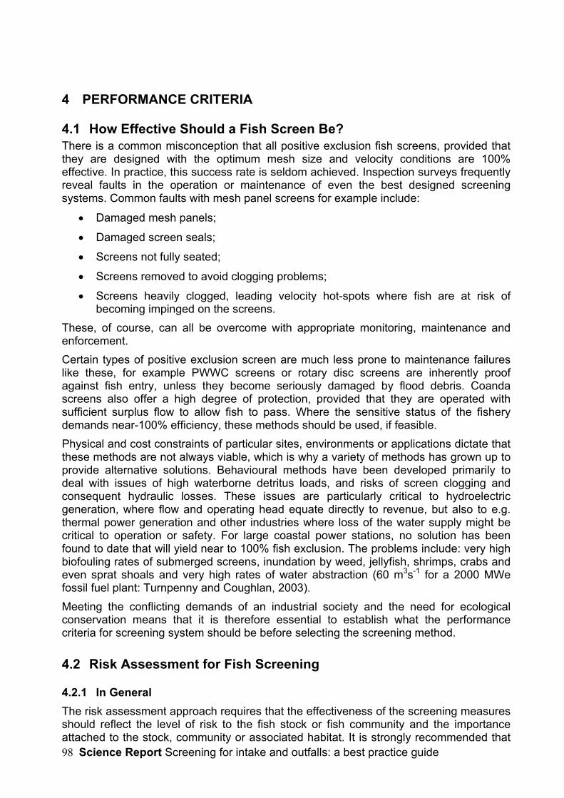
Science Report Screening for intake and outfalls: a best practice guide98
4 PERFORMANCE CRITERIA
4.1 How Effective Should a Fish Screen Be?There is a common misconception that all positive exclusion fish screens, provided thatthey are designed with the optimum mesh size and velocity conditions are 100%effective. In practice, this success rate is seldom achieved. Inspection surveys frequentlyreveal faults in the operation or maintenance of even the best designed screeningsystems. Common faults with mesh panel screens for example include:
• Damaged mesh panels;
• Damaged screen seals;
• Screens not fully seated;
• Screens removed to avoid clogging problems;
• Screens heavily clogged, leading velocity hot-spots where fish are at risk ofbecoming impinged on the screens.
These, of course, can all be overcome with appropriate monitoring, maintenance andenforcement.Certain types of positive exclusion screen are much less prone to maintenance failureslike these, for example PWWC screens or rotary disc screens are inherently proofagainst fish entry, unless they become seriously damaged by flood debris. Coandascreens also offer a high degree of protection, provided that they are operated withsufficient surplus flow to allow fish to pass. Where the sensitive status of the fisherydemands near-100% efficiency, these methods should be used, if feasible.Physical and cost constraints of particular sites, environments or applications dictate thatthese methods are not always viable, which is why a variety of methods has grown up toprovide alternative solutions. Behavioural methods have been developed primarily todeal with issues of high waterborne detritus loads, and risks of screen clogging andconsequent hydraulic losses. These issues are particularly critical to hydroelectricgeneration, where flow and operating head equate directly to revenue, but also to e.g.thermal power generation and other industries where loss of the water supply might becritical to operation or safety. For large coastal power stations, no solution has beenfound to date that will yield near to 100% fish exclusion. The problems include: very highbiofouling rates of submerged screens, inundation by weed, jellyfish, shrimps, crabs andeven sprat shoals and very high rates of water abstraction (60 m3s-1 for a 2000 MWefossil fuel plant: Turnpenny and Coughlan, 2003).Meeting the conflicting demands of an industrial society and the need for ecologicalconservation means that it is therefore essential to establish what the performancecriteria for screening system should be before selecting the screening method.
4.2 Risk Assessment for Fish Screening
4.2.1 In GeneralThe risk assessment approach requires that the effectiveness of the screening measuresshould reflect the level of risk to the fish stock or fish community and the importanceattached to the stock, community or associated habitat. It is strongly recommended that

Science Report Screening for intake and outfalls: a best practice guide 99
the principles of risk analysis are applied to any intake screening proposal. However, therequirements of the relevant legislation must be taken fully into account.Risk assessment in the fish screening context was addressed by Turnpenny et al.,(1998, 2000), who identified a number of factors that may be used in a risk assessmentof an abstraction scheme (hydroelectric schemes in their examples, but equallyapplicable to other types):
• the value of the fish stock in economic or conservation terms;
• the percentage of the fish stock that must pass the scheme;
• the percentage of those fish that pass successfully;
• the additional loss due to other schemes (i.e. cumulative impacts);
• the significance of given percentage levels of loss in economic and conservationterms.
These authors present simple mathematical approaches that could be extended todifferent applications. For example, they demonstrated that a behavioural barrier havinga 90% efficiency might achieve a successful scheme bypass rate of 98% when all factors(proportion of flow screened, etc.) are taken into account.
4.2.2 For Hydropower SitesSpecific consideration should be given to the following additional aspects at hydropowersites:
• the risk of fish injuries or mortalities in the turbines (via both intakes and outfalls);
• possible delays in fish migration and increased predation risk when water isdiverted through long head- and tailrace systems;
• possible losses at bywash outfalls where the increased concentration of divertedfish may attract predators, especially if fish are disorientated.
Issues associated with fish passage through turbines have been investigated in somedetail in studies funded by the Department of Trade and Industry (Turnpenny, 1998;Turnpenny et al., 1998, 2000). These authors conducted a series of laboratory and fieldexperiments, culminating in a computer model (‘STRIKER’) which predicts the probableinjury rates of fish of different sizes during passage through a hydroelectric turbine of theFrancis or Kaplan/propeller types. The model was validated on operating turbine sites. Ittakes account of injuries due to the following effects:
1. Runner strike- i.e. contact with the turbine blade;2. Contact with fixed elements (guide vanes etc.);3. Hydraulic shear stress (caused by hydraulic anomalies near the moving blades);4. Rapid pressure change (as the fish passes from the high-pressure to low-pressure
side of the blade).Turnpenny et al. (1998, 2000) describe how the model can be applied in fish riskassessment for a hydropower scheme.Methods of examining some of these factors on operating sites are discussed in section7.

Science Report Screening for intake and outfalls: a best practice guide100
4.2.3 For Water Transfer SchemesRisk assessment for procedures for screening at water transfer schemes, whether local(e.g. canal lock recharge pumping) or long-distance, should take account not only ofimpacts on fish communities in the source water body but also in the receiving water.This should include consideration of possible transfer of non-indigenous species aseggs, fry or other stages, spread of disease and interference with genetic integrity.
4.2.4 Under SFFA s.14Another approach is exemplified by the Environment Agency’s SFFA s. 14 riskassessment procedure. The Environment Agency is keen to demonstrate an effective buttransparent implementation of the SFFA s.14. The key elements of the EnvironmentAgency’s s.14 policy are:1. A standard risk assessment checklist procedure is used, the results of which are
made available to the responsible person/ owner and open to appeal.2. Full recognition is given to the precautionary approach (“where there are threats of
serious or irreversible damage, lack of full scientific certainty shall not be used as areason for postponing cost-effective measures to prevent environmentaldegradation”). This is complementary to the approach adopted in the HabitatsRegulations.
3. The Agency will ensure that adequate screening provisions are implemented but it isrecognised that the costs to industry should be in proportion to the magnitude of theperceived risk. At all times the principle of ‘best available technology not entailingexcessive cost’ (BATNEEC21) should be employed in options for screening.
4. Site inspections may only be carried out by enforcement staff who have receivedformal training in the new SFFA s.14 procedure. Such staff are required not to offeradvice on the design and construction of the suitable screening arrangements, whichare the responsibility of the responsible person or owner.
5. Figure 4.1 shows an example of the Agency’s SFFA s.14 checklist used as a basisfor the risk assessment.
21 Note that there is no formal definition of Best Available Technology (sensu Environment Act 1995) forfish screening at present
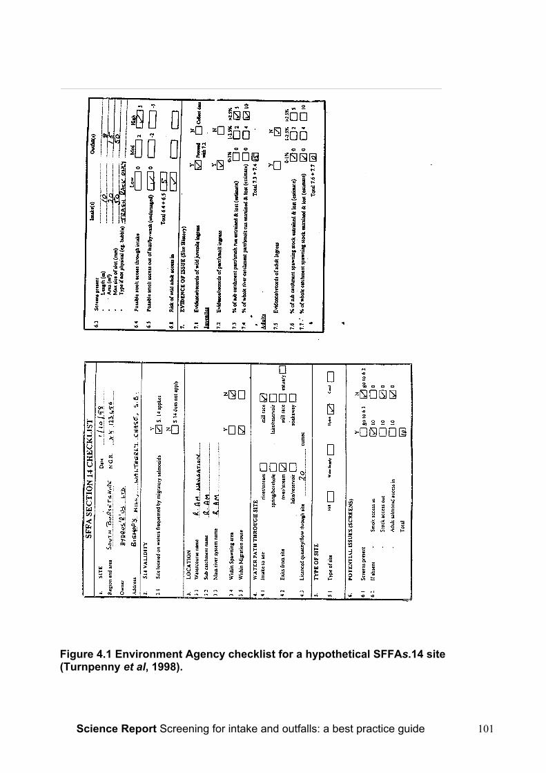
Science Report Screening for intake and outfalls: a best practice guide 101
Figure 4.1 Environment Agency checklist for a hypothetical SFFAs.14 site(Turnpenny et al, 1998).

Science Report Screening for intake and outfalls: a best practice guide102
4.2.5 Under the Habitats RegulationsProjects within or connected with a designated SAC and therefore regulated under theHabitats Regulations demand more stringent risk assessment criteria. The critical test iswhether the appropriate assessment can demonstrate no adverse effect on integrity ofthe European site. In this context, the BATNEEC criteria are replaced by BAT (BestAvailable Technology), without consideration to cost. The project may not proceed ifadverse effect on site integrity cannot be avoided. The appropriate assessment thereforeis the form of risk assessment procedure used in such cases.The Agency’s policy is summed in the following extracts from the website(www.environment-agency.gov.uk); note that the powers can apply to new and existingplans or projects that may be impacting upon SACs:“The Agency will ensure that all applications for new permissions will be screened forpotential impacts on European Sites. This applies to all proposals that require Agencyapproval and is a consolidation of existing statutory obligations to protect SSSIs underthe Wildlife and Countryside Act (1981), as amended by the Countryside and Rights ofWay Act (2000).Where a significant effect on a European site is likely, an appropriate assessment will becarried out by the Agency in consultation with EN22 and CCW23.In all cases the determination will be made by the Agency on best available informationand taking full account of advice from EN/CCW as agreed in this joint guidance.The Agency has obligations to review existing consents, licences, permissions andactivities that are likely to be having a significant effect on a European Site. Thisassessment of likely significant effect is in relation to the permission alone or incombination with other permissions or plans or projects. Where a likely significant effectis established, the Agency will carry out an appropriate assessment to determinewhether to affirm, modify or revoke the permission.Under the Review of Consents process, an appropriate assessment will be undertakenfor those European sites protected in the UK by means of Regulation 10 (1) of theConservation (Natural Habitats, & c.) Regulations 1994 as amended by the Conservation(Natural Habitats, & c) (Amendment) (England) Regulations 2000.The process will affect only those permissions that have been identified as ‘relevant’using guidance agreed with EN and CCW, and by those with the legal powers to do so”.The process is well illustrated by the case of Fawley Power Station in Hampshire, an oil-fired plant that has been in operation since the late 1960s. Following the designation ofcandidate SACs on the Solent (marine habitat) and R. Itchen (salmon river), lying to thesouth and north respectively of the plant, a new abstraction licence was issued in theyear 2002. As a result of an assessment under the Habitat Regulations, to remove therisk of an adverse effect on site integrity, various conditions were attached to the licence,including:
• the installation and operation of an acoustic fish deterrent system at the coolingwater intake;
22 English Nature23 Countryside Council for Wales

Science Report Screening for intake and outfalls: a best practice guide 103
• implementation of a fish rescue and return facility at the cooling water drumscreens;
• operation of a weekly/monthly fish catch monitoring programme on the coolingwater drum screens to estimate total annual fish catch for an indefinite period;
• quarterly sampling of fish by several capture methods at designated referencesites in Southampton water and the Solent, against which to judge any changein fish catch at the plant;
• annual reporting of the findings to the Agency.
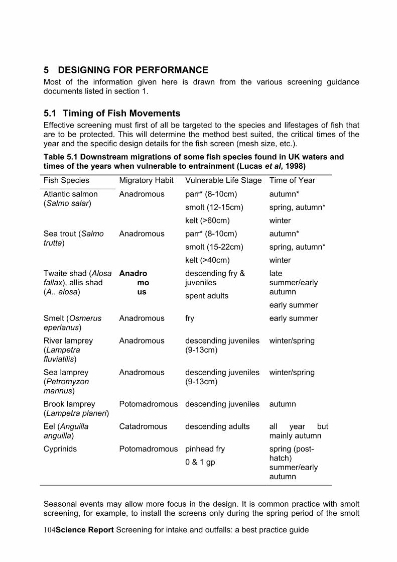
Science Report Screening for intake and outfalls: a best practice guide104
5 DESIGNING FOR PERFORMANCEMost of the information given here is drawn from the various screening guidancedocuments listed in section 1.
5.1 Timing of Fish MovementsEffective screening must first of all be targeted to the species and lifestages of fish thatare to be protected. This will determine the method best suited, the critical times of theyear and the specific design details for the fish screen (mesh size, etc.).Table 5.1 Downstream migrations of some fish species found in UK waters andtimes of the years when vulnerable to entrainment (Lucas et al, 1998)Fish Species Migratory Habit Vulnerable Life Stage Time of Year
Atlantic salmon(Salmo salar)
Anadromous parr* (8-10cm)smolt (12-15cm)kelt (>60cm)
autumn*spring, autumn*winter
Sea trout (Salmotrutta)
Anadromous parr* (8-10cm)smolt (15-22cm)kelt (>40cm)
autumn*spring, autumn*winter
Twaite shad (Alosafallax), allis shad(A.. alosa)
Anadromous
descending fry &juvenilesspent adults
latesummer/earlyautumnearly summer
Smelt (Osmeruseperlanus)
Anadromous fry early summer
River lamprey(Lampetrafluviatilis)
Anadromous descending juveniles(9-13cm)
winter/spring
Sea lamprey(Petromyzonmarinus)
Anadromous descending juveniles(9-13cm)
winter/spring
Brook lamprey(Lampetra planeri)
Potomadromous descending juveniles autumn
Eel (Anguillaanguilla)
Catadromous descending adults all year butmainly autumn
Cyprinids Potomadromous pinhead fry0 & 1 gp
spring (post-hatch)summer/earlyautumn
Seasonal events may allow more focus in the design. It is common practice with smoltscreening, for example, to install the screens only during the spring period of the smolt
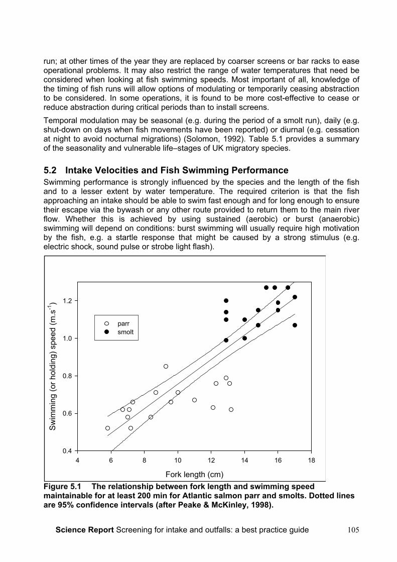
Science Report Screening for intake and outfalls: a best practice guide 105
run; at other times of the year they are replaced by coarser screens or bar racks to easeoperational problems. It may also restrict the range of water temperatures that need beconsidered when looking at fish swimming speeds. Most important of all, knowledge ofthe timing of fish runs will allow options of modulating or temporarily ceasing abstractionto be considered. In some operations, it is found to be more cost-effective to cease orreduce abstraction during critical periods than to install screens.Temporal modulation may be seasonal (e.g. during the period of a smolt run), daily (e.g.shut-down on days when fish movements have been reported) or diurnal (e.g. cessationat night to avoid nocturnal migrations) (Solomon, 1992). Table 5.1 provides a summaryof the seasonality and vulnerable life–stages of UK migratory species.
5.2 Intake Velocities and Fish Swimming PerformanceSwimming performance is strongly influenced by the species and the length of the fishand to a lesser extent by water temperature. The required criterion is that the fishapproaching an intake should be able to swim fast enough and for long enough to ensuretheir escape via the bywash or any other route provided to return them to the main riverflow. Whether this is achieved by using sustained (aerobic) or burst (anaerobic)swimming will depend on conditions: burst swimming will usually require high motivationby the fish, e.g. a startle response that might be caused by a strong stimulus (e.g.electric shock, sound pulse or strobe light flash).
Figure 5.1 The relationship between fork length and swimming speedmaintainable for at least 200 min for Atlantic salmon parr and smolts. Dotted linesare 95% confidence intervals (after Peake & McKinley, 1998).
Fork length (cm)
4 6 8 10 12 14 16 18
Swim
min
g (o
r hol
ding
) spe
ed (m
.s-1
)
0.4
0.6
0.8
1.0
1.2
parrsmolt
Science Report Screening for intake and outfalls: a best practice guide106
5.2.1 Salmonid SmoltsFor salmonid smolts, a swimming speed equivalent to 2 body-lengths per second (bl s-1)has for a long time been taken as the 'design' value for water intakes (Solomon, 1992).While the 2 bl.s-1 criterion has been widely used, it is based at least in part upon thenotion that the process of smoltification causes some physiological impairment ofswimming ability. Solomon (1992) refers to data from Thorpe & Morgan (1978) whichindicated that a 12 cm parr could maintain station in current speeds of up to 7 bl.s-1,whereas hatchery-reared smolts were unable to maintain station at >2 bl.s-1. In fact, theirpaper refers to position-holding in non-swimming smolt, not smolts in the water column.More recent studies with actively migrating wild Atlantic salmon smolts showed thatsmolts performed at least as well as parr (Peake & McKinley, 1998; see Figure 5.1) andbetter than some other salmonids (Peake et al., 1997). Data from Peake & McKinley(1998) indicate that e.g. an average 12 cm smolt could sustain a swimming speed of7.1 bl.s-1 (85 cms-1) indefinitely. Following the Agency’s recommendations from the fishswimming speed R & D24 that the 90th%ile value should be used (i.e. the swimmingspeed attainable by 90% of the population), when using swimming speeds in fisheriesengineering designs, it would be safer to work with a lower-than-average value, e.g.75 cms-1 (equating to the average for a 10 cm parr or smolt); this value is equivalent tothe 90%ile value for parr or smolts in the size range 10-15cm. The Peake & McKinleytests were carried out at temperatures of between 12-20oC; while water temperaturepotentially may influence fish swimming performance, the effect of temperature acrossthis range was not statistically discernible within their dataset. At very low temperatures(i.e. below 5oC) it might be expected that swimming would be cold-impaired but smoltmigrations do not commonly occur at such low temperatures. Swimming trials of browntout conducted under R & D Project W2-02625 concluded that performance was generallybetter at temperatures between 5-12oC than at higher temperatures, and the same maybe true for salmon and sea trout, both of which are cold-water species. Therefore the 75cms-1 value can be considered a speed that would be sustainable by smolts of eitherspecies at sizes and temperatures commonly found in British waters.
5.2.2 Salmonid KeltMeasurements by Booth et al. (in Turnpenny et al., 1998) show maximum sustainableswimming speed of 2 bl.s-1 for Atlantic salmon kelt at a water temperature of 7oC.
5.2.3 Other Freshwater Fish SpeciesR & D Project No. W2-049 “Swimming Speeds in Fish” investigated the swimmingspeeds of various freshwater fish species, including: brown trout, barbel (Barbus barbus),grayling (Thymallus thymallus), eel, bream, roach, chub (Leuciscus cephalus), dace(Leuciscus leuciscus) smelt, and adult shad. Data are available for a range of fish sizes(but not fry, at present) and water temperatures. A computer program “SWIMIT (v2.1)”allows swimming speeds to be calculated for each of these species according to bodylength and temperature. Table 5.1 presents data extracted from SWIMIT (v2.1) for arange of fish sizes and water temperatures. It is recommended that 90th percentile valuesfor endurance (not burst) speed should be used to determine design values for intakeescape velocity. It is prudent when doing so to allow for the smallest size group of fishlikely to be present and the lowest water temperature band. Note that shad have not 24 Environment Agency National R & D Project W2-026, “Swimming Speed in Fish”
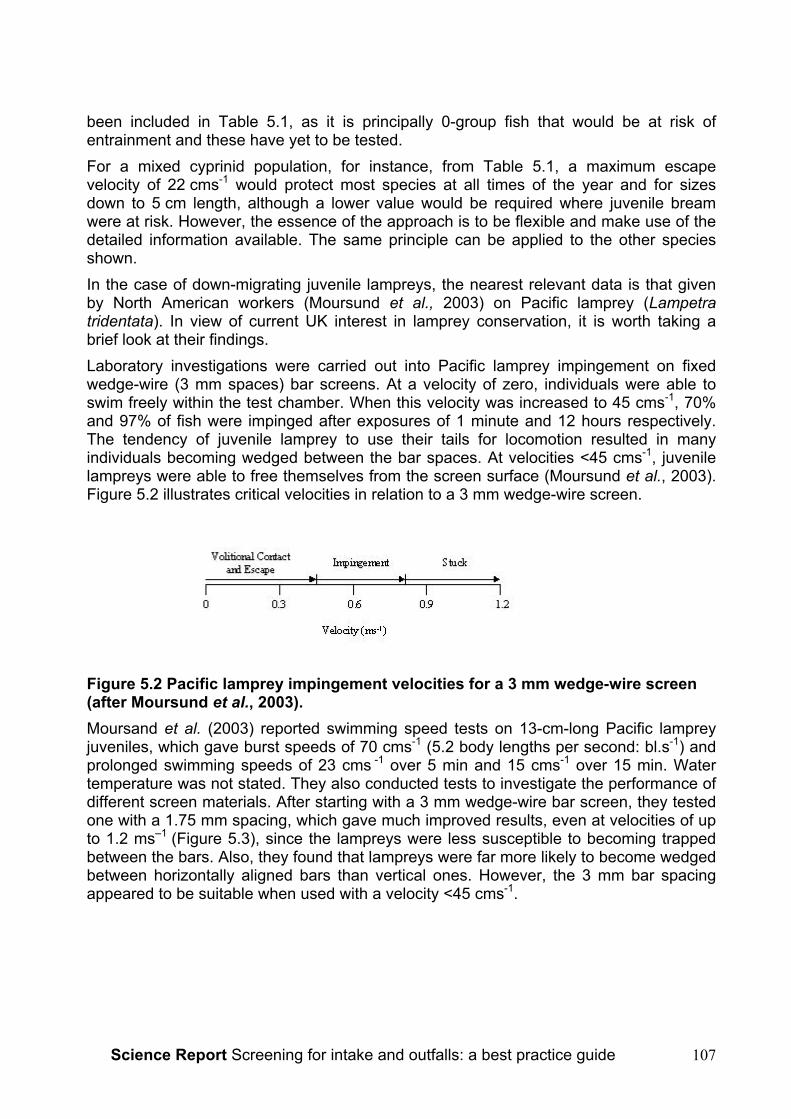
Science Report Screening for intake and outfalls: a best practice guide 107
been included in Table 5.1, as it is principally 0-group fish that would be at risk ofentrainment and these have yet to be tested.For a mixed cyprinid population, for instance, from Table 5.1, a maximum escapevelocity of 22 cms-1 would protect most species at all times of the year and for sizesdown to 5 cm length, although a lower value would be required where juvenile breamwere at risk. However, the essence of the approach is to be flexible and make use of thedetailed information available. The same principle can be applied to the other speciesshown.In the case of down-migrating juvenile lampreys, the nearest relevant data is that givenby North American workers (Moursund et al., 2003) on Pacific lamprey (Lampetratridentata). In view of current UK interest in lamprey conservation, it is worth taking abrief look at their findings.Laboratory investigations were carried out into Pacific lamprey impingement on fixedwedge-wire (3 mm spaces) bar screens. At a velocity of zero, individuals were able toswim freely within the test chamber. When this velocity was increased to 45 cms-1, 70%and 97% of fish were impinged after exposures of 1 minute and 12 hours respectively.The tendency of juvenile lamprey to use their tails for locomotion resulted in manyindividuals becoming wedged between the bar spaces. At velocities <45 cms-1, juvenilelampreys were able to free themselves from the screen surface (Moursund et al., 2003).Figure 5.2 illustrates critical velocities in relation to a 3 mm wedge-wire screen.
Figure 5.2 Pacific lamprey impingement velocities for a 3 mm wedge-wire screen(after Moursund et al., 2003).Moursand et al. (2003) reported swimming speed tests on 13-cm-long Pacific lampreyjuveniles, which gave burst speeds of 70 cms-1 (5.2 body lengths per second: bl.s-1) andprolonged swimming speeds of 23 cms -1 over 5 min and 15 cms-1 over 15 min. Watertemperature was not stated. They also conducted tests to investigate the performance ofdifferent screen materials. After starting with a 3 mm wedge-wire bar screen, they testedone with a 1.75 mm spacing, which gave much improved results, even at velocities of upto 1.2 ms–1 (Figure 5.3), since the lampreys were less susceptible to becoming trappedbetween the bars. Also, they found that lampreys were far more likely to become wedgedbetween horizontally aligned bars than vertical ones. However, the 3 mm bar spacingappeared to be suitable when used with a velocity <45 cms-1.
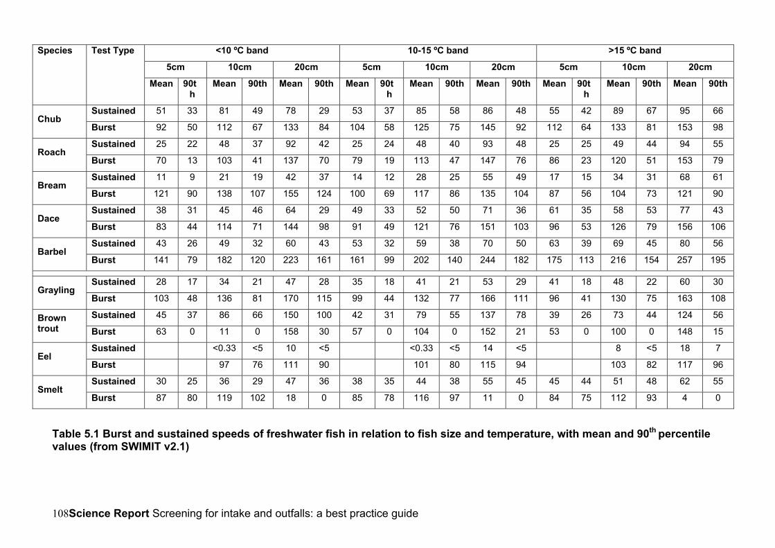
Science Report Screening for intake and outfalls: a best practice guide108
<10 ºC band 10-15 ºC band >15 ºC band
5cm 10cm 20cm 5cm 10cm 20cm 5cm 10cm 20cm
Species Test Type
Mean 90th
Mean 90th Mean 90th Mean 90th
Mean 90th Mean 90th Mean 90th
Mean 90th Mean 90th
Sustained 51 33 81 49 78 29 53 37 85 58 86 48 55 42 89 67 95 66Chub
Burst 92 50 112 67 133 84 104 58 125 75 145 92 112 64 133 81 153 98
Sustained 25 22 48 37 92 42 25 24 48 40 93 48 25 25 49 44 94 55Roach
Burst 70 13 103 41 137 70 79 19 113 47 147 76 86 23 120 51 153 79
Sustained 11 9 21 19 42 37 14 12 28 25 55 49 17 15 34 31 68 61Bream
Burst 121 90 138 107 155 124 100 69 117 86 135 104 87 56 104 73 121 90
Sustained 38 31 45 46 64 29 49 33 52 50 71 36 61 35 58 53 77 43Dace
Burst 83 44 114 71 144 98 91 49 121 76 151 103 96 53 126 79 156 106
Sustained 43 26 49 32 60 43 53 32 59 38 70 50 63 39 69 45 80 56Barbel
Burst 141 79 182 120 223 161 161 99 202 140 244 182 175 113 216 154 257 195
Sustained 28 17 34 21 47 28 35 18 41 21 53 29 41 18 48 22 60 30Grayling
Burst 103 48 136 81 170 115 99 44 132 77 166 111 96 41 130 75 163 108
Sustained 45 37 86 66 150 100 42 31 79 55 137 78 39 26 73 44 124 56Browntrout Burst 63 0 11 0 158 30 57 0 104 0 152 21 53 0 100 0 148 15
Sustained <0.33 <5 10 <5 <0.33 <5 14 <5 8 <5 18 7Eel
Burst 97 76 111 90 101 80 115 94 103 82 117 96
Sustained 30 25 36 29 47 36 38 35 44 38 55 45 45 44 51 48 62 55Smelt
Burst 87 80 119 102 18 0 85 78 116 97 11 0 84 75 112 93 4 0
Table 5.1 Burst and sustained speeds of freshwater fish in relation to fish size and temperature, with mean and 90th percentilevalues (from SWIMIT v2.1)
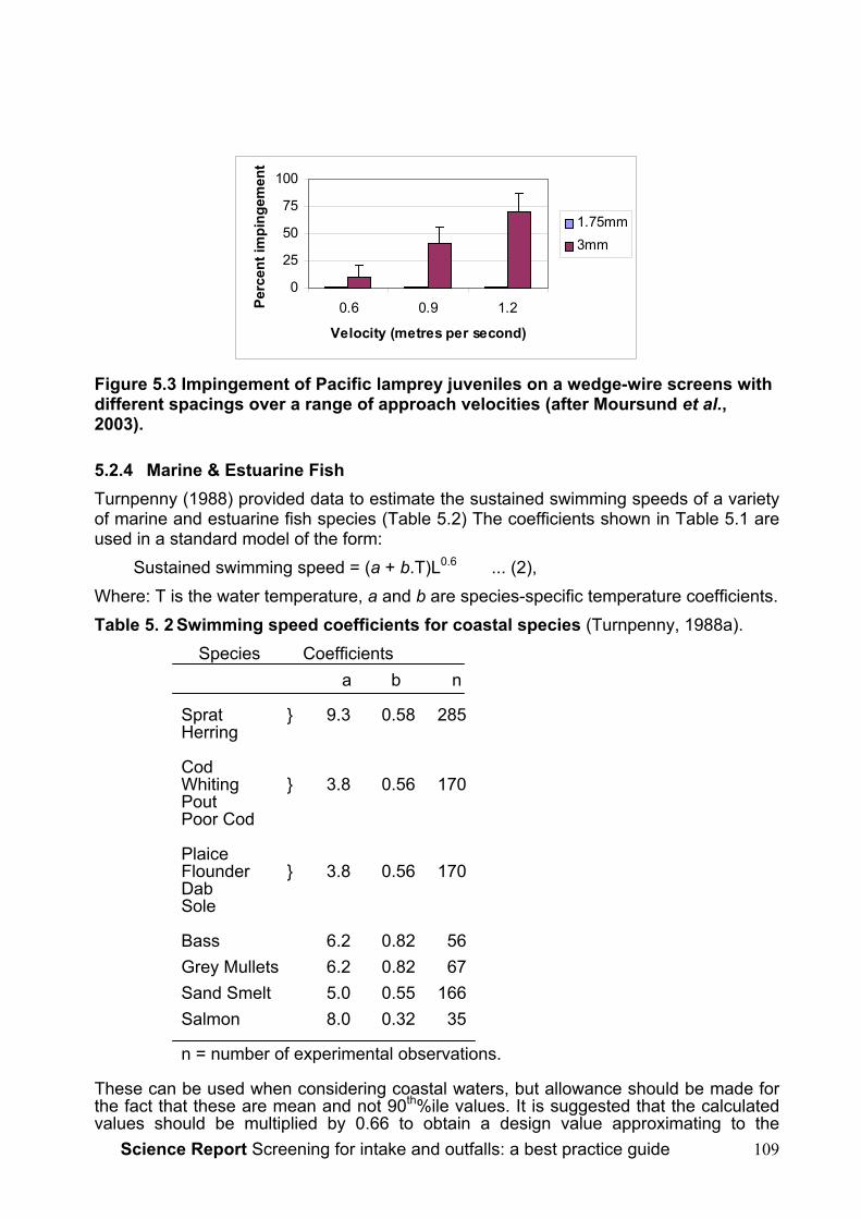
Science Report Screening for intake and outfalls: a best practice guide 109
0
25
50
75
100
0.6 0.9 1.2
Velocity (metres per second)
Perc
ent i
mpi
ngem
ent
1.75mm3mm
Figure 5.3 Impingement of Pacific lamprey juveniles on a wedge-wire screens withdifferent spacings over a range of approach velocities (after Moursund et al.,2003).
5.2.4 Marine & Estuarine FishTurnpenny (1988) provided data to estimate the sustained swimming speeds of a varietyof marine and estuarine fish species (Table 5.2) The coefficients shown in Table 5.1 areused in a standard model of the form:
Sustained swimming speed = (a + b.T)L0.6 ... (2),Where: T is the water temperature, a and b are species-specific temperature coefficients.Table 5. 2 Swimming speed coefficients for coastal species (Turnpenny, 1988a).
Species Coefficientsa b n
Sprat } 9.3 0.58 285Herring
CodWhiting } 3.8 0.56 170PoutPoor Cod
PlaiceFlounder } 3.8 0.56 170DabSole
Bass 6.2 0.82 56Grey Mullets 6.2 0.82 67Sand Smelt 5.0 0.55 166Salmon 8.0 0.32 35
n = number of experimental observations.
These can be used when considering coastal waters, but allowance should be made forthe fact that these are mean and not 90th%ile values. It is suggested that the calculatedvalues should be multiplied by 0.66 to obtain a design value approximating to the
Science Report Screening for intake and outfalls: a best practice guide110
90th%ile: this is typically the difference found between mean and 90th percentile values inR & D Project No. W2-049 (Table 5.1)
5.2.5 Channel Velocities and Approach/Escape VelocitiesThere is some confusion over the terminology used by different authors and the followingdefinitions are proposed (see Figure 5.5):
1. the channel velocity is the velocity in front of the screen measured axial to theflow channel;
2. the escape velocity is the velocity in front of the screen measured perpendicularto the screen face, irrespective of the screen angle to flow - i.e. it is theminimum velocity at which a fish would need to swim in order to escape. This isalso known by some authors as the ‘approach velocity’; by convention, this ismeasured a short distance (e.g. 10 cm) in front of the screen, where a fishmight swim, rather than for example between the bars of the screen (Nordland,1996; Turnpenny et al., 1998).
The screen should be designed to give a maximum escape velocity that is within theswimming performance capabilities of the fish that are to be excluded by the screen (seeabove). In selecting an appropriate value, allowance should be made for:
• partial clogging of the screen (depending on the level of debris present and theexpected efficiency of any screen cleaning mechanism);
• any silt build-up in front of the screen that is likely to occur between routine de-siltingoperations.
It is recommended that screens should be designed with at least 20% over-capacity toallow for partial blockage or blinding.
5.2.6 Advisory Escape Velocities for Fish ScreensNo statutory limits on escape velocities exist at present within the UK and the onus onthe operator is to provide a system that avoids injury to fish (Turnpenny et al., 1998). TheSalmon Advisory Committee (1995) recommended an escape velocity of 25 cms-1, whileThe Scottish Office (Anon., 1995) suggest 2 body-lengths per second (bl s-1), whichmight equate to 25 cms-1 for a typical Scottish smolt size of 12.5 cm, or 30 cms-1 for a 15cm smolt that might be found further south. Solomon (1992), suggested an escapevelocity of 30 cms-1 would be appropriate for smolt, while a lower velocity of 15 cms-1
would be required where coarse fish were present.In the light of the published scientific data presented in section 5.2, these values appeartoo restrictive for many situations and would potentially impose unnecessary constructionand maintenance costs on developers and operators of intakes. Where goodexperimental data exist to develop more informed design criteria, their use isrecommended. For most cases it will be appropriate to use the 90th percentile maximumsustainable swimming speed (MSSS), based on the smallest size of fish and the lowestwater temperature that the species is likely to encounter at the facility. This value impliesthat 90% of the fish approaching the screening system would be capable of maintainingthat speed for up to 200 min. In a well-designed screening system, which offersadequate guidance cues to steer fish towards the bywash entrance, this period should bemore than adequate for fish to pass the screen.

Science Report Screening for intake and outfalls: a best practice guide 111
For most purposes, the swimming speed R & D (W2-026) (see Table 5.1) indicates thatthe following criteria would be suitable (Table 5.3):Table 5.3 Maximum recommended escape velocities for intake where salmonids orcyprinids are presentFish Present Maximum Escape Velocity
Perpendicular to the Screen
Salmonids ≥10cm in length, includingkelt
75 cms-1
Cyprinids (except bream) ≥ 5cm inlength
22 cms-1
Aitken et al. (1966) refer to design limits of 0.75-0.90 ms-1 for kelt. Based on theswimming speed information given above, which indicates a sustainable speed of 2 bls-1
for kelt, the 75 cms-1 value for smolts would be a suitable design limit for all Atlanticsalmon applications, although smaller sea trout kelt would require a proportionately lowerlimit.For fish of different sizes or other species, these values would need to be revisedaccording to available experimental data.Experimental data are not yet available for juvenile shad, nor for European lampreyspecies. Where 3 mm wedge-wire screening material is used, the 45 cms-1 ‘volitionalescape’ value given by Moursand et al. (2002) for Pacific lampreys may be appropriate,but it is recommended that a more conservative design value of 30 cms-1 should beadopted until robust experimental data for European species become available. Forjuvenile shad, sprat/herring data from Table 5.2 should provide a reasonableapproximation.
5.2.7 Uniformity of Flow ConditionsIn calculating escape velocities, the most common approach used by engineers is to takethe average velocity (U), as given by the flow (Q) divided by the total screen area (A):
=
AQU (1).
This provides an initial indication but does not take account of bed and wall friction,which will tend to reduce velocities near to surfaces, leading to higher values in the mid-and upper-channel, nor does it allow for any flow asymmetry caused by inertial effects onbends or angles. Hydraulic modelling can provide useful insights into these aspects andallow an intake design to be developed or modified to achieve the desired flows at thescreen surface.Should the velocity at the screen face always be uniform? Generally it should. The chiefpurpose in hydraulic design is to avoid high velocity 'hot-spots' that might cause fish tobe impinged onto the screen, resulting in possible death or injury (see below).Attention is also drawn to asymmetrical changes to the flow distribution that can becaused by sedimentation. Ideally, this possibility would be anticipated through theapplication of hydraulic studies to predict the sedimentation regime.

Science Report Screening for intake and outfalls: a best practice guide112
5.3 Fish Behaviour in Front of ScreensA screen or trash rack represents an obstacle in the flow-path and fish approaching thescreen generally turn to face upstream upon meeting it. However, their behaviour in frontof the screen depends on the velocity conditions. This effect has been described byvarious authors (Rainey, 1985; Pavlov, 1989; Turnpenny et al., 1998).
• At low escape velocities relative to their swimming capacity (e.g. @<2 bls-1), aschool of fish approaching a screen are often seen to circle around upstream of it,searching for an escape route. The leading fish may then locate the bywash entranceand enter it, head first, some or all of the other fish in the school then following it. Ifthe hydraulic or other conditions in the bywash are unsuitable, and the channelvelocity is low, the fish may elect to swim back upstream to find another route. Theauthor (AWHT) has observed smolts migrating back up a lade over a distance of500 m to re-enter the main river when the bywash was unsuitable.
• At intermediate escape velocities, close to their maximum sustainable speed, fishwill face upstream into the flow and pass tail-first into the bywash (see Figure 5.4,lower diagram).
• At high escape velocities, above their maximum sustainable speed, fish willorientate perpendicular to the screen face and pass tail-first into the bywash. Thisorientation allows the fish to avoid impingement on the screen using the lowestpossible swimming speed and is therefore the limiting case for screen design.
Figure 5.4 Fish movement in front of angled screens and louvres. Lower diagramapplies when the channel velocity is below or near the maximum sustainableswimming speed of the fish, upper diagram when channel velocity exceeds theswimming speed of the fish (Rainey, 1985).
5.4 Effect of Screen Angle to FlowBy placing the screen or trash rack at a diagonal angle to the flow (as seen in plan view),fish can be guided to the lower end of the diagonal where a bywash is provided to permittheir safe transit downstream. Figure 5.4 again illustrates this principle. Furthermore, theangle of the screen can be set to ensure that the escape velocity is kept below requireddesign value. A screen or trash rack set at a diagonal angle to the flow to bias the fish
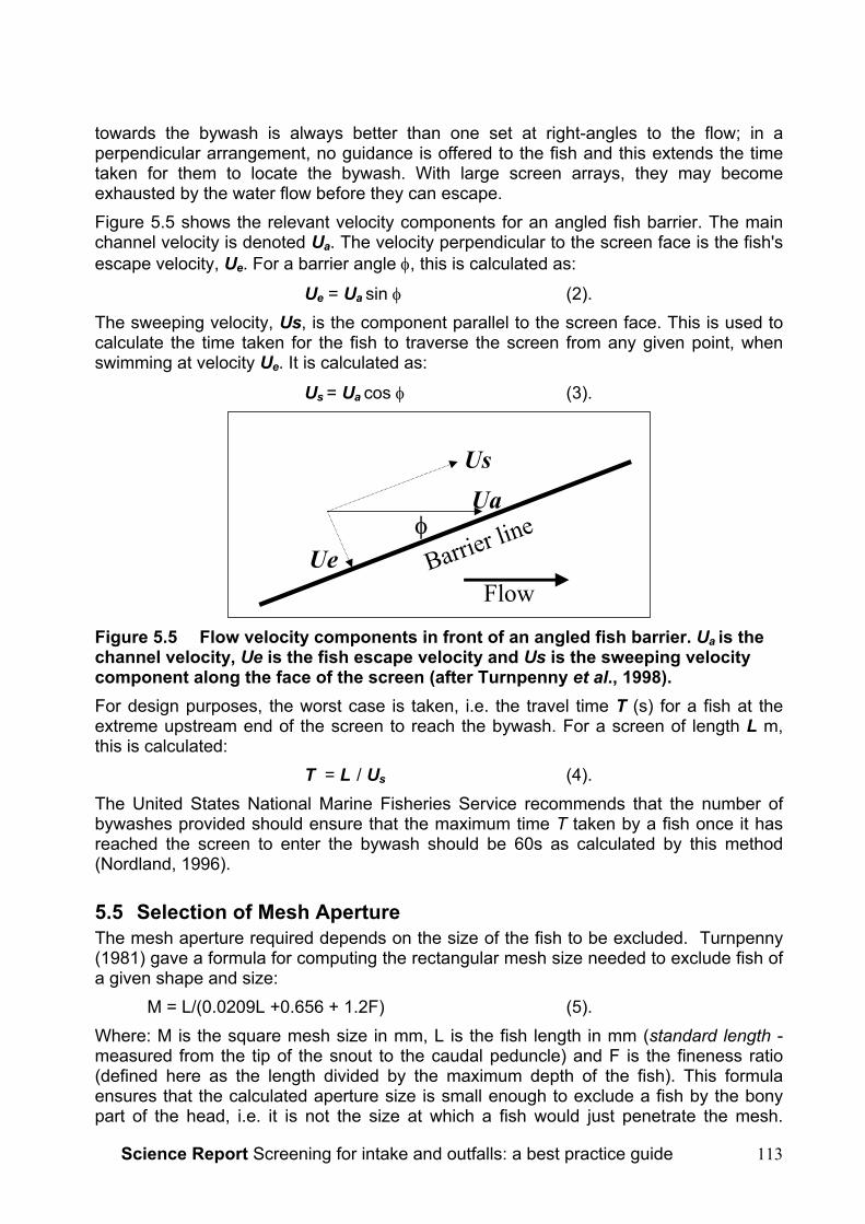
Science Report Screening for intake and outfalls: a best practice guide 113
towards the bywash is always better than one set at right-angles to the flow; in aperpendicular arrangement, no guidance is offered to the fish and this extends the timetaken for them to locate the bywash. With large screen arrays, they may becomeexhausted by the water flow before they can escape.Figure 5.5 shows the relevant velocity components for an angled fish barrier. The mainchannel velocity is denoted Ua. The velocity perpendicular to the screen face is the fish'sescape velocity, Ue. For a barrier angle φ, this is calculated as:
Ue = Ua sin φ (2).The sweeping velocity, Us, is the component parallel to the screen face. This is used tocalculate the time taken for the fish to traverse the screen from any given point, whenswimming at velocity Ue. It is calculated as:
Us = Ua cos φ (3).
φ
UsUa
Ue Barrier line
Flow
Figure 5.5 Flow velocity components in front of an angled fish barrier. Ua is thechannel velocity, Ue is the fish escape velocity and Us is the sweeping velocitycomponent along the face of the screen (after Turnpenny et al., 1998).For design purposes, the worst case is taken, i.e. the travel time T (s) for a fish at theextreme upstream end of the screen to reach the bywash. For a screen of length L m,this is calculated:
T = L / Us (4).The United States National Marine Fisheries Service recommends that the number ofbywashes provided should ensure that the maximum time T taken by a fish once it hasreached the screen to enter the bywash should be 60s as calculated by this method(Nordland, 1996).
5.5 Selection of Mesh ApertureThe mesh aperture required depends on the size of the fish to be excluded. Turnpenny(1981) gave a formula for computing the rectangular mesh size needed to exclude fish ofa given shape and size:
M = L/(0.0209L +0.656 + 1.2F) (5).Where: M is the square mesh size in mm, L is the fish length in mm (standard length -measured from the tip of the snout to the caudal peduncle) and F is the fineness ratio(defined here as the length divided by the maximum depth of the fish). This formulaensures that the calculated aperture size is small enough to exclude a fish by the bonypart of the head, i.e. it is not the size at which a fish would just penetrate the mesh.
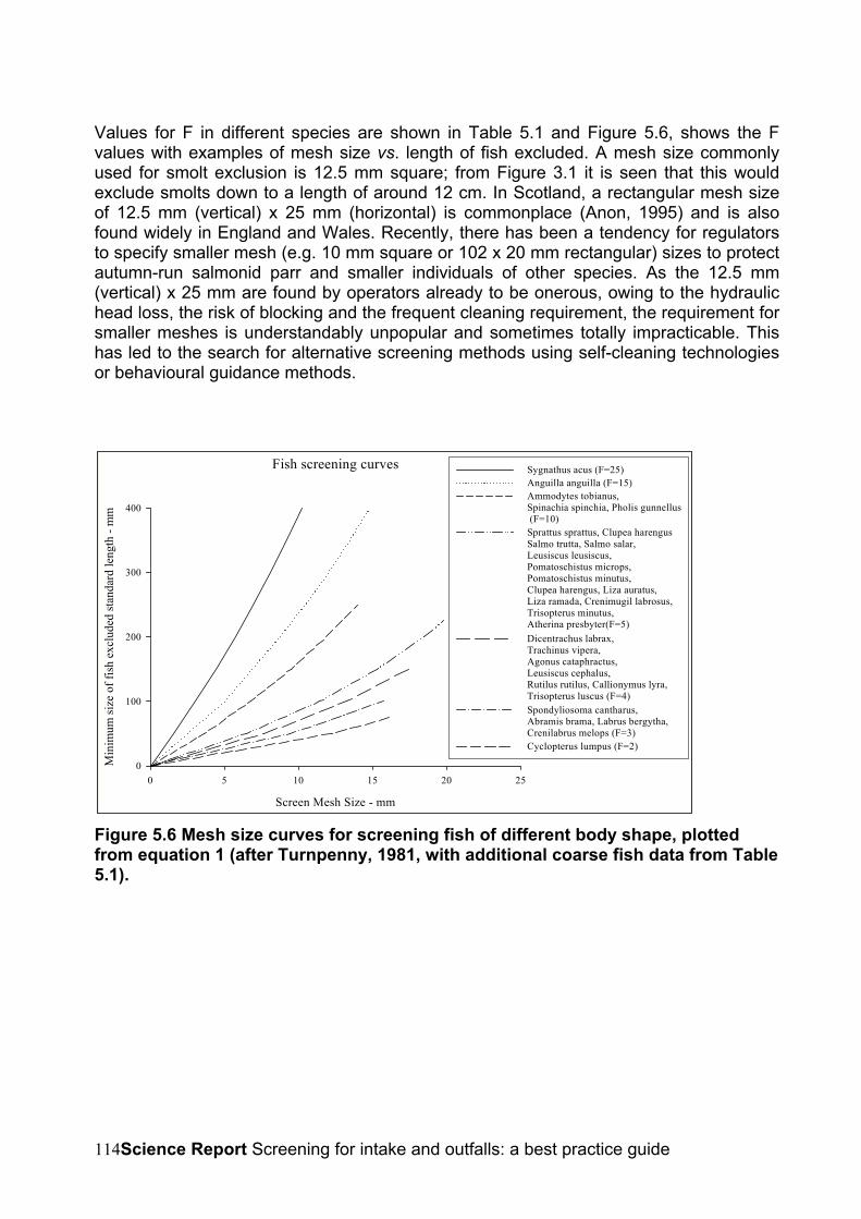
Science Report Screening for intake and outfalls: a best practice guide114
Values for F in different species are shown in Table 5.1 and Figure 5.6, shows the Fvalues with examples of mesh size vs. length of fish excluded. A mesh size commonlyused for smolt exclusion is 12.5 mm square; from Figure 3.1 it is seen that this wouldexclude smolts down to a length of around 12 cm. In Scotland, a rectangular mesh sizeof 12.5 mm (vertical) x 25 mm (horizontal) is commonplace (Anon, 1995) and is alsofound widely in England and Wales. Recently, there has been a tendency for regulatorsto specify smaller mesh (e.g. 10 mm square or 102 x 20 mm rectangular) sizes to protectautumn-run salmonid parr and smaller individuals of other species. As the 12.5 mm(vertical) x 25 mm are found by operators already to be onerous, owing to the hydraulichead loss, the risk of blocking and the frequent cleaning requirement, the requirement forsmaller meshes is understandably unpopular and sometimes totally impracticable. Thishas led to the search for alternative screening methods using self-cleaning technologiesor behavioural guidance methods.
Fish screening curves
Screen Mesh Size - mm
0 5 10 15 20 25
Min
imum
size
of f
ish
excl
uded
stan
dard
leng
th -
mm
0
100
200
300
400
Sygnathus acus (F=25)Anguilla anguilla (F=15)Ammodytes tobianus, Spinachia spinchia, Pholis gunnellus (F=10)Sprattus sprattus, Clupea harengusSalmo trutta, Salmo salar, Leusiscus leusiscus, Pomatoschistus microps,Pomatoschistus minutus,Clupea harengus, Liza auratus,Liza ramada, Crenimugil labrosus,Trisopterus minutus,Atherina presbyter(F=5)Dicentrachus labrax,Trachinus vipera, Agonus cataphractus,Leusiscus cephalus, Rutilus rutilus, Callionymus lyra,Trisopterus luscus (F=4)Spondyliosoma cantharus, Abramis brama, Labrus bergytha,Crenilabrus melops (F=3)Cyclopterus lumpus (F=2)
Figure 5.6 Mesh size curves for screening fish of different body shape, plottedfrom equation 1 (after Turnpenny, 1981, with additional coarse fish data from Table5.1).

Science Report Screening for intake and outfalls: a best practice guide 115
Table 5.1 Observed fineness ratios for 24 marine and freshwater fish species(Turnpenny, 1981, with additional data for cyprinids)
Species Scientific Name Fineness Ratio (F)Bass Dicentrachus labrax 3.67Bream Abramis brama 2.99Butterfish Pholis gunnellus 7.73Chub Leusiscus cephalus 4.39Dace Leusiscus leusiscus 4.83Dragonet Callionymus lyra 4.28Eel Anguilla anguilla 16Goby (Common) Pomatoschistus microps 5.7Goby (Sand) Pomatoschistus minutus 5.7Herring Clupea harengus 4.75Hooknose Agonus cataphractus 3.87Lumpsucker Cyclopterus lumpus 2.07Mullet (Golden) Liza auratus 4.67Mullet (Thick Lip) Crenimugil labrosus 4.67Mullet (Thin Lip) Liza ramada 4.67Pipefish (Greater) Sygnathus acus 25.2Poor Cod Trispoterus minutus 4.58Pout Trispoterus luscus 3.92Roach Rutilus rutilus 3.51Salmon Salmo salar 4.65Sand eel Ammodytes tobianus 10.2Sand smelt Atherina presbyter 5.29Sea Bream (Black) Spondyliosoma cantharus 2.88Sprat Sprattus sprattus 4.75Stickleback (15 spine) Spinachia spinachia 10.9Trout Salmo trutta 4.37Weever (Lesser) Trachinus vipera 3.68Wrasse (Ballan) Labrus bergylta 3.06Wrasse (Corkwing) Crenilabrus melops 3.06
5.6 Screening for Epibenthic SpeciesFor species that normally live close to the bed, the simple precaution of raising the invertor threshold of any horizontal intake opening may help in reducing entrainment. In arecent survey carried out to determine the optimum opening level for an intake in anestuarine location, different trawling gears were used to compare catch rates just belowthe water surface and at bed level (A.W.H.Turnpenny, Babtie Aquatic, unpublished data). This was intended to simulate abstraction from a floating pontoon-mounted intakeversus a fixed bed-level intake. Predicted fish entrainment levels were reduced by 50%for the floating intake compared with the bed-mounted option. The composition of thecatch shifted from one dominated by flatfish and gobies to principally pelagic species.This concept is also valid for freshwater intakes to reduce the risk to species such asbullheads and loaches. Heuer and Tomljanovich (1979), investigating factors affectingimpingement of fish on vertical screens found that provision of a bottom refuge made byblanking off the lower 9 cm of the screen significantly reduced the risk to species livingnear to the bed.
Science Report Screening for intake and outfalls: a best practice guide116
5.7 Bywash Design CriteriaThe placement of a screen flush at the entrance to a channel avoids the need for abywash, but a sweeping flow is then required to carry fish downstream. Spillway screens(Coanda-effect, Smoltsafe) require no dedicated bywash structure as such, but dorequire a surplus flow to convey fish downstream. The bywash must be regarded asintegral part of the screening system. A good bywash requires thoughtful design andverification of performance.
5.7.1 Bywash LocationLocation of the bywash entrance is important. The entrance to a bywash should bepositioned so as to maximise the chances of fish locating it. For an angled screenarrangement, it should be located at the downstream end, in the cleft formed by thescreen and the bank or channel wall (see Figure 5.4). The opening should be no morethan a metre or two upstream of the screen face. For very large screen arrays, there is arisk that fish may become exhausted or disorientated before fully traversing the screen,in which case, additional bywash entrances would need to be provided at intervals alongthe screen face. It is unlikely that this would be necessary for screen arrays less than ahundred metres in length, provided that the escape velocity was kept within thesustainable swimming speed limits of the fish, and that there were no structures such aspiers getting in the way. At hydropower plants, the bywash entrance should avoid areasof turbulence and plunging water flows near to the turbine inlets, which may make theentrance difficult for fish to detect, and high levels of underwater noise close to theturbines.
5.7.2 Entrance DesignThe hydraulic conditions at a bywash entrance are critical to fish diversion efficiency.Rapid changes of velocity and turbulence may cause fish to avoid entering the bywash(Ruggles and Ryan, 1964; Rainey, 1985; Travade and Larinier, 1992). Transitions shouldbe hydraulically efficient, using e.g. a bellmouth entrance design. Haro et al. (1998)compared a bellmouth entrance with a simple sharp crested weir design. The water inthe bellmouth was accelerated smoothly to a maximum value of 3 ms-1 at a rate of 1 ms-1
per metre length. Within the first 30 min after release, significantly more Atlantic salmonsmolts passed through the bellmouth design than the sharp-crested version. Rapidpassage of the bywash is important in reducing the risk of fish entrainment withbehavioural barriers or of impingement with mechanical screens. The use of a highentrance velocity reduces the risk of fish turning around and swimming back out. Thepassage rate of juvenile American shad (Alosa sapidissima) was also tested, but foundnot to be different for the two designs, which would suggest that this species is lessinfluenced by flow conditions. In both species, use of the bellmouth design reduced thetendency of shoals of fish to break up before passing, which suggests that behaviour isless disturbed.The success of a bywash is strongly influenced by the amount of flow used. The larger theflow, the more likely the fish are to enter it. The US Fish and Wildlife Service call for aminimum bywash attraction flow equating to 2% of the turbine capacity where the screen isoblique to the flow, rising to 5% where the screen is perpendicular to the flow (Odeh andOrvis, 1998). Although there is inevitably a limit on the amount of water that can beallocated to this purpose within any abstraction scheme, it can be economic in hydropower

Science Report Screening for intake and outfalls: a best practice guide 117
schemes to pump back attraction water after it has fallen by only a small fraction of the nettscheme head (Odeh and Orvis, 1998).The relative velocities at the bywash entrance and in the main channel are critical. Forlouvre screen designs, the ratio should be 1.2 -1.4 (Bates and Visonhaler, 1957), whileRainey (1985) recommended a value of 1.0 for general use. He proposed that dam-board slots should be provided at the bywash entrance to allow control of the entrancevelocity for different flows. When this is done it is preferable to use inserts having anefficient hydraulic lip profile, so that turbulence is kept to a minimum.Rainey (1985) reported finding bywash arrangements with entrance sizes starting assmall as 50 to 150 mm. Openings this small were not attractive to fish and too easilybecame blocked by debris. His recommendation was to provide a slot to the full depth ofthe channel, with an entrance width of 300-600 mm. Flow can be regulated by atelescopic weir gate, set back from the entrance, or, in low-cost installations, by dam-boards located in slots across the channel.Given the sensitivity of bywash effectiveness to good entrance hydraulics, it isrecommended that bywash entrances should be ‘soft’-engineered from materials such astimber or stone-filled gabions, such that the entrance profile can be readily modified andfine-tuned to give optimum bywash performance. This requires detailed visual monitoringof fish behaviour at the entrance, e.g. by closed-circuit television monitoring.
5.7.3 Light and Visual AttributesSmolts are reluctant to enter darkened culverts during downstream migration (Rainey,1985). The same appears to be true of non-salmonid species (percids and clupeids) thathave been investigated in Australia (Mallen-Cooper, 1997). Fish tend to resist entry intoany form of bywash, such as an orifice or pipe that does not admit light. Open-toppedbypass channels are therefore the preferred solution.The visual appearance of a bypass, as seen from the fish’s eye view, is important. Anyapparent discontinuity of surroundings may cause fish to turn back, reducing or delayingpassage. Fish moving from open water and meeting a visible structure will generally turnaround and face upstream, as a result of the optomotor reflex (Harden-Jones, 1967;Arnold, 1974). In experiments, Haro et al. (1998) showed that smolts and shad mostlydisplayed this behaviour when entering a bypass, up to the point when they becameexhausted and passed downstream. This was the case even at very low light levels (<0.1lux), indicating the persistence of visual cues, or detection of the flow field or detection ofdisplacement by another sensory system. Reduction of visible discontinuities from thefish’s aspect may therefore improve bypass efficiency, for example blending the colour ofthe bypass entrance into its surroundings. Flat grey colour is often used for this purposeon any painted surfaces, although biofouling will soon naturalise most surfaces.Inspection using an underwater television camera or diver may be helpful.Artificial lighting has been used to enhance bypass attractiveness. In an early study,Fields et al. (1958) found that juvenile salmonids were repelled by bright light butattracted by dim light. On the other hand, Larinier and Boyer-Bernard (1991) found thatpassage rates of Atlantic salmon smolts through a bypass at night increased whenadjacent lights were turned off, presumably owing to the loss of visual cues. Illuminationhas been observed to enhance bypass efficiency for juvenile American shad (Anon.,1994). As no clear message emerges from these studies, no specific recommendation

Science Report Screening for intake and outfalls: a best practice guide118
can be made. Given the ease and low cost of trying out lights, some experimentationmay be worthwhile.
5.7.4 Bywash Conduits and OutfallsFish handling within the bywash and at the return point should be as gentle as possible,avoiding sharp bends (3 m minimum radius), sudden drops, and rough surfaces andirregularities that might cause abrasion. This is particularly important for smolts, whichhave loose scales and become vulnerable to osmotic disorders upon scale loss. Themaximum scale loss tolerated by smolts is of the order of 20-30% (Kostecki et al., 1987).Open, half-round channels are preferred.Even steep chutes have proved successful, provided that there is adequate water depthat the receiving end. The smolt return chute at Dunalastair Dam (Scottish HydroElectricplc), which is in the form of an open channel some 15 m long and angled at 45o to thevertical, functions well, with no evident harm to smolts. It is important that the fish are notdazed or disorientated at the point of return, which would make them more vulnerable topredators. The risk of predation of returned fish is a weak point in any diversion schemeand has received little investigation. Odeh and Orvis (1998) give the following criteria forthe plunge pool from a return chute:
• plunge pool volume: 10 m3 per cumec of bywash flow;
• plunge pool depth: ¼ of the differential head but no less than 0.9 m for headdifferences of <3.6 m;
• at tailraces, the chute elevation should be 1.8-2.4 m above the free surface level toavoid adult fish jumping into the chute.

Science Report Screening for intake and outfalls: a best practice guide 119
6 SELECTING THE BEST SCREENING SOLUTION
6.1 The Selection ProcessGiven the wide variety of screening applications and environments and the need toconsider the protection of a much-enlarged list of fish species than perhaps in the past,the developer or operator is faced with a potentially bewildering array of options. Fromthe foregoing sections, it should be evident that the following questions must beaddressed:
• What is the motivation for fish screening (e.g. statutory/planning requirement,desire to improve environmental performance, ‘good-neighbour’ policy, etc.)?
• What species and lifestages are to be protected and at what times of the year?
• What level of protection is required under BAT/BATNEEC25 principles (establishvia risk assessment/consultation)?
• What screening techniques will achieve the above cost-efficiently and within theenvironmental and engineering constraints of the site and with due regard topublic safety?
• How will the screening system be maintained, taking account of health and safetyissues for the operator?
• What provisions should be made to demonstrate that the screens are workingeffectively and are being operated and maintained in a way that consistentlyachieves the required level of performance?
The overall process is shown by the flowchart given in Figure 6.1. This sets out the mainsteps in developing a fish protection solution for a water intake. Consultation with thevarious bodies shown is the most important aspect of the whole process. Discussing theissues with the relevant parties at an early stage avoids misunderstandings and can savemuch time, trouble and cost.Table 6.1 provides a summary of techniques that, from current knowledge, are likely toprovide suitable screening solutions for different applications/environments for thevarious categories of fish of concern. Various techniques may be shown for each case;the options that are most likely to be suitable are shown in emboldened typeface. Inselecting a technique, the issues of required performance, engineering andenvironmental suitability, public and operator safety and cost-benefit listed above mustbe taken into account. This will be highly site-specific and a matter of skilled professionaljudgement. The Environment Agency, as regulator, will not be able to advise on theselection of techniques and it is the responsibility of the operator to consult fully and takeany necessary professional advice in this matter. Table 6.1 is not comprehensive andthere inevitably remain at this time gaps in our knowledge and uncertainties in theperformance of certain techniques with particular fish species andapplications/environments. There are also circumstances where there is no establishedreliable solution at the present and where further research and evaluation will berequired.
25 Best Available Technology/ Best Available Technology Not Entailing Excessive Cost
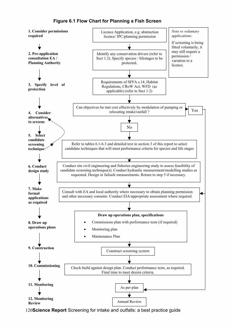
Science Report Screening for intake and outfalls: a best practice guide120
Licence Application, e.g. abstractionlicence/ IPC/planning permission
Requirements of SFFA s.14, HabitatRegulations, CRoW Act, WFD (as
applicable) (refer to Sect 1.2)
1. Consider permissionsrequired
2. Pre-applicationconsultation EA /Planning Authority
3. Specify level ofprotection
4. Consideralternativesto screens
Can objectives be met cost effectively by modulation of pumping orrelocating intake/outfall ? Yes
5. Selectcandidatescreeningtechnique
Refer to tables 6.1-6.3 and detailed text in section 3 of this report to selectcandidate techniques that will meet performance criteria for species and life stages
6. Conductdesign study
Conduct site civil engineering and fisheries engineering study to assess feasibility ofcandidate screening technique(s). Conduct hydraulic measurement/modelling studies as
requested. Design in failsafe measurements. Return to step 5 if necessary.
7. Makeformalapplicationsas required
Consult with EA and local authority where necessary to obtain planning permissionand other necessary consents. Conduct EIA/appropriate assessment where required.
8. Draw upoperations plans
Draw up operations plan, specifications
• Commissions plan with performance tests (if required)
• Monitoring plan
• Maintenance Plan
9. ConstructionConstruct screening system
10. Commissioning Check build against design plan. Conduct performance tests, as required.Final time to meet design criteria.
11. MonitoringAs per plan
12. MonitoringReview Annual Review
No
Figure 6.1 Flow Chart for Planning a Fish Screen
Note re voluntaryapplications:
If screening is beingfitted voluntarily, itmay still require apermission /variation to alicence.
Identify any conservation drivers (refer toSect 1.2). Specify species / lifestages to be
protected.

Science Report Screening for intake and outfalls: a best practice guide 121
Table 6.1 Screening Techniques Suitable for Freshwater Sites
Fish species Life stage
Canal / Industrial / Potable supplies &
Fish farmsThermal Power
Plant
Hydro Electric Power Plant: Low
Head
Hydro Electric Power Plant: High
Head Outfalls
JuvenilePassive Mesh, PWWC, Sub-
gravel intakes, MLES, Acoustic, Light, Bubble
Passive Mesh, PWWC, Coanda, Acoustic, Light,
BubbleAcoustic, Light, Bubble Passive Mesh, Coanda,
Acoustic, Light, Bubble
Smolts
Passive Mesh, Vertical/inclined Bar rack, Coanda, PWWC, Sub-gravel intakes,Rotary Discreen,
Modular Inclined, Louvre, Acoustic, Light, Bubble
Passive Mesh, Vertical/inclined Bar rack,
PWWC, Coanda, Rotary Discreen, Modular Inclined,
Louvre, Acoustic, Light, Bubble
Passive Mesh, Vertical/inclined Bar rack,
Louvre, Acoustic, Light, Bubble
Passive Mesh, Vertical/inclined Bar rack, Coanda, Modular Inclined,
Louvre, Acoustic, Light, Bubble
Adult
Passive Mesh, Vertical/inclined Bar rack, Coanda, PWWC, Rotary Discreen, Sub-gravel intakes, Modular Inclined, Louvre, Electric, Acoustic
Passive Mesh, Vertical/inclined Bar rack, PWWC, Coanda, Rotary
Discreen, Modular Inclined, Louvre, Acoustic, Light,
Passive Mesh, Vertical/inclined Bar rack,
Louvre, Acoustic, Light,
Passive Mesh, Vertical/inclined Bar rack, Coanda, Modular Inclined,
Louvre, Acoustic, Light,
Vertical/Inclined Bar Rack, Electric
Juvenile Passive Mesh, Coanda, PWWC, Sub-gravel intakes
Passive Mesh, Coanda, PWWC
Electric Passive Mesh, Coanda
AdultPassive Mesh, Coanda,
PWWC, Rotary Discreen, Sub-gravel intakes, Modular Inclined,
Electric, Deep channel bypass?
Passive Mesh, Coanda, PWWC, Rotary Discreen, Modular Inclined, Electric,
Deep channel bypass?
Passive Mesh, Electric?, Deep channel bypass?
Passive Mesh, Coanda, Modular Inclined, Electric,
Deep channel bypass?
Vertical/Inclined Bar Rack, Electric
ElverPWWC, Sub-gravel intakes,
MLES, Modular Inclined, Electric, Light
PWWC, Sub-gravel intakes, MLES, Modular Inclined,
Electric, LightElectric?, Light Coanda, Electric, Light
Adult
Passive Mesh, Coanda, PWWC, Rotary Discreen, Sub-
gravel intakes, Modular Inclined, Electric, Light, Deep channel
bypass?
Passive Mesh, Coanda, PWWC, Rotary Discreen, Modular Inclined, Electric,
Light, Deep channel bypass?
Passive Mesh, Electric, Light, Deep channel bypass?
Passive Mesh, Coanda, Modular Inclined, Electric,
Light, Deep channel bypass?
Vertical/Inclined Bar Rack, Electric
JuvenilePassive Mesh, PWWC,
Coanda, Sub-gravel intakes, MLES, Acoustic, Light, Bubble
Passive Mesh, PWWC, Coanda, Acoustic, Light,
BubbleAcoustic, Light, Bubble Coanda, Acoustic, Light,
Bubble
Adult
Passive Mesh, Vertical/inclined Bar, PWWC, Rotary Discreen,
Coanda, Sub-gravel intakes, Modular Inclined, Louvre, Acoustic, Light, Bubble
Passive Mesh, Vertical/inclined Bar,
PWWC, Rotary Discreen, Coanda, Modular Inclined, Louvre, Acoustic, Light,
Bubble
Passive Mesh, Vertical/inclined Bar, Louvre,
Acoustic, Light, Bubble
Passive Mesh, Vertical/inclined Bar,
Coanda, Modular Inclined, Louvre, Acoustic, Light,
Bubble
Vertical/Inclined Bar Rack, Electric
JuvenilePassive Mesh, Coanda, Blank
off bottom,PWWC, MLES, Light, Bubble
Passive Mesh, Coanda, Blank off bottom,PWWC,
Light, Bubble
Blank off bottom, Light, Bubble
Passive Mesh, Coanda, Light, Bubble
Adult
Passive Mesh, Vertical/inclined Bar, Rotary Discreen, Coanda,
PWWC, Blank off bottom, MLES, Modular Inclined, Light,
Acoustic
Passive Mesh, Vertical/inclined Bar, Rotary
Discreen, Coanda, PWWC, Blank off bottom, MLES, Modular Inclined, Light,
Acoustic
Passive Mesh, Vertical/inclined Bar, Blank
off bottom, Light, Acoustic
Passive Mesh, Vertical/inclined Bar, Blank off bottom, Coanda, Modular
Inclined, Light, Acoustic
Salmonids and Coregonids
Lampreys
Eels/Elver
Freshwater coarse fish
Freshwater
Key: Items in emboldened typeface are the most suitable choices but those shown in standard typeface may be suitable in some applications
Freshwater benthics

Science Report Screening for intake and outfalls: a best practice guide122
Fish species Life Stage
Large Thermal Power Plant with Onshore Intake
Large Thermal Power Plant with Offshore Intake
Small Thermal Power Plant / Desalination /
Refineries Outfalls
Smolts
Adult 30-50 mm-spaced Bar Rack
JuvenileAdult 30 mm-spaced Bar
Rack
JuvenileAdultElverAdultJuvenileAdultJuvenileAdultJuvenileAdult
Marine/Estuarine
Shads
PWWC screens where feasible; Velocity Cap with Acoustic, Bubble with Fish Return System otherwise. Keep opening above bed
level.
PWWC screens where feasible; Acoustic, Bubble with Fish Return System otherwise.
PWWC alone or Acoustic, Bubble with Fish Return
System
Salmonids
Lampreys
Eels/Elver
Marine/estuarine benthic
Marine/estuarine demersal
Marine/estuarine pelagic
Table 6.2 Screening Techniques Suitable for Marine Sites
6.2 Multiple Solutions and Non-Screening SolutionsIt is stressed again that screening is not always the best solution. It may be moreeconomic and/or protective to modulate abstraction to avoid seasons, days or times ofthe day when fish are most at risk.In the case of larger coastal abstractions where dozens of species may have to beprotected, a single solution may not be adequate. The best solution found to date forsites where PWWC screening is impractical uses a combination of an acoustic fishdeterrent, which is very effective against pelagics and moderately effective againstdemersal species, and a fish return system which is moderately effective for demersalspecies and offer the best solution for robust benthic flatfishes and rock fishes. Thesystems therefore complement each other well. This combination of methods is used atseveral power plants, including Great Yarmouth, Shoreham, Fawley in England and Doelin Belgium. There are numerous other technology combinations that have shownpromise and which should not be overlooked. These include bubble/acoustic/strobe-lightcombinations, electric and acoustic screens, screen and eel-bypass combinations anduse of turbulent attraction flow to improve guidance in front of screens. Reference toTable 6.3 may suggest other techniques that could be combined to achieve the bestresults for the species present.
6.3 Costs of Different Screening SolutionsThe costs of installing fish screens or barriers are highly site-specific and will depend onwhether the application is new-build or retrofit, what existing structures are present, whatground conditions are like, the degree of exposure to flood- and other damage, whetherpower (if required) is available and many other factors. Table 6.4 attempts to provideindicative costs of some of the main techniques in use described in section 3 of thisGuide. In most cases the costs are for the screening/ barrier hardware only and excludecosts associated with planning and design, consultancy, site investigations andpreparation, installation, commissioning and testing. These likely additional costs mayinflate the overall project cost considerably.

Science Report Screening for intake and outfalls: a best practice guide 123
Pelagic Demersal BenthicPassive Mesh/Wedge-Wire Panels 3.1.1 & 3.2.2 ***** ***** ***** ***** ***** ***** *****Vertical or Inclined Bar Racks 3.1.2 ***** ***** ** *** ***** ***** *****Rotary Disc Screen 3.1.3 **** ? ? *** NS NS NSSmolt Safe' 3.1.4.2 ** NS ? ? NS NS NSCoanda Screen 3.1.4.1 ***** NS ***** ***** NS NS NSPWWC Screens 3.2.1 ***** ***** ***** ***** ***** ***** *****Marine Fish Exclusion System 3.2.4 *** *** *** *** NS NS NSModular Inclined Screen 3.3.1 **** NS **** **** ? ? ?Labyrinth Screen 3.3.2 ***** **** **** *** ? ? ?
Louvre Barrier 3.4.2 ** ? NS ? NS NS NSBubble Curtain 3.4.3 ** ** NS ** ** ** *Electric Screen (GFFB)-intakes 3.4.4 ? ? ? ? NS NS NSElectric Screen (GFFB)-outfalls 3.6.3 **** ? **** **** NS NS NSAcoustic (SPA/Infrasound) 3.4.5 **** **** ** **** ***** **** *Acoustic (BAFF) 3.4.5.8 **** ? NS **** NS NS NSAcoustic (Ultrasound) 3.4.5.11 NS **** NS NS *** NS ?Continuous Light 3.4.6.1 ** ** ** ** NS NS NSStrobe Light 3.4.6.2 ** *** *** *** NS NS NSEel Deep Bypass 3.5.3 NS NS *** NS NS NS NSSurface collectors 3.5.2 *** ? ? *** NS NS NSVelocity Cap 3.4.7 ** *** NS NS *** ** ?Turbulent Attraction Flow 3.5.1 ** ? ? ? ? ? ?
Beh
avio
ural
scre
ens
Type of ScreenMarine
Phys
ical
scre
ens
Relevant section in text
Salmonids Shads Eel & Lampreys
Cyprinids & Other
Freshwater Fish
NSKey: note that the ratings assume that the systems are designed using the appropriate criteria for the application. Not Suitable ** Lowefficiency *** Suitable for some lifestages ****Suitable for most lifestages *****Excellent for most or all lifestages
Table 6.3 Suitability of Screening Techniques for Different Types of Fish

Science Report Screening for intake and outfalls: a best practice guide124
Table 6.4 Approximate purchase costs (£k) for fish screens and barriers. Costs arefor equipment only and exclude installation except where otherwise indicated.
Inland Estuarine/MarineScreen or BarrierType
≤1 m3s-1 10 m3s-1 ≤1 m3s-1 10 m3s-1 50 m3s-1
Positive Exclusion Screens
Flat Mesh Panel,12mm
24 50 30 - -
PWWC Screen,3mm
50 285 70 430 -
MLES 160* 1600* - - -
Under-Gravel Filter 160 - - - -Raked Bar Screen 40 250 40 250 -Coanda-Effect 13-17 - - - -
Smolt-SafeScreen
15 - - -
Rotary Disk Screen 130 - - - -Behavioural Screens
Bubble Curtain 5 15 5 15 75Louvre Screen 24 50 - - -Continuous Light 5 20 - - -Strobe Light 10 40 - - -SPA AcousticBarrier
15 40 15 40-60 80-250
BAFF AcousticBarrier
18 40 - - -
Electric GFFB 10 18 - - -* MLES figures are manufacturers estimated fully installed costs in pounds sterling.
Figures given are based on prices obtained from manufacturers. Three scheme sizes (1,10 and 50m3) have been considered where appropriate – generally the smaller schemesare relatively more costly owing to fixed minimum costs. Also, inland and coastal siteshave been differentiated. This is important because different materials may be requiredfor use in saline waters (e.g. marine grade stainless steel or Cu/Ni alloy), whichincreases costs. No figure is shown in cases where screens are considered unsuitable.
Science Report Screening for intake and outfalls: a best practice guide 125
7 MONITORING OF SCREEN EFFECTIVENESS: RECOMMENDATIONSFOR FURTHER WORK
7.1 IntroductionFrom the review of screening technologies presented in section 3 of this Guide, it is clearthat many different approaches exist and that there has been much innovation in recentyears. The development of new techniques reflects the need to provide cost-effectivesolutions to suit an ever-widening range of circumstances. Often, a technique has beendeveloped for a specific application but if the results look promising others will want to tryit in a different situation. Indeed, it may be arguable that every situation is different andthat the performance of every new fish screening system installed should be evaluated atthe commissioning stage. In practice, comprehensive scientific testing can be very costlyand it makes sense to first answer basic questions on effectiveness from soundlydesigned generic studies. The site-specific questions hopefully can then be addressed ina much more concise test programme where the regulator deems this necessary. Thenature of work appropriate to generic trials and to site-specific commissioning trials isdiscussed below.Solomon (1992) proposed that trialling of different fish screens would be best carried outat a purpose-built facility, e.g. on a disused mill leat. He pointed out a number of merits ofthis approach, e.g. that it would not interfere with operation of an existing abstraction,there would not be issues of operators being unwilling to cooperate with a project aimedat identifying the harm that they are doing and that there would not be operationalconstraints on the manipulation of flow conditions. While these remain valid issues, thebreadth of environments and fish species now being considered mean that a variety ofsuch test sites would be required, covering upland and lowland rivers, canals,lakes/reservoirs and estuarine/coastal locations. Also, it is the experience of the presentauthors that many site owners recognise the benefits to future business of work beingundertaken at their facilities and are willing to cooperate. Cooperation often extends notonly to providing access to sites but also to assisting with test facilities and beingprepared to manipulate flow conditions to suit experiments. In some cases, successfulapproaches have been made through trade associations, a route which is to becommended where possible. In particular, operators have shown most willingness tocooperate with regard to trialling behavioural screens, since where they prove suitable,their capital and operating costs would often be lower than for positive exclusion fishscreens. Further opportunities may arise at newly developed operational sites whentrialling is required as a condition of the planning consent or abstraction, impoundment orland drainage consent.
7.2 Priorities for Generic TrialsThe number of techniques now in use could create an almost unlimited agenda fortesting in order to cover the different environments, species and lifestages and thepossible combinations of techniques. Rather than produce an exhaustive list ofpossibilities, the aim here is to identify where resources would be best directed to meetcurrent needs. Table 7.1 lists the most promising techniques and identifies priorities fortrials along with possible test locations/environments. The choice of techniques isnecessarily subjective.
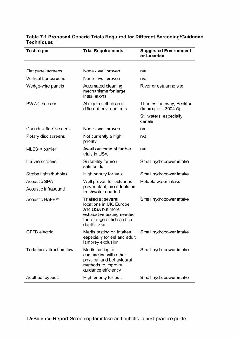
Science Report Screening for intake and outfalls: a best practice guide126
Table 7.1 Proposed Generic Trials Required for Different Screening/GuidanceTechniquesTechnique Trial Requirements Suggested Environment
or Location
Flat panel screens None - well proven n/aVertical bar screens None - well proven n/aWedge-wire panels Automated cleaning
mechanisms for largeinstallations
River or estuarine site
PWWC screens Ability to self-clean indifferent environments
Thames Tideway, Beckton(in progress 2004-5)Stillwaters, especiallycanals
Coanda-effect screens None - well proven n/aRotary disc screens Not currently a high
priorityn/a
MLES barrier Await outcome of furthertrials in USA
n/a
Louvre screens Suitability for non-salmonids
Small hydropower intake
Strobe lights/bubbles High priority for eels Small hydropower intakeAcoustic SPAAcoustic infrasound
Well proven for estuarinepower plant; more trials onfreshwater needed
Potable water intake
Acoustic BAFF Trialled at severallocations in UK, Europeand USA but moreexhaustive testing neededfor a range of fish and fordepths >3m
Small hydropower intake
GFFB electric Merits testing on intakesespecially for eel and adultlamprey exclusion
Small hydropower intake
Turbulent attraction flow Merits testing inconjunction with otherphysical and behaviouralmethods to improveguidance efficiency
Small hydropower intake
Adult eel bypass High priority for eels Small hydropower intake
Science Report Screening for intake and outfalls: a best practice guide 127
7.3 Scope of Work and Costs for Generic Trials
7.3.1 Measures of PerformanceFish screens usually form only part of an overall fish diversion or protection system and itis the performance of the entire system that needs to be proven. Turnpenny et al. (1998)used the concept the scheme passage rate (SPR), defined as:
SPR %= 100*Nleaving/Napproaching,
Where Napproaching, and Nleaving are the numbers of fish approaching and passing thescheme respectively. Although originally referring to hydroelectric schemes, the definitionwill apply to any kind of intake or outfall scheme. This concept assumes that all the fishare uninjured when passing the scheme. Where there is a possibility of fish beingharmed as a result of the scheme, this needs to be taken into account. Examples ofwhere fish might be harmed are:
• during passage through a pump or turbine;
• as a result of contact with screens or other mechanical components of thesystem;
• through predation associated with behavioural changes that make fish an easiertarget for predators.
This can be represented by the following expression:SPR’ %= 100(1-Pi) *Nleaving/Napproaching,
Where Pi represents the probability of fish death or injury. Note that within thisexpression, SPR’ takes the same value whether a fish is injured or killed – i.e. the worstcase is assumed, that any fish injured will not survive.While the SPR’ is the most important measure of a screening system’s performance,another important aspect is the time taken for fish to pass the scheme. This appliesprincipally to off-channel schemes, e.g. hydroelectric schemes where water is divertedthrough a mill-leat before being returned to the main channel. Delays can lead toincreased risk of predation, but this risk is accounted for in the SPR’ expression. Theremay be less clear consequences of delays, for example delayed passage downstreammight put them at some ecological disadvantage. It is not realistic to propose targets forpassage time, as much will be site-specific and will also depend on the physiologicalstate of the fish, water conditions, time of day, etc. Such effects are virtually impossibleto define and the pragmatic course of action is to aim to minimise the time of passage ofa scheme. As part of any off-channel screen trial it is therefore recommended that thetime taken for fish passage should at least be recorded so that comparisons may bemade for different operating conditions or with alternative screen systems tested undercomparable conditions.
7.3.1.1 Test MethodsMethodologies for trials should be aimed at estimating the scheme passage rate (SPR’)and the duration of passage between predefined scheme entry and exit points.However, it is also extremely helpful to observe fish behaviour in the vicinity of screensand bywashes. Where problems occur or scheme passage rates are below desirablelevels, this allows the modes of failure to be identified. A variety of methods can be used.
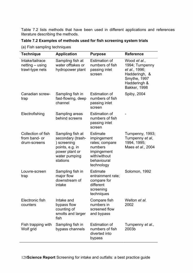
Science Report Screening for intake and outfalls: a best practice guide128
Table 7.2 lists methods that have been used in different applications and referencesliterature describing the methods.Table 7.2 Examples of methods used for fish screening system trials(a) Fish sampling techniques
Technique Application Purpose ReferenceIntake/tailracenetting – usingtrawl-type nets
Sampling fish atwater offtakes orhydropower plant
Estimation ofnumbers of fishpassing inletscreen
Wood et al.,1994; Turnpennyet al., 1996;Hadderingh, &Smythe, 1997Hadderingh &Bakker, 1998
Canadian screw-trap
Sampling fish infast-flowing, deepchannel
Estimation ofnumbers of fishpassing inletscreen
Spiby, 2004
Electrofishing Sampling areasbehind screens
Estimation ofnumbers of fishpassing inletscreen
-
Collection of fishfrom band- ordrum-screens
Sampling fish atsecondary (trash-) screeningpoints, e.g. inpower plant orwater pumpingstations
Estimateimpingementrates; comparenumbersimpingementwith/withoutbehaviouraltechnology
Turnpenny, 1993;Turnpenny et al,1994, 1995;Maes et al., 2004
Louvre-screentrap
Sampling fish inmajor flowdownstream ofintake
Estimateentrainment rate;compare fordifferentscreeningtechniques
Solomon, 1992
Electronic fishcounters
Intake andbypass flowcounting ofsmolts and largerfish
Compare fishnumbers inscreened flowand bypass
Welton et al.2002
Fish trapping withWolf grid
Sampling fish inbypass channels
Estimation ofnumbers of fishdiverted intobypass
Turnpenny et al.,2003b

Science Report Screening for intake and outfalls: a best practice guide 129
(b) Fish observation and monitoring techniques
Technique Application Purpose ReferenceVideosurveillance
Monitoring fish infront of screens &at bypassentrance
To check forevidence of fishimpingement,delay or toobservebehaviour
Larinier &Travade, 1999
Hydroacousticmonitoring
Intake forebays &bypass entrances
Observebehaviour &estimate relativenumbers of fishpassing screensor enteringbywash
7.3.2 Iverson,1999;Johnson etal., 2002
Radio-oracoustic-tagging(biotelemetry)
Observing fishmovementthrough or aroundschemes
Estimation ofSPR and durationof passage
7.3.3 Lariner &Travade,1999
PassiveIntegratedTransponder(PIT) or Floytagging
Monitoring fishmovementthrough or aroundschemes
Estimation ofSPR and durationof passage usingmark-recapture
Larinier &Travade, 1999
Float-tagging Observing fishmovementthrough or aroundschemes
Detailedobservation offish behaviour infront of screensand bypasses;estimation ofSPR and durationof passage
Turnpenny et al.,2003
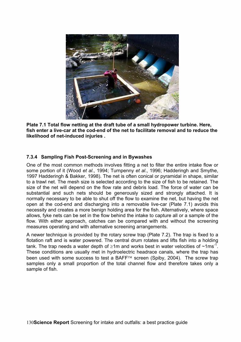
Science Report Screening for intake and outfalls: a best practice guide130
Plate 7.1 Total flow netting at the draft tube of a small hydropower turbine. Here,fish enter a live-car at the cod-end of the net to facilitate removal and to reduce thelikelihood of net-induced injuries .
7.3.4 Sampling Fish Post-Screening and in BywashesOne of the most common methods involves fitting a net to filter the entire intake flow orsome portion of it (Wood et al., 1994; Turnpenny et al., 1996; Hadderingh and Smythe,1997 Hadderingh & Bakker, 1998). The net is often conical or pyramidal in shape, similarto a trawl net. The mesh size is selected according to the size of fish to be retained. Thesize of the net will depend on the flow rate and debris load. The force of water can besubstantial and such nets should be generously sized and strongly attached. It isnormally necessary to be able to shut off the flow to examine the net, but having the netopen at the cod-end and discharging into a removable live-car (Plate 7.1) avoids thisnecessity and creates a more benign holding area for the fish. Alternatively, where spaceallows, fyke nets can be set in the flow behind the intake to capture all or a sample of theflow. With either approach, catches can be compared with and without the screeningmeasures operating and with alternative screening arrangements.A newer technique is provided by the rotary screw trap (Plate 7.2). The trap is fixed to aflotation raft and is water powered. The central drum rotates and lifts fish into a holdingtank. The trap needs a water depth of ≥1m and works best in water velocities of ~1ms-1.These conditions are usually met in hydroelectric headrace canals, where the trap hasbeen used with some success to test a BAFF screen (Spiby, 2004). The screw trapsamples only a small proportion of the total channel flow and therefore takes only asample of fish.

Science Report Screening for intake and outfalls: a best practice guide 131
Plate 7.2 A rotary screw trap. Flow rotates the barrel and fish present in the floware lifted into a holding chamber. The trap takes a small sample of the totalchannel flow.Other kinds of fish trap are also useful. The Wolf trap (Plate 7.3) is essentially adewatering device that can be placed in a bywash channel to remove fish. It comprises aslatted channel floor through which flow passes, leaving the fish to be washed along thesurface of the slats and to drop into a tank or cage at the downstream end. It is probablythe most widely used style of smolt trap and is ideally suited to monitoring fish entering abywash (Turnpenny et al., 2003b). The louvre screen trap described in section 3provides a further alternative which appeared to work well, although the versionconstructed at Walton was a substantial structure that would be more suited to a semi-permanent test facility.
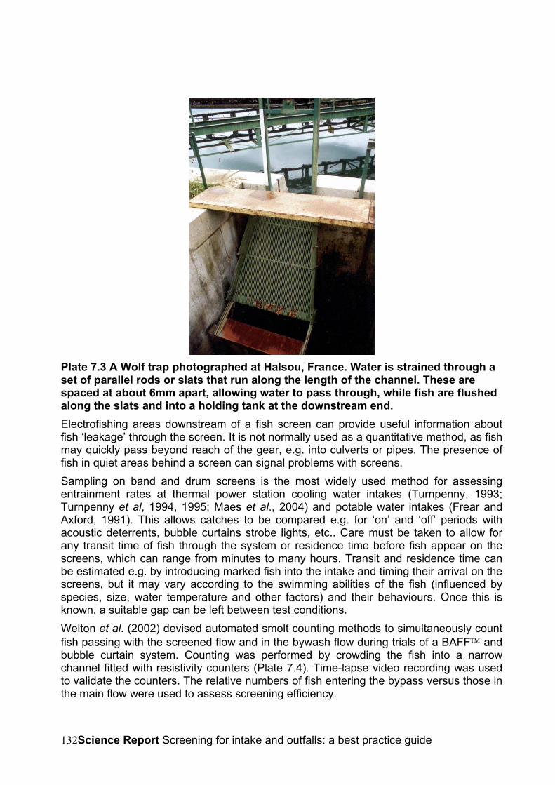
Science Report Screening for intake and outfalls: a best practice guide132
Plate 7.3 A Wolf trap photographed at Halsou, France. Water is strained through aset of parallel rods or slats that run along the length of the channel. These arespaced at about 6mm apart, allowing water to pass through, while fish are flushedalong the slats and into a holding tank at the downstream end.Electrofishing areas downstream of a fish screen can provide useful information aboutfish ‘leakage’ through the screen. It is not normally used as a quantitative method, as fishmay quickly pass beyond reach of the gear, e.g. into culverts or pipes. The presence offish in quiet areas behind a screen can signal problems with screens.Sampling on band and drum screens is the most widely used method for assessingentrainment rates at thermal power station cooling water intakes (Turnpenny, 1993;Turnpenny et al, 1994, 1995; Maes et al., 2004) and potable water intakes (Frear andAxford, 1991). This allows catches to be compared e.g. for ‘on’ and ‘off’ periods withacoustic deterrents, bubble curtains strobe lights, etc.. Care must be taken to allow forany transit time of fish through the system or residence time before fish appear on thescreens, which can range from minutes to many hours. Transit and residence time canbe estimated e.g. by introducing marked fish into the intake and timing their arrival on thescreens, but it may vary according to the swimming abilities of the fish (influenced byspecies, size, water temperature and other factors) and their behaviours. Once this isknown, a suitable gap can be left between test conditions.Welton et al. (2002) devised automated smolt counting methods to simultaneously countfish passing with the screened flow and in the bywash flow during trials of a BAFF andbubble curtain system. Counting was performed by crowding the fish into a narrowchannel fitted with resistivity counters (Plate 7.4). Time-lapse video recording was usedto validate the counters. The relative numbers of fish entering the bypass versus those inthe main flow were used to assess screening efficiency.
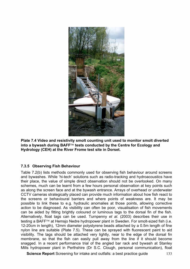
Science Report Screening for intake and outfalls: a best practice guide 133
Plate 7.4 Video and resistivity smolt counting unit used to monitor smolt divertedinto a bywash during BAFF tests conducted by the Centre for Ecology andHydrology (CEH) at the River Frome test site in Dorset.
7.3.5 Observing Fish BehaviourTable 7.2(b) lists methods commonly used for observing fish behaviour around screensand bywashes. While ‘hi-tech’ solutions such as radio-tracking and hydroacoustics havetheir place, the value of simple direct observation should not be overlooked. On manyschemes, much can be learnt from a few hours personal observation at key points suchas along the screen face and at the bywash entrance. Arrays of overhead or underwaterCCTV cameras strategically placed can provide much information about how fish react tothe screens or behavioural barriers and where points of weakness are. It may bepossible to link these to e.g. hydraulic anomalies at those points, allowing correctiveaction to be diagnosed. As visibility can often be poor, visualisation of fish movementscan be aided by fitting brightly coloured or luminous tags to the dorsal fin of the fish.Alternatively, float tags can be used. Turnpenny et al. (2003) describes their use intesting a BAFF at Hemsjo Nedre hydropower plant in Sweden. For smolt-sized fish (i.e.12-20cm in length), 12mm diameter polystyrene beads attached by a 0.5m length of finenylon line are suitable (Plate 7.5). These can be sprayed with fluorescent paint to aidvisibility. The tags should be attached very lightly, near to the edge of the dorsal finmembrane, so that the fish can easily pull away from the line if it should becomesnagged. In a recent performance trial of the angled bar rack and bywash at StanleyMills hydropower plant in Perthshire (Dr S.C. Clough, personal communication), float
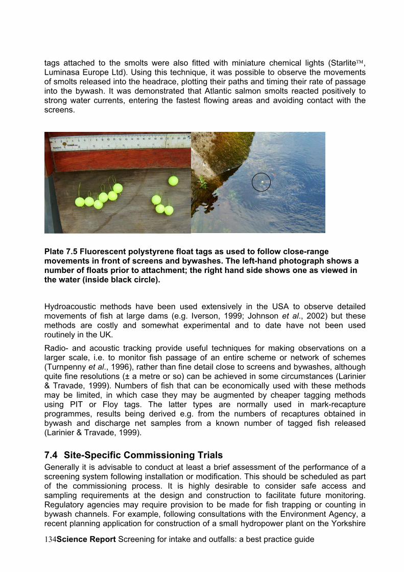
Science Report Screening for intake and outfalls: a best practice guide134
tags attached to the smolts were also fitted with miniature chemical lights (Starlite,Luminasa Europe Ltd). Using this technique, it was possible to observe the movementsof smolts released into the headrace, plotting their paths and timing their rate of passageinto the bywash. It was demonstrated that Atlantic salmon smolts reacted positively tostrong water currents, entering the fastest flowing areas and avoiding contact with thescreens.
Plate 7.5 Fluorescent polystyrene float tags as used to follow close-rangemovements in front of screens and bywashes. The left-hand photograph shows anumber of floats prior to attachment; the right hand side shows one as viewed inthe water (inside black circle).
Hydroacoustic methods have been used extensively in the USA to observe detailedmovements of fish at large dams (e.g. Iverson, 1999; Johnson et al., 2002) but thesemethods are costly and somewhat experimental and to date have not been usedroutinely in the UK.Radio- and acoustic tracking provide useful techniques for making observations on alarger scale, i.e. to monitor fish passage of an entire scheme or network of schemes(Turnpenny et al., 1996), rather than fine detail close to screens and bywashes, althoughquite fine resolutions (± a metre or so) can be achieved in some circumstances (Larinier& Travade, 1999). Numbers of fish that can be economically used with these methodsmay be limited, in which case they may be augmented by cheaper tagging methodsusing PIT or Floy tags. The latter types are normally used in mark-recaptureprogrammes, results being derived e.g. from the numbers of recaptures obtained inbywash and discharge net samples from a known number of tagged fish released(Larinier & Travade, 1999).
7.4 Site-Specific Commissioning TrialsGenerally it is advisable to conduct at least a brief assessment of the performance of ascreening system following installation or modification. This should be scheduled as partof the commissioning process. It is highly desirable to consider safe access andsampling requirements at the design and construction to facilitate future monitoring.Regulatory agencies may require provision to be made for fish trapping or counting inbywash channels. For example, following consultations with the Environment Agency, arecent planning application for construction of a small hydropower plant on the Yorkshire

Science Report Screening for intake and outfalls: a best practice guide 135
Ouse includes provision of a removable Wolf-grid in the bywash channel and a fishholding chamber. At another site where commissioning trials were required, the failure toprovide safe access for sampling proved costly when extensive temporary scaffoldingwas needed.Trial methods for site-specific commissioning may be selected from any of thoseidentified in section 7.3 but for cost reasons the simpler methods are to be preferred.,e.g. trapping, video surveillance or float-tagging. For regulated applications the methodswill need to be agreed with the appropriate agency in advance.

Science Report Screening for intake and outfalls: a best practice guide136
8 KNOWLEDGE GAPS AND FUTURE RESEARCH NEEDS
8.1 Review of recommendations from Solomon (1992)In advice to the National Rivers Authority, Solomon (1992) made a number ofrecommendations in respect of fish screening. These are summarised below, along withan indication of progress made since 1992 and comments on their current relevance.The words shown in quotation marks are paraphrased from Solomon’s.
8.1.1 “A national database on abstractions should be developed to include details of fishprotection stipulations and measures actually fitted.”
A national database of some 48,000 abstractions now exists but details of fish protectionstipulations and measures are not included. This remains a need.
8.1.2 “Staff should be provided with a concise legal summary of legislation pertinent tofish screening and enforcement and that there should be a broadening of existinglegislation to include all types of abstraction and all species of fish.”
Following formation of the Environment Agency in 1995, powers under SFFA 1975 weretransferred to the Agency and a national training programme on fish screeningtechniques and legislation for enforcement staff was undertaken. This Guide providesfurther information on the subject for the benefit of regulatory agencies and the public.Powers to extend the scope of screening as proposed have been recommended in therecent Fisheries Legislative Review. At present they have not been enacted in law.However, a review of SFFA s.14 & 15 under the Environment Act 1995 extended itspower to include fish farm intakes and outfalls.
8.1.3 “Operators should be required to fit appropriate fish screens whenever possible onnew and existing abstractions, subject to provisions of the law.”
Since 1995, the Agency has carried out a national SFFA s.14 enforcement programme atRegional and Area levels. Many intakes that were formerly not provided with fishprotection screening have now been retrofitted with screens or alternative measures (e.g.behavioural technologies), including some that were not legally obliged to do so. Thishas been undertaken following the Agency’s Risk Assessment approach detailed insection 4.2. See also point 8.1.8 below. In England and Wales, provision of fishappropriate screening is also now addressed through conditions attached to abstractionand impoundment licences under the Water Resources Act.
8.1.4 “R & D should be commissioned to investigate the timing, mechanisms and extentof migrations of 0+ and older coarse fish to assist in better defining periods whenabstraction might be stopped.”
The Agency has commissioned work on coarse fish migrations (see review by Lucas etal, 1998: EA Technical Report W152). Other UK research has also since contributed tothis field (see e.g. Smith, 1998; Turnpenny et al, 1998b). However, while knowledge inthis area has improved, regional and between-river differences in seasonal timing are notwell known and further research into geographic differences would help to refine
Science Report Screening for intake and outfalls: a best practice guide 137
operating agreements. There will nevertheless remain a need to retain flexibility in suchagreements to allow for inter-annual variations.
8.1.5 “R & D should be commissioned to investigate distribution and dispersiondynamics of coarse fish to aid in sympathetic siting of intakes (including diurnalpatterns, swimming depths, etc.).”
No significant advance has been made in this field and further research is required.
8.1.6 “R & D should be commissioned to investigate population control mechanisms in0+ fish to assess impact of losses at various life-stages.”
Work by Smith (1998) and Turnpenny (1999) used the Equivalent Adult Value (EAV)concept (section 2.2), which enables comparisons of impacts of various life-stages butomits any density-dependent population control effects.Given the inherent difficulties in quantifying the compensatory capacity associated withdensity-dependent effects (Van Winkle, 1977), it is probably more useful to assume thatno compensation takes place and act accordingly. The Equivalent Adult approach is aneffective tool for this purpose. While this has been used by Smith (1998) and Turnpenny(1989) to make some attempt at quantifying population level impacts, both authors wereaware that the outputs are only as good as the life-history data entered into the analysis.Such data (age-specific mortality and reproductive rates, sex ratios) are presently sparseand are likely to be somewhat specific to particular river conditions, fish communities andeven years. The most pressing research need in this context is therefore to assemblelife-history data sets for particular species. This might best be done in the first instanceby investigating benchmark communities representative of key habitat types (lakes,upland streams and rivers, lowland streams and rivers etc.). The benefits of suchresearch would no doubt spill over into other areas of fisheries biology and managementand therefore might be funded from multiple sources.
8.1.7 “R & D should be commissioned to investigate screen slot and mesh sizessuitable for different species and lifestages.”
Earlier work reported by Turnpenny (1981) is considered to provide an adequate basisfor calculating mesh size for the majority of species, based on the body-length/body-diameter relationship (‘fineness ratio’). Further work is however needed to clarify themore complex relationship between slot-width, channel velocity, fish body length andexclusion efficiency for PWWC screens. This area is currently being researched in theUSA and any new data from those studies should be investigated before commissioningnew UK work. As the PWWC screen is one of the most important screening techniquescurrently available, good information on these aspects is essential and work should becommissioned if data are not found elsewhere.
8.1.8 “R & D should be commissioned to investigate the extent of fish entrapment atintakes in England and Wales.”
Some work in this field, described in section 2 of this Guide, has beenundertaken since Solomon’s (1992) recommendations, particularlypertaining to thermal and hydropower generating plant. As the main large-volume water abstractors, there remains a need to investigate potentialimpacts from power plant abstractions, either through commissioned R & D
Science Report Screening for intake and outfalls: a best practice guide138
or owner-funded studies. The latter currently account for most of the studiescarried out in this field, usually as a result of conditions attached tooperating licences but in some cases volunteered by the owners. Futurework should concentrate in particular on designated fish species (seesection 1.2), especially lampreys, on entrainment of fish eggs, larvae and frythat are usually not fully represented in power station sampling and on otherspecies of conservation interest such as sea trout, smelt and eel.
The little work that has been carried out at potable water and fish farmabstractions (e.g. at Walton on Thames and the Hampshire Avon – section2) suggests that impacts on coarse fish through fry entrainment arepotentially large and significant (Turnpenny, 1999), although the importanceof high entrainment counts is hard to judge in the absence of a clearunderstanding of the population dynamics. All evidence indicates thatredistribution movements of fry in rivers put large numbers at risk ofentrainment and the absence of data on fry movements in particular waterbodies should not be used as an excuse for not taking adequate screeningmeasures to protect fry. Wherever possible, through legislative provisions orvoluntary cooperation, owners should be encouraged to ensure protectionof all life stages of fish. This may be best achieved through screeningmeasures, or through temporal modulation of flow to avoid abstractionduring periods of high entrainment risk.
8.2 Additional Recommendations for R & DThe need for adequate site trials of different existing screening technologies wasaddressed in section 7, where the purpose of the proposed studies was to test thesuitability and efficiency of different techniques for the variety of species and applicationsof interest. The aim here is to consider particular gaps in either our understanding ofimpacts or the armory of available techniques not covered in previous discussion. Someare identified below. Undoubtedly others will become apparent when looking intoindividual project applications.
8.2.1 Juvenile fish mortalities and injuries in hydroelectric turbinesSection 4 refers to techniques used to quantify fish mortalities in turbines. Numericalmodelling techniques have been validated on fish of smolt size and larger and appear toprovide adequate predictions of mortality rates for impact assessment purposes(Turnpenny et al., 1998, 2000). Theory and empirical laboratory evidence (Turnpenny,1988) indicate that mortality rates due to blade strike - the major cause of injuries insmolts- are relatively much lower in small fish (<20g) than for smolt-sized fish. Thisresults from the larger surface area-to-mass ratio in small fish, which causes the water todrag them around the blade’s leading edge, whereas the momentum of larger fish makescollision more probable. The present STRIKER turbine fish injury model developed byTurnpenny et al. (2000) does include terms to account for pressure flux and turbulence(shear stress) effects, which may also contribute to fish injury risk, but the empirical dataused were derived for smolt-sized and larger fish, therefore they may be unreliable inapplication to juveniles.At present, no lowland river hydropower schemes in England and Wales are known toprovide screening of sufficiently small mesh opening to prevent the entry of coarse fishfry. For low-head, run-of river schemes the inherent hydraulic head-loss caused by low
Science Report Screening for intake and outfalls: a best practice guide 139
porosity screens make them impractical and uneconomic. From theory it has beenassumed that fry mortalities would be negligible. There is now an urgent need to test thisassumption through monitoring at operational lowland river sites and to modify predictivemodels as necessary.
8.2.2 Eel and lamprey screening and guidance methodsThese elongate, thin-bodied fish are poor swimmers and present particular problems withregard to fish screening. Where it is practicable to use fine-meshed or wedge-wirescreens, it has been shown that both species can be effectively screened down tojuvenile sizes. At large abstractions, especially at thermal and hydropower generationsites, small aperture screens are not always practicable; these species are particularly atrisk of blade strike during passage through hydroelectric turbines. While a number ofbehavioural guidance techniques have shown promise, none is currently sufficientlydeveloped to recommend.The main contenders for behavioural guidance of these species at present are:
• strobe lights
• low-frequency sound
• water currents
• electric fields.All of these methods should be investigated, individually and in combination. Juvenileand adult eels and lampreys should be included in tests. Tests would best be carried outin the headrace of one or more small hydropower stations where hydraulic conditionsare relatively well controlled. A number of suitable sites have been identified.One further technique of interest is the bed-level eel bypass channel such as installed atBackbarrow hydropower scheme on the R. Leven in Cumbria and elsewhere in Europe(see section 3.5.3). It is not clear how effective this device is, nor whether it could beimproved with better hydraulic conditions but available evidence suggests that it is atleast partially effective under some flow conditions. This method merits furtherconsideration as an adjunct to other screening and guidance methods. In particular, it willbe necessary to observe the detailed behaviour of eels confronted with this type ofbypass and to be able to manipulate the dimensions and geometry of the structure. Suchan approach would lend itself to testing in a laboratory flume or raceway, where thebehaviour of eels and lampreys could be observed.
8.2.3 Behavioural Barriers in GeneralOwing to the potential cost savings and ease of use, there is considerable interest fromoperators in using behavioural barriers as an alternative to positive exclusion fishscreens for a wider range of species. This is particularly true of low-head run-of-riverhydropower schemes, which use large volumes of water and where screening costs arecomparatively high and hydraulic losses may limit generating revenues (see Turnpennyet al., 1998a). Although behavioural techniques have advanced, scientific trial results arestill limited and regulatory agencies are reluctant to accept their use in many situations.The cost of conducting scientific trials to a sufficiently rigorous standard can be too highfor individual operators of small schemes to bear and therefore further generic testing isrecommended. Sites of existing or proposed schemes on the rivers Trent (e.g. Beeston),

Science Report Screening for intake and outfalls: a best practice guide140
Yorkshire Ouse (e.g. Linton), Thames (various) and some Scottish rivers may providesuitable locations.
Science Report Screening for intake and outfalls: a best practice guide 141
9 REFERENCES
Aitken, P.L., Dickerson, L.H. and Menzies, W.J.M., 1966. Fish passes and screens atwater power works. Proc. Inst. Civil Eng., 35: 29-57.
Amaral, S.V., Taft, E.P., Winchell, F.C., Plizga, A., Paolini, E. and Sullivan, C.W.(1999). Fish diversion effectiveness of a modular inclined screen system. In:Innovations in Fish Passage Technology, Odeh, M (ed).
Anon., 1990. Task Force monitoring results for the Salt River Project’s electrical fishbarriers below granite reef Dam-South and Arizona Canal electrical fish barriers.Unpublished report, US Dept of the Interior, Bureau of Reclamation, ArizonaProjects Office, 23636 N. 7th St, PO Box 9980, Phoenix, Arizona, USA: 5 pp.
Anon., 1994. Emigration of juvenile clupeids and their responses to light conditions atthe Cabot Station, fall 1993. Unpublished report by RMC Environmental Services,Drumore, Pennsylvania, USA.
Anon., 1995. Notes for guidance on the provision of fish passes and screens for the safepassage of salmon. Scottish Office Agriculture and Fisheries Department. HMSO: 38pp.
Anon.., 1996a. Testing of an acoustic smolt deflection system, Blantyre HydroelectricPower Scheme. ETSU H/01/00046/REP: 90 pp.
Anon.., 1996b. Hydroelectric development in Scotland and its effects on fish. ScottishHydroelectric plc, 10 Dunkeld Road, Perth, PH1 5WA: 70 pp.
Aprahamian, M.W. and Jones, G.O. (1989). Usk salmon smolt investigations – 1989.National Rivers Authority, Technical Memorandum No. PL/EaE/89/34.
Arnold, G.P., 1974. Rheotropism in fishes. Symp. Zool. Soc. London. 5: 13-32.Bainbridge, R. 1961. Problems of fish locomotion. Symp. Zool. Soc. London., 5:13-32Bamber, R.N. and Turnpenny, A.W.H., 1986. Trial of a Johnson 715 alloy wedge-wire
screen at an UK coastal site. Report No. TPRD/L/3012/R86, Central ElectricityResearch Laboratories, CEGB, London.
Bartel, R., Bieniarz, K. and Epler, P., 1993. Fish passing through the turbines of 4hydroelectric plants situated on Slupia River. Roczniki Nukowe PZW, 6: 137-142.
Bartel, R., Bieniarz, K. and Epler, P., 1996. Fish passing through the turbines ofhydroelectric plant in Kamienna on Drawa River. Roczniki Nukowe PZW, 9: 23-28.
Barwick, D.H. and Miller, L.E., 1994. Effectiveness of an electrical barrier in blockingfish movement. Proceedings of the Annual Conference of the SoutheastAssociation of Fish and Wildlife Agencies: 19 pp.
Bates, D.W. and Visonhaler, R., 1956. The use of louvres for guiding fish. Trans. Am.Fish. Soc., 86: 38-57.
Beamish, F.W.H. 1978. Swimming Capacity. In Fish Phyisiology. W. S. Hoar. London,Academic Press.: 101-187.
Ben-Yami, M., 1976. Fishing with Light. Surrey, England, Fishing News Books Ltd: 121pp.
Science Report Screening for intake and outfalls: a best practice guide142
Bestgen, K.R. et.al. 2000. Exclusion and survival rates of early life stages of fatheadminnows released over coanda effect wedge wire screens, Draft report submitted tometro wastewater reclamation district, Denver, Colorado.
Booth, R.K., Bombardier, E.B., McKinley, R.S., Scruton, D.A. and Goosney, R.F. (inpress). Swimming performance of post spawning adult (kelts) and juvenile (smolts)Atlantic salmon, Salmo salar. Can. J. Fish. Aquat Sci., MS No. 2406.
Blaxter, J.H.S. (1969). Swimming Speeds of Fish, FAO Fisheries Report, No. 62 Vol. 2.:28 pp.
Bramsaes, F., Morgens, J. and Otterstrom, C.V. (1942). Barriers against fishes bymeans of electricity of veils of air: Rept. Danish. Biol. Stn., 47: 39-.
Brett, J.R. and MacKinnon, D. (1953). Preliminary experiments using lights andbubbles to deflect migrating young spring salmon. J. Fish. Res. Bd Canada, 10:548-559.
Brown, A., 1997. The application of Coanda effect screens in SHP. Proceedings of theHidroenergia 97 conference, September 29th – October 1st, 1997, Dublin, Ireland:190-200.
Brown, R.E. (1997b). Utilization of strobe lighting as a cost-effective deterrent for fishturbine mortality. Paper presented at the EPRI Fish Passage Workshop, Milwaukee,Wisconsin, May 6th-8th 1997. Electric Power Research Institute, Palo Alto, USA.
Brujis, M.C.M., Hadderingh, R.H. and Jenner, H.A. (2002). Deflecting eels from waterintakes with light. International Conference on methods and techniques inBehavioural Research, Amsterdam, The Netherlands.
Buerkett, C.G. (1994). Passage and Behaviour of Adult American Shad in an ExperimentalLouver Bypass System. Thèse de maîtrise en science présentée à University ofMassachusetts Amherst, Department of Forestry and Wildlife Management.
Carlson, T.J. (1995). Use of sound for fish protection at power production facilities: ahistorical perspective of the state of the art. Phase 1 Final Report: Evaluation of theuse of sound to modify the behavior of fish., No. DOE/BP-62611-4, July 1995.Bonneville Power Administration, Public Information Center - CKPS-1, PO Box 3621,Portland, OR 97208, USA.
Coutant, C.C. (2001). Turbulent attraction flows for guiding juvenile salmonids at dams.American Fisheries Society Symposium 26: 57-77.
Cramer, D.P. (1997). Evaluation of a louvre guidance system and Eicher screen for fishprotection at the T W Sullivan Plant in Oregon. American Fisheries Society 127th
Annual Meeting, “Fisheries at Interfaces: Habitats, Disciplines, Cultures”, Monterey,CA, 24-28th August 1997. Abstracts.
Coggan, R.A. and Dando, P. (1988). Movements of juvenile Dover sole, Solea solea(L.), in the Tamar Estuary, South-western England. J. Fish Biol. 33 (suppl. A): 177-184.
Crawford, W.G. (1994). The Foyle Fisheries Commission - an example of cross-borderfishery conservation and protection. Institute of Fisheries Management,Proceedings of the 25th Annual Study Course, University of Lancaster, 13-15th
September, 1994: 189-199.

Science Report Screening for intake and outfalls: a best practice guide 143
Dankel, D. (1999). The lower snake river juvenile salmon migration feasibilityreport/environmental impact assessment: Surface bypass and collection. The USarmy corps of engineers.
Ducharme, L.J.A. (1972). An application of louvre deflectors for guiding Atlantic salmon(Salmo salar) smolts from power turbines. J. Fish. Res. Bd Canada, 29: 1397-1404.
Ferguson, J.W., Poe, T.P. and Carlson, T.J. (1997). Surface-orientated bypasssystems for juvenile salmonids on the Columbia River, USA. In: Fish Migration andFish Bypasses (Ed. Jungwirth, M., Schmutz, S. and Weiss, S.). Fishing NewsBooks, Oxford, Blackwell:281-299.
Fields, P.E., Murray, A.K., Johnson, D.E. and Finger, G.L., (1958). Guiding migrantsalmon by light repulsion and attraction in fast and turbid water. Technical ReportNos 36 and 41, College of Fisheries, Unioversity of Washington, Seattle, WA, USA.
Frear, P.A. and Axford, S.N. (1991). Impingement and mortality of fish associated withthe R. Ouse abstraction scheme. National River Authority, Yorkshire Region,Fisheries Science Report No. 62/91.
Goetz, F.A., Dawson, J.J, Shaw, T, Dillon, J. (2001). Evaluation of low-frequencysound transducers for guiding salmon smolts away from a navigation lock.American Fisheries Society Symposium 26: 91-104.
Goosney, R., (1997). An efficient diversion/bypass system, for Atlantic salmon (Salmosalar) smolt and kelt in power canals. Text of poster paper presented at the EPRIFish Passage Workshop, Milwaukee, Wisconsin, May 6th-8th 1997. Electric PowerResearch Institute, Palo Alto, USA.. R. Goosney, Chief Engineer (salmonids),Fisheries and Oceans, PO Box 5667, St John’s, Newfoundland, A1C 5X1, Canada.
Hadderingh, R. (1982). Experimental reduction of fish impingement by artificialillumination at Bergum power station. Int. Rev. ges. Hydrobiol., 67: 887-900.
Hadderingh, R.H. and Bakker, H.D. (1998). Fish mortality due to passage throughhydroelectric power stations on the Meuse and Vecht Rivers. Proc. Int. Conf. on“Fish Migration and Fish By-pass Channels”, Vienna, Austria, September 24-26th,1997. Fishing News Books.
Hadderingh, R.H. and Smythe, A.G. (1997). Deflecting eels from power stations withlight. Paper presented at the EPRI Fish Passage Workshop, Milwaukee, Wisconsin,May 6th-8th 1997. Electric Power Research Institute, Palo Alto, USA.
Hanson, B.N. (1979). Studies of three cylindrical profile-wire screens mounted parallel toflow direction. Passive Intake Screens Workshop, Chicago, Illinois, December 1979.Johnson Division UOP Inc., Surface Water Screen Department, New Brighton,Minnesota, USA:97-107.
Harden Jones, F.R. (1963). The reaction of fish to moving backgrounds. J. exp. Biol. 40:437-446.
Hilgert, P.J. (1992). Evaluation of a graduated electric field as a fish exclusion device.Final report to Puget Sound Power and Light Co., Environmental Sciences, PO Box97034, Bellevue, Washington 98009-9734, USA: 29 pp.#
Holmes, R.H.A. (1975). Fish and weed on Fawley Generating Station screens, February1973-January, 1974. Central Electricity Generating Board, Publication No.CERL/L/N129/75.

Science Report Screening for intake and outfalls: a best practice guide144
Howarth, W. (1987). Freshwater Fishery Law. London, Blackstone: 311 pp.Haro, A., Odeh, M., Noreika, J. and Castro-Santos, T. (1998). Effects of water
acceleration on downstream migratory behaviour and passage of Atlantic salmonsmolts and juvenile American shad at surface bypasses. Trans. Am. Fish. Soc., 127(1): 118-127.
Hawkins, A.D. (1981). The hearing abilities of fish. In: Hearing and Sound Communicationin Fishes. Springer-Verlag, New York: 109-133.
Hawkin, A.D. and Johnstone, A.D.F. (1978). The hearing of the Atlantic salmon, Salmosalar. J. Fish Biol., 13: 655-673.
Heuer, J.H. and Tomljanovich, D.A. (1979). A further study on the protection of fishlarvae at intakes using wedge-wire screening. Technical Note B33, Division ofWater Resources, Tennessee Valley Authority, Norris, Tennessee 37826, USA.
Hocutt, C.H. and Edinger, J.E. (1980). Fish behaviour in flow fields. In: Power Plants,London, Academic Press, 143-180
Homa, J. Jr, Stafford-Glase, M. and Connors, E. (1994). An evaluation of theeffectiveness of the strobe light deterrent system at Milliken Station on Cayuga Lake,Tompkins County, New York. Unpublished report by Ichthyological Associates, Inc, 50Ludlowville Rd, Lansing, New York, 14882-9023, USA: 34 pp + figs & tables.
Jerkø, H., Tarunen-Rise, I., Enger, P.S. and Sand, O. (1989). Hearing in eel (Anguillaanguilla). J. Comp. Physiol. A, 165, 455-459.
Johnson, P.N., Goetz, F.A. and Ploskey, G.R. (2001). Evaluation of strobe lights forvertically displacing juvenile salmon near a filling culvert intake at the Hiram M.Chittenden locks, Seattle, Washington. American Fisheries Society Symposium26:13-25.
Johnson, R.L. Simmons, M.A., Simmons, C.S., and Blanton, S.L. (2002). A newmultibeam sonar technique for evaluating fine-scale fish behaviour near hydroelectricdam structures. In: Behavioural Technologies for Guidance of Fish. AmericanFisheries Society Symposium 26: 161-170.
Klinect D., Loeffelman P.H. and Van Hassel J.H. (1992). A new signal developmentprocess and sound system for diverting fish from water intakes. Proc. Amer. PowerConference, Illinois Institute of Technology, April 13-15, 1992, Chicago, Illinois.
Kostecki, P.T., Clifford, p., Gloss, S.P. and Carlisle, J.C. (1987). Scale loss andsurvival in smolts of Atlantic salmon (Salmo salar) after turbine passage. Can. J.Fish. Aquat. Sci., 44: 210-214.
Knudsen, F.R., Enger, P.S. and Sand, O. (1992). Awareness reactions and avoidanceresponses to sound in juvenile Atlantic salmon. J. Fish Biol., 40: 523-534.
Knudsen, F.R., Enger, P.S. and Sand, O. (1994). Avoidance responses to low frequencysound in downstream migrating juvenile Atlantic salmon. J. Fish Biol., 45 (2): 227-233.
Knudsen, F.R., Schreck, C.B., Knapp, S.M., Enger, P.S. and Sand, O. (1997).Infrasound produces flight and avoidance responses in Pacific juvenile salmonids. J.Fish Biol., 51: 824-829.
Kynard, B. and Buerkett, C. (1997). Passage and behavior of adult American shad in anexperimental louver bypass system. N. Am. J. Fish. Manage. Vol. 17 (3): 734-742.

Science Report Screening for intake and outfalls: a best practice guide 145
Lambert, D.R., Turnpenny, A.W.H. and Nedwell, J.R. (1997). The use of acoustic fishdeflection systems at hydro stations. Hydropower and Dams, Issue 1, 1997: 54-56.
Larinier, M. and Boyer-Bernard, S. (1991). Devalaison des smolts et efficacite d’unexutoire de devalaison a l’usine hydroelectrique d’Halsou sur la Nive. Bull. Francaisde la Peche et de la Pisciculture 321: 72-92.
Larinier, M. and Travade, F. (1991). The development and evaluation of downstreambypasses for juvenile salmonids at small hydroelectric plants in France. In:Innovations in Fish Passage Technology (ed. Odeh, M.), American FisheriesSociety, Bethesda, Maryland, USA: 25-42.
Lemon, D.D., Wittinger, R.J., Cartier, W.W. and Emmert, R. (2000). Effect of aprototype surface collector and juvenile fish diversion screens on turbine efficiencymeasured at Unit 5, Bonneville Dam. US Army Corps of Engineers.
Liu, L. and He, D. (1988). The reaction of five freshwater fishes to a movable bubblecurtain. J. Xiamen. Univ., 27(2): 214-219.
Loeffelman P.H., Van Hassel J.H., Klinect D.A., 1991(a). Using sound to divert fish fromturbine intakes. Hydro Review, October, 1991: 30-43.
Loeffelman P.H., Klinect D.A. & Van Hassel, J.H., 1991(b). Fish protection at waterintakes using a new signal development process and sound system. In 'Waterpower'91', Amer. Soc. Civ. Engrs: 355-365.
Love, M.S., Sandhu, M., Stein, J., Herbinson, K., Moore, R.H., Mullins, M. andStephens, J.S., Jr (1987). Analyses of diversion efficiencies and survivorship of theSan Onofre Nuclear Generating Station fish return system. Unpublished report,Southern California Edison, Rosemead, CA, USA.
Lucas, M.C., Thom, T.J, Duncan, A. and Slavik, O. (1998). Coarse fish migration:occurrence, causes and implications. Environment Agency R & D Technical ReportW152, 161pp.
Maes, J., Peeters, B, Ollevier, F., Parmentier, A., Thoelen, E., Franchois, H., Turnpenny,A.W.H., Lambert, D.J. and Nedwell, J.R. (1999). Evaluation of the fish guidancesystem at the cooling water inlet of the Nuclear Power Plant Doel 3 / 4. Unpublishedreport to Electrabel, Doel. Catholic University of Leuven, Leuven, Belgium.
Maes, J., Turnpenny, A.W.H., Lambert, D., Nedwell, J.R., Parmentier, A., Ollevier,F. (2004). Field evaluation of a sound system to reduce estuarine fish intake ratesat a power plant cooling water inlet (Doel, Belgium). J. Fish Biol. 64,: 938:946.
Mallen-Cooper, M. (1997). Developing fishways for non-salmonid fishes: a case studyfrom the Murray River in Australia. American Fisheries Society 127th AnnualMeeting, “Fisheries at Interfaces: Habitats, Disciplines, Cultures”, Monterey, CA, 24-28th August 1997. Abstracts.
Maiile, M.A., Harryman W. and Ament, W. (2001). Response of free-ranging kokaneeto strobe lights. In: Behavioural Technologies for Guidance of Fish. AmericanFisheries Society Symposium 26: 27-35.
Mann, D.A., Lu, Z. and Popper, A.N. (1997). A clupeid fish can detect ultrasound.Nature, 389, 25 September 1997, p. 341.
Science Report Screening for intake and outfalls: a best practice guide146
Matthews, J.G and Taylor, J.W. (1994). Design and construction of Eicher penstockfish screens. Paper presented to the Canadian Electrical Association, Toronto,March 1994. BC Hydro, 6911 Southpoint Drive, Burnaby, BC, V3N 4X8.Internet: www.Interchg.ubc.ca/bchydro/environment/programs/puntledge2.html
McDowell, R.M. (1988). Diadromy in fishes. London, Croom Helm, 308pp.Moursund, R.A., Dauble, D.D. and Langeslay, M.J. (2003). Turbine intake diversion
screens: investigating effects on Pacific lamprey. Hydro Review, March 2003: 40-46Nedwell, J.R. and Turnpenny, A.W.H. (1997). Fish guidance using evanescent sound.
American Fisheries Society 127th Annual Meeting, “Fisheries at Interfaces: Habitats,Disciplines, Cultures”, Monterey, CA, 24-28th August 1997.
Nedwell, J.R. and Turnpenny, A.W.H, Lovell, J., Langworthy, J., Howell, D. andEdwards, B. (2003). The effects of underwater noise from coastal piling on salmon(Salmo salar) and brown trout (Salmo trutta). Subacoustech Report to theEnvironment Agency (Southern Region), No. 576R0112, Subacoustech Ltd, ChaseMill, Bishops Waltham, Hants., Dec. 2003.
Nemeth R.S and Anderson, J.J. (1992). Response of juvenile coho and chinooksalmon to strobe and mercury lights. N. Amer. J. Fish. Mgmt, 12: 684-692
Nordland, B. (1996). Designing fish screens for fish protection at water diversions.National Marine Fisheries Service, 525 N.E. Oregon, Suite 500Portland, Oregon 97232, USA (download from:www.nwr.noaa.gov/1hydrop/hydroweb/docs/usfws_97.htm).
Odeh, M and Orvis, C. (1998). Downstream fish passage considerations anddevelopments at hydroelectric projects in North-east USA. In: Fish Migration andFish Bypasses (Ed. Jungwirth, M., Schmutz, S. and Weiss, S.). Fishing NewsBooks, Oxford, Blackwell: 267-280.
Office of Technology Assessment (1995). Fish Passage Technologies: Protection atHydropower Facilities. OTA-ENV-641- Washington, DC: US Government PrintingOffice.
Patrick, P.H. and Poulton, J.S. (2001). Responses of American eels to strobe lightsand sound (preliminary data) and introduction to sound conditioning as a potentialfish passage technology. In: Behavioural Technologies for Guidance of Fish.American Fisheries Society Symposium, 26: 1-11.
Patrick, P.H., Christis, A.E., Sager, D.R., Hocutt, C.H and Stauffer, J.R. (1985).Responses of fish to strobe light/air-bubble barrier. Fisheries Research 3, 157-172.
Patrick, P.H., Sheeham, R.W. and Sim, B. (1982). Effectiveness of a strobe light eelexclusion scheme. Hydrobiologia, 94, 269-277.
Pavlov, D.S. (1989). Structures assisting the migrations of non-salmonid fish: USSR.FAO Fisheries Technical Paper No. 308. Rome, Fisheries and AgricultureOrganization of the United Nations: 97 pp.
Peake, S., McKinley, R.S. and Scruton, D.A.(1997). Swimming performance of variousfreshwater Newfoundland salmonids relative to habitat selection and fishwaydesign. J. Fish Biol. 51: 710-723.
Science Report Screening for intake and outfalls: a best practice guide 147
Peake, S. and McKinley, R.S. (1998). A re-evaluation of swimming performance injuvenile salmonids relative to downstream migration. Can. J. Fish. Aquat. Sci., 55:682-687.
Rainey, W.S. (1985). Considerations in the design of juvenile bypass systems.Proceedings of the Symposium on Small Hydropower and Fisheries, May 1-3, 1985,Aurora, Colorado, USA. American Fisheries Society, 5410 Grovsenor Lane, Suire110, Bethesda, Maryland, USA: 261-268.
Richkus, W. (2001). Review and documentation of research and technologies on thepassage and protection of downstream migrating catadromous eels at hydroelectricfacilities. Final Report to the Electric Power Research Institute No. 1000730,November 2001, EPRI Customer Fulfillment, 1355 Willow Way, Suite 278, Concord,CA94520, USA.
Rozicj, T. J. (1989). Evaluation of the Pere Marquette River electrical lamprey barrier.Unpublished report, Fisheries Division, Michigan Department of Natural Resources:19 pp.
Ruggles, C. P. (1982). What’s new in downstream fish passage? In: Salmon in the Seaand New Enhancement Strategies, 4th International Atlantic Salmon Symposium(Ed. D.H. Mills). Oxford, Blackwell: 402-416.
Ruggles, C. P. (1990). A critical review of fish exclusion systems for turbine intakes withparticular reference to a site on the Connecticut River, USA. Proc. InternationalSymposium on Fishways ’90 in Gifu , Japan October 8-10:151-156.
Ruggles, C.P. and Ryan, P. (1964). An investigation of louvres as a method for guidingjuvenile Pacific salmon. The Department of Fisheries for Canada, Canadian FishCulturist, 33.
Sager, D.R., Hocutt, C.H. and Stauffer, J.R. (1987). Estuarine fish responses to strobelight, bubble curtains and strobe light/bubble curtain combinations as influenced bywater flow rate and flash frequencies. Fish. Res. : 383-399.
Salmon Advisory Committee (1997). Fish Passes and Screens for Salmon. Report ofthe Salmon Advisory Committee. London, MAFF Publications: 69 pp.
Sand, O. and Karlsen, H.E. (1986). Detection of infrasound by Atlantic cod. J. Exp.Biol., 125: 197-204.
Sand, O., Enger, P.S., Karlsen, H.E. and Knudsen, F.R. (2001). Detection ofinfrasound in juvenile salmonids and European silver eels: a mini-review. AmericanFisheries Society Symposium 26: 183-193.
Saunders, W.P. (1997). Effectiveness of above-water lighting in improving bypassefficiency. Paper presented at the International Symposium Implementing andAdvancing Fish Passage Technology, Surface Bypass and Collection ofOutmigrating Fish, 24-28 August, 1997, Monterey, California. 127th Annual Meetingof the American Fisheries Society.
Schuler, V.J. and Larson, L.E. (1975). Improved fish protection at intake systems. J.Engrg Div. ASCE, 101, (EE6): 897-910.
Seelye, J.G. (1989). Evaluation of the Ocquedoc River electrical weir for blocking sealampreys. Unpublished report, US Fish and Wildlife Service, Hammond BayBiological Station, 11188 Ray Road, Millersburg, MI 49759, USA: 8pp.
Science Report Screening for intake and outfalls: a best practice guide148
Simmons, R. (2000). Effectiveness of a fish bypass with an angled bar rack at passingatlantic salmon and steelhead trout smolts at the Lower Saranac hydroelectricproject. In: Advances in fish passage technology, Odeh, M. (ed).
Smith, K. (1998). Fish entrapment at inland power stations. PhD Thesis, University ofNottingham, May 1988: 177 pp.
Solomon D.J. (1992). Diversion and entrapment of fish at water intakes and outfalls. R &D Report No. 1, National Rivers Authority, Bristol: 51 pp.
Spiby, D. (2004). A pilot study into the effectiveness of a bubble/acoustic screen designedto divert migrating fish away from hydroelectric turbines. Unpublished report,Environment Agency, North-West Region, February 2004.
Taylor, R. M., Pegg, M. A. and Chick, M.H. (in press). Effectiveness of two bioacousticbehavioral fish guidance systems for preventing the spread of bighead carp to theGreat Lakes. The North American Journal of Fisheries Management.
Thatcher, K. (1992). Behaviour of 0-group cyprinids in relation to entrainment in riverinecooling-water systems. Fawley Aquatic Research Laboratories Ltd, Report No. FCR020/92.
Therrien, J. and Bourgeois, G. (2000). Fish passage at small hydro sites. A report bythe Genivar Consulting Group for CANMET Energy Technology Centre.
Thorpe, J E and Morgan, R.I.G. (1978). Periodicity in Atlantic salmon Salmo salar L. smoltmigration. J.Fish Biol., 12: 541-548.
Travade, F. Bertrand Y. and Coulon, G. (1983). Étude comparative de deux systems derécuperation d'organisms entraines dans les prises d'eau de la centrale du Blayais.Électricité de France, Report No. HE/31.83.17, 32 pp + figures + plates + tables.
Travade, F. and Larinier, M. (1992). La migration de devalaison: problemes etdispositifs. Bulletin Francais de la Peche et de la Pisciculture, 326—327: 165-176.
Truebe, J.P. and Truebe, E.P. (1997). Current inducer and downstream bypass systemat Upper Penacook Hydroelectric plant, July 1997. Prepared by Lakesideengineering, Inc., Mirror Lake, New Hampshire, for Essex Hydro Associates,Boston.
Truebe, J.P and Truebe, E.P. (1998). 1998 fish passage report for Upper PenacookFalls. Prepared by Lakeside engineering, Inc., Mirror Lake, New Hampshire, forEssex Hydro Associates, Boston.
Turnpenny, A.W.H. (1981). An analysis of mesh sizes required for screening fishes atwater intakes. Estuaries, 4(4):363-368.
Turnpenny, A.W.H. (1988). The behavioural basis of fish exclusion from coastal powerstation cooling water intakes. CEGB Internal Publication No. RD/L/3301/R88.
Turnpenny, A.W.H. (1989). Impoundment and abstraction - exclusion of fish fromintakes. In: “Water Schemes: the Safeguarding of Fisheries” (Ed. Gregory, J).Pitlochry, Atlantic Salmon Trust.
Turnpenny, A.W.H. (1993). Bubble curtain fish exclusion trials at Heysham 2 PowerStation. Fawley ARL Ltd, Client Report to Nuclear Electric plc, Report No. FCR037/93.

Science Report Screening for intake and outfalls: a best practice guide 149
Turnpenny, A.W.H. (1997). An appraisal of fish screening requirements for raw waterintakes on the River Thames. Fawley ARL Ltd, Client Report to Thames WaterUtilities, No. FCR 243/97.
Turnpenny, A.W.H. (1999). Review of potential for coarse fish entrainment at potablewater intakes on the lower freshwater Thames (Hurley-Teddington). Fawley ARLLtd, Client Report to the Environment Agency, Thames Region, No. FCR 302/99.
Turnpenny, A.W.H. (1998). Mechanisms of fish damage in low-head turbines: anexperimental appraisal. In: Fish Migration and Fish Bypasses (Ed. Jungwirth, M.,Schmutz, S. and Weiss, S.). Fishing News Books, Oxford, Blackwell: 300-314.
Turnpenny, A.W.H. and Hanson, K.P. (1997). Fish passage through small hydro-turbines: theoretical, practical and economic perspectives. Proceedings of theHidroenergia 97 conference, September 29th – October 1st, 1997, Dublin, Ireland:451-463.
Turnpenny, A.W.H. & Nedwell, J.R. (1994). The effects on marine fish, divingmammals and birds of underwater sound generated by seismic surveys. Report tothe UK Offshore Operators Association No. FRR 089/94. Fawley Aquatic ResearchLaboratories Ltd, Fawley, Southampton SO45 1TW, UK.
Turnpenny, A.W.H., Thatcher, K.P., Wood, R. & Loeffelman, P.H. (1993). Experimentson the use of sound as a fish deterrent. Fawley Aquatic Research Laboratories Ltd,report to the Energy Technology Support Unit (ETSU), Harwell, Didcot, OxfordshireOX11-ORA, Contractors Report No. ETSU T/04/00171/REP.
Turnpenny, A.W.H., Thatcher, K.P., Wood, R. (1994). Fish deterrent trials at HinkleyPoint power station, Somerset, 1993-1994. Fawley Aquatic Research LaboratoriesLtd, report to the Energy Technology Support Unit (ETSU), Harwell, Didcot,Oxfordshire OX11-ORA, Contractors Report No. ETSU T/04/00198/REP.
Turnpenny, A.W.H., Fleming, J.M., Thatcher, K.P., Wood, R. (1995). Trials of anacoustic fish deterrent system at Hartlepool Power Station. Fawley Aquatic ResearchLaboratories Ltd. Client Research Report to Nuclear Electric plc, No. FCR 163/95.
Turnpenny, A.W.H., Mackenzie, S., Blay, Somes, R. and Struthers, G. (1996).Biological testing of an acoustic barrier at Blantyre Hydro-electric station, RiverClyde. FAWLEY arl Ltd, Report no. FCR 208/96.
Turnpenny, A.W.H, Struthers, G. and Hanson, K .P. (1998a). A UK Guide to IntakeFish-Screening Regulations, Policy and Best Practice. Contractors report to theEnergy Technology Support Unit, Harwell, Project No. ETSU H/00052/00/00
Turnpenny, A. W. H., Blay, S. R., Jeffreys, K. and Lawton, K. (1998b). Trial of a "SPAacoustic fish barrier to reduce fish entrainment at Farmoor raw water intake, RiverThames, Summer 1998. Fawley Aquatic Research Laboratories Ltd, ConsultancyReport No. FCR 298/98.
Turnpenny, A.W.H. and Taylor, C.J.L. (2000). An assessment of the effect of theSizewell power stations on fish populations. Hydroecologie Applique, 12, 87-134.
Turnpenny, A.W.H., Clough, S.C. Hanson, K.P, Ramsay, R. and McEwan, D. (2000).Risk assessment for fish passage through small, low-head turbines. Contractorsreport to the Energy Technology Support Unit, Harwell, Project No ETSUH/06/00054/RP, 55pp.

Science Report Screening for intake and outfalls: a best practice guide150
Turnpenny, A.W.H. and Coughlan, J. (2003). Using Water Well: Studies of PowerStations and the Aquatic Environment. Innogy plc, Swindon, UK, 142 pp.
Turnpenny, A.W.H. and Nedwell, J.R., Maes, J., Taylor, C.J.L. and Lambert, D.(2003a, in press). Development and operation of acoustic fish deterrent systems atestuarine power stations. Proceedings of the United States EnvironmentalProtection Agency Symposium on Cooling Water Intake Technologies, WashingtonDC, USA, May 2003.
Turnpenny, A.W.H. and Nedwell, J.R. and Lambert, D. (2003b, in press). Reactions offish to acoustic barriers. Proceedings of the Bioengineering Symposium, AmericanFisheries Society, Baltimore, August 2002.
Van Winkle, W. (1977) (Ed). Assessing the effects of power plant induced mortaility onfish populations. New York, Pergamon: 380 pp.
Wardle, C.S. (1975). Limit of fish swimming speed. Nature. 225: 725-727.Welton, J.S., Beaumont, W.R.C., Ladle, M., Dear, B.E. and Masters, J.E. (1995).
Smolt trapping using acoustic techniques. Analysis of results of the 1995 smolt run.Report to NRA South Western Region, CEH Project No., T11064K5, IFE Report No.RL/T11064K5/3. Institute of Freshwater Ecology, Rivers Laboratory, Dorset: 18pp.
Welton, J.S., Beaumont, W.R.C. and Clarke, R.T. (2002). The efficacy of air, soundand acoustic bubble screens in deflecting Atlantic salmon, Salmo salar L., smolts inthe River Frome, UK. Fisheries Management and Ecology, 9; 1: 11-18.
Wert, M.A., Carey, D.W. and Neece, R.E. (1987). Hydraulic model evaluation of theEicher passive pressure screen fish by-pass system. Research Project 1745-18,Final Report AP-5492, Electric Power Research Institute, 3412 Hillview Ave., PaloAlto, CA 94304, USA.
Wood, R., Thatcher, K.P., Woodcock, A. and Turnpenny, A.W.H. (1994). Fish deterrenttrials at the River Foss Pumping Station, York, 1993-1994. FAWLEY aquaticresearch laboratories Ltd, Report to the National Rivers Authority, No. FIR 087/94.
Science Report Screening for intake and outfalls: a best practice guide 151
10 GLOSSARYThe following are definitions of certain words and abbreviations used in this Guide:
AFD – ‘Acoustic fish deterrent system’ – a behavioural screen or barrier exploiting thehearing sensitivity of fish.
Acoustic barrier – Barriers which exploit the hearing sensitivity of fish.
Approach velocity – The velocity of water approaching the screen.
Attraction flow – A water flow which attracts fish to a desired area.
Backflush – Reverse of flow to wash off debris from the screen.
BAFF – ‘Bioacoustic fish fence’ – a combined sound and bubble curtain screeningsystem.
Behavioural barrier or screen – A fish deterrent system which works by stimulating thesenses of fish either by repulsion or attraction mechanisms.
Benthic – Bottom dwelling fish.
Biofouling – the build up of aquatic organisms on a substrate.
Bubble curtain or barrier – A wall of bubbles used to deflect or guide fish.
Bypass – A channel or pipe which allows fish to pass by the obstruction unharmed viaan alternative route.
Bywash – Synonymous with ‘bypass’ (see above) but more commonly used in Britain
Channel velocity – The velocity in front of the screen measured axial to the flowchannel.
Coanda effect – Principle of how fluids follow a surface identified by Henri Coanda in1910.
Science Report Screening for intake and outfalls: a best practice guide152
Diadromous – Migratory species that move between the sea and freshwater and viceversa.
Epibenthic – Species that normally live close to the bed.
Escape velocity – The water velocity perpendicular to the face of the screen.
Entrainment – The drawing-in of fish of any lifestage at a water intake
Euryhaline – Species with a wide tolerance of salinities
GFFB – ‘Graduated field fish barrier’ – a form of electric screen which presents anelectric field of increasing intensity (voltage) as the fish gets closer, generated bymeans a series of separate pulse generators
Impingement – The accidental pinning of fish onto the surface of a screen by the watercurrent
Infrasound – Sound with a frequency of less than 20Hz
Kelt – Stage in a salmon life cycle just after spawning.
Lithophilous – Requiring gravel on which to spawn.
MLES – ‘Marine life exclusion system’ – a water-permeable geotextile barrier.
MSSS –‘Maximum sustainable swimming speed’
Phototaxis – Movement in relation to light.
Pinhead fry – Newly hatched fry.
PWWC – Passive wedge wire cylinder – a type of fine aperture screen suitable for fishexclusion down to fry size
Retrofit –Addition of equipment to existing facilities.
Science Report Screening for intake and outfalls: a best practice guide 153
Rheotactic – Movement (of fish or other animal) in relation to flow.
SAC – ‘Special area of conservation’.
Shear (hydraulic) – Differential velocity field in water
Smolt – Young salmon of 2 or 3 years old.
SPA – ‘Sound projector array’ – uses arrays of underwater transducers to produce adiffuse field of sound.
SSSI – Site of Special Scientific Interest
Strobe light – High intensity, short duration light pulses.
Teleost – A bony fish.
Transformer – Recently metamorphosed pre-adult lamprey

We welcome views from our users, stakeholders and the public, includingcomments about the content and presentation of this report. If you are happywith our service, please tell us about it. It helps us to identify good practice andrewards our staff. If you are unhappy with our service, please let us know howwe can improve it.


