41
Original Instructions_MNL_TTB342BTE_GB_V01_130925 TTB579PLN 1500W Jointer Planer Barcode: 5052931253685 WARNING! Read the instructions before using the product!

Orig
inal
Inst
ruct
ions
_MN
L_TT
B34
2BTE
_GB
_V01
_130
925
TTB579PLN
1500W Jointer Planer
Barcode: 5052931253685
WARNING! Read the instructions before using the product!

1500W JOINTER PLANER TTB342BTE
Congratulations on your purchase of a TITAN power tool fromTITAN Power Tools (UK) Ltd. We want you to continue getting thebest performance from it so this handbook includes informationon safety, handling and care. Please retain this handbook in caseyou need to refer to any of the information in the future.Your TITAN power tool comes with a 2 year guarantee, so shouldit develop a fault within this period contact your retailer.
This TITAN product carries a 2 year guarantee. If your product develops a fault within thisperiod, you should, in the first instance contact the retailer where the item was purchased.This guarantee specifically excludes losses caused due to:- Fair wear and tear- Misuse or abuse- Lack of routine maintenance- Failure of consumable items (such as batteries)- Accidental damage- Cosmetic damage- Failure to follow manufacturer’s guidelines- Loss of use of the goodsThis guarantee does not affect your statutory rights. This guarantee is only valid in the UK.
GUARANTEE

TTB579PLN by TITAN GBIE
03
2028363940
In more detail...
Product functionsCare and maintenanceTrouble shootingRecycling and disposalEC declaration of conformity
19
03
040515
Getting started...
Your productTechnical and legal informationBefore you start
These instructions are for your safety. Please read through them thoroughlybefore use and retain them for future reference.
Let’sget started…
TTB579PLN by TITAN
Get
ting
star
ted
...
GB
04
Your product
Your product
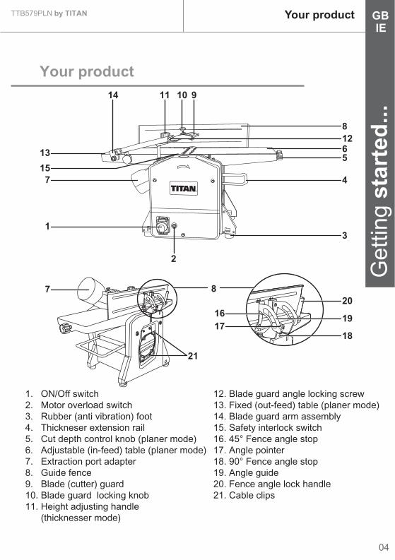
1. ON/Off switch2. Motor overload switch3. Rubber (anti vibration) foot4. Thickneser extension rail5. Cut depth control knob (planer mode)6. Adjustable (in-feed) table (planer mode)7. Extraction port adapter8. Guide fence9. Blade (cutter) guard10. Blade guard locking knob11. Height adjusting handle (thicknesser mode)
12. Blade guard angle locking screw13. Fixed (out-feed) table (planer mode)14. Blade guard arm assembly15. Safety interlock switch16. 45° Fence angle stop17. Angle pointer18. 90° Fence angle stop19. Angle guide20. Fence angle lock handle21. Cable clips
IE
820
19
18
21
16
1
2
7
13
15
7
17
3
4
56128
101114 9

TTB579PLN by TITAN
05
Get
ting
star
ted
...Technical and legal
information
Technical specifications
General> Input Voltage> Power Input> No Load Speed> Max. Planing Width> Max. Depth of Cut (Planer)> Max. Depth to Cut (Thicknesser)> Planing Height> Feed Speed> Table Size
> Net Weight
:::::::::
:
230-240V~50Hz
1500W
9000min-1
204mm
3mm
2mm
5-120mm (Thicknesser)
6m/min (Thicknesser)
740x212mm (Planer)
270x204mm (Thicknesser)
26.5kg
VIBRATIONThe European Physical Agents (Vibration) Directive has been brought in to helpreduce hand arm vibration syndrome injuries to power tool users. The directiverequires power tool manufacturers and suppliers to provide indicative vibration testresults to enable users to make informed decisions as to the period of time a powertool can be used safely on a daily basis and the choice of tool.Further Advice can be found at www.hse.gov.uk
The declared vibration emission value should be used as a minimum level andshould be used with the current guidance on vibration.Calculating the actual period of the actual period off use can be difficult and the HSEwebsite has further information.
The declared vibration emission been measured in accordance with a standardisedtest stated above and may be used to compare one tool with another.
Sound power level L WA : 105.9dB(A)Sound level according toEN 61029
Work mode description 1(if required by the relevant Part 2)
Vibration total values (triax vector sum) determined according to EN 61029:
Sound pressure level L pA : 92.9dB(A)
Uncertainty K pA, K WA : 3dB(A)
Vibration emission value ah = 3.0m/s2
Uncertainty K = 1.5m/s2
GBIE
TTB579PLN by TITAN
Get
ting
star
ted
...
GB
06
IE
The declared vibration emission value may also be used in a preliminaryassessment of exposure.
Technical and legalinformation
Warning! The vibration emission value during actual use of the power tool can differ from the declared value depending on the ways in whichthe tool is used dependant on the following examples and other variationson how the tool is used:How the tool is used and the materials being cut or drilled.The tool being in good condition and well maintained.The use the correct accessory for the tool and ensuring it is sharp and in goodcondition.The tightness of the grip on the handles.And the tool is being used as intended by its design and these instructions.
This tool may cause hand-arm vibration syndrome if its use is notadequately managed Warning! identify safety measures to protect the operator that are based on an estimation of exposure in the actual conditions of use (taking accountof all parts of the operating cycle such as the times when the tool is switched offand when it is running idle in addition to the trigger time).Note The use of othertools will reduce the users’ total working period on this tool.
Helping to minimise your vibration exposure risk.ALWAYS use sharp chisels, drills and blades.Maintain this tool in accordance with these instructions and keep well lubricated(where appropriate)Avoid using tools in temperatures of 10ºC or less.Plan your work schedule to spread any high vibration tool use across a numberof days.Health SurveillanceAll employees should be part of an employer’s health surveillance scheme tohelp identity any vibration related diseases at an early stage, prevent disease progression and help employees stay in work.
Important noteRemove the mains plug from socket before carrying out any adjustmentor servicing.Ensure your mains supply voltage is the same as your tool rating plate voltage.

TTB579PLN by TITAN Technical and legalinformation
07
Get
ting
star
ted
...GBIE
Additional safety warning for construction dust The updated Control of Substances Hazardous to Health Regulations 1st October2012 now also targets to reduce the risks associated with silica, wood and gypsumdusts.Construction workers are one of the at-risk groups within this because of the dustthat they breathe: silica dust is not just a nuisance; it is a real risk to your lungs!
Silica is a natural mineral present in large amounts in things like sand, sandstoneand granite. It is also commonly found in many construction materials suchas concrete and mortar. The silica is broken into very fine dust (also known asRespirable Crystalline Silica or RCS) during many common tasks such as cutting,drilling and grinding Breathing in very fine particles of crystalline silica can lead tothe development of:Lung cancerSilicosisChronic Obstructive Pulmonary Disorder (Chronic obstructive pulmonary disease(COPD))
And breathing in fine particles of wood dust can lead to the development of Asthma
The risk of lung disease is linked to people who regularly breathe construction dustover a period of time, not on the odd occasion.To protect the lung, the COSHH Regulations sets a limit on the amount of thesedusts that you can breathe (called a Workplace Exposure Limit or WEL) whenaveraged over a normal working day. These limits are not a large amount of dust:when compared to a penny it is tiny – like a small pinch of salt:This limit is the legal maximum; the most you can breathe after the right controlshave been used.
How to reduce the amount of dust? 1. Reduce the amount of cutting by using the best sizes of building products.2. Use a less powerful tool e.g. a block cutter instead of angle grinder.3. Using a different method of work altogether – e.g. using a nail gun to direct fasten cable trays instead of drilling holes first.
Please always work with approved safety equipment, such as those dust masksthat specially designed to filter out microscopic particles and use the dust extractionfacility at all time. For more information please see the HSE website:http://www.hse.gov.uk/construction or http://www.hse.gov.uk/pubns/cis69.pdf

Symbols
Safety warnings
TTB579PLN by TITAN
Get
ting
star
ted
...
GB
08
IETechnical and legal
information
WARNING! When using electric tools basic safety precautionsshould always be followed to reduce the risk of fire, electric shockand personal injury including the following.Read all these instructions before attempting to operate this productand save these instructions
On the product, the rating label and within these instructions you will find amongothers the following symbols and abbreviations.Familiarise yourself with them to reduce hazards like personal injuries and damageto property.
V~Wm/minmin-1
yyWxx
VoltInput powerMetres per minutePer minuteManufacturing date code; year of manufacturing (20yy) and weekof manufacturing (Wxx);
HzkgdB(A)
HertzKilogramDecibel (A-rated)
GENERAL SAFETY INSTRUCTIONS
Caution / Warning. Wear hearing protection.
Read the instructionmanual.
Wear eye protection.
Wear respiratory protection.Wear gloves.
The product complies with the applicable European directives and anevaluation method of conformity for these directives was done.
Switch the product off and disconnect it from the power supply beforeassembly, cleaning, adjustments, maintenance, storage and transportation.
WEEE symbol. Waste electrical products should not be disposed ofwith household waste. Please recycle where facilities exist.Check with your Local Authority or local store for recycling advice.
09
TTB579PLN by TITAN Technical and legalinformation
Get
ting
star
ted
...GBIE
SAVE THESE INSTRUCTIONS1. Keep work area clear.> Cluttered areas and benches invite injuries.2. Consider work area environment> Do not expose tools to rain.> Do not use tools in damp or wet locations.> Keep work area well lit.> Do not use tools in the presence of flammable liquids or gases.3. Guard against electric shock> Avoid body contact with earthed or grounded surfaces (e.g. pipes, radiators, ranges, refrigerators).4. Keep other persons away> Do not let persons, especially children, not involved in the work touch the tool or the extension cord and keep them away from the work area.5. Store idle tools> When not in use, tools should be stored in a dry locked-up place, out of reach of children.6. Do not force the tool> It will do the job better and safer at the rate for which it was intended.7. Use the right tool> Do not force small tools to do the job of a heavy duty tool.> Do not use tools for purposes not intended; for example do not use circular saws to cut tree limbs or logs.8. Dress properly> Do not wear loose clothing or jewellery, they can be caught in moving parts.> Non-skid footwear is recommended when working outdoors.> Wear protective hair covering to contain long hair.9. Use protective equipment> Use safety glasses.> Use face or dust mask if working operations create dust.10. Connect dust extraction equipment> If the tool is provided for the connection of dust extraction and collecting equipment, ensure these are connected and properly used.11. Do not abuse the cord> Never yank the cord to disconnect it from the socket Keep the cord away from heat, oil and sharp edges.12. Secure work> Where possible use damps or a vice to hold the work. It is safer than using your hand.13. Do not overreach

> Keep proper footing and balance at all times.14. Maintain tools with care> Keep cutting tools sharp and clean for better and safer performance.> Follow instruction for lubricating and changing accessories.> Inspect too l cords periodically and if damaged have them repaired by an authorised service facility.> Inspect extension cords periodically and replace if damaged.> Keep handles dry, clean and free from oil and grease.15. Disconnect tools> When not in use, before servicing and when changing accessories such as blades, bits and cutters, disconnect tools from the power supply.16. Remove adjusting keys and wrenches> Form the habit of checking to see that keys and adjusting wrenches are removed from the tool before turning it on.17. Avoid unintentional starting> Ensure switch is in “off” position when plugging in.18. Use outdoor extension leads> When the tool is used outdoors, use only extension cords intended for outdoor use and so marked.19. Stay alert> Watch what you are doing, use common sense and do not operate the tool when you are tired.20. Check damaged parts> Before further use of tool, it should be carefully checked to determine that it will operate properly and perform its intended function.> Check for alignment of moving parts, binding of moving parts, breakage of parts, mounting and any other conditions that may affect its operation.> A guard or other part that is damaged should be properly repaired or replaced by an authorised service centre unless otherwise indicated in this instruction manual.> Have defective switches replaced by an authorised service centre.> Do not use the tool if the switch does not turn it on and off.21. Warning> The use of any accessory or attachment other than one recommended in this instruction manual may present a risk of personal injury.22. Have your tool repaired by a qualified person> This electric tool complies with the relevant safety rules. Repairs should only be carried out by qualified persons using original spare parts, otherwise this may result in considerable danger to the user.23. If the replacement of the supply cord is necessary, this has to be done
TTB579PLN by TITAN
Get
ting
star
ted
...
GB
10
IETechnical and legal
information

11
TTB579PLN by TITAN Technical and legalinformation
Get
ting
star
ted
...GBIE
by the manufacturer or his agent in order to avoid a safety hazard.24. For tools intended to be connected to a water supply> For tools provided with a PRCD: Never use the tool without the PRCD delivered with the tool,> For tools provided with an isolating transformer: Never use the tool without the transformer delivered with the tool or of the type as specified in these instructions.> Replacement of the plug or the supply cord shall always be carried out by the manufacturer of the tool or his service organisation,> Keep water clear off the electrical parts of the tool and away from persons in the working area.
HEALTH ADVICE Warning! When drilling, sanding, sawing or grinding, dust particles will be produced. In some instances, depending on the materials you are workingwith, this dust can be particularly harmful to you (e.g. lead from old gloss paint).You are advised to consider the risks associated with the materials you are workingwith and to reduce the risk of exposure. You should:- Work in a well-ventilated area.- Work with approved safety equipment, such as those dust masks that are speciallydesigned to filter microscopic particles.
SPECIFIC SAFETY INSTRUCTIONS Caution! If used incorrectly, woodworking machines can be dangerous, for this reason always comply with the safety instructions mentioned in thismanual.> Never work without the protective equipment prescribed for the relevant operation and do not make any modifications to the machine that could undermine safety.> Children and young persons must not operate this machine. This rule does not apply to young persons over the age of 16 being trained and supervised by an expert.> Prior to all work, make sure that the safety and operating equipment is securely attached. Any parts, if damaged must be repaired correctly or replaced.> Set up the machine on a firm flat surface so that the table is horizontal and the machine cannot tip over.> Never work with pieces which are too big or too small for the machine’s capacity.> Before planing, examine the workpiece for metal objects and stones and remove them if necessary.

> When planing, make sure that the portion of the cutter head not being used is covered by the cutter guard.> When planing thin pieces of timber, suitable devices must be used to ensure that these small pieces are properly positioned and guided.> The anti-kickback device of the planer must be checked regularly to ensure that it remains in proper working condition. All pawls of this device must move freely and must drop down by their own weight when lifted. The point of these pawls must be kept sharp.> Do not begin planing until the cutter head has reached full speed.> When planing, take up a working position so that you are always on one side of the machine away from the area directly in front of or behind the cutter head.> Always keep your hands well away from the cutter head or the chip ejection area while the machine is running.> A uniform feed rate when planing increases the life of the cutting blades and reduces the risk of accidents.> The planing blades must be sharpened or replaced in good time as blunt knives do not only increase the risk of kickback, but also impose an unnecessary load on the motor.> The sawdust created by planing can make it difficult to see as clearly as necessary and can impair the operator’s health in certain circumstances.> If not working outdoors or in a well ventilated area, the machine should ideally be connected to an extractor unit with an air velocity of at least 20 m/s (65.6 ft/sec.).> The sound pressure level at the workplace generally exceeds 85 dB (A), Users should therefore wear ear protectors.> Any repairs to the planer thicknesser must be carried out only by a suitably qualified person.> Only original spare parts and accessories must be used, Otherwise the manufacturer does not offer any warranty and does not accept any liability for personal injury.> Regular cleaning of the machine is an important safety factor, before beginning this task always ensure the planer is turned off and that the plug is removed from the mains supply.
ADDITIONAL SAFETY INSTRUCTIONS FOR JOINTER PLANER WARNING! Before connecting the tool to the mains supply be sure that the voltage supply is the same as that specified on the nameplate of thetool. A power source with a voltage greater or lower than that specified for thetool can result in serious injury to the user, as well as damage to the tool. If indoubt, do not plug the tool into the mains supply. Always turn the machine off andremove the plug from the mains socket before making any adjustments or
TTB579PLN by TITAN
Get
ting
star
ted
...
GBIE
Technical and legalinformation
12
13
TTB579PLN by TITAN Technical and legalinformation
Get
ting
star
ted
...GBIE
maintenance, including changing the blades.> When an extension cable is required, you must ensure that it has the right ampere rating and a large enough cross section for the planer thicknesser, it should also be checked to make sure that no damage is present and it is in safe electrical condition.> Ensure that you have removed foreign objects such as nails and screws front the work before commencing.> Rags, cloths, cord, string and anything that could get “dragged” into the cutter block should be removed from the work area prior to use.> Damaged or contaminated work pieces may cause unwanted hazards. Metal parts penetrated into the workpiece can be very dangerous, and should be removed before operation starts.> Use safety equipment including safety goggles or shield, ear protection, dust mask and protective clothing.> Check to make sure that all fixing screws are tight before operating the tool.> Ensure that the dust extractor is in place before commencing operation.> Do not force the workpiece through the machine, let the machine apply the correct automatic feed rate.> Keep the feed rollers free of wood chips and sawdust, if the movement becomes clogged, kickback can occur.> The machine is designed for the planing of wood only. Never to cut recesses, tennons or moulds.> Do not use the machine for planing wood with numerous knots or loose knots.> Do not stand directly in front of the machine during operation, stand to one side.> Check that the blades are fitted correctly before commencing operation.> Take care when handling blades and the cutter head. Wear work gloves, The blades are sharp and can easily cut bare hands.> Allow the machine to reach full speed before feeding in a workpiece.> Check that the cutters are securely fastened.> Check the amount of cut on the blade before feeding in a workpiece.> Check that the cutters are securely fastened.> Check the amount of cut on the blade before using the machine.> Never attempt a heavy cut in short stock.> Avoid cutting across the grain.> Use the push pads to keep your hands well away from the blades, particularly for shorter stick planing. Do not attempt to feed work pieces that are shorter than the minimum length specified in the technical data of the tool.> Advance the material to the cutting head for normal operation by sliding it along the table, never by placing it directly on the cutting head.

> Never leave the machine set to a heavy cut, always reduce it to a minimum cut.> Use cutting blades designed for this machine only.> Rectify the faults including guards and cutter block immediately as they are discovered.> The machine is equipped with an interlock switch. It only works after the dust extractor is mounted and the switch is closed. Make sure you have already mounted the whole machine otherwise it does not work.> CAUTION: Always mount the dust extractor to the machine for the machine safety.
TTB579PLN by TITAN
Get
ting
star
ted
...
GBIE
Technical and legalinformation
14

Unpack
> Unpack all parts and lay them on a flat, stable surface.> Remove all packing materials and shipping devices if applicable.> Make sure the delivery contents are complete and free of any damage. If you find that parts are missing or show damage do not use the product but contact your dealer. Using an incomplete or damaged product represents a hazard to people and property.> Ensure that you have all the accessories and tools needed for assembly and operation. This also includes suitable personal protective equipment.
You will need
(items not supplied)> Suitable personal protective equipment> Phillips screwdriver> Sharp-nose pliers> Combination square
(items supplied)> 3mm, 5mm, 6mm Hex key (3pcs)> 8 x 10mm Spanner (1 pc)> Blade setting block (1 pc)
Fitting the rubber (anti-vibration) feet
> Carefully turn the machine upside down, taking care not to damage the in-feed / out-feed beds.> Fit the washers M8 (22) over the hex bolts M8 x 20mm (23) and push both through the holes in the rubber feet (3).> Fit the feet / bolts to the holes provided (1 on each corner of the machine).> Secure using the 6mm hex key supplied.
15
TTB579PLN by TITAN Before you startGBIE
WARNING! Do not connect to power supply until assemblyis complete. Failure to comply could result in accidental startingand possible serious injury.
Get
ting
star
ted
...

Before you startTTB579PLN by TITAN
Get
ting
star
ted
...
GB
16
IE
Fitting the guide fence
> Locate the 2 x guide fence mounting holes situated on the side of the planning out-feed table (13). (Fig. 3)> Then place the safety guard plate (24). (Fig. 4)
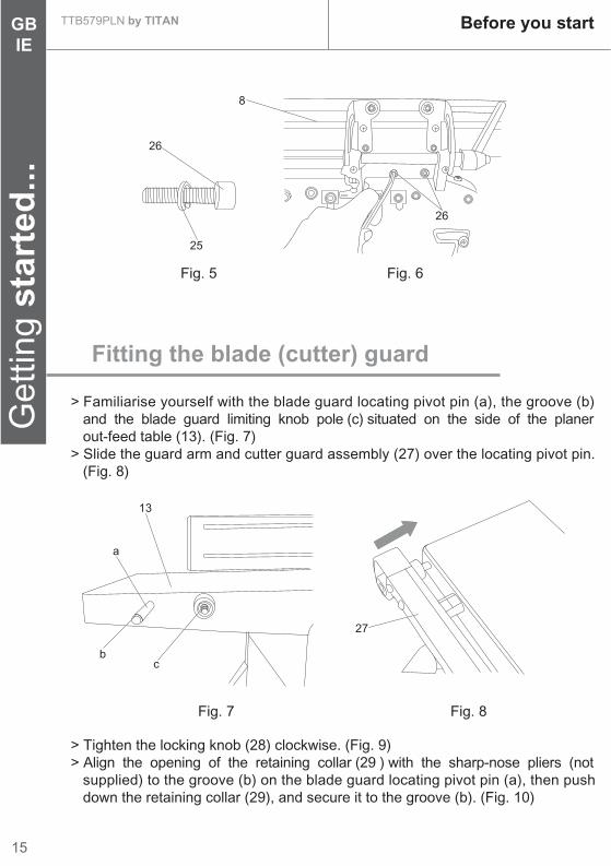
> Line up the 2 x mounting holes on the guide fence (8) with those situated on the out-feed table.> Fit a spring washer M6 (25) and a hex head screws M6 x 25mm (26) through both sets of holes and tighten with the 5mm hex key to secure. (Fig 5 & 6)
NOTE: Do not over-tighten the screws as this will cause un-wanteddamage to the aluminium outfeed table. Just tighten until thefence is secured.
Fig. 3 Fig. 4
24
Fig. 2Fig. 13
23
23
13
22
15
TTB579PLN by TITAN Before you startGBIE
Get
ting
star
ted
...
Fitting the blade (cutter) guard
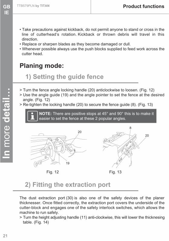
> Familiarise yourself with the blade guard locating pivot pin (a), the groove (b) and the blade guard limiting knob pole (c) situated on the side of the planer out-feed table (13). (Fig. 7)> Slide the guard arm and cutter guard assembly (27) over the locating pivot pin. (Fig. 8)
> Tighten the locking knob (28) clockwise. (Fig. 9)> Align the opening of the retaining collar (29 ) with the sharp-nose pliers (not supplied) to the groove (b) on the blade guard locating pivot pin (a), then push down the retaining collar (29), and secure it to the groove (b). (Fig. 10)
Fig. 6Fig. 5
Fig. 8Fig. 7
8
25
26
26
27
a
cb
13

Before you startTTB579PLN by TITAN
Get
ting
star
ted
...
GBIE
18
Fig. 11
Fig. 9 Fig. 10
Fitting the height adjusting handle
> Fit the height adjusting handle (11) over its shaft. (Fig. 11)
11
28
29
ba

19
In m
ore
det
ail…
GBIE
TTB579PLN by TITAN
In more detail…
20
28
36
39
40
Product functions
Care and maintenance
Trouble shooting
Recycling and disposal
EC declaration of conformity

Important: This 1500W jointer planer is intended specifically for planning and thicknessing operations on solid timber. When being thickened, thecontact surface of the work piece must be flat.If working with bigger or heavier work-pieces it is necessary to clamp the machinefirmly to its supporting bench or table. The machine is not suitable for operationoutdoors when raining or in any damp environment. Any other use beyond thisscope is considered as failing to comply with the machines intended purpose. Themanufacturer is not liable for any damage or injuries caused as a result of this;the risk is borne solely by the user.The ON / OFF switch (1) of machine is located on the left side below the yellowcover. To switch the machine on: Lift the yellow cover and press the green button“1”.To switch the machine off: Press the red button “0” or firmly close the cover.The switch can be locked to prevent the machine from being inadvertently switchedon by folding down the yellow cover.This machine is equipped with an overload switch (2) for motor running protection.Once the overload occurs, the machine will stop automatically. After a while, theoverload switch can be reset. Warning: Operation of any power tool can result in foreign objects being thrown into the eyes which can result in severe eye injury.Always wear safety goggles, it is also advisable to wear ear protection particularlyif using the planer for extended periods.For your own safety, read all of the safety instructions in this manual and adhereto all precautions before and during operation of the planer thicknesser.
Before each use:• Make sure all moving parts are free from interference.• Make sure blades are aligned and correctly attached to cutter-head (See maintenance section of this manual).• Do not plug in the jointer planer unless the switch is in “off’ position.• After turning the switch on, allow the cutter block to come to full speed before commencing the operation.• Keep hands clear of all moving parts.• Do not force the cut. Slowing or stalling the cutter will force the overload to cut in and will greatly reduce the life of the motor.• Use quality dry timber. Blades last longer and cuts are smoother with good quality wood.• Do not pull the workpiece back over the cutter block towards the infeed table.• Support the work-piece adequately at all times during operation; maintain control of the workpiece.
Product functionsTTB579PLN by TITAN
20
In m
ore
det
ail…
GBIE
21
TTB579PLN by TITAN Product functionsIn
mor
e d
etai
l…GBIE
1) Setting the guide fence
Planing mode:
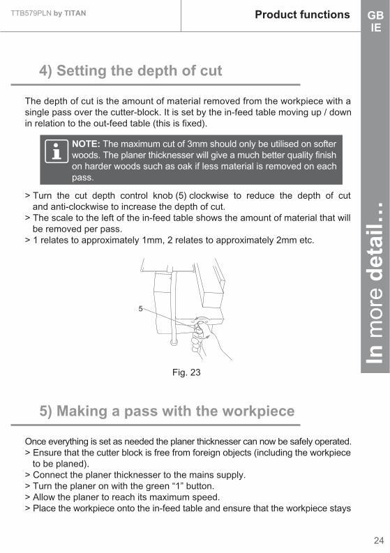
> Turn the fence angle locking handle (20) anticlockwise to loosen. (Fig. 12)> Use the angle guide (19) and the angle pointer to set the fence at the desired angle. (Fig. 12)> Re-tighten the locking handle (20) to secure the fence guide (8). (Fig. 13)
2) Fitting the extraction port
The dust extraction port (30) is also one of the safety devices of the planerthicknesser. Once fitted correctly, the extraction port covers the underside of thecutter-block and engages one of the safety interlock switches, which allows themachine to run safely.> Turn the height adjusting handle (11) anti-clockwise, this will lower the thicknesing table. (Fig. 14)
• Take precautions against kickback, do not permit anyone to stand or cross in the line of cutterhead’s rotation. Kickback or thrown debris will travel in this direction.• Replace or sharpen blades as they become damaged or dull.• Whenever possible always use the push blocks supplied to feed work across the cutter head.
NOTE: There are positive stops at 45° and 90° this is to make iteasier to set the fence at these 2 popular angles.
Fig. 12 Fig. 13
2020
8
19

Product functionsTTB579PLN by TITAN
22
In m
ore
det
ail…
GBIE
Caution: Do not secure the extraction port too tightly If too muchforce is applied to the height adjusting handle the extraction portwill go beyond its optimum position, the safety interlock switch willdisengage and the motor will not run.
Fig. 14 Fig. 15
Fig. 16 Fig. 18Fig. 17
> Continue turning the handle until the thicknesser table reaches its lowest point.> On the bottom of the thicknesser table there are 3 holes, these are the locating holes for the corresponding locating points on the extraction port assembly. (Fig. 15)> Make note of “tab d” as this is the point that engages the interlock switch (31) and allows the planer thicknesser to run safely. (Fig. 16 & 17)> Take care to ensure that this “tab” is located correctly whilst fitting the dust extraction port.> Hold the dust extraction port (30) assembly at approximately 45° and slide it into place onto the thicknesser bed. (Fig. 18)> Loosen the nut (32) with 10mm spanner supplied, then remove it and the flat washer M8 (33). (Fig. 16)> Ensure that the 3 locating points line up with the corresponding holes on the thicknesser bed and set the port flat against the bed.> Secure the extraction port by fitting the flat washer M8 (33) and the nut (32) onto the middle (threaded) locating point, then tighten the nut (32).> Turn the height adjusting handle (11) clockwise to raise the thicknesser bed. This will secure the extraction port in place as well as engaging the safety interlock switch.
d
3033
30
11
32
31

23
TTB579PLN by TITAN Product functionsIn
mor
e d
etai
l…GBIE
Fig. 19 Fig. 20
Fig. 21 Fig. 22
> Once fitted correctly, the extraction port should look as in Fig 19.> Finally, fit the extraction port adapter (7) by simply sliding it over the extraction port as in Fig 20.
Caution: When the machine is not in use the plug should beremoved from the mains socket and the blade guard (9) should beset so that it covers the whole of the cutter assembly so asto reduce the risk of injury.
3) Setting the blade guard
> Loosen the blade guard locking knob (10).> Pull back the blade guard (9).> Set the workpiece against the guide fence (8).> Slide the blade guard (9) towards the workpiece (leaving a small gap of a few millimetres).> Re-tighten the blade guard locking knob (10) to secure.
728
10
9
10
9
In m
ore
det
ail…
Product functionsTTB579PLN by TITAN
24
GBIE
Fig. 23
NOTE: The maximum cut of 3mm should only be utilised on softerwoods. The planer thicknesser will give a much better quality finishon harder woods such as oak if less material is removed on eachpass.
4) Setting the depth of cut
The depth of cut is the amount of material removed from the workpiece with asingle pass over the cutter-block. It is set by the in-feed table moving up / downin relation to the out-feed table (this is fixed).
5) Making a pass with the workpiece
Once everything is set as needed the planer thicknesser can now be safely operated.> Ensure that the cutter block is free from foreign objects (including the workpiece to be planed).> Connect the planer thicknesser to the mains supply.> Turn the planer on with the green “1” button.> Allow the planer to reach its maximum speed.> Place the workpiece onto the in-feed table and ensure that the workpiece stays
> Turn the cut depth control knob (5) clockwise to reduce the depth of cut and anti-clockwise to increase the depth of cut.> The scale to the left of the in-feed table shows the amount of material that will be removed per pass.> 1 relates to approximately 1mm, 2 relates to approximately 2mm etc.
5
25
TTB579PLN by TITAN Product functionsIn
mor
e d
etai
l…GBIE
parallel with the in-feed table for the whole pass.> Slowly push the workpiece forward (over the cutter-block). Caution: It is much safer (particularly when using a thin / small workpiece) to use the supplied push blocks (34).> Repeat these steps until the correct amount of material has been removed.
Fig. 24
Fig. 25 Fig. 26
NOTE: Keep firm and even pressure on the workpiece as it passesover the in-feed table and continue pushing forward until the backof the workpiece passes the cutter-block.
1) Setting the blade guard
Thicknesser mode:
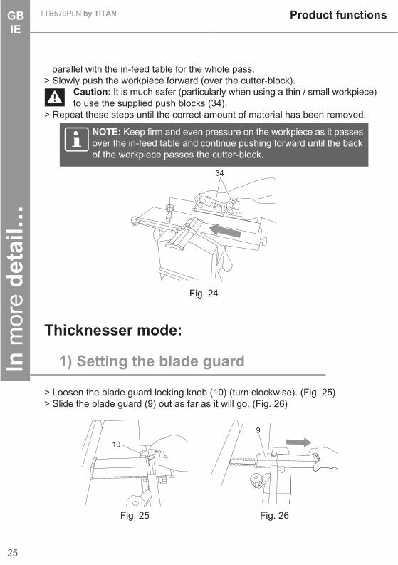
> Loosen the blade guard locking knob (10) (turn clockwise). (Fig. 25)> Slide the blade guard (9) out as far as it will go. (Fig. 26)
10
9
34
Product functionsTTB579PLN by TITAN
26
In m
ore
det
ail…
GBIE
Fig. 29 Fig. 30
Fig. 28
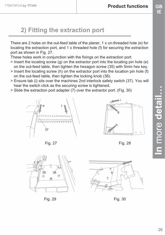
2) Fitting the extraction port
There are 2 holes on the out-feed table of the planer, 1 x un-threaded hole (e) forlocating the extraction port, and 1 x threaded hole (f) for securing the extractionport as shown in Fig. 27.These holes work in conjunction with the fixings on the extraction port.> Insert the locating screw (g) on the extractor port into the locating pin hole (e) on the out-feed table, then tighten the hexagon screw (35) with 5mm hex key.> Insert the locating screw (h) on the extractor port into the location pin hole (f) on the out-feed table, then tighten the locking knob (36).> Ensure tab (i) sits over the machines 2nd interlock safety switch (37). You will hear the switch click as the securing screw is tightened.> Slide the extraction port adapter (7) over the extractor port. (Fig. 30)
Fig. 27
e f
37
i
g
h
35 36
0 1 2 3
27
TTB579PLN by TITAN Product functionsIn
mor
e d
etai
l…GBIE
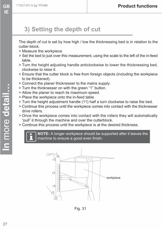
NOTE: A longer workpiece should be supported after it leaves themachine to ensure a good even finish.
Fig. 31
3) Setting the depth of cut
The depth of cut is set by how high / low the thicknessing bed is in relation to thecutter-block.> Measure the workpiece.> Set the bed to just over this measurement, using the scale to the left of the in-feed table.> Turn the height adjusting handle anticlockwise to lower the thicknessing bed, clockwise to raise it.> Ensure that the cutter block is free from foreign objects (including the workpiece to be thickened).> Connect the planer thicknesser to the mains supply.> Turn the thicknesser on with the green “1” button.> Allow the planer to reach its maximum speed.> Place the workpiece onto the in-feed table.> Turn the height adjustment handle (11) half a turn clockwise to raise the bed.> Continue this process until the workpiece comes into contact with the thicknesser drive rollers.> Once the workpiece comes into contact with the rollers they will automatically “pull” it through the machine and over the cutterblock.> Continue this process until the workpiece is at the desired thickness.
0
10
20
30
40
50
60
70
80
90
100
110
120
workpiece

Care and maintenanceTTB579PLN by TITAN
28
In m
ore
det
ail…
GBIE
> Check for damaged parts and repair or replace them as necessary.> Ensure all nuts and bolts etc are secure.> Ensure that all moving parts move freely and are not binding prior to starting the machine.> Remove adjusting keys and wrenches and check to see that keys and adjusting wrenches are removed from the tool before turning it on.
> Keep the product clean. Remove debris from it after each use and before storage.> Regular and proper cleaning will help ensure safe use and prolong the life of the product.> Inspect the product before each use for worn and damaged parts. Do not operate it if you find broken and worn parts.
The golden rules for care
Before each use
> Constantly check for abnormalities. Stop the operation immediately if something does not look or sound right and have the machine checked by a suitably qualified person.> Remove any buildup of chippings and pay particular attention around the base of the planer thicknesser, as build up there will prevent the cooling air from reaching the motor.
During use
Caution: Always ensure that the machine is turned off and thatthe plug is removed from the mains supply before carrying out anyrepairs or maintenance.
WARNING! Only perform repairs and maintenance work accordingto these instructions! All further works must be performed by aqualified specialist!
29
TTB579PLN by TITAN Care and maintenanceIn
mor
e d
etai
l…GBIE
Caution: Always wear a dust mask and eye protection when using dry air.
> Remove all chippings etc from the planer thicknesser.> Remove all chippings etc from around the air inlets of the motor. If these become blocked the motor will become too hot and its service life will be greatly reduce.> Wrap the mains lead carefully around the cable clips. This will reduce the risk of tripping and / or damage to the cable.
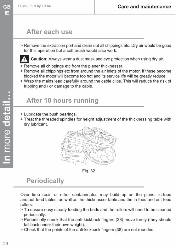
After 10 hours running
> Lubricate the bush bearings.> Treat the threaded spindles for height adjustment of the thicknessing table with dry lubricant.
Periodically
Over time resin or other contaminates may build up on the planer in-feedand out-feed tables, as well as the thicknesser table and the in-feed and out-feedrollers.> To ensure easy steady feeding the beds and the rollers will need to be cleaned periodically.> Periodically check that the anti-kickback fingers (38) move freely (they should fall back under their own weight).> Check that the points of the anti-kickback fingers (38) are not rounded.
After each use
> Remove the extraction port and clean out all chippings etc. Dry air would be good for this operation but a soft brush would also work.
Fig. 32

Care and maintenanceTTB579PLN by TITAN
30
In m
ore
det
ail…
GBIE
Fig. 33
Fig. 34 Fig. 35 Fig. 36
The positive stops at 90° and 45° are set at the factory to ensure accuracy, howeverover time they may need to be reset.> Loosen the fence angle lock handle (20).> Sit a 90° square firmly on the planer table.> Set the guide fence against the square, this will give an angle of 90° between the bed and the fence.> Loosen the lock nut (j).> Tighten / loosen the angle locking bolt until it sits against the angle stop on the angle guide (19), whilst ensuring that the 90° angle is kept.> Re-tighten the lock nut to hold the bolt securely in place.> Loosen the angle pointer screw (k) and set the angle pointer so that it reads 90°.> To set the 45° positive stop, set the guide fence so that the angle pointer is at 45°.> Loosen the 45° lock nut (l).> Tighten / loosen the angle locking bolt until it sits against the 45° stop on the angle guide.> Re-tighten the locking nut to secure.
Setting the positive stops on theguide fence
38
18j
l
17
16
k20
19

31
TTB579PLN by TITAN Care and maintenanceIn
mor
e d
etai
l…GBIE
Caution: Not to touch the tips of the blades as it would cause hurtsto you.
Caution: Take care not to lose the blade tensioning springs fromthe cutter-block after the blade assembly has been removed.
NOTE: Remember the correct orientation of the blade to ensurethat the new one can be fitted correctly.
Fig. 37 Fig. 39Fig. 38
Replacing the cutter blades:
> Remove the guide fence.> Loosen the blade guard locking knob anticlockwise, then slide the blade guard away from the cutterblock as far as it will go.> Turn the cutter-block so that one of the blades is exposed in the gap between the in-feed (6) and out-feed (13) tables.> Turn the five blade tensioning screws (39) anticlockwise with 10mm spanner to loosen. (Fig. 37)> Once all five screws have been loosened, the blade complete with the blade clamping device can be easily removed. (Fig. 38)
> Whilst removed, all parts (including the cutterblock) should be thoroughly cleaned.
1) Removing the blade
6
13
39
Care and maintenanceTTB579PLN by TITAN
32
In m
ore
det
ail…
GBIE
Caution: This operation should only be carried out by a suitablyqualified person.
NOTE: Once this operation is complete, ensure that the cutter-block turns freely by hand before re-connecting the machine to themains supply. Replace all safety guards immediately aftercompleting this operation.
Fig. 42Fig. 41Fig. 40
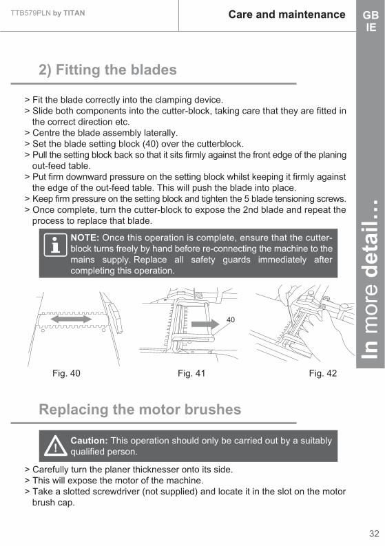
> Fit the blade correctly into the clamping device.> Slide both components into the cutter-block, taking care that they are fitted in the correct direction etc.> Centre the blade assembly laterally.> Set the blade setting block (40) over the cutterblock.> Pull the setting block back so that it sits firmly against the front edge of the planing out-feed table.> Put firm downward pressure on the setting block whilst keeping it firmly against the edge of the out-feed table. This will push the blade into place.> Keep firm pressure on the setting block and tighten the 5 blade tensioning screws.> Once complete, turn the cutter-block to expose the 2nd blade and repeat the process to replace that blade.
2) Fitting the blades
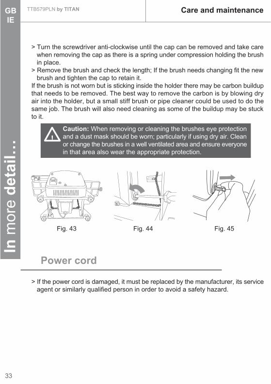
> Carefully turn the planer thicknesser onto its side.> This will expose the motor of the machine.> Take a slotted screwdriver (not supplied) and locate it in the slot on the motor brush cap.
Replacing the motor brushes
40
33
TTB579PLN by TITAN Care and maintenanceIn
mor
e d
etai
l…GBIE
Caution: When removing or cleaning the brushes eye protectionand a dust mask should be worn; particularly if using dry air. Cleanor change the brushes in a well ventilated area and ensure everyonein that area also wear the appropriate protection.
Power cord
> If the power cord is damaged, it must be replaced by the manufacturer, its service agent or similarly qualified person in order to avoid a safety hazard.
Fig. 43 Fig. 44
> Turn the screwdriver anti-clockwise until the cap can be removed and take care when removing the cap as there is a spring under compression holding the brush in place.> Remove the brush and check the length; If the brush needs changing fit the new brush and tighten the cap to retain it.If the brush is not worn but is sticking inside the holder there may be carbon buildupthat needs to be removed. The best way to remove the carbon is by blowing dryair into the holder, but a small stiff brush or pipe cleaner could be used to do thesame job. The brush will also need cleaning as some of the buildup may be stuckto it.
Fig. 45
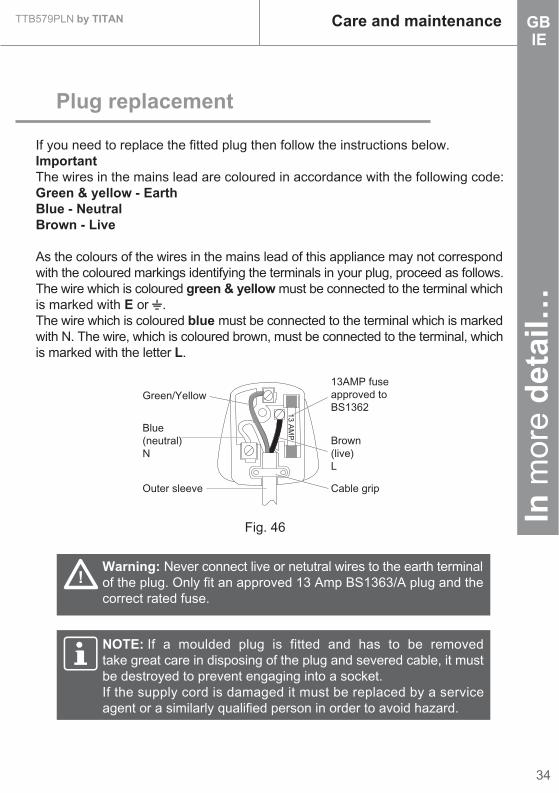
Fig. 46
Warning: Never connect live or netutral wires to the earth terminalof the plug. Only fit an approved 13 Amp BS1363/A plug and thecorrect rated fuse.
Green/Yellow13AMP fuseapproved toBS1362
Brown(live)L
Cable grip
Blue(neutral)N
Outer sleeve
13 AM
P
If you need to replace the fitted plug then follow the instructions below.ImportantThe wires in the mains lead are coloured in accordance with the following code:Green & yellow - EarthBlue - NeutralBrown - Live
As the colours of the wires in the mains lead of this appliance may not correspondwith the coloured markings identifying the terminals in your plug, proceed as follows.The wire which is coloured green & yellow must be connected to the terminal whichis marked with E or .The wire which is coloured blue must be connected to the terminal which is markedwith N. The wire, which is coloured brown, must be connected to the terminal, whichis marked with the letter L.
Plug replacement
NOTE: If a moulded plug is fitted and has to be removedtake great care in disposing of the plug and severed cable, it mustbe destroyed to prevent engaging into a socket.If the supply cord is damaged it must be replaced by a serviceagent or a similarly qualified person in order to avoid hazard.
Care and maintenanceTTB579PLN by TITAN
34
In m
ore
det
ail…
GBIE
TTB579PLN by TITAN Care and maintenanceIn
mor
e d
etai
l…GBIE
35
Repair
> This product does not contain any parts that can be repaired by the consumer. Contact a qualified specialist to have it checked and repaired.
Storage
> Clean the product as described above.> Store the product and its accessories in a dry, frost-free place.> Always store the product in place that is inaccessible to children. The ideal storage temperature is between 10 and 30°C.> We recommend using the original package for storage or covering the product with a suitable cloth to protect it against dust.
Transportation
> Switch the product off and disconnect it from power supply before transporting it anywhere.> Protect the product from any heavy impact or strong vibrations which may occur during transportation in vehicles.> Secure the product to prevent it from slipping or failing over.

Trouble shootingTTB579PLN by TITAN
36
In m
ore
det
ail…
GBIE
WARNING! Only perform the steps described within theseinstructions! All further inspection, maintenance and repair workmust be performed by an authorised service centre or a similarlyqualified specialist if you cannot solve the problem yourself!
Caution: Troubleshooting could lead to an increased risk to theoperator due to the fact that safety guards / covers may have tobe removed. It is therefore particularly important that all themeasures necessary for safe working are taken.
Suspected malfunctions are often due to causes that the users can fix themselves.Therefore check the product using this section.In most cases the problem can be solved quickly.
Trouble shooting
Problem Possible cause Solution1. Machine will not run
1.1 No mains voltage1.2 Fuse blown
1.3 Overload switch has cut in
1.4 Faulty On/Off switch
1.5 Carbon brushes worn
1.6 Faulty motor
1.7 Damaged mains lead
1.8 Safety interlock switch is not correctly engaged
1.1 Check the supply1.2 Check the fuse and replace if necessary1.3 Allow the machine to cool and reset the switch1.4 Check and replace if necessary1.5 Check and replace if necessary1.6 Check and replace if necessary1.7 Check and replace if necessary1.8 Check that the extraction port is correctly seated
2. Speed drops whilst the machine is under load
2.1 Cutting depth is too great2.2 Feed rate is too fast2.3 Dull cutter blades
2.1 Reduce the cutting depth2.2 Reduce the feed rate2.3 Replace / sharpen the cutter blades

37
TTB579PLN by TITAN Trouble shootingIn
mor
e d
etai
l…GBIE
Problem Possible cause Solution3. The motor cuts out whilst under no load
3.1 Mains failure3.2 Motor has exceeded its duty cycle
3.3 Faulty motor
3.4 Faulty On/Off switch
3.1 Check the supply3.2 Allow the motor to cool and reset the overload3.3 Check and replace if necessary3.4 Check and replace if necessary
4. The motor cuts out whilst under load
4.1 Motor has exceeded its duty cycle and the overload has cut in4.2 Cutting depth is too great so the overload has cut in
4.3 Feed rate is too fast so the overload has cut in
4.4 Dull cutter blades so the overload has cut in
4.1 Allow the motor to cool and reset the overload4.2 Allow the motor to cool and reset the overload. Reduce the cutting depth4.3 Allow the motor to cool and reset the overload; Reduce the feed rate4.4 Replace or sharpen the blades, allow the motor to cool and reset the overload
5. Poor finish on workpiece
5.1 Dull or damaged blades5.2 Uneven feed rate
5.3 Feed rate too fast
5.1 Replace or sharpen the blades5.2 Ensure constant pressure on the workpiece whilst planing5.3 Reduce the speed of feed
6. Extraction port becomes blocked whilst thicknessing (without external extraction)
6.1 Cutting depth too great6.2 Wood is too damp
6.1 Reduce the cutting depth6.2 Allow the wood to dry

38
Trouble shootingTTB579PLN by TITAN
In m
ore
det
ail…
GBIE
Problem Possible cause Solution7. Extraction port becomes blocked whilst planing (without external extraction)
7.1 Cutting depth too great7.2 Feed rate too fast7.3 Wood is too damp
7.1 Reduce the cutting depth7.2 Reduce the feed rate7.3 Allow the wood to dry

Recycling and disposal
> Waste electrical products should not be disposed of with household waste. Please recycle where facilities exist. Check with your Local Authority or local store for recycling advice.
39
TTB579PLN by TITAN Recycling and disposalIn
mor
e d
etai
l…GBIE

1500W JOINTER PLANER TTB342BTE
Signature:_________________
Authorised Signatory and technical file holderDate : 25/09/2013
Name / title: Peter Harries / Quality ManagerTitan Power Tools (UK) Ltd. Trade House, Mead Avenue, BA22 8RT
Declaration of Conformity
We, ImporterTitan Power Tools (UK) Ltd
Trade House, Mead Avenue, BA22 8RT
Declare that the product:Designation: 1500W jointer planer
Model: TTB342BTE
Complies with the following Directives:2004/108/EC Electromagnetic Compatibility Directive
2006/42/EC Machinery Directive2006/95/EC Low Voltage Directive
2011/65/EU Restrictions of the Use of Certain Hazardous Substances in Electrical and ElectronicEquipment
2002/96/EC and 2003/108/EC Waste Electrical and Electronic Equipment (WEEE)
Standards and technical specifications referred to:
EN 61029-1/A11:2010EN 61029-2-3:2011
EN 55014-1/A1:2009EN 55014-2/A2:2008
EN 61000-3-2/A2:2009EN 61000-3-11:2000

Titan Power Tools (UK) LtdTrade House, Mead Avenue,BA22 8RT
GB


