1. Remove SCU-1800 from box and carefullyremove all packaging material.
2. Mount SCU-1800 chassis in rack using thefour holes provided on the front panel.
3. Connect grounding strap of chassis to EarthGrounding termina on screws on the rearpanel of the SCU-1800.
4. Remove the protec ve cover over the DCpower lugs on the rear panel of theSCU-1800.
a. If using an exis ng -48VDC powersupply, double-check that power isturned off. Connect the -48V and RTNleads from the power supply to theappropriate power lugs on the rearpanel of the SCU-1800.
b. If using the VIAVI-supplied op onal ACpower adapter, connect the adapterterminals to the appropriate SCU-1800power lugs. Black wire goes to -48VDClug, white wire goes to RTN lug.
5. Replace the clear plas c cover over thepower lugs.
6. Connect jumpers from the RF source to theappropriate receive ports on the rear of theSCU-1800 as shown in conection diagram.
Connect the RF OUT port as shownPort 1 on the receive port is the only ac ve reverse sweep receive port on theSCU-1800-FWD-REV-1P andSCU-1800-MU-REV-1P.
Ports 1 through 16 are all ac ve reversesweep ports on the SCU-1800-FWD-REV-16and the SCU-1800- MU-REV-16P.
The reverse feeds for reverse sweepingshould be connected appropriately to one ofthe receive ports.
Receive Ports
The return levels should ideally be received at 0dBmV for op mal performance but can work over the range of +/- 10dBmV depending on the overall combined noise floor. There must be > 20dB SNR on the return telemetry to be properly received.
NOTE:The SCU-1800-FWD-REV-1P and SCU-1800- FWD-REV-16P do not connect the same as the SDA- 5500 for forward sweep. The forward levels are not directly measured by the SCU-1800. The stability and accuracy of the transmi er alleviated the need to be locally measured.
CAUTION:DO NOT connect the forward path signals to any of the 16 receive ports.
7. Connect Ethernet feed to RJ45 connectorsocket on the rear of the SCU-1800.
8. Apply power to the SCU-1800. Once power isapplied to the SCU-1800 the LCD will display:
LCD Display Screen and Keypad
LCD Display at Start-Up
NOTE:The actual IP address that appears may be different than shown below.
9. A er approximately 20 seconds the LCD willdisplay the IP address of the unit:
IP Address of SCU-1800
The following figure explains what each line and/or symbol on the LCD is showing.
Explana on of LCD Fields
There are five different fields that may be viewed on the LCD by using either the up or down arrow keys to scroll. Three may be edited, the other two which are for informa onal purposes only.
Shown below are the three fields which may be edited (all field values may be different from what is shown).
IP Address of the SCU-1800
Subnet Mask of the SCU-1800
Default Gateway of the SCU-1800
The following figures show the remaining two fields that are informa onal only and cannot be edited from the SCU-1800 front panel. The horizontal line immediately below the down arrow is not present in these two fields indica ng that they cannot be edited via the front panel.
Physical (MAC) Address of the SCU-1800 Ethernet Adapter
CAUTION:Before se ng any IP address informa on in the SCU-1800, please confirm with your network administrator that the IP addresses you have are valid for your network configura on and will not cause any conflicts on your local area network.
10. To set the IP address of the SCU-1800, usethe up or down arrow keys to scroll to the IPaddress field on the LCD and press the"Enter" bu on. The horizontal line thatindicates that this is a field that may beedited drops to the bo om of the first digit inthe IP address field and becomes a cursorindica ng that the SCU is now in "editmode".
IP Address in Edit Mode
SCU-1800 Getting Started Guide
!
!
!
SYSTEM REQUIREMENTS
• SCU-1800 Chassis• 48V DC Power Supply (+/- 5%, 1A max
current)• 10/100 BaseT Ethernet connec on with sta c
IP
CAUTION:Be sure that power is off on the -48V DC power source before connec ng or disconnec ng power leads to the SCU-1800.
GETTING TO KNOW THE SCU-1800
The front panel consists of:The power bu on
The 4 cursor or arrow keys
The "Enter" or "Accept" bu on
The "Exit or "Cancel" bu on
The informa on LCD
SETUP OF FORWARD SWEEP AND TELEMETRY ON THE SCU-1800-FWD-REV-1P AND SCU-1800-FWD-REV-16P
The Transmit mode of the SCU will only work with DSAM-6300, ONX-630’s or SDA-5000 field units that are in SDA compa ble mode.
Forward Telemetry Frequency must be in a vacant spectrum and at least 500 kHz from any other carrier. It must also be within the bandwidth of the downstream spectrum. This is an FSK carrier and approximately 500 kHz wide. The factory default is 51 MHz for forward Sweep (like the SDA-5500 transmi er,) 52 MHz on reverse mul user sweep receiver (like SDA-5510), and 53 MHz on the PathTrak™ HSM (a common Viavi element also typically located with the SCU-1800 and SDA sweep gear).
NOTE:If diplex filters in the ac ves have a sharp rolloff, it is advisable to move the telemetry to a frequency that is more reliable. The loca on and level of the telemetry may cause its second harmonic to interfere with exis ng channels if not op mally adjusted.
Forward Telemetry Level determines the level of the telemetry signal. This should be set 10 dB below the video reference level. The telemetry level is adjustable from 20 to 50 dBmV in 1 dB increments. The max is 50 dBmV; Forward Sweep Inser on Level is the level at which sweep inser on points will be inserted; 50 dBmV is the max.
Sweep points should be 14 to 16 dB below the video reference level. Sweep points fall on the video and/or audio frequency of unused channels by default, but can be moved.
Ini ally set the Telemetry and Sweep Inser on levels to the minimum of 20 dBmV each. Change the sweep inser on level un l the sweep inser on points are 14 to 16 dB below the closest visual carrier. You can use a spectrum analyzer such as the VSE-1100 or the ONX-630 to view this. Once the sweep is set correctly, change the telemetry level to 4 dB above the Sweep Inser on level.
Enable Reverse Sweep allows reverse sweep to operate. If disabled, the forward sweep will be faster.
SETUP OF REVERSE SWEEP ON THE SCU-1800-FWD-REV-1P AND SCU-1800-FWD-REV-16PSCU-1800-REV-MU-1P AND SCU-1800-REV-MU-16P
Reverse Telemetry Frequency is set up on the SCU-1800 and not on the field unit.
NOTE: Be sure to select a reliable frequency void of interference in the most stable part of the passband, not in the roll-off or below 15 MHz.
Reverse Channel Plans are built and/or edited for the upstream direc on. The reverse channel plan must be set-up on the unit that is to receive the sweep points from the upstream receiver (either the SCU-1800-FWD-REV-1P/16P or the SCU-1800-REV-MU-1P/16P).
The reverse sweep plan will be communicated automa cally to the field units via the forward telemetry.
SETUP OF FORWARD TELEMETRY ON THE MULT-USER REVERSE SWEEP UNITS SCU-1800-REV-MU-1P AND SCU-1800-REV-MU-16P
The Mul User units only units u lize a forward telemetry to communicate to the field instruments to transmit sweep results and to instruct the field unit where and when to transmit sweep pulses. Follow the same guidelines for forward telemetry setup as described in the forward sweep setup.
SCU-1800 UNPACKING AND SETUP (cont’d)
11. Use the up or down arrow keys to set thefirst number of the first IP address octet(range blank thru 2). If the first octet is lessthan 100, scroll un l the digit is blank. Oncethe first number is set, use the right arrowkey to move the cursor to the secondnumber of the first IP address octet.
IP Address in Edit Mode (1st Octet)
12. Use the up or down arrow keys to set thisnumber to the proper value (range 0 thru9). Once this number is set, use the rightarrow to move the cursor to the next digit.
13. Follow the same process un l the correct IPaddress shows on the display and thenpress "Enter". This will save the addressinforma on and place the unit back innormal opera on mode.
14. Now, press the down arrow to go to thesubnet mask field and repeat the processused to set the IP address. When thesubnet mask is correct, press the downarrow and repeat once more for the defaultgateway.
15. There is no need to reboot the SCU-1800.Once you press the "Enter" bu on at theend of each field, the address is set andapplied. When all the addresses are set,verify network connec vity from a PC tothe SCU-1800.
16. Using a PC connected to the same network,open up a web browser and type in the IPaddress of the SCU-1800 (e.g.h p://10.11.15.55). You may also access itby adding port 8000 to the address (e.g.h p://10.11.15.55:8000).
The SCU-1800 is login protected. The ini al login informa on is: user name: scuadmin password: scuadmin
1. Re rez le SCU-1800 de la boîte et re rez délicatement tous les emballages.
2. Montez le châssis du SCU-1800 en rack à l’aide des quatre trous fournis sur le panneau avant.
3. Fixez la courroie du châssis aux vis d’extrémité de mise à la terre sur le panneau arrière du SCU-1800.
4. Re rez la protec on des bornes d’alimenta on sur le panneau arrière du SCU-1800.
a. Si vous u lisez une alimenta on -48 V c.c. existante, vérifiez bien que l’alimenta on est coupée. Branchez les fils -48 V et RNT de l’alimenta on aux bornes appropriées sur le panneau arrière du SCU-1800.
b. Si vous u lisez l’adaptateur c.a. en op on fourni par VIAVI, branchez les bornes de l’adaptateur aux bornes d’alimenta on prévues du SCU-1800. Le fil noir va sur la borne -48 V c.c., le fil blanc va sur la borne RTN.
5. Remplacez la protec on en plas que transparent sur les bornes d’alimenta on.
6. Branchez les cavaliers de la source RF aux ports de récep on adéquats à l’arrière du SCU-1800, tel qu’illustré dans le schéma de connexion.
Branchez le port RF OUT comme illustré. Le port 1 sur le port de récep on est le seul port de récep on de balayage arrière ac f sur les unités SCU-1800-FWD-REV-1P et SCU-1800-MU-REV-1P.
Les ports 1 à 16 sont tous les ports de balayage arrière ac fs sur les unités SCU-1800-FWD-REV-16 et SCU-1800- MU-REV-16P.
Les flux de recul pour le balayage arrière doivent être correctement branchés à l’un des ports de récep on.
Ports de récep on
Les niveaux de retour doivent être reçus à 0 dBmV pour avoir des performances op males, mais peuvent fonc onner sur la plage +/- 10 dBmV en fonc on du niveau de bruit combiné total. Le rapport signal/bruit doit être supérieur à 20 dB sur la télémétrie de retour pour que la récep on soit bonne.
REMARQUE :Les SCU-1800-FWD-REV-1P et SCU-1800- FWD-REV-16P ne se connectent pas comme le SDA-5500 pour le balayage avant. Les niveaux avant ne sont pas directement mesurés par le SCU-1800. La stabilité et l’exac tude du transme eur ont a énué la nécessité de réaliser une mesure locale.MISE EN GARDE : NE branchez PAS les signaux du chemin avant à l’un des 16 ports de récep on.
7. Branchez le flux Ethernet au connecteur RJ45 à l’arrière du SCU-1800.
8. Me ez le SCU-1800 sous tension. Cela fait, l’écran LCD affichera :
Écran LCD et clavier
Écran LCD au démarrage
REMARQUE :L’adresse IP réelle qui apparaît peut être différente de celle affichée ci-dessous.
9. Au bout d’environ 20 secondes, l’écran LCD affichera l’adresse IP de l’unité :
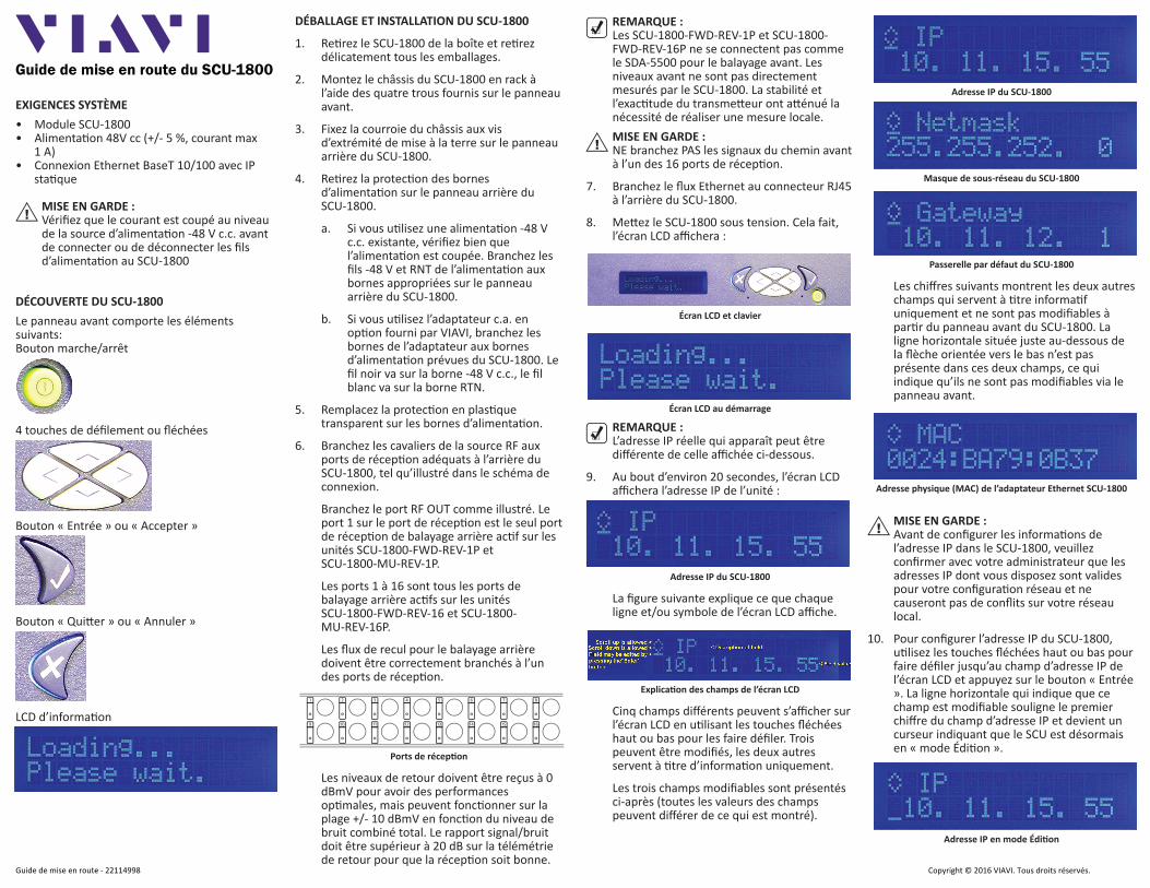
Adresse IP du SCU-1800
La figure suivante explique ce que chaque ligne et/ou symbole de l’écran LCD affiche.
Explica on des champs de l’écran LCD
Cinq champs différents peuvent s’afficher sur l’écran LCD en u lisant les touches fléchées haut ou bas pour les faire défiler. Trois peuvent être modifiés, les deux autres servent à tre d’informa on uniquement.
Les trois champs modifiables sont présentés ci-après (toutes les valeurs des champs peuvent différer de ce qui est montré).
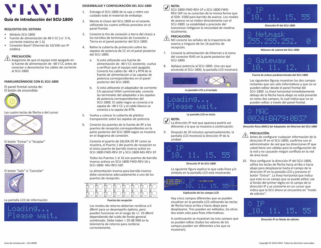
Adresse IP du SCU-1800
Masque de sous-réseau du SCU-1800
Passerelle par défaut du SCU-1800
Les chiffres suivants montrent les deux autres champs qui servent à tre informa f uniquement et ne sont pas modifiables à par r du panneau avant du SCU-1800. La ligne horizontale située juste au-dessous de la flèche orientée vers le bas n’est pas présente dans ces deux champs, ce qui indique qu’ils ne sont pas modifiables via le panneau avant.
Adresse physique (MAC) de l’adaptateur Ethernet SCU-1800
MISE EN GARDE :Avant de configurer les informa ons de l’adresse IP dans le SCU-1800, veuillez confirmer avec votre administrateur que les adresses IP dont vous disposez sont valides pour votre configura on réseau et ne causeront pas de conflits sur votre réseau local.
10. Pour configurer l’adresse IP du SCU-1800, u lisez les touches fléchées haut ou bas pour faire défiler jusqu’au champ d’adresse IP de l’écran LCD et appuyez sur le bouton « Entrée ». La ligne horizontale qui indique que ce champ est modifiable souligne le premier chiffre du champ d’adresse IP et devient un curseur indiquant que le SCU est désormais en « mode Édi on ».
Adresse IP en mode Édi on
Guide de mise en route du SCU-1800
!
!
!
EXIGENCES SYSTÈME• Module SCU-1800• Alimenta on 48V cc (+/- 5 %, courant max
1 A)• Connexion Ethernet BaseT 10/100 avec IP
sta que
MISE EN GARDE :Vérifiez que le courant est coupé au niveau de la source d’alimenta on -48 V c.c. avant de connecter ou de déconnecter les fils d’alimenta on au SCU-1800
DÉCOUVERTE DU SCU-1800Le panneau avant comporte les éléments suivants:Bouton marche/arrêt
4 touches de défilement ou fléchées
Bouton « Entrée » ou « Accepter »
Bouton « Qui er » ou « Annuler »
LCD d’informa on
Transme eur op que
Coupleuravant
Nœud
Nœud
Récepteur op que
Combinateurarrière
Sor e RF
Panneau arrière du SCU-1800
Récepteurop que
Usine extérieureTête de réseau/concentrateur
Récepteurop que
Nœud
Combinateuravant
TX
Transme eur op que
Transme eur op que
Le SCU-1800 est protégé par un accès avec iden fiant. Les iden fiants ini aux sont :nom d’u lisateur : scuadminmot de passe : scuadmin
CONFIGURATION DU BALAYAGE AVANT ET DE LA TÉLÉMÉTRIE SUR LES SCU-1800-FWD-REV-1P ET SCU-1800-FWD-REV-16PLe mode Transmission du SCU fonc onnera uniquement avec les unités sur site DSAM-6300, ONX-630 ou SDA-5000 qui sont en mode de compa bilité SDA
La fréquence de la télémétrie avant doit être comprise dans un spectre libéré et à au moins 500 kHz pour tout autre porteur. Elle doit également être comprise dans la bande passante du spectre en aval. Il s’agit d’un signal FSK et la bande passante est d’environ 500 kHz. La valeur d’usine par défaut est de 51 MHz pour le balayage avant (comme le transme eur SDA-5500), de 52 MHz sur le récepteur de balayage arrière mul -u lisateurs (comme le SDA-5510 et de 53 MHz sur le module HSM PathTrak™ (un élément Viavi courant aussi généralement présent sur le SCU-1800 et le système de balayage SDA).
REMARQUE : Si les filtres duplex sur les ports ac fs ont un filtre éliminatoire précis, il est conseillé de configurer la télémétrie à une fréquence plus fiable. L’emplacement et le niveau de la télémétrie peuvent entraîner des interférenc-es entre sa seconde harmonique et les canaux existants si les réglages ne sont pas op maux.
Le niveau de télémétrie avant détermine le niveau de signal de la télémétrie. Il doit être configuré à 10 dB sous le niveau de référence vidéo. Le niveau de télémétrie est ajustable de 20 à 50 dBmV par incrément de 1 dB. Le niveau d’inser on de balayage avant est le niveau auquel les points d’inser on du balayage seront insérés : le maximum est de 50 dBmV.
Les points de balayage doivent être configurés à de 14 à 16 dB sous le niveau de référence vidéo. Les points de balayage sont compris dans la fréquence vidéo ou audio des canaux inu lisés par défaut, mais peuvent être déplacés.
Dans un premier temps, configurez les niveaux de télémétrie et d’inser on de balayage sur un
minimum de 20 dBmV chacun. Modifiez le niveau d’inser on de balayage jusqu’à ce que les points d’inser on de balayage soient de 14 à 16 dB inférieurs au porteur visuel le plus proche. Vous pouvez u liser un analyseur de spectre tel que le VSE-1100 ou ONX-630 pour afficher cela. Une fois le balayage configuré correctement, modifiez le niveau de télémétrie sur 4 dB de plus que le niveau d’inser on du balayage.
La fonc on Ac ver le balayage arrière permet au balayage inversé de fonc onner. Si elle est désac vée, le balayage avant sera plus rapide.
CONFIGURATION DE LA TÉLÉMÉTRIE AVANT SUR LES UNITÉS DE BALAYAGE ARRIÈRE MULTI-UTILI-SATEURS SCU-1800-REV-MU-1P ET SCU-1800-REV-MU-16PLes unités mul u lisateurs u lisent une télémétrie avant pour dire aux instruments sur site de transme re les résultats du balayage et indiquer à l’unité sur site où et quand transme re les impulsions du balayage.
Suivez les mêmes direc ves pour configurer la télémétrie avant, tel que décrit dans la configura on du balayage avant.
CONFIGURATION DU BALAYAGE ARRIÈRE SUR LE SCU-1800-FWD-REV-1P ET SCU-1800-FWD-REV-16P, SCU-1800-REV-MU-1P ET SCU-1800-REV-MU-16PLa fréquence de la télémétrie arrière est configurée sur le SCU-1800 et non sur l’unité sur site.
REMARQUE : Assurez-vous de choisir une fréquence fiable sans interférence dans la par e la plus stable de la bande passante, pas dans le filtre éliminatoire ou en dessous de 15 MHz.
Les plans de canaux arrière sont établis et/ou modifiés aux fins de la direc on en aval. Le plan de canaux arrière peut être configuré sur l’unité qui va recevoir les points de balayage du récepteur en aval (soit le SCU-1800-FWD-REV-1P/16P, soit le SCU-1800-REV-MU-1P/16P).
Le plan de balayage arrière sera communiqué automa quement aux unités sur site via la télémétrie avant.
DÉBALLAGE ET INSTALLATION DU SCU-1800 (suite)
11. U lisez les touches fléchées haut ou bas pour définir le premier numéro du premier octet de l’adresse IP (plage vide à 2). Si le premier octet est inférieur à 100, faites défiler jusqu’à ce que le chiffre soit vide. Une fois le premier numéro défini, u lisez la touche fléchée droite pour passer le curseur au deuxième numéro du premier octet de l’adresse IP.
Adresse IP en mode Édi on (1er octet)
12. U lisez les touches fléchées haut ou bas pour configurer ce numéro sur la valeur appropriée (plage de 0 à 9). Une fois ce numéro configuré, u lisez la flèche droite pour passer le curseur au chiffre suivant.
13. Suivez le même processus jusqu’à ce que la bonne adresse IP s’affiche sur l’écran, puis appuyez sur « Entrée ». Cela entraînera l’enregistrement des informa ons de l’adresse et reme ra l’unité en mode de fonc onnement normal.
14. Appuyez maintenant sur la flèche vers le bas pour accéder au champ du masque de sous-réseau et répétez le processus u lisé pour configurer l’adresse IP. Lorsque le masque de sous-réseau est correct, appuyez sur la flèche vers le bas et répétez à nouveau le processus pour la passerelle par défaut.
15. Il est inu le de redémarrer le SCU-1800. Après avoir appuyé sur le bouton « Entrée » à la fin de chaque champ, l’adresse est définie et appliquée. Lorsque toutes les adresses sont configurées, vérifiez la connec vité réseau d’un PC au SCU-1800.
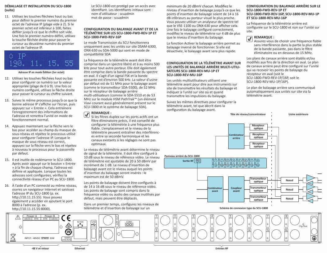
16. À l’aide d’un PC connecté au même réseau, ouvrez un navigateur Internet et saisissez l’adresse IP du SCU-1800 (p. ex. h p://10.11.15.55). Vous pouvez également y accéder en ajoutant le port 8000 à l’adresse (p. ex. h p://10.11.15.55:8000). Schéma de connexion type du SCU-1800
1. Extraiga el SCU-1800 de la caja y re re con cuidado todo el material de embalaje.
2. Monte el chasis del SCU-1800 en el estante u lizando los cuatro orificios provistos en el panel frontal.
3. Conecte la ra de conexión a erra del chasis a los tornillos de terminación de Conexión a Tierra en el panel posterior del SCU-1800.
4. Re re la cubierta de protección sobre las zapatas de potencia de CC en el panel posterior del SCU-1800.
a. Si está u lizando una fuente de alimentación de -48 V CC existente, vuelva a verificar que el equipo esté apagado. Conecte los cables de -48 V y RTN de la fuente de alimentación a las zapatas de potencia correspondientes en el panel posterior del SCU-1800.
b. Si está u lizando el adaptador de corriente CA opcional VIAVI suministrado, conecte las terminales del adaptador a las zapatas de potencia correspondientes del SCU-1800. El cable negro se conecta a la zapata de -48 V CC y el cable blanco se conecta a la zapata de RTN.
5. Vuelva a colocar la cubierta de plás co transparente sobre las zapatas de potencia.
6. Conecte los puentes de la fuente de RF a los puertos de recepción correspondientes en la parte posterior del SCU-1800 según se muestra en el diagrama de conexión.
Conecte el puerto de SALIDA DE RF como se muestra, el Puerto 1 del puerto de recepción es el único puerto de barrido inverso ac vo en SCU-1800-FWD-REV-1P y SCU-1800-MU-REV-1P.
Todos los Puertos 1 al 16 son puertos de barrido inverso ac vos en SCU-1800-FWD-REV-16 y SCU-1800- MU-REV-16P.
La alimentación inversa para barrido inverso debe conectarse adecuadamente a uno de los puertos de recepción.
Puertos de recepción
Los niveles de retorno deberían recibirse a 0 dBmV para un desempeño óp mo, pero pueden funcionar en el rango de +/- 10 dBmV dependiendo del ruido de fondo general combinado. Debe haber > 20 dB SNR en la telemetría de retorno para recibirse correctamente.
NOTA: SCU-1800-FWD-REV-1P y SCU-1800-FWD-REV-16P no se conectan de la misma forme que el SDA- 5500 para barrido de avance. Los niveles de avance no se miden directamente con el SCU-1800. La estabilidad y precisión del transmisor mi garon la necesidad de medirse localmente.PRECAUCIÓN: NO conecte las señales de la trayectoria de avance a ninguno de los 16 puertos de recepción.
7. Conecte la alimentación de Ethernet a la toma del conector RJ45 en la parte posterior del SCU-1800.
8. Aplique potencia al SCU-1800. Una vez que encienda el SCU-1800, la pantalla LCD mostrará:
La pantalla LCD y el teclado
La pantalla LCD en inicio
NOTA: La dirección IP real que aparezca podría ser diferente a la que se muestra a con nuación.
9. Después de 20 minutos aproximadamente, la pantalla LCD mostrará la dirección IP de la unidad:
Dirección IP de SCU-1800
La siguiente figura explica lo que cada línea y/o símbolo en la pantalla LCD está mostrando.
Explicación de los campos LCD
Hay cinco campos diferentes que se pueden visualizar en la pantalla LCD u lizando las teclas de flecha hacia arriba o hacia abajo para desplazarse. Tres pueden ser editados, los otros dos están sólo para fines informa vos.
A con nuación se muestran los tres campos que se pueden editar (todos los valores de los campos pueden ser diferentes a los que se muestran).
Dirección IP del SCU-1800
Máscara de subred del SCU-1800
Puerta de enlace predeterminada del SCU-1800
Las siguientes figuras muestran los dos campos restantes que son sólo informa vos y que no se pueden editar desde el panel frontal del SCU-1800. La línea horizontal inmediatamente debajo de la flecha hacia abajo no está presente en estos dos campos, lo cual indica que no se pueden editar a través del panel frontal.
Dirección sica (MAC) del Adaptador de Ethernet del SCU-1800
PRECAUCIÓN:Antes de configurar cualquier información de la dirección IP en el SCU-1800, confirme con el administrador de red que las direcciones IP que usted ene son válidas para la configuración de la red y no causarán ningún conflicto en la red de área local.
10. Para configurar la dirección IP del SCU-1800, u lice las teclas de flecha hacia arriba o hacia abajo para desplazarse hasta el campo de la dirección IP en la pantalla LCD y presione el botón "Entrar". La línea horizontal que indica que este es un campo que se puede editar cae al fondo del primer dígito en el campo de la dirección IP y se convierte en un cursor que indica que la SCU ahora se encuentra en "modo de edición".
Dirección IP en Modo de edición
Guía de introducción del SCU-1800
!
!
!
REQUISITOS DEL SISTEMA• Módulo SCU-1800• Fuente de alimentación de 48 V CC (+/- 5 %,
corriente máxima de 1 A)• Conexión BaseT Ethernet de 10/100 con IP
está ca
PRECAUCIÓN:Asegúrese de que el equipo esté apagado en la fuente de alimentación de -48 V CC antes de conectar o desconectar los cables de corriente al SCU-1800
FAMILIARIZÁNDOSE CON EL SCU-1800El panel frontal consta de:El botón de encendido
Las cuatro teclas de flecha o del cursor
El botón "Entrar" o "Aceptar"
El botón "Salir" o "Cancelar"
La pantalla LCD de información
Guía de introducción : 22114998
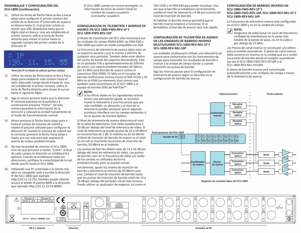
Entradas de RFEthernet-48 V y retorno
Transmisor óp co
Divisor de avance
Nodo
Transmisor óp co Nodo
Transmisor óp co
Receptor óp co
Combinador inverso
SALIDA DE RF
Panel posterior del SCU-1800
Receptor óp co
Planta externaCabecera/centro
Receptor óp co
Nodo
Combinador de avance
TX
El SCU-1800 cuenta con acceso protegido. La información de inicio de sesión inicial es: nombre de usuario scuadmin contraseña: scuadmin
CONFIGURACIÓN DE TELEMETRÍA Y BARRIDO DE AVANCE EN SCU-1800-FWD-REV-1P Y SCU-1800-FWD-REV-16PEl Modo de transmisión del SCU sólo funcionará con las unidades de campo DSAM-6300, las ONX-630 o SDA-5000 que estén en modo compa ble con SDA.La Frecuencia de telemetría de avance debe estar en un espectro vacante y por lo menos a 500 kHz de cualquier otro portador. También debe estar dentro del ancho de banda del espectro descendente. Este es un portador FSK y aproximadamente de 500 kHz de ancho. Los valores predeterminados de fábrica son 51 MHz para Barrido de avance (como el transmisor SDA-5500), 52 MHz en el receptor de barrido mul usuario inverso (como el SDA-5510) y 53 MHz en el HSM (un elemento Viavi común que también suele encontrarse en el SCU-1800 y el equipo de barrido SDA) de PathTrak™.
NOTA: Si los filtros diplex en los ingredientes ac vos
enen una atenuación aguda, se aconseja mover la telemetría a una frecuencia que sea más confiable. La ubicación y el nivel de la telemetría pueden provocar que el segundo armónico interfiera con los canales existentes si no se ajustan de manera óp ma.
El Nivel de telemetría de avance determina el nivel de la señal de telemetría. Este debe establecerse a 10 dB por debajo del nivel de referencia de vídeo. El nivel de telemetría se puede ajustar de 20 a 50 dBmV en incrementos de 1 dB. El máximo es de 50 dBmV; el Nivel de inserción de barrido de avance es el nivel en el cuál se insertarán los puntos de inserción de barrido; 50 dBmV es el máximo. Los puntos de barrido deben estar de 14 a 16 dB por debajo del nivel de referencia de vídeo. Los puntos de barrido caen en la frecuencia de vídeo y/o audio de los canales no u lizados de forma predeterminada, pero se pueden mover.Inicialmente, ajuste los niveles de inserción de barrido y telemetría al mínimo de 20 dBmV cada uno. Cambie el nivel de inserción de barrido hasta que los puntos de inserción de barrido estén de 14 a 16 dB por debajo del portador visual más cercano. Puede u lizar un analizador de espectro, tal como el
VSE-1100 o el ONX-630 para poder visualizar. Una vez que el barrido se establezca correctamente, cambie el nivel de telemetría a 4 dB por encima del nivel de Inserción de barrido.Al habilitar el Barrido inverso permi rá que el barrido inverso empiece a funcionar. Si se deshabilita, el barrido de avance será más rápido.
CONFIGURACIÓN DE TELEMETRÍA DE AVANCE EN LAS UNIDADES DE BARRIDO INVERSO MULTIUSUARIO SCU-1800-REV-MU-1P Y SCU-1800-REV-MU-16PLas unidades mul usuario u lizan una telemetría de avance para comunicarse con los instrumentos de campo para transmi r los resultados de barrido e instruir a la unidad de campo dónde y cuándo transmi r los pulsos de barrido.Siga las mismas pautas para la configuración de telemetría de avance según se describe en la configuración de barrido de avance.
CONFIGURACIÓN DE BARRIDO INVERSO EN SCU-1800-FWD-REV-1P Y SCU-1800-FWD-REV-16P, SCU-1800-REV-MU-1P Y SCU-1800-REV-MU-16P La Frecuencia de telemetría inversa está configurada en el SCU-1800 y no en la unidad de campo.
NOTA: Asegúrese de seleccionar un vacío de frecuencia confiable de interferencia en la parte más estable de la banda de paso, no en la caída o por debajo de 15 MHz.
Los Planos de canal inverso se construyen y/o editan para el sen do ascendente. El plano de canal inverso debe ponerse en marcha en la unidad que va a recibir los puntos de barrido desde el receptor ascendente (ya sea el SCU-1800-FWD-REV-1P/16P o el SCU-1800-REV-MU-1P/16P).El plano de barrido inverso será comunicado automá camente a las unidades de campo a través de la telemetría de avance.
DESEMBALAJE Y CONFIGURACIÓN DEL SCU-1800 (con nuación)
11. U lice las teclas de flecha hacia arriba o hacia abajo para configurar el primer número del octeto de la dirección IP (intervalo de espacio en blanco hasta 2). Si el primer octeto es menor que 100, desplácese hasta que el dígito esté en blanco. Una vez establecido el primer número, u lice la tecla de flecha derecha para mover el cursor hasta el segundo número del primer octeto de la dirección IP.
Dirección IP en Modo de edición (primer octeto)
12. U lice las teclas de flecha hacia arriba o hacia abajo para establecer este número hasta el valor adecuado (rango desde 0 hasta 9). Una vez establecido el primer número, u lice la tecla de flecha derecha para mover el cursor hasta el siguiente dígito.
13. Siga el mismo proceso hasta que la dirección IP correcta aparezca en la pantalla y a con nuación presione "Entrar". De esta manera guardará la información de la dirección y colocará la unidad nuevamente en el modo de funcionamiento normal.
14. Ahora presione la flecha hacia abajo para ir hasta el campo de máscara de subred y repe r el proceso u lizado para configurar la dirección IP. Cuando la máscara de subred sea la correcta, presione la flecha hacia abajo y repita una vez más para que aparezca la puerta de enlace predeterminada.
15. No hay necesidad de reiniciar el SCU-1800. Una vez que presione el botón "Entrar" al final de cada campo, la dirección se establecerá y aplicará. Cuando se establezcan todas las direcciones, verifique la conec vidad de la red desde una PC hasta el SCU-1800.
16. U lizando una PC conectada a la misma red, abra un navegador web y escriba la dirección IP del SCU-1800 (por ejemplo h p://10.11.15.55). También puede obtener acceso al añadir el puerto 8000 a la dirección (por ejemplo h p://10.11.15.55:8000).
SCU-1800 AUSPACKEN UND EINRICHTEN1. SCU-1800 aus dem Karton nehmen und
Verpackungsmaterial vorsich g en ernen.2. SCU-1800 Chassis mithilfe der vier Löcher an
der Vorderseite im Rack mon eren.3. Erdungsriemen der Chassis an die Erdungsan-
schlussschrauben an der Rückseite des SCU-1800 anschließen.
4. Schutzabdeckung über den Gleichstroman-schlussösen an der Rückseite des SCU-1800 en ernen.a. Bei Verwendung einer vorhandenen
-48-V-Gleichstorm-Stromversorgung nochmals prüfen, ob der Strom abgeschaltet ist. -48-V- und RTN-Kabel von der Stromversorgung zu den entsprechen-den Stromanschlussösen an der Rückseite des SCU-1800 anschließen.
b. Bei Verwendung eines von VIAVI geliefer-ten op onalen Wechselstrom-Adapters die Adapteranschlüsse an die entsprechenden Stromanschlussösen am SCU-1800 anschließen. Die schwarze Ader wird mit der -48-V-Gleichstorm-Anschlussöse und die weiße Ader an die RTN-Anschlussöse verbunden.
5. Durchsich ge Kunststoffabdeckung wieder über den Stromanschlussösen anbringen.
6. Jumper von der HF-Quelle an die entsprechen-den Empfangsports an der Rückseite des SCU-1800, wie im Anschlussplan angegeben, anschließen.
Den HF AUS-Port wie dargestellt anschließen. Port 1 am Empfangsport ist der einzige ak ve Rückwärts-Sweep-Empfangsport am SCU-1800-FWD-REV-1P und SCU-1800-MU-REV-1P.
Ports 1 bis 16 sind alle ak ve Rückwärts-Sweep-Ports am SCU-1800-FWD-REV-16 und SCU-1800- MU-REV-16P.
Die Rückwärts-Zuleitungen für das Rückwärts-Sweeping sollten entsprechend an einen der Empfangsports angeschlossen werden.
Empfangsports
Die Rückleitungspegel sollten für op male Leistung idealerweise bei 0 dBmV empfangen werden, funk onieren aber je nach gesamtem kombiniertem Grundrauschen auch über den Bereich von +/- 10 dBmV. Für den ordnungs-gemäßen Empfang muss die Rückwärts-Teleme-trie > 20 dB SNR sein.
HINWEIS: SCU-1800-FWD-REV-1P und SCU-1800- FWD-REV-16P werden nicht genauso angeschlossen wie der SDA- 5500 für Vorwärts-Sweep. Die Vorwärtspegel werden vom SCU-1800 nicht direkt gemessen. Die Stabilität und Genauigkeit des Senders verringern die Notwendigkeit der lokalen Messung.VORSICHT: Vorwärts-Pfadsignale NICHT an einen der 16 Empfangsports anschließen.
7. Ethernet-Zuleitung an die RF45-An-schlussbuchse an der Rückseite des SCU-1800 anschließen.
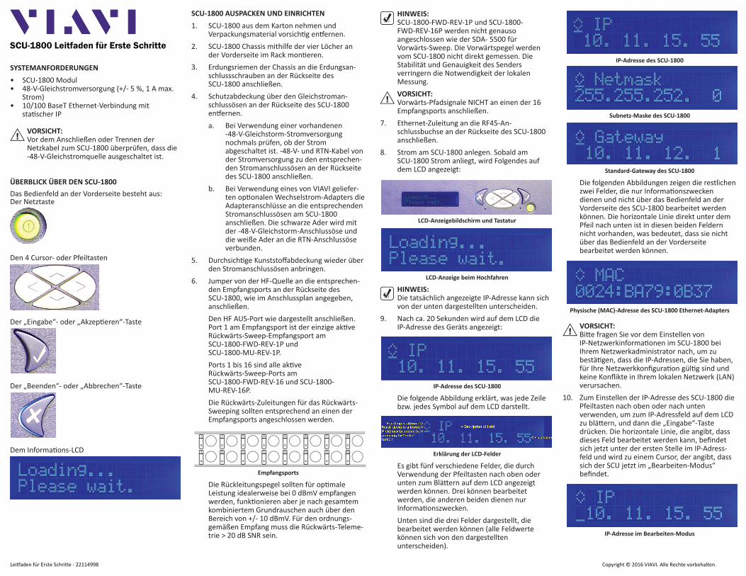
8. Strom am SCU-1800 anlegen. Sobald am SCU-1800 Strom anliegt, wird Folgendes auf dem LCD angezeigt:
LCD-Anzeigebildschirm und Tastatur
LCD-Anzeige beim Hochfahren
HINWEIS: Die tatsächlich angezeigte IP-Adresse kann sich von der unten dargestellten unterscheiden.
9. Nach ca. 20 Sekunden wird auf dem LCD die IP-Adresse des Geräts angezeigt:
IP-Adresse des SCU-1800
Die folgende Abbildung erklärt, was jede Zeile bzw. jedes Symbol auf dem LCD darstellt.
Erklärung der LCD-Felder
Es gibt fünf verschiedene Felder, die durch Verwendung der Pfeiltasten nach oben oder unten zum Blä ern auf dem LCD angezeigt werden können. Drei können bearbeitet werden, die anderen beiden dienen nur Informa onszwecken.
Unten sind die drei Felder dargestellt, die bearbeitet werden können (alle Feldwerte können sich von den dargestellten unterscheiden).
IP-Adresse des SCU-1800
Subnetz-Maske des SCU-1800
Standard-Gateway des SCU-1800
Die folgenden Abbildungen zeigen die restlichen zwei Felder, die nur Informa onszwecken dienen und nicht über das Bedienfeld an der Vorderseite des SCU-1800 bearbeitet werden können. Die horizontale Linie direkt unter dem Pfeil nach unten ist in diesen beiden Feldern nicht vorhanden, was bedeutet, dass sie nicht über das Bedienfeld an der Vorderseite bearbeitet werden können.
Physische (MAC)-Adresse des SCU-1800 Ethernet-Adapters
VORSICHT:Bi e fragen Sie vor dem Einstellen von IP-Netzwerkinforma onen im SCU-1800 bei Ihrem Netzwerkadministrator nach, um zu bestä gen, dass die IP-Adressen, die Sie haben, für Ihre Netzwerkkonfigura on gül g sind und keine Konflikte in Ihrem lokalen Netzwerk (LAN) verursachen.
10. Zum Einstellen der IP-Adresse des SCU-1800 die Pfeiltasten nach oben oder nach unten verwenden, um zum IP-Adressfeld auf dem LCD zu blä ern, und dann die „Eingabe“-Taste drücken. Die horizontale Linie, die angibt, dass dieses Feld bearbeitet werden kann, befindet sich jetzt unter der ersten Stelle im IP-Adress-feld und wird zu einem Cursor, der angibt, dass sich der SCU jetzt im „Bearbeiten-Modus“ befindet.
VORSICHT: Vor dem Anschließen oder Trennen der Netzkabel zum SCU-1800 überprüfen, dass die -48-V-Gleichstromquelle ausgeschaltet ist.
ÜBERBLICK ÜBER DEN SCU-1800Das Bedienfeld an der Vorderseite besteht aus:Der Netztaste
Den 4 Cursor- oder Pfeiltasten
Der „Eingabe“- oder „Akzep eren“-Taste
Der „Beenden“- oder „Abbrechen“-Taste
Dem Informa ons-LCD
Lei aden für Erste Schri e - 22114998
Op scherSender
Vorwärts-Spli er
Knoten
Op scherSender Knoten
Op scherSender
Op scher Empfänger
Rückwärts-Combiner
HF AUS
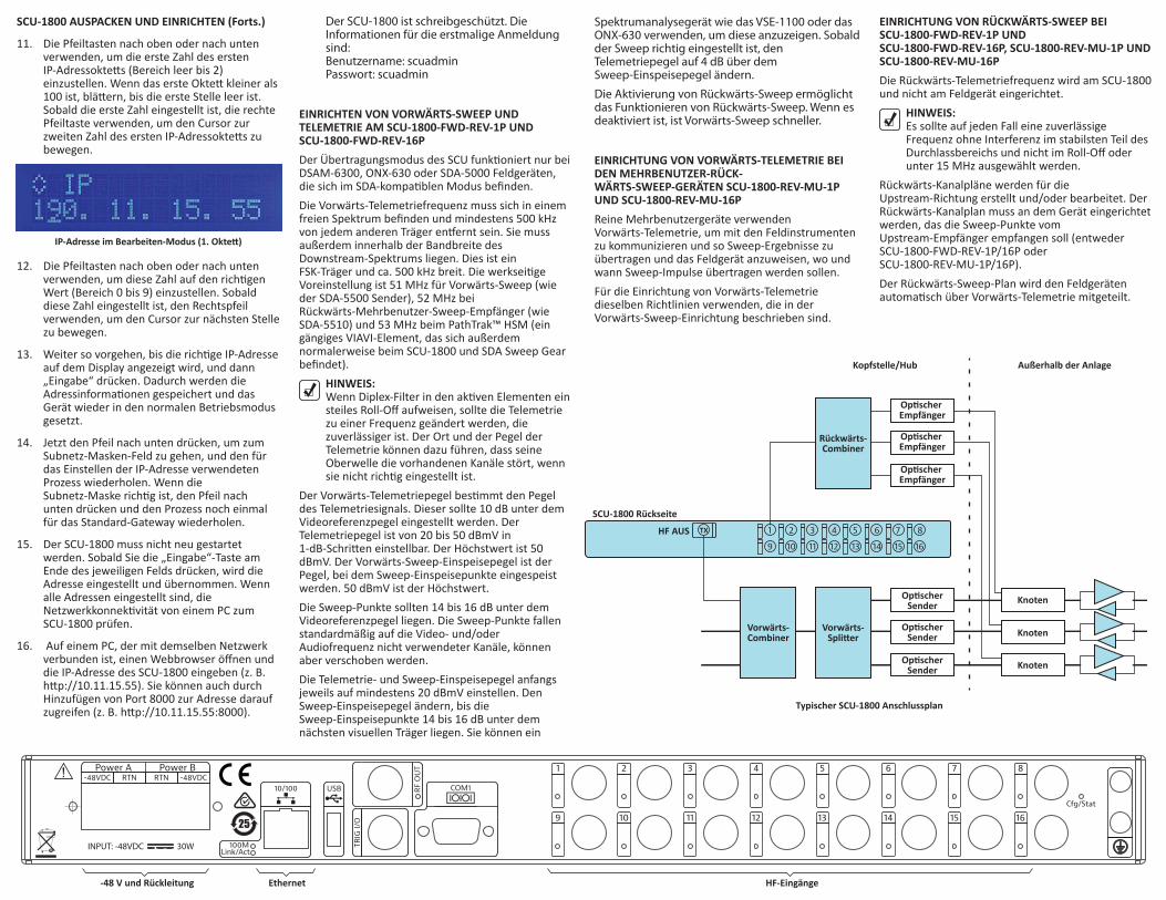
SCU-1800 Rückseite
Op scher Empfänger
Außerhalb der AnlageKopfstelle/Hub
Op scher Empfänger
Knoten
Vorwärts-Combiner
TX
HF-EingängeEthernet-48 V und Rückleitung
Der SCU-1800 ist schreibgeschützt. Die Informationen für die erstmalige Anmeldung sind:Benutzername: scuadminPasswort: scuadmin
EINRICHTEN VON VORWÄRTS-SWEEP UND TELEMETRIE AM SCU-1800-FWD-REV-1P UND SCU-1800-FWD-REV-16P Der Übertragungsmodus des SCU funk oniert nur bei DSAM-6300, ONX-630 oder SDA-5000 Feldgeräten, die sich im SDA-kompa blen Modus befinden.Die Vorwärts-Telemetriefrequenz muss sich in einem freien Spektrum befinden und mindestens 500 kHz von jedem anderen Träger en ernt sein. Sie muss außerdem innerhalb der Bandbreite des Downstream-Spektrums liegen. Dies ist ein FSK-Träger und ca. 500 kHz breit. Die werksei ge Voreinstellung ist 51 MHz für Vorwärts-Sweep (wie der SDA-5500 Sender), 52 MHz bei Rückwärts-Mehrbenutzer-Sweep-Empfänger (wie SDA-5510) und 53 MHz beim PathTrak™ HSM (ein gängiges VIAVI-Element, das sich außerdem normalerweise beim SCU-1800 und SDA Sweep Gear befindet).
HINWEIS: Wenn Diplex-Filter in den ak ven Elementen ein steiles Roll-Off aufweisen, sollte die Telemetrie zu einer Frequenz geändert werden, die zuverlässiger ist. Der Ort und der Pegel der Telemetrie können dazu führen, dass seine Oberwelle die vorhandenen Kanäle stört, wenn sie nicht rich g eingestellt ist.
Der Vorwärts-Telemetriepegel bes mmt den Pegel des Telemetriesignals. Dieser sollte 10 dB unter dem Videoreferenzpegel eingestellt werden. Der Telemetriepegel ist von 20 bis 50 dBmV in 1-dB-Schri en einstellbar. Der Höchstwert ist 50 dBmV. Der Vorwärts-Sweep-Einspeisepegel ist der Pegel, bei dem Sweep-Einspeisepunkte eingespeist werden. 50 dBmV ist der Höchstwert. Die Sweep-Punkte sollten 14 bis 16 dB unter dem Videoreferenzpegel liegen. Die Sweep-Punkte fallen standardmäßig auf die Video- und/oder Audiofrequenz nicht verwendeter Kanäle, können aber verschoben werden.Die Telemetrie- und Sweep-Einspeisepegel anfangs jeweils auf mindestens 20 dBmV einstellen. Den Sweep-Einspeisepegel ändern, bis die Sweep-Einspeisepunkte 14 bis 16 dB unter dem nächsten visuellen Träger liegen. Sie können ein
Spektrumanalysegerät wie das VSE-1100 oder das ONX-630 verwenden, um diese anzuzeigen. Sobald der Sweep richtig eingestellt ist, den Telemetriepegel auf 4 dB über dem Sweep-Einspeisepegel ändern.
Die Aktivierung von Rückwärts-Sweep ermöglicht das Funktionieren von Rückwärts-Sweep. Wenn es deaktiviert ist, ist Vorwärts-Sweep schneller.
EINRICHTUNG VON VORWÄRTS-TELEMETRIE BEI DEN MEHRBENUTZER-RÜCK-WÄRTS-SWEEP-GERÄTEN SCU-1800-REV-MU-1P UND SCU-1800-REV-MU-16PReine Mehrbenutzergeräte verwenden Vorwärts-Telemetrie, um mit den Feldinstrumenten zu kommunizieren und so Sweep-Ergebnisse zu übertragen und das Feldgerät anzuweisen, wo und wann Sweep-Impulse übertragen werden sollen.Für die Einrichtung von Vorwärts-Telemetrie dieselben Richtlinien verwenden, die in der Vorwärts-Sweep-Einrichtung beschrieben sind.
EINRICHTUNG VON RÜCKWÄRTS-SWEEP BEI SCU-1800-FWD-REV-1P UND SCU-1800-FWD-REV-16P, SCU-1800-REV-MU-1P UND SCU-1800-REV-MU-16PDie Rückwärts-Telemetriefrequenz wird am SCU-1800 und nicht am Feldgerät eingerichtet.
HINWEIS: Es sollte auf jeden Fall eine zuverlässige Frequenz ohne Interferenz im stabilsten Teil des Durchlassbereichs und nicht im Roll-Off oder unter 15 MHz ausgewählt werden.
Rückwärts-Kanalpläne werden für die Upstream-Richtung erstellt und/oder bearbeitet. Der Rückwärts-Kanalplan muss an dem Gerät eingerichtet werden, das die Sweep-Punkte vom Upstream-Empfänger empfangen soll (entweder SCU-1800-FWD-REV-1P/16P oder SCU-1800-REV-MU-1P/16P).Der Rückwärts-Sweep-Plan wird den Feldgeräten automa sch über Vorwärts-Telemetrie mitgeteilt.
SCU-1800 AUSPACKEN UND EINRICHTEN (Forts.)
11. Die Pfeiltasten nach oben oder nach unten verwenden, um die erste Zahl des ersten IP-Adressokte s (Bereich leer bis 2) einzustellen. Wenn das erste Okte kleiner als 100 ist, blä ern, bis die erste Stelle leer ist. Sobald die erste Zahl eingestellt ist, die rechte Pfeiltaste verwenden, um den Cursor zur zweiten Zahl des ersten IP-Adressokte s zu bewegen.
IP-Adresse im Bearbeiten-Modus (1. Okte )
12. Die Pfeiltasten nach oben oder nach unten verwenden, um diese Zahl auf den rich gen Wert (Bereich 0 bis 9) einzustellen. Sobald diese Zahl eingestellt ist, den Rechtspfeil verwenden, um den Cursor zur nächsten Stelle zu bewegen.
13. Weiter so vorgehen, bis die rich ge IP-Adresse auf dem Display angezeigt wird, und dann „Eingabe“ drücken. Dadurch werden die Adressinforma onen gespeichert und das Gerät wieder in den normalen Betriebsmodus gesetzt.
14. Jetzt den Pfeil nach unten drücken, um zum Subnetz-Masken-Feld zu gehen, und den für das Einstellen der IP-Adresse verwendeten Prozess wiederholen. Wenn die Subnetz-Maske rich g ist, den Pfeil nach unten drücken und den Prozess noch einmal für das Standard-Gateway wiederholen.
15. Der SCU-1800 muss nicht neu gestartet werden. Sobald Sie die „Eingabe“-Taste am Ende des jeweiligen Felds drücken, wird die Adresse eingestellt und übernommen. Wenn alle Adressen eingestellt sind, die Netzwerkkonnek vität von einem PC zum SCU-1800 prüfen.
16. Auf einem PC, der mit demselben Netzwerk verbunden ist, einen Webbrowser öffnen und die IP-Adresse des SCU-1800 eingeben (z. B. h p://10.11.15.55). Sie können auch durch Hinzufügen von Port 8000 zur Adresse darauf zugreifen (z. B. h p://10.11.15.55:8000). Typischer SCU-1800 Anschlussplan