Jun 30/01 28-00-00 Page 1 EFFECTIVITY: All z SD3-60 AIRCRAFT MAINTENANCE MANUAL AMM 28-00-00 FUEL SYSTEM - GENERAL Fuel is stored in two box-shaped containers mounted fore and aft within a faired compartment on top of the fuselage centre-section. The forward container is laterally sub-divided by two bulkheads to form three separate cells, which from the forward end are known as Cell 1,2 and 3 respectively (the aft container being Cell 4). The cells are operationally coupied, Cell 1 and 2 being collectively regarded as the forward tank and Cell 3 and 4 as the aft tank. Each tank gravity feeds a small collector tank mounted within the fuselage right -hand sidewall. The collector tanks provide sufficient fuel for not less than ten seconds operation of the engines under negative gravity conditions. A booster pump is incorporated in each collector tank. The pumps in the forward and aft collector tanks normally supply fuel, via two L.P. fuel control valves to the left and right engines respectively. Warning of pump failure is afforded by the illumination of the appropriate of two low fuel pressure warning lights on flight compartment panel 1P. Refer to 28-22-00, pb1. A normally closed crossfeed valve which segregates the two engine supply lines is operationally opened only in those circumstances detailed. Tank replenishment is accomplished by: - use of the low level refuel/defuel system. Refer to 28-21-00, pb1. - by gravity feed through tank roof mounted filler caps. Both main tanks share a common vent system which:- (1) Allows free venting of the tank air spaces without loss of fuel in any likely aircraft attitude. (2) Protects the tanks in the event of mal-functioning of the pressure refuel/defuel system. Refer to 28-42-00, pb1. An Intertechnique capacitance type contents gauging system is installed to provide continuous indication of the contents in the tanks. Contents gauges for each tank are mounted on the flight deck roof panel 4P and on the ground refuel/defuel panel 8P.
Transcript
Jun 30/0128-00-00 Page 1EFFECTIVITY: All
zSD3-60 AIRCRAFT MAINTENANCE MANUAL
AMM28-00-00 2.0.0.0FUEL SYSTEM - GENERAL
Fuel is stored in two box-shaped containers mounted fore and aft within a faired compartment on top of the fuselage centre-section. The forward container is laterally sub-divided by two bulkheads to form three separate cells, which from the forward end are known as Cell 1,2 and 3 respectively (the aft container being Cell 4).
The cells are operationally coupied, Cell 1 and 2 being collectively regarded as the forward tank and Cell 3 and 4 as the aft tank.
Each tank gravity feeds a small collector tank mounted within the fuselage right -hand sidewall. The collector tanks provide sufficient fuel for not less than ten seconds operation of the engines under negative gravity conditions.
A booster pump is incorporated in each collector tank. The pumps in the forward and aft collector tanks normally supply fuel, via two L.P. fuel control valves to the left and right engines respectively. Warning of pump failure is afforded by the illumination of the appropriate of two low fuel pressure warning lights on flight compartment panel 1P. Refer to 28-22-00, pb1. A normally closed crossfeed valve which segregates the two engine supply lines is operationally opened only in those circumstances detailed.
Tank replenishment is accomplished by:
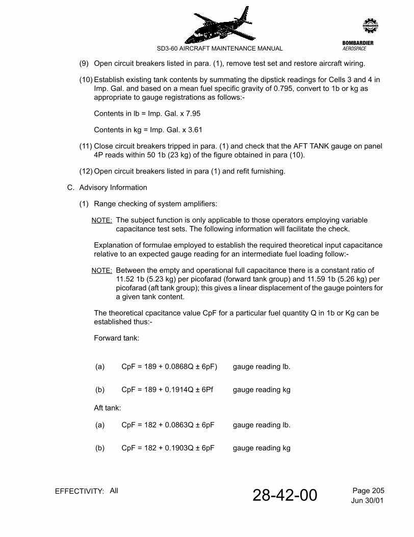
- use of the low level refuel/defuel system. Refer to 28-21-00, pb1. - by gravity feed through tank roof mounted filler caps.
Both main tanks share a common vent system which:-
(1) Allows free venting of the tank air spaces without loss of fuel in any likely aircraft attitude.
(2) Protects the tanks in the event of mal-functioning of the pressure refuel/defuel system.
Refer to 28-42-00, pb1. An Intertechnique capacitance type contents gauging system is installed to provide continuous indication of the contents in the tanks. Contents gauges for each tank are mounted on the flight deck roof panel 4P and on the ground refuel/defuel panel 8P.
Jun 30/0128-00-00 Page 2EFFECTIVITY: All
zSD3-60 AIRCRAFT MAINTENANCE MANUAL
Fuel SystemFigure 1
Dec 18/0728-00-00 Page 201EFFECTIVITY: All
zSD3-60 AIRCRAFT MAINTENANCE MANUAL
AMM28-00-00 1.0.0.0FUEL SYSTEM - MAINTENANCE PRACTICES
1. Fuel Safety Precautions
A. General
The maintenance procedure that follows is for fuel safety precautions. You must use these safety precautions when you do work on a fuel system component or in a fuel tank.
B. Procedure
(1) Obey all fuel-system safety precautions that follow:-
(a) Before you do maintenance on the fuel system, make sure that all persons fully know the maintenance practices that follow. To keep the system serviceable, carefully and accurately obey these practices.
(b) Obey all local safety regulations during fuel system maintenance.
(c) Do fuel system maintenance only in areas where free movement of fire fighting equipment and other emergency equipment is possible. Sufficient fire fighting equipment and persons who know how to use it must be immediately available at all times.
(d) Make sure that the wind does not move fuel fumes to a building in which fuel fumes can collect.
(e) Make sure that the wind does not move fuel fumes to a flame or equipment that causes sparks.
(f) Remove from the aircraft maintenance area all equipment that can cause sparks such as:-
1 Electrically-powered tools
2 Vacuum cleaners
3 Electronic test equipment.
(g) Connect the grounding cable to an approved ground and to an aircraft ground point.
(h) Ground the maintenance stands to the same ground as the aircraft.
(i) Bond the air mover to the aircraft.
(j) Do not smoke or use a flame near the aircraft.
(k) If you discard fuel, obey all of the applicable regulations.
(l) Prevent fuel leakage because of the risk of a fire.
Dec 18/0728-00-00 Page 202EFFECTIVITY: All
zSD3-60 AIRCRAFT MAINTENANCE MANUAL
(m) If there is fuel leakage, do the steps that follow:-
1 Stop all work in the area until the fuel is removed
2 Clean the area
3 Make sure that the area is safe.
(2) Obey all the health safety precautions that follow:-
(a) Do not get fuel in your eyes or on your skin. If you get fuel in your eyes or on your skin, do the steps that follow:-
1 Flush your eyes with water
2 Flush your skin with water
3 If irritation occurs, get medical aid.
(b) Do not get fuel in your mouth or in your nose. If you get fuel in your mouth or in your nose, get medical aid immediately.
(c) Do not breathe fuel fumes. If a person breathes a high concentration of fuel fumes, a person can get headaches, become drowsy, or faint. If a person’s breathing becomes slow or stops, use continuous artificial respiration and get medical aid.
(d) Supply clean air if the person has headaches or eye irritations.
(3) Obey all the electrical safety precautions that follow:-
(a) When you disconnect electrical connectors, put protective covers on them. Do not let fuel, moisture, or other unwanted material go in the electrical connectors.
(b) Do not use electrical test equipment that can cause sparks in a fuel tank.
(c) Do not connect or disconnect electrical equipment to or from energized outlets that are less than 100 feet from an open fuel tank or a fuel leakage.
(d) Use lamps that are resistant to explosion, have good electrical connections, and have serviceable extension cords.
(e) Use explosion resistant floodlights and extension cords for external lighting.
(4) Obey the electrostatic discharge precautions that follow:-
(a) Use cotton coveralls with buttons or zippers that do not cause sparks in the fuel tanks.
(b) Do not put on wool, silk, nylon, or other synthetic clothing.
Dec 18/0728-00-00 Page 203EFFECTIVITY: All
zSD3-60 AIRCRAFT MAINTENANCE MANUAL
(c) Use only sponges and cotton rags to absorb fuel. If you use other materials, you can cause a static discharge.
(d) Do not safety units or fittings in the fuel tanks with lockwire. The end of the wire could be the point of electrostatic discharge.
WARNING: WARNING: DO NOT USE STEEL WOOL OF ANY TYPE IN THE FUEL TANKS. PIECES OF STEEL WOOL CAN BREAK OFF AND CAUSE DAMAGE OR AN EXPLOSION IF THEY TOUCH ELECTRICAL COMPONENTS.
(5) Obey the safety precautions about the tools and equipment that follow:-
(a) Keep a list of all the tools, equipment and materials when they go in and out of the fuel tank. Before you close the tank, make sure you remove all of the items on the list from the fuel tank.
(b) Persons who do work near open fuel tanks must not have the items that follow:-
1 Metal objects
2 Matches
3 Pocket warmers
4 Shoes with metal clips or nails
5 Jewellery
6 Hearing-aid devices or other battery-operated equipment.
7 Steel wool of any type.
(c) Use only air-driven power tools in the fuel tank.
(d) Do not use metal boxes or other types of containers with sharp or rough edges in the fuel tank. This can cause damage to the fuel tank.
(e) When you have tools in the fuel tank, use containers that do not make static electricity and have rounded corners. If you use a sharp-edged tool in the fuel tank, put it in an applicable container when the work is completed.
(6) Obey the safety precautions about contamination in the fuel tank that follow:-
(a) When you go in the fuel tanks, use hair covers, shoe covers, and clean, cotton coveralls that have no lint. Clean the cuffs of the pants to remove all the dirt or lint.
(b) Make sure that all equipment that you put in the fuel tanks has no dirt and dust.
(c) Make sure that the air ducts that supply air in the fuel tanks are internally and externally clean.
Dec 18/0728-00-00 Page 204EFFECTIVITY: All
zSD3-60 AIRCRAFT MAINTENANCE MANUAL
(d) Make sure that all the equipment used to supply air has sufficient filters.
(e) Do not let dirt, dust, or other unwanted materials get in the fuel tank.
(f) Remove all the unwanted material from the open fuel tanks with a vacuum hose.
(g) Close all of the tanks when maintenance stops.
(h) Put a cap or plug on all lines and components that are disconnected or removed. Do not let unwanted material go in the lines or components.
(i) Use a air vacuum hose in the fuel tank after you do a large quantity of work in the fuel tank.
Jun 30/0128-00-01 Page 201EFFECTIVITY: All
zSD3-60 AIRCRAFT MAINTENANCE MANUAL
AMM28-00-01 3.0.0.0TEMPORARY REPLACEMENT OF DAMAGED RIGID PIPES BY FLEXIBLE PIPES - MAINTENANCE PRACTICES
1. Servicing
Refer to 20-09-08, pb201.
Jun 30/0128-11-00 Page 1EFFECTIVITY: All
zSD3-60 AIRCRAFT MAINTENANCE MANUAL
AMM28-11-00 4.0.0.0STORAGE - DESCRIPTION
1. Description
A. General
The fuel storage tanks, forward and aft, are respectively located between Stns.175 to 261 and 320 to 375 within a faired compartment on the fuselage roof. The cellular arrangement of the tanks is such that Cells 1 and 2 are operationally regarded as the forward tank and Cells 3 and 4 the aft tank. Both tanks share a vent system, Refer to 28-12-00, pb1.
The construction of the fuel storage tanks is described in paras. B and C.
B. Forward container
The forward container is designed such that:-
(a) its upper skin panelling matches the profiling of the fuselage roof fairing and
(b) its rear flooring area is raised to clear a projected 'rotor burst area' (to preclude simultaneously penetration of the container and the passenger compartment by a rotor segment in the event of a major engine catastrophe).
Structurally the container consists of a light alloy box, comprised of side, forward and aft walls covered with roof and floor panels. Sealant compounds PR1221 and PR1221BT are employed to seal all joints, rivets and doublers on the structure.
The unit is internally segregated into three separate cells by two lateral bulkheads. These are jointed assemblies on each side of an anti-surge baffle rib fixed at the longitudinal centre-line of the container. The forward and centre cells (No.1 and 2) are each additionally provided with a baffle frame which laterally crosses the container. The walls, bulkheads and baffles are strengthened in the main by vertical stiffeners.
The roof panel is of sheeted stringer construction and incorporates two filler caps, one each to Cell 1 and 2; these provide for gravity refuelling of the forward tank as an alternative to the low level refuel/defuel system. Refer to 28-21-00, pb1. Six access panels, two to each cell, provide access to the following internal equipment:-
- Fuel contents probes- Main vent system components and piping. Refer to 28-12-00, pb1.- Float switches and check piping low level refuel/defuel system- Piping - collector tank vents and engine-mounted fuel control unit air purge- Gravity feed outlet adapters.
The gravity feed outlet adapters are screened assemblies fitted to the container floor, these connect with the gravity feed piping which deliver fuel to the collector tanks in the fuselage right sidewall. The six forward adapters (four in Cell 1 and two in Cell 2) serve the forward collector tank - the remaining adapter (Cell 3), together with four in the aft container (para C) serve the aft collector tank.
Jun 30/0128-11-00 Page 2EFFECTIVITY: All
zSD3-60 AIRCRAFT MAINTENANCE MANUAL
Container attachment to the fuselage roof is afforded by:-
- Two brackets fixed to the bottom outboard ends of the rear bulkhead of Cell 1.- Two support feet fixed to the elevated bottom outboard ends of the containers rear wall.
An attachment bolt and washer fitted at each of the four positions are secured to a trapnut below the fuselage roof skin.
NOTE: (a) The forward, left attachment positively locates the unit, the remaining three attachments permit unit installed flexing as detailed below.
(b) All four bolt heads are secured by steel locking plates which attach to the fuselage skin.
C. Aft container
The aft container (Cell 4) is, like the forward container (para B.) designed such that its upper panelling matches the profile of the fuselage roof fairing.
Structurally the container consists of a light alloy box, comprised of side, forward and aft walls covered with roof and floor panels. Sealant compounds PR 1221 and PR 1221 BT are employed to seal all joints, rivets and doublers on the structure.
The unit incorporates two anti-surge baffle frames; these are jointed assemblies on each side of a baffle rib fixed at the longitudinal centre-line of the container.
The roof panel, which is of sheeted stringer construction, incorporates a filler cap to provide for gravity refuelling as an alternative to use of the low level refuel/defuel system. Refer to 28-21-00, pb1.). Four access panels provide access to:-
(1) Fuel contents probes
(2) Main vent system components and piping
(3) Float switch and check piping - low level refuel/defuel system
(4) Gravity feed outlet connectors
The screened gravity-feed outlet adapters are identical to those employed in the forward container. Four are fitted, one in each corner of the container floor; these in conjunction with the single adapter in Cell 3 of the forward container (para B) are connected by feed piping to the aft collector tank.
(i) forward, right - lateral flexing of ± 0.10 in.(ii) aft, left - longitudinal flexing of ± 0.10 in.(iii) aft, right - 0.10 in. flexing in any direction
Jun 30/0128-11-00 Page 3EFFECTIVITY: All
zSD3-60 AIRCRAFT MAINTENANCE MANUAL
Container attachment to the fuselage roof is afforded by four brackets fixed to the bottom corners of the unit; these are each secured by a bolt and washer to a trapnut below the fuselage roof skin.
NOTE: The notes given with respect to attachment of the forward container (para B) again apply.
WARNING: THIS MAINTENANCE PROCEDURE IS RELATED TO THE FUEL TANK SAFETY PROGRAMME AND INCORRECT MAINTENANCE COULD ADVERSELY AFFECT THE DESIGN STANDARDS OF THE FUEL TANK SYSTEM. STRICT ADHERENCE TO THE PROCEDURES IN THIS SECTION IS THEREFORE RECOMMENDED.
1. General
WARNING: ENSURE THAT THE FOLLOWING FIRE PRECAUTIONS ARE OBSERVED WHEN WORKING ON THE FUEL TANKS:-
CHECK THAT ALL ELECTRICAL SUPPLIES IN THE AIRCRAFT ARE OFF. REMOVE THE BATTERIES AND ENSURE THAT GROUND SUPPLY IS NOT CONNECTED TO THE AIRCRAFT.
ENSURE THAT ALL HANDLAMPS OR TORCHES USED TO ILLUMINATE THE INTERIOR OF THE TANKS ARE OF AN APPROVED ‘EXPLOSION PROOF’ DESIGN SUITABLE FOR USE IN ENVIRONMENTS CLASSIFIED BY THE US NATIONAL ELECTRICAL CODE AS DIVISION 1, CLASS 1, GROUPS A, B, C, & D, AND ARE IN GOOD CONDITION.
CONNECT AN EARTH (GROUND) WIRE TO THE AIRCRAFT STRUCTURE, ANY PLATFORMS, AND CASINGS OF ELECTRICALLY POWERED EQUIPMENT USED DURING THIS TASK.
ENSURE THAT SUITABLE FIRE FIGHTING EQUIPMENT IS AVAILABLE AND IS CAPABLE OF REACHING ANY PART OF THE AIRFRAME.
A. Isolate power supplies
(1) Remove the main batteries (refer to 24-33-01, pb201).
(2) Remove the tail emergency battery (refer to 24-33-06, pb201).
(3) Ensure external ground supply is disconnected:-
(a) Close the ground supply connector flap door and secure in closed position with masking tape.
(4) Prominently tag the battery and ground supply locations with a CAUTION, as detailed in chapter 12-09-03, pb1.
2. Remove Forward Tank
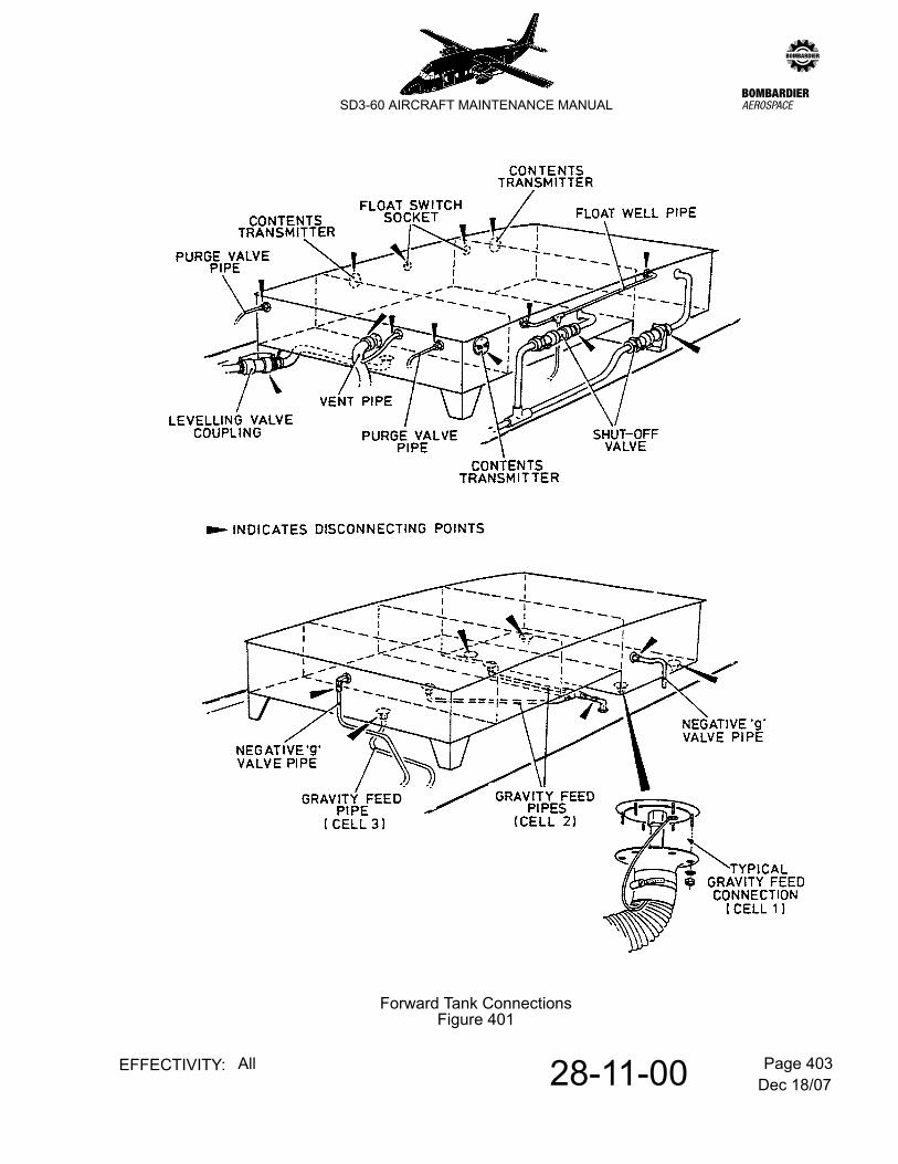
A. Remove the forward tank (cells No.1, 2 & 3)
Refer to Figure 401.
Dec 18/0728-11-00 Page 402EFFECTIVITY: All
zSD3-60 AIRCRAFT MAINTENANCE MANUAL
(1) Drain all fuel from the forward tank
(2) Refer to 6-30-00, pb1. Remove the following forward roof fairing access panels:-
NOTE: Pipework unions and couplings should be disconnected where most convenient. Refer to Figure 401.
(3) Refuel/Defuel connections
(a) Remove locking wire and bonding lead and disconnect both solenoid shut-off valves.
(b) Disconnect both float switch well pipes.
(4) Vent system connections
(a) Remove the locking wire and bonding lead, and disconnect the vent pipe at the rear of the tank cell No.3.
(b) Disconnect the rubber vent connection to cell No.3.
(5) Purge valve connections
(a) Disconnect both purge valve connections at rear of tank (cell No.3).
(6) Levelling valve connection.
(a) Remove locking wire and disconnect levelling valve pipework at tank cell No.3 coupling.
(7) Negative 'G' connections.
(a) Disconnect both negative 'G' connections at tank cells No.1 and 3.
(8) Gravity feed connections
(a) Refer to Figure 401. Disconnect gravity feed pipes from cell No.2 (2 off) at the points indicated. Disconnect gravity feed pipe from cell No.3 where indicated.
(b) Remove appropriate furnishing panels from the passenger compartment fuselage roof between stations 176 and 204 to gain access to the gravity feed connections (4 off) of cell No.1.
Dec 18/0728-11-00 Page 403EFFECTIVITY: All
zSD3-60 AIRCRAFT MAINTENANCE MANUAL
Forward Tank ConnectionsFigure 401
Dec 18/0728-11-00 Page 404EFFECTIVITY: All
zSD3-60 AIRCRAFT MAINTENANCE MANUAL
(c) Refer to Figure 401. Remove six nuts and washers securing each fume-proof ducting flange and disconnect the bonding leads to gain access to the pipe connections. Disconnect the pipes.
(9) Fuel contents transmitters
(a) Disconnect wiring from fuel contents transmitters; two on the left side (cells No.1 and 2) and one on the right side (cell No.3).
(10) Float well switches
(a) Disconnect wiring from float well switches (2 off) on left side of tank cells No.1 & 2.
(11) Tank securing bolts
NOTE: 1: The forward fuel tank is secured by four bolts; two at the rear edge of cell No.1 and two at the rear of cell No.3.
2: Each bolt, complete with sleeve distance piece (if applicable) should be noted to assist with re-assembly.
(a) Remove bolt locking devices and retain for re-assembly.
(b) Release the tank securing bolts and remove the tank (weight approx. 200 lb.) from the aircraft.
3. Install Forward Tank
A. Install the forward tank (cells No.1, 2 & 3)
(1) Place the tank in position on top of the fuselage roof; install securing bolts and sleeve distance pieces as noted during removal.
Torque tighten all securing bolts to 15 lb.ft. with the exception of bolt situated rear left, which is 10 lb.ft. Fit bolt locking devices.
NOTE: Bonding leads freed during removal operations are to be re-attached and tested at a convenient stage during installation in accordance with standard practice. Refer to 20-09-05, pb1 and Refer to 20-09-05, pb201.
(2) Remake all pipework connections previously disconnected in para. 2.A.(3) to (8) and test the refitted bonding leads. Refer to 20-09-05, pb1, para. 6. & 7.
NOTE: 1: Wig-o-Flex couplings i.e. Levelling Valves and Solenoid Shut-off Valves should be hand tightened and AN type couplings should be torque tightened. Refer to 20-09-04, pb1. Wire lock Wig-o-Flex couplings and apply witness marks to all AN couplings.
2: Fume-proof ducting should not be replaced until joints are inspected for leaks.
Dec 18/0728-11-00 Page 405EFFECTIVITY: All
zSD3-60 AIRCRAFT MAINTENANCE MANUAL
(3) Identify and reconnect electrical cables to float well switches.
(4) Taking account of the following note, identify and reconnect electrical cables to the fuel contents transmitters.
IMPORTANT: The fuel contents co-axial connectors must be inspected pre-connecting and externally weather-proofed after connecting. Refer to 28-42-01, pb201.
(5) Refer to 20-09-12, pb201. If tank access was required during tank installation, do an internal visual inspection of the fuel tank before it is refuelled.
(6) Refer to 12-10-28, pb301. Fill the forward tank with fuel and check that the pipe couplings do not leak.
NOTE: Pipework unions and couplings should be disconnected where most convenient. Refer to Figure 402.
(3) Refuel/Defuel connections
(a) Remove locking wire and bonding lead and disconnect the solenoid shut-off valve.
(b) Disconnect the float switch well pipe.
(4) Vent system connections
(a) Remove the locking wire and bonding lead, and disconnect the vent pipe at the forward end of the rear tank.
Dec 18/0728-11-00 Page 406EFFECTIVITY: All
zSD3-60 AIRCRAFT MAINTENANCE MANUAL
(5) Levelling valve connection
(a) Remove locking wire and disconnect levelling valve situated at the forward end of the rear tank.
(6) Gravity feed connections
(a) Remove appropriate furnishing panels from the passenger compartment fuselage roof between stations 320.0 and 374.5 to gain access to the gravity feed connections (4 off) of the rear tank.
(b) Refer to Figure 402. Remove six nuts and washers securing each fume-proof ducting flange and disconnect the bonding leads to gain access to the pipe connections. Disconnect the pipes.
(7) Fuel contents transmitter
(a) Disconnect wiring from fuel contents transmitter situated on right side of tank.
(8) Float well switch
(a) Disconnect wiring from float well switch at plug adjacent to vent connection.
(9) Tank securing bolts
NOTE: 1: The rear fuel tank is secured by four bolts; two at the forward edge and two at the aft edge.
2: Each bolt, complete with sleeve distance piece (if applicable) should be noted to assist with re-assembly.
(a) Remove bolt locking devices and retain for re-assembly.
(b) Release the tank securing bolts and remove the tank (weight approx. 115 lb.) from the aircraft.
5. Install Rear Tank
A. Install the rear tank (cell No.4)
(1) Place the tank in position on top of the fuselage roof; install securing bolts and sleeve distance pieces as noted during removal.
Torque tighten forward and rear securing bolts to 20 lb.ft. and 10 lb.ft. respectively. Fit bolt locking devices.
NOTE: Bonding leads freed during removal operations are to be re-attached and tested at a convenient stage during installation in accordance with standard practice. Refer to 20-09-05, pb1 and Refer to 20-09-05, pb201.
Dec 18/0728-11-00 Page 407EFFECTIVITY: All
zSD3-60 AIRCRAFT MAINTENANCE MANUAL
Aft Tank ConnectionsFigure 402
Dec 18/0728-11-00 Page 408EFFECTIVITY: All
zSD3-60 AIRCRAFT MAINTENANCE MANUAL
(2) Remake all pipework connections previously disconnected in para. 4.A.(3) to (6), and test the refitted bonding leads. Refer to 20-09-05, pb1, para. 6. & 7.
NOTE: 1: Wig-o-Flex couplings i.e. Levelling Valve and Solenoid Shut-Off Valves should be hand tightened and AN type couplings should be torque tightened. Refer to 20-09-04, pb1. Wire lock Wig-o-Flex couplings and apply witness marks to all AN couplings.
2: Fume-proof ducting should not be replaced until joints are inspected for leaks.
(3) Identify and reconnect electrical cable to float well switch.
(4) Taking account of the following note, identify and reconnect electrical cables to the fuel contents transmitters.
IMPORTANT: The fuel contents co-axial connectors must be inspected pre-connecting and externally weather-proofed after connecting. Refer to 28-42-01, pb201.
(5) Refer to 20-09-12, pb201. If tank access was required during tank installation, do an internal visual inspection of the fuel tank before it is refuelled.
(6) Refer to 12-10-28, pb301. Fill the rear tank with fuel and check that the pipe couplings do not leak.
(9) Replace all access panels previously removed in para. 4.A.(2).
(10) Perform fuel contents gauging check. Refer to 28-42-00, pb201.
(11) Perform an engine run.
Jun 30/0128-11-00 Page 501EFFECTIVITY: All
zSD3-60 AIRCRAFT MAINTENANCE MANUAL
AMM28-11-00 6.0.0.0STORAGE - ADJUSTMENT/TEST
1. Pressure testing of tanks
A. General
Following in situ or isolated fuel tank repairs, the unit should be subjected to the tests detailed in para. B or C as appropriate.
WARNING: 1. ADEQUATE SAFETY PRECAUTIONS FOR ALL PERSONNEL ENGAGED ON THE TEST ARE ESSENTIAL AND STRICT FIRE PRECAUTIONS MUST BE MAINTAINED THROUGH-OUT THE TEST PERIOD.
2. FOR PARA. B TESTS, THE SUITABILITY OF THE FIRE FIGHTING EQUIPMENT AND ITS CAPABILITY TO REACH ANY PART OF THE AIRFRAME IS ESSENTIAL AND MUST BE GIVEN DUE CONSIDERATION.
UNAUTHORISED PERSONNEL SHALL BE PREVENTED FROM APPROACHING THE TEST AREA WHEN TESTING IS IN PROGRESS.
B. Test repaired tank/s in situ
Special Tools and Equipment:-
Refuel/defuel truck or hydrant system. (Fuel specifications - Refer to 12-10-28, pb301.)
A separate supply of unweathered fuel suitably stored in drum containers (approx. 60 UK gall. 72 US gall) identical to specification in pressure refuel/defuel facility.
Flexible elbow connections (2) with kerosene resistant inner lining.
(1) Ensure the following:-
(a) that suitable staging has been positioned to give easy and safe access as required.
(b) that all components in the system, the installed system and its associated electrical equipment are scrupulously clean and are operating correctly.
(c) that where necessary, fuel and test equipment is calibrated and in a clean condition.
(d) that the tanks are clean and free from foreign matter which may block tank outlets etc.
(e) that filler caps and dipsticks are securely fastened.
Stack pipe (OD 1.5 in) - as required.Test fill pipe (OD 1.0 in) - as required.
Jun 30/0128-11-00 Page 502EFFECTIVITY: All
zSD3-60 AIRCRAFT MAINTENANCE MANUAL
(2) Test preparation
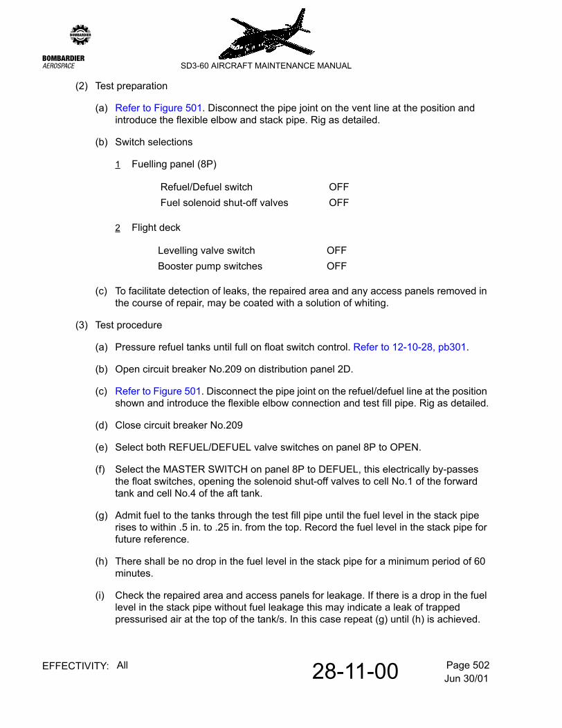
(a) Refer to Figure 501. Disconnect the pipe joint on the vent line at the position and introduce the flexible elbow and stack pipe. Rig as detailed.
(b) Switch selections
1 Fuelling panel (8P)
2 Flight deck
(c) To facilitate detection of leaks, the repaired area and any access panels removed in the course of repair, may be coated with a solution of whiting.
(3) Test procedure
(a) Pressure refuel tanks until full on float switch control. Refer to 12-10-28, pb301.
(b) Open circuit breaker No.209 on distribution panel 2D.
(c) Refer to Figure 501. Disconnect the pipe joint on the refuel/defuel line at the position shown and introduce the flexible elbow connection and test fill pipe. Rig as detailed.
(d) Close circuit breaker No.209
(e) Select both REFUEL/DEFUEL valve switches on panel 8P to OPEN.
(f) Select the MASTER SWITCH on panel 8P to DEFUEL, this electrically by-passes the float switches, opening the solenoid shut-off valves to cell No.1 of the forward tank and cell No.4 of the aft tank.
(g) Admit fuel to the tanks through the test fill pipe until the fuel level in the stack pipe rises to within .5 in. to .25 in. from the top. Record the fuel level in the stack pipe for future reference.
(h) There shall be no drop in the fuel level in the stack pipe for a minimum period of 60 minutes.
(i) Check the repaired area and access panels for leakage. If there is a drop in the fuel level in the stack pipe without fuel leakage this may indicate a leak of trapped pressurised air at the top of the tank/s. In this case repeat (g) until (h) is achieved.
Refuel/Defuel switch OFFFuel solenoid shut-off valves OFF
Levelling valve switch OFFBooster pump switches OFF
Jun 30/0128-11-00 Page 503EFFECTIVITY: All
zSD3-60 AIRCRAFT MAINTENANCE MANUAL
(j) Select MASTER SWITCH to OFF.
(k) Open circuit breaker No. 209 on distribution panel 2D.
(l) Disconnect the test fill pipe taking care to drain the residual fuel from the pipework and remake the refuel/defuel system connections. Close circuit breaker No. 209.
(m) Select MASTER SWITCH to DEFUEL.
(n) Start the refuel/defuel pump facility and defuel at 11 P.S.I. (75.8 KpA) max until the fuel level in the tanks is reduced to 1800 lbs (panel 8P).
(o) Disconnect the stack pipe and reconnect the vent system pipework.
(p) Select the MASTER SWITCH to REFUEL. Start the fuel pump and refuel at a pressure of 10 p.s.i. max until tanks are full on float switch control and the flow has ceased.
(q) Slowly increase the refuelling pressure to 50 ±5 PSI and ensure that there are no leaks in the refuel/defuel pipework.
(r) Select the MASTER SWITCH to DEFUEL. Start the fuel pump and remove the fuel between the solenoid shut-off valves and the delivery coupling.
(s) Select both REFUEL/DEFUEL valve switches to SHUT.
(t) Select MASTER SWITCH to OFF.
C. Test repaired tank/s isolated from aircraft
Special Tools and Equipment:-
Refuel/defuel truck or hydrant system. (Fuel specifications - Refer to 12-10-28, pb301.)
Stack pipes as required with flexible elbows having an inner lining resistant to kerosene. Rig as detailed in para (2), (a), (b) or (c).
(1) Ensure that the tank and refuel/defuel facility are electrically bonded to avoid the danger of static discharge.
(2) Test preparation
NOTE: 1: The tank under test should be mounted on suitable supports so that no damage will be caused when it is filled with fuel.
2: Each stack/fill pipe should be connected to the vent outlet of the respective tank, using a flexible elbow connection. The pipe should be positioned upright to a height of 45.5 in. from the top of the tank. All other tank outlets should be plugged.
Jun 30/0128-11-00 Page 504EFFECTIVITY: All
zSD3-60 AIRCRAFT MAINTENANCE MANUAL
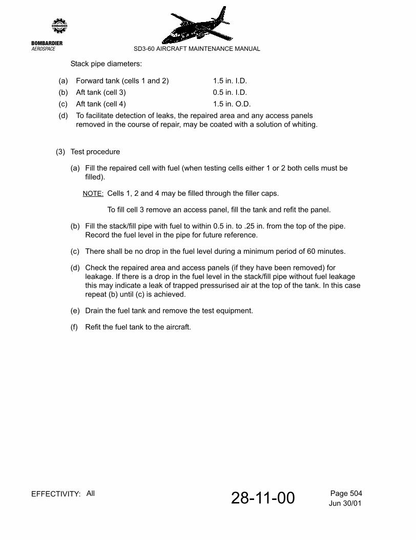
Stack pipe diameters:
(3) Test procedure
(a) Fill the repaired cell with fuel (when testing cells either 1 or 2 both cells must be filled).
NOTE: Cells 1, 2 and 4 may be filled through the filler caps.
To fill cell 3 remove an access panel, fill the tank and refit the panel.
(b) Fill the stack/fill pipe with fuel to within 0.5 in. to .25 in. from the top of the pipe. Record the fuel level in the pipe for future reference.
(c) There shall be no drop in the fuel level during a minimum period of 60 minutes.
(d) Check the repaired area and access panels (if they have been removed) for leakage. If there is a drop in the fuel level in the stack/fill pipe without fuel leakage this may indicate a leak of trapped pressurised air at the top of the tank. In this case repeat (b) until (c) is achieved.
(e) Drain the fuel tank and remove the test equipment.
(f) Refit the fuel tank to the aircraft.
(a) Forward tank (cells 1 and 2) 1.5 in. I.D.(b) Aft tank (cell 3) 0.5 in. I.D.(c) Aft tank (cell 4) 1.5 in. O.D.(d) To facilitate detection of leaks, the repaired area and any access panels
removed in the course of repair, may be coated with a solution of whiting.
Jun 30/0128-11-00 Page 505EFFECTIVITY: All
zSD3-60 AIRCRAFT MAINTENANCE MANUAL
In-situ Pressure Testing of Fuel TanksFigure 501
Jun 30/0128-12-00 Page 1EFFECTIVITY: All
zSD3-60 AIRCRAFT MAINTENANCE MANUAL
AMM28-12-00 7.0.0.0TANK VENT SYSTEM - DESCRIPTION/OPERATION
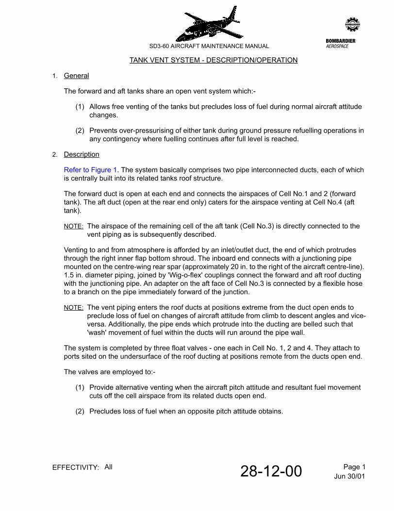
1. General
The forward and aft tanks share an open vent system which:-
(1) Allows free venting of the tanks but precludes loss of fuel during normal aircraft attitude changes.
(2) Prevents over-pressurising of either tank during ground pressure refuelling operations in any contingency where fuelling continues after full level is reached.
2. Description
Refer to Figure 1. The system basically comprises two pipe interconnected ducts, each of which is centrally built into its related tanks roof structure.
The forward duct is open at each end and connects the airspaces of Cell No.1 and 2 (forward tank). The aft duct (open at the rear end only) caters for the airspace venting at Cell No.4 (aft tank).
NOTE: The airspace of the remaining cell of the aft tank (Cell No.3) is directly connected to the vent piping as is subsequently described.
Venting to and from atmosphere is afforded by an inlet/outlet duct, the end of which protrudes through the right inner flap bottom shroud. The inboard end connects with a junctioning pipe mounted on the centre-wing rear spar (approximately 20 in. to the right of the aircraft centre-line). 1.5 in. diameter piping, joined by 'Wig-o-flex' couplings connect the forward and aft roof ducting with the junctioning pipe. An adapter on the aft face of Cell No.3 is connected by a flexible hose to a branch on the pipe immediately forward of the junction.
NOTE: The vent piping enters the roof ducts at positions extreme from the duct open ends to preclude loss of fuel on changes of aircraft attitude from climb to descent angles and vice-versa. Additionally, the pipe ends which protrude into the ducting are belled such that 'wash' movement of fuel within the ducts will run around the pipe wall.
The system is completed by three float valves - one each in Cell No. 1, 2 and 4. They attach to ports sited on the undersurface of the roof ducting at positions remote from the ducts open end.
The valves are employed to:-
(1) Provide alternative venting when the aircraft pitch attitude and resultant fuel movement cuts off the cell airspace from its related ducts open end.
(2) Precludes loss of fuel when an opposite pitch attitude obtains.
Jun 30/0128-12-00 Page 2EFFECTIVITY: All
zSD3-60 AIRCRAFT MAINTENANCE MANUAL
Tank Vent SystemFigure 1
Jun 30/0128-20-00 Page 1EFFECTIVITY: All
zSD3-60 AIRCRAFT MAINTENANCE MANUAL
AMM28-20-00 8.0.0.0DISTRIBUTION - GENERAL
1. General
This sub-section provides detailed information on:-
(1) System replenishment and drainage
(2) The fuel feed from the tanks to the engines
Replenishment and drainage is afforded by a pressure refuel/defuel system. Refer to 28-21-00, pb1. The refuel/defuel coupling is mounted on a servicing panel in the right main landing gear fairing - the aft cone of which hinges open to expose the panel.
NOTE: Alternatively, replenishment and system drainage may respectively be accomplished by gravity feed through filler caps on top of tank Cells 1, 2 and 4 and through system drain valves positioned below each collector tank.
The left and right engines are normally fed from the forward and aft roof tanks respectively via booster pumps housed within gravity - fed collector tanks mounted in the fuselage right sidewall. The system incorporates a 'crossfeeding' facility. Refer to 28-22-00, pb1.
Dec 18/0728-20-01 Page 201EFFECTIVITY: All
zSD3-60 AIRCRAFT MAINTENANCE MANUAL
AMM28-20-01 1.0.0.0FUEL SYSTEM PIPEWORK - MAINTENANCE PRACTICES
1. General
WARNING: THIS MAINTENANCE PROCEDURE IS RELATED TO THE FUEL TANK SAFETY PROGRAMME AND INCORRECT MAINTENANCE COULD ADVERSELY AFFECT THE DESIGN STANDARDS OF THE FUEL TANK SYSTEM. STRICT ADHERENCE TO THE PROCEDURES IN THIS SECTION IS THEREFORE RECOMMENDED.
Bonding leads disturbed during the removal procedures for pipework are to be re-attached and tested at a convenient stage during the installation procedure, in accordance with standard practices. Refer to 20-09-05, pb201.
Do an internal inspection of the fuel tank before it is refueled, in accordance with standard practices. Refer to 20-09-12, pb201.
Jun 30/0128-21-00 Page 1EFFECTIVITY: All
zSD3-60 AIRCRAFT MAINTENANCE MANUAL
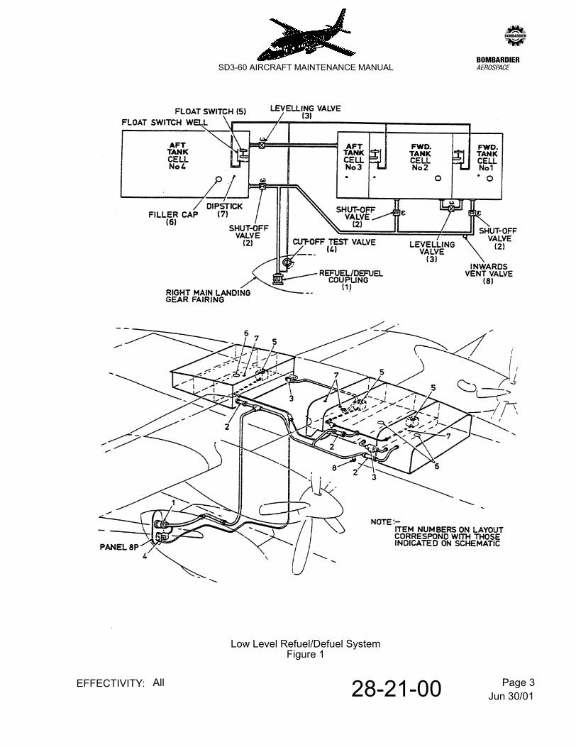
AMM28-21-00 9.0.0.0LOW LEVEL REFUEL/DEFUEL SYSTEM - DESCRIPTION OPERATION
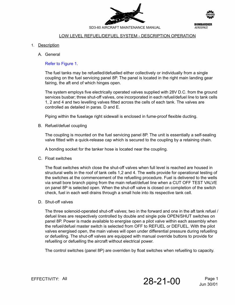
1. Description
A. General
Refer to Figure 1.
The fuel tanks may be refuelled/defuelled either collectively or individually from a single coupling on the fuel servicing panel 8P. The panel is located in the right main landing gear fairing, the aft end of which hinges open.
The system employs five electrically operated valves supplied with 28V D.C. from the ground services busbar; three shut-off valves, one incorporated in each refuel/defuel line to tank cells 1, 2 and 4 and two levelling valves fitted across the cells of each tank. The valves are controlled as detailed in paras. D and E.
Piping within the fuselage right sidewall is enclosed in fume-proof flexible ducting.
B. Refuel/defuel coupling
The coupling is mounted on the fuel servicing panel 8P. The unit is essentially a self-sealing valve fitted with a quick-release cap which is secured to the coupling by a retaining chain.
A bonding socket for the tanker hose is located near the coupling.
C. Float switches
The float switches which close the shut-off valves when full level is reached are housed in structural wells in the roof of tank cells 1,2 and 4. The wells provide for operational testing of the switches at the commencement of the refuelling procedure. Fuel is delivered to the wells via small bore branch piping from the main refuel/defuel line when a CUT OFF TEST VALVE on panel 8P is selected open. When the shut-off valve is closed on completion of the switch check, fuel in each well drains through a small hole into its respective tank cell.
D. Shut-off valves
The three solenoid-operated shut-off valves; two in the forward and one in the aft tank refuel /defuel lines are respectively controlled by double and single pole OPEN/SHUT switches on panel 8P. Power is made available to energise open a pilot valve within each assembly when the refuel/defuel master switch is selected from OFF to REFUEL or DEFUEL. With the pilot valves energised open, the main valves will open under differential pressure during refuelling or defuelling. The shut-off valves are equipped with manual override buttons to provide for refuelling or defuelling the aircraft without electrical power.
The control switches (panel 8P) are overriden by float switches when refuelling to capacity.
Jun 30/0128-21-00 Page 2EFFECTIVITY: All
zSD3-60 AIRCRAFT MAINTENANCE MANUAL
E. Levelling valves
The motorised-ball type levelling valves are controlled by the master switch on panel 8P. Selection of the switch to REFUEL or DEFUEL will open both valves. The valves may also be operated by a single OPEN/SHUT switch on the flight compartment roof panel 4P when the master switch is set to OFF which:-
(a) affords the pilot a pre-flight levelling facility and
(b) permits opening of the valves for gravity refuelling without reference to the servicing panel.
Indicator modules which form part of the line diagram on panels 4P and 8P display line indication of levelling valve settings; that on 4P for the AFT TANK is integral with the pilots levelling valve control switch.
2. Operation
With power from the 28V d.c. ground services busbar available, setting of the master switch on the fuel servicing panel 8P from OFF to REFUEL or DEFUEL will:-
(a) open the tank inter-cell levelling valves and
(b) make power available for actuation of the solenoid-operated shut-off valves in the refuel/defuel lines.
The solenoids are energised when their appropriate control switches on panel 8P are selected OPEN.
The shut-off valves remain open during refuelling until selected OFF at the control switch or de-energised closed through the float switches which override the control switches when full level is reached.
When refuelling to full level, the float switches are confirmed operational by opening a test valve on the servicing panel at commencement of refuelling. This permits some of the tanker supply to enter wells in which the float switches are housed. A very substantial reduction in the tankers indicated flow rate will prove that the shut-off valves have closed and that the float switches are serviceable. When this occurs, the test valve is closed, the wells drain to respective cells, the shut-off valves re-open and refuelling continues until operational float switch action occurs.
The float switches, one in each of cells 1, 2 and 4 and the open levelling valves which interconnect cells 1 and 2 (forward tank) and 3 and 4 (aft tank) monitor the maximum achievable fuel contents of the tanks. During pressure refuelling the float switches operate on rising fuel levels to de-energise the solenoid operated shut-off valves.
When the float switch in cell 1 operates it closes both shut-off valves leading to cells 1 and 2, whilst the float switch in cell 2 controls only its own shut-off valve.
Jun 30/0128-21-00 Page 3EFFECTIVITY: All
zSD3-60 AIRCRAFT MAINTENANCE MANUAL
Low Level Refuel/Defuel SystemFigure 1
Jun 30/0128-21-00 Page 4EFFECTIVITY: All
zSD3-60 AIRCRAFT MAINTENANCE MANUAL
After the shut-off valves have closed, the tanker is selected to suction and fuel trapped between the valves and the refuel/defuel coupling is drawn-off (an inwards vent valve in the line permits air to enter as the fuel is extracted).
During defuelling operations, the tank float switches are electrically by-passed via the master switch, thus permitting the shut-off valves leading to cell 1 in the forward tank and cell 4 in the aft tank to be opened even if the tanks are at full level.
The shut-off valve leading to cell 2 remains closed during defuelling operations in order to prevent air being extracted due to differing levels of the shut-off valves in cells 1 and 2 in the forward tank.
Dec 18/0728-21-01 Page 201EFFECTIVITY: All
zSD3-60 AIRCRAFT MAINTENANCE MANUAL
AMM28-21-01 1.0.0.0FUEL TANK LEVELLING VALVES - MAINTENANCE PRACTICES
WARNING: THIS MAINTENANCE PROCEDURE (OR PART THEREOF) IS RELATED TO THE FUEL TANK SAFETY PROGRAMME AND INCORRECT MAINTENANCE COULD ADVERSELY AFFECT THE DESIGN STANDARDS OF THE FUEL TANK SYSTEM. STRICT ADHERENCE TO THE PROCEDURES IN THIS SECTION IS THEREFORE RECOMMENDED.
1. Removal/Installation
Refer to Figure 201.
A. Forward tank levelling valve
Bonding leads freed during removal operations are to be re-attached and tested at a convenient stage during the installation procedure in accordance with standard practice. Refer to 20-09-05, pb1 and Refer to 20-09-05, pb201.
(1) Remove a unit
(a) Drain forward fuel tank (cells No.1 & 2). Refer to 12-10-28, pb301.
(b) Isolate electrical supply by opening C/B No. 253 on distribution panel 2D.
(c) Remove access panel 240FR on forward fairing. Refer to 6-30-00, pb1.
(d) Remove electrical plug from unit.
(e) Unscrew eight bolts and washers from pipe flange which is attaching pipe to tank cell No.2.
(f) Remove gasket and discard.
(g) Unscrew forward pipe coupling from unit.
(h) Unscrew bolt and washer from restraining plate to release unit and aft pipe.
(i) Lift unit and aft pipe clear.
(j) Remove 'O' ring from end of forward pipe and discard.
(k) Blank off all pipe connections.
(2) Install a unit
NOTE: Steps (a) and (b) only apply if unit is not that previously removed (para. A.).
(a) Remove aft pipe with 'O' ring from unserviceable unit. Discard 'O' ring.
Dec 18/0728-21-01 Page 202EFFECTIVITY: All
zSD3-60 AIRCRAFT MAINTENANCE MANUAL
(b) Fit pipe to replacement unit using new 'O' ring Pt.No. MS29513-329 and hand tighten pipe coupling.
(c) Offer unit up to forward pipe (i.e. existing on aircraft). Remove blank and fit new 'O' ring Pt.No. MS29513-329 and hand tighten pipe coupling.
(d) Remove blank and fit new gasket Pt.No. SD3-57-0350 to pipe flange.
(e) Remove blank from tank and fit pipe flange with gasket to tank cell No.2 using eight bolts and washers. Tighten bolts.
(f) Align tapped hole in unit with hole in restraining plate and fit bolt with washer. Apply 'LOCKTITE GRADE A' to threads and tighten.
(g) Torque tighten pipe couplings to 32 +0 lb.ft. and witness mark. Refer to 20-09-04, pb1.
(h) Install electrical plug to unit.
WARNING: START OF FUEL TANK SAFETY CRITICAL SECTION.
(i) Do an internal visual inspection of the fuel tank before it is refueled, in accordance with standard practices. Refer to 20-09-12, pb201.
WARNING: END OF FUEL TANK SAFETY CRITICAL SECTION.
(j) Refuel the forward tank. Refer to 12-10-28, pb301.
(k) Install access panel 240FR on forward fairing. Refer to 6-30-00, pb1.
(l) Energise electrical supply to unit by closing C/B No. 253 on distribution panel 2D.
B. Aft tank levelling valve
NOTE: Bonding leads freed during removal operations are to be re-attached and tested at a convenient stage during installation in accordance with standard practice. Refer to 20-09-05, pb1 and Refer to 20-09-05, pb201.
(1) Remove a unit.
(a) Drain aft fuel tank (cells No.3 and 4). Refer to 12-10-28, pb301.
(b) Isolate electrical supply by opening C/B No. 253 on distribution panel 2D.
(c) Remove access panels 240ML and 250AL on fairing. Refer to 6-30-00, pb1.
(d) Remove electrical plug from unit.
(e) Unscrew pipe couplings from unit.
Dec 18/0728-21-01 Page 203EFFECTIVITY: All
zSD3-60 AIRCRAFT MAINTENANCE MANUAL
(f) Remove the three pipe clamp assemblies immediately forward of the unit to ease removal.
(g) Unscrew two bolts and washers from restraining plate to release unit.
(h) Remove unit.
(i) Remove 'O' rings from end of pipes and discard.
(j) Blank off pipes and connections on unit.
(2) Install a unit
(a) Remove blanks from pipes and fit new 'O' rings Pt.No. MS29513-329.
(b) Remove blanks from unit and offer it up to pipes and hand tighten couplings.
(c) Align tapped holes in unit with holes in restraining plate and fit bolts and washers. Apply 'LOCKTITE GRADE A' to threads and tighten.
(d) Torque tighten pipe couplings to 32 +0 -3 lb.ft and witness mark. Refer to 20-09-04, pb1.
(e) Install three pipe clamp assemblies immediately forward of the unit.
(f) Install electrical plug in unit.
WARNING: START OF FUEL TANK SAFETY CRITICAL SECTION.
(g) Do an internal visual inspection of the fuel tank before it is refueled, in accordance with standard practices. Refer to 20-09-12, pb201.
WARNING: END OF FUEL TANK SAFETY CRITICAL SECTION.
(h) Refuel the aft tank. Refer to 12-10-28, pb301.
(i) Install access panels 240 ML and 250 AL on fairing. Refer to 6-30-00, pb1.
(j) Energise electrical supply to unit closing C/B No.253 on distribution panel 2D.
WARNING: THIS MAINTENANCE PROCEDURE (OR PART THEREOF) IS A FUEL TANK SAFETY CRITICAL ITEM, AND RELATES TO A CRITICAL DESIGN CONFIGURATION CONTROL LIMITATION (CDCCL) DEFINED BY THE AIRCRAFT OEM (REFER TO 5-20-02, PB1).THE CONTENTS OF THIS PROCEDURE MUST BE STRICTLY ADHERED TO AND MUST NOT BE ALTERED TO ENSURE THAT UNSAFE CONDITIONS DO NOT DEVELOP BY MAINTENANCE, MODIFICATION OR REPAIR.
1. Removal/Installation
A. Remove a float switch
Refer to 12-10-28, Figure 301, for float switch location.
(1) Drain the fuel tank of the associated float switch to be removed. Refer to 12-10-28, pb301.
WARNING: ENSURE THAT ALL FIRE PRECAUTIONS DETAILED IN REFER TO 28-11-00, PB401, ARE OBSERVED WHEN WORKING INSIDE FUEL TANKS.
(2) Gain access to the associated float switch by removing the following access panels. Refer to 6-30-00, pb1:-
(a) Cell No.1 (Fwd tank) - 240GL
(b) Cell No.2 (Fwd tank) - 240JL
(c) Cell No.4 (Aft Tank) - 250EL
(3) Disconnect the associated electrical socket connection at the following position:-
(a) Cells 1 and 2 - left side of forward tank
(b) Cell 4 - forward face of aft tank
(4) Remove and discard lockwire from the jam nut, remove jam nut from the receptacle and withdraw receptacle through the housing in the fuel tank wall.
NOTE: Install jam nut on the receptacle for retainment.
(5) Disconnect the cable securing clip(s) from the tank structure, retaining the bolt(s) and washer(s).
(6) Disconnect the five bolts and washers securing the external portion of the float switch to the structural well housing.
(7) Support the float switch, and carefully manoeuvre the internal portion through the opening in the housing.
Dec 18/0728-21-21 Page 202EFFECTIVITY: All
zSD3-60 AIRCRAFT MAINTENANCE MANUAL
(8) Retain blanking plate and discard the gasket subsequently removed with the float switch.
WARNING: START OF FUEL TANK CRITICAL SECTION.
WARNING: FIELD MAINTENANCE OF THE FLOAT SWITCH IS NOT PERMISSIBLE. THERE ARE INTERNAL DESIGN FEATURES WHICH ARE CRITICAL TO FUEL TANK SAFETY. THE UNIT MUST BE MAINTAINED IN ACCORDANCE WITH THE ORIGINAL EQUIPMENT MANUFACTURER (OEM) OVERHAUL MANUAL (SECTION 28-41-65), BY APPROPRIATELY APPROVED MAINTENANCE ORGANISATIONS.
WARNING: END OF FUEL TANK CRITICAL SECTION.
B. Install a float switch
(1) If required, do an insulation resistance bench test between each switch connector pin and the switch mounting flange. Refer to 20-09-05, pb201.
(2) Fit the blanking plate and replacement gasket Pt.No. SD3-56-0262 onto the float switch prior to installation.
(3) Support the float switch and carefully manoeuvre the internal portion through the housing opening in the well structure.
(4) Align the blanking plate and gasket holes along with those of the external portion of the float switch to receive the securing attachments.
(5) Connect the float switch to the well housing structure with the five washers and bolts.
(6) Connect the cable securing clip to the tank structure with the washer and bolt.
(7) Remove the jam nut retained on the receptacle, insert the receptacle in the fuel tank housing and attach with the jam nut.
(8) Torque tighten the jam nut in accordance with chapter 20-09-07, pb1.
(9) Secure the jam nut with lockwire in accordance with chapter 20-09-10, pb1.
(10) Connect the associated electrical socket connection.
WARNING: START OF FUEL TANK CRITICAL SECTION.
(11) Do an internal visual inspection of the fuel tank before it is refueled, in accordance with standard practices. Refer to 20-09-12, pb201.
WARNING: END OF FUEL TANK CRITICAL SECTION.
(12) Refit the associated access panel retained from the removal procedure.
(13) Refuel the tank and check that the float switch operates. Refer to 12-10-28, pb301.
Jun 30/0128-22-00 Page 1EFFECTIVITY: All
zSD3-60 AIRCRAFT MAINTENANCE MANUAL
AMM28-22-00 11.0.0.0FUEL FEED - DESCRIPTION AND OPERATION
1. Description
A. General
Refer to Figure 1.
The fuel feed from the forward tank (fuel Cells 1 and 2) to the left engine is similar to that of the aft tank (fuel Cells 3 and 4) to the right engine.
Fuel is gravity fed from a tank, through non-return valves and an isolation valve to a collector tank in the fuselage right sidewall. A booster pump in each collector tank pumps fuel through a filter and non-return valve to the appropriate of two T-pieces introduced in the common line which crosses the forward face of the centre wing front spar between two L.P. fuel control valves. A crossfeed valve, connected between the T-pieces normally segregates the two engine supply lines. The valve is opened operationally in circumstances detailed in para 2.
Piping from the output connection on each L.P. valve is routed into the associated wing where it runs between the spars to a T-piece situated immediately inboard of rib station 106.5. The aft end of the T-piece is fitted with a pressure switch. The pressure switch is incorporated to provide warning of booster pump failure. Refer to 28-41-00, pb1.
NOTE: Post-mod 7481, the pressure switch is manifold-attached to the T-piece together with a relief valve which off-loads post engine shutdown residual pressure in the supply line back to tank (para G refers).
Piping from the forward connection of each T-piece is routed through the wing front spar to a connector on the landing edge riblet immediately inboard of the engine. Beyond the connector fuel is supplied via a flexible delivery hose to the engines fuel heater.
Refer to 28-21-00, pb1. To prevent air from being trapped in the collector tanks during replenishment - vent lines fitted to the top of each are routed up the sidewall and thence to the air spaces within the roof tanks. The forward and aft collector tanks are respectively vented to fuel Cells 1 and 3.
NOTE: Each vent line incorporates a negative 'g' valve which is normally open - thus filling the vent lines with fuel to the highest level obtaining in the system. The valves function is detailed in para C.
Two system drain valves (para F) provide for water checking and total drainage of the system.
System pipes which run within the fuselage sidewall (apart from those within the sealed collector tank compartments) are encased in flexible fume-proof ducting.
Jun 30/0128-22-00 Page 2EFFECTIVITY: All
zSD3-60 AIRCRAFT MAINTENANCE MANUAL
B. Collector tanks]
The collector tanks are located to provide an uninterrupted fuel supply to the engines with low fuel contents and maximum attitude changes. The forward and aft tanks are identical and are housed in externally accessible sealed compartments in the fuselage right sidewall between frames stations 175 to 197 and 351 to 376 respectively.
A tank basically consists of an upright rectangular box manufactured from welded light alloy sheets and pressings. The tank is radiused on all edges and has a capacity of 0.9 Imp. Gal.
The top and bottom surfaces are fitted with identical pipe unions which respectively provide for attachment of vent and drain piping.
A small, right-angled fuel inlet pipe, flange-jointed to the aft side of the tank connects to the gravity feed isolation valve (para F).
A machined booster pump mounting ring, fitted with six anchor nuts, is welded to the pump installation opening in the forward face of the tank. The inner radius of the ring is chamfered to provide a seat for the pump installation seal.
Tank attachment is by means of four bolts, washers and stiffnuts (two top and two bottom) which secure attachment angles on the tanks top and bottom surfaces to two channels which run across the back panel of the sealed compartment.
C. Negative 'g' valves
These valves (introduced, one in each collector tanks vent line) are employed to ensure sufficient fuel is available under negative 'g' conditions for not less than 10 seconds operation of the engines.
Each valve consists of a double-ended pipe union, the small diameter end of which screws into a sleeve coupling. The assembly, which is sealed by an O-ring, houses a steel ball. The ball normally seats on the bore of the union thus allowing free passage of fuel or air (dependent upon the level of fuel in the system) through four circumferentially pitched holes in the union below the ball seat.
If negative 'g' conditions are encountered in flight - the ball unseats to seal off the upper bore in the sleeve coupling, thus effectively retaining sufficient fuel in the associated collector tank to allow for not less than ten seconds of engine operation.
D. Booster pumps
The booster pumps, idented 1QA3 (left engine supply) and 2QA3 (right engine supply) are respectively housed in the forward and aft collector tanks.
Each pump is driven by a capacitor start, single phase A.C. motor. Control is by means of two ON/OFF switches which are subject to the overriding authority of circuit breakers; the switches are mounted on the fuel section of flight compartment roof panel 4P and the circuit breakers on the left and right distribution panels 1D and 2D respectively.
Jun 30/0128-22-00 Page 3EFFECTIVITY: All
zSD3-60 AIRCRAFT MAINTENANCE MANUAL
E. Filters
The Janitrol manufactured fuel filters (Pt.No.52-2145-022) are of the 'T' configuration type. The unit incorporates a by-pass valve, a differential pressure switch and a cleanable, 70 micron barrier - type filter element.
The by-pass valve opens automatically when the pressure differential exceeds a certain level. The differential pressure switch provides warning of impending by-pass action. Refer to 28-44-00, pb1.
A spring-loaded water drain button is provided at the base of the unit.
F. Manually operated valves
The manually-operated valves throughout the system are identical. The units (Pt.No.7913101/F) are supplied by Flight Refuelling Ltd. and are employed as follows:-
(1) L.P. fuel valve
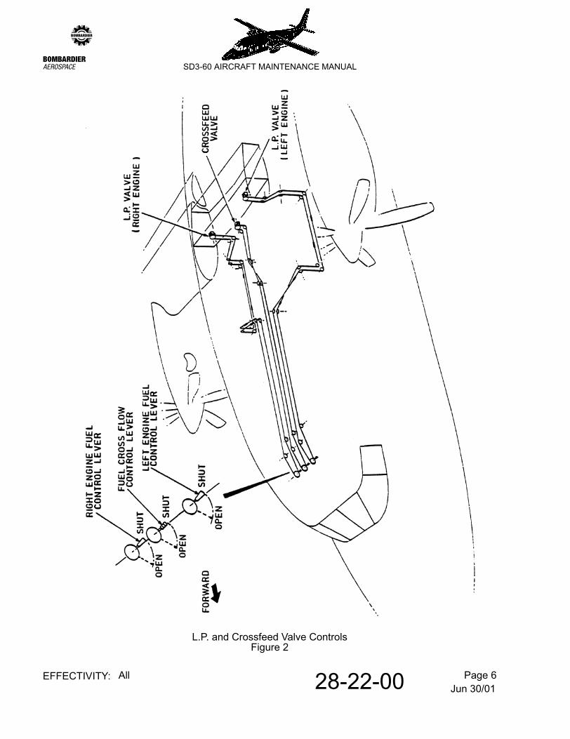
The two L.P. fuel control valves are mounted on the centre wing front spar at positions 30 in. on each side of the centre-line. Each is fitted with a splined pulley which is cable operated from a control lever on the flight compartment roof console.
The control levers, which are panel idented LEFT L.P. VALVE and RIGHT L.P. VALVE each operate within a two-position gate (OPEN-forward, SHUT-aft).
NOTE: To prevent inadvertent closure, the levers are each lashed by a securing wire in the open position. The securing wire is breakable in an emergency.
(2) Crossfeed valve
The crossfeed valve is mounted on the right side of the wing front spar. In like-manner to the L.P. valves, the unit is fitted with a splined pulley which is cable-operated from a control lever on the flight compartment roof console.
The control lever is panel idented CROSSFEED VALVE and operates within a two-position gate (OPEN-forward, SHUT-aft).
(3) Isolation valves
An isolation valve, fitted with a splined operating handle, is located in each collector tank compartment (in the gravity feed line immediately upstream of the tank).
The valves, which are normally set open (system operational) are provided to enable the collector tanks to be isolated to allow servicing operations to be performed on the booster pumps without total drainage of the associated system.
NOTE: A locking bracket on each compartment access panel renders it impossible to close the panel with the valve inadvertently set closed.
Jun 30/0128-22-00 Page 4EFFECTIVITY: All
zSD3-60 AIRCRAFT MAINTENANCE MANUAL
Fuel Feed SystemFigure 1
Jun 30/0128-22-00 Page 5EFFECTIVITY: All
zSD3-60 AIRCRAFT MAINTENANCE MANUAL
(4) System drain valves
Two system drain valves (fitted with splined operating handles) are provided. They are positioned in small externally accessible compartments located immediately forward of frame stations 197 to 376 in the fuselage right sidewall (approximately three feet above the aircraft water line O").
Piping to each valve is routed down the sidewall from a connector on the bottom of its associated collector tank. A short open-ended pipe connected to the valve outlet provides for the attachment of a suitable drain hose.
G. Residual pressure relief arrangement
NOTE: This is embodied on aircraft Ser.Nos.SH3638 and subsequent by Mod 7481 and on those prior construction numbers on which Serv.Bull.SD360-28-03 is incorporated.
Refer to Figure 3. Post-shutdown residual pressure in the supply line to an engine is off-loaded to tank by a relief valve which is interposed in a pipe which links the fuel supply to the FCU air purge line (operationally downstream of the purge valve).
The relief valve, Lee Products Pt.No.PRLX 0501300A opens at 60 psi.
2. Operation
Under all normal flight conditions including take-off and landing, each engine is supplied from its normally associated tank, i.e. booster pumps running-crossfeed valve closed.
The crossfeed valve which segregates the two engine supply lines is only operationally opened to:-
(a) permit balanced use of both tanks subsequent to an engine failure by alternating use of the booster pumps and
(b) should engine malfunction occur whilst operating on suction (booster pump failed)
Should one or both booster pumps fail, warning will be given by the illumination of appropriate warning lights on panel 1P.
NOTE: The performance of the engine-driven pumps is sufficient to maintain fuel flow on booster pump failure up to an altitude of 20000 ft.
In the event of a power plant fire, the L.P. valve on that side must be closed to shut off fuel supply to that engine after the fuel condition and R.P.M. levers (centre console) have been moved to their most rearward positions to shut down the engine and feather the propeller.
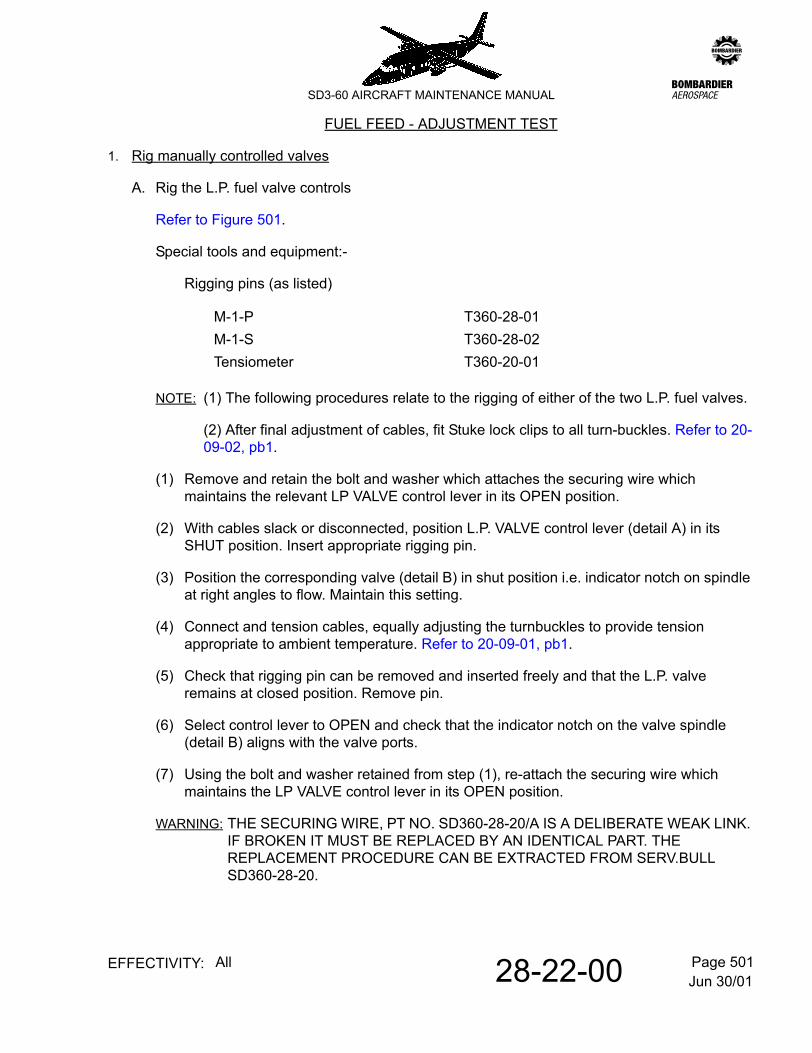
NOTE: (1) The following procedures relate to the rigging of either of the two L.P. fuel valves.
(2) After final adjustment of cables, fit Stuke lock clips to all turn-buckles. Refer to 20-09-02, pb1.
(1) Remove and retain the bolt and washer which attaches the securing wire which maintains the relevant LP VALVE control lever in its OPEN position.
(2) With cables slack or disconnected, position L.P. VALVE control lever (detail A) in its SHUT position. Insert appropriate rigging pin.
(3) Position the corresponding valve (detail B) in shut position i.e. indicator notch on spindle at right angles to flow. Maintain this setting.
(4) Connect and tension cables, equally adjusting the turnbuckles to provide tension appropriate to ambient temperature. Refer to 20-09-01, pb1.
(5) Check that rigging pin can be removed and inserted freely and that the L.P. valve remains at closed position. Remove pin.
(6) Select control lever to OPEN and check that the indicator notch on the valve spindle (detail B) aligns with the valve ports.
(7) Using the bolt and washer retained from step (1), re-attach the securing wire which maintains the LP VALVE control lever in its OPEN position.
WARNING: THE SECURING WIRE, PT NO. SD360-28-20/A IS A DELIBERATE WEAK LINK. IF BROKEN IT MUST BE REPLACED BY AN IDENTICAL PART. THE REPLACEMENT PROCEDURE CAN BE EXTRACTED FROM SERV.BULL SD360-28-20.
Pressurised air supply (with shut-off valve control)
Water manometer
(1) Remove passenger compartment furnishing panels, sufficient to provide access to fuel pipe shrouds.
(2) Seal the aft collector tank door and the aft FUEL DRAIN door using insulating tape.
(3) Attach a water manometer to the pipe in the aft FUEL DRAIN door.
(4) Connect the pressurised air supply to the eductor pipe adjacent to the aft collector tank.
(5) Open the shut-off valve until a pressure of 3 in. to 6 in. is indicated on the manometer.
(6) Apply bubble solution to all fuel shroud joints and structural components i.e. collector tank and FUEL DRAIN compartments.
NOTE: Leaks in the structural components should be sealed with 'Bostik' PR1221 and leaks at the shroud junctions, sealed by tightening the jubilee clip.
(7) Repeat paras (2) to (6) for the forward fuel system.
(8) Refit interior access panels and disconnect equipment.
Jun 30/0128-22-00 Page 505EFFECTIVITY: All
zSD3-60 AIRCRAFT MAINTENANCE MANUAL
Crossfeed Valve Control - RiggingFigure 502
Jun 30/0128-22-00 Page 506EFFECTIVITY: All
zSD3-60 AIRCRAFT MAINTENANCE MANUAL
3. Fuel Cells - Fuel flow check
NOTE: (1) The following procedure confirms that fuel flow to each collector tank is available from both of its associated fuel cells. The procedure for the relevant cells is to be carried out following restoration of any breakdown of the gravity feed system.
(2) Ensure the aircraft is level, the levelling valves are CLOSED and both fuel tanks have been drained to the undrainable level (it is essential that the levelling valve between Cell 3 and Cell 4 of the aft tank is CLOSED before draining the aft tank and remains closed for the duration of the tests - refer to para. B.(5), note).
(3) The forward tank and aft tank can be treated as separate systems, therefore, flow tests on each tank can be performed simultaneously.
A. Forward tank (Cells 1 and 2)
NOTE: The sequence in performing the following checks is unimportant.
(1) Check that the system drain valve and levelling valve are closed.
(2) Remove Cell 1 filler cap and load 15 gallons of fuel.
(3) Open the system drain valve and drain the fuel in Cell 1 into a suitable clean container. Check that the quantity of fuel drained is 15 gallons.
(4) Repeat paras (1) to (3) inclusive for Cell 2. Visually check that no fuel has transferred into Cell 1.
(5) Close the system drain valve and refit filler caps.
B. Aft tank (Cell 3)
(1) Check that the system drain valve is closed.
(2) Remove dipstick from Cell 3, and using a suitable funnel load 5 gallons of fuel into Cell 3, via the dipstick aperture.
(3) Remove funnel and fit dipstick.
(4) Check that there is no fuel in Cell 4.
(5) Open the system drain valve and drain the fuel in Cell 3 into a suitable clean container. Check that the quantity of fuel drained is 5 gallons.
NOTE: If Cell 3 was empty prior to closing the levelling valves a quantity of fuel will be used to fill the levelling pipe i.e. a maximum of 1 gallon, therefore, leaving a minimum of 4 gallons which is drainable.
(6) Close the system drain valve.
Jun 30/0128-22-00 Page 507EFFECTIVITY: All
zSD3-60 AIRCRAFT MAINTENANCE MANUAL
C. Aft tank (Cell 4)
(1) Check that the system drain valve is closed.
(2) Remove Cell 4 filler cap and load 15 gallons of fuel.
(3) Open the system drain valve and drain the fuel in Cell 4 into a suitable clean container. Check that the quantity of fuel drained is 15 gallons.
(4) Close the system drain valve and refit filler cap.
Jun 30/0128-22-00 Page 601EFFECTIVITY: All
zSD3-60 AIRCRAFT MAINTENANCE MANUAL
AMM28-22-00 13.0.0.0FUEL FEED - INSPECTION/CHECK
1. Check rigging of manually controlled valves
A. Check L.P. fuel valve rigging.
Special tools and equipment:-
(1) Refer to 28-22-00, Figure 501 Remove and retain the bolt and washer which attaches the securing wire which maintains the left LP VALVE control lever in its OPEN position; move control lever to its aft SHUT position (detail A).
(2) Insert rigging pin M-1-P.
(3) Open access panel 240ML (left) on fuselage roof forward of wing front spar.
(4) Refer to 28-22-00, Figure 502 Check that indicator notch on spindle of L.P. valve is at right angles to fuel flow. (detail B).
(5) Check that rigging pin can be removed and inserted freely and that L.P. valve remains at closed position.
(6) Check that cable tension is appropriate to ambient temperature (Refer to 20-09-01, pb1.).
(7) Remove rigging pin M-1-P.
(8) Refer to 28-22-00, Figure 501 Select LP. VALVE control lever (roof console) to OPEN and check that indicator notch on the valve spindle aligns with the valve ports.
(9) Using the bolt and washer retained from step (1), re-attach the securing wire which maintains the LP VALVE control lever in its OPEN position.
WARNING: THE SECURING WIRE, PT NO. SD360-28-20/A IS A DELIBERATE WEAK LINK. IF BROKEN IT MUST BE REPLACED BY AN IDENTICAL PART. THE REPLACEMENT PROCEDURE CAN BE EXTRACTED FROM SERV. BULL. SD360-28-20.
(10) Close access panel 240ML.
(11) Repeat paras. (1) to (10) for right L.P. VALVE, using rigging pin M-1-S and opening access panel 240MR (right) on fuselage roof, forward of wing front spar.
Rigging pin M-1-P T360-28-01M-1-S T360-28-02
Tensiometer T360-20-01
Jun 30/0128-22-00 Page 602EFFECTIVITY: All
zSD3-60 AIRCRAFT MAINTENANCE MANUAL
B. Check crossfeed valve rigging
Special tools and equipment:-
(1) Refer to 28-22-00, Figure 502 Position CROSSFEED VALVE control lever (roof console) in its aft SHUT position (detail A).
(2) Insert rigging pin M-1-S.
(3) Open access panels 240NL and 240NR in fuselage roof, forward of wing front spar.
(4) Refer to 28-22-00, Figure 502 Check that indicator notch on spindle of crossfeed valve is at right angles to fuel flow (detail B).
(5) Check that rigging pin can be removed and inserted freely and that crossfeed valve remains at the closed position.
(6) Check that cable tension is appropriate to ambient temperature. Refer to 20-09-01, pb1.
(7) Remove rigging pin M-1-S.
(8) Refer to 28-22-00, Figure 502 Select CROSSFEED VALVE control lever (roof console) to OPEN and check that indicator notch on the valve spindle aligns with the valve ports (detail B).
WARNING: THIS MAINTENANCE PROCEDURE (OR PART THEREOF) IS RELATED TO THE FUEL TANK SAFETY PROGRAMME AND INCORRECT MAINTENANCE COULD ADVERSELY AFFECT THE DESIGN STANDARDS OF THE FUEL TANK SYSTEM. STRICT ADHERENCE TO THE PROCEDURES IN THIS SECTION IS THEREFORE RECOMMENDED.
1. Removal/Installation
Refer to Figure 201.
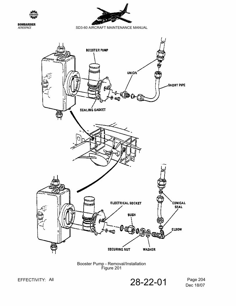
A. Remove a booster pump
(1) Remove appropriate access panels from fuselage side (230BR - forward collector tank, 230ER - aft collector tank, 230CR - forward drain valve and 230DR - aft drain valve). Refer to 6-30-00, pb1.
(2) Shut off the fuel supply to the collector tank by closing the isolation valve.
(3) Isolate electrical supply to booster pump by opening circuit breaker (CB) No.320 on distribution panel 1D for forward booster pump or CB No.370 on distribution panel 2D for aft booster pump.
(4) Connect a 3/4 in. diameter hose to the system drain valve, open the valve and drain the fuel in the collector tank into a container capable of holding 2 imp. gallons.
(5) Withdraw electrical socket from plug on pump mounting flange.
(6) Disconnect short pipe from top union, and from elbow (forward installation) or bottom union (aft installation). Discard conical seals.
(7) Remove six bolts and washers from pump mounting flange.
(8) Withdraw booster pump and sealing gasket.
B. Install a booster pump
Step (1) only applies if unit is not that previously removed (para. A).
(1) Remove and refit pump attachments as follows:-
(a) Forward pump - Slacken elbow securing nut, remove and discard 'O' ring and washer. Remove bush and discard 'O' ring. Refit bush to replacement pump along with new 'O' ring (Pt.No. MS29512-8). Attach new washer (Pt.No. MS28777-12) to elbow and refit to bush along with new 'O' ring (Pt.No. MS29512-12). Do not tighten securing nut at this stage.
Dec 18/0728-22-01 Page 202EFFECTIVITY: All
zSD3-60 AIRCRAFT MAINTENANCE MANUAL
(2) Install booster pump to collector tank, using a replacement sealing gasket (Pt.No. DIA83X3) if necessary, securing with six bolts and washers.
(3) Close system drain valve.
(4) Connect short pipe as follows and torque tighten. Refer to 20-09-04, pb1.
(5) Plug in electrical socket to plug on pump mounting flange.
(6) Open fuel isolation valve.
(7) Replace appropriate access panels on fuselage side (230BR - forward collector tank, 230ER - aft collector tank, 230CR - forward drain valve and 230DR - aft drain valve).
(8) Test pump operation (refer to para. 2.B.)
2. Adjustment/Test
WARNING: START OF FUEL TANK SAFETY CRITICAL SECTION.
WARNING: DO NOT RESET CIRCUIT BREAKER NO’s 320 OR 370 AS AN INITIAL TROUBLESHOOTING ACTION, IF THEY HAVE BEEN TRIPPED DURING FLIGHT. THERE IS POTENTIAL FOR ARCING IN AREAS THAT MAY CONTAIN FUEL VAPOUR.
BEFORE COMPLETING THIS SECTION, ENSURE THAT THE AIRCRAFT IS RENDERED ELECTRICALLY SAFE IN ACCORDANCE WITH 12-09-03, PB1.
A. Troubleshooting
(1) Visually check power wiring and connectors to the pump within the collector tank area.
(2) With the electrical connector disconnected from the pump, perform a continuity and insulation resistance check of the harnesses as follows:-
(a) Make sure that the associated booster pump switch is selected ON.
(b)Aft pump - Remove union and discard 'O' ring. Refit union to replacement pump along with new 'O' ring (Pt.No. MS29512-8).
(a) Forward installation - Connect to top union and elbow along with replacement conical seals (Pt.No. VSF1015A-12B). Tighten elbow securing nut.
(b) Aft installation - Connect to top and bottom unions along with replacement conical seals (Pt.No. VSF1015A-8B).
Dec 18/0728-22-01 Page 203EFFECTIVITY: All
zSD3-60 AIRCRAFT MAINTENANCE MANUAL
(b) Use a BM80/2 multi-meter (or equivalent) and select the continuity range setting.
(c) Complete a continuity test between the screen of the cable attached to pin ‘A’ of the disconnected pump connector (+ve probe) and a local ground point (-ve probe).
NOTE: The flylead connected to the screen may be an appropriate attachment point.
(d) Use a BM80/2 multi-meter (or equivalent) and select the 500 Vdc insulation resistance range setting.
(e) Check the insulation resistance between the points that follow:-
NOTE: The flylead connected to the screen may be an appropriate attachment point.
3 If the insulation resistance is less than 2 MOhm, identify and replace faulty cable section, if necessary by isolating and testing individual cables.
(3) If these checks are satisfactory and a faulty pump is suspected, then remove the pump (refer to para. 1.A.) and return to the pump manufacturer for internal fault investigation.
WARNING: END OF FUEL TANK SAFETY CRITICAL SECTION.
B. Test operation
(1) Energise appropriate busbars. Refer to 12-09-03, pb301.
(2) Provide electrical supply to booster pump by closing CB No.320 on distribution panel 1D for forward booster pump or close CB No.370 on distribution panel 2D for aft booster pump.
(3) Check that CB No.16 on distribution panel 1D and CB No.166 on distribution panel 2D are closed to energize electrical supply to fuel pressure switches.
(4) Check that FUEL PRESS L AND FUEL PRESS R amber lights on pilots instrument panel 1P are illuminated.
(5) Select appropriate LP VALVE control lever to OPEN position.
(6) Select BOOSTER PUMP switch on panel 4P to ON.
(7) Check that appropriate FUEL PRESSURE amber light is extinguished.
(1) Remove appropriate access panels from fuselage side and fairing (230BR forward isolation valve and 240RR forward fuel filter or 230ER aft isolation valve and 250DR aft fuel filter). Refer to 6-30-00, pb1.
(2) Shut off the fuel supply by closing the isolation valve.
(3) Remove filter element, clean as detailed in para 4.A.
(4) Remove and discard the fuel filter head 'O' ring, check that 'O' ring groove is clean.
(5) Fit cleaned or replacement element with new 'O' ring Pt.No. MS29513-140.
(6) Open fuel isolation valve.
(7) Refer to 12-09-03, pb301. Provide electrical power. Close appropriate circuit breaker for booster pump upstream of the fuel filter; No.320 on distribution panel 1D for forward booster pump or No.370 circuit breaker on distribution panel 2D for aft booster pump.
(8) Switch appropriate booster pump ON and check there are no leaks at the water drain valve for a minimum period of 2 minutes.
NOTE: If leakage occurs, switch off booster pump, depress the water drain valve and allow the filter contents to flush the valve seat. Re-apply leak test (8).
(9) Replace appropriate access panels to fuselage side and fairing (230BR forward isolation valve and 240RR forward fuel filter or 230ER aft isolation valve and 250DR aft fuel filter). Refer to 6-30-00, pb1.
2. Removal/Installation
Refer to Figure 201.
A. Remove a fuel filter
(1) Remove appropriate access panels from fuselage side and fairing, (230BR forward isolation valve and 240PR forward fuel filter, or 230ER aft isolation valve and 250CR aft fuel filter). Refer to 6-30-00, pb1.
(2) Shut off the fuel supply by closing the isolation valve.
(3) Isolate electrical supply to fuel filter by opening circuit breaker No.14 on distribution panel 1D for forward fuel filter or circuit breaker No.164 on distribution panel 2D for aft fuel filter.
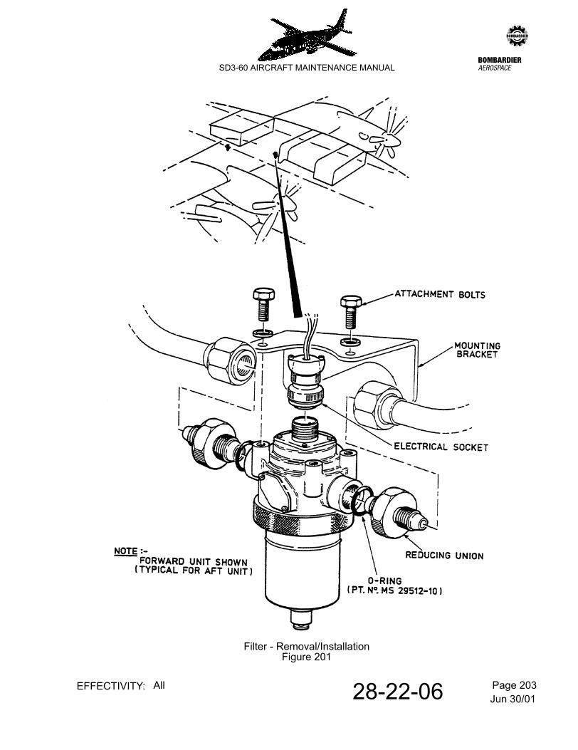
Jun 30/0128-22-06 Page 202EFFECTIVITY: All
zSD3-60 AIRCRAFT MAINTENANCE MANUAL
(4) Unscrew electrical socket.
(5) Disconnect fuel pipes.
NOTE: Observe the direction of flow 'IN' and 'OUT' ports for re-assembly.
(6) Unscrew two attachment bolts and remove the fuel filter.
B. Install a fuel filter
(1) Remove unions and 'O' rings from unserviceable unit. Discard 'O' rings.
(2) Fit unions to replacement unit using new 'O' rings Pt.No.MS29512-10.
(3) Install fuel filter to mounting bracket securing with two bolts and washers observing direction of flow 'IN' and 'OUT' ports as noted during dis-assembly.
(4) Connect the fuel pipes to their appropriate ports and torque tighten and witness mark. Refer to 20-09-04, pb1.
(5) Re-connect electrical socket.
(6) Open fuel isolation valve.
(7) Refer to 12-09-03, pb301. Energise appropriate busbars and provide electrical power to the fuel filter by closing circuit breaker No. 14 on distribution panel 1D (forward fuel filter) or circuit breaker No. 164 on distribution panel 2D (aft fuel filter).
(8) Apply test detailed in para 1.A. (7) and (8).
(9) Replace appropriate access panels on fuselage side and fairing (230BR forward isolation valve and 240PR forward fuel filter or 230ER aft isolation valve and 250CR aft fuel filter). Refer to 6-30-00, pb1.
3. Adjustment/Test
A. Function check filter clogged warning circuit.
Refer to 28-44-00, pb201.
4. Cleaning/Painting
A. Clean filter element
(1) Wash element in clean fuel and blow clear using dry compressed air.
(1) Provide electrical power. Refer to 12-09-03, pb301.
(2) Close circuit breakers No.16 and 320 on left distribution panel 1D and No.166 on right distribution panel 2D.
(3) Select both L.P. shut off valves OPEN.
(4) Check that crossfeed valve is selected SHUT.
(5) Select left engine booster pump ON, noting that the left engine low pressure warning light is extinguished and the right engine low pressure warning light remains illuminated, indicating that the crossfeed valve is SHUT.
(6) Select the crossfeed valve OPEN, noting that the right engine low pressure warning light is now extinguished, indicating the crossfeed valve OPEN.
(7) Select the left engine booster pump OFF.
(8) Select the crossfeed valve and both L.P. shut off valves SHUT.
Jun 30/0128-22-16 Page 201EFFECTIVITY: All
zSD3-60 AIRCRAFT MAINTENANCE MANUAL
AMM28-22-16 17.0.0.0L.P. SHUT OFF VALVE - MAINTENANCE PRACTICES
1. Adjustment/Test
A. Function test the L.P. shut off valve.
(1) Provide electrical power. Refer to 12-09-03, pb301.
(2) Close circuit breakers No.16 and No. 320 on left distribution panel 1D and No. 166 and No. 370 on right distribution panel 2D.
(3) Select the left engine L.P. shut off valve SHUT (detach securing wire which maintains LP lever in OPEN position).
(4) Check that crossfeed valve is selected SHUT.
(5) Select the left engine booster pump ON, noting that the left engine low pressure warning light is illuminated, indicating the L.P. shut off valve SHUT.
(6) Select the left engine L.P. shut off valve OPEN, noting that the left engine low pressure warning light is extinguished, indicating the L.P. shut off valve OPEN.
(7) Select the left engine booster pump OFF.
(8) Re-attach securing wire which maintains LP valve lever in OPEN position.
(9) Repeat paras. (1) to (8) for the right engine L.P. shut off valve.
Jun 30/0128-22-21 Page 201EFFECTIVITY: All
zSD3-60 AIRCRAFT MAINTENANCE MANUAL
AMM28-22-21 18.0.0.0GRAVITY FEED LINE CHECK VALVES - MAINTENANCE PRACTICES
1. Removal/Installation
NOTE: Fuel flow from tank cells 1 and 4 is controlled by twin-poppet check valves (2 off) Part No. 9841022-F and fuel flow from cells 2 and 3 is controlled by single-poppet check valves (3 off) part No. 9841019-F.
Removal and installation of a check valve is straightforward requiring only that the associated tank be drained and that the flow arrow on the unit be properly orientated on installation. However, the following caution must be observed.
CAUTION: TO AVOID LEAK DAMAGE TO THE VALVE BODY WHEN CONNECTING/DISCONNECTING PIPE COUPLINGS, HOLD ONLY THE HEXAGON FLATS ON THE MATING END OF THE VALVE FOR THE ASSOCIATED PIPE. RESTORE LOCKWIRE IF DAMAGED.
2. Cleaning/Painting
A. Clean a check valve.
(1) Dismantle check valve, wash in clean fuel and blow clear using dry compressed air.
(2) Re-assemble check valve and ensure that the poppet/soscillate freely.
Jun 30/0128-22-26 Page 201EFFECTIVITY: All
zSD3-60 AIRCRAFT MAINTENANCE MANUAL
AMM28-22-26 19.0.0.0PRESSURE FEED LINE CHECK VALVES - MAINTENANCE PRACTICES
1. Removal/Installation
NOTE: Fuel flow from forward and aft booster pumps is controlled by single-poppet check valves (2 off) Part No. 9841019-F.
Removal and installation of a check valve is straightforward, requiring only that the associated collector tank be drained and a suitable container positioned for residual fuel on removal, also that the flow arrow on the unit be properly orientated on installation. However, the following caution must be observed.
CAUTION: TO AVOID LEAK DAMAGE TO THE VALVE BODY WHEN CONNECTING/DISCONNECTING PIPE COUPLINGS, HOLD ONLY THE HEXAGON FLATS ON THE \UB\MATING\UE\ END OF THE VALVE FOR THE ASSOCIATED PIPE. RESTORE LOCKWIRE IF DAMAGED.
2. Adjustment/Test
A. Function test the check valve to the right engine.
(1) Remove access panel 240ML above the valves on the fuselage top surface, forward of wing front spar.
(2) Select the aft collector tank isolation valve closed.
(3) Drain the aft collector tank (contents approx. 1 imp. gallon).
(4) Select both L.P. valves SHUT.
(5) Select crossfeed valve OPEN.
(6) Refer to 12-09-03, pb301. Energise the appropriate busbars and provide electrical power to the forward or aft booster pump as applicable by closing circuit breaker No. 320 on distribution panel 1D (forward booster pump) or circuit breaker No. 370 on distribution panel 2D (aft booster pump).
(7) Switch the forward booster pump ON and check for leakage at the aft collector tank drain which should not exceed 5 drops per minute.
(8) Select aft collector tank drain closed.
(9) select aft collector tank isolation valve open.
(10) Repeat paras. (1) to (8) reading forward for aft or aft for forward to test the check valve to the left engine.
A pressure switch tapped into the fuel supply pipe to each engine controls an associated low FUEL pressure warning light (amber) on flight compartment panel 1P. The switch contacts are maintained in the open position under normal supply conditions but, should the pressure fall below 2.0 p.s.i. the contacts changeover to complete the supply to the warning light.
NOTE: On pressure restoration, or on initial selection of a booster pump to ON - the associated warning light should extinguish on a rising fuel delivery pressure not greater than 2.25 p.s.i.
The pressure switches, idented 1WD2 and 2WD2 (left and right respectively) are situated between the inner wings front and rear spars immediately inboard of rib station 106.5.
Jun 30/0128-42-00 Page 1EFFECTIVITY: All
zSD3-60 AIRCRAFT MAINTENANCE MANUAL
AMM28-42-00 22.0.0.0FUEL CONTENTS GAUGING SYSTEM - DESCRIPTION & OPERATION
1. Description
A. General
A capacitance type gauging system is installed to give an accurate indication of the quantity of fuel in the tanks when the aircraft is in a level attitude. The installation consists of two separate systems; one forward and the other aft. The equipment is supplied by Intertechnique.
B. System equipment
(1) Tank probes
Refer to 28-11-00, pb1. The fuel storage tanks comprise four separate cells; cell Nos. 1 & 2 forming the forward tank and cell Nos. 3 and 4 the aft tank. The probe units are allocated to each tank as follows:-
The probe units in cells 1 and 2 are connected in parallel to form the FORWARD group and those in cells 3 and 4 similarly connected to form the AFT group. Each group is fed into an amplifier which supplies quantitive information to a pair of parallel connected indicators.
A probe unit consists of a pair of concentrically mounted glass fibre tubes whose facing surfaces are coated with a silver film to form the electrodes of a capacitor. The level of fuel in the tanks will form the dielectric in each capacitor/probe-thus providing an appropriate electrical input to the amplifier. Each probe unit is mounted on the internal tank structure and interconnections are made with coaxial cables and bayonet-type coaxial plugs and sockets. Connections through the skin of the tanks are by means of bulkhead connectors.
(2) Amplifier
The amplifier for the FORWARD system is mounted on panel 3C and that for the AFT system on panel 4C. Each amplifier unit contains an oscillator, a capacitance measuring bridge, an amplifier and a rectifier. Connections to each unit are via a coaxial bayonet type connector and a multi-pn plug and socket. Each amplifier has two trimmers, one for 'full' and one for 'empty'.
The duplicate pair of indicators supplied by each amplifier are located, one on the pilots' fuel panel 4P and the other on the refuelling panel 8P. The indicators are all of the same type, each consisting of a galvanometer whose pointer has an angular travel of 240° to register the fuel contents.
2. Operation
The operating principle of the system is based on a probe type capacitor whose dielectric consitutes one leg of an impedance bridge, the other leg which is a fixed capacitor supplied from an oppositely phased voltage in order to obtain a null signal when the tank is empty. A change in fuel level will upset the equilibrium of the bridge and the resultant error signal is applied to the input of a closed loop linear amplifier. The characteristics of this amplifier are such as to give an output voltage varying proportionately to the capacitance variation of the probe. Otherwise its negative feed back is very high so that the input voltage is always close to zero.
The a.c. supply for the system is provided from the aircraft 28V d.c. supply by an oscillator built into the amplifier unit. The output from the amplifier is rectified and is then used to drive the galvanometers in the indicators. For each amplifier the variable capacitor consists of six probes connected in parallel and positioned so that the total capacity remains constant regardless of excursions of fuel due to changes of attitude in flight.
3. Power supplies
The power supplies for the installation are normally taken from the 28V dc ESSENTIAL SERVICES busbars via 5 amp circuit breaker Nos.13 on panel 1D for the FORWARD system and No.163 on panel 2D for the AFT). When the ESSENTIAL SERVICES busbars are not energized both systems are supplied from the GROUND SERVICES busbar via a single 5 amp circuit breaker No.254 on panel 2D. The supplies to the two systems are controlled by relays, on panel 1C for the FORWARD system and on panel 2C for the AFT. With the ESSENTIAL SERVICES busbars 'live' and the two circuit breakers closed, each relay is energized to close a pair of contacts and complete the supply to its system. When the ESSENTIAL SERVICES busbars are switched OFF the relays are deenergized to connect the common supply from the 'ground services' busbar to both systems.
Aircraft post mods A8327 and A8464 or post Service Bulletin SD360-24-14, when the ESSENTIAL SERVICES are not energized, supplies are derived from the 26V dc LEFT and RIGHT GROUND ISOLATION busbars via 3 amp C/B Nos 415 and 445 on panels 5D and 6D respectively. With the ESSENTIAL SERVICES busbar live, the two relays on panels 1C and 2C remain de-energized and the amplifiers are powered via the normally-closed contacts of the relays. When an external supply is connected to the aircraft, the two relays are energized and the amplifiers are powered via the normally-open contacts of the relays from the GROUND ISOLATION busbars.
Dec 18/0728-42-00 Page 101EFFECTIVITY: All
zSD3-60 AIRCRAFT MAINTENANCE MANUAL
AMM28-42-00 1.0.0.0FUEL CONTENTS GAUGING SYSTEM - TROUBLESHOOTING
WARNING: THIS MAINTENANCE PROCEDURE IS RELATED TO THE FUEL TANK SAFETY PROGRAMME AND INCORRECT MAINTENANCE COULD ADVERSELY AFFECT THE DESIGN STANDARDS OF THE FUEL TANK SYSTEM. STRICT ADHERENCE TO THE PROCEDURES IN THIS SECTION IS THEREFORE RECOMMENDED.
The Troubleshooting procedure is described in the following pages:-
z
Dec 18/07
28-42-00P
age 102E
FFEC
TIVITY:
All
SD
3-60 AIR
CR
AFT M
AIN
TEN
AN
CE
MA
NU
AL
Fuel Indication Defect
Connect calibration test set as per 28-42-00, pb201.
(CAUTION NOTE 1)NO Change Amplifier and
calibrate as per 28-42-00, pb201 (CAUTION NOTE 1)
Do any Circuit Breakers
trip ?
YES Check insulation resistance of associated feeder
Feeder defective ?
YESChange defective feeder
NO
Is defect on4P and 8P Panel
indicators ?
NO Check which indicator circuit is defective
as per Para.6.
Replace defective indicator and/or replace or repair defective cables as appropriate and calibrate amplifier as per 28-42-00, pb201.
CAUTION - RISK OF EXPLOSIONNOTE 1: DO NOT RESTORE AIRCRAFT WIRING OR RESET CIRCUIT BREAKERS UNTIL AMPLIFIER HAS BEEN ELIMINATED AS THE SOURCE OF THE INDICATION DEFECT AND SUCCESSFULLY CALIBRATED. DO NOT COMPLETE STEPS (9) T0 (12) OF SECTIONS A OR B, IN 28-42-00, PB201.NOTE 2: THIS INSPECTION MUST BE COMPLETED BEFORE THE PHYSICAL TESTS (INSULATION RESISTANCE AND CONTINUITY) ARE CONDUCTED, TO ENSURE THAT ALL POTENTIAL IGNITION SOURCES ARE IDENTIFIED AND ADDRESSED. DAMAGED CABLES AND UNSECURE CONNECTORS IN THE TANK MAY PRESENT AN IGNITION SOURCE.
AmplifierServiceable ?
NO Change amplifier and calibrate per 28-42-00,
pb201. (CAUTION NOTE 1)
YESA
zDec 18/07
28-42-00P
age 103E
FFEC
TIVITY:
All
SD3-60 AIR
CR
AFT MAIN
TENA
NC
E MAN
UAL
A
Connect aircraft harness to amplifier
C
Both indicators
on LOWER stop ?
YESB
E NO
Both indicators on
UPPER stop or excessive
value ?
YESD
NO
Check that fuel indication defect
is fixed
Weatherproof all tank sidewall connectors
as per 28-42-01, pb201 as required
z
Dec 18/07
28-42-00P
age 104E
FFEC
TIVITY:
All
SD
3-60 AIR
CR
AFT M
AIN
TEN
AN
CE
MA
NU
AL
B
CAUTION NOTE 2 Has a
GVI as per Para.1.been successfully
completed ?
Complete general visual inspection (GVI) of harness
installation asper Para.1.
NOC
YES
Has aHI line check
as per Para.2.been successfully
completed ?
Check external high impedance (HI) line
as per Para.2.
NO
YES
Check that fuel indication defect
is fixed
Weatherproof all tank sidewall connectors as per
28-42-01, pb201, as required
zDec 18/07
28-42-00P
age 105E
FFEC
TIVITY:
All
SD3-60 AIR
CR
AFT MAIN
TENA
NC
E MAN
UAL
CAUTION NOTE 2 Has a
GVI as per Para.1.been successfully
completed ?
Complete general visual inspection (GVI) of harness
installation asper Para.1.
DNO
E
YES
Has a LI line check
as per Para.3. been successfully completed
?
Check external low impedance (LI) line
as per Para.3.
NO
YES
Has a LI/HI insulation
resistance check asper Para.4. been
successfully completed
?
Check low impedance (LI) /
high impedance (HI) insulation resistance
as per Para.4.
NO
YES
Has a shield continuity
check as per Para.5.been successfully
completed ?
Check shield continuity as per Para.5.
NO
Weatherproof all tank sidewall connectors as per 28-42-01, pb201,
as requiredCheck fuel indication
defect is fixedYES
Dec 18/0728-42-00 Page 106EFFECTIVITY: All
zSD3-60 AIRCRAFT MAINTENANCE MANUAL
1. Visual Inspection of FCGS Harness Installation
CAUTION: 1: FLAMMABLE FLUID ZONES MUST BE PROPERLY DRAINED AND VENTILATED. USE INDUSTRY STANDARD SAFETY PRACTICES.
2: DO NOT UNDER ANY CIRCUMSTANCES REPAIR ANY FCGS CABLES, ALWAYS REPLACE.
3: BEFORE CLOSING THE TANKS ENSURE THE TANK CLOSE OUT PROCEDURE DETAILED IN CHAPTER 20-09-12, PB201 HAS BEEN SUCCESSFULLY COMPLETED.
A. Outside Fuel Tanks
Refer to CAUTION 1.
(1) Ensure that all connections are secure at amplifier and tank interfaces (28-42-00, pb1, Figure 1).
(2) At each connector ensure that there is no visible damage to the cable or connector (including, for coaxial connectors interfacing with the tank, signs of corrosion or ingress of moisture).
(3) Remove any signs of corrosion or moisture ingress.
(4) If there is visible damage to the connector/cable, replace damaged connector and/or cable.
NOTE: If cables within the cabin need to be replaced, contact:-
(5) Ensure that the weather proofing of the tank wall connectors is intact.
NOTE: If not, follow the procedure for weather proofing of tank sidewall coaxial connectors (refer to 28-42-01, pb201).
B. Inside Fuel Tanks
Refer to CAUTION 1.
Dec 18/0728-42-00 Page 107EFFECTIVITY: All
zSD3-60 AIRCRAFT MAINTENANCE MANUAL
CAUTION: IT IS IMPORTANT TO ENSURE THAT THIS INSPECTION IS COMPLETED BEFORE ELECTRICAL TESTS ARE CONDUCTED, TO IDENTIFY AND ADDRESS ANY POTENTIAL IGNITION SOURCES THAT MAY BE PRESENT DUE TO SYSTEM DEGRADATION / DAMAGE.
(1) Inspect harnesses as detailed in chapter 28-42-03, pb201.
2. High Impedance (HI) Line Check
CAUTION: RISK OF EXPLOSION.
BEFORE THIS TEST IS COMPLETED:-
1: COMPLETE A GENERAL INSPECTION OF THE FCGS HARNESSES WITHIN THE TANK AS DETAILED IN CHAPTER 28-42-03, PB201 AND REPLACE ANY BROKEN OR DAMAGED HARNESSES AND CLIPPING LOCATIONS.ENSURE THAT THE FUEL TANKS ARE PROPERLY DRAINED AND VENTILATED.WHEN COMPLETING INSULATION RESISTANCE CHECK ENSURE THAT 50 VDC RANGE IS SELECTED.DO NOT USE UNAPPROVED EQUIPMENT WITHIN A FLAMMABLE FLUID VAPOUR ZONE.
2: DO NOT UNDER ANY CIRCUMSTANCES REPAIR ANY FCGS CABLES, ALWAYS REPLACE.
A. Disconnect HI coaxial cable from the amplifier
28-42-00, pb1, Figure 101 and 28-42-00, pb1, Figure 1.
B. Insulation resistance test
Equipment Required:-
BMM80 Insulation Resistance Meter or equivalent with capability to test using 50 Vdc.
CAUTION: RISK OF EXPLOSION.PLEASE NOTE THE ABOVE EQUIPMENT IS NOT EXPLOSION PROOF. DO NOT USE INSIDE FUEL TANKS.
(1) Using the above meter, select the 50 Vdc range.
(2) Check the insulation resistance between the HI core (+ve terminal of meter) and the HI screen (-ve terminal of meter) of the HI coaxial cable.
(3) If insulation resistance is less than 50 kOhms:-
(a) Disconnect all connectors at the tank sidewalls.
Dec 18/0728-42-00 Page 108EFFECTIVITY: All
zSD3-60 AIRCRAFT MAINTENANCE MANUAL
(b) Repeat check for external HI lines (including T-unions) only and replace if defective.
NOTE: If cables within the cabin need to be replaced, contact:-
1: COMPLETE A GENERAL INSPECTION OF THE FCGS HARNESSES WITHIN THE TANK AS DETAILED IN CHAPTER 28-42-03, PB201 AND REPLACE ANY BROKEN OR DAMAGED HARNESSES AND CLIPPING LOCATIONS.ENSURE THAT THE FUEL TANKS ARE PROPERLY DRAINED AND VENTILATED.WHEN COMPLETING INSULATION RESISTANCE CHECK ENSURE THAT 50 VDC RANGE IS SELECTED.DO NOT USE UNAPPROVED EQUIPMENT WITHIN A FLAMMABLE FLUID VAPOUR ZONE.
2: DO NOT UNDER ANY CIRCUMSTANCES REPAIR ANY FCGS CABLES, ALWAYS REPLACE.
A. Disconnect circular connector (LI coaxial cable) from the amplifier
28-42-00, pb1, Figure 101 and 28-42-00, pb1, Figure 1.
B. Insulation resistance test
Equipment Required:
BMM80 Insulation Resistance Meter or equivalent with the capability to test using 50 Vdc.
CAUTION: RISK OF EXPLOSION.PLEASE NOTE THE ABOVE EQUIPMENT IS NOT EXPLOSION PROOF. DO NOT USE INSIDE FUEL TANKS.
(1) Using the above meter, select the 50 Vdc range.
(2) Check the insulation resistance between the LI core, pin ‘C’ (+ve terminal of meter) and the LI screen, pin ‘D’ (-ve terminal of meter) of the FCGS harness connector.
(3) If insulation resistance is less than 50 kOhms:-
(a) Repeat check for external LI lines (including T-unions) only and replace if defective
NOTE: If cables within the cabin need to be replaced, contact:-
4. Low to High Impedance (LI/HI) Insulation Resistance Check
CAUTION: RISK OF EXPLOSION.
BEFORE THIS TEST IS COMPLETED:-
CAUTION: 1: COMPLETE A GENERAL INSPECTION OF THE FCGS HARNESSES WITHIN THE TANK AS DETAILED IN CHAPTER 28-42-03, PB201 AND REPLACE ANY BROKEN OR DAMAGED HARNESSES AND CLIPPING LOCATIONS.ENSURE THAT THE FUEL TANKS ARE PROPERLY DRAINED AND VENTILATED.WHEN COMPLETING INSULATION RESISTANCE CHECK ENSURE THAT 50VDC RANGE IS SELECTED.DO NOT USE UNAPPROVED EQUIPMENT WITHIN A FLAMMABLE FLUID VAPOUR ZONE.
2: DO NOT UNDER ANY CIRCUMSTANCES REPAIR ANY FCGS CABLES, ALWAYS REPLACE.
A. Disconnect HI coaxial cable and circular connector (LI coaxial cable) from the amplifier.
28-42-00, pb1, Figure 101 and 28-42-00, pb1, Figure 1.
B. Insulation resistance test
Equipment Required:
BMM80 Insulation Resistance Meter or equivalent with the capability to test using 50 Vdc.
CAUTION: RISK OF EXPLOSION.PLEASE NOTE THE ABOVE EQUIPMENT IS NOT EXPLOSION PROOF. DO NOT USE INSIDE FUEL TANKS.
(1) Using the above meter, select the 50 Vdc range.
(2) Check the insulation resistance between the HI coaxial cable core (+ve terminal of meter) and the LI coaxial cable core, circular connector pin ‘C’ (-ve terminal of meter).
Dec 18/0728-42-00 Page 111EFFECTIVITY: All
zSD3-60 AIRCRAFT MAINTENANCE MANUAL
(3) If insulation resistance is less than 1 MOhm:-
(a) Disconnect all tank sidewall connectors.
(b) Repeat check between HI core (P2) and LI core (P1) at each tank sidewall bulkhead connector plate in turn (QB5, QB6, QB7 AND QB8).
(c) If insulation resistance is still less than 1 MOhm on a Fuel Tank Cell, contact:-
(4) Reconnect all connectors after successful test.
5. Coaxial Shield Continuity Check
CAUTION: RISK OF EXPLOSION.
1: CONTINUITY TESTER – BATTERY POWERED, 5V DC OR LESS.ELECTRICAL BONDING METER – BT51 OR EQUIVALENT.
CAUTION: FOR ELECTRICAL BONDING TESTS IN A FLAMMABLE FLUID VAPOUR ZONE USE AN EXPLOSION PROOF METER, SUCH AS BCD M-1 BONDING METER.
2: DO NOT UNDER ANY CIRCUMSTANCES REPAIR ANY FCGS CABLES, ALWAYS REPLACE.
3: ENSURE TANK IS PROPERLY DRAINED AND VENTILATED.
A. Amplifier Electrical Bonding Check
(1) Disconnect HI line and circular connector (LI line) from the amplifier (28-42-00, pb1, Figure 101 and 28-42-00, pb1, Figure 1.
(2) Measure the electrical bonding resistance between the amplifier co-axial receptacle and aircraft primary structure as detailed in chapter 20-09-05, pb201.
NOTE: If electrical bonding resistance to structure is greater than the maximum value stated then re-establish electrical bond.
(3) Reconnect system connectors.
B. Shield Continuity Check
(1) Disconnect HI line from the amplifier (28-42-00, pb1, Figure 1).
Dec 18/0728-42-00 Page 112EFFECTIVITY: All
zSD3-60 AIRCRAFT MAINTENANCE MANUAL
(2) Complete continuity check between the coaxial cable connector shell and primary structure.
(3) If continuity is not established, disconnect in turn each coaxial FCGS cable external to the tank from the system and:-
(a) Check separately for continuity between connectors (for the co-axial FCGS cable connected to the circular connector of the amplifier, check between the co-axial connector and the amplifier circular connector pin ‘D’).
(b) If continuity has not been established, restore continuity of cable shield by remaking the connection between the cable and the associated connectors.
NOTE: Only one remake is allowed per end.
(c) If the cable is damaged or remaking each end cannot restore continuity, then replace the cable (Refer to CAUTION 2).
(d) If the coaxial cable between the amplifier and the tank sidewall has to be replaced, contact:-
(5) Disconnect the LI line, between the amplifier and the probes, at the tank wall interface.
(6) Disconnect the HI line at the amplifier.
(7) Complete continuity check between the LI line coaxial cable connector shell at the tank sidewall interface and primary structure.
(8) If continuity is not established, disconnect the associated FCGS amplifier circular connector and:-
(a) Check the continuity between the amplifier circular connector pin ‘D’ and pin ‘E’ on the amplifier.
NOTE: If there is no continuity replace the amplifier.
(b) Check the continuity between pin ‘E’ of the amplifier harness connector and the aircraft structure. Restore continuity by re-establishing ground connection.
(9) Reconnect all co-axial harnesses.
Dec 18/0728-42-00 Page 113EFFECTIVITY: All
zSD3-60 AIRCRAFT MAINTENANCE MANUAL
(10) If all external shields have continuity without rework and there is still a fuel indication defect, proceed as follows:-
(a) At each tank sidewall connector, disconnect both LI and HI lines and complete a continuity check between the bulkhead connectors.
(b) If continuity is not established, then troubleshoot to identify shield discontinuity and re-establish by remaking the connection between the cable and the associated connectors.
NOTE: Only one remake is allowed per end.
(c) If the cable is damaged or remaking each end cannot restore continuity, then replace the cable (Refer to CAUTION 2).
6. Defective Indicator Circuit Check
A. General
(1) Disconnect the circular connector from each amplifier.
(2) Change the indicator which is not on the zero position.
(3) Re-connect all circular connectors that were disconnected from the amplifiers.
Jun 30/0128-42-00 Page 201EFFECTIVITY: All
zSD3-60 AIRCRAFT MAINTENANCE MANUAL
AMM28-42-00 24.0.0.0FUEL CONTENTS GAUGING SYSTEM - MAINTENANCE PRACTICES
1. Calibrate the System
Special Tools & Equipment:-
NOTE: The referenced Test Set provides switched capacitances relative to gauge zero and full scale deflection indications i.e. 0 and 2200 1bs (1000 kg). To enable operators holding suitable variable capacitance test sets to calibrate the system, the capacitance values relative to empty and operational full fuel loads are referenced throughout the procedural text.
A. Calibrate forward Tank Gauges
(1) Open C/B Nos. 13 on panel 1D and 163 and 254 on panel 2D.
NOTE: On Aircraft post mods A8327 and A8464 or post Service Bulletin SD360-24-14, also trip C/B Nos 415 on panel 5D and 445 on panel 6D.
(2) Remove local furnishing below Left Distribution panel 1D to locate amplifier idented QB47 on equipment panel 3C.
(3) Refer to Figure 201. Connect Test Set as follows:-
(a) Disconnect multi-core plug from amplifier and reconnect with test set 4 in. fly-lead introduced between plug and amplifier socket.
(b) Connect the free end of the co-ax cable which is integral with the 4 in. flylead to the P1 connection on the test set.
(c) Disconnect system co-ax cable from amplifier and replace with test co-ax, the test end of which is to be attached to P2.
(d) Connect test sets ground lead to E81 on left side of frame 54.
(4) Connect a Digital Voltmeter (D.V.M.) to terminals of FWD TANK fuel gauge on panel 4P.
(5) Refer to 12-09-03, pb301. Connect an external electrical power unit to the aircraft and close all circuit breakers tripped in para (1).
(6) Set test set switch (amplifier 706-403) to EMPTY.
NOTE: This will provide a test set selected capacitance for gauge zero indication of 189 ± 2 picofarads.
(7) Adjust empty trimmer (E) on amplifier such that D.V.M indicates 0V +0 -15 mV and FWD
Calibration Test Set T360.28.04Digital Voltmeter
Jun 30/0128-42-00 Page 202EFFECTIVITY: All
zSD3-60 AIRCRAFT MAINTENANCE MANUAL
TANK gauge on panel 4P registers zero. Check that the corresponding gauge on the refuelling panel 8P reads less than 20 lb (9 kg).
(8) Perform (a) or (b) as appropriate to test set employed:-
(a) Specified Test Set:-
Set test set switch to FULL and adjust full trimmer (F) on amplifier such that FWD TANK gauge on panel 4P registers full scale deflection i.e. 2200 1b. (1000 kg). Check that associated gauge on refuelling panel 8P concurs within 20 1b. (9 kg).
(b) Variable Capacitance Test Set:
Set up a capacitance of 353 ± 4 picofarads and adjust the amplifiers full trimmer (F) such that the DVM indicates 4.25V +0 -20 mV and the FWD
TANK gauge on panel 4P registers 1884 1b (856 kg). Check that corresponding gauge on the refuelling panel 8P concurs within 20 1b (9 kg).
NOTE: To check the amplifier throughout the range, simulated step-checking of various intermediate fuel levels may be performed using the advisory information detailed in para C.(1).
(9) Open circuit breakers listed in para (1), remove test set and restore aircraft wiring.
(10) Establish existing tank contents by summating the dipstick readings for Cells 1 and 2 in Imp. Gal. and based on a mean fuel specific gravity of 0.795, convert to 1b or kg as appropriate to gauge registrations as follows:-
Contents in 1b = Imp. Gal x 7.95
Contents in kg = Imp. Gal x 3.61
(11) Close circuit breakers tripped in para (1) and check that the FWD TANK gauge on panel 4P reads witin 50 1b (23 kg) of figure obtained in para. (10).
(12) Open circuit breakers listed in para. (1) and refit furnishing.
B. Calibrate Aft Tank Gauges
(1) Open C/B Nos.13 on panel 1D and 163 and 254 on panel 2D.
NOTE: On Aircraft post mods A8327 and A8464 or post Service Bulletin SD360-24-14, also trip C/B Nos 415 on panel 5D and 445 on panel 6D.
(2) Remove local furnishing below Right Distribution Panel 2D to locate amplifier idented QB47 on equipment panel 4C.
Jun 30/0128-42-00 Page 203EFFECTIVITY: All
zSD3-60 AIRCRAFT MAINTENANCE MANUAL
(3) Refer to Figure 201. Connect Test Set as follows:
(a) Disconnect multi-core plug from amplifier and reconnect with test set 4 in. flylead introduced between plug and amplifier socket.
(b) Connect the free end of the co-ax cable which is integral with the 4 in. flylead to the P3 connection on the test set.
(c) Disconnect system co-ax cable from amplifier and replace with test co-ax, the test set end of which is to be attached to P4.
(d) Connect test sets ground lead to E82 on right of frame 54.
(4) Connect a Digital voltmeter to the terminals of AFT TANK fuel gauge on panel 4P.
(5) Refer to 12-09-03, pb301. Connect an external electrical power unit to the aircraft and close those circuit breakers tripped in para (1).
(6) Set test switch (amplifier 706-404) to EMPTY.
NOTE: This will provide a test set selected capacitance for gauge zero indication of 182 ± 2 picofarads.
(7) Adjust empty trimmer (E) on amplifier such that DVM indicates 0V +0 -15 mV and AFT TANK gauge on panel 4P registers zero. Check that the corresponding gauge on the refuelling panel 8P reads less than 20 lb (9 kg).
(8) Perform (a) or (b) as appropriate to test set employed:-
(a) Specified Test Set:-
Set test switch to FULL and adjust full trimmer (F) on amplifier such that AFT TANK gauge on panel 4P registers full scale deflection i.e. 2200 lb (1000 kg). Check that associated gauge on refuelling panel 8P concurs within 20 lb (9 kg).
(b) Variable Capacitance Test Set:-
Set up a capacitance 345 ± 4 picofarads and adjust the amplifiers full trimmer (F) such that the DVM indicates 4.25V +0 -20 mV and the AFT TANK gauge on panel 4P registers 1884 lb (856 kg). Check that refuelling panel indication concurs within 20 lb (9 kg).
NOTE: To check the amplifier throughout the range, simulated step-checking of various intermediate fuel levels may be performed employing the advisory information detailed in para C (1).
Jun 30/0128-42-00 Page 204EFFECTIVITY: All
zSD3-60 AIRCRAFT MAINTENANCE MANUAL
Test ArrangementFigure 201
Jun 30/0128-42-00 Page 205EFFECTIVITY: All
zSD3-60 AIRCRAFT MAINTENANCE MANUAL
(9) Open circuit breakers listed in para. (1), remove test set and restore aircraft wiring.
(10) Establish existing tank contents by summating the dipstick readings for Cells 3 and 4 in Imp. Gal. and based on a mean fuel specific gravity of 0.795, convert to 1b or kg as appropriate to gauge registrations as follows:-
Contents in lb = Imp. Gal. x 7.95
Contents in kg = Imp. Gal. x 3.61
(11) Close circuit breakers tripped in para. (1) and check that the AFT TANK gauge on panel 4P reads within 50 1b (23 kg) of the figure obtained in para (10).
(12) Open circuit breakers listed in para (1) and refit furnishing.
C. Advisory Information
(1) Range checking of system amplifiers:
NOTE: The subject function is only applicable to those operators employing variable capacitance test sets. The following information will facilitate the check.
Explanation of formulae employed to establish the required theoretical input capacitance relative to an expected gauge reading for an intermediate fuel loading follow:-
NOTE: Between the empty and operational full capacitance there is a constant ratio of 11.52 1b (5.23 kg) per picofarad (forward tank group) and 11.59 1b (5.26 kg) per picofarad (aft tank group); this gives a linear displacement of the gauge pointers for a given tank content.
The theoretical cpacitance value CpF for a particular fuel quantity Q in 1b or Kg can be established thus:-
Forward tank:
Aft tank:
(a) CpF = 189 + 0.0868Q ± 6pF) gauge reading lb.
(b) CpF = 189 + 0.1914Q ± 6Pf gauge reading kg
(a) CpF = 182 + 0.0863Q ± 6pF gauge reading lb.
(b) CpF = 182 + 0.1903Q ± 6pF gauge reading kg
Jun 30/0128-42-00 Page 206EFFECTIVITY: All
zSD3-60 AIRCRAFT MAINTENANCE MANUAL
NOTE: At the following indicated fuel quantities the DVM voltages applicable at the indicator terminals are:-
(2) Tank probe group capacitance checks:
When determined by a suitable meter, the capacitance values relative to known fuel loadings should be confirmed within tolerance when checked against the expected values derived from the appropriate formula presented in para (1).
AMM28-42-01 25.0.0.0FUEL CONTENTS CO-AXIAL CONNECTORS ON TANK SIDEWALLS MAINTENANCE PRACTICES
1. General
Moisture ingress to the fuel contents co-axial connectors on the fuel tank sidewalls can result in erratic contents indication. Service Bulletin SD360-28-06 (related Mod No A7643) introduces weather-proofing of the connectors using a silicone based compound to the specification and availability detailed in para 2.
The location of the relevant connectors is given in para 3.
NOTE: IMPORTANT: If a connector is disturbed as a result of maintenance activity or the weather-proofing is observed to have broken down during a zonal inspection, it is essential that the weather-proofing be restored as advised in para 4.
2. Silicone Compound, Specification and suppliers
3. Connector Locations
A. Forward Tank Group:
NOTE: This includes Cell No.3 which is operationally part of the aft tank.
(1) With the relevant connector(s) as listed in para 3 disconnected, inspect and if necessary clean off any moisture and/or corrosion which may be present.
(2) After final re-connection of connector(s), apply a film of silicone compound MS4 or DC4 (para 2) to external surfaces.
(3) When silicone compound is 'tack-free', refit access panels.
2QB32QB4
))
Tee ))
Cell No 3,right side
))
240ER & 240GR,right side
CircuitIdent
ConnectorType Position Access Panels
Refer to 6-30-00, pb1.)
QB8 P1QB8 P2
))
Straight right Aft roof fairing:250CR & 250FR,right side
CircuitIdent
ConnectorType Position Access Panels
(Refer to 6-30-00, pb1.)
Dec 18/0728-42-02 Page 201EFFECTIVITY: All
zSD3-60 AIRCRAFT MAINTENANCE MANUAL
AMM28-42-02 1.0.0.0FUEL CONTENTS GAUGING SYSTEM (FCGS) CABLES EXTERNAL-TO-TANKMAINTENANCE PRACTICES
WARNING: THIS MAINTENANCE PROCEDURE IS A FUEL TANK SAFETY CRITICAL ITEM, AND CLASSIFIED AS BOTH AN AIRWORTHINESS LIMITATION ITEM (ALI) AND A CRITICAL DESIGN CONFIGURATION CONTROL LIMITATION BY THE AIRCRAFT OEM ( FUEL SYSTEM AIRWORTHINESS LIMITATION ITEMS - CHECKS, PB601 AND 5-20-02, PB1).THE CONTENTS OF THIS PROCEDURE MUST BE STRICTLY ADHERED TO AND MUST NOT BE ALTERED TO ENSURE THAT UNSAFE CONDITIONS DO NOT DEVELOP BY MAINTENANCE, MODIFICATION OR REPAIR.
1. General
The FCGS cables are routed in segregation A and B harness. refer to Figure 201 (Sheet 1) for the exact routing within the cabin and fairing areas.
2. Safety Precautions
A. Procedure
(1) Obey the safety precautions as follows:-
(a) The routing of additional electrical power/signal cables is not permitted within six inches of the FCGS cables.
(b) If a wire bundle that has FCGS cables within has to be divided, take care not to apply force on any of the cables.
3. Inspection of Harness Routing
The harness routing identified should be inspected as follows:-
NOTE: Do not cut tie-wrap etc. and penetrate the harness to complete the inspection. A detailed visual inspection of the condition of the visible portions of the external cables is sufficient.
(1) Make sure that all clipping positions are secure and undamaged.
(2) Inspect the harness at damaged, loose or missing clipping positions and between the first undamaged clipping position, either side of the former, for damage to the insulation (cracks, fretting etc.).
(3) Inspect the harness in way of the FCGS connectors, to ensure they are secure and that the cable local to the connector is not damaged.
(4) Replace any damaged, loose or missing clips, to re-establish clipping positions.
(5) Inspect the harness run at all bend radii and lightening hole locations, for damage to insulation (refer to Figure 201 (Sheet 1)).
Dec 18/0728-42-02 Page 202EFFECTIVITY: All
zSD3-60 AIRCRAFT MAINTENANCE MANUAL
(6) Inspect the harness run for signs of contamination (eg. swarf). Where contamination is suspected, remove the material using a vacuum cleaner and/or soft brush and perform a visual check.
4. Damage Detection
WARNING: DAMAGED FCGS CO-AXIAL CABLES ARE A POTENTIAL FUEL TANK IGNITION SOURCE AND MUST BE REPLACED, NOT REPAIRED.
If damage is detected, report the condition and for further instruction, contact:-
AMM28-42-03 1.0.0.0FUEL CONTENTS GAUGING SYSTEM (FCGS) CABLES INTERNAL-TO-TANKMAINTENANCE PRACTICES
1. General
WARNING: THIS MAINTENANCE PROCEDURE IS A FUEL TANK SAFETY CRITICAL ITEM, AND CLASSIFIED AS BOTH AN AIRWORTHINESS LIMITATION ITEM (ALI) AND A CRITICAL DESIGN CONFIGURATION CONTROL LIMITATION (CDCCL) BY THE AIRCRAFT OEM (CHAPTER FUEL SYSTEM AIRWORTHINESS LIMITATION ITEMS - CHECKS, PB601 AND CHAPTER 5-20-02, PB1).THE CONTENTS OF THIS PROCEDURE MUST BE STRICTLY ADHERED TO AND MUST NOT BE ALTERED TO ENSURE THAT UNSAFE CONDITIONS DO NOT DEVELOP BY MAINTENANCE, MODIFICATION OR REPAIR.
The inspection that follows is applicable to cables of the fuel contents gauging system inside each of the fuel tanks.
2. Safety Precautions
WARNING: ENSURE THAT THE FOLLOWING FIRE PRECAUTIONS ARE OBSERVED WHEN WORKING ON THE FUEL TANKS:-
CHECK THAT ALL ELECTRICAL SUPPLIES IN THE AIRCRAFT ARE OFF. REMOVE THE BATTERIES AND ENSURE THAT GROUND SUPPLY IS NOT CONNECTED TO THE AIRCRAFT.
ENSURE THAT ALL HANDLAMPS OR TORCHES USED TO ILLUMINATE THE INTERIOR OF THE TANKS ARE OF AN APPROVED ‘EXPLOSION PROOF’ DESIGN SUITABLE FOR USE IN ENVIRONMENTS CLASSIFIED BY THE US NATIONAL ELECTRICAL CODE AS DIVISION 1, CLASS 1, GROUPS A, B, C, & D, AND ARE IN GOOD CONDITION.
CONNECT AN EARTH (GROUND) WIRE TO THE AIRCRAFT STRUCTURE, ANY PLATFORMS, AND CASINGS OF ELECTRICALLY POWERED EQUIPMENT USED DURING THIS TASK.
ENSURE THAT SUITABLE FIRE FIGHTING EQUIPMENT IS AVAILABLE AND IS CAPABLE OF REACHING ANY PART OF THE AIRFRAME.
A. Isolate power supplies
(1) Remove the main batteries (refer to 24-33-01, pb201).
(2) Remove the tail emergency battery (refer to 24-33-06, pb201).
(3) Ensure external ground supply is disconnected:-
(a) Close the ground supply connector flap door and secure in closed position with masking tape.
Dec 18/0728-42-03 Page 202EFFECTIVITY: All
zSD3-60 AIRCRAFT MAINTENANCE MANUAL
(4) Prominently tag the battery and ground supply locations with a CAUTION, as detailed in chapter 12-09-03, pb1.
3. Visual Inspection
WARNING: DAMAGED FCGS CO-AXIAL CABLES ARE A POTENTIAL FUEL TANK IGNITION SOURCE AND CABLE ASSEMBLIES MUST BE REPLACED, NOT REPAIRED.
A. Procedure
(1) Ensure that all clipping positions are present, secure and undamaged.
(2) Inspect the cables in way of loose, damaged or missing clips for signs of damage. Replace any damaged cable assemblies.
(3) Inspect the cables in way of the FCGS connectors, to ensure they are secure and that the cable local to the connector is not damaged. Replace any damaged cable assemblies.
(4) Ensure that cables routed inside the tank do not rub against the adjacent structure. Particular attention should be given to cables routed through lightening holes. Inspect cables where signs of rubbing are evident. Replace any damaged cable assemblies.
(5) Replace any loose, damaged or missing clips and re-establish clipping positions.
Four dipsticks are installed, one in each fuel cell. Basically this equipment consists of a blade, calibrated in IMP and US GALLS, which is fixed at the upper end to a spring-loaded bayonet type fitting. Each assembly inserts into and connects to a tank attached housing.
A dipstick is released from the stowed position by depressing the head inwards with a screwdriver and turning it through 90°, it will then be ejected free of the housing by spring pressure.
To refit, the head is depressed and turned until the screwdriver slot is in line with the legends LOCK engraved on the housing.
Indication of impending bypassing of the element within the filter units in the fuel delivery line from each booster pump is provided by FILTER clogged warning lights (amber) on the fuel services section of flight compartment roof panel 4P.
The left and right filter units, idented 1WN2 and 2WN2 respectively, each incorporate an internal switch, the contacts of which when made, complete an electrical supply to the appropriate warning light.
Power supplies are taken from the left and right 28V d.c. essential services busbars via 5 amp circuit breakers respectively positioned on distribution panels 1D and 2D.
2. Operation
When as a result of element clogging, the Delta P across the unit rises to 3.5 ± 0.5 p.s.i.d. the switch contacts changeover to complete the supply to the warning light. Initial illumination of the light warns of impending bypass action.
NOTE: The filter units internal bypass opens at 4.5 p.s.i.d. minimum.
The circuit, switch and bypass valve are operationally checked as follows:-
(1) Gain access to the filter units by opening panels 240RR and 240DR on the right hand side of the fuselage roof fairing.
(2) Isolate booster pumps (trip C/B No.320 and 370 on distribution panels 1D and 2D respectively).
(3) Refer to 12-09-03, pb301. Provide electrical power.
(4) Close C/B No.14 and 164 on panels 1D and 2D respectively.
(5) Refer to Figure 201. At each filter unit in turn, perform the following:-
(a) Remove filter can and element.
(b) Introduce a suitable blunt probe into the housing inlet chamber, apply at point A and move the switch operating vane to depress the impending bypass plunger, checking that the appropriate FILTER clogged warning light on panel 4P illuminates.
(c) Release switch operating vane and check that light is extinguished proving that the switch operating plunger within the bypass valve assembly freely returns under its spring load.
(d) Apply probe at point B and move the whole bypass valve assembly against the external helical spring to lift the valve off its seat and check:-
1 The appropriate warning light is on i.e. the microswitch operating mechanism has followed the valve assembly without the use of the probe as detailed at (b).
2 When the probe is removed, the valve freely reseats under spring load (warning light is extinguished).
(e) Clean filter element and refit element and filter can. Refer to 28-22-06, pb201.
Indication for each fuel levelling valve OPEN/CLOSED state is afforded by indicator modules situated on the FUEL SERVICES panel 4P.
2. Operation
With electrical power available and the FUEL LEVELLING switch selected to either OPEN or CLOSED the indicator module will provide the appropriate OPEN/CLOSED indication.
3. Power Supplies
Power is supplied from the 28V Right Ground Services Busbar through a 5 amp breaker on distribution panel 2D.
Indication and warning that a crossfeed valve open selection has been made is provided by:-
A. the illumination of the horizontal bar of the crossfeed magnetic indicator on FUEL panel 4P
B. the illumination of the FUEL X warning caption on panel 1P.
The circuit is activated through a microswitch idented WU1 which is operated by the valve control lever.
2. Operation
With electrical power available, selection of the CROSSFEED VALVE control lever to the OPEN (forward) position will actuate the microswitch and complete the circuit to the indication and warning lights.
3. Power Supplies
Power is supplied from the 28 V dc Right Essential Services Busbar via circuit breaker No. 197 (5 amp) on distribution panel 2D.
Jun 30/0128-46-00 Page 201EFFECTIVITY: All
zSD3-60 AIRCRAFT MAINTENANCE MANUAL
AMM28-46-00 32.0.0.0CROSSFEED VALVE 'OPEN INDICATION' AND WARNING - MAINTENANCE PRACTICES
1. Adjustment/Test
A. Function check
(1) Refer to 12-09-03, pb301. Energise the 28 V dc Right Essential Services Busbar and close circuit breaker No. 197 on distribution panel 2D.
(2) Select fuel CROSSFEED VALVE control lever on flight compartment roof console to OPEN (forward) position and check for illumination of
(a) the horizontal bar of the crossfeed magnetic indicator on FUEL panel 4P
(b) the FUEL X warning caption on panel 1P.
(3) Re-select fuel CROSSFEED VALVE SHUT and check that the vertical bar of the crossfeed magnetic indicator is illuminated and the FUEL X caption extinguished.
B. Adjust the microswitch
(1) Gain access to the microswitch idented WU1 (roof console) by removing forward section of the bottom cover.
(2) Refer to 12-09-03, pb301. Provide electrical power and close circuit breaker No. 197 on distribution panel 2D.
(3) Rig the microswitch
(a) Slacken the bottom nut of the microswitch mounting bracket and pivot the assembly forward.
(b) Select the fuel CROSSFEED VALVE control lever in the roof console to the OPEN (forward) position.
(c) Slowly pivot the microswitch assembly aftwards until the switch operates, causing the horizontal bar on the crossfeed magnetic indication (panel 4P) and the FUEL X caption (panel 1P) to illuminate.
(d) Tighten the nut on the microswitch mounting plate.
(e) Check that CROSSFEED VALVE control lever and microswitch roller are centrally aligned.
(f) Check the vertical bar on the crossfeed magnetic indicator is illuminated and the FUEL X caption extinguished as the lever is moved from the OPEN gated position.
(4) Return the fuel CROSSFEED VALVE control lever to the SHUT position.
(5) Replace forward section of roof console bottom cover assembly.
The fuel low level warning system illuminates electrical indicators in the flight compartment, warning of low fuel level in the forward or rear tank.
The main components of the warning system are:
Two independent low liquid level sensors, one in the forward and one in the rear fuel tanks; two electrical indicators in the flight compartment central warning system.
2. Component Description
A. Low level sensors
The low level sensor detects fuel levels of 330 lb and below in the forward fuel tank and 295 lb and below in the rear fuel tank (± 75lb). A time delay circuit reduces spurious signals: on sensor immersion up to 15 seconds delay before warning is cancelled; when clear of fuel up to 5 seconds delay before warning is initiated.
The sensors are located on the fuel tanks LH sidewall (36.0V); forward tank at Stn.192.2, 98.10H and the rear tank at Stn.348.0, 94.95H. The sensors project horizontally into the fuel tank and are secured through a mating threaded flange. Electrical connection is through an externally connected plug.
B. Electrical indicators
The indicators illuminate when a low fuel level is present in either the forward tank and/or the rear tank (Refer para 2.A.).
The indicators are located on the flight compartment central warning system display. The captions are black letters on an amber background, LOW FUEL FWD and LOW FUEL AFT.
3. Operation
A. The sensor probe incorporates a light source and a photo-cell coupled by a fibre-optic link. With the probe tip immersed in fuel the light path is interrupted and a photo-cell controlled switch circuit inhibits electrical signals to the warning indicator. As the tip is uncovered the photo-cell senses the light source and the photo-cell controlled switch circuit connects power to the appropriate electrical indicator warning.
4. Power supplies
A. Electrical power to the system is provided from the 28V d.c. LH ESS BUS. protected by circuit breaker 81, distribution panel 1D and, 28V d.c. RH ESS BUS. protected by circuit breaker 232, distribution panel 2D.
WARNING: ENSURE THAT THE FOLLOWING PRECAUTIONS ARE OBSERVED WHEN WORKING ON THE FUEL TANKS.
1. CHECK THAT ALL ELECTRICAL SUPPLIES IN THE AIRCRAFT ARE OFF. REMOVE THE BATTERIES AND ENSURE THAT THE GROUND SUPPLY IS NOT CONNECTED TO THE AIRCRAFT.
2. ENSURE THAT ALL HAND LAMPS OR TORCHES USED TO ILLUMINATE THE INTERIOR OF THE TANKS ARE OF AN APPROVED FIREPROOF DESIGN AND IN GOOD CONDITION.
3. CONNECT AN EARTH (GROUND) CABLE TO THE AIRCRAFT STRUCTURE.
4. ENSURE THAT SUITABLE FIRE FIGHTING EQUIPMENT IS AVAILABLE AND IS CAPABLE OF REACHING ANY PART OF THE AIRFRAME.
NOTE: Ensure appropriate placards are in place. Refer to 12-09-03, pb301.).
1. Removal/Installation
NOTE: Two identical low level sensors are installed, forward tank and aft tank. Only the Removal/Installation of the forward tank sensor is shown, differences are given in parenthesis.
A. Remove low level fuel sensor, EM2098-1.
(1) Drain all fuel from forward (rear) fuel tank.
(2) Refer to 6-30-00, pb1. Remove the following roof access panels : 240HL and 240KL (250CL and 250FL).
(3) Locate low level sensor, on fuel tank LH sidewall, Stn 192.2, 98.10H (Stn 348.0, 94.95H).
(4) Disconnect electrical connection to the sensor. To prevent damage or ingress of foreign objects protect both ends of electrical connection using approved blanks.
(5) Unscrew the sensor from its mounting flange and withdraw the sensor and O-ring seal from the tank. To prevent damage or ingress of foreign objects to tank, install approved blank.
B. Install low level fuel sensor, EM2098-1.
(1) Gain access to forward (rear) fuel tank LH sidewall. Remove blank from mounting flange, install sensor with O-ring seal (MS29512-8) and tighten.
(2) Remove blanks from both electrical connections and attach connector to sensor ensuring correct alignment of the pins.
Jun 30/0128-47-00 Page 202EFFECTIVITY: All
zSD3-60 AIRCRAFT MAINTENANCE MANUAL
(3) Install roof access panels 240HL and 240KL (250CL and 250FL) using attaching fasteners retained from removal.
(4) Remove signs, placards etc. and perform system function check, para 2.
2. Adjustment/Test
NOTE: Two levels of function test may be performed on the low fuel level warning system, test A and test B. Test A checks the servicability of the electrical indicator filaments and the integrity of the low fuel level warning system complete. Test B is performed when one or both low level sensors have been replaced.
A. Test A. Function test the low level warning system.
(1) Refer to 12-09-03, pb301. Provide electrical power to the aircraft.
(2) Refer to 31-50-00, pb201. Check that all 1P warning/indicator annunciators and other flight compartment warning/indicator light are not illuminated. Trip any associated system circuit breakers necessary to achieve this.
(3) Select TEST on the TEST/BRT/DIM switch on panel 11P.
NOTE: This action operates a test lamp in each low level sensor. In turn this operates the photo-cell in the sensor which initiates the warning via a delay circuit only if current is flowing to the main lamp in the sensor. Thus a test of the system can be performed at any time the fuel level is above the probe tip.
(4) Check that the LOW FUEL FWD and LOW FUEL AFT electrical indicators are illuminated after a delay of 1 to 5 seconds.
(5) Release the TEST switch and check that the LOW FUEL FWD and LOW FUEL AFT electrical indicator lights extinguish after a delay of 5 to 15 seconds.
(6) Re-set any circuit breakers opened in Para (2) and return the aircraft to the unpowered state.
B. Test B. Function test the low level sensor.
(1) Raise the aircraft on jacks to an attitude of + 2 degrees pitch and zero degrees roll. Refer to 7-10-00, pb201.
(2) Check that both aircraft fuel systems have been drained, and the following valves are at the positions indicated:
(a) Crossfeed valves - SHUT(b) L.P. valves - SHUT(c) Collector tank drain valves - SHUT(d) Collector tank isolation valves - OPEN
Jun 30/0128-47-00 Page 203EFFECTIVITY: All
zSD3-60 AIRCRAFT MAINTENANCE MANUAL
(3) Refer to 12-09-03, pb301. Supply external power to the aircraft and select 28V d.c.
(4) Check that the following circuit breakers are closed: 1D - 13 and 81. 2D - 163, 232 and 254.
(5) Set the ELECTRICAL MASTER switch on panel 4P at EXTERNAL POWER. Check that the LOW FUEL FWD and LOW FUEL AFT indicators on the control warning system section of panel 1P are illuminated.
(6) Add 500 to 550 lb of fuel to forward tank and check that the LOW FUEL FWD indicator is extinguished.
(7) Check and confirm test A, para A.(3), (4) and (5).
(8) Drain fuel from system at a rate of 8 to 12 lbs per minute, stop draining when LOW LEVEL FWD indicator illuminates. Dip tanks and check that capacity is between 255 lb and 405 lb.
(9) Continue draining until flow has ceased.
(10) Repeat Para. (6) through to (9) for the rear fuel tank but check LOW FUEL AFT indicator and that tank capacity in (8) is between 220 lb and 370 lb.
(11) Set ELECTRICAL MASTER to OFF.
(12) Set LEVELLING VALVE to SHUT.
(13) Check that the MASTER switch on panel 8P is at OFF.
(14) Disconnect external power and remove aircraft from jacks.