SE4T-L MUTING Series Instruction Manual INDEX 1. GENERAL INFORMATION .......................................................................................... 1 1.1. General description of the SAFEasy TM safety light curtain .................................. 1 1.2. How to choose the device ................................................................................... 3 1.3. Typical applications ............................................................................................. 6 1.4. Safety information ............................................................................................... 7 2 INSTALLATION MODE................................................................................................ 8 2.1. Precautions to respect for the choice and installation of the device ................... 8 2.2. General information on device positioning .......................................................... 9 2.2.1. Minimum installation distance ................................................................ 9 2.2.2. Minimum distance from reflecting surfaces .......................................... 10 2.2.3. Installation of several adjacent safety light curtains ............................. 12 2.2.4. Use of deviating mirrors........................................................................ 13 3. MECHANICAL MOUNTING ....................................................................................... 14 3.1. Mechanical arm mounting ................................................................................. 16 4. ELECTRICAL CONNECTIONS ................................................................................. 17 4.1. Notes on connections........................................................................................ 18 5. ALIGNMENT PROCEDURE ...................................................................................... 22 5.1. Correct light curtain alignment procedure ......................................................... 22 5.2. Correct Muting arm alignment procedure.......................................................... 24 6. FUNCTIONING MODE ............................................................................................... 25 6.1. Dip-switch selectable functions ......................................................................... 25 6.2. Standard configuration ...................................................................................... 25 6.3. Restart mode..................................................................................................... 26 6.4. Test function...................................................................................................... 28 6.5. Reset function ................................................................................................... 29 6.6. Muting function .................................................................................................. 30 6.7. Installation mode of Muting sensors.................................................................. 33 6.7.1. SE4-S model ........................................................................................ 34 6.7.2. SE4-L model ......................................................................................... 37 6.7.3. SE4-T model......................................................................................... 38 6.8. Override function ............................................................................................... 39 6.9. EDM function..................................................................................................... 42 7. DIAGNOSTIC FUNCTIONS ....................................................................................... 43 7.1. Visualisation of the functions............................................................................. 43 7.2. Alignment mode ................................................................................................ 44 7.3 Operating mode................................................................................................. 44 7.4. Fault and diagnostic messages......................................................................... 45 8. CHECKS AND PERIODICAL MAINTENANCE ......................................................... 47 8.1. Maintenance...................................................................................................... 47 8.2. General information and useful data ................................................................. 48 8.3. Warranty ............................................................................................................ 48 9. TECHNICAL DATA .................................................................................................... 49 10. LIST OF AVAILABLE MODELS ................................................................................ 50 11. DIMENSIONS ............................................................................................................. 50 12. ACCESSORIES.......................................................................................................... 51
Transcript
SE4T-L MUTING Series Instruction Manual
INDEX 1. GENERAL INFORMATION.......................................................................................... 1
1.1. General description of the SAFEasyTM safety light curtain.................................. 1 1.2. How to choose the device ................................................................................... 3 1.3. Typical applications............................................................................................. 6 1.4. Safety information ............................................................................................... 7
2 INSTALLATION MODE................................................................................................ 8 2.1. Precautions to respect for the choice and installation of the device ................... 8 2.2. General information on device positioning .......................................................... 9
2.2.1. Minimum installation distance ................................................................ 9 2.2.2. Minimum distance from reflecting surfaces .......................................... 10 2.2.3. Installation of several adjacent safety light curtains ............................. 12 2.2.4. Use of deviating mirrors........................................................................ 13
7. DIAGNOSTIC FUNCTIONS ....................................................................................... 43 7.1. Visualisation of the functions............................................................................. 43 7.2. Alignment mode ................................................................................................ 44 7.3 Operating mode................................................................................................. 44 7.4. Fault and diagnostic messages......................................................................... 45
8. CHECKS AND PERIODICAL MAINTENANCE ......................................................... 47 8.1. Maintenance...................................................................................................... 47 8.2. General information and useful data ................................................................. 48 8.3. Warranty............................................................................................................ 48
9. TECHNICAL DATA .................................................................................................... 49 10. LIST OF AVAILABLE MODELS ................................................................................ 50 11. DIMENSIONS ............................................................................................................. 50 12. ACCESSORIES.......................................................................................................... 51
Instruction Manual SE4T-L MUTING Series
1
1. GENERAL INFORMATION 1.1. General description of the SAFEasyTM safety light curtain
The SAFEasyTM safety light curtains of the SE4T-L MUTING series, are optoelectronic multibeam devices that can be used to protect working area that, in presence of machines, robots, and automatic systems in general, can become dangerous for operators that get in touch, even accidentally, with moving parts. The SAFEasyTM light curtains of the SE4T-L MUTING series are Type 4 intrinsic safety systems used as accident-prevention protection devices and are manufactured in accordance with the international Standards in force for safety, in particular:
CEI EN 61496-1: 2004 Safety of machinery: electro-sensitive protective equipment. Part 1: General requirements and tests.
CEI IEC 61496-2: 1997 Safety of machinery: electro-sensitive protective equipment. Particular requirements for equipment using active optoelectronic protective devices.
The device, consisting in one emitting and one receiving units housed inside strong aluminium profiles, generates infrared beams that detect any opaque object positioned within the light curtain detection field. The emitting and the receiving units are equipped with the command and control functions. The connections are made through a M12 connector located in the lower side of the profile. The synchronisation between the emitter and the receiver takes place optically, i.e. no electrical connection between the two units is required. The microprocessors guarantee the check and the management of the beams that are sent and received through the units: the microprocessors – through some LEDs – inform the operator about the general conditions of the light curtain and about eventual faults (see section 7 “Diagnostic functions”).
SE4T-L MUTING Series Instruction Manual
2
During installation, two yellow LEDs facilitate the alignment of both units (see section 5 “Alignment procedures”). As soon as an object, a limb or the operator’s body accidentally interrupts the beams sent by the emitter, the receiver immediately opens the OSSD output and blocks the machine (if correctly connected to the OSSD). Note: The following abbreviations, defined by the standards
in force, will be used in this manual: AOPD Active opto-electronic protective device ESPE Electro-sensible protective equipment OSSD Output signal switching device (switching output) TX Emitting device RX Receiving device EDM External device monitoring
Some parts or sections of this manual containing important information for the operator are preceded by a note: Notes and detailed descriptions about particular characteristics of the SAFEasyTM safety devices in order to better explain their functioning; special instructions regarding the installation process. The information provided in the paragraphs following this symbol is very important for safety and may prevent accidents. Always read this information accurately and carefully follow the advice to the letter. This manual contains all the information necessary for the selection and operation of the SAFEasyTM safety devices. However, specialised knowledge not included in this technical description is required for the planning and implementation of a safety light curtain on a power-driven machine. As the required knowledge may not be completely included in this manual, we suggest the customer to contact DATASENSOR Sales Technical Service for any necessary information relative to the functioning of the SE4T-L MUTING series light curtains and the safety rules that regulate the correct installation (see section 8 “Checks and periodical maintenance”).
Instruction Manual SE4T-L MUTING Series
3
1.2. How to choose the device The SE4T-L MUTING series light curtains efficiently satisfy all applications that require the Muting function thanks to pre-assembled, pre-cabled and pre-aligned Muting sensors. T-shaped models are available with integrated Muting sensors for bidirectional Muting, L-shaped models for unidirectional Muting and linear models without integrated Muting sensors are available. The integrated Muting solution with “L” configuration facilitates sensor installation and suits applications requiring one-way object passage direction. The integrated Muting solution with “T” configuration facilitates sensor installation and is ideal for applications requiring a bidirectional object passage movement. The linear models, presenting a specific connector allowing easy connection of the Muting sensors, is recommended for difficult or particular applications. Sensor positioning has to be carried out by the operator, respecting the precautions listed in the following chapters. There are at least three different main characteristics that should be considered when choosing a safety light curtain:
• The resolution strictly depending on the part of the body to be protected.
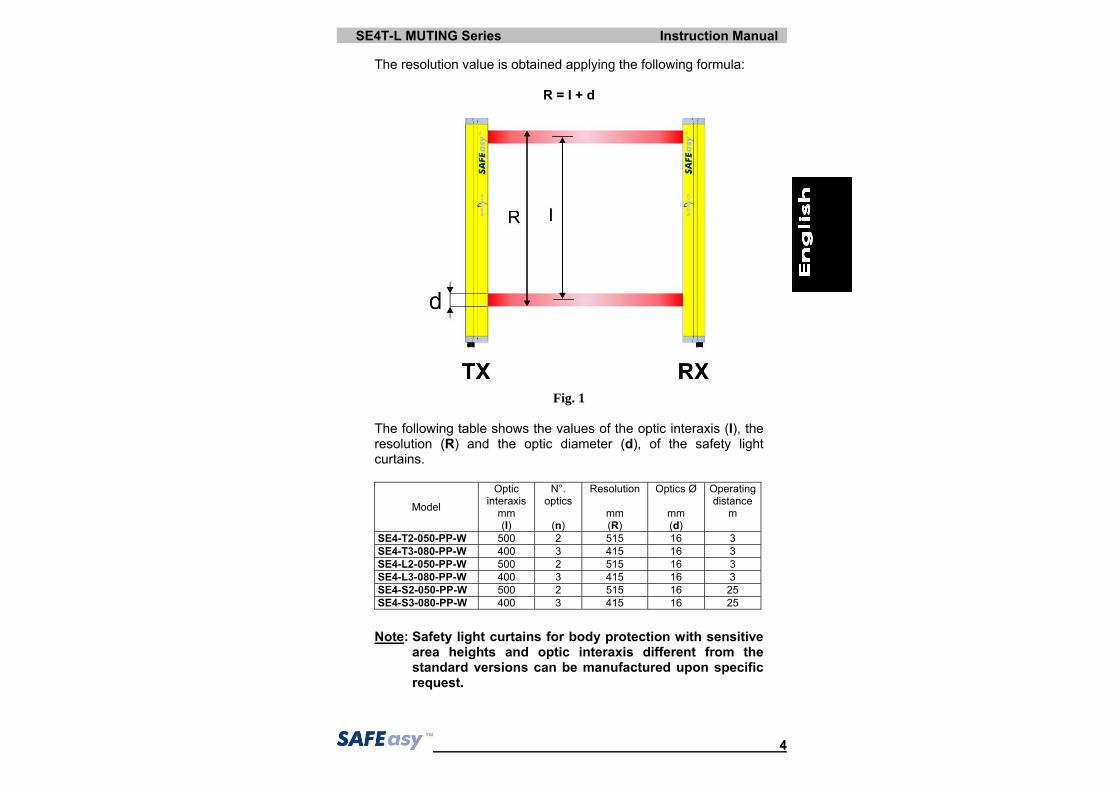
The resolution of the device is the minimum dimension, which an opaque object must have in order to obscure at least one of the beams that constitute the sensitive area. As shown in Fig.1, the resolution only depends on the geometrical characteristics of the lenses, diameter and distance between centres, and is independent of any environmental and operating conditions of the safety light curtain.
SE4T-L MUTING Series Instruction Manual
4
The resolution value is obtained applying the following formula:
R = I + d
Fig. 1 The following table shows the values of the optic interaxis (I), the resolution (R) and the optic diameter (d), of the safety light curtains.
area heights and optic interaxis different from the standard versions can be manufactured upon specific request.
Instruction Manual SE4T-L MUTING Series
5
• The height of the protected area
It is important to distinguish between “Height of the sensitive area” and “Height of the controlled area” (see Fig.2). - The height of the sensitive area is the distance between the
lower and the upper limits respectively of the first and the last lens.
- The height of the controlled area is the effectively protected
area; it delimits the area where an opaque object with larger or equal dimensions respect to the resolution of the safety light curtain may certainly cause the interruption of a beam.
Fig. 2
• The safety distance
It is important to carefully calculate the distance between the point where the safety device will be placed and the possible danger associated with the machine to be protected (see section 2 “Installation mode” for the calculation of the safety distance).
SE4T-L MUTING Series Instruction Manual
6
1.3. Typical applications
The SAFEasyTM safety light curtains of the SE4T-L MUTING series are used in all automation fields where control and protection of the access to dangerous zones is necessary, as well as allowing, by means of the Muting function, material passage inside a dangerous zone during working. In particular they are used to stop the moving mechanical parts in:
In food industry applications, DATASENSOR Technical Service has to verify the compatibility of the material of the safety light curtain housing with any chemical agents used in the production process. The following pictures show some main applications.
L-shaped version with integrated Muting sensors for unidirectional Muting
T-shaped version with integrated Muting sensors for bidirectional Muting
Linear version with external Muting sensors
Instruction Manual SE4T-L MUTING Series
7
1.4. Safety information The following points must be observed for a correct and safe use of the SAFEasyTM safety light curtains of the SE4T-L MUTING series:
• The stopping system of the machine must be electrically controlled.
• This control system must be able to instantly stop the dangerous movement of the machine during all the phases of the working cycle.
• Mounting and connection of the safety light curtain must only be carried-out by qualified personnel, according to the indications included in the special sections (refer to sections 2; 3; 4; 5; 6).
• The safety light curtain must be securely placed in a particular position so that access to the danger zone is not possible without the interruption of the beams (see section 2 “Installation mode”).
• The personnel operating in the dangerous area must be well trained and must have adequate knowledge of all the operating procedures of the safety light curtain.
• The TEST/START button must be located outside the protected area because the operator must check the protected area during all the Test, Override and Reset operations.
• The external signalling lamp of the active Muting must be visible from all operating sides.
• Please carefully respect the mounting instructions for the correct functioning of the Muting devices.
• The function of the external device monitoring (EDM) is active only if the specific wire is correctly connected to the device. Please carefully read the instructions for the correct functioning before powering the light curtain.
SE4T-L MUTING Series Instruction Manual
8
2 INSTALLATION MODE 2.1. Precautions to respect for the choice and installation of the device
• Make sure that the protection level assured by the SAFEasyTM (Type 4) is compatible with the real danger level of the machine to be controlled, according to EN 954-1.
• The outputs (OSSD) of the ESPE must be used as machine stopping devices and not as command devices.
The machine must have its own START command. • The dimension of the smallest object to be detected must be
larger than the resolution level of the ESPE. • The ESPE must be installed respecting the technical
characteristics indicated in section 9. • Do not place the device, in particular the receiving unit, near
intense light sources. • Strong electromagnetic interferences can compromise the correct
functioning of the device. DATASENSOR suggests contacting its own Technical Service when this problem occurs.
The operating distance of the device can be reduced by 50% in the presence of smog, fog or airborne dust.
• A sudden change in environment temperature, with very low minimum peaks, can generate a small condensation layer on the lenses and so jeopardise functioning.
• The Muting function is signalled by a specific Muting signalling lamp. Ensure that the signalling device has sufficient lighting and visibly positioned near the dangerous zone.
• Ensure to correctly use Muting sensors as described in the instructions supplied hereinafter.
Avoid incongruent connections that cannot be controlled and thus excluding undesired potentially dangerous activations.
Instruction Manual SE4T-L MUTING Series
9
2.2. General information on device positioning
2.2.1. Minimum installation distance The safety device must be placed at a specific safety distance (Fig.3). This distance must ensure that the danger zone cannot be reached before the dangerous motion of the machine has been stopped by the ESPE. The safety distance depends on 4 factors, according to the EN-999, 775 and 294 Standards:
1 Response time of the ESPE (the time between the effective beam interruption and the opening of the OSSD contacts).
2 Machine stopping time (the time between the effective opening of the contacts of the ESPE and the real stop of the dangerous movement of the machine).
3 ESPE resolution. 4 Approaching speed of the object to be detected.
Fig. 3
The following formula is used for the calculation of the safety distance:
S = K (t1 + t2) + C where: S = Minimum safety distance in mm. K = Speed of the object, limb or body approaching the dangerous area in mm/sec. t1 = Response time of the ESPE in seconds (see section 9 “Technical data”) t2 = Machine stopping time in seconds. d = Resolution of the system. C = 850 mm for device with resolution > 40mm.
SE4T-L MUTING Series Instruction Manual
10
Note: The value of K is: 2000 mm/s if the calculated value of S is ≤ 500 mm 1600 mm/s if the calculated value of S is > 500 mm When devices with >40 mm resolution are used, the height of the top beam has to be ≥ 900 mm (H2) while the height of the bottom beam has to be ≤ 300 mm (H1).
2.2.2. Minimum distance from reflecting surfaces Reflecting surfaces placed near the light beams of the SAFEasyTM device (over, under or laterally) can cause passive reflections.These reflections can compromise the recognition of an object inside the controlled area (see Fig.4). However, if the RX receiver detects a secondary beam (reflected by the side-reflecting surface) the object might not be detected, even if the object interrupts the main beam.
Fig. 4
Instruction Manual SE4T-L MUTING Series
11
It is thus important to position the safety light curtain according to the minimum distance from reflecting surfaces. The minimum distance depends on:
• Operating distance between emitter (TX) and receiver (RX); • Maximum aperture angle of the light beam emitted by the safety
light curtain, depending on the type of the device; in particular: - 5° for ESPE type 4 (± 2.5° as to the optic axis)
The graphic in Fig.5 shows the data of the minimum distance.
Particularly: d ≥ 100 mm for operating distance 0.5 ÷ 3 m. d ≥ 100 mm + 40 x [operating distance (m) -3] for operating distance ≥ 3 m.
ESPE Type 4
refle
ctin
g su
rface
dis
tanc
e (m
m)
operating distance (m)
SE4T-L MUTING Series Instruction Manual
12
NO
YES
YES
2.2.3. Installation of several adjacent safety light curtains When several safety devices must be installed in adjacent areas, interferences between the emitter of one device and the receiver of the other must be avoided. Fig.6 provides an example of possible interferences between different devices and two pertinent solutions.
Fig. 6
Instruction Manual SE4T-L MUTING Series
13
2.2.4. Use of deviating mirrors The control of any dangerous area, with several but adjacent access sides, is possible using the linear version without integrated Muting sensors and well-positioned deviating mirrors (see section 12 “Accessories”). Fig.7 shows a possible solution to control three different access sides, using two mirrors placed at a 45° angle respect to the beams.
Fig. 7
The operator must respect the following precautions when using the deviating mirrors:
• The alignment of the emitter and the receiver can be a very critical operation when deviating mirrors are used. Even a very small angular displacement of the mirror is enough to loose alignment. A laser pointer (available as an accessory) can be used to avoid this problem.
• The minimum safety distance (S) must be respected for each single section of the beams.
• The effective operating range decreases by about 15% by using only one deviating mirror, the percentage further decreases by using 2 or more mirrors (for more details make refer to the technical specifications of the mirrors used).
• Do not use more than three mirrors for each device. • The presence of dust or dirt on the reflecting surface of the mirror
causes a drastic reduction in the range.
SE4T-L MUTING Series Instruction Manual
14
3. MECHANICAL MOUNTING The emitting (TX) and receiving (RX) bars must be installed with the relevant sensitive surfaces facing each other. The connectors must be positioned on the same side and the distance must be included within the operating range of the model used (see section 9 “Technical data”). Once positioned the two units, the two bars should be aligned and parallel as much as possible. The next step, if necessary, is the fine alignment, as shown in section 5 “Alignment procedures”. To mount the device, use the threaded pins supplied, inserting them into the slots on the two bars (Fig.8 and Fig.9).
Fig.9 In presence of strong vibrations fixing brackets for the Muting arms mounting are compulsory (Fig.10).
Fig.10
Fig. 8
Instruction Manual SE4T-L MUTING Series
15
Fixing brackets can be used where no large mechanical compensation is required during the alignment operation. The rotating supports for the correction of the bar inclination are available on request (see section 12 “Accessories”). In case of applications with particularly strong vibrations, anti-vibration shock absorbers, together with threaded pins, rigid brackets and/or rotating supports, are recommended to reduce the impact of the vibrations, The recommended mounting positions according to the safety light curtain length are shown in the following drawings and table:
MODEL L (mm) A (mm) B (mm) SE4-T2-050-PP-W 642 342 150 SE4-T3-080-PP-W 942 542 200 SE4-L2-050-PP-W 642 342 150 SE4-L3-080-PP-W 942 542 200 SE4-S2-050-PP-W 642 342 150 SE4-S3-080-PP-W 942 542 200
SE4T-L MUTING Series Instruction Manual
16
Fig.11a
Fig.11b
Fig.11c
3.1. Mechanical arm mounting To mount the Muting arms on both the “L’ and “T” version, use the fixing bracket shown in Fig. 11a. This accessory guarantees the perfect alignment of the arms and the perpendicularity respect to the main unit. Position the bracket on the main unit, after having mounted the arm or arms, as shown in Fig. 11b. Verify the correct functioning position and block the group using the two plates and the scews and tightening them with a CH.2.5 allen key (Fig.11c). The following aspects have to be considered during the mechanical arm mounting for the “L” and “T” light curtain models: - Mount the arm with the active Muting
sensors on the receiving unit and the arms with the reflectors on the emitting unit.
- In the “L” version mount the arms in order to intercept the object before entering in the light curtain sensitive area.
- The two arms have to be mounted in order to be the most parallel and aligned possible. The sensors have default alignment, but the rotation around the main arm can be further adjusted by regulating the specific fixing bracket.
- In critical applications due to the presence of strong vibrations, the arms have to be fixed using the specific fixing brackets (Fig.11).
- The use of arms for the Muting function limits the maximum operating distance to 3 meters.
- The Muting arms can be adjusted vertically according to the application and to the connecting cable lengths (typical range is 14 cm).
Instruction Manual SE4T-L MUTING Series
17
4. ELECTRICAL CONNECTIONS All electrical connections to the emitting and receiving units are made through a male M12 connector, located on the lower part of the safety light curtain. A M12 8-pole connector is used for the receiver, a M12 5-pole connector for the Muting sensors and a M12 4-pole connector for the emitter.
RECEIVER (RX):
28
1
5
34
76
+24 Vdc
0 V
OSSD1 PNP
OSSD2 PNP
0 V
+24 Vdc
EDM +24 VdcN.C. external contact
OVR1 +24 VdcN.O. external contact
OVR2 N.O. external contact
3 4
2 1MUTING2
0 V
+24 Vdc
MUTING1
NOT USED
1 = white = TEST/START 2 = brown = +24 Vdc 3 = green = OVERRIDE 1 4 = when = EDM 5 = grey = OSSD1 6 = pink = OSSD2 7 = blue = 0 V 8 = red = OVERRIDE 2
1 = brown = +24 Vdc 2 = white = MUTING2 3 = blue = 0 V 4 = black = MUTING1 5 = grey = NOT USED
EMITTER (TX):
3 4
2 1NOT USED
0 V
+24 Vdc
NOT USED
1 = brown = +24 Vdc 2 = white = NOT USED 3 = blue = 0 V 4 = black = NOT USED
SE4T-L MUTING Series Instruction Manual
18
4.1. Notes on connections For the correct functioning of the SAFEasyTM safety light curtains of the SE4T-L MUTING series, the following precautions regarding the electrical connections have to be respected.
• Use only shielded cables for the connection of the two units. • The light curtain has been developed to offer an adequate
immunity level against disturbances in the most critical working conditions.
• It is possible to connect to ground the device housing using the mechanical part supplied for ground connection (refer to configuration illustrated in Fig.12).
Fig. 12
• Do not place connection cables in contact or near high-voltage
cables (e.g. motor power supplies, inverters, etc.); • Do not connect in the same multi-pole cable the OSSD wires of
different light curtains; • The TEST/START wire must be connected through a N.C. button
to the supply voltage of the ESPE. A daily manual test is necessary to verify the correct functioning of the safety light curtain. Push the specific button to activate the test.
Instruction Manual SE4T-L MUTING Series
19
• The TEST/START button must be located in such a way that the operator can check the protected area during any Test, Override and Reset operation. (see section 6 “Functioning mode”).
• The EDM wire has to be connected to a 24 Vdc normally closed contact, before powering. The monitoring function, if selected, is not activated if at powering the wire is not correctly connected; in this case the light curtain enters in a failure condition.
• The Muting function is activated only if the wires are connected to the sensors, as thus is enable di Mutino lamp integrated on Rx side.
• The device is already equipped with internal overvoltage and
overcurrent suppression devices. The use of other external components is allowed but not recommended. Read the “Functioning mode” section 6 relative to the Muting function, its use and the positioning of the activating sensors.
SE4T-L MUTING Series Instruction Manual
20
Fig. 13
The ground connection of the two units depends on the electrical protection class to be guaranteed (see section 9 “Technical Data” for more information). This connection can be carried-out using the mechanical part supplied for ground connection (see Fig.13). Insert the support plate (M4x0.7 mm threaded holes) in one of the two slots visible laterally on the profile. The two pins (M4x14) have to be screwed on the external support hole, leaving the central hole free. We suggest to screw the pins using a couple included between 2.2 and 2.5 Nm. The Couple guarantees that the pin head passes through the paint allowing the contact with the metal housing. Block the pins using the two M4 self-fixing nuts. The nuts have to be tightened using a hexagonal CH.7 wrench. The nuts avoid the unscrewing of the pins in presence of strong vibrations. Insert the M4 ring and screw it on the central support hole.
Instruction Manual SE4T-L MUTING Series
21
• The OSSD1 and OSSD2 safety contacts cannot be connected in series or in parallel, but can be used separately (Fig.14). If one of these configurations is erroneously used, the device enters into the output failure condition (see cap.7 “Diagnostic functions”).
• Connect both OSSD to the activating device. The avoided connection of an OSSD to the activating device jeopardises the system safety degree that the light curtain has to control.
Fig.14
Fig.15
Fig.16 Fig.17
SE4T-L MUTING Series Instruction Manual
22
5. ALIGNMENT PROCEDURE The alignment between the emitting and the receiving units is necessary to obtain the correct functioning of the light curtain. The alignment is perfect if the optic axes of the first and the last emitting unit’s beams coincide with the optic axes of the corresponding elements of the receiving unit. Two yellow LED indicators (HIGH ALIGN, LOW ALIGN) facilitate the alignment procedure.
5.1. Correct light curtain alignment procedure When the mechanical installation and the electrical connections have been effected – as explained in the previous paragraphs – it is possible to carry-out the alignment of the safety light curtain, according to the following procedure:
• Disconnect the power supply to SAFEasyTM. • Press the TEST/START button and keep it pressed (open the
contact). • Re-connect the power supply. • Release the TEST/START button. • Check the green LED on the bottom of the TX unit (POWER ON)
and the yellow LED (SAFE); if they are ON, the unit is running correctly.
• Verify that one of the following conditions is present on the RX unit:
1. The green LED on the bottom is ON (POWER ON) and the light of the SAFE/BREAK LED on the top is red (BREAK): non-alignment condition.
2. The green LED on the bottom is ON (POWER ON) and the light of the SAFE/BREAK LED on the top is green (SAFE): alignment condition (in this case also the two intermediate yellow LED HIGH ALIGN, LOW ALIGN, are ON).
• Continue with the following steps to change from condition 1 to condition 2:
A Keep the receiving unit in a steady position and set the transmission unit until the yellow LED on the bottom (LOW ALIGN) is ON. This condition shows the effective alignment of the first lower beam.
Instruction Manual SE4T-L MUTING Series
23
B Rotate the transmission unit until the upper yellow LED (HIGH ALIGN) is ON: in this condition the upper LED must change from BREAK to SAFE (from red to green).
Note: Ensure that the green light of the SAFE LED is ON and
steady.
C Delimit the area in which the SAFE LED is steady through some micro adjustments - for the first and then for the second unit - then place both units in the centre of this area.
• Fix the two units firmly using pins and brackets. • Disconnect the power supply to SAFEasyTM. • Re-connect the power supply. • Verify that the green LED is ON on the RX unit (condition where
the beams are free, SAFE) and verify that the same LED turns red if even one single beam is obscured (condition where an object has been detected, BREAK).
SE4T-L MUTING Series Instruction Manual
24
5.2. Correct Muting arm alignment procedure Once effected the safety light curtain alignment and the mechanical arm mounting and the relative connection, ensure the correct alignment of the arm sensors regulating the fixing bracket.
Fig.18 The arm position can be modified vertically and horizontally respect to the main axis. Carefully avoid precarious alignment, controlling the status of the signalling LED, positioned on the active arms. Optimal alignment is reached when all signalling LEDs are OFF.
A slot situated in the front side of the RX unit (Fig. 19), that can be easily opened using a screwdriver, facilitates the access to the internal dip-switches for the configuration of the following functions:
Muting time-out “∞” does not comply with the requirements of IEC 61496-1. Therefore all possible risks must be considered and related precautions undertaken before selecting the “∞”option. The device does not accept configuration changes during normal functioning. A change is accepted only beginning from the successive powering of the device. Particular attention has to be taken during the configuration dip-switch management and use.
Note: For the SE4T-L MUTING devices the top and bottom dip-switches must be configured in the same manner.
6.2. Standard configuration The device is supplied with the following standard configuration: - Muting time-out = 10 min - Muting in the T configuration (4 beams) - EDM deactivated - Automatic Reset Note: The Muting function can be activated only if the Muting1 and
Muting2 inputs and the Muting lamp are correctly operating. The EDM function can be activated only if the specific input is correctly connected to the appropriate device.
For further details of these functions see sections 6.3 and 6.4.
Note: When “L” configuration model is used, is strictly necessary to set dip-switch 2 in OFF position.
1 2 3 4
ON
dip-sw Function ON OFF 1 Muting time-out 10 min. ∞ 2 Muting T config. (4 beams) L config. (2 beams)3 EDM Deactivated Activated 4 Reset Automatic Manual
dip-switches
SE4T-L MUTING Series Instruction Manual
26
6.3. Restart mode An opaque object detected by the beams causes the switching of the OSSD outputs (i.e. the opening of the safety contacts - BREAK condition). The restart of the ESPE (i.e. the closing of the OSSD safety contacts - SAFE condition) can be carried-out in two different ways:
• Automatic Restart: when an opaque object is detected, the ESPE enters in the BREAK condition. Then, after the opaque object has been removed from the controlled area, the ESPE begins its normal functioning again.
• Manual Restart: after the ESPE has detected an opaque object in the controlled area, the light curtain begins its normal functioning again only by pressing the Restart button (TEST button) and after the object has been removed from the controlled area.
Temporal diagram (Manual Restart)
Instruction Manual SE4T-L MUTING Series
27
ON
1 2 3 4
ON
1 2 3 4
Fig.20 below shows the two functioning modes.
AUTOMATIC
RESTART MODE
INTERCEPTED BEAMS
TEST/STARTpush-button
FREE BEAMS
NORMAL FUNCTIONING FREE BEAMS
OSSD OFF OSSD ON
TX TX
RX RX RX
TX
MANUAL RESTART
MODE
BREAK SAFE
OSSD ON
SAFE
OSSD OFF
BREAK
OSSD OFF
BREAK
OSSD ON
SAFE
Fig.20 The selection of the manual/automatic Restart mode is made through the dip–switches placed under the slot of the receiving unit. In particular, the position 4 of both switches must be ON to activate the automatic Restart mode; OFF for the manual Restart mode.
Note: The dip-switches not used for this function are in grey. The lever position of the specific dip-switch is in black (ON) in the automatic Restart mode.
SE4T-L MUTING Series Instruction Manual
28
6.4. Test function The TEST function can be activated by simply pressing the external push-button for at least 0.5 seconds as shown in the following timing diagram. In the previous versions, no timing requirements were specified. AUTOMATIC VERSION
MANUAL VERSION
Instruction Manual SE4T-L MUTING Series
29
6.5. Reset function The light curtain has a Reset function that is activated in presence of an internal failure. The operator has to press the TEST/START button resetting the break condition and thus return to normal functioning. The button has to be kept pressed for at least 5 seconds in one of the following conditions: - output failure; - optic failure; - failure of the Muting signalling device; - failure of EDM test function. Temporal diagram of the Reset function
SE4T-L MUTING Series Instruction Manual
30
6.6. Muting function The Muting sensors must be able to recognise the passing material (pallets, vehicles, …) according to the material’s length and speed. In case of different transport speeds in the Muting area, it is necessary to consider their effect on the total Muting duration.
• The Muting function, excludes the light curtain during functioning, maintaining active the OSSD outputs, according to particular operating requirements (Fig.21).
L-shaped version with integrated Muting sensors for unidirectional Muting
T-shaped version with integrated Muting sensors for bidirectional Muting
Linear version with external Muting sensors
Fig. 21 • The safety light curtain is equipped with two inputs (Muting1 and
Muting2) for the activation of this function, according to the Standards in force.
• This function is particularly suitable when an object, but not a person, has to pass through the dangerous area, under certain conditions.
• It is important to remember that the Muting function represents a forced system condition and therefore has to be use with the necessary precautions.
Instruction Manual SE4T-L MUTING Series
31
• Two Muting sensors activate the Muting1 and Muting 2 inputs. These two sensors should be correctly connected and positioned in order to avoid undesired Muting or potentially dangerous conditions for the operator.
• State of Muting is signalled by Muting Lamp integrated on the top of receiver side.
• During the installation take care to place the Muting Lamp in as visible as possible position.
• If the Muting lamp is broken, the ESPE is blocked. If the Muting lamp is not connected, the Muting or Override request causes the opening of the safety contacts and the device is blocked and the Muting lamp failure is signalled (see 7.4 “Fault and diagnostic messages”).
• Fig. 22 shows an example of Muting functioning:
MUTING OFF MUTING ON MUTING OFF
THE LAMP BLINKS WHEN THE MUTING IS ACTIVATED
OSSD ON
SAFE
OSSD ON
SAFE
OSSD ON
SAFE
Fig. 22
SE4T-L MUTING Series Instruction Manual
32
Temporal diagram of the Muting function for two-sensor configuration ( “L-shaped” or crossed-beam versions)
Temporal diagram of the Muting function for four-sensor configuration (“T-shaped” version)
Instruction Manual SE4T-L MUTING Series
33
6.7. Installation mode of Muting sensors The safety light curtains of the SE4T-L MUTING series have a dip-switch dedicated to the Muting configuration selection.
The requested configuration is obtained using the dip-switches n° 2 present on the receiving unit. With Dip 2 in the ON position, the “T” configuration (4 sensors) is selected. With Dip 2 in the OFF position, the “L” configuration (2 sensor) is selected. Select carefully the configuration, as a wrong configuration can cause the incorrect functioning of the Muting function and a reduction of the safety level.
• The Muting sensors must be positioned in such a way that the activation of the Muting function is not possible with the accidental passing of a person.
• The Muting request can be performed in 2 manners: o activating the two Muting inputs contemporarily; o activating the Muting1 first and then the Muting2, or
viceversa. If the activations occur in sequence, the second activation should occur within 4 sec. after the first; otherwise the Muting will not be activated. Any Muting request can not be made if the ESPE is in the BREAK condition (red LED is ON and the beams are interrupted).
ON
1 2 3 4
1 2 3 4
SE4T-L MUTING Series Instruction Manual
34
6.7.1. SE4-S model Fig.23 provides an installation example of a linear SAFEasyTM light curtain mounted on a conveyor, with the relative external Muting sensors. The A1, A2, B1, B2 Muting activation sensors temporarily inhibit the ESPE if a package passes between the sensors. The outputs of these sensors are connected to the Muting1 and Muting2 inputs of the receiving unit of the ESPE. The contacts of these sensors are controlled by the receiving unit.
Fig. 23
Instruction Manual SE4T-L MUTING Series
35
Optoelectronic, mechanical, proximity sensors etc, can be used as Muting sensors, with closed contact in the presence of the object to be detected. The following are some configuration examples when using the Muting function:
- Application with 4 optoelectronic sensors: parallel-beam configuration The solution is suitable for applications requiring bidirectional movements of objects. For correct functioning, position the dip-switches 2 in the ON position.
A1B1SE
A2B2
Muting sensors connection:
A1 contact
A2 contact
B1 contact
B2 contact
24 Vdc
M12-4 pole connector SE receiver
Pin 2 MUTING 1
Pin 4 MUTING 2
L
V=cost
d1 d1
D
Symbol Unit Formula Min Typ Max Description
D cm L Interaxis between sensors connected to the same Muting input
d1 cm = V * tAB * 100 0.1 Interaxis between sensor A and sensor B
tAB sec Compulsory condition 0.01 4
Activation time of the second sensor after first sensor activation (A B) (B A)
DOA cm d1 + D Distance to respect between adjacent objects to obtain the correct Muting functioning
L cm D Object dimension to activate the Muting function passing between the sensors
V cm/sec = d1 / tAB 250 (suggested)
Object speed to activate the Muting function passing between the sensors
SE4T-L MUTING Series Instruction Manual
36
- Application with 2 optoelectronic sensors: parallel-beam configuration The solution is suitable for applications requiring unidirectional movements of objects. For correct functioning, position the dip-switch 2 in the OFF position. The reset of normal Muting functioning is obtained at a DMoff distance from sensor A.
A B SE
Muting sensors connection:
A contact
B contact
24 Vdc
M12-4 pole connectorSE receiver
Pin 2MUTING 1
Pin 4MUTING 2
L
V=cost.
d1
DMoff Symbol Unit Formula Min Typ Max Description
D1 cm = V * tAB * 100 0.1 Interaxis between sensor A and sensor B
DMoff cm Compulsory condition 33
Distance from sensor A at which the Muting function is deactivated and the light curtain returns to normal functioning
tAB sec Compulsory condition 0.01 4
Activation time of the second sensor after first sensor activation (A B)
tMoff sec = DMoff / V 0.132
(at max. suggested
speed)
8
Time period, referred to sensor A, after which the Muting function is deactivated and the light curtain returns to normal functioning
DOA cm = DMoff 33 Distance to respect between adjacent objects to obtain the correct Muting functioning
L cm d1 Object dimension to activate the Muting function passing between the sensors
V cm/sec = d1 / tAB 4.125 250 (suggested)
Object speed to activate the Muting function passing between the sensors
Instruction Manual SE4T-L MUTING Series
37
6.7.2. SE4-L model
A B SE
Muting sensors connector:
A contact
B contact
24 Vdc
M12-4 pole connectorSE receiver
Pin 2MUTING 1
Pin 4MUTING 2
L
V=cost.
d1
DMoff
The L-configured solution with integrated Muting facilitates sensor installation and suits applications with unidirectional object passage. For correct functioning, position the dip-switch 2 in the OFF position. The reset of normal Muting functioning is obtained at a DMoff distance from sensor A. Symbol Unit Formula Min Typ Max Description
d1 cm Compulsory condition 16.5 Interaxis between sensor A and
sensor B
DMoff cm Compulsory condition 33
Distance from sensor A at which the Muting function is deactivated and the light curtain returns to normal functioning
tAB sec Compulsory condition 0.01 4
Activation time of the second sensor after first sensor activation (A B)
tMoff sec = DMoff / V 0.132
(at max. suggested
speed)
8
Time period, referred to sensor A after which the Muting function is deactivated and the light curtain returns to normal functioning
DOA cm = DMoff 33 Distance to respect between adjacent objects to obtain the correct Muting functioning
L cm d1 Object dimension to activate the Muting function passing between the sensors
V cm/sec = d1 / tAB 4.125 250 (suggested)
Object speed to activate the Muting function passing between the sensors
SE4T-L MUTING Series Instruction Manual
38
6.7.3. SE4-T model
A1B1SEA2B2
Muting sensors connection:
A1 contact
A2 contact
B1 contact
B2 contact
24 Vdc
M12-4 pole connectorSE receiver
Pin 2MUTING 1
Pin 4MUTING 2
L
V=cost.
d1 d1
D
The T-configured solution with integrated Muting facilitates sensor installation and suits applications with bidirectional object passage. For correct functioning, position the dip-switch 2 in the ON position. The reset of normal Muting functioning is obtained at the deactivation of the A2 sensor (or B1 according to the object passage direction).
Symbol Unit Formula Min Typ Max Description
D cm Compulsory condition 34.5
Interaxis between sensors connected to the same Muting input
d1 cm Compulsory condition 16.5 Interaxis between sensor A
and sensor B
tAB sec Compulsory condition 0.01 4
Activation time of the second sensor after first sensor activation (A1 B1) (B2 A2)
tMoff sec = DMoff / V 0.132
(at max. suggested speed)
8
Time period, referred to sensor A2(B1), after which the Muting function is deactivated and the light curtain returns to normal functioning
DOA cm d1 + D = 51
Distance to respect between adjacent objects to obtain the correct Muting functioning
L cm = D 34.5
Object dimension to activate the Muting function passing between the sensors
V cm/sec = d1 / tAB 4.125 250 (suggested)
Object speed to activate the Muting function passing between the sensors
Instruction Manual SE4T-L MUTING Series
39
6.8. Override function This function allows to force a Muting condition when machine reset is necessary, even if one or more beams are interrupted by passing material. The purpose is to clear the protected area of any material accumulated consequently to a failure in the working cycle. For example, if a pallet stops in front of the protected area, the conveyor may not restart as the ESPE (that has one or more interrupted beams) opens the OSSD outputs and will not permit the controlled area clearance. The activation of the Override function makes permits this operation. - Activation of the Override function
• From a lockout condition it is not possible to actuate the override function. When the requirements for the activation are met, a signalling is provided onto the LED display in order to inform users that an override is possible and required.
Two input lines are provided for the override function, OVR1 and OVR2, that must be connected to +24 Vdc and to 0 Vdc respectively by means of two normal open contacts. Standard requires the use of spring return hold-to-run devices or secure momentary action pushbuttons, located so that it will not possible to enter the hazardous zone whilst maintaining the action on devices. Override function can be actuated closing both contacts: whatever contact can be activated first. The maximum out-of-sync interval time allowed is 400 ms, while the minimum one is 0 ms, as shown in the timing diagram.
blinking when override is possible to require override
SE4T-L MUTING Series Instruction Manual
40
While override is actuated, the integrated lamp will be blinking. Override function will automatically terminate when one of the following condition will be given:
• all the muting sensors are de-actuated (*); • the pre-determined time limit has expired; • the requirements for actuation are not met any more
(at least one override input line is deactivated). (*) This is true for light curtains configured as T Muting. For light curtains configured as L Muting, override will terminate when muting sensors are de-actuated AND the light curtain’s beams are free.
• Keep the button pressed until the clearance of the protected area has been completed.
• The maximum length of the Override function is 120 sec. After that time, the ESPE returns to normal functioning, even if the OVERRIDE button is pressed. Obviously, if the button is released within the 120 seconds, the Override function stops immediately.
• When override is de-actuated, the light curtain will return into the normal operation. All possible fault conditions at runtime are shown below.
Fault Cause Action
Contacts out-of-sync: when trying to actuate the override function, the activation timer
expires .
A shortcut to VDC or GND may be present on one of the override input lines or a contact
may be defective.
Override is not actuated: the fault is signalled onto the
LED display. This is not a lockout
condition: the override can be run after fixing the fault.
blinking if contacts are out-of sync or if timeout has expired
fixed RED
Instruction Manual SE4T-L MUTING Series
41
Temporal diagram of the Override function
OVR2
OVR1
Override function
0 ≤ ΔT < 400ms
24Vdc
24Vdc
0V
0V
ON
OFF
SE4T-L MUTING Series Instruction Manual
42
6.9. EDM function The External devices monitoring (EDM) function controls external devices by verifying the OSSD status.
To correctly use this function: - select it using the specific dip-switch - connect EDM input to the 24Vdc N.C.
contact of the device to control.
The function controls the N.C. contact switching according to the changes of the OSSD status.
Tc ≥ 350msec time after the OSSD OFF-ON passage when EDM is carried-out T0 ≥ 100msec time after the OSSD ON-OFF passage when EDM is carried-out
The use of non-conform devices may cause failures. The periodical testing of the function is recommended. The correct dip-switch positioning (dip 3 OFF) for the function activation is shown here aside. 1 2 3 4
1 2 3 4
ON
ON
1 2 3 4
Instruction Manual SE4T-L MUTING Series
43
7. DIAGNOSTIC FUNCTIONS 7.1. Visualisation of the functions
The operator can verify the operating condition of the light curtains through four LEDs positioned on the receiving unit and two LEDs on the emitting unit (Fig.24).
Fig. 24 The meaning of the LEDs positioned on the receiving unit (RX) depends on the light curtain operating mode.
SE4T-L MUTING Series Instruction Manual
44
7.2. Alignment mode In this condition the outputs are OFF.
• SAFE/BREAK LED: SAFE GREEN LED when ON, indicates that no objects have been detected by the device. BREAK RED LED when ON, indicates that the receiving and the emitting units are not aligned, or that an object has been detected.
• ALIGN HIGH LED: (yellow) when ON, indicates the correct alignment of the last TX optic with the corresponding RX optic (top side of the device).
• ALIGN LOW LED: (yellow) when ON, indicates the correct alignment of the first TX optic with the corresponding RX optic (lower side of the device).
• POWER ON LED: (green) when ON, indicates that the unit is correctly powered.
7.3 Operating mode • SAFE/BREAK LED:
SAFE GREEN LED when ON, indicates that no objects have been detected by the device. BREAK RED LED when ON, indicates that one object has been detected; in this condition the outputs are OFF.
• ALIGN HIGH LED: (yellow) when continuously ON, indicates that it is necessary to press the TEST/START button to reset the device consequently to an object interception. This occurs only when the device runs under the manual Reset mode.
• ALIGN LOW LED: (yellow) when blinking, indicates the presence of an output short-circuit. This signalling is only a warning; the device continues to operate. The LEDs located on the emitter (TX) have the following meanings:
• SAFE LED (yellow): when ON, indicates that the unit is emitting correctly.
• POWER ON LED (green): when ON, indicates that the unit is correctly powered.
Instruction Manual SE4T-L MUTING Series
45
7.4. Fault and diagnostic messages The operator is able to check the main causes of the system stop and failure, using the same LEDs used for the visualisation of the functions.
RECEIVING UNIT:
Failure Cause Check and repair
Output failure - Check the output connections. - Check if the load characteristics
are in accordance with the Technical data (see section 9)
Failure of external switching device (EDM test function)
- Control the EDM connections - Check the compatibility of external
switching device with EDM test time
- Switch OFF and switch ON the devices; is failure persists replace external switching device
Microprocessor failure - Check the correct positioning of the configuration dip-switches.
- Switch OFF and switch ON the device; if the failure continues contact DATASENSOR
It’is possible to require Override
- The signalling is NOT a failure. - Activate override to remove material from the protected zone.
Override connection failure.
- Check connections of the override input lines.
Optic failure - Check unit alignment. - Switch OFF and switch ON the
device; if the failure continues contact DATASENSOR
Failure of the integrated Muting signalling lamp
- Switch OFF and switch ON the device; if the failure continues contact DATASENSOR.
SE4T-L MUTING Series Instruction Manual
46
Failure Cause Check and repair
Power supply failure - Check power supply. - If the failure continues contact
DATASENSOR
The power supply voltage is outside the allowed range. Main microprocessor failure
- Check power supply. - Switch OFF and switch ON the
device; if the failure continues contact DATASENSOR
EMITTING UNIT:
Failure Cause Check and repair
Emitter side generic failure
- Check the power supply; if the failure continues contact DATASENSOR and replace both units
Power supply failure - Check the power supply; if the failure continues contact DATASENSOR.
The power supply voltage is outside the allowed range Main microprocessor failure
- Check the power supply; if the failure continues contact DATASENSOR.
Instruction Manual SE4T-L MUTING Series
47
8. CHECKS AND PERIODICAL MAINTENANCE The following is a list of recommended check and maintenance operations that should be periodically carried-out by qualified personnel. Check that: • The ESPE stays locked during beam interruption along the entire
protected area, using the suitable “Test Piece”. • Pressing the TEST/START button, the OSSD outputs should
open (the red BREAK LED is ON and the controlled machine stops).
• The response time at the machine STOP (including response time of the ESPE and of the machine) is within the limits defined by the calculation of the safety distance (see section 2 “Installation Mode”).
• The safety distance between the dangerous areas and the ESPE are in accordance with the instructions included in section 2 “Installation Mode”.
• Access to the dangerous area of the machine from any unprotected area is not possible .
• The ESPE and the external electrical connections are not damaged. The frequency of checks depends on the particular application and on the operating conditions of the safety light curtain.
8.1. Maintenance The SAFEasyTM SE4T-L MUTING safety devices do not require any particular maintenance, with the exception of the cleaning of the protection front surfaces of the optics. When cleaning, use a cotton cloth dampened with water.
Do not under any circumstances use: - alcohol or solvents - wool or synthetic cloths
SE4T-L MUTING Series Instruction Manual
48
8.2. General information and useful data
The safety devices fulfil their safety function only if they are correctly installed, in accordance with the Standards in force. If you are not certain to have the expertise necessary to install the device in the correct way, DATASENSOR Technical Service is at your disposal to carry-out the installation. Auto-regenerating type fuses are used. Consequently, in presence of a short-circuit, these fuses protect the device. After the intervention of the fuses, it is necessary to disconnect the power supply and wait for 20 seconds so that the fuses can automatically restart normal functioning. A power failure caused by interferences may cause the temporary opening of the outputs, but the safe functioning of the light curtain will not be compromised.
8.3. Warranty All appliances are under a 36 month warranty from the manufacturing date. DATASENSOR will not be liable for any damages to persons and things caused by the non-observance of the correct installation modes and device use. The warranty will not cover damages caused by incorrect installation, incorrect use and accidental causes such as bumps or falls. In presence of a non-functioning device, always return the emitting and receiving units for repair or replacement. In presence of failures send the both units to DATASENSOR S.p.A.
9. TECHNICAL DATA Power supply = Vdd: 24 Vdc ± 20% (SELV/PELV) Internal capacitance: 23 nF (Tx) /120 nF (Rx) Emitter consumption (TX) S model: 30 mA max / 0.9W Receiver consumption (RX) S model: 75 mA max (without load) / 2.2W Muting sensor arm consumption: 35 mA max / 1W (with sensors off) Outputs: 2 PNP outputs (2 NPN on request)
short-circuit protection max: 1.4A at 55°C min: 1.1A at -10°C
Output current: 0.5 A max / each output Output voltage - ON min: Vdd –1 V Output voltage - OFF max: 0.2 V Leakage current: < 1mA Capacitive load (pure): 65 nF max at 25°C Resistive load (pure): 56Ω min. at 24 Vdc Response time: 14 ms Emission type: Infrared (880 nm) Resolution: 415 mm (2 optics)
515 mm (3 optics) Operating distance: 0.5…3 m (SE4-T/L)
0.5…25 m (SE4-S) Safety category: Type 4 Auxiliary functions: Muting / Override
Override: 2 minutes Operating temperature: - 10…+ 55 °C Storage temperature: - 25…+ 70 °C Temperature class: T6 (Tx/Rx/Arm) Humidity: 15…95 % (no condensation) Electrical protection: Class 1 (**refer to note) Mechanical protection: IP 65 (EN 60529) Ambient light rejection: IEC-61496-2 Vibrations: 0.35 mm width, 10 … 55 Hz frequency,
20 sweep for each axis, 1octave/min (EN 60068-2-6)
Shock resistance: 16 ms (10 G) 1.000 shock for each axis (EN 60068-2-29)
Reference Standards: IEC 61496-1; IEC 61496-2 Housing material: Painted alluminium (yellow RAL 1003) Cap material: PC MAKROLON Lens material: PMMA Connections: M12-4 pole connector (TX)
M12-8 pole conn. + M12-5 pole conn.(RX) Cable length: 50 m. max (* refer to note)
(with 50nF capactive load and Vdc=24V) Muting signalling device: LED lamp on board Weight: 1.2 Kg max./m of total height
* = if a longer cable has to be used, please verify that the same specifications are respected
** Electrical protection Class 1 Class 3 Protective grounding Compulsory Not accepted Symbol for connection protective grounding Compulsory Not accepted Protection by means of extra-low voltage with protective separation (SELV and PELV)
Recommended Compulsory
SE4T-L MUTING Series Instruction Manual
50
10. LIST OF AVAILABLE MODELS Model
Length of the sensitive area Interaxis N°.
Beams Resolution
(mm) Response time
(ms) Operating
distance (m)
SE4-T2-050-PP-W 515 500 2 515 14 0.5…3 m
SE4-T3-080-PP-W 815 400 3 415 14 0.5…3 m
SE4-L2-050-PP-W 515 500 2 515 14 0.5…3 m
SE4-L3-080-PP-W 815 400 3 415 14 0.5…3 m
SE4-S2-050-PP-W 515 500 2 515 14 0.5…25 m
SE4-S3-080-PP-W 815 400 3 415 14 0.5…25 m
11. DIMENSIONS All the dimensions given are in mm.
35 40
BA
C
35
691 373
MODEL A (mm) B (mm) C (mm) SE4-T2-050-PP-W 120…260 653 690
SE4-T3-080-PP-W 120…260 953 990
SE4-L2-050-PP-W 120…260 653 690
SE4-L3-080-PP-W 120…260 953 990
SE4-S2-050-PP-W - 653 690
SE4-S3-080-PP-W - 953 990
mm
Instruction Manual SE4T-L MUTING Series
51
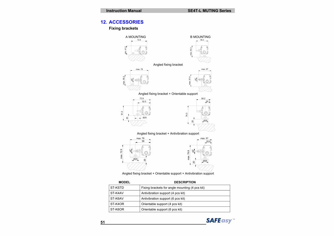
12. ACCESSORIES Fixing brackets
A MOUNTING B MOUNTING
.nim
2.14
.27 8
2.65
3a
m.45.x
Angled fixing bracket
m 7.xa 9
2a
m.05.x
°5±
7m
5.xa4. °5±
.xam 75
Angled fixing bracket + Orientable support
5.25.27 8
50 2Ø2
.162
0
73.4
52Ø2
02 1..65 2
Angled fixing bracket + Antivibration support
02
°5±
m9.27.xa
Ø 52
m85
7.xa 9
5
.m xa6.52
75
8.97.xam
202
Ø
±°5
Angled fixing bracket + Orientable support + Antivibration support
MODEL DESCRIPTION ST-KSTD Fixing brackets for angle mounting (4 pcs kit)
ST-K4AV Antivibration support (4 pcs kit)
ST-K6AV Antivibration support (6 pcs kit)
ST-K4OR Orientable support (4 pcs kit)
ST-K6OR Orientable support (6 pcs kit)
SE4T-L MUTING Series Instruction Manual
52
Deviating mirrors
MODEL DESCRIPTION L1 (mm) L2 (mm) SE-DM 500 Deviating mirror H= 550 mm 554 384 SE-DM 600 Deviating mirror H= 700 mm 704 534 SE-DM 800 Deviating mirror H= 900 mm 904 734 SE-DM 900 Deviating mirror H= 1000 mm 1004 834
Instruction Manual SE4T-L MUTING Series
53
Columns and floor stands
MODEL DESCRIPTION L (mm) X (mm)
SE-S 800 Column and floor stand H= 800 mm 800 30x30
SE-S 1000 Column and floor stand H= 1000 mm 1000 30x30
SE-S 1200 Column and floor stand H= 1200 mm 1200 30x30
SE-S 1500 Column and floor stand H= 1500 mm 1500 45x45
SE-S 1800 Column and floor stand H= 1800 mm 1800 45x45
SE4T-L MUTING Series Instruction Manual
54
Protective stands
Ø6.6 N°2
sp.2 100
86
sm.50x45° N°4
6060
MODEL DESCRIPTION L (mm) SE-P 150 Protective stand H= 273 mm 273
SE-P 300 Protective stand H= 420 mm 420
SE-P 450 Protective stand H= 567 mm 567
SE-P 600 Protective stand H= 714 mm 714
SE-P 750 Protective stand H= 861 mm 861
SE-P 800 Protective stand H= 969 mm 969
SE-P 900 Protective stand H= 1069 mm 1069
SE-P 1050 Protective stand H= 1155 mm 1155
SE-P 1200 Protective stand H= 1302 mm 1369
SE-P 1350 Protective stand H= 1449 mm 1449
SE-P 1500 Protective stand H= 1596 mm 1596
SE-P 1650 Protective stand H= 1743 mm 1743
Instruction Manual SE4T-L MUTING Series
55
Connection cables
MODEL DESCRIPTION CV-A1-22-B-03 Axial shielded 4-pin 3 m cable CV-A1-22-B-05 Axial shielded 4-pin 5 m cable CV-A1-22-B-10 Axial shielded 4-pin 10 m cable CV-A1-22-B-15 Axial shielded 4-pin 15 m cable CV-A1-22-B-25 Axial shielded 4-pin 25 m cable CV-A1-26-B-03 Axial shielded 8-pin 3 m cable CV-A1-26-B-05 Axial shielded 8-pin 5 m cable CV-A1-26-B-10 Axial shielded 8-pin 10 m cable CV-A1-26-B-15 Axial shielded 8-pin 15 m cable CV-A1-26-B-25 Axial shielded 8-pin 25 m cable CV-A2-22-B-03 Radial shielded 4-pin 3 m cable CV-A2-22-B-05 Radial shielded 4-pin 5 m cable CV-A2-22-B-10 Radial shielded 4-pin 10 m cable CV-A2-26-B-03 Radial shielded 8-pin 3 m cable CV-A2-26-B-05 Radial shielded 8-pin 5 m cable CV-A2-26-B-10 Radial shielded 8-pin 10 m cable
Safety relay
The drawing shows the connection between the SAFEasyTM safety light curtain and the Type 4 safety relay of the SE-SR2 series functioning in the automatic Restart mode (left side) and manual Restart with monitoring (right side).
MODEL DESCRIPTION SE-SR2 Type 4 safety relay - 3 NO 1NC
SE4T-L MUTING Series Instruction Manual
56
Laser pointer The laser pointer of the SE-LP series represents a valid alignment and installation support for the SE4T-L MUTING safety light curtain series. The pointer can be moved along the light curtain profile to verify the complete device alignment (top and bottom).
MODEL DESCRIPTION SE-LP Laser pointer
Connection box The SE-SRT connection box facilitates the connection and use of the SE4T-L MUTING safety light curtains. Two force-guided contact relays and extractable clamps to ease cabling are available inside the connection box.