69
SE867-AGPS User Guide 1VV0300860 Rev. 4 - 2010-07-16

SE867-AGPS User Guide 1VV0300860 Rev. 4 - 2010-07-16

SE867-AGPS User Guide 1VV0300860 Rev. 4 - 2010-07-16
Reproduction forbidden without Telit Communications S.p.A. written authorization - All Rights Reserved page 2 of 69
This document is relating to the following products:
PRODUCT
SE867-AGPS

SE867-AGPS User Guide 1VV0300860 Rev. 4 - 2010-07-16
Reproduction forbidden without Telit Communications S.p.A. written authorization - All Rights Reserved page 3 of 69
Contents
1. Introduction ................................................................................................................ 7
1.1. Audience ....................................................................................................................... 7
1.2. Contact Information, Support........................................................................................ 7
1.3. Text Conventions ........................................................................................................... 7
1.4. Related Documents ....................................................................................................... 8
1.5. Document change log.................................................................................................... 8
2. Overview ..................................................................................................................... 9
3. Mechanical Dimensions.............................................................................................10
4. GPS module connections ...........................................................................................12
4.1. PIN-OUT ...................................................................................................................... 12
4.2. Pin-out view ................................................................................................................ 13
5. Electrical description ................................................................................................14
5.1. Available power supply configurations........................................................................ 14 5.1.1. Configuration 1.............................................................................................................................. 14 5.1.2. Configuration 2.............................................................................................................................. 16 5.1.3. Configuration 3.............................................................................................................................. 17
5.2. Power-On Sequence.................................................................................................... 19
5.3. Logic levels ................................................................................................................. 19
6. RF path and antenna .................................................................................................21
6.1. RF design guidelines ................................................................................................... 21
6.2. GPS antenna PCB line guidelines................................................................................ 23
6.3. Antenna installation guidelines................................................................................... 23
7. Connection guidelines ...............................................................................................24
7.1. Reset ........................................................................................................................... 24
7.2. WAKE1......................................................................................................................... 24
7.3. PPS and RTC crystal ................................................................................................... 24
7.4. RFEN and RFXEN ........................................................................................................ 25
7.5. BOOTSEL and flash mode............................................................................................ 25
8. Mounting the SE867-AGPS on the application board .................................................26

SE867-AGPS User Guide 1VV0300860 Rev. 4 - 2010-07-16
Reproduction forbidden without Telit Communications S.p.A. written authorization - All Rights Reserved page 4 of 69
8.1. Stencil ......................................................................................................................... 26
8.2. PCB pad design ........................................................................................................... 26
8.3. Solder paste ................................................................................................................ 28
8.4. SE867-AGPS solder reflow.......................................................................................... 28
9. Moisture sensitivity ...................................................................................................30
10. Software Features .....................................................................................................31
10.1. GPS NMEA ............................................................................................................... 31 10.1.1. Standard NMEA Sentences........................................................................................................... 31 10.1.2. Custom NMEA Sentences ............................................................................................................. 32
10.1.2.1. ASSIST ................................................................................................................................... 33 10.1.2.2. STORELGF............................................................................................................................. 33 10.1.2.3. START.................................................................................................................................... 33 10.1.2.4. SLEEP.................................................................................................................................... 35 10.1.2.5. WAKEUP................................................................................................................................ 36 10.1.2.6. STOP...................................................................................................................................... 36 10.1.2.7. CONFIG.................................................................................................................................. 37 10.1.2.8. SET ........................................................................................................................................ 37 10.1.2.9. GETCONFIG ........................................................................................................................... 37 10.1.2.10. VERSION.............................................................................................................................. 38 10.1.2.11. FOM ..................................................................................................................................... 38 10.1.2.12. SDB ..................................................................................................................................... 38 10.1.2.13. AGC...................................................................................................................................... 39 10.1.2.14. CLKOFFSET......................................................................................................................... 40 10.1.2.15. CFG_R ................................................................................................................................. 41 10.1.2.16. CFG_S.................................................................................................................................. 41 10.1.2.17. ERR...................................................................................................................................... 41 10.1.2.18. OK........................................................................................................................................ 43
10.1.3. Configuration Sections.................................................................................................................. 43 10.1.3.1. Output Configuration............................................................................................................. 43 10.1.3.2. Time Zone Configuration ...................................................................................................... 46 10.1.3.3. Version Number .................................................................................................................... 47 10.1.3.4. Navigation Mode Configuration ............................................................................................ 48 10.1.3.5. SBAS Configuration............................................................................................................... 49 10.1.3.6. 2D Configuration ................................................................................................................... 50 10.1.3.7. Antenna Configuration.......................................................................................................... 52 10.1.3.8. Datum Configuration............................................................................................................. 53 10.1.3.9. Position Pinning Configuration............................................................................................. 56
10.2. Assisted GPS – AGPS ............................................................................................... 58
10.3. Analysis Tool............................................................................................................ 58
11. SE867-AGPS evaluation kit ........................................................................................59
11.1. Short description ..................................................................................................... 59

SE867-AGPS User Guide 1VV0300860 Rev. 4 - 2010-07-16
Reproduction forbidden without Telit Communications S.p.A. written authorization - All Rights Reserved page 5 of 69
12. Conformity assessment issues..................................................................................60
13. Safety recommendations...........................................................................................61
14. Appendix A – Abbreviations and Acronyms................................................................63
15. Appendix B – Datum Codes........................................................................................64

SE867-AGPS User Guide 1VV0300860 Rev. 4 - 2010-07-16
Reproduction forbidden without Telit Communications S.p.A. written authorization - All Rights Reserved page 6 of 69
DISCLAIMER The information contained in this document is proprietary information of Telit Communications S.p.A. and its affiliates (“TELIT”). The contents are confidential and any disclosure to persons other than the officers, employees, agents or subcontractors of the owner or licensee of this document, without the prior written consent of Telit, is strictly prohibited. Telit makes every effort to ensure the quality of the information it makes available. Notwithstanding the foregoing, Telit does not make any warranty as to the information contained herein, and does not accept any liability for any injury, loss or damage of any kind incurred by use of or reliance upon the information. Telit disclaims any and all responsibility for the application of the devices characterized in this document, and notes that the application of the device must comply with the SAFETY standards of the applicable country, and where applicable, with the relevant wiring rules. Telit reserves the right to make modifications, additions and deletions to this document due to typographical errors, inaccurate information, or improvements to programs and/or equipment at any time and without notice. Such changes will, nevertheless be incorporated into new editions of this document. Copyright: Transmittal, reproduction, dissemination and/or editing of this document as well as utilization of its contents and communication thereof to others without express authorization are prohibited. Offenders will be held liable for payment of damages. All rights are reserved. Copyright © Telit Communications S.p.A. 2010.
.

SE867-AGPS User Guide 1VV0300860 Rev. 4 - 2010-07-16
Reproduction forbidden without Telit Communications S.p.A. written authorization - All Rights Reserved page 7 of 69
1. rate and reliable. A. for its use, nor
her rights of third parties which may result from its use. No license is granted by implication or otherwise under any patent rights of Telit
ications S.p.A. other than for circuitry embodied in Telit products. This without notice.
more products in
1.2. tion, Support ntact, technical support, to report documentation errors and to order
manuals, contact Telit’s Technical Support Center (TTSC) at:
Introduction The information presented in this document is believed to be accuHowever, no responsibility is assumed by Telit Communications S.p.any infringement of patents or ot
Commundocument is subject to change
1.1. Audience This document is intended for customers who are evaluating one orthe applicability table.
Contact InformaFor general co
[email protected] [email protected] [email protected] [email protected]
Alternatively, use:
3TUhttp://www.telit.com/en/products/technical-support-center/contact.phpU3T where you can buy the Telit modules or for
ents visit: .comU3T
For detailed information about recommendations on accessories and compon
3TUhttp://www.telit be download from Telit’s official web site Download Zone:
Software Tools can
http://www.telit.com/en/products/download-zone.php. questions contact
t Center (TTSC). Our aim is to make this guide as helpful as possible. Keep us informed of your comments and suggestions for improvements. Telit appreciates feedback from the users of our information.
1.3. Text Conventions
Danger – This information MUST be followed or catastrophic equipment failure or
To register for product news and announcements or for product Telit's Technical Suppor
bodily injury may occur.

SE867-AGPS User Guide 1VV0300860 Rev. 4 - 2010-07-16
Reproduction forbidden without Telit Communications S.p.A. written authorization - All Rights Reserved page 8 of 69
Caution or Warning – Alerts the user to important points about integrating the
er equipment may ion.
ce and suggestions that may be useful when
integrating the module.
01 format, i.e. YYYY-MM-DD.
1.4.
[1] “SE867-AGPS Product description” valuation Board User Guide”
be downloaded from Telit official web site www.telit.com if not wise indicated.
um
module, if these points are not followed, the module and end usfail or malfunct
Tip or Information – Provides advi
All dates are in ISO 86
Related Documents
The following documents are related to this user guide:
[2] “SE867-AGPS E All documentation can other
1.5. Doc ent change log RReevviissiioonn DDaattee
[[yyyyyyyy--mmmm--dddd]] CChhaannggeess
Issue #0 2009-10-23 First release Issue #1 2010-03-11 Added Chap 7 “Connection guidelines”
UART default speed changed to 9600bp Issue #2 2010-04-28 Changed paragraph 7.2
Added paragraph 7.5 Issue #3 Corrected paragraph 5.2 2010-05-10 Paragraph 1.2: added reference to Telit’s Web Site Download Zone
Updated Chapter 10 with firmware 4.0.1 features Changed Appendix A into Appendix B Added Appendix A - Abbreviations and Acronyms
Issue #4 2010-07-16 Updated paragraph 6.1

SE867-AGPS User Guide 1VV0300860 Rev. 4 - 2010-07-16
Reproduction forbidden without Telit Communications S.p.A. written authorization - All Rights Reserved page 9 of 69
2. ed on Telit SE867-
This document cannot embrace the whole hardware solutions and products that may be designed using the SE867-AGPS module. The information given is a guideline and a starting point for proper product development with the Telit stand-alone module.
Overview This document is a user guide for developing a GPS application basAGPS stand-alone GPS module.

SE867-AGPS User Guide 1VV0300860 Rev. 4 - 2010-07-16
Reproduction forbidden without Telit Communications S.p.A. written authorization - All Rights Reserved page 10 of 69
3. Mechanical Dimensions The Telit SE867-AGPS module overall dimensions are: Length: 18 mm Width: 18 mm Thickness: 3.5 mm Weight 1.8 g

SE867-AGPS User Guide 1VV0300860 Rev. 4 - 2010-07-16
Reproduction forbidden without Telit Communications S.p.A. written authorization - All Rights Reserved page 11 of 69
Bottom side

SE867-AGPS User Guide 1VV0300860 Rev. 4 - 2010-07-16
Reproduction forbidden without Telit Communications S.p.A. written authorization - All Rights Reserved page 12 of 69
4. GPS module connections
.1. PIN- T4 OU
Ball Signal I/O Function Type Notes
Misce s Functions llaneou
A1 RFEN O Active high enable signal of R on F secti Control
B1 RFXEN O Active low enable signal of R n F sectio Control
B2 BOOTSEL I Boot mode selection signal Control Internal pull-up
C2 WAKE1 I Wake signal input Control
A3 RTC_IN I Input of the external RTC crystal Timing
A4 RTC_OUT O Output of the external RTC crystal Timing
D2 1V8_RF_EN I Active low enable signal of th RF vol age e 1V8_ tregulator Control Internal pull-up
E2 1V8_DIG_EN I Active low enable signal of the 1V8_DIG voltage regulator Control Internal pull-up
D4 RESET I Active low reset signal Control Schmitt trigger input
F4 RF_IN I RF input RF
B6 PPS O Precise timing signal Timing
UART
B4 TX_UART O UART TX signal UART
B5 RX_UART I UART RX signal UART POWER
D1 1V8_RF PWR RF section power supply -
E1 1V8_DIG PWR BB section power supply -
F1 VIN PWR Internal dual regulator input -
B3 VDD_CTRL PWR CTRL power island supply -
C3 IOVDD_AIN PWR Analog input power island su ply p -
D3 VREG_OUT PWR Output of the internal single tput regulator ou -
A2 VDD_REG_IN PWR Input of the internal single ou ut regulattp or -
A6 V_IO PWR I/O power island supply - GROUND
C1 GND -
F2 GND -
E3 GND -
E4 GND -
A5 GND -
C5 GND -
D5 GND - -
F5 GND - -
E6 GND - -
F6 GND - -
RESERVED
SE867-AGPS User Guide 1VV0300860 Rev. 4 - 2010-07-16
Reproduction forbidden without Telit Communications S.p.A. written authorization - All Rights Reserved page 13 of 69
Ball Signal I/O Function Type Notes
E5 N.C. - -
C6 N.C. - -
D6 N.C. - -
C4 N.C. - -
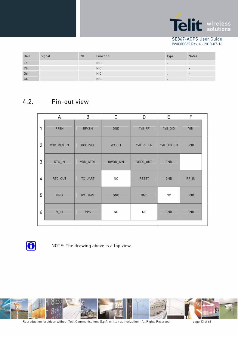
4.2. Pin-out view
A B C D E F
1 RFEN RFXEN GND 1V8_RF 1V8_DIG VIN
2 VDD_REG_IN BOOTSEL WAKE1 1V8_RF_EN 1V8_DIG_EN GND
3 RTC_IN VDD_CTRL IOVD D_AIN VREG_OUT GND
4 RTC_OUT TX_UART NC RESET GND RF_IN
5 GND RX_UART GND GND NC GND
6 V_IO PPS NC NC GND GND
drawing above is a top view. NOTE: The

SE867-AGPS User Guide 1VV0300860 Rev. 4 - 2010-07-16
Reproduction forbidden without Telit Communications S.p.A. written authorization - All Rights Reserved page 14 of 69
5. Electrical description Having power supply circuitry, RF path and board layout properly designed is key to get a successfully application design. So, the below requirements and guidelines have to be carefully read and taken into account for correct device operations.
5.1. Available power supply configurations
In order to give a higher flexibility to the required power configuration, different powering options have been devised:
1) Wide range voltage input from 2.5V up to 4.2V plus an additional 3V 10% reference voltage for I/O peripherals (for 3V logic level interfaces)
2) Wide range voltage input from 2.5V up to 4.2V plus an additional 1.8V 10% reference voltage (internally or externally generated) for I/O peripherals (for 1.8V logic level interfaces)
3) Externally generated 1.8V 5% supply plus 3V 10% or 1.8V 10% for I/O peripherals (bypassing the internal regulator). This solution allows for a lower flexibility but assures lower power consumptions (no dissipation in the internal linear regulator).
5.1.1. Configuration 1
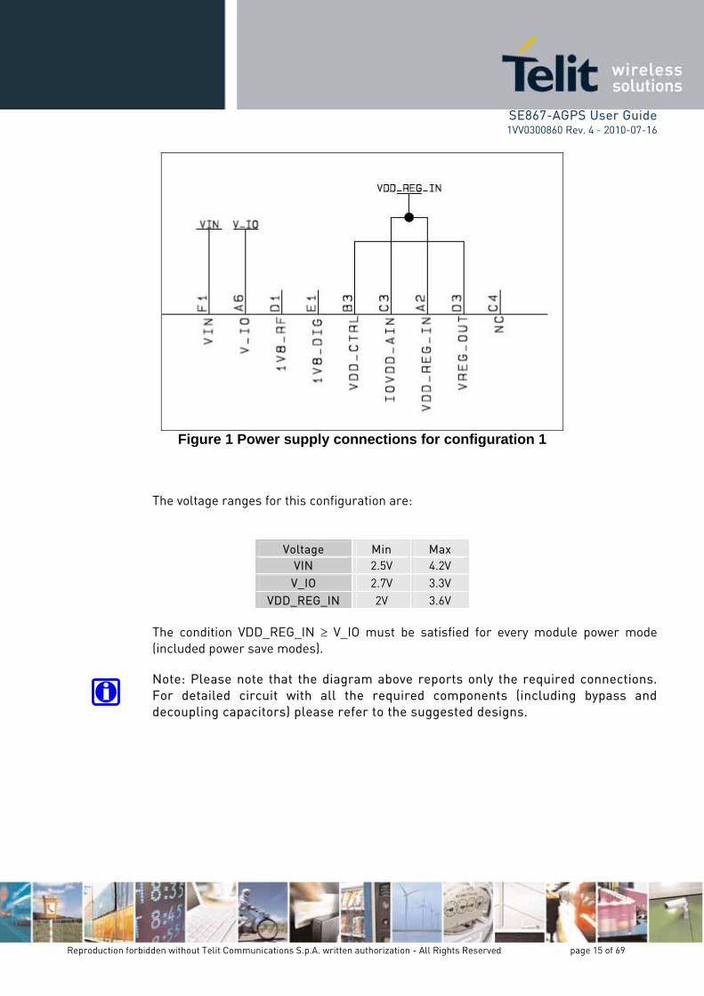
The first available power supply configuration exploits the internal voltage regulators to generate the required 1V8_DIG and 1V8_RF supplies. In order to do so, the internal regulators must be enabled via the 1V8_DIG_EN and 1V8_RF_EN signals (active low). Additional 3V voltage must be supplied on the V_IO pin (this voltage regulate the I/O voltage levels for the UART signals). VDD_REG_IN pin and IOVDD_AIN must be tied together and must be equal to or greater than every other voltage supplied to the internal GPS chipset (they must be compared with V_IO and VDD_CTRL but not with VIN because VIN is internally regulated). VDD_CTRL is responsible of powering the SYSCTRL island and must be connected with the output of the internal regulator (VREG_OUT). SYSCTRL island includes the RFEN, RFXEN and RESET signals, plus the RTC circuitry (so it’s responsible of the system powering during power save modes involving the RTC). The diagram reported in the figure below shows the power connections for this configuration.
SE867-AGPS User Guide 1VV0300860 Rev. 4 - 2010-07-16
Reproduction forbidden without Telit Communications S.p.A. written authorization - All Rights Reserved page 15 of 69
Figure 1 Power supply connections for configuration 1
The voltage ranges for this configu n are:
ratio
Voltage Min Max VIN 2.5V 4.2V V_IO 2.7V 3.3V
VDD_REG_IN 2V 3.6V
The condition VDD_REG_IN V_IO must be satisfied for every module power mode (included power save modes).
Note: Please note that the diagram above reports only the required connections. For detailed circuit with all the required components (including bypass and decoupling capacitors) please refer to the suggested designs.

SE867-AGPS User Guide 1VV0300860 Rev. 4 - 2010-07-16
Reproduction forbidden without Telit Communications S.p.A. written authorization - All Rights Reserved page 16 of 69
5.1.2.
hat the V_IO is now change in the V_IO supply control the t the same logic is
s respecting the condition of IOVDD_AIN being the higher voltage in the system. In this configuration, the internal regulator with input VDD_REG_IN is not exploited in order to have IOVDD_AIN connected to the 1V8_DIG voltage and 1.8V logic levels on the WAKE1 pin. The diagram below indicates the connections required for this configuration.
Configuration 2
This configuration is similar to the previous one with the difference tset to 1.8V and the I/O logic levels have changed consequently. This levels requires also a change in the IOVDD_AIN supply. Indeed this logic level of the WAKE1 pin and so, in order to have all the I/O pin anecessary to change also the IOVDD_AIN configuration, although alway
Figure 2 Power supply connections for configuration 2
The VIN voltage range is the same reported for the previous configuration. Please consider that in place of exploiting the internally generated 1V8_DIG an external 1.8V supply is allowed to be used as well (in this case please verify to have a not noisy and clear 1.8V supply). The voltage range for this external 1.8V supply is 1.62V ÷ 1.98V.
Note: Please note that the diagram above reports only the required connections. For detailed circuit with all the required components (including bypass and decoupling capacitors) please refer to the suggested designs.
SE867-AGPS User Guide 1VV0300860 Rev. 4 - 2010-07-16
Reproduction forbidden without Telit Communications S.p.A. written authorization - All Rights Reserved page 17 of 69
5.1.3.
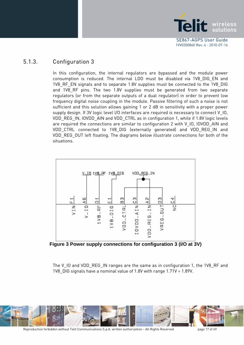
e module power 1V8_DIG_EN and ed to the 1V8_DIG om two separate
der to prevent low uch a noise is not h a proper power
ry to connect V_IO, REG_IN, IOVDD_AIN and VDD_CTRL as in configuration 1, while if 1.8V logic levels
are required the connections are similar to configuration 2 with V_IO, IOVDD_AIN and VDD_CTRL connected to 1V8_DIG (externally generated) and VDD_REG_IN and VDD_REG_OUT left floating. The diagrams below illustrate connections for both of the situations.
Configuration 3
In this configuration, the internal regulators are bypassed and thconsumption is reduced. The internal LDO must be disabled via1V8_RF_EN signals and to separate 1.8V supplies must be connectand 1V8_RF pins. The two 1.8V supplies must be generated frregulators (or from the separate outputs of a dual regulator) in orfrequency digital noise coupling in the module. Passive filtering of ssufficient and this solution allows gaining 1 or 2 dB in sensitivity witsupply design. If 3V logic level I/O interfaces are required is necessaVDD_
Figure 3 Power supply connections for configuration 3 (I/O at 3V)
The V_IO and VDD_REG_IN ranges are the same as in configuration 1, the 1V8_RF and 1V8_DIG signals have a nominal value of 1.8V with range 1.71V ÷ 1.89V.
SE867-AGPS User Guide 1VV0300860 Rev. 4 - 2010-07-16
Reproduction forbidden without Telit Communications S.p.A. written authorization - All Rights Reserved page 18 of 69
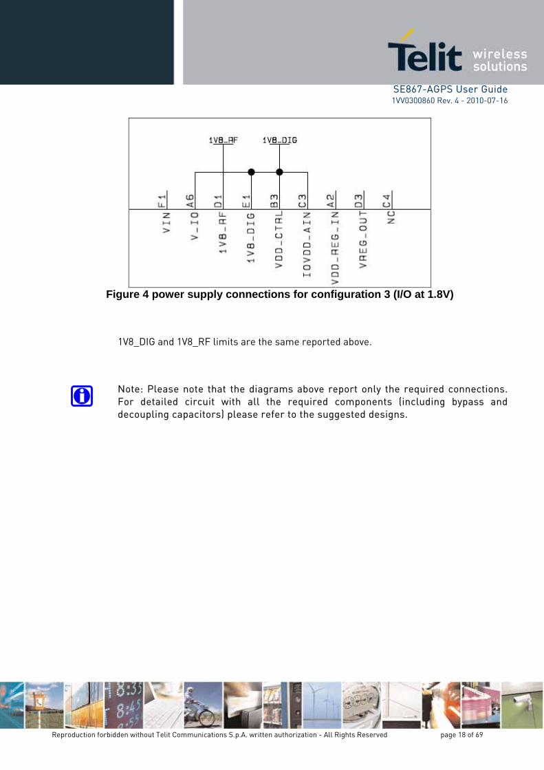
Figure 4 power supply connections for configuration 3 (I/O at 1.8V)
above.
Note: Please note that the diagrams above report only the required connections. For detailed circuit with all the required components (including bypass and decoupling capacitors) please refer to the suggested designs.
1V8_DIG and 1V8_RF limits are the same reported

SE867-AGPS User Guide 1VV0300860 Rev. 4 - 2010-07-16
Reproduction forbidden without Telit Communications S.p.A. written authorization - All Rights Reserved page 19 of 69
5.2.
ule. When using a be paid in order to deed applying 3V
GPS chipset with a er to allow correct ommendations an ntion must be paid ervals. tion. At the power
t signal must be asserted, after the reset signal is received the module is forced in a power-on state and boots up at the negation of the reset signal.
ignal must be asserted also when a power fault is detected in the 1V8_DIG der to avoid conditions which can cause corruption of the internal flash
memory. The reset signal can be asserted by either an external power-on-reset supervisor or a host proce
5.3. Logic levels
Power-On Sequence
A few rules must be respected when powering the SE867-AGPS modconfiguration with a 3V power supply on the V_IO pin attention must avoid asserting V_IO when the 1V8_DIG is not asserted as well. Inwithout the core voltage will cause improper internal biasing of the subsequent large current flow and potential device damage. In ordpower-on of the module and according to the chipset vendor recinternal network on the V_IO power has been inserted. However attein order to avoid asserting V_IO without 1V8_DIG asserted for long intFurthermore, the module requires a power-on reset and fault detecup the active low rese
The reset ssignal in or
ssor.
Digital Signals
Item Condition Min Max Unit
VIH VDDIO 10% 0.7 x
VDDIO V
VIL VDDIO 10%
0.3 x VDDIO V
VOH IOH = -3.5mA @3V 10% VDDIO IOH = -2.25mA @1.8V 10% VDDIO
0.8 x VDDIO VDDIO
V
VOL IOL = 3.5mA @3V 10% VDDIO IOL = 2.25mA @1.8V 10% VDDIO GND
0.2 x VDDIO V
RESET: Schmitt trigger low to high threshold VT+
VDDIO = 1.8V 10% 0.85 1.4 V
RESET: Schmitt trigger high to low threshold VT-
VDDIO = 1.8V 10% 0.53 1.05 V
RESET: Schmitt trigger hysteresis window
VDDIO = 1.8V 10% 0.12 0.64 V
1V8_RF_EN High 1.2 V
1V8_RF_EN Low 0.3 V
1V8_DIG_EN High 1.2 V
1V8_DIG_EN Low 0.3 V

SE867-AGPS User Guide 0300860 Rev. 4 - 2010-07-16
Reproduction forbidden without Telit Communications S.p.A. written authorization - All Rights Reserved page 20 of 69
1VV
Important: in the previous table VDDIO represents the reference voltage of the nt signals. Please refer to the following table for a signal-to-reference
voltage mapping.
differe
Sign er ge mapping al-to-ref ence volta
Signal I/O Reference voltage
RFEN O VDD_CTRL
RFXEN O VDD_CTRL
BOOTSEL I IOVDD_AIN IOVDD_AIN WAKE1 I
RTC_IN I VDD_CTRL
RTC_OUT O VDD_CTRL
RESET I VDD_CTRL
PPS O V_IO
TX_UART O V_IO
RX_UART I V_IO

SE867-AGPS User Guide 1VV0300860 Rev. 4 - 2010-07-16
Reproduction forbidden without Telit Communications S.p.A. written authorization - All Rights Reserved page 21 of 69
6. ions, it is crucial to
is of paramount importance designing the RF path according to the best practices as far as the EMC/EMI and propagation aspects are concerned. Hence, the below requirements and guidelines have to be read and followed
-performing application design.
6.1. nas.
on the RF path is quired to optimize
design, so taking into account typical path losses requirement asks the recommended use in this king of will create a very
formances.
to 30dB, but in this active antenna, avoiding the
use of any additional external LNA. The noise figure must be <1.5dB also in this case and in order to reduce out-of-band jamming and improve GPS performances we recommend using active antennas with additional frequency selectivity (e.g. with an integrated SAW filter) if possible.
The table below reports the main features of the suggested antennas (please note that some features applies only to active antennas):
RF path and antenna When dealing with very low RF signal, as in the case of GPS applicathave a proper PCB layout. In particular it
carefully to have a high
RF design guidelines The SE867-AGPS module can work with both active and passive anten
When working with passive antennas an additional external LNA mandatory. Indeed a >16dB net gain and a <1.5dB noise figure are reperformances of a passive antenna we recommend LNAs featuring gains of 20dB. Even if the path gainfor a gain of 16dB or more it’s important to take into account that value for a RF design based on passive antenna is roughly 16dB, becadesign, due to jamming issues, a gain increase far beyond this limitlow improvement in per
When using an active antenna the RF path gain can be increased up case it’s mandatory concentrating the whole gain in the

SE867-AGPS User Guide 1VV0300860 Rev. 4 - 2010-07-16
Reproduction forbidden without Telit Communications S.p.A. written authorization - All Rights Reserved page 22 of 69
ANTENNA REQUIREMENTS
Central frequency 1575.42 MHz (GPS L1)
Bandwidth 1.023MHz Amplification (active a tenna nonly)
25dB typ. (30dB max)
Noise figure (active antenna only)
< 1.5dB
Impedance [Ohm] 50 Supply voltage (active antenna only)
Depends on customer design
Coupling with other signals is not allowed
The chosen active antenna must be properly biased using a correctly design bias tee. The figure below shows a bias tee example (including ESD protection diode).
Figure 5. Antenna bias tee
ANTENNA LINE ON PCB REQUIREMENTS
Impedance [Ohm] 50 Coupling with other signals is not allowed

SE867-AGPS User Guide 1VV0300860 Rev. 4 - 2010-07-16
Reproduction forbidden without Telit Communications S.p.A. written authorization - All Rights Reserved page 23 of 69
6.2. GPS antenna PCB line guidelines
Ensure that the antenna line impedance is 50 ohm. Keep the antenna line on the PCB as short as possible in order to limit losses. Antenna line must have uniform characteristics (unchanging cross section and
dielectric constant). Meanders and abrupt curves should be avoided. Discontinuity in the PCB GND plane should be avoided. Also, the GND plane should
NOT be used to route any other signal. Surround (on the sides, above and below) the antenna line on PCB with GND, avoid
having other signal tracks facing directly the antenna line track. The ground around the antenna line on PCB has to be strictly connected to the
Ground Plane by placing GND vias every 2mm at least. Place EM noisy devices as far away as possible from SE867-AGPS antenna line. Keep the antenna line far away from the SE867-AGPS power supply lines. If EM noisy devices, such as fast switching ICs, are placed close to the PCB hosting
the SE867-AGPS, the antenna line should be realized in stripline technology (signal trace between the up and down reference GND plan plus a coplanar GND guard trace parallel to the signal trace),or shielded with a metal frame cover.
If EM noisy devices are NOT placed close to the PCB hosting the SE867-AGPS, the antenna line should be realized in microstrip technology (signal trace on the top or bottom layer with only one reference GND plane, plus coplanar GND guard trace parallel to the signal trace), in order to reduce the ohmic losses of the trace.
6.3. Antenna installation guidelines
Install the antenna in a place covered by the GPS signal. Antenna shall not be installed inside metal cases. Antenna shall be installed also according Antenna manufacturer instructions.

SE867-AGPS User Guide 1VV0300860 Rev. 4 - 2010-07-16
Reproduction forbidden without Telit Communications S.p.A. written authorization - All Rights Reserved page 24 of 69
7. Connection guidelines
7.1. Reset
The active low reset signal must be pulled up to VDD_CTRL and controlled in order to have the possibility to assert a reset at the start-up and in case of power fail. To perform a correct reset control the use of a power-on-reset monitoring the 1V8_DIG power supply is recommended, this will allow a correct reset assertion on both power-up and power fail putting the module in the correct working configuration and protecting it from damages. We also suggest providing a manual reset feature in order to have the possibility to bypass the power-on-reset circuit in case of necessity. The manual reset signal can be controlled either with a button or a GPIO coming from the controller.
7.2. WAKE1
WAKE1 is an input signal responsible for the module wake-up from sleep mode. The wake-up functionality is performed simply driving this signal low, in order to avoid the necessity of a GPIO dedicated to this signal it can be connected to the RX_UART so that the module can be woken simply sending data on the RX_UART line. Attention to logic levels compliance between the signals must be paid while connecting RX_UART with WAKE1, indeed the two signals belong to different power islands and have different reference voltages (V_IO for RX_UART and IOVDD_AIN for WAKE1, please refer to paragraph 5.3 for logic levels details).
7.3. PPS and RTC crystal
The PPS signal outputs a precise reference timing pulse with frequency 1Hz and length 100ms. For pulse voltage level please refers to paragraph 5.3.
The SE867-AGPS module requires an external 32.768 kHz crystal connected to RTC_IN and RTC_OUT balls in order to generate the Real Time Clock. The suggested crystal load capacitance and frequency tolerance are reported in the table below:

SE867-AGPS User Guide 1VV0300860 Rev. 4 - 2010-07-16
Reproduction forbidden without Telit Communications S.p.A. written authorization - All Rights Reserved page 25 of 69
Parameter Value Unit
Load capacitance 12.5 pF
Frequency Tolerance 20 ppm
7.4.
dule which can be in normal mode
n the module is in 867-AGPS internal 1 and 2) RFXEN
be connected to the 1V8_RF_EN ball in order to disable the corresponding regulator during sleep mode. When using external regulators the enable of the 1V8_RF
RFXEN or RFEN, based on the enable logic (active high or ce undesired leakage on the RFEN pin we recommend
to RFXEN rather
7.5. ever it is highly
designed so that the SE867 AGPS can be re-flashed onboard, in case the need for an update of the module FW should arise during
re required to be The latest is the
d with a firmware ring normal mode
module in flash mode.
It’s important to avoid supplying V_IO voltage without supplying 1V8_DIG because such a power configuration could cause leakage currents and even damages to the module. At start-up V_IO and 1V8_DIG can be supplied at the same time without any need of a delay network on the V_IO line (such a network has already been implemented inside the module), but V_IO can not be supplied before 1V8_DIG. For the same reasons all the input signals coming to the SE867-AGPS must be driven low when 1V8_DIG is not present.
RFEN and RFXEN
RFEN and RFXEN are output control signal generated from the moused to control power switching. When the module is running operation the RFXEN signal is set to logic 0 and RFEN to logic 1, whesleep RFXEN is logic 1 and RFEN is logic 0. When exploiting the SEregulators to generate 1V8_DIG and 1V8_RF (power configurationsmust
supply must be connected toactive low). In order to reduusing regulators with active low enable logic in order to connect itthan RFEN.
BOOTSEL and flash mode The SE867-AGPS is supplied flashed and fully functional, howrecommended that the application PCB is
the product lifetime.
In order to correctly perform the flashing procedure 4 signals aexternally controlled: TX_UART, RX_UART, Reset and BOOTSEL. control signal used to put the module in flash mode and proceeflashing. The signal has an internal pull-up and can be left floating dufunctioning, driving it low puts the

SE867-AGPS User Guide 1VV0300860 Rev. 4 - 2010-07-16
Reproduction forbidden without Telit Communications S.p.A. written authorization - All Rights Reserved page 26 of 69
8. Mounting the SE867-AGPS on the application board
The Telit SE867-AGPS module has been designed in order to be compliant with a ard lead-free SMT process.
8.1.
es layout can be the same of the recommended footprint (1:1), we suggest a thickness of stencil foil ≥ 120μm.
8.2. PCB pad design
"Non solder mask defined” (NSMD) type is recommended for the solder pads on the PCB.
stand
Stencil
Stencil’s apertur
Recommendations for PCB pad dimensions

SE867-AGPS User Guide 1VV0300860 Rev. 4 - 2010-07-16
Reproduction forbidden without Telit Communications S.p.A. written authorization - All Rights Reserved page 27 of 69
Value [mm] Dimension
Ball pitch 2.4 Solder resist opening diameter A 1,150 Metal PAD diameter B 1 +/- 0,05
Placement of microvias not covered by solder resist is not recommended inside the inhibit area (1.6 mm - red circle in the picture) unless the microvia carry the same signal of the pad itself
Holes in pad are allowed only for blind holes and not for through holes. Recommendations for PCB pad surfaces:
Finish Layer tickness [um] Properties
Electro-less Ni / Immersion Au
3-7 / 0,05-0,15
good solder ability protection, high shear force values
The PCB must be able to resist the higher temperatures, which are occurring at the lead-free process. This issue should be discussed with the PCB-supplier. Generally, the wet-ability of tin-lead solder paste on the described surface plating is better compared to lead-free solder paste.
SE867-AGPS User Guide 1VV0300860 Rev. 4 - 2010-07-16
Reproduction forbidden without Telit Communications S.p.A. written authorization - All Rights Reserved page 28 of 69
8.3. Solder paste
Lead free
Solder paste Sn / Ag / Cu
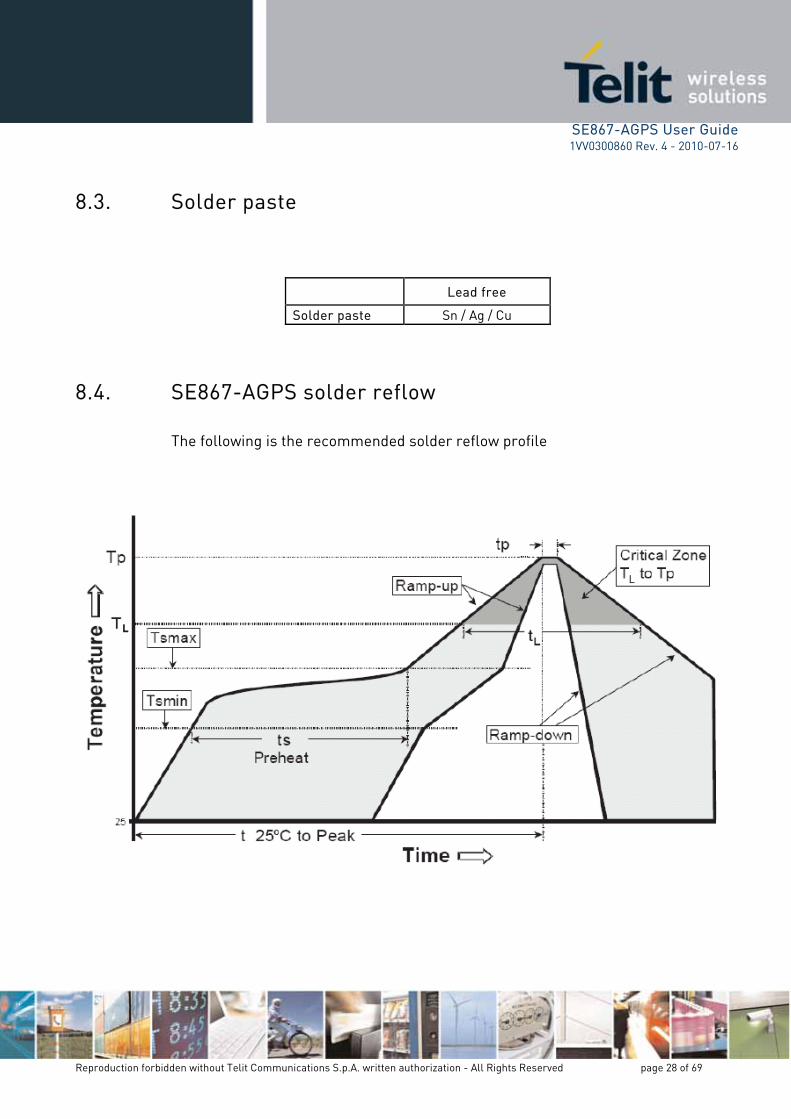
8.4. SE867-AGPS solder reflow
The following is the recommended solder reflow profile

SE867-AGPS User Guide 1VV0300860 Rev. 4 - 2010-07-16
Reproduction forbidden without Telit Communications S.p.A. written authorization - All Rights Reserved page 29 of 69
Profile Feature Pb-Free Assembly
Average ramp-up rate 3 °C / second max (TL to TP) Preheat: - Te - Temp
mperature Min (Tsmin) ax (
max) (
150 °C °C
60-180 seconds erature M
- Time (min toTsmax) 200ts)
Tsmax to TL: ate 3 °C / second max - Ramp-up r
Time maintaned above: erature (TL) 7 °C - Temp
- Time (tL) 2160-150 seconds
Peak Temperature (Tp): 245 + 0/-5 °C Time within 5 °C of actual Peak Temperature (tp) 10-30 seconds Ramp-down rate 6 °C/second max Time 25 °C to Peak Temperature 8 minutes max
NOTE: All temperatures refer to topside of the package, measured on the dy surface.
IMPORTANT: SE867-AGPS module can accept only one reflow process
package bo

SE867-AGPS User Guide 1VV0300860 Rev. 4 - 2010-07-16
Reproduction forbidden without Telit Communications S.p.A. written authorization - All Rights Reserved page 30 of 69
9. S modules is “3”, according with
rements for using
er, the customer has to t f the following conditions: onth from the bag onment of <40°C /
/ 60% RH according to
e maximum time between the opening of the sealed bag and the reflow process shall be 168
Hours if the condition b) “IPC/JEDEC J-STD-033A paragraph 5.2” is respected A baking is required if conditions b) or c) are not respected A baking is required if the humidity indicator inside the bag indicates 10% RH or
more
Moisture sensitivity The level of moisture sensibility of Telit SE867-AGPstandard IPC/JEDEC J-STD-020, take care of all the relative requithis kind of components. Moreov ake care o The shelf life of SE867-AGPS inside of the dry bag shall be 12 m
seal date, when stored in a non-condensing atmospheric envir90% RH
Environmental condition during the production: ≤ 30°C IPC/JEDEC J-STD-033A paragraph 5
Th
SE867-AGPS User Guide 1VV0300860 Rev. 4 - 2010-07-16
Reproduction forbidden without Telit Communications S.p.A. written authorization - All Rights Reserved page 31 of 69
10. er details the standard NMEA supported output messages and describes the
usage of the SE867-AGPS custom NMEA messages.
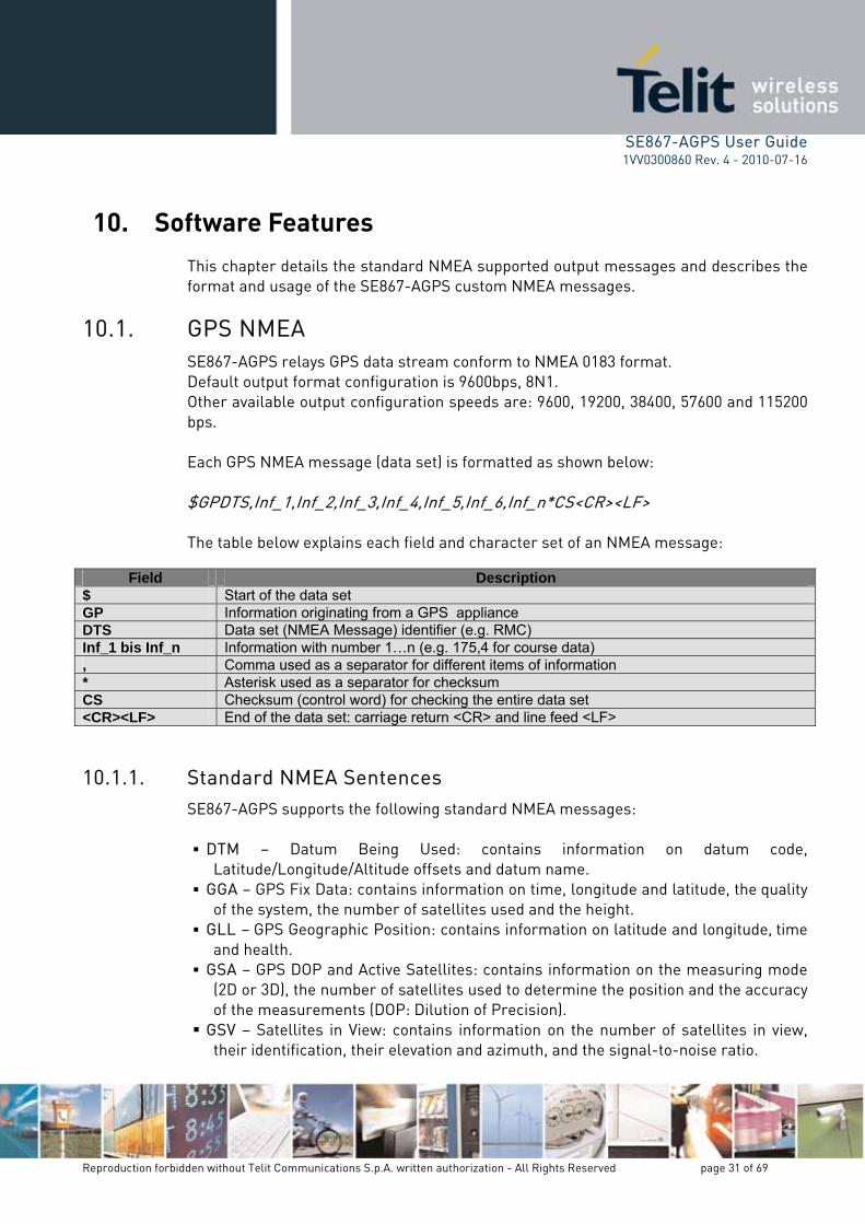
10.1. SE867-AGPS relays GPS data stream conform to NMEA 0183 format.
1. 0, 19200, 38400, 57600 and 115200
Each GPS NMEA message (data set) is formatted as shown below:
f_5,Inf_6,Inf_n*CS<CR><LF>
ter set of an NMEA message:
Software Features This chaptformat and
GPS NMEA
Default output format configuration is 9600bps, 8NOther available output configuration speeds are: 960bps.
$GPDTS,Inf_1,Inf_2,Inf_3,Inf_4,In The table below explains each field and charac
Field Description $ Start of the data set GP Information originating from a GPS appliance DTS Data set (NMEA Message) identifier (e.g. RMC) Inf_1 bis Inf_n Information with number 1…n (e.g. 175,4 for course data) , Comma used as a separator for different items of information * Asterisk used as a separator for checksum CS Checksum (control word) for checking the entire data set <CR><LF> End of the data set: carriage return <CR> and line feed <LF>
10.1.1.
n datum code,
GGA – GPS Fix Data: contains information on time, longitude and latitude, the quality of the system, the number of satellites used and the height.
GLL – GPS Geographic Position: contains information on latitude and longitude, time and health.
GSA – GPS DOP and Active Satellites: contains information on the measuring mode (2D or 3D), the number of satellites used to determine the position and the accuracy of the measurements (DOP: Dilution of Precision).
GSV – Satellites in View: contains information on the number of satellites in view, their identification, their elevation and azimuth, and the signal-to-noise ratio.
Standard NMEA Sentences SE867-AGPS supports the following standard NMEA messages: DTM – Datum Being Used: contains information o
Latitude/Longitude/Altitude offsets and datum name.

SE867-AGPS User Guide Rev. 4 - 2010-07-16
Reproduction forbidden without Telit Communications S.p.A. written authorization - All Rights Reserved page 32 of 69
1VV0300860
RMC – Recommended Minimum Specific GPS Data: contains infla
ormation on time,
ion on course and
ns information on UTC time, date and local time.
0183 standard (http://www.nmea.org) for a deeper description
10.1.2. dard
U mmand/response>*c return><new line>”
‘PUN is command prefix coming first a <com nd/r
titude, longitude and height, system status, speed, course and date. VTG – Course over Ground and Ground Speed: contains informat
speed. ZDA – GPS Time and Date: contai
Please refer to NMEA about information carried by each NMEA data set.
Custom NMEA Sentences SE867-AGPS custom NMEA messages are structured according to the stantemplate of NMEA format:
“$P NV,<co c<carriage
V’ the SE867-AGPS custom ma esponse> field as below:
Command/Respon se In/Out Description
UTC time assistance input mASSIST In essage ST Force immediate LGORELGF In F store operation START In Request for immediate restart SL Request to stop the navigatioEEP In n and enter to sleep mode WA Wake up from KEUP In sleep ST Request to stop the nOP In avigation CONFIG In Request to configure configuration section SET Change configuration in RAM oIn nly GE RequTCONFIG In est to read configure information of configuration section V RequesERSION t Version, alias to PUNV,GETCONFIG,09 InFOM Out Navigation quality indicator (figure-of-merit)
Out Satellites’ data Information SDB Out Automatic gain control debug data AGC
CLKOFFSET Out Master clock offset data CFG_R Out Reply message for read configure information CFG_S Out Reply message for write configure information ERR Out Error message OK Out Success message
Important: Each custom NMEA command shall be sent with an interval of 1s from the ious one. Time interval less than 1s can bear module to work not in a proper way.
prev

SE867-AGPS User Guide 1VV0300860 Rev. 4 - 2010-07-16
Reproduction forbidden without Telit Communications S.p.A. written authorization - All Rights Reserved page 33 of 69
If the NMEA string can be decoded to explicit command for the SE867-AGPS, the same message will be echoed back to sender. According to the NMEA standard the maximum number of characters between the starting delimiter ‘$’ or ‘!’ and the terminating <CR><LF> should be 79, i.e. the maximum buffer size should be 82 for one sentence. For the custom NMEA messages the maximum size of the input messages is 128 characters and for the output messages 200 characters.
10.1.2.1. ASSIST
With ASSIST command the user can inject time assistance into the navigation software. The format of ASSIST command is the following: $PUNV,ASSIST,hhmmss.ss,ddmmyy*cc hhmmss.ss is the UTC time: hh – hours (00…23), mm – minutes (00…59), ss.ss – seconds (00.00…59.99) ddmmyy is the UTC date: dd – day (01…31), mm – month (01…12), yy – year (00…99) $PUNV,ASSIST,tow,wn*cc tow is time of the week in milliseconds (0…604699999) and wn is a week number (starting from January 6, 1980).
10.1.2.2. STORELGF
With STORELGF command the user can force immediate LGF storage. $PUNV,STORELGF*23
10.1.2.3. START
With START command the user can restart the navigation and erase different kind of data at the same time. $PUNV,START,bitmask*cc bitmask is a hexadecimal number (without ‘0x’ prefix) specifying the data to be erased.

SE867-AGPS User Guide 1VV0300860 Rev. 4 - 2010-07-16
Reproduction forbidden without Telit Communications S.p.A. written authorization - All Rights Reserved page 34 of 69
Bitmask Description
0x001 Erase position from NVRAM, FSH and RAM 0x002 Erase accurate time, leave inaccurate time 0x004 Erase RTC time 0x008 Erase TCXO offset and drift values from NVRAM, FSH and RAM 0x010 Erase UTC parameters from FSH and RAM 0x020 Erase ionospheric correction parameters from FSH and RAM 0x040 Erase all almanacs from FSH and RAM 0x080 Erase NVRAM 0x100 Reset configurations from FSH and RAM (Output, Zone, Debug, Datum, VSDSP, pinning) 0x200 Erase all ephemerides from FSH and RAM 0x400 Erase all prehistory information collected so far in FSH and RAM 0x8000 Erase SV configurations
ics to be used with the START command. :
NV
as i particular bitmask.
There is a number of predefined mnemonWhen alias is used the command has the following form $PU ,START,alias*cc ali s a mnemonic specifying the
Alias Bitmask Description
FACTORY 0xFF7F Start-up with no prior information and reset configuration (FSH and RAM) to compiled–in factory defaults
ALL 0x7E7F Same as COLD, but also erase TCXO offset and drift values COLD 0x7E77 Retain TCXO and configurations LGFCOLD 0x7E76 Same as COLD, but retain a position WARM 0x0202 Retain TCXO, position, RTC time and configurations NOTIME 0x0006 Erase time, retain everything else MEDIUM 0x0002 Erase time, but leave RTC HOT 0x0000 Do not erase anything AUTO 0x0000 Do not erase anything
START command in its simplest form is also supported: $PUNV,START*71 ,which just restarts navigation without erasing anything. So effectively it is equal to $PUNV,START,HOT*0E and

SE867-AGPS User Guide 1VV0300860 Rev. 4 - 2010-07-16
Reproduction forbidden without Telit Communications S.p.A. written authorization - All Rights Reserved page 35 of 69
$PUNV,START,AUTO*52 and $PUNV,START,0*6D commands.
10.1.2.4. SLEEP
With the SLEEP command the user can put the system into the sleep mode. The system stays in the sleep mode until it is forced to wake up by activity on UART0 or after a specified timeout. The NMEA command for the sleep mode without timeout is: $PUNV,SLEEP,bitmask*cc bitmask is a hexadecimal number (without ‘0x’ prefix) specifying the data to be erased and has the same set of possible values as for START command described in 10.1.2.3. SLEEP command in its simplest form is also supported: $PUNV,SLEEP*7E ,which effectively equals to $PUNV,SLEEP,0*62 The NMEA command for sleep mode for a predefined time has the following form: $PUNV,SLEEP,hh,mm,ss*cc hh is hours (00…24) mm is minutes (00…59) ss is seconds (00…59). The total sleeping time specified should be less than 90000 seconds. Please note that the specified sleep time determines exactly the period of time, when power consumption of single-chip GPS receiver stays low. If measuring sleep time by watching NMEA stream, it might be several seconds longer due to processing overhead

SE867-AGPS User Guide 1VV0300860 Rev. 4 - 2010-07-16
Reproduction forbidden without Telit Communications S.p.A. written authorization - All Rights Reserved page 36 of 69
in SE867-AGPS firmware, which is related to messages processing, the UART queue flushing delays etc.
10.1.2.5. WAKEUP
To wake up from sleep, the user should send any kind of NMEA message to UART0 port. The content of this message is disregarded by the system. After the wakeup from sleep, the system is always started in auto mode just like if $PUNV, START, AUTO*52 command would be sent. For distinctness sake the following command can be used: $PUNV,WAKEUP*2C
10.1.2.6. STOP
With STOP command the user can stop the navigation and erase different kind of data at the same time. $PUNV,STOP,bitmask*cc bitmask is a hexadecimal number (without ‘0x’ prefix) specifying the data to be erased. It has the same set of possible values as for START command described in 10.1.2.3. The exception is “Reset Configurations from FSH and RAM”, which should not be used with STOP command. There is a number of predefined mnemonics to be used with the STOP command. When alias is used the command has the following form: $PUNV,STOP,alias*cc alias is a mnemonic specifying the particular bitmask. It has the same set of possible values as for START command described in 10.1.2.3. The only exceptions are FACTORY, HOT and AUTO aliases, which are not supported for STOP command. STOP command in its simplest form is also supported: $PUNV,STOP*29 ,which just stops navigation without erasing anything. So effectively it is equal to $PUNV,STOP,0*35

SE867-AGPS User Guide 1VV0300860 Rev. 4 - 2010-07-16
Reproduction forbidden without Telit Communications S.p.A. written authorization - All Rights Reserved page 37 of 69
Please note that the confirmation for STOP command will be echoed only after the system has stopped. Until that time SE867-AGPS will produce navigation data.
10.1.2.7. CONFIG
With CONFIG command the user can change the configuration of the system. The configuration takes effect immediately and it is also stored in non-volatile media. The format of CONFIG command is the following: $PUNV,CONFIG,section ID,Various number of comma separated fields*cc section ID is a decimal number specifying the section ID. It is two fixed decimal digits and the leading zeros are mandatory. The reply to this command is CFG_S sentence described in 10.1.2.16.
10.1.2.8. SET
With SET command the user can change the configuration of the system. The configuration takes effect immediately, but the new configuration is not stored in nonvolatile media. The format of SET command is the following: $PUNV,SET,section ID,Various number of comma separated fields*cc section ID is a decimal number specifying the section ID. It is two fixed decimal digits and leading zeros are mandatory.
10.1.2.9. GETCONFIG
By GETCONFIG command the user can read the configuration of the system. The format of this message is as follows: $PUNV,GETCONFIG,section ID*cc section ID is a decimal number specifying the section ID. It is two fixed decimal digits and the leading zeros are mandatory. Reply to this command is CFG_R sentence described in 10.1.2.15.

SE867-AGPS User Guide 1VV0300860 Rev. 4 - 2010-07-16
Reproduction forbidden without Telit Communications S.p.A. written authorization - All Rights Reserved page 38 of 69
10.1.2.10. VERSION
By VERSION command the user can read version number string. The format of this message is as follows: $PUNV,VERSION*6B The reply to this command is CFG_R sentence described in 10.1.2.15. This command is an alias to the command $PUNV,GETCONFIG,09*48
10.1.2.11. FOM
This message is navigation (PVT) quality indicator, i.e. figure-of-merit. It has the following format: $PUNV,FOM,fom*cc fom an integer number (0…9). Value 0 indicates invalid Fix. Value 1 indicates the poorest Fix quality and value 9 indicates the highest quality. Please see section 10.1.3.1 describing the way how this message can be enabled.
10.1.2.12. SDB
This message provides satellites’ data $PUNV,SDB,GPS,EPHMASK,ALMMASK,RSIVMASK,SIVMASK,IONOFLAG*cc EPHMASK is a bitmask showing for which SVs SE867-AGPS has valid ephemeris data. It has a hexadecimal format with the bit index 0 associated with PRN 1, bit index 1 associated with PRN 2 etc. ALMMASK is a bitmask showing for which SVs SE867-AGPS has valid almanac data. It has a hexadecimal format with the bit index 0 associated with PRN 1, bit index 1 associated with PRN 2 etc. RSIVMASK is a bitmask of SVs for which SE867-AGPS has signal strength information (ones for which it shows signal strength in GSV NMEA sentence). It has a hexadecimal format with the bit index 0 associated with PRN 1, bit index 1 associated with PRN 2 etc.

SE867-AGPS User Guide 1VV0300860 Rev. 4 - 2010-07-16
Reproduction forbidden without Telit Communications S.p.A. written authorization - All Rights Reserved page 39 of 69
SIVMASK is a bitmask of SVs that SE867-AGPS lists in GSV message. It has a hexadecimal format with the bit index 0 associated with PRN 1, bit index 1 associated with PRN 2 etc. IONOFLAG is a Boolean indicator (‘T’ or ‘F’) showing if SE867-AGPS has broadcast ionospheric model. Example: $PUNV,SDB,GPS,80142480,80142480,80142480,80142480,T*cc Please see section 10.1.3.1 describing the way how this message can be enabled.
10.1.2.13. AGC
This message provides an automatic gain control debug data. $PUNV,AGC,I-gain,Q-gain,I-mag,Q-mag,i[1],i[-1],i[3],i[-3],q[1],q[-1],q[3],q[-3], Gain,Rail,Meas,Cnt,Start,Stop*cc I-gain is an RF I-setting value used for driving the RF gain [decibels]. Q-gain is an RF Q-setting value used for driving the RF gain [decibels]. I-mag is the current IF power level for I-channel (in %). Q-mag is the current IF power level for I-channel (in %). I[1] is a [1] bin loading of a sample distribution of the IF/BB signal for I-channel (in %). I[-1] is a [-1] bin loading of a sample distribution of the IF/BB signal for I-channel (in %). I[3] is a [3] bin loading of a sample distribution of the IF/BB signal for I-channel (in %). I[-3] is a [-3] bin loading of a sample distribution of the IF/BB signal for I-channel (in %). Q[1] is a [1] bin loading of a sample distribution of the IF/BB signal for Q-channel (in %). Q[-1] is a [-1] bin loading of a sample distribution of the IF/BB signal for Q-channel (in %).

SE867-AGPS User Guide 1VV0300860 Rev. 4 - 2010-07-16
Reproduction forbidden without Telit Communications S.p.A. written authorization - All Rights Reserved page 40 of 69
Q[3] is a [3] bin loading of a sample distribution of the IF/BB signal for Q-channel (in %). Q[-3] is a [-3] bin loading of a sample distribution of the IF/BB signal for Q-channel (in %). Gain is an amount of gain signals. Rail is an amount of rail signals. Meas is an amount of meas signals. Cnt is a value of a counter that is increased at every gain change on I, Q or both channels. Start is a return value of AGC_start API in GE867-AGPS firmware (0 – success, 1 - failure). Stop is a return value of AGC_stop API in GE867-AGPS firmware (0 – success, -1 - failure). Example: $PUNV,AGC,35,35,51.7,51.7,30.8,33.5,17.3,18.4,30.8,33.5,17.3,18.4,4,0,0,5,0,0*75 Please see section 10.1.3.1 describing the way how this message can be enabled.
10.1.2.14. CLKOFFSET
This message provides the master clock offset data $PUNV,CLKOFFSET,nn.nnnnn,fff.fff*cc nn.nnnnn is a floating point number representing a nominal clock frequency (TCXO frequency) in MHz. fff.fff is a floating point number representing a current clock offset in Hz, in relation to the nominal clock frequency. The current measured absolute clock frequency is then (nn.nnnnn + fff.fff/1e6) in MHz. Example with about 0.5ppm offset over 16.3676MHz nominal clock frequency: $PUNV,CLKOFFSET,16.36760,8.126*cc
SE867-AGPS User Guide 1VV0300860 Rev. 4 - 2010-07-16
Reproduction forbidden without Telit Communications S.p.A. written authorization - All Rights Reserved page 41 of 69
The offset can also be negative, for example: $PUNV,CLKOFFSET,16.36760,-8.126*cc In case of 19.2MHz nominal clock frequency, for example: $PUNV,CLKOFFSET,19.20000,21.427*cc Please see section 10.1.3.1 describing the way how this message can be enabled.
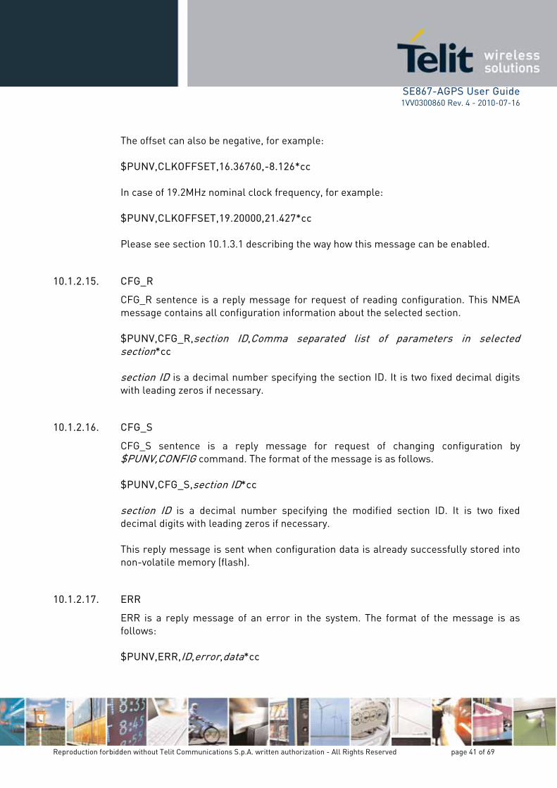
10.1.2.15. CFG_R
CFG_R sentence is a reply message for request of reading configuration. This NMEA message contains all configuration information about the selected section. $PUNV,CFG_R,section ID,Comma separated list of parameters in selected section*cc section ID is a decimal number specifying the section ID. It is two fixed decimal digits with leading zeros if necessary.
10.1.2.16. CFG_S
CFG_S sentence is a reply message for request of changing configuration by $PUNV,CONFIG command. The format of the message is as follows. $PUNV,CFG_S,section ID*cc section ID is a decimal number specifying the modified section ID. It is two fixed decimal digits with leading zeros if necessary. This reply message is sent when configuration data is already successfully stored into non-volatile memory (flash).
10.1.2.17. ERR
ERR is a reply message of an error in the system. The format of the message is as follows: $PUNV,ERR,ID,error,data*cc

SE867-AGPS User Guide Rev. 4 - 2010-07-16
Reproduction forbidden without Telit Communications S.p.A. written authorization - All Rights Reserved page 42 of 69
1VV0300860
ID is the ID of subsystem, which detected the error. Two decimal digits with leading
ith leading zero if sary.
with leading zero if
necessary.
be EA commands.
zero if necessary. error is the subsystem specific error number. Five decimal digits wneces
data is the error specific optional data. Five decimal digits
This document descri s only those error codes that occur with NM
ID Subsyst em Error Data Description
4 AGPS message ID sub-code* AGPS message processing error. Message ID in the error code field specifies which message processing is failed.
5 NMEA 1 0 Illegal command form 5 NMEA 2 0 Illegal command prefix 5 NMEA 3 0 Illegal command 5 NMEA 4 0 Illegal section ID 5 NMEA 5 0 Illegal parameter 5 NMEA 6 0 Illegal CRC 5 NMEA 7 0 Illegal message 7 SAPP 1 sub-code* Reading file data: file open operation is failed 7 SAPP 2 sub-code* Reading file data: file seek operation is failed 7 SAPP 3 sub-code* Reading file data: file read operation is failed 7 SAPP 4 sub-code* Reading file data: file close operation is failed 7 SAPP 5 sub-code* Reading file data: get file size operation is failed 7 SAPP 6 sub-code* Writing data to file: file open operation is failed 7 SAPP 7 sub-code* Filling data into file: file seek operation is failed 7 SAPP 8 sub-code* Filling data into file: file write operation is failed 7 SAPP 9 sub-code* Writing data to file: file seek operation is failed 7 SAPP 10 sub-code* Writing data to file: file write operation is failed 7 SAPP 11 sub-code* Writing data to file: file close operation is failed 7 SAPP 12 sub-code* Memory allocation failed 7 SAPP 13 sub-code* Incoming request is rejected
7 SAPP 14 sub-code* Error detected in the incoming request. Possible reason is the store request for incorrect data.
7 SAPP 15 sub-code* Erase file operation failed 7 SAPP 16 sub-code* Illegal configuration data is detected in the flash.
* sub-code is used for detailed description of error. It is implementation specific code. Examples of error messages:

SE867-AGPS User Guide 1VV0300860 Rev. 4 - 2010-07-16
Reproduction forbidden without Telit Communications S.p.A. written authorization - All Rights Reserved page 43 of 69
Illegal CRC: $PUNV,ERR,05,00006,00000*5B Illegal command: $PUNV,ERR,05,00003,00000*5E
10.1.2.18. OK
OK is an acknowledgement message, which is sent as reply of successful execution of command, which is sent via different protocol than NMEA. The format of the message is as follows: $PUNV,OK,ID,data*cc ID is the ID of responding subsystem. The two decimal digits with leading zero if necessary. data is a protocol specific data. For example, it can be the ID of the successfully executed command: five decimal digits with leading zeros if necessary.
10.1.3. Configuration Sections
10.1.3.1. Output Configuration
The Output configuration is used to configure the input/output protocol. The current output configuration can be read in the system with the following command: $PUNV,GETCONFIG,00*41 The answer is as follows: $PUNV,CFG_R,00,CM-OutCM-In,0,1000,UART,NMEA_MASK*cc The configuration command template for output configuration is as follows: $PUNV,CONFIG,00,CM-OutCM-In,0,1000,UART,NMEA_MASK *cc or

SE867-AGPS User Guide 1VV0300860 Rev. 4 - 2010-07-16
Reproduction forbidden without Telit Communications S.p.A. written authorization - All Rights Reserved page 44 of 69
$PUNV,SET,00,CM-OutCM-In,0,1000,UART,NMEA_MASK *cc
SE867-AGPS User Guide 1VV0300860 Rev. 4 - 2010-07-16
Reproduction forbidden without Telit Communications S.p.A. written authorization - All Rights Reserved page 45 of 69
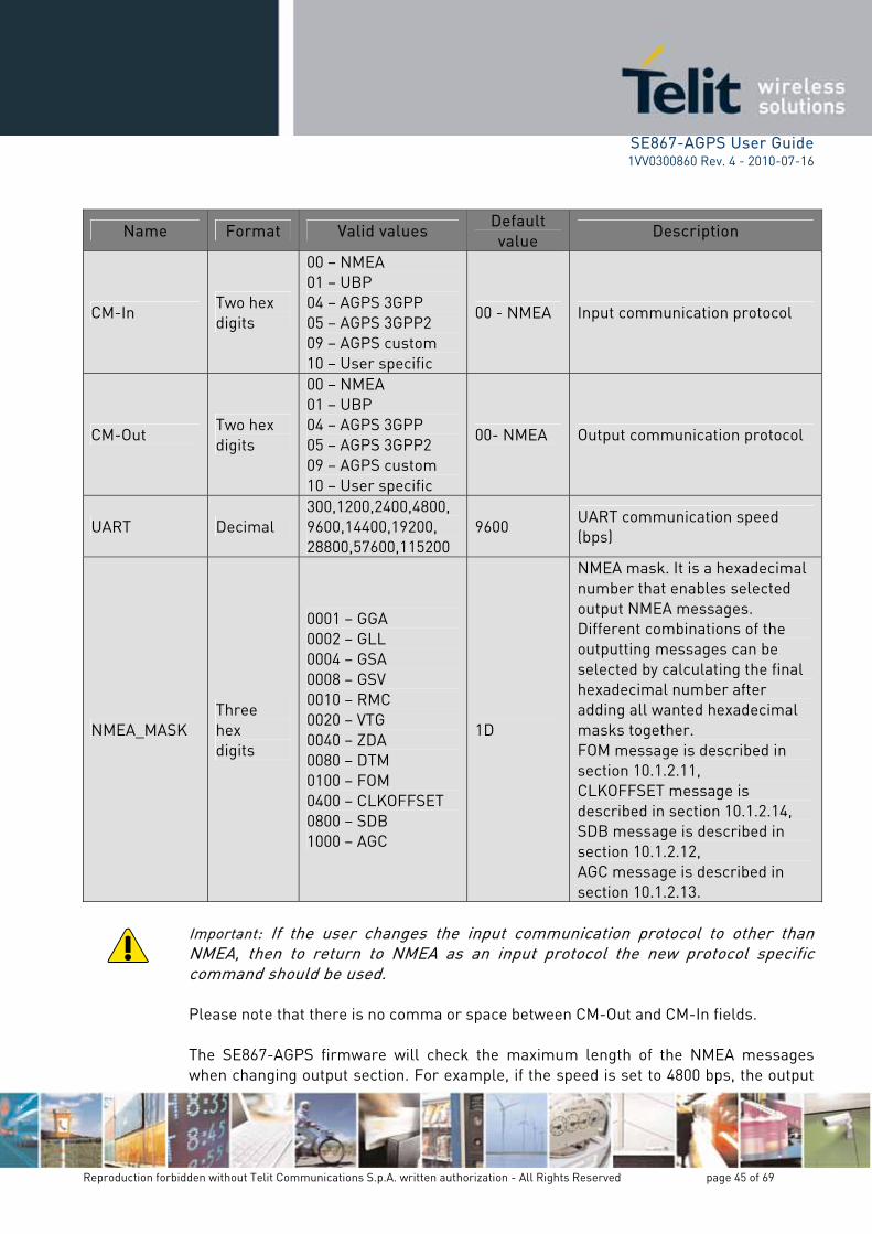
Name Format Valid values Default value
Description
CM-In Two hex digits
00 – NMEA 01 – UBP 04 – AGPS 3GPP 05 – AGPS 3GPP2 09 – AGPS custom 10 – User specific
00 - NMEA Input communication protocol
CM-Out Two hex digits
00 – NMEA 01 – UBP 04 – AGPS 3 GPP05 – AGPS 3 2 GPP09 – AGPS custom 10 – User specific
00- NMEA Output communication protocol
UART Decimal 300,1200,2400,4800, 9600,14400,19200, 28800,57600,115200
9600 UART communication speed (bps)
NMEA_MASK Three hex digits
0001 – GGA 0002 – GLL 0004 – GSA 0008 – GSV 0010 – RMC 0020 – VTG 0040 – ZDA 0080 – DTM 0100 – FOM 0400 – CLKOFFSET 0800 – SDB 1000 – AGC
1D
NMEA mask. It is a hexadecimal number that enables selected output NMEA messages. Different combinations of the outputting messages can be selected by calculating the final hexadecimal number after adding all wanted hexadecimal masks together. FOM message is described in section 10.1.2.11, CLKOFFSET message is described in section 10.1.2.14, SDB message is described in section 10.1.2.12, AGC message is described in section 10.1.2.13.
rtant: If the user changes the input communication protocol to other than
NMEA, then to return to NMEA as an input protocol the new protocol specific command should be used. Please note that there is no comma or space between CM-Out and CM-In fields. The SE867-AGPS firmware will check the maximum length of the NMEA messages when changing output section. For example, if the speed is set to 4800 bps, the output
Impo

SE867-AGPS User Guide 1VV0300860 Rev. 4 - 2010-07-16
Reproduction forbidden without Telit Communications S.p.A. written authorization - All Rights Reserved page 46 of 69
protocol is NMEA and the selected NMEA messages will take bandwidth, which is more than 450 characters per second, the SE867-AGPS firmware will produce an error message and reject the changes. In case of successful execution of $PUNV,CONFIG,00,CM-OutCM-In,0,1000,UART,NMEA_MASK *cc command, the receiver sends confirmation in a following form:
$PUNV,CFG_S,00,00*7F In case of failure of execution of GETCONFIG, CONFIG or SET command the receiver sends the ERR reply message. Please see the ERR section for details (10.1.2.17). Examples: To produce all other messages but DTM and FOM at the speed of 115200 bps: $PUNV,CONFIG,00,0000,0,1000,115200,1C7F*cc To disable the default NMEA messages: $PUNV,CONFIG,00,0000,0,1000,9600,0*cc
10.1.3.2. Time Zone Configuration
The Time Zone configuration is used to configure the user’s localization data. The current configuration can be read in the system by the following command: $PUNV,GETCONFIG,03*42 The answer is as follows: $PUNV,CFG_R,03,HZ,MZ*cc The configuration command template for the Time Zone configuration is $PUNV,CONFIG,03,HZ,MZ*cc or $PUNV,SET,03,HZ,MZ*cc

SE867-AGPS User Guide 1VV0300860 Rev. 4 - 2010-07-16
Reproduction forbidden without Telit Communications S.p.A. written authorization - All Rights Reserved page 47 of 69
Name Format Valid values Default value Description
HZ Decimal -11, -10, -9,...,12 999 (not set)
999 Hour zone. It is an amount of full hour differencefrom the GMT.
MZ Decimal 0, 15, 30, 45 999 (not set)
999 Minute zone. It is an amount of extra minutes over the full hours.
In case of successful execution of $PUNV,CONFIG,03,HZ,MZ*cc command, the receiver sends confirmation in a following form: $PUNV,CFG_S,03*50 In case of failure of execution of GETCONFIG, CONFIG or SET command the receiver sends the ERR reply message. Please see the ERR section for details (10.1.2.17). Examples: To set the -8 hour time zone: $PUNV,CONFIG,03,-8,0*31
10.1.3.3. Version Number
The Version configuration is used to deliver the GE867-AGPS firmware version numbers. If output protocol is NMEA, then version numbers message is also reported after power-on, any commanded start command described in 10.1.2.3 section and after exiting sleep mode. In this case version numbers message is used for notification that SE867-AGPS initialization sequence is complete and it is ready to accept commands. The version numbers can be read by using the following command: $PUNV,GETCONFIG,09*48 The answer is as follows: $PUNV,CFG_R,09,Orion,UBP,BB,Flash,DeviceID,RF-mode,RF-CS,TCXO-PPB,TCXO-Freq*cc Orion is the Orion version string

SE867-AGPS User Guide 1VV0300860 Rev. 4 - 2010-07-16
Reproduction forbidden without Telit Communications S.p.A. written authorization - All Rights Reserved page 48 of 69
version number
BB is the baseband type
Flash is the flash type
ice identifier (hexadecimal number)
e
ct
nds the ERR reply
10.1.3.4. Navigation Mode Configuration
avigation mode configuration is used to configure SE867-AGPS for different use-cases.
GPS supports two navigation modes: PEDESTRIAN and VEHICLE. the configuration parameters described in the sections 10.1.3.5 and
rent navigation mode only.
The current navigation mode configuration can be read in the system with the following o
TCONFIG,11*41
The answer is as follows: $PUNV,CFG_R,11,NavMode,X,X,X,X,X,X,X,X,X,X,X*cc
UBP is the UBP
DeviceID is the dev
RF-mode is RF chip mod
RF-CS is RF IC chip sele TCXO-PPB is the TCXO uncertainty
TCXO-Freq is the TCXO frequency In case of failure of execution of this command the receiver semessage. Please see the ERR section for details (10.1.2.17).
The N
Currently SE867-APlease note that10.1.3.9 are mode specific and changing them affects the cur
c mmand:
$PUNV,GE
Name Format Valid values Default value
Description
NavMode Decimal Number
0,1 1 SE867-AGPS Navigation Mode: 0 – PEDESTRIAN mode 1 – VEHICLE mode
X N/A N/A N/A N/A

SE867-AGPS User Guide 1VV0300860 Rev. 4 - 2010-07-16
Reproduction forbidden without Telit Communications S.p.A. written authorization - All Rights Reserved page 49 of 69
The navigation mode can be switched by the following command $PUNV,CONFIG,NAVMODE,Mode*cc
or
,Mo
$PUNV,SET,NAVMODE
de*cc
Name Format Valid values Default value Description
Mode String PED, VEHICLE VEHICLE SE867-AGPS navigation mode: PED – PEDESTRIAN VEHICLE – VEHICLE
In case of the successful execution of
command, the receiver sends the confirmation in the following form:
command the receiver (10.1.2.17).
10.1.3.5. n
on is used to configure the SBAS functionality. Please note that SBAS configuration through NMEA command affects the current
tion 10.1.3.4 for the navigation models details.
be read in the system with the following command:
NV,GETC FIG,11*41
answer is ollows: $PUNV,CFG_R,11,X,X,X,X,X,X,X,X,Sbas,X,X,X*cc
$PUNV,CONFIG,NAVMODE,Mode*cc
$PUNV,CFG_S,11*53 In case of failure of the execution of GETCONFIG, CONFIG or SET sends the ERR reply message. Please see the ERR section for details
SBAS Configuratio
SBAS configurati
navigation mode only. Please see sec
The current SBAS configuration can $PU ON
The as f
Name Format Valid values Default value Description X N/A N/A N/A N/A
Sbas Decimal Number
0,1 1 SBAS master control: 0 - SBAS is switched off, 1 - SBAS is switched on.
X N/A N/A N/A N/A

SE867-AGPS User Guide 1VV0300860 Rev. 4 - 2010-07-16
Reproduction forbidden without Telit Communications S.p.A. written authorization - All Rights Reserved page 50 of 69
an be switched on or off by following command:
$PUNV,CONFIG,SBAS,Status*cc
or
,SET,S S,Status*
The SBAS functionality c
$PUNV BA cc Name Format Valid values Default value Description
Status String ON, OFF ON SBAS status: ON – SBAS is switched on, OFF- SBAS is switched off.
In case of successful execution of $PUNV,CONFIG,SBAS,Status*cc command, the receiver sends confirmation in a following form: $PUNV,CFG_S,11*53 In case of failure of execution of GETCONFIG, CONFIG or SET command the receiver sends the ERR reply message. Please see the ERR section for details (10.1.2.17).
10.1.3.6. 2D Configuration
The 2D configuration is used to configure SE867-AGPS 2D fix control. The current 2D fix control configuration can be read in the system with the following command: $PUNV,GETCONFIG,11*48 The answer is as follows: $PUNV,CFG_R,11,x,2DControlReacquisition_2DControlAll_2DControlCold,AltAidingVal,StartFallbackTimeout2D,ReacqFallbackTimeout2D,x,x,x,x,x,x,x*cc The SE867-AGPS 2D control can be changed by the following command $PUNV,CONFIG,2D,2DControlReacquisition_2DControlAll_2DControlCold,AltAidingVal,StartFallbackTimeout2D,ReacqFallbackTimeout2D*cc

SE867-AGPS User Guide 1VV0300860 Rev. 4 - 2010-07-16
Reproduction forbidden without Telit Communications S.p.A. written authorization - All Rights Reserved page 51 of 69
or $PUNV,SET,2D,2DControlReacquisition_2DControlAll_2DControlCold,AltAidingVal,StartF Tim D,Re eo
allback eout2 acqFallbackTim ut2D*cc
Name Format Valid
values Default value
Description
X N/A N/A N/A N/A
2DControlReacquisition Hex 0,1 0
Indicates if 2D start-up mode is enabled in reacquisition: 0 – disabled 1 – enabled Please see usage example below.
2DControlAll Hex 0,1 0
Indicates if 2D start-up mode is enabled in all start modes except COLD start: 0 – disabled, 1 – enabled Please see usage examples below.
2DControlCold Hex 0,1 0
Indicates if 2D start-up mode is enabled in COLD start: 0 – disabled, 1 – enabled Please see usage examples below.
AltAidingVal Decimal Number
• 20000 100 Altitude aiding value in respect to geoid (in meters)
StartFallbackTimeout2D Decimal Number
≥ 0 0
SE867-AGPS tries to produce a 3D fix at start-up. If producing a 3D fix is not feasible within this timeout then fallback to 2D fix is tried if allowed by 2DControl…
ReacqFallbackTimeout2DDecimal Number
≥ 0 0
SE867-AGPS tries to produce a 3D fix at reacquisition. If producing a 3D fix is not feasible within this timeout then fallback to 2D fix is tried if allowed by 2DControl…
X N/A N/A N/A N/A In case of successful execution of $PUNV,CONFIG,2D,2DControlReacquisition_2DControlAll_2DControlCold,AltAidingVal,StartFallbackTimeout2D,ReacqFallbackTimeout2D*cc

SE867-AGPS User Guide 1VV0300860 Rev. 4 - 2010-07-16
Reproduction forbidden without Telit Communications S.p.A. written authorization - All Rights Reserved page 52 of 69
command, the receiver sends the confirmation in the following form: $PUNV,CFG_S,11*5A In case of a failure of execution of GETCONFIG, CONFIG or SET command the receiver sends the ERR reply message. Please see the ERR section for details (10.1.2.17). Examples: The default settings: $PUNV,CONFIG,2D,7,100,0,0*cc The default settings plus the enabling of the 2D start-up mode for all start modes only, except COLD start: $PUNV,CONFIG,2D,2,100,0,0*cc The default settings plus the enabling of the 2D start-up mode for the cold start mode only: $PUNV,CONFIG,2D,1,100,0,0*cc
10.1.3.7. Antenna Configuration
The Antenna configuration is used to configure the antenna delay in nanoseconds. It is used for the calibration of PPS accuracy. The current antenna configuration can be read in the system with the following command: $PUNV,GETCONFIG,11*48 The answer is as follows: $PUNV,CFG_R,11,x,x,x,x,x,x,x,AntennaDelay,x,x,x,x*cc

SE867-AGPS User Guide 1VV0300860 Rev. 4 - 2010-07-16
Reproduction forbidden without Telit Communications S.p.A. written authorization - All Rights Reserved page 53 of 69
Name For mat Valid values Default value
Description
X N/A N/A N/A N/A
AntennaDelay Decimal Number
-500…500 0 Antenna cable delay configuration (in nanoseconds)
X N/A N/A N/A N/A The antenna delay can be changed by the following command
T,Delay*cc
Delay*cc
$PUNV,CONFIG,AN
or
$PUNV,SET,ANT,
Name Format Valid values Default value
Description
Delay Decimal Number
-500…500 0
Antenna cable delay configuration (in nanoseconds). Typical cable types such as RF58, RG174 and RG214 cause a delay of 5ns per meter, i.e. the signal propagates in them 20cm in one nanosecond.
In case of successful execution of
in the following form:
of execution of GETCONFIG, CONFIG or SET command the receiver
ply message. Please see the ERR section for details (10.1.2.17).
10.1.3.8. Datum Configuration
The Datum configuration is used to select the output datum. The current configuration can be read in the system by the following command: $PUNV,GETCONFIG,13*43 The answer is as follows:
$PUNV,CONFIG,ANT,Delay*cc command, the receiver sends the confirmation
$PUNV,CFG_S,11*5A
In case of a failuresends the ERR re

SE867-AGPS User Guide 1VV0300860 Rev. 4 - 2010-07-16
Reproduction forbidden without Telit Communications S.p.A. written authorization - All Rights Reserved page 54 of 69
$PUNV,CFG_R,13,Dx,Dy,Dz,Da,Df,Name,Id*cc The configuration command template for custom datum is as follows: $PUNV,CONFIG,13,Dx,Dy,Dz,Da,Df,Name*cc or $PUNV,SET,13,Dx,Dy,Dz,Da,Df,Name*cc To select one of the predefined data, the syntax is as follows: $PUNV,CONFIG,16,Id*cc or $PUNV,SET,16,Id*cc

SE867-AGPS User Guide 1VV0300860 Rev. 4 - 2010-07-16
Reproduction forbidden without Telit Communications S.p.A. written authorization - All Rights Reserved page 55 of 69
Name Format Valid values Default value Description
Dx Decimal -215-1…215-1 0 Datum centre X shift in respect to WGS84 ellipsoid (in meters).
Dy Decimal -215-1…215-1 0 Datum centre Y shift in respect to WGS84 ellipsoid (in meters).
Dz Decimal -215-1…215-1 0 Datum centre Z shift in respect to WGS84 ellipsoid (in meters).
Da
Decimal with fractional part
> 0 6378137 Datum semi-major axis (in meters).
Df Fractional decimal
0…1 0.003352810664 Flattening of datum
Name
String up to 8 characters long
Please see Appendix B – datum c es odfor possible datum names
WGS864 The name of the selected datum
Id Decimal
Please see Appendix B – datum codes for possible Id numbers
1 Identifier of a predefined datum
In case of successful execution of $PUNV,CONFIG,13,Dx,Dy,Dz,Da,Df,Name*cc and $PUNV,CONFIG,16,Id*cc commands, the receiver sends confirmation in a following form: $PUNV,CFG_S,13*51 In case of failure of execution of GETCONFIG, CONFIG or SET command the receiver sends the ERR reply message. Please see the ERR section for details (10.1.2.17). Examples:
Default settings:

SE867-AGPS User Guide 1VV0300860 Rev. 4 - 2010-07-16
Reproduction forbidden without Telit Communications S.p.A. written authorization - All Rights Reserved page 56 of 69
$PUNV,CONFIG,16,1*0D
10.1.3.9. Position Pinning Configuration
The Position pinning configuration is for static case parameter configuration. Please note that the position pinning configuration through NMEA command affects the current navigation mode only. Please see section 10.1.3.4 for the navigation modes details. The current configuration can be read in the system by the following command: $PUNV,GETCONFIG,17*47 The answer is as follows: $PUNV,CFG_R,17,Position threshold,Velocity threshold,Position update timeout,Deep mode delay*cc The configuration command template for control configuration is as follows: $PUNV,CONFIG,17,Position threshold,Velocity threshold,Position update timeout,Deep mode delay*cc or $PUNV,SET,17,Position threshold,Velocity threshold,Position update timeout,Deep mode delay*cc

SE867-AGPS User Guide 1VV0300860 Rev. 4 - 2010-07-16
Reproduction forbidden without Telit Communications S.p.A. written authorization - All Rights Reserved page 57 of 69
Name Format Valid
values
Default value
(pedestrian)
Default value
(vehicle) Description
Position Threshold
Decimal with fractional part
≥ 0 0 50
The threshold value for position jump. Position pinning will be disabled if this value is reached (in meters). Zero values for position and velocity thresholds effectively mean that position pinning is disabled.
Velocity Threshold
Decimal with fractional part
≥ 0 0 1
The threshold value for velocity calculation. Position pinning will be disabled if this value is reached (in meters per second). Zero values for position and velocity thresholds effectively mean that position pinning is disabled.
Position update timeout
Decimal > 0 1 120
In position pinning mode, pinned position is updated based on this timeout (in seconds).
Deep mode delay
Decimal ≥ 0 0 600
When in position pinning mode, deep pinning mode is activated after this delay (in seconds). If 0, then deep pinning mode is disabled.
$PUNV,CONFIG,17,Position threshold,Velocity threshold,Position update timeout,Deep mode delay*cc command, the receiver sends confirmation in the following form: $PUNV,CFG_S,17*55 In case of failure of execution of GETCONFIG, CONFIG or SET command the receiver sends the ERR reply message. Please see the ERR section for details (10.1.2.17).
In case of successful execution of

SE867-AGPS User Guide 1VV0300860 Rev. 4 - 2010-07-16
Reproduction forbidden without Telit Communications S.p.A. written authorization - All Rights Reserved page 58 of 69
10.2. up navigation in
locations where llite signals are obscured. AGPS can also accelerate the navigation
lable, by quickly securing location information from non-broadcast sources, thus reducing power consumed in
h mode. 6a_SE867-AGPS_Assisted_GPS_Application_Note for details.
10.3. o connect the GPS
, for visualizing and analyzing the NMEA received data. lyzer can be downloaded from Telit’s Download Zone (see 1.2).
software tool will allow users to view:
ta (2D/3D Fix, Latitude, Longitude, Altitude, Speed, Heading, TTFF, Date, Time, HDOP, VDOP, PDOP)
History Signal Strength NMEA Output Stream
: In this tool the baud rate of the Virtual COM Port connection must be set to
Assisted GPS – AGPS SE867-AGPS supports Assisted GPS (AGPS) technology to speedchallenging environments: indoors, urban canyons and other broadcast sateprocess in conditions where broadcast ephemeris is avai
satellite searcSee 80000nt1003
Analysis Tool Telit suggests using Orion Analyzer; a Windows® application used treceiver via RS-232 to a PCOrion AnaThis Navigation Da
Position Plot Sky Plot
NOTE9600bps.

SE867-AGPS User Guide 1VV0300860 Rev. 4 - 2010-07-16
Reproduction forbidden without Telit Communications S.p.A. written authorization - All Rights Reserved page 59 of 69
11. SE867-AGPS evaluation kit
11.1. Short description
In order to give the customer the possibility to evaluate the performances of Telit SE867-AGPS module in all the available configurations, an evaluation kit has been developed.
The evaluation kit consists in a single board with:
SE867-AGPS module
Mini USB connector for power supply and data communication with a PC
FTDI chip for USB to UART conversion
SMA RF connector for optional external active antenna or instrument connection
On board passive antenna + LNA (currently non available, future use only)
DIP switches for configuration options selection
Thanks to the onboard FTDI chip the USB connection is seen as a Virtual COM Port by the PC after the installation of the FTDI VCP drivers (available for free at http://www.ftdichip.com/Drivers/VCP.htm).
All the customer needs to work with this evaluation board is a PC to connect with the evaluation kit and software to perform NMEA data flow reading and position fixing (e.g. Visual GPS, available for free in Internet).

SE867-AGPS User Guide 1VV0300860 Rev. 4 - 2010-07-16
Reproduction forbidden without Telit Communications S.p.A. written authorization - All Rights Reserved page 60 of 69
12. onformity assessment issues
ssential requirements of
he following European Union Directives:
Directive 2004/108/EEC for conformity for EMC
ements SE867-AGPS module is compliant s:
Matters (ERM). Standard: EN 300 440-2 (v1.2.1)
EMC (Electromagnetic Compatibility). Standards: EN 301 489-1 and EN 301 489-3 (1.4.1)
LVD (Low Voltage Directive) Standards: EN 60 950 (2005)
C
Assessment of the final product must be made against the ethe EMC and the LVD Directives. The SE867-AGPS module is conform to t
Low Voltage Directive 2006/95/EEC and product safety
In order to satisfy the essential requirwith the following standard
Electromagnetic compatibility and Radio spectrum

SE867-AGPS User Guide 1VV0300860 Rev. 4 - 2010-07-16
Reproduction forbidden without Telit Communications S.p.A. written authorization - All Rights Reserved page 61 of 69
13. Safety recommendations READ CAREFULLY
Make sure that the use of this product is allowed in the country and in the environment where used. The use of this product may be dangerous and has to be avoided in the following areas:
Where it can interfere with other electronic devices in environments such as hospitals, airports, aircrafts, etc
Where there is risk of explosion such as gasoline stations, oil refineries, etc
It is responsibility of the user to enforce the country regulation and the specific environment regulation
Do not disassemble the product; any mark of tampering will compromise the warranty validity.
We recommend following the instructions of the hardware user guides for a correct wiring of the product. The product has to be supplied with a stabilized voltage source and the wiring has to be conforming to the security and fire prevention regulations.
The product has to be handled with care, avoiding any contact with the pins because electrostatic discharges may damage the product itself.
The system integrator is responsible for the functioning of the final product; therefore, care has to be taken to the external components of the module, as well as of any project or installation issue, because of the risk of disturbing external networks or devices or having impact on the security. Should there be any doubt, please refer to the technical documentation and the regulations in force.
Every module has to be equipped with a proper antenna with specific characteristics. The antenna has to be installed with care in order to avoid any interference with other electronic devices. The European Community provides some Directives for the electronic equipments introduced on the market. All the relevant information’s are available on the European Community website: http://ec.europa.eu/enterprise/sectors/rtte/documents/

SE867-AGPS User Guide 1VV0300860 Rev. 4 - 2010-07-16
Reproduction forbidden without Telit Communications S.p.A. written authorization - All Rights Reserved page 62 of 69
The text of the Directive 99/05 regarding telecommunication equipments is available, while the applicable Directives (Low Voltage and EMC) are available at: http://ec.europa.eu/enterprise/sectors/electrical/lvd/index_en.htm

SE867-AGPS User Guide 1VV0300860 Rev. 4 - 2010-07-16
Reproduction forbidden without Telit Communications S.p.A. written authorization - All Rights Reserved page 63 of 69
14. Appendix A – Abb ons and Acronyms reviatiAcronym Description
AEUI Almanac, Ephemeris, UTC and Ionospheric AGC Automatic Gain Controls AGPS Assisted GPS ASCII American Standard Code for Information Interchange bps Bits Per Second CRC Cyclic Redundancy Check ESP Ephemeris Self Prediction FOM Figure Of Merit FSH Flash memory GMT Greenwich Mean Time GPS Global Positioning System HW Hardware ID Identifier LGF Last Good Fix LSE Least Square Estimation N/A Not Applicable NMEA The National Marine Electronics Association NVRAM Non Volatile RAM PVT Position-Velocity-Time Ppb Parts per billion Ppm Parts per million PPS Pulse Per Second PRN Pseudo Random Noise. Identifier for SV. RAIM Receiver Autonomous Integrity Monitoring RAM Random Access Memory RF Radio Frequency RTC Real Time Clock SAPP Storable Application Profile Subsystem SBAS Satellite Based Augmentation System SDK Software Development Kit SV Space Vehicle. Another name for satellite. TCXO Temperature Controlled Crystal Oscillator TOW Time Of Week UART Universal Asynchronous Receiver / Transmitter UBP u-Nav Binary Protocol UTC Universal Time Coordinated VSDSP VLSI Solution DSP WGS84 World Geodetic System reference frame for the earth, for use in geodesy and navigation

SE867-AGPS User Guide 1VV0300860 Rev. 4 - 2010-07-16
Reproduction forbidden without Telit Communications S.p.A. written authorization - All Rights Reserved page 64 of 69
15. Appendix B – Datu s m CodeID NMBR NAME Region of use 0 0 User defined 1 WGS84 Global 2 ADI-M Ethiopia; Sudan 3 ADI-E Burkina Faso 4 ADI-F Cameroon 5 ADI-A Ethiopia 6 ADI-C Mali 7 ADI-D Senegal 8 ADI-B Sudan 9 AFG Somalia 10 AIN-A Bahrain 11 AIN-B Saudi Arabia 12 AMA American Samoa Islands 13 ANO Cocos Islands 14 AIA Antigua (Leeward Islands) 15 ARF-A Botswana 16 ARF-H Burundi 17 ARF-B Lesotho 18 ARF-C Malawi 19 ARF-M MEAN FOR Botswana; Lesotho; Malawi; Swaziland; Zaire; Zambia; Zimbabwe 20 ARF-D Swaziland 21 ARF-E Zaire 22 ARF-F Zambia 23 ARF-G Zimbabwe 24 ARS-M MEAN FOR Kenya; Tanzania 25 ARS-A Kenya 26 ARS-B Tanzania 27 ASC Ascension Island 28 ATF Iwo Jima 29 SHB St Helena Island 30 TRN Tern Island 31 ASQ Marcus Island 32 AUA Australia; Tasmania 33 AUG Australia; Tasmania 34 PHA Djibouti 35 IBE Efate & Erromango Islands 36 BER Bermuda 37 BID Guinea-Bissau 38 BOO Colombia 39 BUR Indonesia (Bangka & Belitung Ids) 40 CAZ Antarctica (McMurdo Camp Area)

SE867-AGPS User Guide 1VV0300860 Rev. 4 - 2010-07-16
Reproduction forbidden without Telit Communications S.p.A. written authorization - All Rights Reserved page 65 of 69
41 CAI Argentina 42 CAO Phoenix Islands 43 CAP South Africa 44 CAC Bahamas; Florida 45 CGE Tunisia 46 CHI New Zealand (Chatham Island) 47 CHU Paraguay 48 COA Brazil 49 DAL Guinea 50 DID Deception Island; Antarctica 51 BAT Indonesia (Sumatra) 52 GIZ New Georgia Islands (Gizo Island) 53 EAS Easter Island 54 EST Estonia 55 EUR-E Cyprus 56 EUR-F Egypt 57 EUR-G England; Channel Islands; Scotland; Shetland Islands 58 EUR-K England; Ireland; Scotland; Shetland Islands 59 EUR-C Finland; Norway 60 EUR-B Greece 61 EUR-H Iran 62 EUR-I Italy (Sardinia) 63 EUR-J Italy (Sicily) 64 EUR-L Malta
65 EUR-M
MEAN FOR Austria; Belgium; Denmark; Finland; France; W Germany; Gibraltar; Greece; Italy; Luxembourg; Netherlands; Norway; Portugal; Spain; Sweden; Switzerland
66 EUR-A MEAN FOR Austria; Denmark; France; W Germany; Netherlands; Switzerland 67 EUR-S MEAN FOR Iraq; Israel; Jordan; Lebanon; Kuwait; Saudi Arabia; Syria 68 EUR-D Portugal; Spain 69 EUR-T Tunisia 70 EUS MEAN FOR Austria; Finland; Netherlands; Norway; Spain; Sweden; Switzerland 71 FOT Nevis; St. Kitts (Leeward Islands) 72 GAA Republic of Maldives 73 GEO New Zealand 74 GRA Azores (Faial; Graciosa; Pico; Sao Jorge; Terceira) 75 GUA Guam 76 GSE Indonesia (Kalimantan) 77 DOB Guadalcanal Island 78 HEN Afghanistan 79 HER Croatia-Serbia, Bosnia-Herzegovina 80 HJO Iceland 81 HKD Hong Kong 82 HTN Taiwan 83 IND-B Bangladesh 84 IND-I India; Nepal

SE867-AGPS User Guide 1VV0300860 Rev. 4 - 2010-07-16
Reproduction forbidden without Telit Communications S.p.A. written authorization - All Rights Reserved page 66 of 69
85 IND-P Pakistan 86 INF-A Thailand 87 ING-B Vietnam (Con Son Island) 88 ING-A Vietnam (Near 16øN)
89 INH-A1 Thailand
90 IDN Indonesia 91 IRL Ireland 92 ISG South Georgia Islands 93 IST Diego Garcia 94 JOH Johnston Island 95 KAN Sri Lanka 96 KEG Kerguelen Island 97 KEA West Malaysia & Singapore 98 KUS Caroline Islands 99 KGS South Korea 100 LCF Cayman Brac Island 101 LEH Ghana 102 LIB Liberia 103 LUZ-A Philippines (Excluding Mindanao) 104 LUZ-B Philippines (Mindanao) 105 MPO Gabon 106 MIK Mahe Island 107 MAS Ethiopia (Eritrea) 108 MER Morocco 109 MID Midway Islands 110 MIN-A Cameroon 111 MIN-B Nigeria 112 ASM Montserrat (Leeward Islands) 113 NAH-A Oman (Masirah Island) 114 NAH-C Saudi Arabia 115 NAH-B United Arab Emirates 116 NAP Trinidad & Tobago 117 NAS-D Alaska (Excluding Aleutian Ids) 118 NAS-V Alaska (Aleutian Ids East of 180øW)
119 NAS-W Alaska (Aleutian Ids West of 180øW)
120 NAS-Q Bahamas (Except San Salvador Id) 121 NAS-R Bahamas (San Salvador Island) 122 NAS-F Canada (Alberta; British Columbia) 123 NAS-H Canada (manitoba; Ontario) 124 NAS-G Canada (New Brusnick; Newfoundland; Nova Scotia; Quebec) 125 NAS-I Canada (Northwest Territories; Saskatchewan) 126 NAS-J Canada (Yukon) 127 NAS-O Canal Zone 128 NAS-T Cuba

SE867-AGPS User Guide 1VV0300860 Rev. 4 - 2010-07-16
Reproduction forbidden without Telit Communications S.p.A. written authorization - All Rights Reserved page 67 of 69
129 NAS-U Greenland (Hayes Peninsula)
130 NAS-P MEAN FOR Antigua; Barbados; Barnuda; Caicos Islands; Cuba; Dominican Republic; Grand Cayman; Jamaica; Turks Islands
131 NAS-N MEAN FOR Belize; Costa Rica; El Salvador; Guatemala; Honduras; Nicaragua 132 NAS-E MEAN FOR Canada 133 NAS-C MEAN FOR CONUS
134 NAS-A MEAN FOR CONUS (East of Missisipi River including Louisiana; Missouri; Minnesota)
135 NAS-B MEAN FOR CONUS (West of Missisipi River excluding Louisiana; Missouri; Minnesota)
136 NAS-L Mexico 137 NAR-A Alaska (Excluding Aletuian Ids) 138 NAR-E Aleutian Ids 139 NAR-B Canada 140 NAR-C CONUS 141 NAR-H Hawaii 142 NAR-D Mexico; Central America 143 NSD Algeria 144 FLO Azores (Corvo & Flores Islands) 145 OEG Egypt 146 OHA-A Hawaii 147 OHA-B Kauai 148 OHA-C Maui
149 OHA-M MEAN FOR Hawaii; Kauai; Maui; Oahu
150 OHA-D Oahu 151 FAH Oman 152 OGB-A England 153 OGB-B England; Isle of Man; Wales
154 OGB-M MEAN FOR England; Isle of Man; Scotland; Shetland Islands; Wales
155 OGB-C Scotland; Shettland Islands 156 OGB-D Wales 157 PLN Canary Islands 158 PIT Pitcairn Island 159 PTB MEAN FOR Burkina faso & Niger 160 PTN Congo 161 POS Porto Santo; Madeira Islands 162 PRP-A Bolivia 163 PRP-B Chile (Northern; Near 19øS) 164 PRP-C Chile (Sourthern; Near 43øS) 165 PRP-D Colombia 166 PRP-E Ecuador 167 PRP-F Guyana
168 PRP-M
MEAN FOR Bolivia; Chile; Colombia; Ecuador; Guyana; Peru; Venezuela

SE867-AGPS User Guide 1VV0300860 Rev. 4 - 2010-07-16
Reproduction forbidden without Telit Communications S.p.A. written authorization - All Rights Reserved page 68 of 69
169 PRP-G Peru 170 PRP-H Venezuela 171 HIT Chile (Near 53øS) (Hito XVIII) 172 PUR Puerto Rico; Virgin Islands 173 PUK Russia 174 QAT Qatar 175 QUO Greenland (South) 176 REU Mascarene Islands 177 EUR-I Italy (Sardinia) 178 SPK-A Hungary 179 SPK-B Poland 180 SPK-C Czechoslovakia 181 SPK-D Latvia 182 SPK-E Kazakhstan 183 SPK-F Albania 184 SPK-G Romania 185 CCD Czechoslovakia (Prior 1 JAN 1993) 186 SAE Espirito Santo Islands 187 SAO Azores (Sao Miguel; Santa Maria Ids) 188 SAP East Falkland Islands 189 SCK Namibia 190 SGM Salvage Islands 191 SRL Sierra Leone 192 SAN-A Argentina 193 SAN-B Bolivia 194 SAN-C Brazil 195 SAN-D Chile 196 SAN-E Colombia 197 SAN-F Ecuador 198 SAN-J Ecuador (Baltra; Galapagos) 199 SAN-G Guyana
200 SAN-M
MEAN FOR Argentina; Bolivia; Brazil; Chile; Colombia; Ecuador; Guyana: Paraguay; Peru; Trinidad & Tobago; Venezuela
201 SAN-H Paraguay 202 SAN-I Peru 203 SAN-K Trinidad & Tobago 204 SAN-L Venezuela 205 SOA Singapore 206 TAN Madagascar 207 TIL Brunei; E. Malaysia (Sabah Sarawak) 208 TOY-A Japan 209 TOY-M MEAN FOR Japan; South Korea; Okinawa 210 TOY-C Okinawa 211 TOY-B South Korea 212 TDC Tristan da Cunha 213 MVS Fiji (Viti Levi Island)

SE867-AGPS User Guide 1VV0300860 Rev. 4 - 2010-07-16
Reproduction forbidden without Telit Communications S.p.A. written authorization - All Rights Reserved page 69 of 69
214 VOR Algeria 215 WAK Wake Atoll 216 ENW Marshall Islands 217 WGS72 Global Definition 218 YAC Uruguay 219 ZAN Suriname 220 - Reserved 221 KKJ Finland


