UNO 2004 Cliff Whitcomb October 21, 2004 1 Sea Connector Family and Seabase Architecture Systems Engineering & System Architecture Presentation to Naval Postgraduate School SI4000 Fall AY2005 Project Seminar October 21, 2004 Dr. Cliff Whitcomb [email protected]
University of New OrleansNaval Architecture and Marine Engineering
UNO 2004 Cliff WhitcombOctober 21, 2004 3
Outline• Systems Engineering• System Architecture• Sea Connector Project
– DOE/RSM process
UNO 2004 Cliff WhitcombOctober 21, 2004 4
Systems Engineering
• Systems Engineering - an interdisciplinary approach and means to enable the realization of successful systems. (INCOSE Handbook)
UNO 2004 Cliff WhitcombOctober 21, 2004 5
Definitions• System - An interacting combination
of elements to accomplish a defined objective. These include hardware, software, firmware, people, information, techniques, facilities, services, and other support elements. (INCOSE)
• System - A group of interacting, interrelated, or interdependent elements forming a complex whole. (American Heritage® Dictionary of the English Language)
• Engineering - The application of scientific and mathematical principles to practical ends such as the design, manufacture, and operation of efficient and economical structures, machines, processes, and systems. (American Heritage®
Dictionary of the English Language)
UNO 2004 Cliff WhitcombOctober 21, 2004 6
Systems Engineering
Source: The Institute for Systems Research, U of Maryland, College
Park, MD
• Systems engineering - The application of scientific and mathematical principles to the design, manufacture, and operation of efficient and economical combinations of interacting elements that accomplish a defined objective.
Systems engineering finds its focus in constructs of
synthesis and analysis for problems involving multiple aspects of the real world.
UNO 2004 Cliff WhitcombOctober 21, 2004 7
Systems Engineering Approach
System Requirements Definition
System Requirements Allocation
Performance Requirements
Top Level Design
Detailed Design
FabricationCoding
Unit Tests
Hardware/Software Integration Tests
Hardware/Software Production Test and Evaluation
Integrated Hardware/Software Acceptance Test
Operational Test and Evaluation
System Definition and Design Hardware/Software Definition and Design Hardware/Software Implementation Hardware/Software Test System Integration Test
Validation
Verification
Verification
Verification
Verification
UNO 2004 Cliff WhitcombOctober 21, 2004 8
What is a Systems Engineer?• Defines, Develops, and Deploys Solutions
– Use systems engineering processes• Roles
– Involved in design from day one– As “system developer”
• Employ SE techniques for development– As “customer support organization”
• Provide SE oversight and management
• Supports Decision Making– Use quantitative and qualitative formulation,
analysis, and interpretation to determine impacts of alternatives
UNO 2004 Cliff WhitcombOctober 21, 2004 9
Systems Engineer Responsibilities• Lead Proactively at System Level
– Maintain system perspective• Support Decision Making
– Provide factual recommendations• Enforce Program Decision Making
Discipline• Serve as Chief Communicator and
Honest Broker• Be Guarantor of Success
UNO 2004 Cliff WhitcombOctober 21, 2004 10
Dimensions to SE• Education (Academia)• Practice (Organizations)
– Capabilities– Effectiveness
• Knowledge (Critical Thinking and Research)– Creation of Knowledge– Think Differently– Discovery of Principles?
• Profession– International Council on Systems Engineering
(INCOSE) www.incose.org– Certification
Holis
tic V
iew
UNO 2004 Cliff WhitcombOctober 21, 2004 11
Systems Engineering Trends• Corporations Want ‘it’ (SE) Now
– Organizational Focus• Expansion and Diffusion of Fundamentals
– From disciplinary specialization to generalization• Life Long Learning
– Field is ill defined and dynamic– Discovery is continuous (discontinuities exist, however)– Incorporate projects and case studies (since current
learning not always shared)Education is that which remains
when one has forgotten everything he learned in school.
- Albert Einstein
UNO 2004 Cliff WhitcombOctober 21, 2004 12
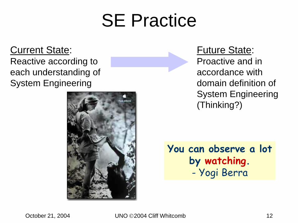
SE PracticeCurrent State:Reactive according to each understanding of System Engineering
Future State:Proactive and in accordance with domain definition of System Engineering (Thinking?)
You can observe a lot by watching.- Yogi Berra
UNO 2004 Cliff WhitcombOctober 21, 2004 13
What’s the Problem? • System Engineering used to be the domain of
the Chief Engineer• More complex systems, more outsourcing,
increasing computer based control, increase the need for system engineers
• System Engineering is a combination of art & science
• Even in business domains that encourage SE, there is a cyclic nature to the emphasis
• Domain knowledge is essential– Hiring System Engineers from other companies is
not immediately cost effective Source: Ginny Lentz, Otis Elevator
UNO 2004 Cliff WhitcombOctober 21, 2004 14
EIA 632 Systems Engineering Model
AcquisitionProcess
SupplyProcess
Acquisition& Supply
Technical Evaluation
SystemsAnalysisProcess
SystemVerification
Process
RequirementsValidationProcess
End ProductsValidationProcess
Technical Management
PlanningProcess
AssessmentProcess
ControlProcess
SystemDesign
RequirementsDefinition Process
Solution DefinitionProcess
ProductRealization
ImplementationProcess
Transition to UseProcess
Plans,Directives& Status
Outcomes&
Feedback
Requirements
Designs
Products
AcquisitionRequest
SystemProducts
EIA 632INCOSE Handbook
UNO 2004 Cliff WhitcombOctober 21, 2004 15
Why Develop an Architecture?• Typically, an architecture is developed because key
people have concerns that need to be addressed by the systems within an organization
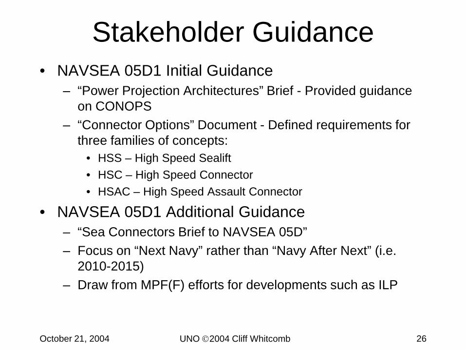
• Such people are commonly referred to as the “stakeholders” in the system
• The role of the architect is to address these concerns– Identifying and refining the requirements that the stakeholders
have– Developing views of the architecture that show how the
concerns and the requirements are going to be addressed– Showing the trade-offs that are going to be made in reconciling
the potentially conflicting concerns of different stakeholders
Without an architecture, it is highly unlikely that all the stakeholder concerns and
requirements will be considered and met.
UNO 2004 Cliff WhitcombOctober 21, 2004 16
Architecture Definition• The arrangement of
elements and subsystems and the allocation of functions to them to meet system requirements. (INCOSE)
• The arrangement of the functional elements into physical blocks. (Ulrich & Eppinger)
• The embodiment of concept, and the allocation of physical/informational function to elements of form and definition of structural interfaces among the elements. (Prof. Crawley, MIT)
• The arrangement of function and feature that maximizes some objective. (Jack Ring)
UNO 2004 Cliff WhitcombOctober 21, 2004 17
Architecture Aspects• The arrangement of
elements and subsystems and the allocation of functions to them to meet systemrequirements. (INCOSE)
• The arrangement of functionand feature that maximizes someobjective. (Jack Ring)
• The embodiment of concept, and the allocation of physical/informational functionto elements of form and definition of structural interfacesamong the elements. (Ed Crawley, MIT)
• The arrangement of thefunctional elements into physical blocks. (Ulrich & Eppinger)
The interconnection and arrangement of function and feature that maximizes some
objective.
UNO 2004 Cliff WhitcombOctober 21, 2004 18
System Architecture Considerations• Harmonize Definition with that of Established
Architects• Architecture is Concerned with
– Relationships and patterns of relationships (e.g. Frank Lloyd Wright, M. Pei)
– System design pattern of “context, content, structure”– Practices of Model-Based Systems Engineering
• Architect– Function and feature are givens– Primarily concerned with arrangement of these
“The better architecture is the one that yields the best fit (or score) with respect to the purpose for which the system is to be created. ” Jack Ring, Discovering the Architecture of Product X,
INCOSE International Symposium 2001
UNO 2004 Cliff WhitcombOctober 21, 2004 19
The Architect• Proposes and develops
options– Applies creativity in the
development of concepts– Considers new
technology
• Thinks holistically considering product life cycle
• Resolves ambiguity• Communicates ideas to
others
UNO 2004 Cliff WhitcombOctober 21, 2004 20
Underlying Architecting Objectives
• Be synthetic first, analytic second
• Think holistically - with a global perspective
• Use creative and critical thinking
• Learn from best practices in System Architecting Good artists copy.
Great artists steal.Pablo Picasso
UNO 2004 Cliff WhitcombOctober 21, 2004 21
Architecting Scope• No Universally Applicable Stopping Point
• Architecting Continues Beyond Concept
Conceptual development complete when design is sufficiently refined (in enough views) for the
client to make a decision to proceed.
Shepard the conceptual design through detailed design, oversee creation, and advise client on
certification.
UNO 2004 Cliff WhitcombOctober 21, 2004 22
Design Progression• Progressive Refinement
– Basic pattern of engineering– Organizes progressive transition in
processes• From Ill-structured, chaotic, heuristic• To rigorous engineering implementation• From mental concept• To physical manifestation
UNO 2004 Cliff WhitcombOctober 21, 2004 23
Design Concepts for System Architecture
• Architecting– Predominantly eclectic mix of rational and heuristic
processes– Normative rules and group processes enter in lesser roles
• Process Revolves Around Models– Composed of scoping, aggregation, decomposition
(partitioning), integration, certification– Few rational guidelines exist for these processes
• Uncertainty– Inherent in complex systems design– Use tools and heuristics to reduce uncertainty
• Continuous Progression– Organizing principle of architecting, models, and supporting
activities
UNO 2004 Cliff WhitcombOctober 21, 2004 24
Fusion of Art and Science
If you want to know how a building will fare in a hurricane, ask a civil engineer. If you want a building to express your desires, and do so beyond rote calculations
of floor space and room types, ask an architect.
MIT Stata CenterMIT Building 20
UNO 2004 Cliff WhitcombOctober 21, 2004 25
Sea Connector System Architecture
• Connector concepts vital to Seabasing and Seapower 21.• SEA 05D1 exploring design alternatives for SEA00 using a
systematic approach; result is a framework and set of concepts that characterize the design space.
• SEA 05D1 tasked CSC/JJMA/G&C to conduct concept studies.
• Study being performed in three phases:– Initial studies to conduct initial ASSET based concept studies for
each of three families– Second Phase to refine the ASSET studies, apply additional
analysis tools, explore cargo handling and other issues in greater detail
• Personnel 14376*• MCBul 3501 14403*• * does not include NSE
Enclosure (4) to MPF(F) Action Memo Number 3 (CME D0007584.A1)
UNO 2004 Cliff WhitcombOctober 21, 2004 29
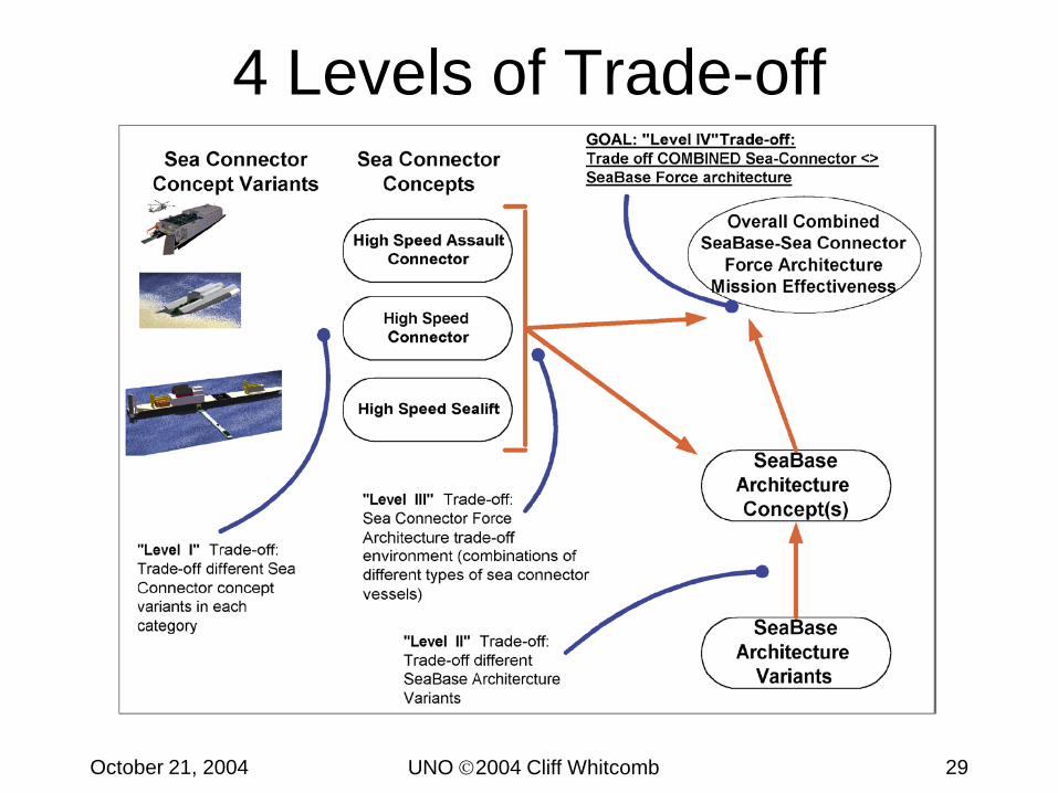
4 Levels of Trade-off
UNO 2004 Cliff WhitcombOctober 21, 2004 30
Levels of Trade-off• Trade-off between different concepts within each ship
class: HSS, HSC, HSAC– Need to define generic MOEs for each class of vessels
• To include ‘binary’ MOEs (beachable / non-beachable)– Develop Response Surface for each class of vessels– Include MOEs as additional variables/“columns” in RS matrix
• Trade-off between different combinations of vessels (force architecture)– Model using EXTEND– EXTEND OMOEs
• Time (days / hours) to achieve objectives• Combat Power Index (over time period)
– Each ‘class’ of Sea Connector will be represented as a generic “ship” entity in EXTEND (with associated MOPs/MOEs)
UNO 2004 Cliff WhitcombOctober 21, 2004 31
Establish 4 ‘Nodes’• Depending on which scenario, path may ‘skip’ node• Scenarios:
• Ships/equipment ‘queued’ in EXTEND by “orders” • Logic paths at each node to account for transfer
modes/times
CONUS ADVANCE BASE SEA BASE OBJECTIVE
UNO 2004 Cliff WhitcombOctober 21, 2004 32
Generic 4-Node Model
NODE A:CONUS
NODE B:ADVANCE BASE
NODE C:SEA BASE
NODE D:OBJECTIVE
6000 nm 2000 nm 200 nm
1 MEB in 10 DAYS 1 BLT in 1 PoD
UNO 2004 Cliff WhitcombOctober 21, 2004 33
Scenario 1: MPF(F)-Centered Model
NODE A:CONUS
NODE B:ADVANCE BASE
NODE C:SEA BASE
NODE D:OBJECTIVE
6000 nm 2000 nm 200 nm
HSS
Strategic Sealift
ISSUES ARISING:
-- We will likely need to model MPF(F) and “Strategic Sealift” in EXTEND for this scenario-- Need to decide how to ‘split’ MEB load between MPF(F) [B C] and HSS [A C]-- HSC is HCFNB variant-- HSAC is MCMB variant-- NOTE: RANGE FROM AC == 8,000 NM
-- We will likely need to model “Sealift” ships (?existing vessels) and LPH, LKD classes in EXTEND for this scenario-- Need to decide how to ‘split’ MEB load between Sealift [A B], LPH [AC], LKD [BC] and HSS [A C]-- HSC is HCFNB variant-- HSAC is FWDB variant: RANGE IS ONLY 150 NM-- NOTE: RANGE FROM AC == 8,000 NM
-- We will likely need to model “Sealift” ships (?existing vessels) and CLF class in EXTEND for this scenario-- Need to decide how to ‘split’ MEB load between Sealift [A B] and HSS [A C]-- HSC is HCMB or HCFB variant, I.e. both “beachable” variants (required for this scenario)-- HSAC is MCMB or MCSB variant-- NOTE: RANGE FROM AC == 8,000 NM (FOR HSS)
-- We will likely need to model “Sealift” ships (?existing vessels) and HSASS class in EXTEND for this scenario-- Need to decide how to ‘split’ MEB load between Sealift [A B] and HSASS [A C]-- HSC is FNB, HCMB or HCFB variant-- HSAC is MCMB or MCSB variant-- **NB** NO HSS VARIANTS IN THIS SCENARIO
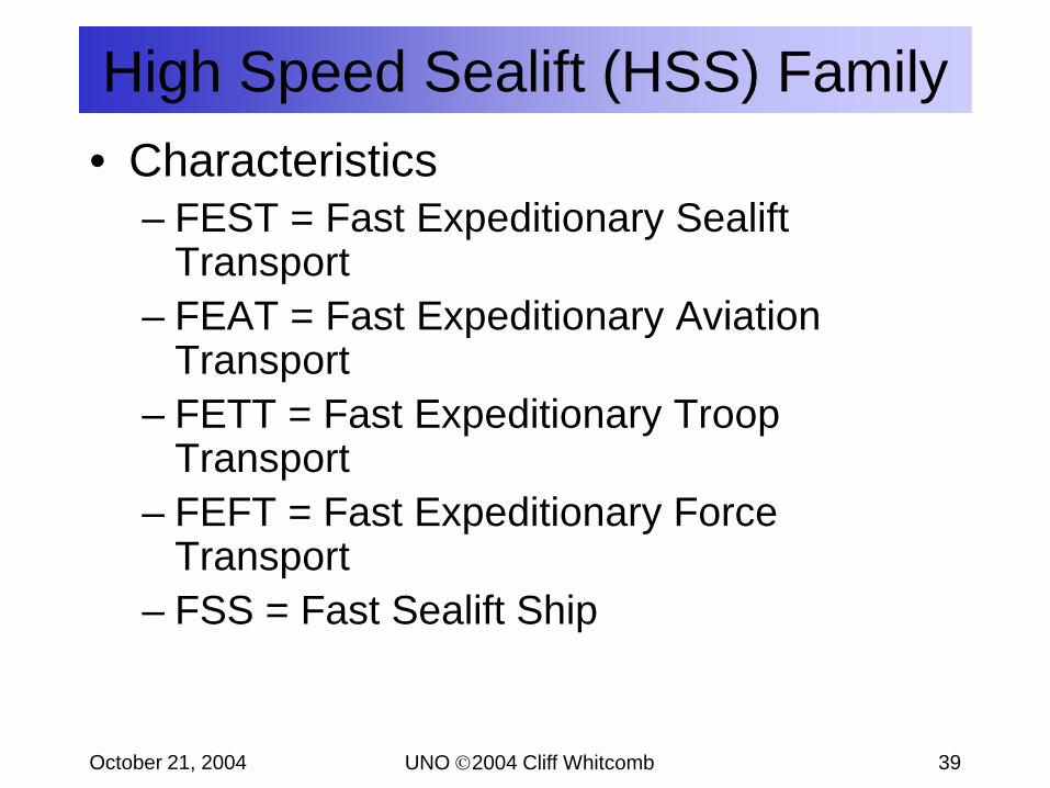
• Characteristics– FEST = Fast Expeditionary Sealift
Transport– FEAT = Fast Expeditionary Aviation
Transport– FETT = Fast Expeditionary Troop
Transport– FEFT = Fast Expeditionary Force
Transport– FSS = Fast Sealift Ship
High Speed Sealift (HSS) Family
UNO 2004 Cliff WhitcombOctober 21, 2004 40
Family MembersAll 6000-naut mile range -- loaded
FEST/FEFT Monohull
FETT/FSS Monohull
FEAT Monohull
High Speed Sealift (HSS) Family
Name Speed Vehicle Cargo Troop
FEST 40 kt 9290 m2 90 TEU 1150FEFT 40 kt 12,080 m2 100 TEU 1100FEAT 40 kt (aircraft only) 250 TEU 1625FETT 40 kt 2320 m2 50 TEU 3300FSS 30 kt 17,650 m2 230 TEU 2000
LOA: 294 m BMAX: 32 m Disp FL: 52,155 / 56,898 mtonLWL: 280 m BWL: 32 m Four ScrewsDraft FL: 11.0 / 11.0 m 8 x LM6000PANAMAX Dimensions 298,280 kW 38 kt
LOA: 294 m BMAX: 32 m Disp FL: 58,766 / 64,208 mtonLWL: 280 m BWL: 32 m Four / Two Screws Draft FL: 11.0 / 10.7 m 8 x LM6000 / 4 x LM6000 PANAMAX Dimensions 298,280 kW 38/30 kt
Particulars:LOA: 300 m BMAX: 40 m Disp FL: 66.590 mtonLWL: 285 m BWL: 40 m Four ScrewsDraft FL: 11.0 m 8 x LM6000Post PANAMAX Dimensions 298,280 kW 36 kt
UNO 2004 Cliff WhitcombOctober 21, 2004 41
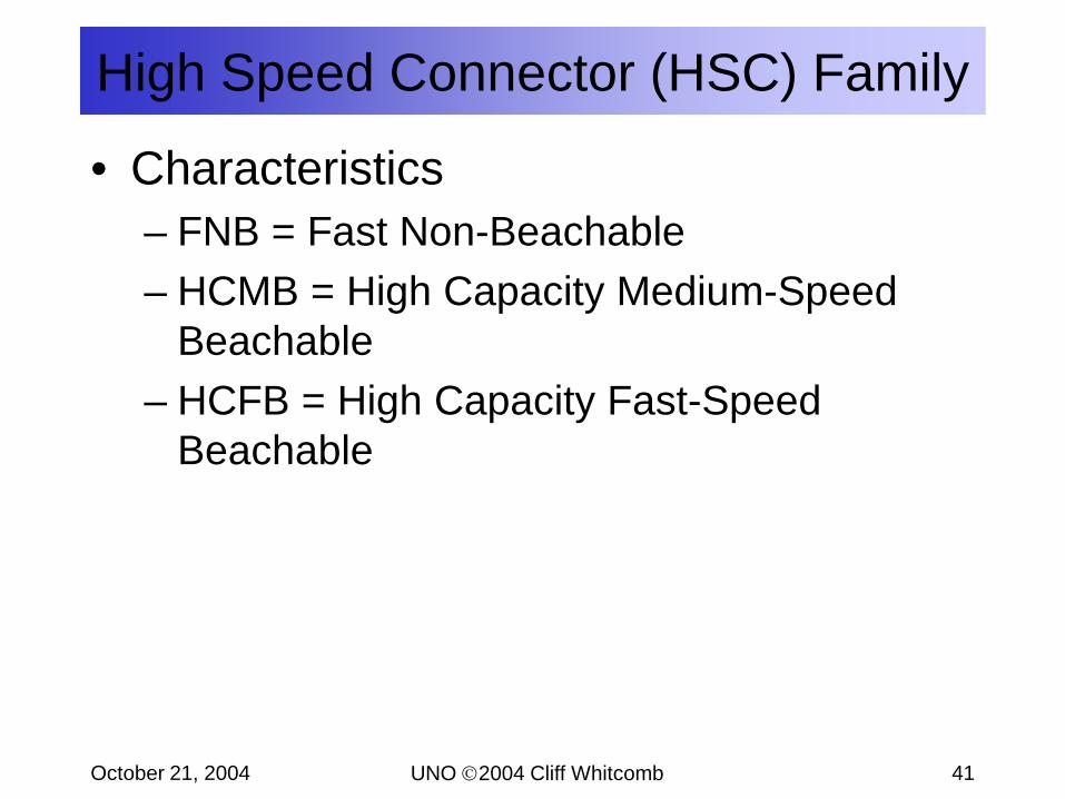
• Characteristics– FNB = Fast Non-Beachable– HCMB = High Capacity Medium-Speed
Beachable– HCFB = High Capacity Fast-Speed
Beachable
High Speed Connector (HSC) Family
UNO 2004 Cliff WhitcombOctober 21, 2004 42
High Speed Connector (HSC) FamilyFamily Members
All 2000-nautical mile range
Name Speed Vehicle Troop AccomStow
Fast NonBeach 40 kt 3250 m2 125 + 375 AirlineHi Cap Med Beach 25 kt 4180 m2 405Hi Cap Fast Beach 45 kt 4180 m2 105 + 300 Airline
Fast Non-Beachable (Slender Mono)
Hi Cap Medium Beachable (Mono)
Hi Cap Fast Beachable(Slender Monohull and Catamaran Alternatives)
LOA: 200.4 m BMAX: 22.2 m Disp FL: 11825 tonneLWL: 191.0 m BWL: 22.2 m Quad ScrewDraft: 4.9 m FL Depth: 15.4 m 4 x Med Speed Diesel
31000 kW 26.8 ktsustained at 80% MCR
LOA: 235 mLWL: 215 mBMAX: 32.2 mDraft: 6.9 m FL
5.0 m Arrival(with Cushion-Assist)
Displacement FL: 20292 tonne6 Waterjets -- 6 x LM6000 Gas Turbines 223700 kW 43 kt @ 90% MCR
LOA: 215.4 m BMAX: 22.6 m Disp FL: 15527 tonneLWL: 205.1 m BWL: 22.6 m Quad WaterjetsDraft: 5.1 m FL Depth: 16.3 m 4 x LM6000 GT
4.8 m Arrival 149100 kW 40.2 ktsustained at 90% MCR
LOA: 262.7 mLWL: 249.8 mBMAX: 24.0 mDraft: 5.5 m FL
5.2 m ArrivalDisplacement FL: 21231 tonne4 Waterjets -- 8 x LM2500+ Gas Turbines 208800 kW 43.2 kt @ 90% MCR
UNO 2004 Cliff WhitcombOctober 21, 2004 43
• Characteristics– MCMB = Medium Capacity, Medium
Range, Beachable– FWDB = Fast, Well-Deck Capable,
Beachable– MCSB = Medium Capacity, Short Range,
Beachable
High Speed Assault Connector (HSAC) Family
UNO 2004 Cliff WhitcombOctober 21, 2004 44
High Speed Assault Craft (HSAC) FamilyFamily Members
(All Beachable)
Name
MCMBMCSBFWDB
MCSB
MCMB
FWDB
Speed(kts)
302045
FerryRange(nm)
40004000NA
MissionRange(nm)
10001000150
MissionArea(m2)
11151115372
Missionload(mt)
300300145
Conventional MonohullSurface Effect Ship
LOA: 95.6 m BMAX: 23 m LWL: 88.6 m BWL: 23 mDispl: 1637 m tonsDraft (off cushion): 2.9 mDraft (on cushion): 1.5 m
Hybrid Catamaran / Surface Effect Ship (SES)
LOA: 60 m BMAX: 14.6 m LWL: 54 m BWL: 14.0 mDispl: 472 m tonsDraft (off cushion): 2.0 mDraft (on cushion): 0.9 m
LOA: 126 m BMAX: 13 m LWL: 122 m BWL: 13 mDispl: 2473 m tonsDraft FL: 2.3 m
Troops
110110125
UNO 2004 Cliff WhitcombOctober 21, 2004 45
Connector Study Conclusions• Ships in the three families are feasible in the 2010 timeframe.• The HSS Family has the highest confidence level relative to the HSC
and HSAC Families.• HSS: FEST, FEFT, FETT, and FEAT are feasible but rely on LM6000
propulsion plant and four shaft configuration that is unproven at this time; FSS is feasible but requires only twin screw due to reduced speed requirement.
• HSS Family interface issues are high priority; resolving satisfactory at-sea cargo transfer is critical to success.
• HSC: HCMB is feasible and has least risk of HSC alternatives. FNB requires powerplant development. HCFB is high risk and only marginally feasible and potentially too large for austere ports.
• HSAC: MCSB is feasible using proven technologies. Both MCMB and FWDB require development of skirt technology and ramp systems. Shallow draft and beaching requirements for high performance small craft are challenging.
UNO 2004 Cliff WhitcombOctober 21, 2004 46
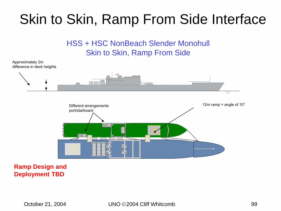
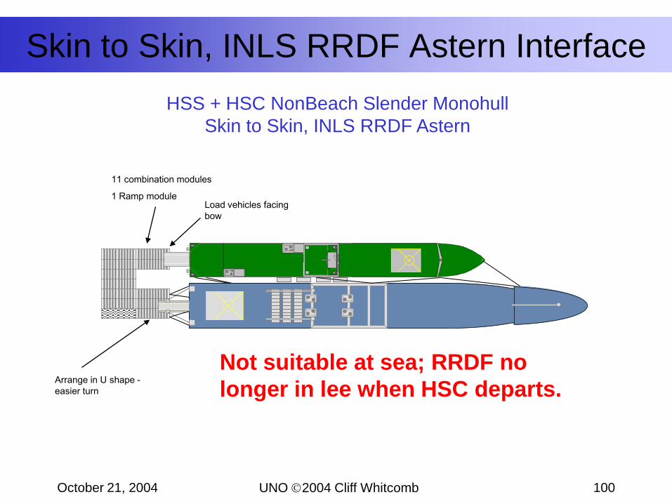
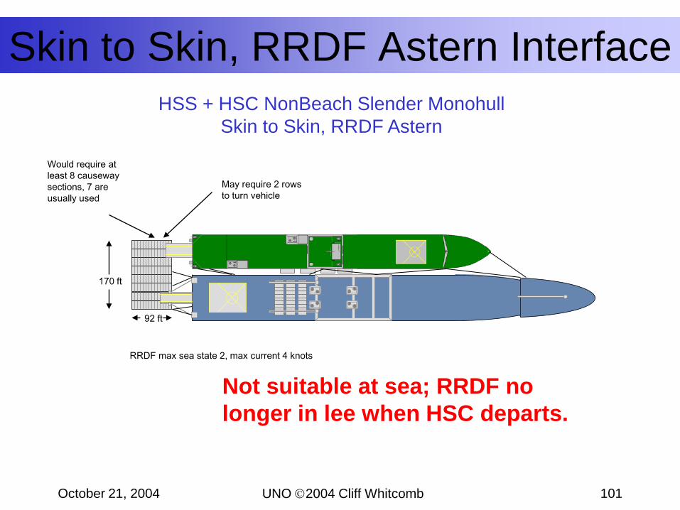
Interface ConsiderationsCargo transfer at-sea will be a major challenge.
UNO 2004 Cliff WhitcombOctober 21, 2004 47
Interface Issues
Ship or Craft Interfacing with HSS
Type of InterfaceMechanism
HSC HSAC MPF(F)
Shipboard Cranes for Cargo Transfer
X X X
Ramps, Crane Deployed
X NA Potential
Ramps, Self-Deploying
X NA Potential
RRDF or equal X X XILP NA X NAX indicates that interfaces have been investigated to minimal level.
Interfaces Considered
UNO 2004 Cliff WhitcombOctober 21, 2004 48
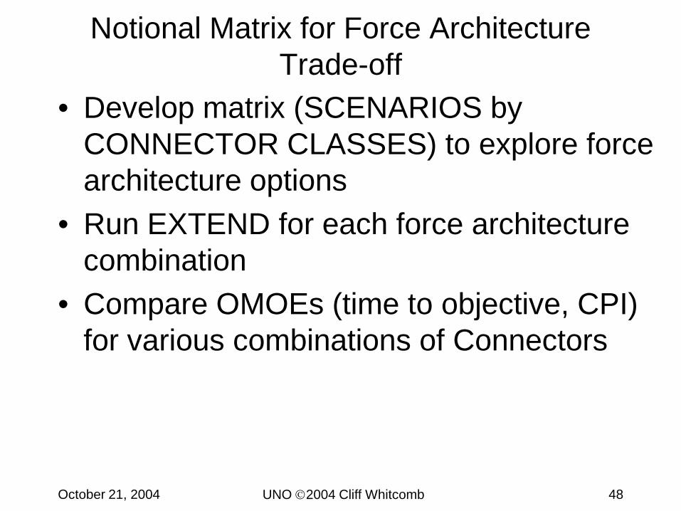
Notional Matrix for Force Architecture Trade-off
• Develop matrix (SCENARIOS by CONNECTOR CLASSES) to explore force architecture options
• Run EXTEND for each force architecture combination
• Compare OMOEs (time to objective, CPI) for various combinations of Connectors
UNO 2004 Cliff WhitcombOctober 21, 2004 49
Notional Matrix for Force Architecture Trade-off
MPF(F)-Centered
RFP CONUS-Based WPP
options 1.1 1.2 2.1 2.2 3.1 3.2 4.1 4.2HSS
HSC
HSAC
Other AssetsTime to ObjectiveCombat Power Index
TASK IS TO IDENTIFY COMBINATIONS OF VESSELS TO PERFORM REQUIRED MISSION
UNDER EACH SCENARIO – COULD POTENTIALLY HAVE TWO OR MORE ‘OPTIONS’ OR
COMBINATIONS UNDER EACH SCENARIO
UNO 2004 Cliff WhitcombOctober 21, 2004 50
How to ‘Evaluate’ (?) this Mix of Platforms / Sub-systems and Missions?
UNO 2004 Cliff WhitcombOctober 21, 2004 51
Some Initial ‘Composite’ Metrics for Sea Connectors
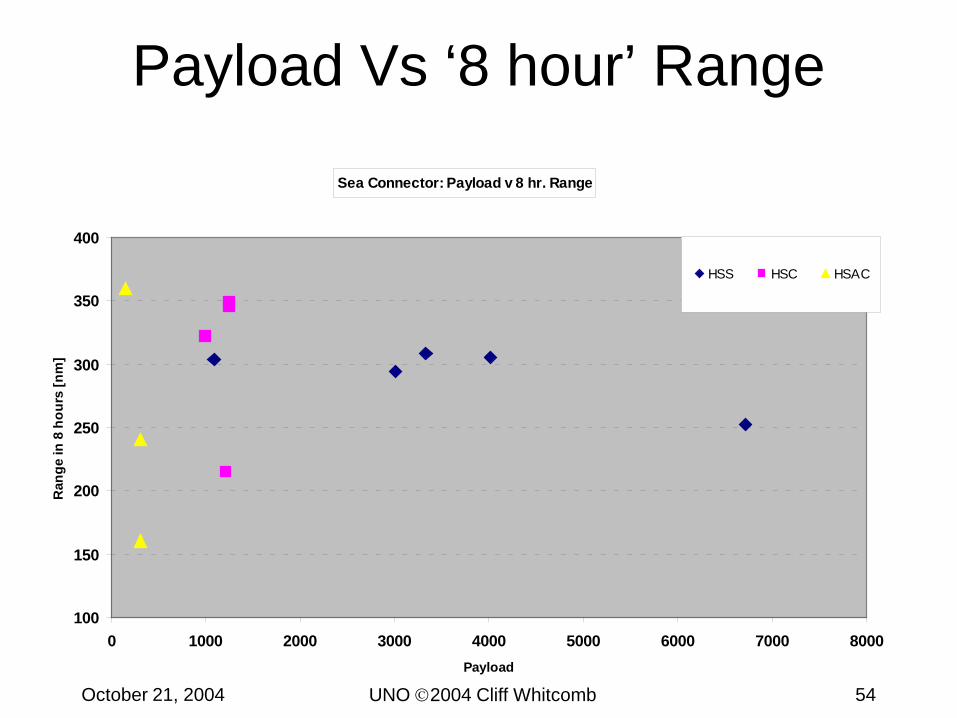
• Transport Factor and Other Metrics for Sea Connectors– Speed vs Transport Factor– Speed vs Payload Transport Factor– Payload vs ‘8 hour’ Range– Number of Sea Connectors required to
transport 1 surface BLT• Using following limiting criteria
– Number of persons– Vehicle area– Vehicle weight
UNO 2004 Cliff WhitcombOctober 21, 2004 52
Speed Vs Transport Factor
Speed V Transport Factor for Sea Connector Variants
0
10
20
30
40
50
60
70
80
20 25 30 35 40 45 50Sustained Speed [knots]
Tran
spor
t Fac
tor,
TF
HSS HSC HSAC
UNO 2004 Cliff WhitcombOctober 21, 2004 53
Speed Vs Payload TF
Speed V Payload Transport Factor for Sea Connector Variants
0
1
2
3
4
5
6
7
8
20 25 30 35 40 45 50Sustained Speed [knots]
Payl
oad
Tran
spor
t Fac
tor,
TFp
HSS HSC HSAC
UNO 2004 Cliff WhitcombOctober 21, 2004 54
Payload Vs ‘8 hour’ Range
Sea Connector: Payload v 8 hr. Range
100
150
200
250
300
350
400
0 1000 2000 3000 4000 5000 6000 7000 8000Payload
Ran
ge in
8 h
ours
[nm
]
HSS HSC HSAC
UNO 2004 Cliff WhitcombOctober 21, 2004 55
Sea Connectors Required to Transport 1 BLT
0
2
4
6
8
10
12
14
16
Num
ber o
f shi
ps
TROOPS VEHICLE AREA VEHICLE WT
Limiting criteria: troop numbers / vehicle area / vehicle weight
Number of Sea Connectors required to transport 1 Surface BLT (from MEB 2015)FEST
FEFT
FETT
FSS
FEAT
FNB
HCMB
HCFB-SM
HCFB-C
MCMB
MCSB
FWDB
For the HSAC vessels, the number of personnel/troops to be transported is the primary limiting factor
UNO 2004 Cliff WhitcombOctober 21, 2004 56
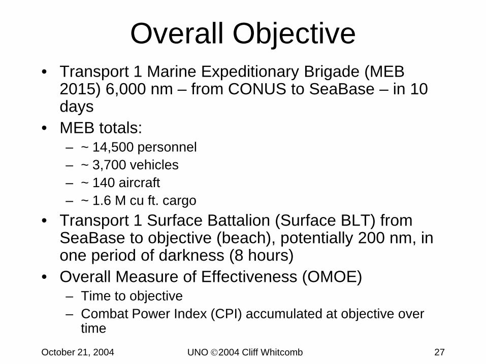
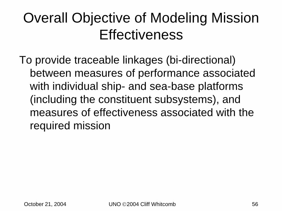
Overall Objective of Modeling Mission Effectiveness
To provide traceable linkages (bi-directional) between measures of performance associated with individual ship- and sea-base platforms (including the constituent subsystems), and measures of effectiveness associated with the required mission
UNO 2004 Cliff WhitcombOctober 21, 2004 57
Mission Effectiveness• OMOE = Overall Measure of Effectiveness• MOE = Measure of Effectiveness
• A measure of the effectiveness of the system in performing a particular mission
• MOP = Measure of Performance• Physics- and design-based attributes of platform AND
Factors (for each class of ship):LBP, B, T, Installed Power etc.
Factors for Overall RS:-5 factors for each class:Payload-wt; Payload-area; Payload-troops; Speed; Cost-3 classes: HSS, HSC, HSAC== 15 factors.
Speed (HSS)
Speed (HSC)
Speed (HSAC)
‘slider’ control
CPI
Use upper and lower bounds of responses for each parameter (speed etc.), and JMP, to generate variants for EXTEND executor
UNO 2004 Cliff WhitcombOctober 21, 2004 60
System-based Trade Environment• System Level
– Complexity• Emergent properties can become
more critical than subsystem performance properties
• Only need 80% solution for Concept Design Level
• Trade Environment– Use meta-models for trade-off
studies– Shared space among
stakeholders• Design• Decision Making
• “Shared Space” can mitigate– Ambiguity– Uncertainty– Exclusion of innovative solutions
Pareto Boundary
Feasible Region(white area)
Infeasible Region(shaded area)
Presenter
Presentation Notes
Example System Level Trade: Mechanical drive is the naval architect's (marine engineer's) solution - Electric drive is the system level solution. Cannot make conclusions on these perspectives without the operational scenario. Need to trade-off based on system level needs as effectiveness in the projected end use environment. With regard to the top level process involved in a new system design, a set of steps should be followed. First, a solution neutral set of functions to be accomplished should be defined. Second, a series of concepts should be designed to map function to form, with the form being the final product developed. Since the application of creativity is exerted upon the concepts, these must be the focus of the trade-off – not the functions or the forms.
UNO 2004 Cliff WhitcombOctober 21, 2004 61
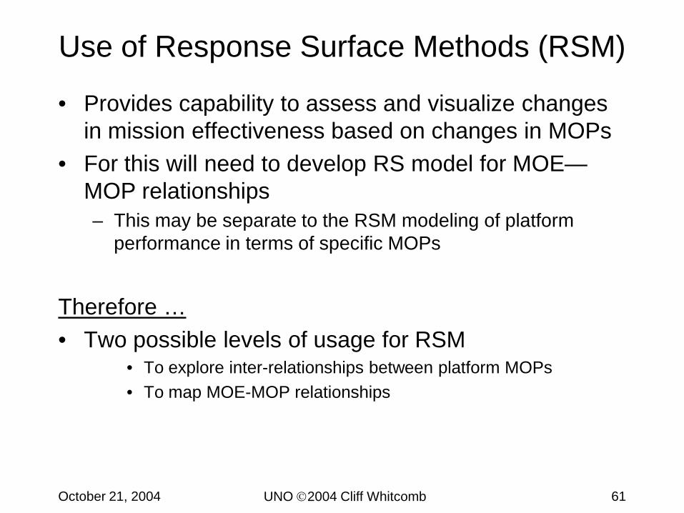
Use of Response Surface Methods (RSM)
• Provides capability to assess and visualize changes in mission effectiveness based on changes in MOPs
• For this will need to develop RS model for MOE—MOP relationships – This may be separate to the RSM modeling of platform
performance in terms of specific MOPs
Therefore …• Two possible levels of usage for RSM
• To explore inter-relationships between platform MOPs• To map MOE-MOP relationships
UNO 2004 Cliff WhitcombOctober 21, 2004 62
Response Surface Designs• 3 Level Design Analysis
Creates Mathematical Model– Empirically based– From experimental data
• Response Function– Interpolated function predicts
response between factor points tested in experiment
– Visualized as a “surface”• Typical Designs
– Box-Behnken– Central Composite Design (CCD)
• Also known as Box-Wilson design
Response: Vertical Acceleration
Example shown is from: Optimal Deadrise Hull Analysis and Design Space Study of Naval Special Warfare High Speed Planing Boats, LT Todd E. Whalen, USN, MIT Masters Thesis, 2002
UNO 2004 Cliff WhitcombOctober 21, 2004 63
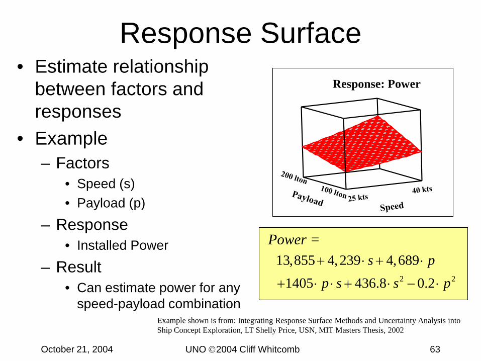
Response Surface
2 2
13,855 4,239 4,6891405 436.8 0.2
s pp s s p+ ⋅ + ⋅
+ ⋅ ⋅ + ⋅ − ⋅
Power =
Response: Power• Estimate relationship
between factors and responses
• Example – Factors
• Speed (s)• Payload (p)
– Response• Installed Power
– Result• Can estimate power for any
speed-payload combinationExample shown is from: Integrating Response Surface Methods and Uncertainty Analysis into Ship Concept Exploration, LT Shelly Price, USN, MIT Masters Thesis, 2002
UNO 2004 Cliff WhitcombOctober 21, 2004 64
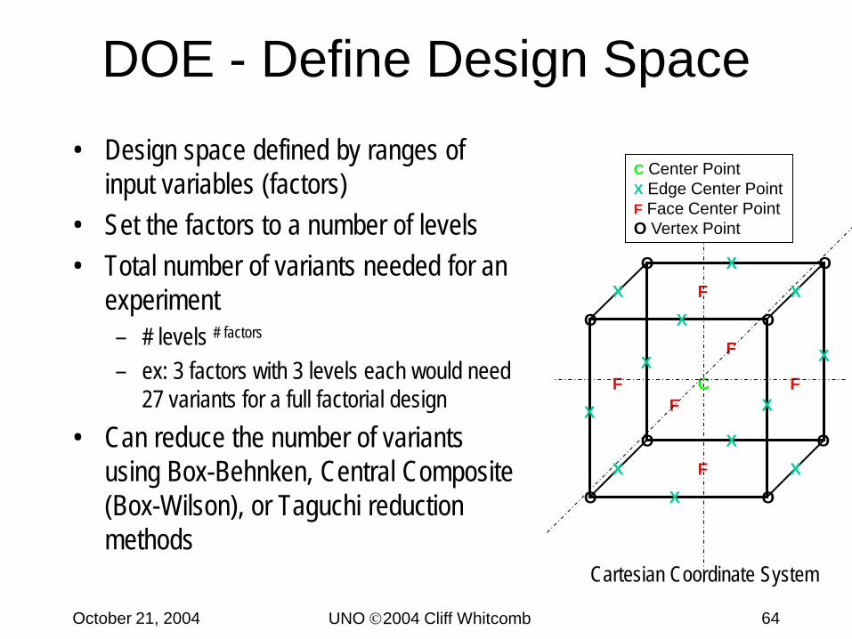
DOE - Define Design Space
X
XX
X
XX
XX
X X
XX
O
O
O O
O
O
O
O
C
F
F
F
F
F
F
• Design space defined by ranges of input variables (factors)
• Set the factors to a number of levels• Total number of variants needed for an
experiment– # levels # factors
– ex: 3 factors with 3 levels each would need 27 variants for a full factorial design
• Can reduce the number of variants using Box-Behnken, Central Composite (Box-Wilson), or Taguchi reduction methods
C Center PointX Edge Center PointF Face Center PointO Vertex Point
Cartesian Coordinate System
UNO 2004 Cliff WhitcombOctober 21, 2004 65
Curve Fit Points from Design Space
ε++++= ∑∑∑∑= +===
k
i
k
ijjiij
k
iiii
k
iii xxbxbxbby
1 11
2
10
Create Response Surface Equations
Interpolated Curve Fit Creates Response Surface
Presenter
Presentation Notes
The following terminology is used in RSM: · Factors: The input variables or design parameters. Represented by capital letters (A, B, C) or xi. · Levels: The different settings for each factor. For a two-level factor, the low level is represented by (-1) and the high level as (+1). For a three level factor, the intermediate level is represented by (0). · Response: The output of interest, represented by the letter y. · Interaction(s): Refer to dependencies between a factor’s effect on the response and levels of another factor. The interaction of A and B is represented as AB.
UNO 2004 Cliff WhitcombOctober 21, 2004 66
Investigate Response Surfaces Using JMP
Pareto Boundary
Feasible Region(white area)
Infeasible Region(shaded area)
UNO 2004 Cliff WhitcombOctober 21, 2004 67
• Submarine Design Study Tasking– Redesign Virginia class submarine– Allow for insertable payload modules for rapid reconfigurability
• ISO standard size (20 ft x 20 ft)• Up to 3 modules
Analyze DOE Case Study Improved Payload Submarine
Warfighting Capability
Mission Tasks
Mission Profiles
Task Attributes
Overall Measure of Effectiveness (OMOE)
Measure of Effectiveness (MOE)
Measure of Performance (MOP)Key Performance Parameters (KPP)
Get Modular, Get Payload, Get Connected
UNO 2004 Cliff WhitcombOctober 21, 2004 68
• Create a “Modular and Affordable” submarine• What payload could be carried?• What is the impact on Depth and Speed?
Analyze DOE Case Study Overview
UNO 2004 Cliff WhitcombOctober 21, 2004 69
• Submarine Joint Strategic Concepts for the 21st
Century
Analyze DOE Case Study Modular Payloads
UNO 2004 Cliff WhitcombOctober 21, 2004 70
Analyze DOE Case Study Electromagnetic Rail Gun
• EM Gun Performance Plot
0
20
40
60
80
100
120
140
0 50 100 150 200 250 300 350 400 450
Range (km)
Altit
ude
(km
)
5 kg10 kg 20 kg40 kg60 kgTroposphere30 kg
51+/-1 degrees
Velocity = 2.5 km/s
no drag above this altitude
47 MJ Impact Energy
~15 sec ~30 sec
5-7 min
UNO 2004 Cliff WhitcombOctober 21, 2004 71
• Submarine Gun Module
Analyze DOE Case Study Electromagnetic Rail Gun Module
UNO 2004 Cliff WhitcombOctober 21, 2004 72
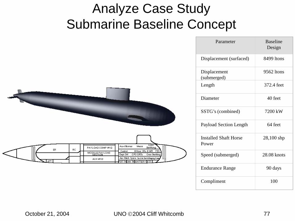
Design Summary
ER RC
FTTATTAUX #1/2
MODULE PAYLOADSECTION
PAYLOAD COMP #1/2
BATTERYSAN TKPOT TK
Aux/Stores Mess CrewBerthing
Control Officer SRs & WRFESDept Off CPO QRTs Crew BerthingAux Mach SpaceSp Unit Berth/Staging Area
• Need– Submarine Payload Capacity Improvement
• Allowable Compromise– Top Speed, Maximum Diving Depth
• Constraint– USS Virginia hull form
Add Modular Payload Section
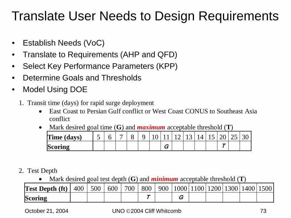
UNO 2004 Cliff WhitcombOctober 21, 2004 73
1. Transit time (days) for rapid surge deployment• East Coast to Persian Gulf conflict or West Coast CONUS to Southeast Asia
conflict• Mark desired goal time (G) and maximum acceptable threshold (T)
• Establish Needs (VoC)• Translate to Requirements (AHP and QFD)• Select Key Performance Parameters (KPP)• Determine Goals and Thresholds• Model Using DOE
UNO 2004 Cliff WhitcombOctober 21, 2004 74
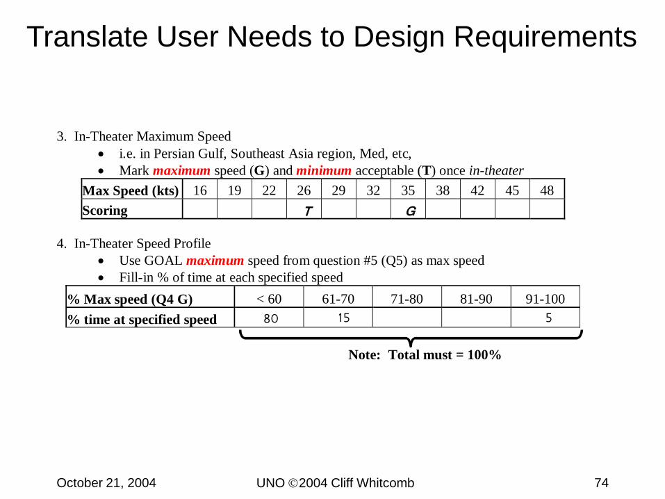
3. In-Theater Maximum Speed• i.e. in Persian Gulf, Southeast Asia region, Med, etc,• Mark maximum speed (G) and minimum acceptable (T) once in-theater
• C I P D Naval Construction and Engineering ProgramMIT 13A
UNO 2004 Cliff WhitcombOctober 21, 2004 80
Pr edi ct i on Pr of i l e
2837
1669
2150. 478
0. 57735
0. 12184
0. 366324
1
0
0. 451968
Di amet er ( f t )
38
Test Dept h ( f t )
850
Speed ( kt s)
28
Payl oad Sect i on ( f t )
65. 5
Desi r abi l i t y
Case Study: Cost Constrained Optimality
2.5 B$ Cost Limit
UNO 2004 Cliff WhitcombOctober 21, 2004 81
Case Study: Pareto PlotSolution Comparison
OMOE vs Cost
2.25 B$ Limit
No Cost Limit2.50 B$ Limit
2.0 B$ Limit
0.0
0.1
0.2
0.3
0.4
0.5
0.6
0.7
0.8
0.9
1,0001,5002,0002,5003,0003,5004,000
Average Follow-on Ship Cost (M$)
OM
OE
Random 88 ft Payload, Variable Speed 65 ft Payload, Variable Speed "Optimal" Designs
Random Variant Generation
Frontier variants always have minimum depth and diameter
UNO 2004 Cliff WhitcombOctober 21, 2004 82
Case Study: Pareto PlotSolution Comparison
OMOE vs Cost
2.25 B$ Limit
No Cost Limit2.50 B$ Limit
2.0 B$ Limit
0.0
0.1
0.2
0.3
0.4
0.5
0.6
0.7
0.8
0.9
1,0001,5002,0002,5003,0003,5004,000
Average Follow-on Ship Cost (M$)
OM
OE
Random 88 ft Payload, Variable Speed 65 ft Payload, Variable Speed "Optimal" Designs
Selected Variant
UNO 2004 Cliff WhitcombOctober 21, 2004 83
Seaconnector Project Issues• Identified MOPs and MOEs for each class of
Connector • Defined ‘generic’ ships in EXTEND• How to link between RS models and EXTEND RS?• How to ‘fit’ surface BLT (priority loading) components
with known available payload weights/areas for Connectors?
• Determine how best to track Combat Power Index (CPI) in EXTEND
• How to include survivability / sustainability / beaching capability, etc ???
UNO 2004 Cliff WhitcombOctober 21, 2004 84
Additional Detailed Information
UNO 2004 Cliff WhitcombOctober 21, 2004 85
HSS Family Conclusions• FEST, FEFT are feasible pending development of
high power CPP and marinized version of LM6000.• FETT is feasible under similar conditions but may be
a better design at greater than PANAMAX beam for stability.
• FSS is feasible under similar conditions but may be a better design at greater than PANAMAX beam for stability. Ten thousand tons of fixed ballast required at 32 m beam.
• FEAT is feasible, although it doesn’t quite achieve 37 knot speed under conditions above.
• All but FEAT subject to satisfactory development of multiple interface issues.
UNO 2004 Cliff WhitcombOctober 21, 2004 86
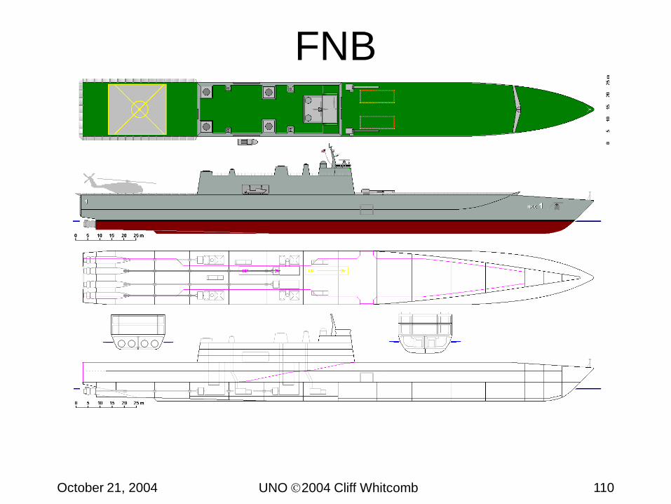
HSC Family Conclusions• FNB is feasible but has moderate development risks.
– Requires development in areas of powerplant (turbines and waterjets).– Risk area is design for acceptable hull structural responses.
• HCMB is minimal risk concept.– HCMB is basically a conventional design, despite need for triple or quad-
screw plant; several alternative propulsion options are attractive.– ”Economical” (in context of military Sea Basing) at 25 knots threshold
speed.– 30-knot speed objective can be met with LM2500 gas turbines , either with
electric drive and propellers, or with waterjets. • HCFB is potentially feasible, but presents high development and
operational risks in several areas.– Monohull and multihull variants both near 45 knots (but not quite: best so far
43.2 kt at 90%)– Catamaran draft is too high (without cushion-assist).– Monohull variants likely to be considered “too big for Port Austere”.
UNO 2004 Cliff WhitcombOctober 21, 2004 87
HSAC ConclusionsMCMB• Feasible with some design development required
– Propulsion plant within current technologies– Auxiliary systems (except for bow ramp) non-developmental– Aluminum construction already heavily used in commercial sector– Bow ramp will be developmental but not outside current
technologies– Retractable cushion skirts will require design development
investmentMCSB• Feasible and readily within current technology
– Propulsion plant within current technologies– Auxiliary systems non-developmental– Aluminum construction already heavily used in commercial sector
UNO 2004 Cliff WhitcombOctober 21, 2004 88
HSAC ConclusionsFWDB• Feasible with design development required
– Propulsion plant within current technologies– Auxiliary systems (except for bow ramp) non-developmental– Shallow draft and high speed benefit from composite construction.
Not a proven technology for US Navy Craft.– Complex structural design required to reduce wave slamming while
keeping overall depth small enough to interface with well deck.– Seakeeping expected to be acceptable, but requires further
analysis to model interaction with well deck.– Bow ramp will be developmental but not outside current
technologies– Retractable cushion skirts will require design development
investment– Folding navigation and communication antenna will be
developmental, but there are already applications of this capability in the US Navy.
UNO 2004 Cliff WhitcombOctober 21, 2004 89
HSS Family Recommendations• Begin seakeeping studies to establish structural loads and
added resistance in a seaway and motion limits to set sustained speed definition.
• Longitudinal strength and scantling calculations should be performed to confirm there is enough ship at baseline forward to give required strength with producible thickness of steel.
• Begin looking at fatigue considerations – since these ships will not be in constant service may be able to design to relaxed standards.
• Should bring propeller manufacturers into program to determine ability to design and build controllable pitch propellers at this power level.
• Initiate tradeoffs to determine optimum proportions and form coefficients for speed-power considerations.
UNO 2004 Cliff WhitcombOctober 21, 2004 90
HSC Family Recommendations• Refine the definition of “Port Austere”
– Draft– Length and “handiness”constraints
• Consider appropriate survivability requirements for HSC Family – Self-defense– Susceptibility (especially MIW)– Vulnerability and recovery (Are 15% length of hit and CPS worth it?)
• Initiate propulsion system development for FNB– LM6000 turbines and compatibly rated waterjets
• Initiate hull form and structural trades for FNB – Wave-piercing bow variant– “Exotic” content in hull structural materials
• Begin development of a bow ramp system design for HCMB – Would also be applicable to a beachable (new) variant of FNB
• Begin machinery trades for HCMB– Integrated electric (diesel or turbine)
UNO 2004 Cliff WhitcombOctober 21, 2004 91
HSAC RecommendationsMCMB• Investigate retractable skirt cushions• Mature lightship weight estimate• Conduct preliminary seakeeping assessment• Investigate and develop at-sea cargo transfer operations• Develop conceptual design for folding bow ramp
MCSB• Develop conceptual design for folding bow ramp• Develop conceptual general arrangements and machinery


![MySQL Installation Steps · MysQL server 5.5.24 connector,'0DBC 5.1.10 Connector/C++ 1.1.0 Connector/C 6.0.2 Connector'] 5.1.19 connector,'NET 6.4.4 MySQL Documentation 5.5.24 Samples](https://static.documents.pub/doc/80x56/5fdb66d66432103e17178378/mysql-installation-steps-mysql-server-5524-connector0dbc-5110-connectorc.jpg)


