1. Open/Close Doors. 2. Prop Pitch 3. Throttle 4. Adjust Time (non functional) 5. Altimeter Calibration Knob 6. Removes Pilots Side Yoke 7. Removes Passenger Side Yoke 8. Mixture 9. Carb Air Heat 10. Magneto Key (R and L mag position not simulated) 11. Main Battery 12. Master Switch 13. Fuel Pumps (1 fuel pump MUST be on for engine to operate. 2 nd pump is backup) 14. Start 15. Running Lights 16. Instrument Lights 17. Dome Light 18. Anchor Light (White Light on tail, for when moored in water) 19. Parking Brake 20. Radio Tuning Knob 21. Radio Volume Knob 22. Radio Tuning Knob KC Flight Shop Republic Seabee Page 1
Transcript
1. Open/Close Doors. 2. Prop Pitch 3. Throttle 4. Adjust Time (non functional) 5. Altimeter Calibration Knob 6. Removes Pilots Side Yoke 7. Removes Passenger Side Yoke 8. Mixture 9. Carb Air Heat 10. Magneto Key (R and L mag position not simulated) 11. Main Battery
12. Master Switch 13. Fuel Pumps (1 fuel pump MUST be on for engine to operate. 2nd pump is backup) 14. Start 15. Running Lights 16. Instrument Lights 17. Dome Light 18. Anchor Light (White Light on tail, for when moored in water) 19. Parking Brake 20. Radio Tuning Knob 21. Radio Volume Knob 22. Radio Tuning Knob
KC Flight Shop Republic Seabee Page 1
1. Seat (Move forward and back. Move forward slightly to remove pilot or passanger)
2. Flap lever (Up, Neutral, Down)
3. Wheels Lever (Up, Down)
4. Manual hydraulic pump
KC Flight Shop Republic Seabee Page 2
1. Prop reverse lever (typically covered by guard)
2. Prop reverse lever guard (Opens only when your at idle, and prop is set to fine)
3. Elevator Trim
Flight Sim specific instructions.
When parked in water, shut down the engine and engage the parking brake to deploy anchor rope and enjoy the sound of water lapping on the hull. When on land, shut down the engine and engage the parking brake to deploy tie down ropes and tire chocks. These are just graphical enhancements and will not actually anchor down the aircraft.
If you want to take a screenshot without pilot or passenger’s, move the seat slightly forward.
To use the reverse prop pitch, you must be at idle, and at the lowest prop pitch to disengage the prop reverse guard. Right click on the prop reverse lever to activate. Your aircraft will slowly back up until the prop reverse is disengaged.
Please visit our forums at www.kcflightshop.com/forum/ if you have any feature suggestions, find any bugs, or simply want to chat with the KCFS crew!
The following pages is a direct copy of the 1947 pilots manual of the Republic Seabee and does not reflect all the features of the simulated KCFS Seabee. Its only used for historical and entertainment value.
KC Flight Shop Republic Seabee Page 3
1
KC Flight Shop Republic Seabee Page 4
Kevin
Cross-Out
2
PERFORMANCE & SPECIFICATIONS.........6GENERAL......................................................8OPERATING YOUR SEABEE .......................10
SYSTEMS......................................................21ENGINE..................................................21FUEL SYSTEM.......................................22ENGINE CONTROLS.............................24SURFACE CONTROLS..........................26LANDING GEAR.....................................28HYDRAULIC SYSTEM ...........................30BRAKES AND WHEELS ........................32
KC Flight Shop Republic Seabee Page 5
3
CARE AND MAINTENANCE .........................34ACCESS.................................................34HANDLING, JACKING, ANCHORING....35LUBRICATION DIAGRAM......................36SERVICING DIAGRAM ..........................38SERVICING THE SHOCK STRUT .........40REMOVAL OF WHEEL AXLE ................41TIE-DOWN AND MOORING ..................42CONTROL SETTINGS ...........................43UPHOLSTERY .......................................44EXTERIOR SURFACES.........................44PLEXIGLASS .........................................44WHEELS ................................................46BRAKES .................................................46BRAKE ADJUSTMENT ..........................47TAIL WHEEL UPSTOP...........................47LANDING GEAR SIGNAL SWITCHES...48CYLINDER ADJUSTMENT ....................48FUEL FLOW SHUT OFF ........................49VALVE ADJUSTMENTS.........................49CARBURETOR ......................................50ENGINE..................................................51
POWER PLANTModel.............................................................Franklin “500”Rated horsepower.......................................................... 215
KC Flight Shop Republic Seabee Page 10
8
ENGINE CONTROLS.The engine controls, which consist of throttle, mixture and carburetor heat
are push-pull type, designed so that all knobs are forward against the panel fortake-off. When the knobs are pulled out, the selections are: closed throttle,mixture in the idle cut-off and carburetor heat “Hot”. When pushed in, selectionsare open throttle, carburetor heat “Cold” and mixture auto-rich. The intermediatepositions of the mixture control select lean mixtures.
PROPELLER CONTROL.The standard propeller installation is ground adjustable and non-
controllable. The optional installation is controllable by push-pull control on theinstrument panel. To select high RPM, push the control against the panel; toselect low RPM, pull the control aft. The controllable propeller is also reversible.To reverse propeller: Idle the engine, place normal pitch control in high RPM, andslide the reversing lever control, which is located overhead, to the full aft position.
Note: Do not exceed 1750 RPM in reverse!When returning propeller to normal thrust, be certain that the propeller reversinglever is locked in the forward position so that accidental propeller reversal isimpossible.
SURFACE CONTROLS.Control of surfaces is by conventional wheel-and-post and rudder pedals.
To remove the dual control wheel release the locking clip and pull the pin betweenthe wheels. Remove the dual column from its socket and stow in the bracketprovided under the right front seat. Replace the pin and secure it with the lockingclip. A conventional trim tab lever and indicator is located overhead.
LANDING GEAR.To lower or retract the landing gear, lift the gear selector handle and slide it
to the desired position; move the pump handle fore and aft with full strokes untilthe gear reaches the locked position at which time the signal lights will indicatelock. As an added precaution, pump several extra strokes.
KC Flight Shop Republic Seabee Page 11
9
LANDING FLAPS.To lower or raise the flaps, lift the flap selector handle and place it in the
forward or aft position and pump. Partial flap deflection may be had by returningthe selector to neutral after pumping flaps to desired position.
PARKING.To set the parking brake, push the pedals and pull the control knob marked
“Park”. To release the parking brake, return the parking control and depresspedals.
SIGNALS.When the gear signal light is green, the landing gear is locked down; if the
signal light is red, the landing gear is up. These signals are automatic.
MISCELLANEOUS.To adjust the front seats for leg-room, release the lock at the base of the
seat and slide the seat to the desired position. The back rests of the front seatsmay be reclined to form a double bed.
All lights are controlled from switches on the instrument panel.The anchor is stowed under the floor in the forward section of the cabin.
The baggage compartment access door is above the rear seat.
A single fuel pressure gage provides readings for both fuel pumps. Toselect the desired reading, switch pump selector on the instrument panel to“RIGHT” or “LEFT”.
KC Flight Shop Republic Seabee Page 12
10
As safety precautions for you as pilot and for your passengers acomplete inspection of your Seabee should be made before each flight.Don’t neglect the weather forecasts. Weather conditions play one of themost important parts in successful flight. Check all instructional materialfor procedures and follow them.
Don’t start inspection until ignitionswitch is checked for off position.
KC Flight Shop Republic Seabee Page 13
11
EXTERIOR CHECK (PREFLIGHT)
Look your airplane over carefully; walk around it and observe thelanding gear, floats, water rudder and attachments for looseness or wear.
Examine the structure for cracks and for corrosion particularly if youare operating on salt water.
Check oil level and view lines and connections for leaks.Be on the lookout for proper safetying of bolts, nuts and
turnbuckles.Move control surfaces and note their alignment and soundness.Make certain the doors, access openings, inspection plates and
cowlings are properly fastened.Inspect your fueling. Make absolutely certain that the gas cap is
properly replaced and firmly secured on the filler neck.Survey the propeller for nicks, cuts and cracks.Drain water at strainer and tank sump drains and check that drain
cocks are closed.
KC Flight Shop Republic Seabee Page 14
12
INTERIOR CHECK (PREFLIGHT)As soon as you enter the cabin require your passengers to fasten
their safety belts; then fasten yours. Cultivate this habit.Carefully view the cabin and note that all doors are securely closed
and that your fire extinguisher and first aid kit are at hand.Check your surface controls again from the inside---raise and lower
the elevators...work the ailerons and rudder...move the engine controls.Check propeller reversing lever for normal thrust setting and insure
that the lock is engaged so that the propeller may not be reversedaccidentally.
With your ignition switch still in the “OFF” position, turn on thebattery switch. Observe your lights and instruments.
Consult the weight book for permissible loading and check that youare within the load limits; then set trim in proper relation.
STARTING ENGINEAs a precautionary measure before starting engine always make
certain that no one is near the propeller. If the engine has not beenoperated for some time and is cold, it is a good policy to pull the propellerthrough by hand for about two revolutions before starting.
To start the engine, open throttle slightly beyond the idle position.Push mixture control in to the full rich position and carburetor heat controlto the cold position. Close battery switch and place ignition switch to“START” position. When engine fires return ignition switch to “B” (both)position.
Do not operate starter for more than 30 seconds at any one time;allow one minute rest before engaging the starter again.
If the engine appears to be loaded (flooded), place mixture in theidle-cut-off position (full out), open throttle wide and crank the engine overwith the starter to clean out the mixture before attempting to start in theregular manner.
KC Flight Shop Republic Seabee Page 15
13
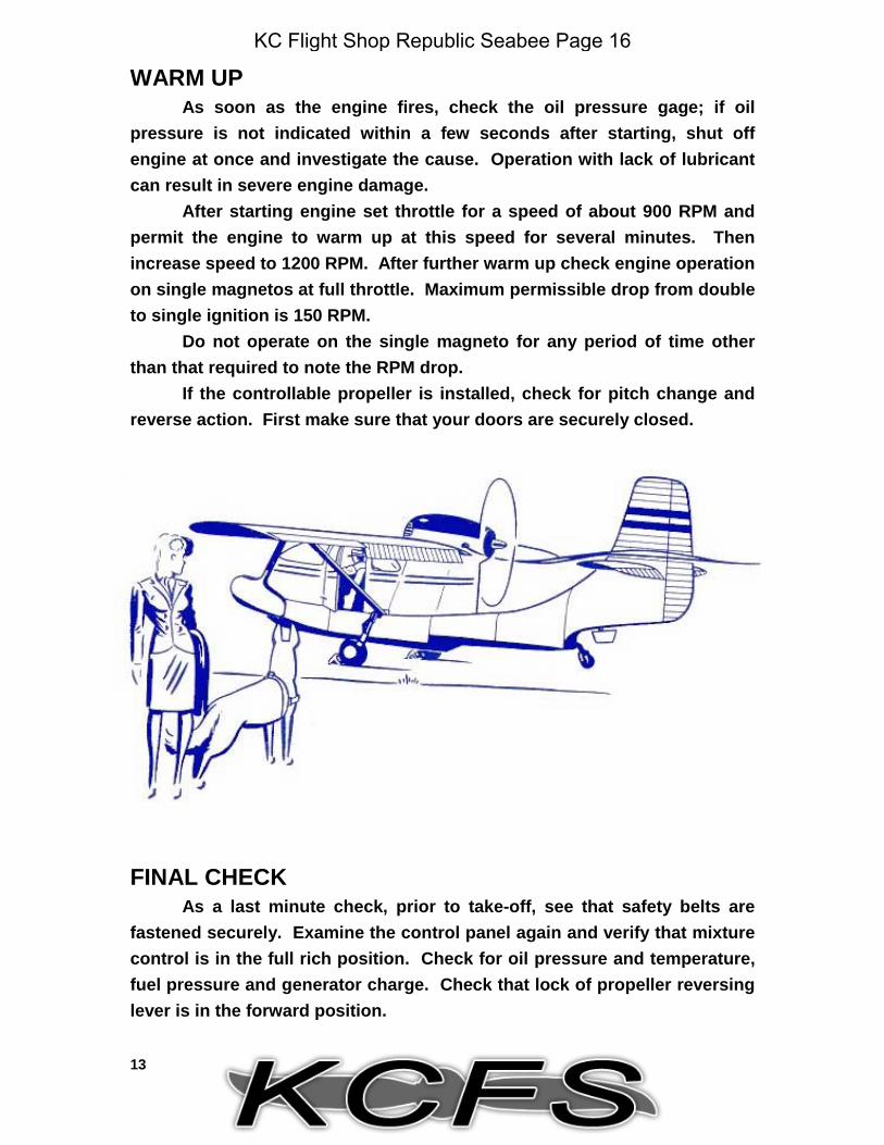
WARM UPAs soon as the engine fires, check the oil pressure gage; if oil
pressure is not indicated within a few seconds after starting, shut offengine at once and investigate the cause. Operation with lack of lubricantcan result in severe engine damage.
After starting engine set throttle for a speed of about 900 RPM andpermit the engine to warm up at this speed for several minutes. Thenincrease speed to 1200 RPM. After further warm up check engine operationon single magnetos at full throttle. Maximum permissible drop from doubleto single ignition is 150 RPM.
Do not operate on the single magneto for any period of time otherthan that required to note the RPM drop.
If the controllable propeller is installed, check for pitch change andreverse action. First make sure that your doors are securely closed.
FINAL CHECKAs a last minute check, prior to take-off, see that safety belts are
fastened securely. Examine the control panel again and verify that mixturecontrol is in the full rich position. Check for oil pressure and temperature,fuel pressure and generator charge. Check that lock of propeller reversinglever is in the forward position.
KC Flight Shop Republic Seabee Page 16
14
LAND TAKE-OFFAfter the ground test has been completed the Seabee is ready for
take-off:Taxi airplane forward in order to lock and center tailwheel.Open throttle to full RPM.The airplane will take off in about 800 feet with a normal load; when
airborne, retract the landing gear.Adjust throttle to power desired (see power charts).
WATER TAKE-OFFTake-off from water presents little difference from normal land take-
off except that on water the Seabee requires about 1000 feet of run at sealevel, with full gross load and no wind. Extreme care should be exercisedon glassy water take-offs. Be sure to continue the climb after leaving thewater to prevent the possibility of letting the nose drop and flying backonto the water.
Use fully-extended flaps for water take-offs. When airborne, retractthe flaps at a slow, steady rate.
CAUTIONDo not retract flaps at less than 250feet altitude for airspeeds below 80
mph.
KC Flight Shop Republic Seabee Page 17
15
CRUISE CONTROLFor increased economy in level flight the mixture may be leaned
provided that allowable cylinder head temperatures are not exceeded. Tolean, maintain constant throttle position in level flight and observe RPMindicator while adjusting mixture control; mixture setting is at best powerwhen RPM is maximum. A change in altitude or throttle setting willnecessitate readjustment of the mixture control. Maintain correlated rpm-manifold pressure settings for controllable propeller installations.
CLIMBINGAt sea level the Seabee climbs at a rate of 650 feet per minute. The
best climb occurs at 75 IAS and at 2500 RPM with flaps and gear up.
STALLINGStalling speed at sea level is 58 IAS with flaps and wheels down and
66 IAS when landing gear and flaps are up. Ample warning of approach tothe stall is evidenced by a noticeable buffeting of the control column.When the stall occurs, the Seabee pitches moderately with little tendencyto roll, then regains flying speed. A spin will not occur unless assisted byuncoordinated control movements. Should the airplane go into a spin,recovery is accomplished by neutralizing the controls. Recovery may behastened by using normal recovery technique; namely, rudder against thespin followed by a slight forward movement of the control column. A burstof power greatly accelerates recovery.
KC Flight Shop Republic Seabee Page 18
16
DIVINGCAUTION
Do not exceed 159 mph in dives
APPROACHBefore approaches for landings, place mixture in the “full-in”
position (rich) and propeller control to high RPM position. See that allsafety belts are fastened and check the fuel quantity. If necessary, set thecarburetor to “HOT”.
With the throttle set at 1000 RPM, maintain an approach speed of80 IAS. This speed is best for dead stick landings.
LANDINGSCAUTION
Before landing check that the mixtureselection is full-rich and that propeller
control is in high-RPM.
For a land plane landing set the selector valve for flaps and gear to
KC Flight Shop Republic Seabee Page 19
17
the forward position and pump until the signal light glows green signifyingthat the wheels are down and locked. When close to the runway cut thethrottle; with moderate use of the brakes the landing roll will be about 400feet. After completion of the landing roll raise the flaps and taxi to positiondesired, then set the parking brake.
Normal landing of the Seabee on water involves the same landingtechnique except that the gear remains up (signal light red) and flaps aredown. The airplane hydroplanes on its vee bottom and directional andlateral control is maintained as long as there is forward speed. The waterrudder operates in conjunction with the air rudder.
When landing the Seabee on glassy or still water, make no attempt tojudge height; use night landing technique. Adjust power to maintain 65 IASwith flaps down. This combination will insure a nose-high attitude andgradual rate of descent. Allow the airplane to land itself using a slightamount of back pressure on the control wheel. When the water iscontacted, close the throttle and proceed as normal.
STOPPING ENGINEPermit the engine to run at approximately 800 RPM for a short time
before stopping it.To stop engine pull mixture control lever full out to the idle-cut-off
position.After the engines stops, shut off the ignition switch and then the
master and battery switches.
KC Flight Shop Republic Seabee Page 20
18
EMERGENCY OPERATION
Too dark to make a safe wheel landing? Forced landing in a shortfield? It may never be necessary, but should you be in a tight spot, leaveyour wheels up or retract them if already down and come in for a keellanding. Flight testing proves that an emergency keel landing in theSeabee is apparently a safe landing. The Seabee has been keel-landed onhard surface runways, on sand beaches, and on turf.
If, on an approach, you find it necessary to undershoot a field due torunning out of gas or engine failure or for other reasons, and have not timeto fully retract the landing gear, move the landing gear selector handleback to “landing gear up” position and start pumping. The first couple ofstrokes will unlock the gear and move it sufficiently aft to permit it to swingon landing. The extent of damage in this event will be slight and mostimportant of all there is negligible danger of personal injury. Remember, inany emergency, a keel landing is the best way out.
The Seabee has been demonstrated to be fully maneuverable underall flight conditions with one flap down and the other up. Test stalls andrecoveries in this condition experienced no change from normalcharacteristics. Therefore in the event that one flap only should deflect orif one flap fails to retract, excess aileron is available for use against theextended flap and the Seabee can be flown with relative ease.
Negligence in failing to check doors closed before flight, can be theonly reason for a bow door swinging open during a negative-airload-creating maneuver; in this condition the Seabee is easily maneuverableand controllable for a perfectly safe landing. Some buffeting will occur dueto the interrupted air flow, but it is best to avoid any possibility of thisexperience by checking your doors closed before take-off.
During water operation with one float only, hold that float on the waterkeeping the other wing out of the water. Effective aileron control can easilybe maintained at 40 mph or over. If speed is less, the airplane may be heldin its normal attitude by keeping the wing with the missing float headedinto the wind so that the airplane will lean over onto the other wing. If thewing without the float has dropped into the water, it may be lifted out of the
KC Flight Shop Republic Seabee Page 21
19
water by stepping out throwing your weight on the wing lift strut of theopposite wing. You can then taxi to shore. Any water in the wet wing willdrain off in a few moments.
Don’t forget that Seabee seat backs and cushions are designed tosupport a person afloat and may be used as life preservers in anemergency.
Fuel-flow may be completely cut-off, if necessary, by pulling forwardon the fuel flow shut-off control, which is located under the pilot’s seat.
Your best assurance against emergencies, is faithful inspection, careand proper maintenance.
KC Flight Shop Republic Seabee Page 22
KC Flight Shop Republic Seabee Page 23
21
ENGINEThe Seabee is equipped with a Franklin “500” engine which is a six
cylinder, 500 cu. in. displacement, direct drive, horizontally opposedengine.
The engine is mounted to rigid structure by three shock mounts, twoat the front and one at the rear.
Detailed specifications are:
Rated HP 215Rated Speed 2500 RPMIdle Speed 500 to 600 RPMFuel-Min Octane 80 Nonleaded AviationCompression Ratio 7.0:1Displacement 500 cu. in.Bore 5 cu. in.Stroke 4.25Fuel Pump Dual AC Diaphragm TypeCarburetor Marvel MA4-5Ignition Dual Eismann Magneto
Model LA-6Magneto Point Clearance .019”-.021”Ignition Timing 32°° Adv. Left and RightFiring Order 1-4-5-2-3-6Oil Capacity 13 quartsOil Temp (Max) 230° FOil Press (Max) 50 psiSpark Plugs Auto Lite AH4ASpark Plug Gap .014” to .018”Valve clearance .040”
(with lifters bled down)Starter 12 voltGenerator 12 volt, 35 Amps
KC Flight Shop Republic Seabee Page 24
22
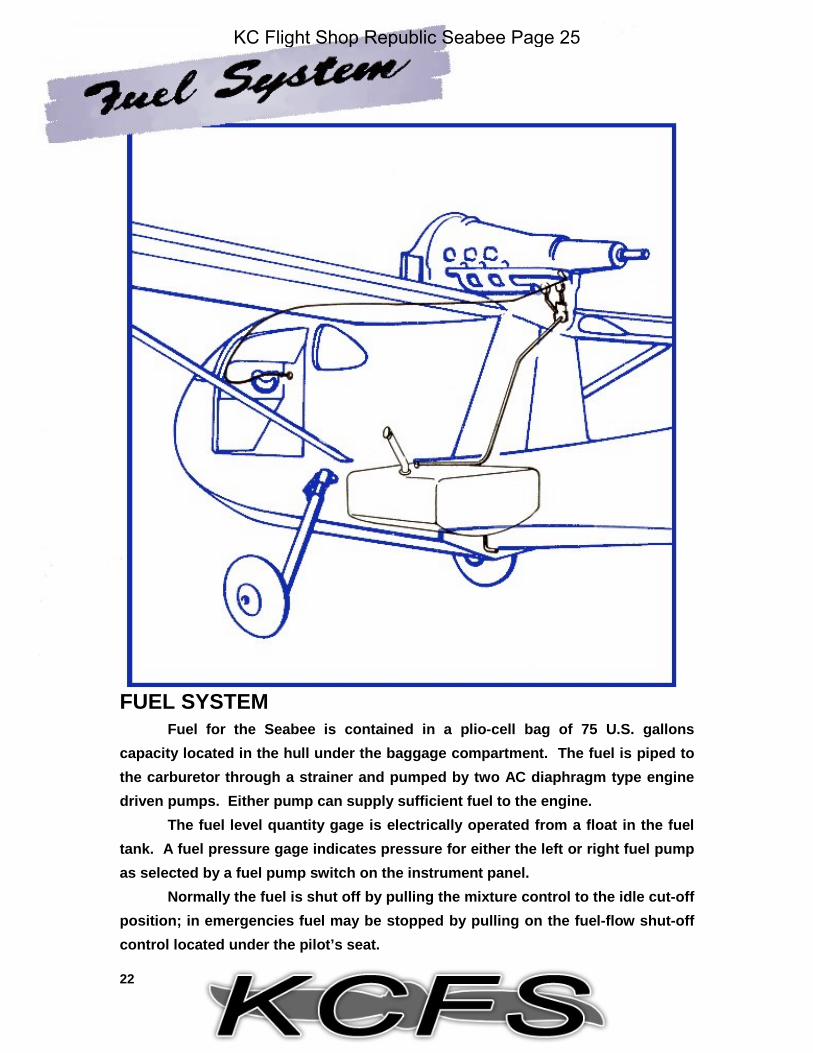
FUEL SYSTEMFuel for the Seabee is contained in a plio-cell bag of 75 U.S. gallons
capacity located in the hull under the baggage compartment. The fuel is piped tothe carburetor through a strainer and pumped by two AC diaphragm type enginedriven pumps. Either pump can supply sufficient fuel to the engine.
The fuel level quantity gage is electrically operated from a float in the fueltank. A fuel pressure gage indicates pressure for either the left or right fuel pumpas selected by a fuel pump switch on the instrument panel.
Normally the fuel is shut off by pulling the mixture control to the idle cut-offposition; in emergencies fuel may be stopped by pulling on the fuel-flow shut-offcontrol located under the pilot’s seat.
KC Flight Shop Republic Seabee Page 25
23
FUEL SYSTEM DIAGRAM
KC Flight Shop Republic Seabee Page 26
24
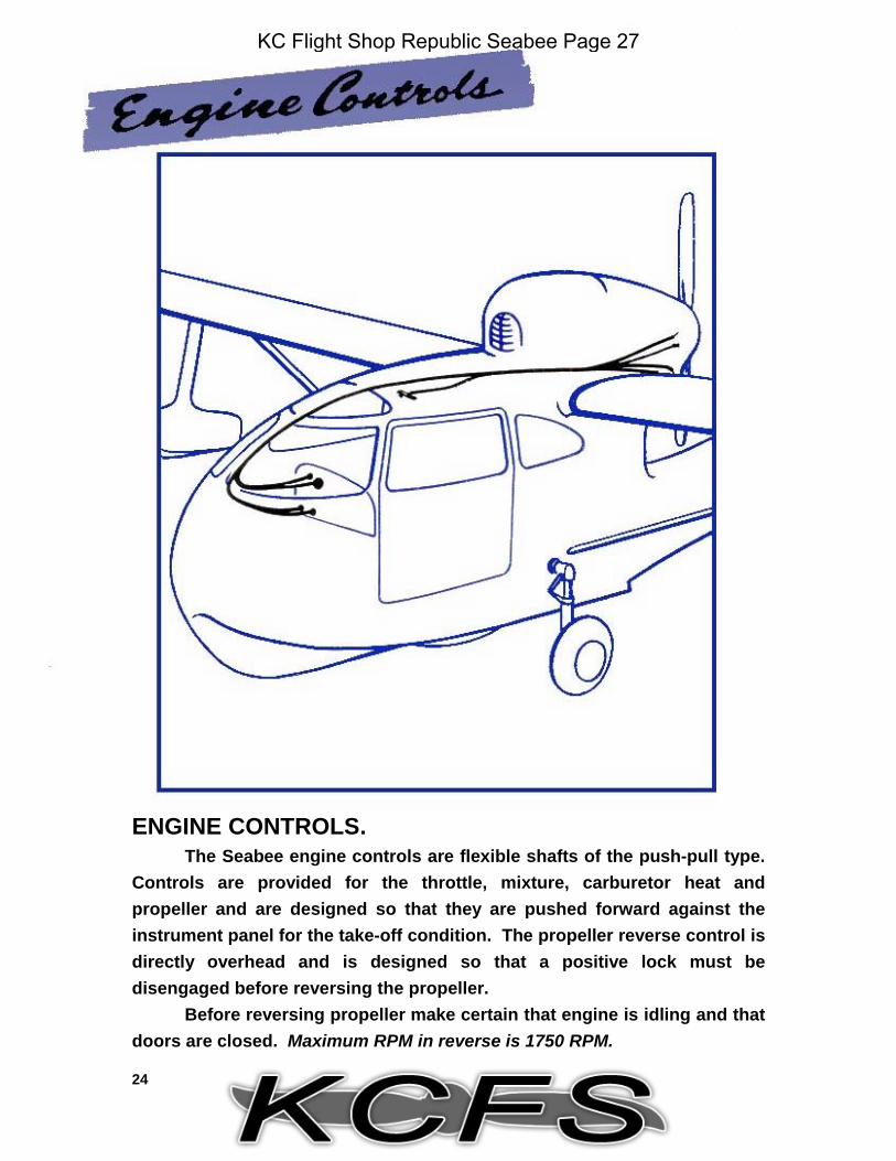
ENGINE CONTROLS.The Seabee engine controls are flexible shafts of the push-pull type.
Controls are provided for the throttle, mixture, carburetor heat andpropeller and are designed so that they are pushed forward against theinstrument panel for the take-off condition. The propeller reverse control isdirectly overhead and is designed so that a positive lock must bedisengaged before reversing the propeller.
Before reversing propeller make certain that engine is idling and thatdoors are closed. Maximum RPM in reverse is 1750 RPM.
KC Flight Shop Republic Seabee Page 27
25
ENGINE CONTROLS DIAGRAM
KC Flight Shop Republic Seabee Page 28
26
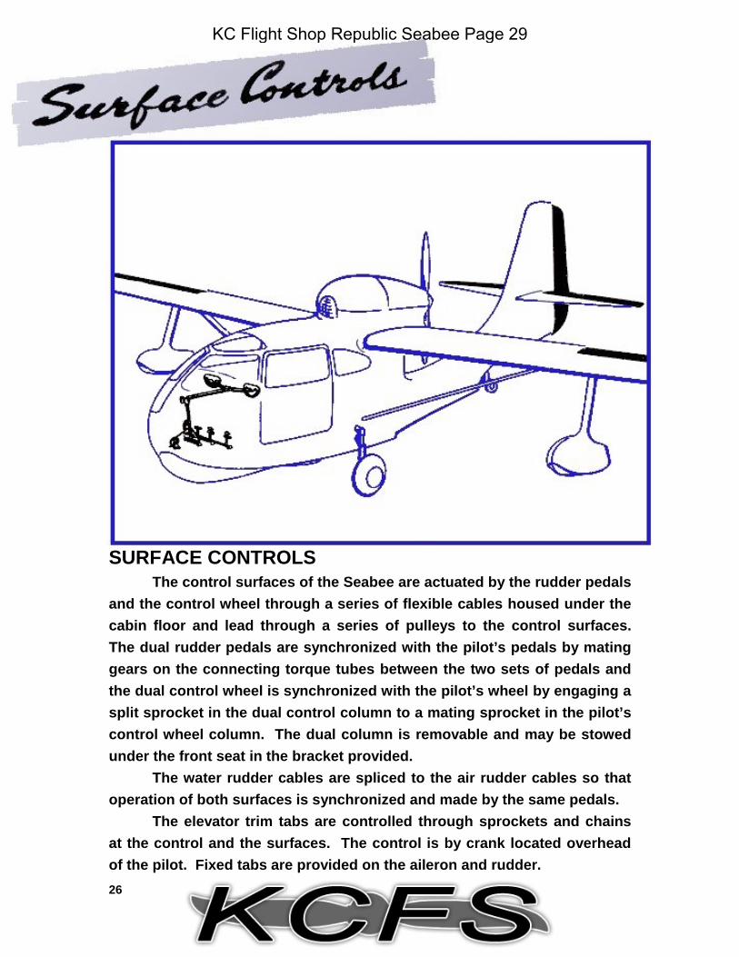
SURFACE CONTROLSThe control surfaces of the Seabee are actuated by the rudder pedals
and the control wheel through a series of flexible cables housed under thecabin floor and lead through a series of pulleys to the control surfaces.The dual rudder pedals are synchronized with the pilot’s pedals by matinggears on the connecting torque tubes between the two sets of pedals andthe dual control wheel is synchronized with the pilot’s wheel by engaging asplit sprocket in the dual control column to a mating sprocket in the pilot’scontrol wheel column. The dual column is removable and may be stowedunder the front seat in the bracket provided.
The water rudder cables are spliced to the air rudder cables so thatoperation of both surfaces is synchronized and made by the same pedals.
The elevator trim tabs are controlled through sprockets and chainsat the control and the surfaces. The control is by crank located overheadof the pilot. Fixed tabs are provided on the aileron and rudder.
KC Flight Shop Republic Seabee Page 29
27
SURFACE CONTROL DIAGRAM
KC Flight Shop Republic Seabee Page 30
28
LANDING GEARThe hydraulically controlled landing gear is maintained in the up or
down position by the geometry of the linkage. As noted on the landinggear diagram on the facing page, the linkage is designed so as to “break”during the transition phase of the gear operation and to “remake” at the upor down position, so that the center pivots of the linkage are past deadcenter travel. In this manner, positive lock is maintained until hydraulicpressure is applied to the cylinder permitting a “break” in the linkage.
Note that the tail wheel is rotated to the up and down position andthat the main gear is retracted and extended.
KC Flight Shop Republic Seabee Page 31
29
LANDING GEAR DIAGRAM
KC Flight Shop Republic Seabee Page 32
30
HYDRAULIC SYSTEMThe flaps, main landing gear and the tail wheel are extended and retracted
hydraulically. A single, manually-operated hydraulic pressure system activatesboth the landing gear and the flaps.
A lever, extending upward from beneath the floor between the two frontseats activates the pump with which hydraulic pressure is built up. Two otherarms extending from this unit control the action of the fluid. The right leverdirects the section of the landing gear while the one located on the left sidedetermines the position of the flaps. The hydraulic power pack incorporates aseries of check valves which prevent the temporary dropping off of pressure whentransferring the hydraulic action from wheels to flaps or reverse.
The system has a three and one-half pint capacity and uses a petroleum oilbase hydraulic fluid, Specification 3580D or equivalent.
KC Flight Shop Republic Seabee Page 33
31
HYDRAULIC DIAGRAM
KC Flight Shop Republic Seabee Page 34
32
BRAKE AND WHEELSThe main wheels of the Seabee 7.00 x 8 and the tail wheel is a 10”
smooth contour type.Each main wheel is equipped with bladder-type brake which is fed
from its own master brake cylinder at each of the rudder pedals. A brakeadjuster and a parking valve are installed in each of the lines between themaster brake cylinder and the wheel. The positions of these parking valvesare controlled at the instrument panel by a single parking control lever.
A control is provided in the cockpit to engage or disengage a tailwheel lock thus permitting the tail wheel to be locked in the centeredposition or to be unlocked in order to swivel.
KC Flight Shop Republic Seabee Page 35
33
BRAKE DIAGRAM
KC Flight Shop Republic Seabee Page 36
34
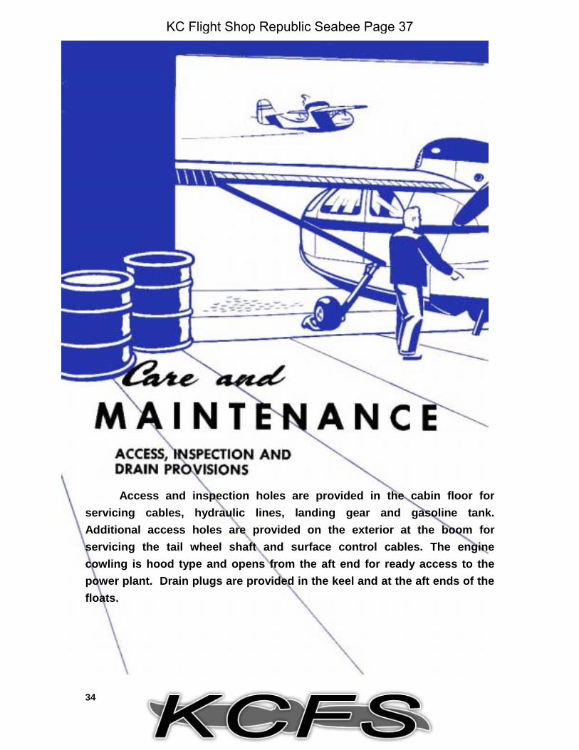
Access and inspection holes are provided in the cabin floor forservicing cables, hydraulic lines, landing gear and gasoline tank.Additional access holes are provided on the exterior at the boom forservicing the tail wheel shaft and surface control cables. The enginecowling is hood type and opens from the aft end for ready access to thepower plant. Drain plugs are provided in the keel and at the aft ends of thefloats.
KC Flight Shop Republic Seabee Page 37
55
GROUND HANDLINGThe best push points for ground handling are the wing struts.
Do not use floats, float struts orempennage for push points.
JACKINGThe base of the oleo and the cross tube will accommodate jacks. To
jack the tail wheel, place jack under aft end of keel.
HOISTING AND LIFTINGHoisting lugs are available for both the engine and the airplane.
Do not lift Seabee by the stabilizer.
LEVELINGLeveling lugs are provided on the door posts for reference in leveling
the Seabee.
ANCHORING AND TOWINGAn anchor cleat is provided at the bow of the airplane. Tow by
attaching suitable harness or tow bars at the landing gear.
KC Flight Shop Republic Seabee Page 38
KC Flight Shop Republic Seabee Page 39
37LU
BR
ICATIO
N C
HAR
T
NOTE: Grease propeller with AN-G-15 every 25 hours or more frequently to assure free blade action.
KC Flight Shop Republic Seabee Page 40
38
GEN
ERAL SER
VICIN
G PO
INTS
KC Flight Shop Republic Seabee Page 41
39
GEN
ERAL SER
VICIN
G C
HAR
T
KC Flight Shop Republic Seabee Page 42
40
SERVICING THE SHOCK ABSORBER STRUTThe following service instructions when followed will result in a rapid
and proper servicing of your shock absorber. All references used in thisoutline pertain to the illustration shown.
Instructions are given for both pressure readings andmeasurements. Before attempting to take an extension measurement theairplane must be vigorously rocked. This is necessary since the gear isequipped with packing and is subject to the usual binding loads. It is alsorecommended that the gear be inflated to a higher pressure and the air bledto achieve proper extension, rather than try to build up the proper pressureby lifting the entire airplane with air pressure.
The fluid level should be checked with the gear in the fullycompressed condition before inflation. Before attempting to add to orcheck the fluid it is absolutely necessary to first bleed off any air that mightbe present by depressing the air valve. When all air has escaped the valvehousing may be removed so that fluid can be added.
1. Depress air valve (A). Allow all air to escape.2. Rock airplane vigorously. Check dimension (X) for full compression. This should be 2 7/16 inches.3. Remove air valve body (A) and fill to overflowing with petroleum oil base hydraulic fluid Specification AAF-3580D or equivalent.
DO NOT USE ALCOHOL OR CASTOR OIL BASE FLUIDS IN SEABEE STRUTS!4. Replace and tighten air valve body and with the airplane in the empty weight condition, inflate to approximately 140-150 psi. Rock the airplane vigorously to get a true extension reading at “X”. This should be 6½” ± ¼”.5. If necessary to obtain this reading, slowly bleed the air valve, rocking the Seabee at intervals until the desired dimension has been reached.6. Should the gas tanks be full but the airplane otherwise empty inflate to approximately 190-200 psi. Bleed air pressure, rocking airplane at intervals until the “X” dimension is 5” ± ¼”.7. To service the gear on a jacked-up plane, the strut should be inflated to 53 psi ±± 5 psi. This should indicate full extension of 10 7/16” ± ¼”.
KC Flight Shop Republic Seabee Page 43
41
REMOVAL OF WHEEL AXLEIn removing the axle from the strut, the air must be completely
removed from the strut before the axle itself is touched. The air valve bodymust not only be loosened, but must be removed when sufficient air hasescaped to safety permit this. This is necessary because even with the airvalve in the open position there still remains enough trapped air to pushdown on the lower sealing ring as the axle is removed. This force althoughslight could injure the mechanic performing this operation.
When the air pressure has been removed from the strut, loosen andremove the bolt (B) in the lower portion of the strut and extract the axle. Asan added safety precaution, a soft metal mandrel should be used to tap theaxle out of the strut.
KC Flight Shop Republic Seabee Page 44
42
TIE-DOWN AND MOORINGTie-down rings for tie-down and mooring are provided at the
outboard side of each float strut and at the aft end of the boom. The aftend should be tied to two points as noted in the illustration below.
When tying-down, leave tail wheel in fore and aft direction.
Use manila rope of at least 5/8” diameter for tie-down.
When facing into the wind, use spoilers.
If the area is dusty or heavy snow is falling use covers overplexiglass areas.
If locking boards or control locks of any kind are used, place aconspicuous warning in the cockpit.
KC Flight Shop Republic Seabee Page 45
43
CONTROL SETTINGSNeutral setting of the controls is accomplished as indicated in the
diagram shown below.With the exception of the trim tab and water rudder cables which are
adjusted to hand-tight tension, cables for all control surfaces are adjustedto 20 ±± 5 pounds.
Adjustments for surface travel are made at the adjustable rod endswhich actuate the surfaces; angular travel of all surfaces is:
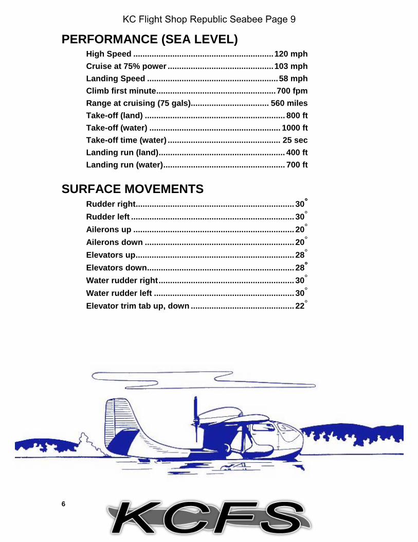
Elevators 28°° up 28°° downElevator trim tabs 22°° up 22°° downAileron 20°° up 20°° downRudder 30°° left 30°° rightWater rudder 30°° left 30°° rightFlaps --------- 30°° down
KC Flight Shop Republic Seabee Page 46
44
UPHOLSTERYThe upholstery is a plastic coated fabric which may be cleaned with
soap and water and further protected by waxing.EXTERIOR SURFACES
The exterior surfaces of the Seabee can best be protected with acoating of high-grade wax.
Salt water spray should not be allowed to remain on the surfaces forextended periods; washing with clear water is recommended.
PLEXIGLASSThe plexiglass areas of the Seabee must be cleaned with grit free
agents; such as, soap and water, or a dilute water solution of a syntheticwetting agent. Kerosene or white gasoline may be used to remove greaseor oil.
Do not use plexiglass solvents or abrasives;such as, benzene, carbon tetrachloride, lacquer thinner,
kitchen scouring powders, etc.
To clean, a soft sponge or rag may be used, but it is preferable touse bare hand thus insuring grit free cleaning.
KC Flight Shop Republic Seabee Page 47
45
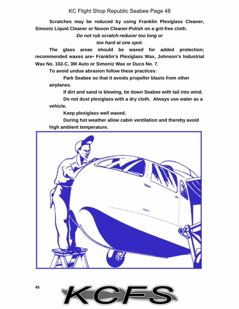
Scratches may be reduced by using Franklin Plexiglass Cleaner,Simoniz Liquid Cleaner or Noxon Cleaner-Polish on a grit-free cloth.
Do not rub scratch-reducer too long ortoo hard at one spot.
The glass areas should be waxed for added protection;recommended waxes are- Franklin’s Plexiglass Wax, Johnson’s IndustrialWax No. 102-C, 3M Auto or Simoniz Wax or Duco No. 7.
To avoid undue abrasion follow these practices:Park Seabee so that it avoids propeller blasts from other
airplanes.If dirt and sand is blowing, tie down Seabee with tail into wind.Do not dust plexiglass with a dry cloth. Always use water as a
vehicle.Keep plexiglass well waxed.During hot weather allow cabin ventilation and thereby avoid
high ambient temperature.
KC Flight Shop Republic Seabee Page 48
46
WHEELSTo remove wheels it is necessary to release the parking brake and
brake adjusters so that pressure is relieved on the wheel brakes.BRAKES
The master cylinders are equipped with O-ring type synthetic rubberpacking. Fluid is admitted into the master cylinder by removing the screwat the top of the cylinder. The vent hole in the filler screw must be clear atal times.
Brake pedals should respond with firmness when depressed.Sponginess or softness of brake pedal denotes presence of air in thesystem. If brake pedal is firm but slowly and steadily requires further pedaldepression, leakage past rings is indicated. Worn rings may be replacedby disassembly of the defective unit.
Gravity bleeding is inefficient on the Seabee brake installation. Inorder to bleed system properly, pressure type bleeding is necessary. Thismay be done by attaching hoses at the wheel and master brake cylindersand pumping fluid up from the wheel cylinder until escaped fluid at themaster cylinder is clear of air bubbles.
The wheel brake is an expander type brake.
KC Flight Shop Republic Seabee Page 49
47
BRAKE ADJUSTMENTTo readjust the brake linings for wear, turn the brake adjusters
clockwise as far as possible and push the brake pedals hard. This actionwill lock the wheels; then back off on the adjusters until the wheels may beturned by hand against a slight drag. Before bleeding, loosen adjusters;after bleeding, readjust brakes as above.
TAIL WHEEL UPSTOPTail wheel upstop adjustment is made as shown in the following
illustration.
KC Flight Shop Republic Seabee Page 50
48
LANDING GEAR SIGNAL SWITCHESLanding gear signal switches are located in the hull and are actuated
by a lever on a shaft. Adjustment screws, which depress the switches, areinstalled on the lever; these screws are adjusted so that the switches aretripped at the up and down position of the gear.
CYLINDER ADJUSTMENTSAdjustment for the main gear lock is made at rod end of retracting
cylinder; adjust rod end so pins and leer are under moderate pinch.
KC Flight Shop Republic Seabee Page 51
49
FUEL-FLOW SHUT-OFFAdjustment of the fuel-flow shut-off control is indicated in the
illustration below:
VALVE ADJUSTMENTSSince the Franklin “500” is equipped with hydraulic valve lifters
which automatically compensate for variations in engine clearances, rockeradjustment is seldom necessary. Before adjustments are made, oil mustbe bled out of the lifter bodies; adjustments are then made in the samegeneral sequence of operation as is applied on most other aircraft engines.
KC Flight Shop Republic Seabee Page 52
50
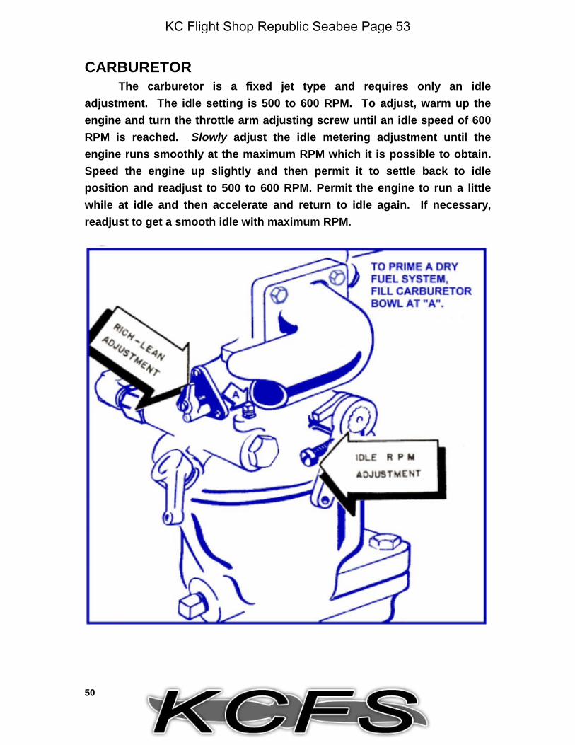
CARBURETORThe carburetor is a fixed jet type and requires only an idle
adjustment. The idle setting is 500 to 600 RPM. To adjust, warm up theengine and turn the throttle arm adjusting screw until an idle speed of 600RPM is reached. Slowly adjust the idle metering adjustment until theengine runs smoothly at the maximum RPM which it is possible to obtain.Speed the engine up slightly and then permit it to settle back to idleposition and readjust to 500 to 600 RPM. Permit the engine to run a littlewhile at idle and then accelerate and return to idle again. If necessary,readjust to get a smooth idle with maximum RPM.
KC Flight Shop Republic Seabee Page 53
51
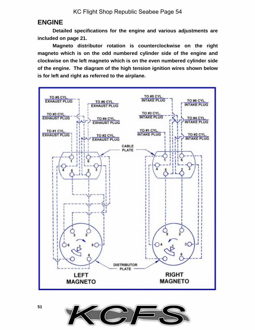
ENGINEDetailed specifications for the engine and various adjustments are
included on page 21.Magneto distributor rotation is counterclockwise on the right
magneto which is on the odd numbered cylinder side of the engine andclockwise on the left magneto which is on the even numbered cylinder sideof the engine. The diagram of the high tension ignition wires shown belowis for left and right as referred to the airplane.
KC Flight Shop Republic Seabee Page 54
52
10-HOUR INSPECTION (For preflight inspection, see page 11)Clean out gasoline strainer to insure a flow of clean gasoline to the
carburetor.
Check for water accumulation in the hull and floats.See that cylinder cooling fins are clean.Make a thorough check of the engine compartment for cleanliness
and loose parts.Check for any oil or gasoline leaks.
KC Flight Shop Republic Seabee Page 55
53
25-HOUR INSPECTIONDrain engine oil while hot and replace with new engine oil. When
operating under dusty conditions, change oil more often than every 25hours of operation.
Check breaker point clearances.
KC Flight Shop Republic Seabee Page 56
54
Check instruments for correct operation.
Check all high tension wires and connections at the plugs andmagnetos for tight connections and proper insulation.
Inspect exhaust manifold as to general condition, fastening, gaskets,etc.
Check cowling.Check engine mount for tightness of connecting bolts, for cracks,
dents and other defects. Check for evidence of misalignment and wear ofshock mounts.
Check that all vents are clear.Very carefully inspect all seams of the hull and structure both
interior and exterior for any evidence of corrosion. Remove fairings inorder to make a complete inspection.
KC Flight Shop Republic Seabee Page 57
55
Check all fairings for cracks.Check cables for tensions and for fraying. Replace frayed cables.Lubricate all components as indicated on the lubrication diagram.Check flaps through full operation.Check oleos and tires for proper inflation.Check first aid kit and fire extinguisher.Check propeller for track, general condition and tightness of hub.
Check the fluid level in the brakes, oleos and hydraulic systems andreplenish where necessary.
Inspect all hydraulic cylinders for leakage past packings.Check battery for charge and replenish cells to proper level with
distilled water.Examine safety belt and catches for security of attachment and wear.Remove wheels and check brake linings for wear.
KC Flight Shop Republic Seabee Page 58
56
50-HOUR INSPECTIONRepeat 10 and 25 hour inspections.Check throttle, mixture and carburetor heat controls.Check all rubber and flexible hose connections.Check for oil, dirt, water or other accumulations in the hull.Check all engine controls for free operation.
100-HOUR INSPECTIONRepeat 10, 25 and 50 hour inspections.
Remove and check all spark plugs; set gaps for .014 to .018 inch.Check plugs for proper operation after gapping and before installation. Toinstall plugs, turn by hand until plugs are seated on gaskets and thentighten to 15 to 20 ft. lbs. torque.
Drain pitot lines.Check seat cushions for rips and tears.Check plexiglass for scratches and bruises which may affect
visibility.
KC Flight Shop Republic Seabee Page 59
Kevin
Typewritten Text
KCFS Republic Rc-3 Seabee Team KCFS Developers
Kevin Miller 3D modeling, texturing and animation.
Chuck Jordy Simulator integration
Bernt Stolle Flight modeling
Beta Testers
Rick “Papab” Brown, Larry “Tako_Kichi” Green, Chris “Railrunner130” Coarse, Jan Kees Blom, Rob de Vries, OleBoy, Ben Dean, Zach Sweetser
Special Thanks
Seabee Pilots and Owners.
Bruce Hinds of N12CX
Tom Hoag of N217G
Mikel Shay of N6517K
Bob Ghould of N6255K
Stephen Taylor of N6755K
D. Michael Holdridge
Steinar of http://www.seabee.info/
Steve of http://www.republicseabee.com/
Everyone at the Yahoo Seabee Group at http://groups.yahoo.com/group/Seabee/
Also a very special thanks to all of our wives and family that put up with our “hobby”.