32
SEAD Distribution Transformers Report Part 2: Test Method Review December 19, 2013

SEAD Distribution Transformers Report Part 2:
Test Method Review
December 19, 2013

Part 2 – Test Method Review
1
SEAD Standards & Labelling Working Group Distribution Transformers Collaboration Part 2: Test Method Review Report A report containing information about the different international test methods for measuring the efficiency of distribution transformers
Prepared for: Terry Brennan, Natural Resources Canada Steve Pantano and Jenny Corry, CLASP Submitted by: Michael Scholand, N14 Energy Limited Trevor Blackburn, TR & JR Blackburn Consulting Phil Hopkinson, HVOLT Inc. Mahesh Sampat, EMS International Consulting
December 2013

Part 2 – Test Method Review
2
ABOUT SEAD The Super-efficient Equipment and Appliance Deployment (SEAD) Initiative, a five-year, US$20 million initiative under the Clean Energy Ministerial (CEM) and the International Partnership for Energy Efficiency Cooperation (IPEEC), helps turn knowledge into action to accelerate the transition to a clean energy future through effective appliance and equipment energy efficiency programs. SEAD is a multilateral, voluntary effort among Australia, Brazil, Canada, the European Commission, France, Germany, India, Japan, South Korea, Sweden, the United Arab Emirates, the United Kingdom, and the United States. The Collaborative Labeling and Appliance Standards Program (CLASP), a non-profit organization with deep experience in supporting international appliance efficiency efforts, serves as the Operation Agent for SEAD. For more information about SEAD, please visit: www.superefficient.org. COMMENTS This report is one part of a four part study which taken together presents an overview of distribution transformer losses globally, the savings potential, the technology options for improvement, and a comparison of some of the efficiency programmes from around the world. The intended audience for this four part study includes policy makers and the technical advisors who work with them on designing and developing sustainable market transformation programmes. CLASP contracted N14 Energy Limited to prepare these reports, and Michael Scholand of N14 Energy would welcome any comments or suggestions relating to the report at the following email address (change the “[at]” to “@”): MScholand [at] n14energy.com

Part 2 – Test Method Review
3
Table of Contents
1 TRANSFORMER TEST METHODS............................................................................................ 6 1.1 WHY HAVE A HARMONISED TEST STANDARD? .................................................................................... 6 1.2 IEC 60076 POWER TRANSFORMERS ................................................................................................. 8 1.3 IEC MEASUREMENT METHOD FOR LOSSES ....................................................................................... 15
1.3.1 MEASUREMENT OF IMPEDANCE AND LOAD LOSS ........................................................................ 15 1.3.2 MEASUREMENT OF NO-LOAD LOSS .......................................................................................... 16
2 COMPARISON OF TEST STANDARDS ................................................................................... 19 2.1 GENERAL TEST CONDITIONS ........................................................................................................... 19 2.2 MEASUREMENT OF NO-LOAD LOSSES .............................................................................................. 20 2.3 MEASUREMENT OF LOAD LOSSES .................................................................................................... 22
3 ACHIEVING A GLOBALLY HARMONISED TEST STANDARD ..................................................... 25 3.1 EFFICIENCY OR MAXIMUM LOSSES................................................................................................... 25 3.2 DEFINING EFFICIENCY .................................................................................................................... 27 3.3 SELECTING A LOADING POINT ......................................................................................................... 29 3.4 MEASUREMENT ACCURACY ............................................................................................................ 30
List of Tables TABLE 1-1. LIST OF STANDARDS FOR IEC 60076 POWER TRANSFORMERS ................................................. 9
TABLE 2-1. COMPARISON IEC AND IEEE FOR GENERAL TEST CONDITIONS ............................................... 20
TABLE 2-2. COMPARISON IEC AND IEEE FOR MEASUREMENT OF NO-LOAD LOSSES .................................. 21
TABLE 2-3. COMPARISON IEC AND IEEE FOR MEASUREMENT LOAD LOSSES ............................................ 23
TABLE 3-1. SAMPLE OF KVA RATINGS FOR CHINA’S THREE-PHASE LIQUID-IMMERSED GRADE 3 MEPS ........ 26
TABLE 3-2. ILLUSTRATIVE COMPARISON OF KVA RATING CONVENTIONS, IEC AND IEEE ............................. 28
List of Figures FIGURE 2-1. EXCERPT FROM US DOE TEST PROCEDURE FOR DISTRIBUTION TRANSFORMERS ...................... 24
FIGURE 3-1. EFFICIENCY CHANGES WITH LOADING, REACHES PEAK WHERE NL = LL .................................. 30
Part 2 – Test Method Review
4
Acronyms and Abbreviations AC Alternating Current BEE Bureau of Energy Efficiency (India) BIL Basic Impulse Insulation Level CEM Clean Energy Ministerial CENELEC European Committee for Electrotechnical Standardisation CFR Code of Federal Regulations (United States) CGO Conventional Grain Oriented CLASP Collaborative Labeling and Appliance Standards Program CNIS China National Institute of Standardization CO2 Carbon Dioxide CSA Canadian Standards Association DOE Department of Energy (United States) EC European Commission ECCJ Energy Conservation Centre Japan EECA Energy Efficiency and Conservation Authority (New Zealand) EU European Union HEPL High Efficiency Performance Level Hz Hertz IEC International Electrotechnical Commission kg kilogram kV kilovolt (i.e., thousand volts) kVA kilovolt-ampere kW kilowatt LCC life-cycle cost MEPS Minimum Energy Performance Standards MVA megavolt-ampere MWh megawatt-hours NEMA National Electrical Manufacturers Association Pk load-dependent coil losses (winding losses) Po no-load losses in the core R&D Research and Development SEEDT Strategies for Energy Efficient Distribution Transformers SWER Single Wire Earth Return TCO Total Cost of Ownership TOC Total Ownership Cost US United States W Watts

Part 2 – Test Method Review
5
Consistent Terminology There are many different naming conventions in practice around the world for the types of distribution transformers and their losses. The table below provides some of the examples of terminology used in the various documents reviewed, and the equivalent terms that will be used in this report for simplicity and consistency.
Examples of Terminology Used Term Used in
this Report
Oil-filled, oil-immersed, liquid-immersed, liquid-filled Liquid-filled
Dry-type, open ventilated, cast-coil, resin-coil, epoxy-coil, encapsulated-winding Dry-type
Core losses, iron losses, no-load losses, steel losses Core loss
Coil losses, copper losses, winding losses, load losses Coil loss
In this report, the terms “European Union” and “Europe” may be used interchangeably, however the intention is always to represent the twenty-eight member states of the European Union and the three countries of the European Economic Area. Together, this group includes: Austria, Belgium, Bulgaria, Croatia, Cyprus, the Czech Republic, Denmark, Estonia, Finland, France, Germany, Greece, Hungary, Iceland, Ireland, Italy, Latvia, Liechtenstein, Lithuania, Luxembourg, Malta, The Netherlands, Norway, Poland, Portugal, Romania, Slovakia, Slovenia, Spain, Sweden and the United Kingdom. For these countries, the European Commission is in the process of establishing a MEPS requirement that would apply to distribution transformers in the European Union and European Economic Area countries.

Part 2 – Test Method Review
6
1 Transformer Test Methods
The purpose of a transformer is to convert power from one system voltage to another. For a distribution transformer, this voltage relationship, or voltage ratio, is determined by the ratio of the number of turns on the high voltage winding to the number of turns on the low voltage winding. As the alternating current in the high voltage winding changes polarity 50 or 60 times a second (called “Hertz”), it induces a current in the low voltage winding that is proportional to the voltage of the high voltage winding divided by the ratio of the number of turns. As the transformer works, it incurs power (and thus energy) losses in the high voltage winding, the low voltage winding, the core steel and in the surrounding transformer tank / housing and fittings (called stray losses). The magnitude of these losses relative to the power throughput determines the efficiency of the transformer. While there are many aspects of a distribution transformer that can be measured, this report is focusing on a comparison of how mandatory and voluntary energy-efficiency programmes for distribution transformers measure performance. This report sets the context for distribution transformer testing. This chapter presents an introduction to transformer testing, addressing issues like why it is important to have harmonised test standards and identifying the complete list of IEC standards. Chapter 2 provides a comparison of the different test methods, in an effort to identify common areas and differences. Chapter 3 discusses a joint collaboration between IEC and IEEE, and discusses why the recommendations from this study are based on percentage energy-efficiency at 50% loading. In a separate report, “Part 4: Country Profiles for Internationally-Comparable Test Methods and Efficiency Class Definitions for Distribution Transformers”, a country-by-country comparison is presented, which provides some information on the energy-efficiency policies and programmes, as well as how transformers are tested by different countries around the world.
1.1 Why Have a Harmonised Test Standard?
Testing standards underpin all product standards and labelling programmes because they are the means by which product energy performance is measured and compared. Harmonisation of energy performance test procedures is a means of facilitating technology diffusion and trade objectives. Harmonised test methods encourage trade, conformity assessment, comparison of performance levels, technology transfer and the accelerated adoption of best practice policy. For example, if energy efficiencies are to used internationally in performance schemes and if transformers are to be imported/exported, it is necessary to specify the measurement accuracies (or uncertainty levels) of test methods to ensure that the manufacturer, the customer and the energy regulator all get the same result when testing distribution transformers. A test standard adopted for regulatory purposes must meet the following objectives:
Coverage - the testing standard scope must cover that of the regulated product;
Metric – the testing standard must be capable of determining energy consumption, efficiency or other metric that constitutes the basis of the regulation;
Part 2 – Test Method Review
7
Accurate – is designed to minimise random or systemic errors, establishes maximum margins of error and avoids the use of optional approaches;
Representative - provides robust measurement of energy consumption reflective of in-situ energy use under conditions where the product is used;
Repeatable - gives the same result each time a product is tested in the same laboratory;
Reproducible - gives the same result each time a product is tested in different laboratories;
Low cost – is not overly expensive or time consuming to conduct, and balances the robustness of the test and cost of testing; and
Portable (optional) – if necessary, should be designed to be applied on-site with separate energy source generation (e.g., large distribution transformers can be difficult to transport to laboratories).
Both governments and manufacturers stand to gain from the harmonisation of testing methods. Benefits to governments include:
lower development costs for preparing a test method;
comparative test results for products sold domestically and in neighbouring economies;
the ability to transpose and adapt analyses from other markets to determine appropriate domestic efficiency requirements;
adopting minimum performance thresholds and applying them as a starting point in a domestic regulatory programme;
adopting a common set of upper thresholds that can be used for market pull programmes such as labelling and incentive schemes; and
faster and less expensive testing – for compliance and other purposes – as harmonised testing creates a larger choice of laboratories who can conduct product tests.
For manufacturers, having one harmonised test method with specified measurement uncertainties used by markets around the world will reduce testing costs associated with demonstrating regulatory and/or product labelling compliance. In an ideal world, the manufacturers need only conduct one test and the result would be universally accepted by these markets as being accurate and representative of the performance of their product. A harmonised test method also enables them to look ahead to longer-term rewards for innovation around advanced product designs that will be more energy-efficient and have lower life-cycle costs for consumers. Having a consistent test method enables countries to establish a common set of efficiency thresholds that would not only be broad enough to encompass all current market circumstances but which also include aspirational efficiency thresholds as pointers for future market development. The most widely used test method today for measuring distribution transformers is based on the International Electrotechnical Commission (IEC) 60076 series of test standards, which are continually updated by the various committees and subcommittees working on these

Part 2 – Test Method Review
8
standards. The following section provides a summary of the IEC 60076 family of test standards.
1.2 IEC 60076 Power Transformers
The IEC is a worldwide organisation for standardisation made up of national electrotechnical committees. The objective of the IEC is to promote international co-operation on all questions concerning standardisation in the electrical and electronic fields. The IEC, therefore, prepares and publishes international testing standards through technical committees made up of representatives from any IEC National Committees who are interested. International, governmental and non-governmental organisations also participate in this process. The IEC collaborates closely with the International Organisation for Standardisation (ISO) in accordance with conditions determined by agreement between the two organisations. The formal decisions or agreements of the IEC on technical matters are intended to represent, as nearly as possible, an international consensus of opinion on the relevant subjects since each technical committee has representation from all interested National Committees. The documents published have the form of recommendations for international use and are published as standards, technical specifications, technical reports or guides. In order to promote international harmonisation, IEC National Committees generally undertake to apply IEC International Standards transparently to the maximum extent possible within their national and regional standards. Any deviation from the IEC standard is usually clearly indicated in the national or regional standard. That said, most member countries of the IEC have now moved to have their own national electrical Standards identical with the appropriate IEC Standards, thus facilitating international uniformity. The set of international standards published under IEC 60076, Power Transformers, were prepared by IEC Technical Committee 14. The following table lists the 19 published standards documents.

Part 2 – Test Method Review
9
Table 1-1. List of Standards for IEC 60076 Power Transformers
IEC Standard Title of IEC Standard for Power Transformers
IEC 60076-1 ed3.0 (2011-04) Part 1: General
IEC 60076-2 ed3.0 (2011-02) Part 2: Temperature rise for liquid-immersed transformers
IEC 60076-3 ed3.0 (2013-07) Part 3: Insulation levels, dielectric tests and external clearances in air
IEC 60076-4 ed1.0 (2002-06) Part 4: Guide to the lightning impulse and switching impulse testing - Power transformers and reactors
IEC 60076-5 ed3.0 (2006-02) Part 5: Ability to withstand short circuit
IEC 60076-6 ed1.0 (2007-12) Part 6: Reactors
IEC 60076-7 ed1.0 (2005-12) Part 7: Loading guide for oil-immersed power transformers
IEC 60076-8 ed1.0 (1997-10) Part 8: Application guide
IEC 60076-10 ed1.0 (2001-05) Part 10: Determination of sound levels
IEC 60076-10-1 ed1.0 (2005-10)
Part 10-1: Determination of sound levels - Application guide
IEC 60076-11 ed1.0 (2004-05) Part 11: Dry-type transformers
IEC 60076-12 ed1.0 (2008-11) Part 12: Loading guide for dry-type power transformers
IEC 60076-13 ed1.0 (2006-05) Part 13: Self-protected liquid-filled transformers
IEC 60076-14 (2013-09) Part 14: Design and application of liquid-immersed power transformers using high-temperature insulation materials
IEC 60076-15 ed1.0 (2008-02) Part 15: Gas-filled power transformers
IEC 60076-16 ed1.0 (2011-08) Part 16: Transformers for wind turbine applications
IEC 60076-18 ed1.0 (2012-07) Part 18: Measurement of frequency response
IEC/TS 60076-19 ed1.0 (2013-03)
Part 19: Rules for the determination of uncertainties in the measurement of losses in power transformers and reactors
IEC 60076-21 ed1.0 (2011-12) Part 21: Standard requirements, terminology, and test code for step-voltage regulators
Note: this list is current as of September 2013.
Part 2 – Test Method Review
10
IEC 60076-1 ed3.0 (2011-04) - Power transformers - Part 1: General This part of IEC 60076 applies to three-phase and single-phase power transformers (including auto-transformers) with the exception of certain categories of small and special transformers.1 When IEC standards do not exist for certain categories of transformers, this part of IEC 60076 may still be applicable either as a whole or in part. For those categories of power transformers and reactors which have their own IEC standards, this part is applicable only to the extent in which it is specifically called up by cross-reference in the other standard. The updated edition of this standard includes the following technical sections that were not in the previous version:
- definition of harmonic content; - subclause on transport; - functional method of specification; - connection symbols for single phase transformers; - safety and environmental requirements; - requirements for liquid preservation systems; - clause on DC currents; - vacuum, pressure and leak tests on tanks; - facilities for condition monitoring and environmental and safety
considerations. IEC 60076-2 ed3.0 (2011-02) - Power transformers - Part 2: Temperature rise for liquid-immersed transformers
This standard applies to liquid-immersed transformers, identifies power transformers according to their cooling methods, defines temperature rise limits and gives the methods for temperature rise tests. This new edition includes the following significant technical changes with respect to the previous edition:
- the winding hot-spot temperature rise limit was introduced among the prescriptions;
- the procedures for the temperature rise test were improved in relation to the new thermal requirements;
- five informative annexes were added in order to facilitate the implementation of this standard.
1 Examples of small and special transformers not covered under 60076-1 are: (1) single-phase transformers
with rated power less than 1 kVA and three-phase transformers less than 5 kVA; (2) transformers, which have no windings with rated voltage higher than 1 000 V; (3) instrument transformers; (4) traction transformers mounted on rolling stock; (5) starting transformers; (6) testing transformers; (7) welding transformers; (8) explosion-proof and mining transformers; and (9) transformers for deep water (submerged) applications.

Part 2 – Test Method Review
11
IEC 60076-3 ed3.0 (2013-07) - Power transformers - Part 3: Insulation levels, dielectric tests and external clearances in air
IEC 60076-3:2013 specifies the insulation requirements and the corresponding insulation tests with reference to specific windings and their terminals. This International Standard applies to power transformers as defined by IEC 60076-1. It also recommends external clearances in air. It gives details of the applicable dielectric tests and minimum dielectric test levels. Recommended minimum external clearances in air between live parts and between live parts and earth are given for use when these clearances are not specified by the purchaser. For categories of power transformers and reactors which have their own IEC standards, this standard is applicable only to the extent in which it is specifically called up by cross reference in the other standards. This third edition of IEC 60076-3 cancels and replaces the second edition published in 2000, and constitutes a technical revision.
IEC 60076-4 ed1.0 (2002-06) - Power transformers - Part 4: Guide to the lightning impulse and switching impulse testing - Power transformers and reactors
This standard gives guidance and explanatory comments on the existing procedures for lightning and switching impulse testing of power transformers to supplement the requirements of IEC 60076-3. Also generally applicable to the testing of reactors (see IEC 60289), modifications to power transformer procedures being indicated where required. The standard provides information on waveshapes, test circuits including test connections, earthing practices, failure detection methods, test procedures, measuring techniques and interpretation of results.
IEC 60076-5 ed3.0 (2006-02) - Power transformers - Part 5: Ability to withstand short circuit
This standard identifies the requirements for power transformers to sustain without damage the effects of overcurrents originated by external short circuits. It describes the calculation procedures used to demonstrate the thermal ability of a power transformer to withstand such overcurrents and both the special test and the theoretical evaluation method used to demonstrate the ability to withstand the relevant dynamic effects.
IEC 60076-6 ed1.0 (2007-12) - Power transformers - Part 6: Reactors
The standard applies to the following types of reactors: shunt reactors; series reactors including current-limiting reactors, neutral-earthing reactors, power flow control reactors, motor starting reactors, arc-furnace series reactors; filter (tuning) reactors; capacitor damping reactors; capacitor discharge reactors; earthing transformers (neutral couplers); arc-suppression reactors; smoothing reactors for HVDC and industrial application.

Part 2 – Test Method Review
12
IEC 60076-7 ed1.0 (2005-12) - Power transformers - Part 7: Loading guide for oil-immersed power transformers
This standard is applicable to oil-immersed transformers and describes the effect of operation under various ambient temperatures and load conditions on transformer life.
IEC 60076-8 ed1.0 (1997-10) - Power transformers - Part 8: Application guide
This standard provides information to users about certain fundamental service characteristics of different transformer connections and magnetic circuit designs; system fault currents; parallel operation of transformers, calculation of voltage drop or rise under load; selection of rated quantities and tapping quantities; application of transformers of conventional design to convertor loading; measuring techniques and so on. This standard cancels and replaces IEC 60606.
IEC 60076-10 ed1.0 (2001-05) - Power transformers - Part 10: Determination of sound levels
This standard defines sound pressure and sound intensity measurement methods by which sound power levels of transformers, reactors and their associated cooling auxiliaries may be determined. Is applicable to transformers and reactors covered by the IEC 60076 series and the IEC 61378 series, without limitation as regards size or voltage and when fitted with their normal cooling auxiliaries.
IEC 60076-10-1 ed1.0 (2005-10) - Power transformers - Part 10-1: Determination of sound levels - Application guide
This standard provides supporting information to help both manufacturers and purchasers apply the measurement techniques described in IEC 60076-10. This standard describes the sources and characteristics of transformer and reactor sound, provides practical guidance on making measurements, and discusses factors that may influence the accuracy of the methods. It applies to transformers and reactors together with their associated cooling auxiliaries.
IEC 60076-11 ed1.0 (2004-05) - Power transformers - Part 11: Dry-type transformers
This standard applies to dry-type power transformers (including auto-transformers) having values of highest voltage for equipment up to and including 36 kV and at least one winding operating at greater than 1,1 kV. This standard applies to all construction technologies.

Part 2 – Test Method Review
13
IEC 60076-12 ed1.0 (2008-11) - Power transformers - Part 12: Loading guide for dry-type power transformers
This standard applies to dry-type transformers according to the scope of IEC 60076-11. It provides the means to estimate ageing rate and consumption of lifetime of the transformer insulation as a function of the operating temperature, time and the loading of the transformer.
IEC 60076-13 ed1.0 (2006-05) - Power transformers - Part 13: Self-protected liquid-filled transformers
The standard applies to high-voltage/low-voltage self-protected liquid-filled and naturally cooled transformers for rated power 50 kVA to 1 000 kVA for indoor or outdoor use having a primary winding (high-voltage) with highest voltage for equipment up to 24 kV; a secondary winding (low-voltage) with highest voltage for equipment of 1,1 kV.
IEC 60076-14 ed2.0 (2013-09) - Power transformers - Part 14: Design and application of liquid-immersed power transformers using high-temperature insulation materials
This standard provides specification, design, testing and loading information for use by both the manufacturer and user of liquid-immersed power transformers employing either high-temperature insulation or combinations of high-temperature and conventional insulation. Is applicable to:
- power transformers designed in accordance with IEC 60076-1; - convertor transformers designed to IEC 61378 series; - arc furnace transformers; and - covers the use of various liquid and solid insulation combinations.
This new edition includes the following significant technical changes with respect to the previous edition:
- enhancement of insulation system descriptions; - clarification of temperature rise limits; and - the addition of overload temperature limits.
IEC 60076-15 ed1.0 (2008-02) - Power transformers - Part 15: Gas-filled power transformers
This standard applies to gas-filled power transformers (including auto-transformers) and to all construction technologies. This standard may be applicable as a whole or in parts to other transformers.

Part 2 – Test Method Review
14
IEC 60076-16 ed1.0 (2011-08) - Power transformers - Part 16: Transformers for wind turbine applications
This standard applies to dry-type and liquid-immersed transformers for rated power 100 kVA up to 10 000 kVA for wind turbine applications having a winding with highest voltage for equipment up to and including 36 kV and at least one winding operating at a voltage greater than 1,1 kV.
IEC 60076-18 ed1.0 (2012-07) - Power transformers - Part 18: Measurement of frequency response
This standard covers the measurement technique and measuring equipment to be used when a frequency response measurement is required either on-site or in the factory either when the test object is new or at a later stage. This standard is applicable to power transformers, reactors, phase shifting transformers and similar equipment.
IEC/TS 60076-19 ed1.0 (2013-03) - Power transformers - Part 19: Rules for the determination of uncertainties in the measurement of losses in power transformers and reactors
This standard is a Technical Specification (TS), it illustrates the procedures that should be applied to evaluate the uncertainty affecting the measurements of no-load and load losses during the routine tests on power transformers. Even if the attention is especially paid to the transformers, when applicable the specification can be also used for the measurements of reactor losses, except large reactors with very low power factor.
IEC 60076-21 ed1.0 (2011-12) - Power transformers - Part 21: Standard requirements, terminology, and test code for step-voltage regulators
This standard provides a description of design types, tables of 50 Hz and 60 Hz ratings, supplementary ratings, construction, and available accessories are provided. Methods for performing routine and design tests applicable to liquid-immersed single and three-phase step-voltage regulators are described. Winding resistance measurements, polarity tests, insulation power factor and resistance tests, ratio tests, no load loss and excitation current measurements, impedance and load loss measurements, dielectric tests, temperature tests, routine and design impulse tests, short-circuit tests, control tests, calculated data, and certified test data are covered.
In addition to the above IEC 60076 standards, the Technical Committee 14 (TC 14) on Power Transformers also maintains the following international standards. These standards are outside of the scope of this report, although it is understood that IEC 60616 is more applicable to distribution trnasformers and may become IEC 60076-9 at some point in the future:
Part 2 – Test Method Review
15
IEC 60214-1 ed1.0 (2003-02) - Tap-changers - Part 1: Performance requirements and test methods
IEC 60214-2 ed1.0 (2004-10) - Tap-changers - Part 2: Application guide
IEC/TR 60616 ed1.0 (1978-01) - Terminal and tapping markings for power transformers
IEC 61378-1 ed2.0 (2011-07) - Converter transformers - Part 1: Transformers for industrial applications
IEC 61378-2 ed1.0 (2001-02) - Convertor transformers - Part 2: Transformers for HVDC applications
IEC 61378-3 ed1.0 (2006-04) - Converter transformers - Part 3: Application guide
IEC 62032 ed2.0 (2012-06) - Guide for the Application, Specification and Testing of Phase-Shifting Transformers
1.3 IEC Measurement Method for Losses
Of the given standards identified in section 1.2 above, the procedure to follow on the measurement of losses of a distribution transformer are given in 60076-1. This is true of both liquid-filled and dry-type transformers. For dry-type transformers, the applicable standard is 60076-11, however in sections 15 (“Measurement of Winding Resistance”), 17 (“Measurement of short-circuit impedance and load loss (routine test)”), and 18 (“Measurement of no-load loss and current (routine test)”), all of these sections cross-reference parts of IEC 60076-1. Thus, in addition to all the sections that specify the general requirements for tests, the two key sections from IEC 60076-1 that are the focus of quantifying the energy performance metric for distribution transformers:
IEC 60076-1 Section 11.4 for measurement of load loss
IEC 60076-1 Section 11.5 for measurement of no-load loss
1.3.1 Measurement of Impedance and Load Loss During the load loss and impedance test, a voltage is applied to the terminals of one of winding(s) (typically the high voltage side) of the transformer while the terminals of the windings on the other side (typically the low voltage side) are shorted together. This is called the transformer “short circuit test”. An applied voltage is increased until the current supplied matches the rated current. Losses supplied to the transformer under these conditions are equivalent to the load losses that are incurred during full load operation. Because the applied voltages are much lower than rated voltage in the short circuit test the magnetic field generated in the core is also much lower and thus loss in the core is insignificant in this test. In many cases, because of possible supply voltage limitations, such as can occur in field testing, it is usual to excite from the low voltage side of the transformer and to short circuit the high voltage side terminals.

Part 2 – Test Method Review
16
Load losses are the sum of the DC resistive losses in the windings plus eddy losses due to circulating currents in the winding conductors plus stray losses in the tank, core clamps and other metal parts. The load losses are sensitive to temperature, due to the fact that the winding resistance increases with temperature while stray and eddy losses decrease with temperature. On the test report, the losses are corrected to the reference temperatures, which are given in section 11.1 of the standard. In the United States, this is 75°C for 55°C rise units or 85°C for 65°C rise units. Part of section 11.4, the measurement of short-circuit impedance and load loss is given below2:
11.4 Measurement of short-circuit impedance and load loss The short-circuit impedance and load loss for a pair of windings shall be measured at rated frequency with voltage applied to the terminals of one winding, with the terminals of the other winding short-circuited, and with possible other windings open-circuited. (For selection of tapping for the test, see 6.5 and 6.6). The supplied current should be equal to the relevant rated current (tapping current) but shall not be less than 50 % thereof. The measurements shall be performed quickly so that temperature rises do not cause significant errors. The difference in temperature between the top liquid and the bottom liquid shall be small enough to enable the mean temperature to be determined accurately. The difference in temperature between the top and bottom liquid shall not exceed 5 K. To obtain this result more rapidly, the liquid may be circulated by a pump. The measured value of load loss shall be multiplied with the square of the ratio of rated current (tapping current) to test current. The resulting figure shall then be corrected to reference temperature (11.1). The I2R loss (R being d.c. resistance) is taken as varying directly with the temperature and all other losses inversely with the temperature. The measurement of winding resistance shall be made according to 11.2. The temperature correction procedure is detailed in Annex E. […deleted text relating to impedance measurement…] NOTE 2 The measurement of load loss on a large transformer requires considerable care and good measuring equipment because of the low power factor and the often large test currents. Any errors and external circuit losses should be minimized. Correction for measuring transformer errors and for resistance of the test connections should be applied unless they are obviously negligible (see IEC 60076-8).
1.3.2 Measurement of No-Load Loss The no-load loss is measured using the standard “open-circuit test” on the transformer. By applying an alternating voltage to one side of the transformer, a magnetic flux is established in the core, which induces a voltage across the terminals of the other side. The
2 Text in blue is reproduced from IEC 60076-1 Edition 3b.

Part 2 – Test Method Review
17
exciting current and no load loss or core loss is the energy required to establish (or excite) the magnetic flux in the core. Because the exciting current is much lower than rated current there are no significant winding (I2R) losses in the open circuit test. To obtain accurate values of no load losses, the wave shape of the applied voltage must be a close as possible to a sine wave. A correction for the waveshape variation is made to the measured results. These tests are performed to ensure that the electrical performance of the core is comparable to the calculated values. They verify that the core has been designed and built correctly, that the quality of the core materials is satisfactory and the core is operating in the correct range of flux density. It also enables the transformer to operate in accordance with certain over voltage conditions as specified in the IEEE Standards without exceeding its rated temperature rating. A transformer can have its no load loss and magnetizing currents measured at 90%, 100% and 110% rated voltage. These tests verify that the core will not operate in the saturation level of the core magnetic field during an over voltage condition. Section 11.4 from IEC 60076-1, the measurement no-load loss and current is given below3:
11.5 Measurement of no-load loss and current The no-load loss and the no-load current shall be measured on one of the windings at rated frequency and at a voltage corresponding to rated voltage if the test is performed on the principal tapping, or to the appropriate tapping voltage if the test is performed on another tapping. The remaining winding or windings shall be left open-circuited and any windings which can be connected in open delta shall have the delta closed. Where indicated in 11.1.2 and 11.1.3, the measurement shall also be made at 90 % and 110 % of rated voltage (or appropriate tapping voltage). The transformer shall be approximately at factory ambient temperature. For a three-phase transformer, the selection of the winding and the connection to the test power source shall be made to provide, as far as possible, symmetrical and sinusoidal voltages across the three phases. The test voltage shall be adjusted according to a voltmeter responsive to the mean value of voltage but scaled to read the r.m.s. voltage of a sinusoidal wave having the same mean value. The reading of this voltmeter is U’. At the same time, a voltmeter responsive to the r.m.s. value of voltage shall be connected in parallel with the mean-value voltmeter and its indicated voltage U shall be recorded.
3 Text in blue is copied from IEC 60076-1 Edition 3b.

Part 2 – Test Method Review
18
When a three-phase transformer is tested, the voltages shall be measured between line terminals, if a delta-connected winding is energized, and between phase and neutral terminals if a YN or ZN connected winding is energized. Phase to phase voltages may be derived from phase to ground measurements, but phase to neutral voltages shall not be derived from phase to phase measurements. The test voltage wave shape is satisfactory if the readings U’ and U are equal within 3%. If the difference between voltmeter readings is larger than 3%, the validity of the test is subject to agreement. A larger difference may be acceptable at higher than rated voltage unless this measurement is subject to guarantee. NOTE 1 It is recognized that the most severe loading conditions for test voltage source accuracy are usually imposed by large single-phase transformers.
The measured no-load loss is Pm, and the corrected no load loss is taken as:
Po = Pm (1 + d)
The r.m.s. value of no-load current is measured at the same time as the loss. For a three-phase transformer, the mean value of readings in the three phases is taken. The no load losses shall not be corrected for any effect of temperature. NOTE 2 In deciding the place of the no-load test in the complete test sequence, it should be borne in mind that no-load loss measurements performed before impulse tests and/or resistance measurements are, in general, representative of the average loss level over long time in service, assuming, that the core is not pre-magnetized. That means, if no-load tests are carried out after resistance measurements and/or lightning impulse tests, the core of the transformer should be demagnetized by over-excitation before the no-load test is carried out.

Part 2 – Test Method Review
19
2 Comparison of Test Standards
There are two major standards bodies that set testing specifications for distribution transformers – they are the IEC and the IEEE. As discussed earlier in this report, the IEC has developed, published and maintains 19 standards in the 60076 family of standards as well as a number of standards on tap-changers, terminals and convertor transformers. IEEE, on the other hand, has over 80 standards and guides within their family of standards covering transformers. For the measurement of losses, most countries and economies active on distribution transformers use a test standard based on IEC 60076. In some cases, there are slight (local) modifications that have been made due to specific or unique requirements, however for the most part, the standards are consistent and based on IEC 60076. The countries and economies reviewed for this study that have standards referencing or based on IEC 60076 are: Australia, Brazil, China, Europe, India, Israel, Japan, Korea, Mexico, New Zealand and Vietnam. The United States and Canada, on the other hand, rely on test standards that are based on IEEE. The US uses a test standard that was developed by the Department of Energy (DOE) and the National Institute of Standards and Testing (NIST) in close consultation with manufacturers and other stakeholders. The US test standard is largely based on IEEE standards. The Canadian standard references the voluntary industry association standard NEMA4 TP 2-2005 as their test standard, which is also based on the IEEE test methodology. The following subsections look at critical parts of the IEC and IEEE test standards, providing some basis for a comparison between the two test standards on how they each measure losses. The measurement of losses is critical for any programme on energy-efficient distribution transformers as these metrics underpin a policy requirement such as a minimum efficiency level at a specified loading point, maximum loss levels or some other metric that can be calculated. Therefore, this comparison between the IEC and the IEEE standards focuses only on those aspects directly related to the loss measurement sections of the two standards.
2.1 General Test Conditions
The general test conditions for conducting loss measurements provide specifications for the test equipment and the reference temperatures at which losses are measured. In IEC 60076-1:2011, section 11.1.1 specifies that the performance of the test source that supplies the power for the test. The standard specifies that the voltage supply waveshape shall not have a total harmonic content exceeding 5% and the supply frequency shall be within 1% of the rated frequency of the transformer. If a three-phase supply is used, then the supply voltage must be symmetrical, and the maximum voltage across each phase winding shall not differ from the minimum voltage by more than 3%. In IEEE C57.12.00-2010, the general test conditions are presented in section 9.4, establishing the ‘accuracies required for measuring losses’. The standard states that measured values of
4 NEMA is the National Electrical Manufacturers Association (http://www.nema.org/pages/default.aspx )
Part 2 – Test Method Review
20
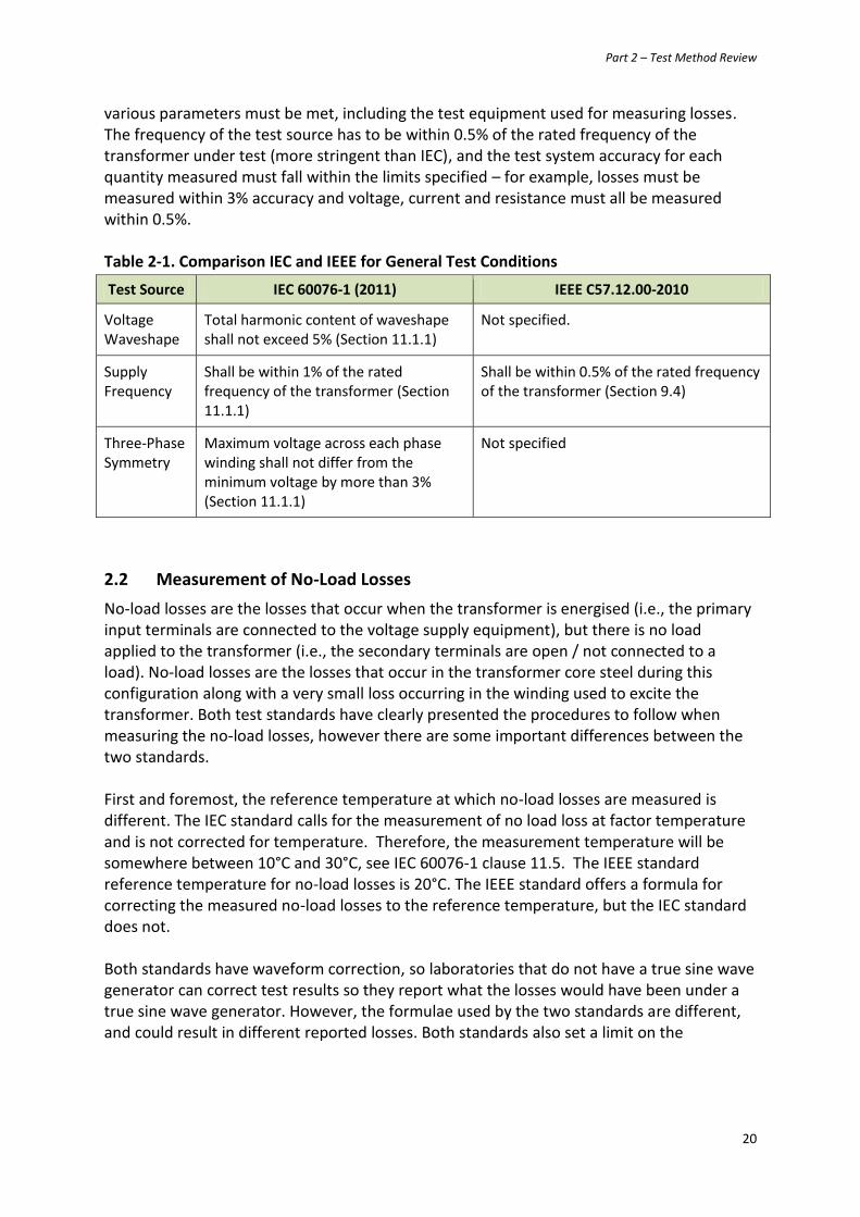
various parameters must be met, including the test equipment used for measuring losses. The frequency of the test source has to be within 0.5% of the rated frequency of the transformer under test (more stringent than IEC), and the test system accuracy for each quantity measured must fall within the limits specified – for example, losses must be measured within 3% accuracy and voltage, current and resistance must all be measured within 0.5%. Table 2-1. Comparison IEC and IEEE for General Test Conditions
Test Source IEC 60076-1 (2011) IEEE C57.12.00-2010
Voltage Waveshape
Total harmonic content of waveshape shall not exceed 5% (Section 11.1.1)
Not specified.
Supply Frequency
Shall be within 1% of the rated frequency of the transformer (Section 11.1.1)
Shall be within 0.5% of the rated frequency of the transformer (Section 9.4)
Three-Phase Symmetry
Maximum voltage across each phase winding shall not differ from the minimum voltage by more than 3% (Section 11.1.1)
Not specified
2.2 Measurement of No-Load Losses
No-load losses are the losses that occur when the transformer is energised (i.e., the primary input terminals are connected to the voltage supply equipment), but there is no load applied to the transformer (i.e., the secondary terminals are open / not connected to a load). No-load losses are the losses that occur in the transformer core steel during this configuration along with a very small loss occurring in the winding used to excite the transformer. Both test standards have clearly presented the procedures to follow when measuring the no-load losses, however there are some important differences between the two standards. First and foremost, the reference temperature at which no-load losses are measured is different. The IEC standard calls for the measurement of no load loss at factor temperature and is not corrected for temperature. Therefore, the measurement temperature will be somewhere between 10°C and 30°C, see IEC 60076-1 clause 11.5. The IEEE standard reference temperature for no-load losses is 20°C. The IEEE standard offers a formula for correcting the measured no-load losses to the reference temperature, but the IEC standard does not. Both standards have waveform correction, so laboratories that do not have a true sine wave generator can correct test results so they report what the losses would have been under a true sine wave generator. However, the formulae used by the two standards are different, and could result in different reported losses. Both standards also set a limit on the

Part 2 – Test Method Review
21
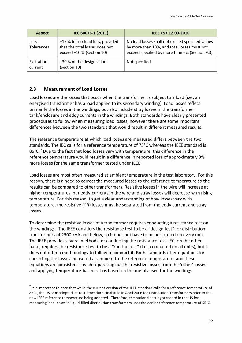
waveform correction that can be applied, however they describe those limits differently (see table below). The tolerances associated with the measurement of no-load losses differ between the two standards. IEC allows for slightly greater variance, up to +15% of the no-load loss (or load loss) as long as the variance of the total losses does not exceed more than +10 %.5 IEEE, on the other hand, states that the measured no load loss shall not exceed specified values by more than 10%, and total losses must not exceed the specified values by more than 6%. Thus, the IEEE tolerance is tighter than IEC. Finally, IEC establishes a maximum of +30% of the design value for the no-load current (i.e., excitation current) when making the no-load loss measurement. IEEE does not specify a limit on this current. The table below presents these comparisons and gives the citations. Table 2-2. Comparison IEC and IEEE for Measurement of No-Load Losses
Aspect IEC 60076-1 (2011) IEEE C57.12.00-2010
Reference Temperature
Reference temperature is 75°C (section 11.1.1); IEC does not have an equation for correcting measured losses to this reference temperature6
Core loss reference temperature is 20°C (section 5.9); offers an equation to correct measured losses to this reference temperature. IEEE C57.12.90 section 8.4 states that average oil temperature should be within 10% of the reference temperature (20°C), the difference between top and bottom oil temp shall not exceed 5°C and provides an equation for temperature correction.
Waveform Correction
Section 11.5 sets out an equation: P0 = Pm (1+d) where the measured no-load loss is Pm and d=(U’-U)/U’ where U is the measured average voltage and U’ is the measured r.m.s. voltage.
Pc (Tm) = Pm /(P1+kP2 ) k = (r.m.s. voltage / average voltage)2
Tm is average oil temp Pm is measured no-load loss P1 is per unit hysteresis loss and P2 is per unit eddy-current loss Pc is the waveform-corrected losses at Tm
(Section 8.3 of C57.12.90:2006)
Maximum Waveform Correction
The maximum difference between U’ and U shall be 3%. (Section 11.5)
The above equation should only be used where the correction is 5% or less. If greater than 5% then the voltage waveform for the measurement must be improved. (Section 8.3 of C57.12.90:2006)
5 The issue of the magnitude of these tolerances was discussed during the last revision of IEC 60076-1, and the
reason for them being so large is because of concern for some unusual transformer designs. It was noted that these tolerance values have not changed since before World War II. As a result, transformer specifiers have started incorporating “no positive tolerance clauses” into their contracts to ensure they receive a unit with the loss levels they expect. 6 The IEC standard takes a clear position against temperature correction for no-load losses, stating in section
11.5: “The no load losses shall not be corrected for any effect of temperature.”
Part 2 – Test Method Review
22
Aspect IEC 60076-1 (2011) IEEE C57.12.00-2010
Loss Tolerances
+15 % for no-load loss, provided that the total losses does not exceed +10 % (section 10)
No load losses shall not exceed specified values by more than 10%, and total losses must not exceed specified by more than 6% (Section 9.3)
Excitation current
+30 % of the design value (section 10)
Not specified.
2.3 Measurement of Load Losses
Load losses are the losses that occur when the transformer is subject to a load (i.e., an energised transformer has a load applied to its secondary winding). Load losses reflect primarily the losses in the windings, but also include stray losses in the transformer tank/enclosure and eddy currents in the windings. Both standards have clearly presented procedures to follow when measuring load losses, however there are some important differences between the two standards that would result in different measured results. The reference temperature at which load losses are measured differs between the two standards. The IEC calls for a reference temperature of 75°C whereas the IEEE standard is 85°C. 7 Due to the fact that load losses vary with temperature, this difference in the reference temperature would result in a difference in reported loss of approximately 3% more losses for the same transformer tested under IEEE. Load losses are most often measured at ambient temperature in the test laboratory. For this reason, there is a need to correct the measured losses to the reference temperature so the results can be compared to other transformers. Resistive losses in the wire will increase at higher temperatures, but eddy-currents in the wire and stray losses will decrease with rising temperature. For this reason, to get a clear understanding of how losses vary with temperature, the resistive (i2R) losses must be separated from the eddy current and stray losses. To determine the resistive losses of a transformer requires conducting a resistance test on the windings. The IEEE considers the resistance test to be a “design test” for distribution transformers of 2500 kVA and below, so it does not have to be performed on every unit. The IEEE provides several methods for conducting the resistance test. IEC, on the other hand, requires the resistance test to be a “routine test” (i.e., conducted on all units), but it does not offer a methodology to follow to conduct it. Both standards offer equations for correcting the losses measured at ambient to the reference temperature, and these equations are consistent – each separating out the resistive losses from the ‘other’ losses and applying temperature-based ratios based on the metals used for the windings.
7 It is important to note that while the current version of the IEEE standard calls for a reference temperature of
85°C, the US DOE adopted its Test Procedure Final Rule in April 2006 for Distribution Transformers prior to the new IEEE reference temperature being adopted. Therefore, the national testing standard in the US for measuring load losses in liquid-filled distribution transformers uses the earlier reference temperature of 55°C.

Part 2 – Test Method Review
23
The tolerances associated with the measurement of load losses differ between the two standards. IEC allows for slightly greater variance, up to +15% of the load loss (or no-load loss) as long as the variance of the total losses does not exceed more than +10 %. IEEE, on the other hand, has no limit for load loss measurement, except to say that the total losses (i.e., combined no-load and load losses) must not exceed the specified values by more than 6%. Thus, the IEEE tolerance is tighter than IEC. Finally, when measuring the load losses, the transformer should be tested at the rated current. However, some laboratories may not have the necessary equipment to maintain the rated current for the duration of the test, therefore the IEC permits the load losses to be measured at a lower level than the rated current. The minimum allowable test current for the load loss measurement in IEC is 50% of the rated capacity, to allow for measurement when very large rated powers or high impedances create problems with obtaining rated current in a test measurement. The IEEE does not specify whether partial current can be used when measuring load loss, therefore losses must always be measured at full load. Table 2-3. Comparison IEC and IEEE for Measurement Load Losses
Aspect IEC 60076-1 (2011) IEEE C57.12.00-2010
Reference Temperature
Reference temperature is 75°C (section 11.1.1); IEC has an equation for correcting to this temperature in Annex E (normative)
Load loss reference temperature is 85°C8 (section 5.9); and IEEE offers an equation to correct measured losses to this reference temperature (Section 9.4.2 of C57.12.90:2006)
Temperature Correction Equations
Where Pr is load loss corrected for temperature; I is the specified load current; Rr is the winding resistance at the reference temperature; and Par is the temperature corrected additional losses (see Annex E)
Where P(Tm) is the load loss at the reference temperature, Pr(Tm) is the calculated I2R loss at the reference temperature and Ps(Tm) is the calculated stray loss at the reference temperature (see Section 9.4.2 of C57.12.90:2006)
Loss Tolerances
+15 % for load loss, provided that the total losses does not exceed +10 % (section 10)
No limit for load loss measurement, but total losses must not exceed specified by more than 6% (Section 9.3)
Test Current Allows less than full-rated current to be used for load loss measurement, down to a minimum of 50% of the rated current (section 11.4). Direct current must be used for the measurement (Section 11.2.1)
Does not specify whether partial current can be used when measuring load loss. Various methods are offered for measuring
8 Please note that the current US DOE Test Procedure for liquid-filled distribution transformers calls for a
reference temperature of 55°C, as per the previous version of the IEEE standard.

Part 2 – Test Method Review
24
Aspect IEC 60076-1 (2011) IEEE C57.12.00-2010
Resistance Measurement Method
No methodology specified. Bridge method or Voltmeter-ammeter method (Section 5.3 of C57.12.90:2006)
Winding Temperature Guidelines
Cold resistance after 3 hour minimum with no excitation. Temperature rise. When determining temperature rise, the difference between top and bottom liquid shall not exceed 5 degrees, and a pump may be used (Section 11.2.3)
No excitation and no current in the windings from 3 to 8 hours depending on size of transformer. The top & bottom temperature difference shall not exceed 5 degrees (Section 5.1.2 of C57.12.90:2006)
On the issue of load-loss, it should be noted that the US DOE Test Procedure Final Rule was adopted in April 2006 and was based on an earlier draft of the IEEE test standard, which used 55°C as the reference temperature for the measurement of load losses in liquid-filled distribution transformers. This can be seen in the following excerpt from the US DOE Test Procedure9:
Figure 2-1. Excerpt from US DOE Test Procedure for Distribution Transformers
Here, the reference temperature for the load losses on dry-type are aligned with IEC (both are 75°C); however for the liquid-filled, 55°C must be corrected to 75°C for comparison with the other regulatory requirements. The method used to develop a temperature correction factor for the load losses is presented in Annex section A.4 of the Part 1 report in this series.
9 http://www.gpo.gov/fdsys/pkg/CFR-2012-title10-vol3/pdf/CFR-2012-title10-vol3-part431-subpartK-appA.pdf

Part 2 – Test Method Review
25
3 Achieving a Globally Harmonised Test Standard
The majority of the economies with regulatory and voluntary programmes for distribution transformers use IEC 60076 as the basis for their testing standards. The US and Canadian test standards are based on IEEE C57.12.00 and NEMA TP-2, which the previous chapter compared to the IEC standard. This comparison found differences in the methodologies followed for measuring no-load and load losses between the IEC and IEEE standards. Due to these differences, direct comparisons between models measured with these two standards are difficult. However, these two standards each have been used for many years, therefore manufacturers and their customers have come to expect and rely on the test methods with which they are most familiar. For this reason, it may be difficult to fully harmonise all aspects of these two regulations, however harmonisation should be maintained as a long-term objective. And each standards setting body (IEC and IEEE) has recognised this challenge and together created a “Dual Logo” single standard project to harmonise the different families of standards.10 This cooperative standards harmonisation effort applies to many product groups, including motors, instrumentation, nuclear power, transformers and more. To date, the following standards for transformers have been agreed through the “Dual Logo” process (however neither of these standards apply to distribution transformers):
IEC 60076-21 Ed. 1 (2011-12) (IEEE Std C57.15™-2009 Power Transformers - Part 21: Standard Requirements, Terminology, and Test Code for Step-Voltage Regulators
IEC 62032 Ed.1 (2005-03) (IEEE C57.135™-2001): Guide for the Application, Specification and Testing of Phase-Shifting Transformer
The SEAD countries can continue to work through their representatives participating in these two standardisation bodies – IEC and IEEE – and lend support to this “Dual Logo” programme. Additional support could further encourage and expand the work of the committees, to eventually achieve true global harmonisation of testing for distribution transformers. The following sections in this chapter address other differences that were encountered in this review, namely the best metric by which to define distribution transformer performance, the equation for calculating efficiency, the importance of the loading point and measurement accuracy.
3.1 Efficiency or Maximum Losses
The test standards or the regulatory documents provide a means to calculate the energy performance metric that is used to determine whether a particular transformer meets the requirements. Some economies establish maximum watts of loss that can occur at full load
10
Information about this collaboration, including documents that outline the co-operation and licencing agreements, the procedures followed and the joint development agreement itself can be found at the following website: http://standards.ieee.org/develop/intl/iec.html

Part 2 – Test Method Review
26
or at specific loading points, while other economies establish minimum efficiency requirements, which also require specification of a particular loading point (because load losses vary with loading). This section of the report discusses these two approaches and the advantages and disadvantages of each. In China, the European Union and other economies around the world, distribution transformer requirements are based on a set of maximum no-load and load-losses. These loss sets are two numerical requirements that must both be met for each compliant design. Once these two values are set, the design for the transformer becomes generally fixed, with certain materials and construction approaches favoured. The relationship between the two values of no-load and load-losses also establishes an implied, optimal loading point, according to the following relationship:
(
)
This relationship states that the optimal loading point (i.e., ‘peak efficiency’) for a given set of loss values occurs at the square-root of the ratio of the no-load losses to the load losses. Consider, as an example, the following set of maximum losses from China’s Grade 3 MEPS for three-phase liquid-filled transformers. The implied loading point of these maximum losses is given in the table below, where it is shown for these kVA ratings to vary from about 41% to 36% as the kVA values increase. And the implied loading point decreases with Grade 2 and with Grade 1. Table 3-1. Sample of kVA Ratings for China’s Three-Phase Liquid-Immersed Grade 3 MEPS
kVA China GB20052-2013 Grade 3 MEPS
No Load Loss (W) Load Loss (W) Optimal Loading Point
30 100 600 40.8%
50 130 870 38.7%
63 150 1,040 38.0%
80 180 1,250 37.9%
100 200 1,500 36.5%
125 240 1,800 36.5%
160 280 2,200 35.7%
200 340 2,600 36.2%
250 400 3,050 36.2%

Part 2 – Test Method Review
27
Thus, once individual loss sets are defined – no-load and load-losses - certain materials and construction approaches are favoured, and the requirement cannot be considered technologically neutral. This approach creates one design with an optimal loading point that is defined by the square-root of the ratio of the losses. If the transformer is operated beyond the optimum point, energy consumption of that transformer will be high, defeating the purpose of setting the MEPS in the first place. For this reason, the Team did not select this approach of maximum losses because it limits variety in the market, restricts the design and material options available to manufacturers, and results in utilities purchasing transformers that may have loading points that are not optimised for a particular installation or a customer’s requirements. In Australia, the United States and elsewhere, the regulator has decided to use ‘efficiency’ as the regulatory metric. Efficiency is a single numerical requirement that combines the no-load and load loss values together, and compares their relative magnitude to the power throughput of the transformer. Efficiency is a unit-less variable calculated by dividing power out by power in. The advantage to using efficiency instead of maximum losses is that it allows for more flexibility in the design of the transformer and the materials used in manufacturing the transformer. It allows a designer to trade-off core and coil losses, and allows manufacturers to still produce an optimised transformer for a customer. That said, efficiency also has a draw-back in that it must be defined at a particular loading point, and there is some uncertainty around the selection of that loading point. In this study, since most economies that use percentage efficiency are using 50% loading, this is the level selected for the recommendations in the Part 3 report. Finally, it should be noted that an alternative to having percentage efficiency would be to use maximum total loss, in which the regulator defines maximum losses as a sum of the no-load and load losses. This is the approach followed by Japan in the Top-Runner scheme. This approach still allows transformer manufacturers to trade-off core and coil losses in their compliant designs, enabling the overall reduction of losses in the transformer, just as they can do with percentage efficiency. This approach has all the advantages as the efficiency approach in terms of flexibility and customer-focus, and works with a regulatory metric that is both clear and broadly understood in the industry. However the point at which total loss is reported must be defined – for Japan it is at 40% loading for transformers at or below 500kVA and 50% loading for those greater than 500kVA.
3.2 Defining Efficiency
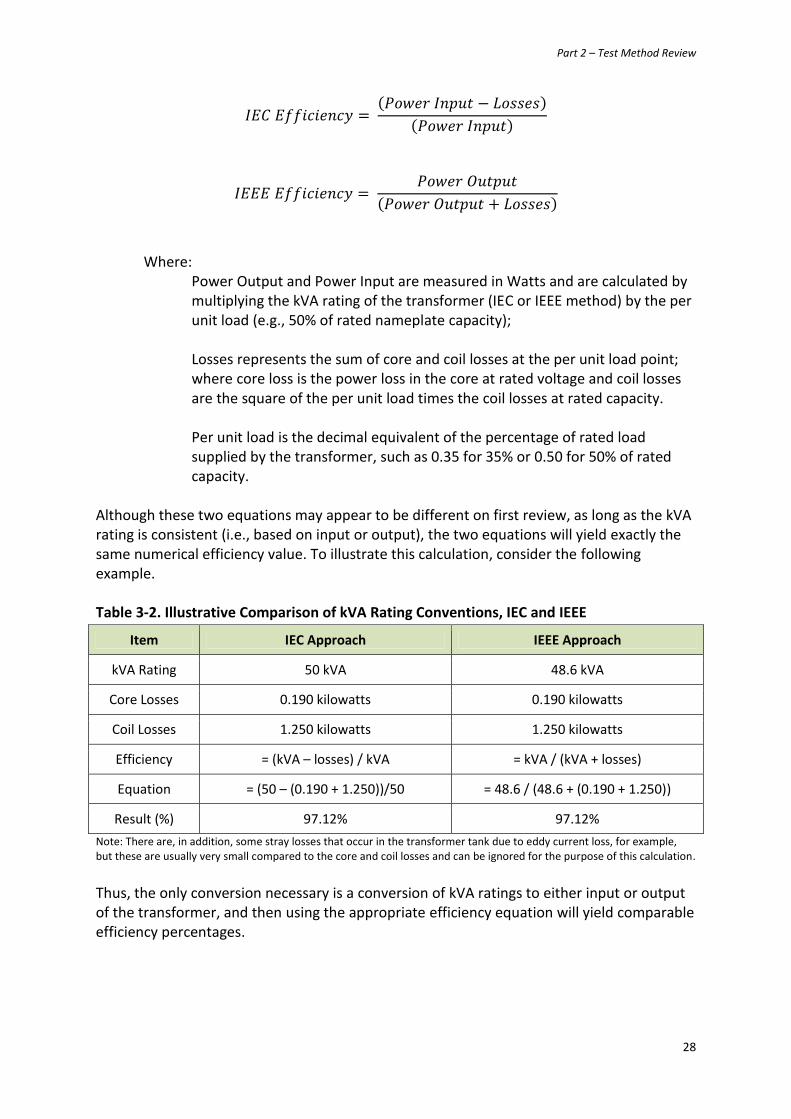
Efficiency is, broadly speaking, a measurement of power out divided by power in. However, the way that efficiency is calculated differs slightly between IEC and IEEE. This difference stems primarily from a difference in how transformers are rated – that is, the power capacity of a transformer. In IEC, the equation is based on the input power while for the IEEE, the equation is based on output power, as shown in the following equations:
Part 2 – Test Method Review
28
Where: Power Output and Power Input are measured in Watts and are calculated by multiplying the kVA rating of the transformer (IEC or IEEE method) by the per unit load (e.g., 50% of rated nameplate capacity); Losses represents the sum of core and coil losses at the per unit load point; where core loss is the power loss in the core at rated voltage and coil losses are the square of the per unit load times the coil losses at rated capacity. Per unit load is the decimal equivalent of the percentage of rated load supplied by the transformer, such as 0.35 for 35% or 0.50 for 50% of rated capacity.
Although these two equations may appear to be different on first review, as long as the kVA rating is consistent (i.e., based on input or output), the two equations will yield exactly the same numerical efficiency value. To illustrate this calculation, consider the following example. Table 3-2. Illustrative Comparison of kVA Rating Conventions, IEC and IEEE
Item IEC Approach IEEE Approach
kVA Rating 50 kVA 48.6 kVA
Core Losses 0.190 kilowatts 0.190 kilowatts
Coil Losses 1.250 kilowatts 1.250 kilowatts
Efficiency = (kVA – losses) / kVA = kVA / (kVA + losses)
Equation = (50 – (0.190 + 1.250))/50 = 48.6 / (48.6 + (0.190 + 1.250))
Result (%) 97.12% 97.12%
Note: There are, in addition, some stray losses that occur in the transformer tank due to eddy current loss, for example, but these are usually very small compared to the core and coil losses and can be ignored for the purpose of this calculation.
Thus, the only conversion necessary is a conversion of kVA ratings to either input or output of the transformer, and then using the appropriate efficiency equation will yield comparable efficiency percentages.
Part 2 – Test Method Review
29
As noted in Chapter 2 of this report, there is a difference in loss tolerance, whereas section 10 of IEC 60076-1 states that individual variance on core and coil measurements can be up to +15% greater in the population of transformers, provided that the total loss in the population does not exceed +10%.11 IEEE C57.12.00 has a more stringent requirement on the no-load loss measurement, which must not exceed +10% and a more stringent requirement that total loss in the population should be more than +6% of the sample (see section 9.3). IEEE does not take a position on the tolerance of the coil loss measurement. These requirements are not primarily about measurement accuracy of the test method. Rather, they state the model rejection threshold for a particular design, taking into account manufacturing and measurement uncertainty. The IEC provides more tolerance than IEEE considers necessary, however in an energy-efficiency programme, it would be up to the programme managers to determine the level of acceptable loss tolerance, if any.
3.3 Selecting a Loading Point
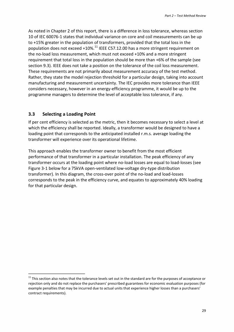
If per cent efficiency is selected as the metric, then it becomes necessary to select a level at which the efficiency shall be reported. Ideally, a transformer would be designed to have a loading point that corresponds to the anticipated installed r.m.s. average loading the transformer will experience over its operational lifetime. This approach enables the transformer owner to benefit from the most efficient performance of that transformer in a particular installation. The peak efficiency of any transformer occurs at the loading point where no-load losses are equal to load-losses (see Figure 3-1 below for a 75kVA open-ventilated low-voltage dry-type distribution transformer). In this diagram, the cross-over point of the no-load and load-losses corresponds to the peak in the efficiency curve, and equates to approximately 40% loading for that particular design.
11
This section also notes that the tolerance levels set out in the standard are for the purposes of acceptance or rejection only and do not replace the purchasers’ prescribed guarantees for economic evaluation purposes (for example penalties that may be incurred due to actual units that experience higher losses than a purchasers’ contract requirements).

Part 2 – Test Method Review
30
Figure 3-1. Efficiency Changes with Loading, Reaches Peak where NL = LL
The country review of energy-efficiency policies and programmes found a large variety of energy-efficiency requirements, including maximum watts of loss and per cent efficiency. The majority of countries reviewed required efficiency, and it was found that most often the loading associated with this efficiency requirement was set at 50% of the rated nameplate capacity of the transformer. This was the loading point selected for the suggested efficiency equations.
3.4 Measurement Accuracy
The accuracy of power loss measurements and the impact on the uncertainty of the power efficiency metric is calculated by the three different methods. Most MEPS tables specify power efficiencies to one hundredth of a per cent (i.e., 0.01%). Thus the power measurements, the resistance measurements and the temperature determinations must be made with sufficient accuracy to enable power efficiencies to be determined with accuracy to 0.01%. This means that the test uncertainty should ideally be +/-0.01% or preferably lower. For example, if the MEPS table says that 98.95% is the minimum limit for a particular rating then the measurement uncertainty must be sufficient to be able to distinguish between 98.95% and 98.94%. If a particular test standard gives a result of 98.93%, this would be a ‘fail’, however if the measurement uncertainty is actually +/- 0.02% then it would be a pass because 98.95% is within the allowable band given the uncertainty. For this reason it is necessary in the determination of power efficiency to state what the test method uncertainty is (as is required in almost all precision electrical determinations). Without such specification of uncertainty in the testing standard, specifying the regulatory requirements to levels of precision of 0.01 % is not really a viable approach.

Part 2 – Test Method Review
31
It is in this area that some deficiencies arise in the loss methods as outlined in IEC 60076. They are primarily specified just for core loss and copper loss compliance with a transformer type and the compliance is determined by a rather generous 2 or 3% compliance allowance. It is unlikely that an accuracy required for such a variation in allowable loss for general compliance purposes would be able to measure efficiency uncertainties down to +/-0.01% or lower. The DOE and the NEMA TP2 test standards offer more stringency on their measurement methods when compared to IEC because they are written specifically for measuring losses from distribution transformers with enough accuracy to determine power efficiency to the required level. One option to resolve this difference would be to consider some tightening of the tolerances associated with the IEC 60076 loss measurement methods to give improved accuracy that would be consistent with the required uncertainty levels in the policy documents. However, due to the wide diversity of transformer types covered under IEC 60076-1, a tightening of the tolerance levels could only be achieved in a practical way if the IEC were to establish a specific standard for distribution transformers, where the loss tolerances could be tailored to the distribution transformer market. In addition to this, it would also be helpful to require that testers report their uncertainties with their test results of efficiency. This would be helpful for policy makers to make an allowance for test results when determining compliance with MEPS specifications.


