PURCHASING DEPARTMENT 1772 County Services Parkway Marietta, Georgia 30008-4012 Mark Kohntopp (770) 528-8400/FAX (770) 528-1154 INTERIM DIRECTOR ADDENDUM No. 1 Sealed Bid # 12-5658 Mountain View Aquatic Center Air Quality Improvements and Interior Renovations Cobb County Parks, Recreation and Cultural Affairs Department DATE: April 2, 2012 Page 1 of 36 The following addendum hereby amends and/or modifies the Proposal Documents and specifications as originally issued for this project. All proposers are subject to the provisions of this Addendum. Include this original form inside your proposal package. Proposers shall acknowledge receipt of this addendum. This Addendum consists of: • Minutes from Pre-Bid Meeting held on March 27, 2012 • Clarifications to specifications • Questions submitted in writing to date • Sign In Sheet from the Pre-Bid Meeting All bids must be received before 12:00 (noon) by the Bid Opening date. Bids shall be delivered to Cobb County Purchasing Department, 1772 County Services Parkway, Marietta, GA 30008. Electronic / faxed bid response will not be considered. I acknowledge that I have received Addendum No. 1 Sealed Bid # 12-5658 Mountain View Aquatic Center Air Quality Improvements and Interior Renovations Cobb County Parks, Recreations and Cultural Affairs Department ____________________________________ Company Name Signature Date Sent to Purchasing ____ Please Print Name ______ Please sign, date, and return this form ONLY to: Cobb County Purchasing Department Fax #: 770-528-1154 E-Mail: [email protected]Please note: The deadline for questions is: April 3, 2012 by 5:00 pm Any questions received after this deadline will not be considered.
Transcript
PURCHASING DEPARTMENT 1772 County Services Parkway Marietta, Georgia 30008-4012 Mark Kohntopp (770) 528-8400/FAX (770) 528-1154 INTERIM DIRECTOR
ADDENDUM No. 1
Sealed Bid # 12-5658
Mountain View Aquatic Center Air Quality Improvements and Interior Renovations Cobb County Parks, Recreation and Cultural Affairs Department
DATE: April 2, 2012
Page 1 of 36 The following addendum hereby amends and/or modifies the Proposal Documents and specifications as originally issued for this project. All proposers are subject to the provisions of this Addendum.
Include this original form inside your proposal package. Proposers shall acknowledge receipt of this addendum.
This Addendum consists of:
• Minutes from Pre-Bid Meeting held on March 27, 2012 • Clarifications to specifications • Questions submitted in writing to date • Sign In Sheet from the Pre-Bid Meeting
All bids must be received before 12:00 (noon) by the Bid Opening date. Bids shall be delivered to Cobb County Purchasing Department, 1772 County Services Parkway, Marietta, GA 30008. Electronic / faxed bid response will not be considered. I acknowledge that I have received Addendum No. 1
Sealed Bid # 12-5658 Mountain View Aquatic Center Air Quality Improvements and Interior Renovations
Cobb County Parks, Recreations and Cultural Affairs Department
____________________________________ Company Name Signature Date Sent to Purchasing
____
Please Print Name ______
Please sign, date, and return this form ONLY to: Cobb County Purchasing Department
Mountain View Aquatic Center Air Quality Improvements and Interior Renovations A. Pre-Bid Meeting - March 27, 2012, 9:00 am, Mountain View Aquatic Center
1. General Project Notes Presented During the Meeting:
• General Scope – Pool (Natatorium) 1) New marcite finish in both pools (50 meter and instructional pools) 2) Ground main drain covers 3) Remove paint from curb around pools and apply clear sealer. 4) Remove, clean and replace existing gutter grating 5) Apply waterproofing material to inside of gutter 6) Saw cut critical areas in a diamond pattern to provide slip resistance 7) Refurbish the bulkhead at the 50 meter pool. 8) Repaint all existing painted surfaces. Rusted areas require primer per
specifications. 9) New return duct, painted. 10) Replace lane markers 11) Pressure wash and clean entire pool deck.
• General Scope – Mechanical
1) Replace existing PoolPak units. New dehumidifiers are being purchased from Seresco by the County. Contractor responsible for everything else associated with the delivery and installation except ordering the units and paying for them.
2) Install Paddock Bench Evacuators on pool deck in locations shown. Evacuators are being purchased from Paddock by the County. Contractor is responsible for everything else associated with the delivery and installation except ordering and paying for them. A Purchase Order has been issued for both the Seresco and Paddock units.
3) Mechanical demolition including removal of three boilers. 4) Install new boiler, heat exchangers, pumps, piping and all other work on the
drawings. 5) New dehumidifiers to provide heated pool water and preheat for the remainder
of the facility. Piping arrangement is shown on the drawings. 6) Electrical demolition and new work associated with new systems. 7) New duct work and exhaust fans
• General Information
1) As built drawings A1.1, A1.2 and P5.1 provided as part of the bid package are for reference only. Scale is not correct on these drawings. Field verify existing conditions as needed during bidding process.
2) If bidder prints drawings from the Purchasing website, bidder is responsible for confirming that the drawings are printed to the correct scale. The Owner
Sealed Bid # 12-5658 – Addendum #1 Page 3 of 36
will not be responsible for incorrect information (take offs, quantities, etc.) due to drawings being printed improperly from the website.
3) Qualification forms are included for General Contractor, Mechanical Subcontractor, Plumbing Subcontractor, Electrical Subcontractor and Pool Subcontractor. Qualification information must be submitted with the bid.
4) The schedule for the project is critical due to activities scheduled for the facility after the scheduled completion date. Contractor shall have access to the building July 11, 2012. Project must be substantially complete and functional by October 8 and final completion must be by October 15, 2012. Failure to complete on time is not an option and liquidated damages defined in the bid documents will be assessed if project is not completed as scheduled.
5) The $10,000.00 allowance on the bid form is for changes and additions to the work and not to be used at the discretion of the Contractor. Any additional costs must be submitted and approved, through the change order procedure, to be used against the allowance.
6) The scope of work discussed at the preconstruction meeting is very general. Refer to the plans and specifications for additional information. Any work defined in the plans, but not in the specifications or in the specifications and not on the plans is to be treated as if it is included in both and shall be included in the bid price.
7) All questions must be submitted in writing to Cobb County Purchasing at [email protected]
• Alternates – Refer to the specifications for specific information
1) Alternate #1 – Painting in areas outside the natatorium 2) Alternate #2 – Replace existing toilet partitions and urinal screens in both
restrooms. 3) Alternate #3 – Replace wall and floor tile grout in all tiled areas 4) Alternate #4 – Replace carpet and install new base in offices and staff areas
behind the front counter. 5) Alternate #5 – Replace the front counter 6) Alternate #6 – Paint the front canopy 7) Alternate #7 – Replace the 3 filters for the 50 meter pool with one specified
filter (design /build). 8) Alternate #8 – Replace the filter for the instructional pool with specified filter
(design/build).
• Questions and Clarifications from prebid conference 1) What is the budget? Answer
2) On the filter alternates, is there a modification to the electrical subpanel on the electrical drawings?
: It will be provided in the addendum. The construction budget for the project is in the range of $625,000 to $725,000. The cost of the Seresco dehumidifiers, Paddock Evacuators, design fees and program management fees are in addition to the $625,000 to $725,000 range. The County reserves the right to adjust the budget, up or down, as deemed appropriate by the County for the project.
design/build scope, including any electrical work associated with the filter replacement.
3) When is the cut off for questions? Answer4) The County plans to salvage some controls on the existing PoolPak units
prior to demolition.
: April 3, 2012 at 5:00 PM.
5) The existing concrete pads are to be used for the new dehumidification units. Note, they will have to be expanded and modified as necessary to accommodate the new units and associated piping.
6) What kind of glycol is to be used in the dry coolers? Answer
7) Are we to remove the grout at the pool curb?
: Propylene glycol.
Answer
8) Are we to replace the storage reels with the lane line markers?
: replace or repair broken or loose caulking at the curb.
Answer9) A walk-behind mini-groover may be used to cut the ½ inch diamond slip
resistant pattern.
: No
10) Will facility be completely closed to the public during construction? Answer
11) When complete all gutter grates must look like new. There are examples of new recently replaced grate sections currently in the gutter.
: Yes
12) Do we need to replace corroded wiring at the bulkhead? Answer
13) When complete, the bulkhead surface must be non-slip, similar to existing surface.
: No. Bulkhead wiring may be removed.
14) Does the contract include painting in storage areas at north end of building? Answer
15) The new grout in the locker room floor and cove will be grey in color. : No.
16) Will we replace the grout in the blue tile in the locker room walls? Answer
17) During the walk through, it was incorrectly stated that all ballasts in the light fixtures in the natatorium are to be replaced. Per specification section 26 51 00, the Contractor shall clean, re-lamp and repair all fixtures in Natatorium 129. Provide new ballasts where required to make the fixtures operational.
: Under Alternate #3, the wall tile and grout will be cleaned and the grout replaced only as necessary, primarily in the men’s and women’s shower areas. Replace all floor tile grout in the areas specified under Alternate #3. This shall include the replacement of the grout in the tile base in these areas.
B. Project Manual
1. Table of Contents – The table of contents lists section 23 0502 Miscellaneous HVAC Equipment as a section in Division 23 Mechanical. This section was not included and is not a part of the bid documents. Eliminate the reference to Section 23 0502 in the table of contents.
2. Section 01015 – Paragraph 1.02.4.b currently reads “b. Dismantle panels, hydroblast and re-surface per manufacturer’s (Neptune Benson) recommendations.” Eliminate that paragraph and replace it with the following “b. Dismantle deck and side panels, prepare painted surfaces to be resurfaced per manufacturer’s (Neptune Benson) recommendations. Switch swimming target marker panels to replace untargeted panels
Sealed Bid # 12-5658 – Addendum #1 Page 5 of 36
on opposite side of bulkhead. Resurface targets on untargeted panels and replace on competition side of pool. Resurface existing targeted panels to plain solid color panels matching existing and reinstall on bulkhead side opposite the competition side of the bulkhead. Prepare the deck panels and resurface per manufacturer’s (Neptune Benson) recommendations. (See section13000 Pool Work for additional information).”
3. Section 13000 – Miscellaneous Pool and Pool Related Work a. Pages 13000-8 through 13000-15 did not print properly in the printed version of the
specifications. The original version available at http://purchasing.cobbcountyga.gov/ is correct. To eliminate the discrepancy, a revised version of section 13000 is attached.
b. On page 13000-1, the approximate quantities provided for the total surface area for the pools is incorrect. Page 13000-1 of the attached revised version of Section 13000 has corrected approximate quantities for both pools. Bidders shall verify the quantities prior to bidding and prepare bids based on their own calculations.
c. Under “Refurbish Stainless Steel Bulkhead” on page 13000-2, the 3rd
paragraph reads: “Remove, prep and repaint all decking panels per manufacturer’s instructions. The paint material shall be Tnemec Epoxoline 66 two component epoxy. Colors to match existing panels.” This paragraph has been eliminated and replaced with the revised paragraphs in revised section 13000 attached.
4. Section 13150-B2 a. Delete paragraph 2.1.A and replace it with the following: “A. The filter system for the
instructional pool under this section shall be a Defender Model SP-27-48-487.” b. Delete paragraph 2.2.A and replace it with the following: “A. The filter system shall
have a capacity of filtering 110,000 gallons in 6 hours at a rate of 305 gallons per minute.”
c. Delete paragraph 2.2.B and replace it with the following; “B. The system shall consist of One Defender filter tank(s) with a total effective filter surface area of 381 square feet and shall operate at a rate consistent with the manufacturer’s recommended flow rate range (per minute per square foot of filter area) for the specified model number.
d. Delete paragraph 2.3.A and replace it with the following: “A. The filter tank shall not be less than 27” in diameter with a 60” side shell, suitable for 50 psi working pressure and hydrostatically tested to 75 psi. Tank shell shall be not less than ¼” thick. Bottom dished head shall be not less than ¼” thick. Top flat head shall be not less than 1 1/4” thick. All material shall be Type A-36 carbon steel.”
5. Section 23 2100 – MISCELLANEOUS HYDRONIC COMPONENTS. Delete this section in its entirety and replace it with the attached revised section 23 21000 – MISCELLANEOUS HYDRONIC COMPONENTS.
6. Section 23 3101 – Paddock Evacuators was not included in the project manual. Add attached section 23 3101 to the project manual.
a. The exhaust fan schedule on sheet M-5 indicates all exhaust fans will be by the Owner. The Owner will furnish exhaust fans 2 and 6 only. The Owner will also furnish exhaust fan curbs, variable frequency drive and 50 tubes of marine grade caulk. All other accessories required for the complete installation and operation of exhaust fans 2 and 6 shall be furnished and installed by the contractor. This includes all ducts shown on the drawings. Exhaust fans 3, 4 and 5 and all accessories, including duct, required for the complete installation and operation shall be furnished and installed by the Contractor.
D. Clarifications 1. All bidders who print the mechanical and electrical plans from the Purchasing website are
responsible for ensuring that the plans are printed to scale. The Owner will not be responsible for any costs resulting from drawings printed by the Contractor that are not to scale. As-Built Drawings A-1, A-2 and PF-5 (printed and electronic) are not to scale and shall not be scaled to determine dimensions.
2. Various sections of the project manual indicate that the Seresco dehumidification units will be delivered in August. The units are scheduled to be delivered no later than August 1. The manufacturer may make the units available for delivery as early as mid July. The contractor shall coordinate the exact delivery date of the units with the manufacturer and be prepared to handle the units as specified and required upon arrival at the site.
3. See attached drawing ESK-1 for clarifications concerning electrical outlets at exhaust fans 3 & 4.
4. See attached drawing MSK-1 for additional information concerning flue through the roof detail.
5. See attached drawing MSK-2 showing an elevation and/or sections for evacuator benches and exhaust fans EF-2, EF-3 and EF-4.
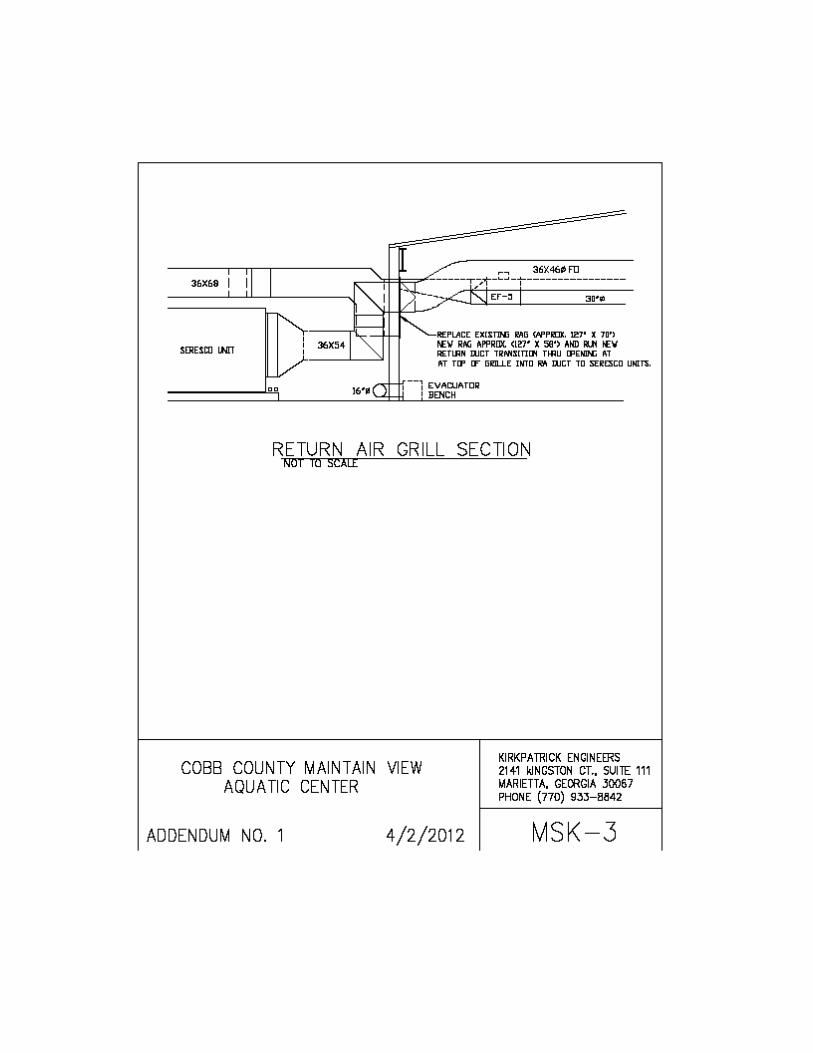
6. See attached drawing MSK-3 for a return air grill section near the Seresco units.
E. Questions submitted in writing to date: Question: During the prebid meeting yesterday, we were told to clean the gutter grating to remove stains or replace badly stained pieces if they did not come clean. The manufacturer is Lawson Aquatics (formerly known as Grate Technologies). They informed us that the "pattern" on their current grating is slightly different than the grating that was installed when the pools were originally built. If the grating that is replaced does not match the existing grating, will the owner be OK with that or do they want all the grating replaced? Answer: The pattern on the grating may be slightly different than the pattern on the existing grating if the existing pattern is not available. Provide a product data submittal and a sample of the proposed grating for review by the Owner prior to ordering the material.
Sealed Bid # 12-5658 – Addendum #1 Page 7 of 36
Question: Alternate 7 and 8 are for filter replacements for the two pools. The specs for the instructional pool filter replacement (Alt 8) and the 50 meter pool (Alt 7) list the same filter and capacity. Can the owner provide the corrected model number for the filter for the instructional pool please? Answer:
The revised model number can be found in the revisions to paragraph 4 in “B. Project Manual” above.
Remove and/or scarify existing marcite surface of 50 meter and instructional pool to prepare for marcite (white Portland and Pool Mix marble) resurfacing. Approximate total surface area: 50 meter pool 15,700 sq.ft. ; Instructional Pool 4,400 sq.ft. Bidders shall verify quantity prior to bidding.
• Remove and reinstall existing defective tile, install matching tiles. Matching tiles believed to be Dal-Tile Mosaic tile.
• Cut out any metal fasteners and/or rebar causing rust stain at a minimum depth of 1” below concrete surface and patch area with hydraulic cement
• Scarify the pool surface and prep for adhesive Saw cut around main drains, returns and tile providing a 1” – 2” true saw cut to taper marcite transition to the same. Apply Kover Krete Pre-Kote System or equal product acceptable to County. See attached product data sheet for product information and application guidelines. Refer to www.koverkrete.com for additional information. Before plastering pool a representative from the County and Pool Company will inspect and sign off on all
prep work Apply white plaster mix (minimum 3/8” thick) and trowel to a smooth finish. Plaster mix will be a 3 to 5 ratio,
Portland to pool mix marble. Other pool related work:
• Ground stainless steel main drain covers (6) to pool rebar framework. Attach underground rated
lug to rebar and connect copper ground wire to lug on drain cover frame to rebar lug as required by the drain cover manufacturer. Completely encase rebar connection and ground wire in hydraulic cement and finish with marcite.
• Completely remove paint off of concrete curbing around the perimeter of pools with a high pressure
washer. Remove all paint to substrate without damaging the concrete surface. Seal concrete curb with a clear slip resistant concrete sealer, Sherwin Williams H&C Concrete Sealer Wet Look with Shark Grip ™ or approved equivalent. Contractor shall seal a ten ft. long section of curb for review and approval by the Owner prior to proceeding with the work.
• Remove gutter grating around the perimeter for both pools and clean interior gutter surface with
TSP (Trisodium Phosphate), rinse thoroughly and apply muriatic acid in water 1:5 ratio solution and pressure wash as to receive BASF “Thoroseal” Waterproof cement-based coating mixed with BASF Acryl 60 Water-based acrylic bonding and modifying admixture per the manufacturer’s recommendation. Manufacturer’s recommendations and product data sheets are attached at the end of this section.
• Completely clean gutter grating stains and re-install; replace grates broken or damaged as a result
of the removal, cleaning, handling or any reason associated with the construction, with new grating material. If stains are not completely removed, replace with new grating material. New material to be equal to existing grating material. Manufacturer of grates, Grate Technology, was purchased by Neptune – Benson pool equipment manufacturer. The item is called “I – bar perpendicular”.
• Clean surge tanks surface with TSP, rinse thoroughly and use muriatic acid in water 1:5 ratio solution so to receive BASF “Thoroseal” Waterproof cement-based coating mixed with BASF Acryl60 Water-based acrylic bonding and modifying admixture per the manufacturer recommendation.
• Saw cut a ½” diamond shape pattern approximately ¼” deep by ¼” wide in the deck in locations
indicated by using a multi-blade track saw. This can be accomplished using a walk behind mini-groover saw manufactured by Diamond Products (or equivalent). Drawing showing locations of areas to b saw cut is included at the end of this specification section. Assume a quantity of 2039 square feet of surface area to be cut. An outline of each area shown shall be cut prior to cutting diamond shaped patterns.
• Refurbish Stainless Steel Bulkhead. Existing bulkhead was manufactured by Neptune-Benson.
Thoroughly visually inspect all bulkhead welds. Review proposed welds for Owner concurrence prior to proceeding with welding. Make appropriate repairs to welds as needed; assume that the project will require a certified welder (stainless tig) for a minimum of three days. Hydro-blast rust areas with a high pressure hydro blast washer (20,000 to 40,000 psi) to remove all rust. Clean all stainless with one of the following products (or equal): CitriSurf 77 Stainless Steel cleaner and passivation system; Nitric Acid (20%) solution. Please refer to MSDS requirements for handling of materials.
Coat exposed internal stainless with Bitumastic 300M Coal Epoxy or equivalent. See Link:
http://www.farwestcorrosion.com/ccp/protect/carbolin/bitumastic300M.htm Remove and/or prep and resurface all decking panels, targeted side panels and un-targeted
side panels per manufacturer’s instructions. The paint material shall be Tnemec Epoxoline 66 two component epoxy. Colors to match existing panels.
Dismantle panels, prepare painted surfaces to be resurfaced per manufacturer’s (Neptune
Benson) recommendations. Switch swimming target marker panels to replace untargeted panels on opposite side of bulkhead. Resurface untargeted solid side panels to be targeted panels to match existing and replace on competition side on pool. Resurface existing targeted panels to be plain solid panels matching color and reinstall on bulkhead side opposite the competition side of the bulkhead. Prepare the deck panels and resurface per manufacture’s (Neptune Benson) recommendations.
• Replace 10 – 50 meter lane lines with 6” Competitor/ Gold Medal brand lane lines with 10 - 25
yard disconnect sections. See attached specification for additional information. Refer to the product data sheet at the end of this specification and this link for additional information:
Minimum warranty on material and workmanship 1 year. Cobb County will maintain proper water chemistry for 30 days Cobb County will brush pool for approximately 2-3 weeks to ensure proper curing of new plaster.
Drawings and general provisions of the Contract, including General and Supplementary Conditions and Division-1 Specification sections, apply to work of this section.
1.2 WORK INCLUDED:
A. Provide all labor, materials, necessary equipment and services to complete hydronic systems as indicated on the drawings, as specified herein or both, except as for items specifically indicated as "NIC ITEMS".
1.3 REFERENCES:
ASTM, ANSI/ASME, and ASME standards and codes as specifically referred to under PART 2 PRODUCTS and PART 3 EXECUTION.
1.4 SUBMITTALS:
A. Shop Drawings and Product Data: Submit in accordance with Section 23 0500 and include manufacturer's installation instructions:
PART 2 - PRODUCTS 2.1 WATER PRESSURE REDUCING VALVE
A. Water pressure regulator shall be field adjustable, self contained, single seated, direct acting, spring loaded type with a diaphragm. Valve body and spring shall be bronze and all other parts shall have a corrosion resistance equal to bronze. All valves must be seated against leakage including a top cover over the adjusting screw.
2.2 THERMOMETERS:
A. Description: Liquid filled, 3-1/2" dial type, adjustable angle, accurate within one scale division. Stainless steel case construction with removable ring and plastic crystal cover. White dial face with black markings and red tipped adjustable pointer. Brass thermometer wells with 2" extension necks for installation in threaded openings with screwed well caps chained to each well.
B. Ranges: Manufacturer's standard comparable to:
Hot Water: 30 to 300 degrees F
23 2100 -3
C. Thermometer Test Wells: Brass wells as specified in A above designed to
accept either dial thermometer or test thermometer.
D. Provide equal products by Ashcroft, Dwyer, Omega
2.3 PRESSURE GAUGES:
A. Description: Bourdon tube type with bronze bushed, stainless steel movement, stainless steel case less back flange, pressed steel rings, 1% accuracy, 3-1/2" white dial with black lines and figures, and adjustable pointer.
C. Accessories: Brass needle valve gauge cocks (Trerice #735-2).
D. Provide equal products by Ashcroft, Dwyer, Omega
2.4 FLEXIBLE PIPE CONNECTIONS:
A. Description: Spool type rubber connectors designed for flanged connections and used on water service.
B. Connectors of concentric spool type with not less than 1 arch and designed to be
secured between two pipe flanges. Leak proof lining smooth and unaffected by fluid. Fabric and rubber body with metal reinforcement. Neoprene cover with manufacturer's name and model displayed. Provide metal retaining rings and control rods. In addition comply with requirements of Section 15140 with that section taking precedence in case of conflict.
C. Minimum Service Requirements:
Pipe Size Working Pressure Temperature
thru 4" 150 PSIG 250 degrees F 5" thru 12" 125 PSIG 250 degrees F
2.5 COMBINATION TEMPERATURE AND PRESSURE TEST PORTS
A. Provide test plugs with gasketed caps equal to Pete's Plug as manufactured by Peterson Equipment Company.
2.6 AUTOMATIC AIR ELIMINATOR
A. Maximum temperature operating range shall be 250 deg. F, air elimination range shall be 2 to 133 psi, Cast Iron body and cover, stainless steel control portion, carbon steel bolts and Vitron valve seat. Automatic air eliminator shall be equal to Armstrong Model AAE - 750.
2.7 VORTEX AIR SEPARATOR
A. Furnish and install a (line sized) Vortex Air Separator as shown on the drawings. Unit shall be Armstrong Model VAS with system strainer with additional tap for air separator to facilitate blow down. Air separator shall be equipped with a system strainer with free area of not less than four times the cross sectional area of the connecting piping.
2.8 PRE-CHARGED VERTICAL EXPANSION TANK
A. Furnish and install an ArmstrongAX200V ASMEP Pre-Charged Diaphragm Expansion tank, stamped 125 psi working pressure. Tank shall be equipped with a heavy-duty butyl diaphragm. Tank shall be supplied with a ring base and NPT system connection and an air charging valve connection shall be provided to facilitate adjusting pressure to meet actual system conditions.
2.9 PUMP SUCTION GUIDES
A. Cast iron body with ANSI or PN16 flanges, stabilizing vanes to reduce turbulence and create optimum flow conditions. Strainer perforated stainless steel, star shaped for strength and designed to provide large flow area to reduce pressure drop. Armstrong Model SG or equal.
2.10 FLO-TREX VALVES
A. Furnish and install on the discharge of each primary pump an Armstrong Model FTV Flow-Trex Combination Valve. Each valve shall incorporate three functions: Tight shut-off, spring enclosure type silent non-slam check valve and effective throttling of flow measurement capability valve. Equal to Armstrong Model FTV Flo-Trex.
2.11 PLATE AND FRAME HEAT EXCHANGER
23 2100 -5
A. The Plate and Frame Heat Exchanger shall be designed, fabricated and tested in accordance with the requirements of Section VIII, Division 1 of the ASME code, and shall be code stamped for 125 psig design pressure.
B. Plates shall be 316 stainless steel and gaskets shall be Nitril Rubber, one piece
construction.
C. Units shall be sized for capacities as shown on drawings and shall be equal to Sondex A/S PHE, Alpha Lavel, Mueller, ACCU-THERM.
2.12 GLASS LINED STORAGE TANK WITH HEAT EXCHANGER
A. Provide Insulated 80 gallon, glass lined storage tank with a single stainless steel, Cupronickel or copper coil heat exchanger located in lower part of tank without electric backup heater. Unit shall be designed for domestic hot water storage. Provide T&P valve. Heat-Flo Products, HTP, Laars, A.O. Smith, State Industries or approved equal.
PART 3 - EXECUTION 3.1 PIPE INSTALLATION:
A. General: Be responsible for fitting of materials and equipment, perform all dimensional layout of work and establish lines and grades. Install pipe lines to conform to conditions encountered, off-setting to clear structural members and ducts. Coupled short sections of pipe, bushings, close nipples, long screws, bullhead tees, and crosses prohibited. Install without springing or forcing, and clear windows, doors and other openings. Cutting or other weakening of building structure to facilitate piping installation not permitted. Provide sufficient swing joints, anchors, expansion loops necessary to permit free expansion and contraction without causing undue stresses. Make changes in direction with fittings. Support piping independently at equipment so its weight not supported by equipment. Install vertical risers plumb and straight, horizontal lines parallel with walls and partitions. Conceal piping above ceilings and within furring, chases, or walls wherever possible.
B. Preparation: Remove scale, welding slag, dirt, or foreign material inside and
outside, before assembly. Ream pipe and tube ends. Remove burrs. Bevel plain end ferrous pipe for welding.
C. Routes and Grades:
(1) Route piping in general locations indicated, in an orderly manner and to
maintain required grades. Coordinate with other piping, conduits, ducts and equipment and make necessary offsets to accommodate same. Install piping to conserve headroom and interfere as little as possible with use of available space. Group piping wherever possible at common
23 2100 -6
elevation. Install concealed pipes close to building structure to keep furring to minimum.
(2) Slope piping 1" in forty feet and arrange to drain at low points. Equip low points with drain valves except where underground. At high points where water flow turns down, provide collecting chambers and automatic air vents equipped with cut-off valve in connection line; air relief and drain line run to drain, service sink, plumbing vent stack, or to building exterior.
D. Supports and Expansion:
(1) Install pipe supports and hangers to provide piping systems which are
self-supporting and not dependent upon connection to equipment for support and stability. Refer to Section 23 2113.
(2) Install to permit free expansion and contraction, except where drawings specifically indicate an anchor or guide.
E. Buried Piping:
(1) Excavate and backfill in accordance with General Conditions
(2) Steel and copper pipe bedded on 4" minimum of clean sand and covered
with minimum of 6" of sand.
F. Automatic Control Devices: Install valves furnished under Fan Coil section and provide for insertion wells required for temperature sensing and thermometers.
G. Valves: Where indicated or specified, provide shut-off valves and unions or
flanges suitably located, to isolate each item of equipment, branch circuit or section of piping. Lug type butterfly valves do not require additional set of matched flanges.
H. Clearance: Provide clearance for proper installation of insulation and for access
to valves, air vents, drains, unions, etc. Provide minimum 1/2" clearance between pipes after insulation or application of escutcheons.
I. Size Changes:
(1) Make changes in pipe sizes for horizontal pipe lines with eccentric
reducing couplings, except that reducing tees and reducing elbows will be allowed for connections for pressure gauges and gauge cocks, for thermometers and test wells, and for pipe mounted insertion-type temperature control devices.
(2) In chilled water lines and space heating hot water lines install eccentric
reducing couplings with flat side on top to maintain top of pipe line flush and facilitate flow of air to automatic air vent locations. In condensate drain and other drain lines, install eccentric reducing couplings with flat
23 2100 -7
side on bottom to maintain bottom of pipe line flush and allow line to drain clear.
(3) Reducing tees, reducing elbows and concentric reducing couplings
allowed for changing pipe sizes in vertical risers and for making connections to equipment from vertical risers. In pump suction lines at horizontal pump connection, only eccentric reducing couplings allowed with flat side of coupling on top.
J. Elbows: Use long radius type for 2-1/2" and larger and at pump suction
connections.
K. Dissimilar Metals: Use dielectric unions, couplings, or insulating flanges with isolating bushings for bolts.
L. Connections:
(1) Screw join steel piping up to and including 2". Weld piping 2-1/2" and
larger including branch connections.
(2) For steel piping, factory fabricated forged steel shaped fittings may be used in lieu of welding tees if main is two pipe sizes or more larger than branch takeoff; shaped fittings shall be weldolets for branch sizes 2-1/2" and larger and threadolets for branch sizes 2" and smaller; branch takeoffs at 45 degrees to mains shall be made with factory fabricated latrolets.
(3) Use grooved mechanical couplings and mechanical fasteners only in
accessible locations.
(4) Make connections to equipment, control valves, and branch mains with unions, flanges or grooved mechanical couplings to allow disassembly of piping for removal and maintenance. Each coil, pump, and control valve to have one union or flange per pipe connection.
3.2 PIPE CONNECTIONS:
A. Welded Joints:
(1) Welding techniques and practices follow recommendations contained in Welding Handbook of American Welding Society, particularly Chapter 57, "Industrial Piping" and Code for Pressure Piping ANSI B31.
(2) Welding done by metal-arc welding process.
(3) Carbon steel welding rods conform to ASTM A233, Class E60 Series.
23 2100 -8
B. Screwed Joints: Cut threads accurately with axis of threads so that not more than 4 threads show beyond fitting. Joints made by applying non-toxic commercial grade, oil based pipe joint compound to male thread and then screwing tight into fitting. Teflon joint tape may be used as an alternate to joint compound.
C. Mechanical Joints for Grooved End Pipe and Fittings: Designed to mechanically
engage and lock grooved or shouldered pipe and fitting ends in positive couple and to allow for some degree of angular deflection and contraction-expansion. Each coupling consist of metal housing-clamps in 2 or more parts, a single C-shaped composition sealing gasket with internal sealing lips projecting diagonally inward so that internal pressure serves to increase tightness of seal, and bolted or pinned in place.
D. Sweat Joints: Solder joints in copper pipe made by first cleaning tube end and
socket in fitting with sand cloth and then by evenly applying heat to joint and using Sil Fos solder for sealing.
E. Flanged Joints: Flanged connections made up with gaskets, full face or ring type
to match flanges, properly tightened. 3.3 INSTALLATION OF FLEXIBLE PIPE CONNECTIONS:
A. Install in accordance with manufacturer's instructions. Align so that no stress is placed on control rods and that under normal operation, the control rods are loose.
B. Provide flexible connections for:
(1) Base Mounted Pumps.
(2) In-line Pumps 3.4 LEAK AND PRESSURE TESTS:
A. General: Be responsible for testing of piping systems. Maintain records of tests made and provide instruments required for testing. Defects in piping reworked, repaired, and retested until proven tight. Concealed work tested as partial system before being concealed or insulated. Insure that test pressure which might damage equipment does not reach such units by valving them off or otherwise isolating them during test. Keep field records and submit to Architect.
B. Water Piping for HVAC Water Systems: Subject to hydrostatic test of not less
than 100 PSIG for duration of 1 hour without loss of pressure with pressure source disconnected.
23 2100 -9
C. Drain Lines (including air conditioning condensate drain lines): Temporarily cap or plug and fill with water (before insulation is applied) and visually inspect for leaks.
3.5 CLEANING:
A. Clean and flush piping in accordance with Section 2302513–HVAC Water Treatment.
END OF SECTION
23 3101 - 1
SECTION 23 3101
PADDOCK EVACUATORS PART 1- GENERAL 1.01 DESCRIPTION
A. Paddock Evacuators shall be furnished by the Owner and installed by the Contractor.
• Poor air quality as result of high bather load creating high levels of off-gassing of Disinfectant by Products.
The Contractor shall coordinate delivery, inspect, receive, unload, protect and completely install the units including all ductwork, piping, electrical, etc. as required for a complete system. All necessary appurtenances such as materials, roof curbs, wall brackets, ductwork, anchors, controls, etc. shall be provided by the Contractor.
1.02 PADDOCK DESCRIPTION, SCOPE OF WORK AND SPECIFICATIONS MOUNTAIN VIEW AQUATIC CENTER DESIGN SOLUTION / SCOPE OF WORK Issue:
• When the production rate of off-gassing Disinfectant by Products (trichloramines) exceeds the mechanical systems ability to dilute them, bad air quality conditions develop.
Solution: The Paddock Evacuator design solution is based on source capturing the low hanging, heavy DBP laden air before it can be swept into the facilities mechanical system. The Evacuator equipment package has been purchased directly by Cobb County and the material will be turned over to the successful contactors for installation. The required duct work, hanger, mounting and accessories needed, and shown on the contract drawings will be supplied and installed by the Contractor.
Paddock Evacuator System: Location # Bench System Max. Design Exhaust System 1 South instructional pool
corner Duel Bench, 2 connection boxes
3200cfm
System 2 Middle of 50 meter Bench, 2 connection boxes 4400 cfm System 3 End of 50 meter Bench, 2 connection boxes 4400 cfm
Evacuator Bench Installation: o Install(3) independent Paddock Evacuator™ Bench systems as defined in the
Design Solution drawing:
23 3101 - 2
System 1 is a fiberglass bench system consisting of 8’ interlocking 16” x 16” molded benches with 8’ fiberglass bottoms, and (2) exhaust connection boxes which are leveled and secured to deck with stainless steel fasteners
System 2 is a fiberglass bench system consisting of 8’ interlocking 16” x 16” molded benches with 8’ fiberglass bottoms, and (2) exhaust connection boxes which are leveled and secured to deck with stainless steel fasteners.
System 3 is a fiberglass bench system consisting of 8’ interlocking 16” x 16” molded benches with 8’ fiberglass bottoms, and (2) exhaust connection boxes which are leveled and secured to deck with stainless steel fasteners
Exhaust Plenum Installation - supplied and installed by Contractor
o Install independent exhaust plenums from Evacuator Connection Box through side walls to exhaust system fans as defined on Design Solution Drawing and contract drawings. System 1 – install a 20” duct pipe from (2) Connection Boxes through side
wall to custom fan curb box connection point System 2 – install a 16” duct pipe from (2) Connection Boxes through side
wall to custom fan curb box connection point System 3 – install a 16” duct pipe from (2) Connection Boxes through side
wall to custom fan curb box connection point Exhaust Fans Installation
o Install Evacuator Exhaust Fan at designated location to include equipment pad and security barrier:
• System 1 – Secure Custom Curb Box to equipment pad. Connect PVC exhaust plenum to fan curb
• System 2 – Secure Custom Curb Box to equipment pad. Connect PVC exhaust plenum to fan curb
• System 3 – Secure Custom Curb Box to equipment pad. Connect PVC exhaust plenum to fan curb
• Electrical Connections by contractor o Needed power requirements , disconnects, switches ,and system control
locations Paddock Evacuator Company will provide the following thru the owner
• Paddock Evacuator Design Solution • Engineering support for final design and system balance (Contractor shall balance
systems) • Paddock Evacuator Equipment to include:
23 3101 - 3
o Paddock Evacuator Source Capture Bench System (3) Paddock Evacuator Bench Systems as described above (2) Exhaust Fans (EF-2 and EF-6) and custom mounting curb boxes
CONTRACTOR INSTALLATION RESPONSIBILITIES:
• Coordinating delivery, inspecting, accepting, unloading and protecting of materials identified to be purchased by the Owner
• Installation of evacuator system • Supply and install PVC duct materials, accessories, and concrete pad if required • Balance systems with facility mechanical system • Provide and install electrical service , connections, disconnects, and switches • Provide and install controls and integration with HVAC system • Evacuator should operate 24/7