36
SEALED PELLET STOVE AIKE COMFORT AIR 8 M1 PART 1 - REGULATIONS AND ASSEMBLY Instructions in English INSTALLATION GUIDE GB

SEALED PELLET STOVE
AIKE COMFORT AIR 8 M1PART 1 - REGULATIONS AND ASSEMBLY
Instructions in English
INSTALLATION GUIDE GB
II
TABLE OF CONTENTS
TABLE OF CONTENTS .................................................................................................. IIINTRODUCTION ..........................................................................................................11-WARNINGS AND WARRANTY CONDITIONS .................................................................22-INSTALLATION .........................................................................................................83-DRAWINGS AND TECHNICAL FEATURES ....................................................................174-UNPACKING ...........................................................................................................195-CLADDING REMOVAL ..............................................................................................226-DOOR OPENING .....................................................................................................257-CONNECTIONS TO ADDITIONAL DEVICES ..................................................................268-LOADING THE PELLETS ...........................................................................................30

1
INTRODUCTION
Technical Dept. - All rights reserved - Reproduction prohibited
Dear Customer, our products are designed and manufactured in compliance with European reference standards for construction products (EN13240 for wood-burning stoves, EN14785 for pellet-burning appliances, EN13229 for fireplaces/wood-burning inserts and EN 12815 for wood-burning range cookers), with high quality materials and extensive experience in transformation processes. The products also meet the essential requirements of Directive 2006/95/EC (Low Voltage) and Directive 2004/108/EC (Electromagnetic Compatibility).To get the best performance, we suggest you read the instructions in this manual carefully.This installation and use manual forms an integral part of the product: ensure that the manual is always supplied with the appliance, even if it changes owner. If the manual is lost, you can request another copy from the local Technical Department or download it directly from the company website.All local regulations, including those referring to national and European standards, must be observed when installing the appliance.In Italy, for the installation of systems with biomass below 35KW, refer to ministerial decree D.M. 37/08, and the qualified installation technician with the appropriate requisites must issue a certificate of compliance for the system installed. (By system we intend Stove+Flue+Air vent).
REVISIONS TO THE PUBLICATIONThe content of this manual is strictly technical and the property of MCZ Group Spa.No part of this manual may be translated into other languages, adapted or reproduced, even in part, in other mechanical or electronic forms, photocopies, recordings or other, without the prior written authorisation from MCZ Group Spa.The company reserves the right to make changes to the product at any time without prior notice. The proprietary company reserves its rights according to law.
CARE OF THE MANUAL AND HOW TO CONSULT IT• Take care of this manual and keep it in an easily and rapidly accessible place.• Should the manual be misplaced or ruined, request a copy from your Retailer or directly from the Manufacturer, specifying the
product identification data. You can also download it directly from the company website.• “Bold text” requires particular attention.• “Italicised text” is used to call your attention to other paragraphs in the manual or for any additional clarifications.• “NOTE” provides the reader with additional information.
SYMBOLS USED IN THE MANUAL
ATTENTION:Read the corresponding message with care because failure to observe the information provided could result in serious damage to the product and danger to the persons who use it.
INFORMATION:failure to comply with these provisions will compromise use of the product.
OPERATING SEQUENCES:sequence of buttons to be pressed to access the menus or change settings.
MANUALcarefully read this manual or the relative instructions.
2
1-WARNINGS AND WARRANTY CONDITIONS
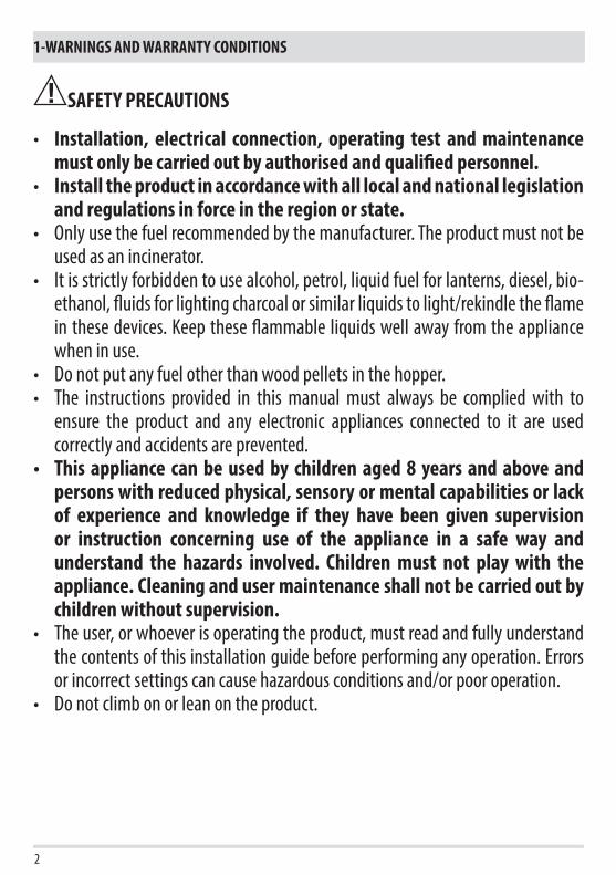
SAFETY PRECAUTIONS
• Installation, electrical connection, operating test and maintenance must only be carried out by authorised and qualified personnel.
• Install the product in accordance with all local and national legislation and regulations in force in the region or state.
• Only use the fuel recommended by the manufacturer. The product must not be used as an incinerator.
• It is strictly forbidden to use alcohol, petrol, liquid fuel for lanterns, diesel, bio-ethanol, fluids for lighting charcoal or similar liquids to light/rekindle the flame in these devices. Keep these flammable liquids well away from the appliance when in use.
• Do not put any fuel other than wood pellets in the hopper.• The instructions provided in this manual must always be complied with to
ensure the product and any electronic appliances connected to it are used correctly and accidents are prevented.
• This appliance can be used by children aged 8 years and above and persons with reduced physical, sensory or mental capabilities or lack of experience and knowledge if they have been given supervision or instruction concerning use of the appliance in a safe way and understand the hazards involved. Children must not play with the appliance. Cleaning and user maintenance shall not be carried out by children without supervision.
• The user, or whoever is operating the product, must read and fully understand the contents of this installation guide before performing any operation. Errors or incorrect settings can cause hazardous conditions and/or poor operation.
• Do not climb on or lean on the product.
3
1-WARNINGS AND WARRANTY CONDITIONS
Technical Dept. - All rights reserved - Reproduction prohibited
• Do not put linen on the product to dry. Any drying racks or the like must be kept at a safe distance from the product. Fire hazard.
• All liability for improper use of the product is entirely borne by the user and relieves the Manufacturer of any civil and criminal liability.
• Any type of tampering or unauthorised replacement with non-original spare parts could be hazardous for the operator’s safety and relieves the company of any civil and criminal liability.
• Many of the surfaces of the product get very hot (door, handle, glass, smoke outlet pipes, etc.). Avoid coming into contact with these parts, without adequate protective clothing or suitable implements, such as gloves with thermal protection or “cold handle” operating systems.
• It is forbidden to operate the product with the door open or the glass broken.
• The doors/covers on the appliance must remain closed when it is not used.
• The product must be powered by an electrical system that is equipped with an effective earthing device.
• Switch the product off in the event of a fault or malfunction.• Accumulated unburned pellets in the burner after each “failed start-up” must
be removed before lighting again. Check that the burner is clean and positioned properly before lighting again.
• Do not wash the product with water. Water could get inside the unit and damage the electrical insulation and cause electric shocks.
• Do not stand for a long time in front of the product in operation. Do not overheat the room you are in and where the product is installed. This could cause injuries and health problems.
• Install the product in a location that does not present a fire hazard and is equipped with power and air supplies and smoke outlets.
• In the event of fire in the chimney, turn off the device, disconnect it from the mains electricity and do not open the hatch. Then contact the competent authorities.
• The product and the cladding must be stored in a dry place and must not be

4
1-WARNINGS AND WARRANTY CONDITIONS
exposed to weathering.• It is recommended not to remove the feet that support the product in order to
guarantee adequate insulation, especially if the flooring is made of flammable materials.
• In the event of a malfunction of the ignition system, do not force it to light by using flammable materials.
• Special maintenance must only be performed by authorised and qualified personnel.
• Assess the static conditions of the surface on which the weight of the product will rest and provide suitable insulation if it is made of flammable material (e.g. wood, fitted carpet or plastic).
• Live electrical parts: only power the product once it has been fully assembled.• Disconnect the product from the 230V power supply before performing any
maintenance operations.• Improper use or poor maintenance of the product can cause hazardous situations
to arise.• It is forbidden to manually load the fuel into the brazier. Failure to
follow this warning can lead to hazardous situations.• Before the product is restarted, always remove any unburned pellets
building up in the brazier due to failed ignition, the emptying of the hopper or any situation that may cause this condition.

5
1-WARNINGS AND WARRANTY CONDITIONS
Technical Dept. - All rights reserved - Reproduction prohibited
INFORMATION:Please contact the retailer or qualified personnel authorised by the company to resolve a problem.• You must only use the fuel specified by the manufacturer.• When the product is switched on for the first time it is normal for it to emit smoke due to the paint heating for the first time.
Therefore make sure the room in which it is installed is well ventilated.• Check and clean the smoke outlet pipes regularly (chimney fitting).• The product is not a cooking appliance.• Always keep the cover of the fuel hopper closed.• Store this installation guide with care as it must accompany the product for the duration of its useful life. If the product is sold or
transferred to another user, ensure the manual is also handed over.
INTENDED USEThe product only works with wood pellets and must be installed indoors.
PRODUCT PERFORMANCE CHECKS.All our products undergo ITT tests carried out by a notified laboratory (system 3) and in accordance with (EU) regulation number 305/2011 “Construction products”, according to standard EN 14785:2006 (pellets) and “Machinery Directive” EN 303-5 (boilers).In the case of tests for any market surveillance or inspections by third parties, please consider the following warnings:
• to reach the declared performance levels, the product must perform an operating cycle of at least 15/20 hours beforehand.• use the average draught of the combustion smoke specified in the “technical product features” table.• the type of pellets used must comply with current EN ISO 17225-2 regulations.• the amount of fuel may vary according to the length and calorific value of the fuel. This may require some adjustments to stay in line
with the hourly consumption specified in the “technical product features” table. A1 pellets ensure an overall calorific value within tight margins compared to the test pellets used. However, size considerably influences performance, so on average it must not be less than 24 mm long and with a 6mm diameter.
• in the case of a wood-burning product, check the correct residual moisture content of the fuel, which must not be less than 12% or more than 20%. As the moisture increases, different combustion air settings are required. The settings are to be carried out via the combustion air register, thereby modifying the mixture between primary and secondary air.
• it is necessary to check the operation of devices that can affect performance (for example air fans or electrical safety devices) in case of damage due to handling.
• maximum performance can be achieved at the maximum flame and ventilation power.• strictly comply with the withdrawal points specified in regulations both in terms of emissions and temperature.
WARRANTY CONDITIONSThe company guarantees the product, with the exception of elements subject to normal wear (listed on the following page), for a period of 2 (two) years from the date of purchase attested by:• a document to serve as proof of purchase (invoice and/or receipt) that shows the name of the vendor and the date on which the
purchase was made;• forwarding of the completed warranty certificate within 8 days of purchase;
Furthermore, in order for the guarantee to be valid, the device must be installed and calibrated by qualified personnel, and where necessary, the user must be issued with a declaration of conformity and correct functioning of the product.We recommend testing the product before completion with the relative finishes (cladding, painting of walls, etc.).Installations that do not meet the current standards, improper use and lack of maintenance as expected by the manufacturer, void the product warranty.The warranty is valid on the condition that the instructions and warnings contained in the user and maintenance manual are observed, and therefore the product is used correctly.
6
1-WARNINGS AND WARRANTY CONDITIONS
The replacement of the entire system or the repair of one of its components does not extend the warranty period, and the original expiry date remains unchanged.The warranty covers the replacement or free repair of parts recognised as being faulty at source due to manufacturing defects.In the event of a fault, to benefit from the warranty, the customer must keep the warranty certificate and provide it with the document given at the time of purchase to the Service Centre.
EXCLUSIONSThe warranty does not cover malfunctions and/or damage to the appliance that arise due to the following causes:• Damage caused during transportation and/or handling• all parts that develop faults due to negligence or improper use, incorrect maintenance, installation that does not comply with the
manufacturer’s instructions (always refer to the installation guide provided with the appliance)• incorrect sizing with regard to the use or faults in the installation or failure to adopt the necessary devices to guarantee proper
execution• improper overheating of the equipment, use of fuels not conforming to the types and quantities indicated in the instructions provided• further damage caused by incorrect user interventions in an attempt to fix the initial fault• worsening of the damage caused by the user continuing to operate the appliance even after the fault has been noticed• in presence of a boiler, any corrosion, incrustations or breakages caused by water flow, condensation, hardness or acidity of the water,
improperly performed descaling treatments, lack of water, mud or limescale deposits• inefficiency of chimneys, flues or parts of the system affecting the appliance• damage caused by tampering with the appliance, atmospheric agents, natural disasters, vandalism, electrical discharges, fires, faults
in the electric and/or hydraulic system.• Failure to have the annual stove maintenance performed by an authorised technician or qualified personnel will result in the loss of
the warranty.Also excluded from this warranty are:• parts subject to normal wear such as gaskets, glass, cladding and cast iron grilles, painted, chrome-plated or gilded parts, handles
and electric cables, bulbs, indicator lights, knobs, all parts which can be removed from the firebox.• Variations in colour of the painted or ceramic/serpentine parts and crazed ceramics as they are natural characteristics of the material
and product use. • masonry work• plant parts (if present) not supplied by the manufacturer
Any technical interventions on the product to eliminate the above defects and consequent damages must be agreed upon with the Service Centre, who reserves the right to accept the relative appointment or not. However, said interventions will not be carried out under warranty but as technical assistance to be granted as part of any eventual and specific agreed conditions and in accordance with the fee in force for the work to be carried out.The user will also be charged for any costs incurred to remedy the incorrect technical interventions, tampering or damage to the appliance, not attributable to original faults.Save for the legal or regulatory limits, the warranty does not cover the containment of atmospheric and acoustic pollution.
The company declines all liability for any damage which may be caused, directly or indirectly, to persons, animals or objects as a consequence of non compliance with any provision specified in the manual, especially warnings regarding installation, use and maintenance of the appliance.

7
1-WARNINGS AND WARRANTY CONDITIONS
Technical Dept. - All rights reserved - Reproduction prohibited
SPARE PARTSIn the event of a malfunction, consult the retailer who will forward the call to the Technical Assistance Department.
Only use original spare parts. The retailer or service centre can provide all necessary information regarding spare parts.We do not recommend waiting for the parts to get worn out before having them replaced. It is important to perform regular maintenance.
The company declines all liability if the product and any other accessory is used improperly or modified without authorisation.All parts must be replaced with original spare parts.
Information for management of waste electrical and electronic equipment containing batteries and accumulators
This symbol appears on the product, on the batteries, on the accumulators or on their packaging or on their documentation; it indicates that the product and the batteries or the accumulators included must not be collected, recycled or disposed of with household waste at the end of their service life.Improper management of waste electrical and electronic equipment, batteries or accumulators can cause the hazardous substances contained within to leak out. In order to safeguard the environment and health, the user is required to separate this equipment, and/or the batteries or accumulators included, from other types of waste and take them to the local collection centre. The distributor can be asked to collect the waste electrical and electronic equipment under the conditions and according to the procedures laid down by Legislative Decree 49/2014.Separate collection and correct treatment of waste electrical and electronic equipment, batteries and accumulators contribute to conserving natural resources, respect for the environment and ensure the protection of health.For more information on collection centres for waste electrical and electronic equipment, batteries and accumulators, contact the competent public Authorities for issue of the authorisations.
WHY SEALEDProducts constructed with a perfectly sealed structure do not consume the room’s oxygen but draw all the air form the outer environment (if suitably ducted) and may therefore be installed in all dwellings that require a high degree of insulation such as “passive” or “high energy efficiency” houses. Thanks to this technology there is no risk of smoke emissions in the room, hence no air inlets and relevant ventilation grilles are required in the installation premises.Consequently, there will be no more draughts of cold air in the room, which make it less comfortable and reduce the overall efficiency of the system. The sealed stove may even be installed in the presence of forced ventilation or in premises that might have negative pressure with respect to the outside.
8
2-INSTALLATION
The instructions in this chapter refer explicitly to the Italian installation regulation UNI 10683. In any case, always observe the regulations in force in the country of installation.
PELLETSWood pellets are manufactured by hot-extruding compressed sawdust which is produced during the working of natural dried wood. The compactness of the material is guaranteed by the lignin contained in the wood itself and allows pellets to be produced without glue or binders.The market offers different types of pellets with characteristics that vary according to the wood mixtures used. The most common diameter on the market is 6 mm (although 8 mm diameter is available too) with a length, on average, of between 3 and 40 mm. A good quality pellet has a density of between 600 and 750 or more kg/metres cubed and a moisture content that accounts for 5 to 8% of its weight.Pellets have technical advantages besides being an ecological fuel, as the wood residue is used completely, thereby achieving cleaner combustion than that of fossil fuels.While good-quality wood has a calorific value of 4.4 kW/kg (15% moisture, after about 18 months of seasoning), whereas that of pellets is around 4.9 kW/kg. To ensure good combustion, the pellets must be stored in a dry place and protected from dirt. Pellets are usually supplied in 15 kg bags, therefore, storing them is very convenient
Good quality pellets guarantee good combustion, thereby decreasing harmful emissions into the atmosphere.
The poorer the quality of the fuel, the more often the internal parts of the brazier and combustion chamber must be cleaned.
The main quality certifications for pellets currently available on the European market guarantee that the fuel complies with class A1/A2 according to ISO 17225-2 (ex EN 14961). These certifications include, for example, ENPlus, DINplus, Ö-Norm M7135, and in particular, guarantee the following characteristics:
• calorific value: 4.6 ÷ 5.3 kWh/kg.• Water content: ≤ 10% of the weight.• Percentage of ash: max 1.2% of the weight (A1 less than 0.7%).• Diameter: 6±1/8±1 mm.• Length: 3÷40 mm.• Content: 100% untreated wood without the addition of binding agents (max 5% bark).• Packaging: in sacks made from ecologically compatible or biologically decomposing material.
The company strongly recommends using certified fuel for its products (ENplus, DINplus, Ö-Norm M7135).Poor quality pellets or others that do not comply with the characteristics specified previously may compromise the operation of your product and can therefore make the guarantee and product liability invalid
BAG OF PELLETS 15 kg

9
2-INSTALLATION
Technical Dept. - All rights reserved - Reproduction prohibited
FOREWORDThe installation position must be chosen according to the room, smoke extraction system and flue. Check with local authorities whether there are any restrictive regulations in force regarding the combustion air inlet, the smoke outlet system, the flue or the chimneypot. The manufacturer declines all responsibility in the event of installations that do not comply with the laws in force, incorrect room air exchange, electrical connection non-compliant with the standards and inappropriate use of the appliance. The installation must be carried out by a qualified technician, who must issue a declaration of conformity of the system to the purchaser and will assume full responsibility for final installation and consequent good operation of the product. In particular one must ensure that:• there is a suitable combustion air inlet and smoke outlet in compliance with the type of product installed;• other stoves or devices installed do not cause negative pressure in the room where the product is installed (for sealed appliances only,
a maximum of 15 Pa of negative pressure in the room is allowed);• when the product is switched on there is no reflux of smoke in the room;• smoke extraction takes place in total safety (sizing, smoke seal, distances from flammable materials..).
We especially recommend to check the data tags of the flue for the safety distances that must be observed in presence of combustible materials and the type of insulating material to be used. These indications must be followed strictly to prevent serious harm to people and the integrity of the home. The installation of the appliance must ensure easy access to clean the appliance itself, the smoke outlet pipes and the flue. It is forbidden to install the stove in rooms with a fire hazard. Installation in studio flats, bedrooms and bathrooms is only allowed with sealed or closed appliances equipped with suitable combustion air ducting directly outside. Always maintain adequate distance and protection in order to prevent the product from coming into contact with water.In the event there are several appliances installed, the external air inlet must be sized accordingly.
MINIMUM DISTANCESIt is recommended to install the stove detached from any walls and/or furniture, with a minimum clearance to allow effective aeration of the appliance and a good distribution of heat in the room. Comply with the distances from flammable or heat-sensitive objects (sofas, furniture, wood panelling, etc.) as specified below. The frontal distance from flammable materials must be at least as specified in the product’s technical data table.If particularly delicate objects are present, such as furniture, curtains or sofas, increase the stove clearance accordingly.
If the floor is made of wood, it is recommended to fit a floor protection sheet in compliance with the Standards in force in the country of installation.
Non-flammable walls Flammable walls
AIKE COMFORT AIR 8 M1 A = 10 cmB = 15 cm
A = 12 cmB = 20 cm
If the floor is made of combustible material, it is recommended to use protection made of non-combustible material (steel, glass...) that also protects the front from falling combusted material during cleaning operations.The appliance must be installed on a floor with adequate load capacity.If the existing construction does not meet this requirement, one must take appropriate measures (for example a load distribution plate).

min
.3,5
met
ri
AT(A)
AP
(B)
10
2-INSTALLATION
FOREWORDThe Chimney Flue chapter has been drawn up with reference to the provisions of European Standards (EN13384 - EN1443 - EN1856 - EN1457).The chapter provides indications for installing an efficient and correct flue but is under no circumstances to substitute the regulations in force, which the qualified technician must be in possession of. Check with local authorities whether there are any restrictive regulations in force regarding the intake of air for combustion, the smoke outlet system, the flue or the chimneypot.The company declines all liability relating to the poor functioning of the stove if this is due to the use of an insufficiently sized flue in violation of the Standards in force.
FLUEThe flue or chimney is of great importance for the proper operation of a solid fuel-burning heating appliance with natural draught, as modern heating appliances have high efficiency with cooler flue gasses and consequently less draught, it is therefore essential that the flue is built up to standard and always kept in perfect working order. A flue that serves a pellet/wood fuelled appliance must be at least category T400 (or greater if the appliance requires so) and resistant to soot fires. Smoke must be extracted through a single flue made of insulated steel (A) or an existing flue that complies with the intended use (B). A simple air shaft made of cement must be suitably lined. In both solutions there must be an inspection cap (AT) and/or inspection hatch (AP) - FIG.1.It is prohibited to connect more than one wood/pellet (*) or any other type of appliance (vent cowling...) to the same flue.
(*) unless there are national derogations (for instance in Germany), which under suitable conditions allow for the installation of several appliances in the same fireplace. In any case, strictly follow the product/installation requirements of the relative regulations/legislation in force in that country
FIGURE 1 - FLUE

A B C
D
E
A
B
C
D
15° E
F
A
B
C
D
E30°
F
11
2-INSTALLATION
Technical Dept. - All rights reserved - Reproduction prohibited
TECHNICAL CHARACTERISTICSHave the efficiency of the flue checked by an authorised technician.The flue must be sealed against flue gasses, in a vertical direction without narrowing, be made with materials impermeable to smoke, condensation, thermally insulated and suitable to resist normal mechanical stress over time (we recommend fireplaces made of A/316 or refractory material with insulated round section double chamber). Be suitably insulated externally to avoid condensation and reduce smoke cooling. It should be separated from combustible or flammable materials with an air gap or insulating materials: check the distance specified by the manufacturer of the fireplace according to EN1443. The chimney opening must be in the same room as the appliance, or at most in the adjoining room, and have a soot and condensation collection chamber beneath the opening, and be accessible via a sealed metal hatch.
FLAT ROOF
ROOF AT 15°
ROOF AT 30°
A = 0.50 metresB = DISTANCE > 2 metresC = DISTANCE < 2 metresD = 0.50 metresE = TECHNICAL VOLUME
A = MIN. 1.00 metresB = DISTANCE > 1.85 metresC = DISTANCE < 1.85 metresD = 0.50 metres ABOVE HIGHEST POINTE = 0.50 metresF = REFLUX AREA
A = MIN. 1.30 metresB = DISTANCE > 1.50 metresC = DISTANCE < 1.50 metresD = 0.50 metres ABOVE HIGHEST POINTE = 0.80 metresF = REFLUX AREA
FIGURE 2
FIGURE 3
FIGURE 4

A
B
D
60°
E
C
F A
B
C
D
E45°
F
12
2-INSTALLATION
ROOF AT 60° ROOF AT 45°
SIZINGThe negative pressure (draught) of a flue depends on its height. Check the negative pressure with the values indicated in the technical characteristics. The minimum height of the chimney is 3.5 metres.
The interior cross-section of the flue can be round (best), square or rectangular (the ratio between the internal sides must be ≤1.5) with the sides joined with a minimum radius of 20 mm. The dimension of the cross-section must be minimum Ø100mm.
The cross-sections/lengths of the chimneys shown in the technical data tables are indications for correct installation. Any alternative configurations must be correctly sized in accordance with the general method of calculation of UNI EN13384-1 or other proven efficiency methods.
Below is a list of some flues available on the market:
AISI 316 steel chimney with double chamber insulated with ceramic fibre or equivalent resistant up to 400°C.
Refractory chimney with double insulated chamber and external lightweight concrete cladding with cellular material such as clay.
Traditional square-section clay chimney with insulating empty inserts.
Avoid products with an internal rectangular section where the larger side is 1.5 times the smaller side (e.g. 20x40 or 15x30).
EXCELLENT GOOD POOR VERY POOR
A = MIN. 2.60 metresB = DISTANCE > 1.20 metresC = DISTANCE < 1.20 metresD = 0.50 metres ABOVE HIGHEST POINTE = 2.10 metresF = REFLUX AREA
A = MIN. 2.00 metresB = DISTANCE > 1.30 metresC = DISTANCE < 1.30 metresD = 0.50 metres ABOVE HIGHEST POINTE = 1.50 metresF = REFLUX AREA
FIGURE 5 FIGURE 6

1
9
9
234
5
6
7
8
9
13
2-INSTALLATION
Technical Dept. - All rights reserved - Reproduction prohibited
MAINTENANCEThe flue must be kept clean, since the deposit of soot or unburned oils reduces the cross-section reducing the draught and thus compromising the efficient operation of the stove and, if large build-ups accumulate, can catch fire. The flue and chimneypot must be cleaned and checked by a qualified chimney sweep at least once a year. Once the inspection/maintenance has been performed, request a written report that the system is safe.Failure to perform cleaning jeopardises the system’s safety.
CHIMNEYPOTThe chimneypot is a crucial element for the heating appliance to work properly: we recommend a wind proof chimneypot (A), see Figure 7.The area of the opening for smoke extraction must be at least double the cross-section of the flue/lined system, and arranged so that
smoke outlet is ensured even in strong wind. The chimney must prevent rain, snow or animals from entering the chimney. The height of outflow into the atmosphere must be beyond the reflux area due to the shape of the roof or any obstacles near the outlet (see Figures 2-3-4-5-6).
CHIMNEY COMPONENTS
LEGEND:(1) CHIMNEYPOT(2) REFLUX CHANNEL(3) SMOKE DUCT(4) THERMAL INSULATION(5) OUTSIDE WALL(6) CHIMNEY FITTING(7) SMOKE DUCT(8) HEAT GENERATOR(9) INSPECTION ACCESS PANEL
FIGURE 7
FIGURE 8

A
A B
AC
MIN.1,5 m MIN.1,5 m
MIN.1,5 m
MIN.0,3 m
14
2-INSTALLATION
EXTERNAL AIR INLETIt is mandatory to provide an adequate external air inlet that supplies the combustion air required for the product to work properly. The flow of air between the outside and the installation room may be direct, through an inlet in an external wall of the room (preferable solution see Figure 9 a); or indirect, via air intake from adjoining rooms and connecting permanently with the installation room (see Figure 9 b). Adjoining areas may not include sleeping areas, garages or general areas with a fire hazard. During installation one must check the minimum clearances required for air intake from outside. Take into account the presence of doors and windows that could interfere with the proper flow of air to the stove (see diagram below).The air intake must have a minimum total net area of 80 cm2: the surface must be increased accordingly if within the room there are other active generators (for example: electric fan for stale air extraction, kitchen hood, other stoves, etc...), which could cause depression in the room. Make sure that, with all appliances on, the pressure drop between the room and the outside does not exceed the value of 4 Pa (also for Oyster appliances if the combustion air has not been suitably ducted outside). If necessary increase the intake section of the air inlet, which must be made at floor level and always protected with a bird-proof outer protection grid and in such a way that it cannot be obstructed by any object.
It is possible to connect the air required for combustion directly to the outside air inlet, with a pipe of at least Ø50mm, with maximum length of 3 linear metres; each pipe bend shall be considered equivalent to a linear metre. To attach the pipe see the back of the stove. For stoves installed in studio flats, bedrooms and bathrooms (where allowed), it is mandatory to connect the combustion air outside. In particular for sealed stoves the connection must be sealed in order not to compromise the overall sealed characteristic of the system.
FIGURE 9 A - DIRECTLY FROM OUTSIDE
FIGURE 10
FIGURE 9 B - INDIRECTLY FROM THE ADJACENT ROOM
A=AIR INLETB=ROOM TO BE VENTILATEDC=INCREASE OF THE GAP UNDER THE DOOR
15
2-INSTALLATION
Technical Dept. - All rights reserved - Reproduction prohibited
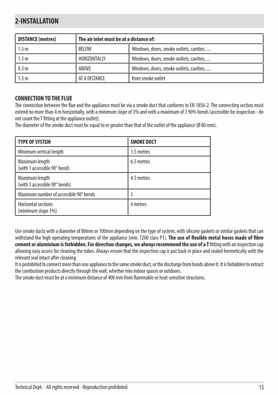
DISTANCE (metres) The air inlet must be at a distance of:
1.5 m BELOW Windows, doors, smoke outlets, cavities, ....
1.5 m HORIZONTALLY Windows, doors, smoke outlets, cavities, ....
0.3 m ABOVE Windows, doors, smoke outlets, cavities, ....
1.5 m AT A DISTANCE from smoke outlet
CONNECTION TO THE FLUEThe connection between the flue and the appliance must be via a smoke duct that conforms to EN 1856-2. The connecting section must extend no more than 4 m horizontally, with a minimum slope of 3% and with a maximum of 3 90% bends (accessible for inspection - do not count the T fitting at the appliance outlet).The diameter of the smoke duct must be equal to or greater than that of the outlet of the appliance (Ø 80 mm).
TYPE OF SYSTEM SMOKE DUCT
Minimum vertical length 1.5 metres
Maximum length (with 1 accessible 90° bend)
6.5 metres
Maximum length (with 3 accessible 90° bends)
4.5 metres
Maximum number of accessible 90° bends 3
Horizontal sections(minimum slope 3%)
4 metres
Use smoke ducts with a diameter of 80mm or 100mm depending on the type of system, with silicone gaskets or similar gaskets that can withstand the high operating temperatures of the appliance (min. T200 class P1). The use of flexible metal hoses made of fibre cement or aluminium is forbidden. For direction changes, we always recommend the use of a T fitting with an inspection cap allowing easy access for cleaning the tubes. Always ensure that the inspection cap is put back in place and sealed hermetically with the relevant seal intact after cleaning.It is prohibited to connect more than one appliance to the same smoke duct, or the discharge from hoods above it. It is forbidden to extract the combustion products directly through the wall, whether into indoor spaces or outdoors. The smoke duct must be at a minimum distance of 400 mm from flammable or heat-sensitive structures.
T
I
S
I
U
B
A
P
UI
IC
4
3D
2
I
E
V
U1
F
16
2-INSTALLATION
EXAMPLES OF CORRECT INSTALLATION
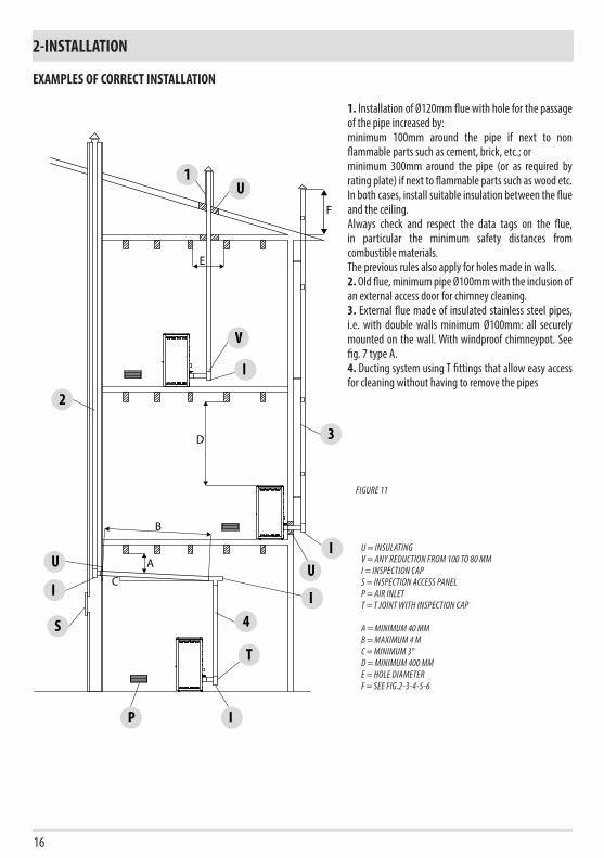
1. Installation of Ø120mm flue with hole for the passage of the pipe increased by:minimum 100mm around the pipe if next to non flammable parts such as cement, brick, etc.; orminimum 300mm around the pipe (or as required by rating plate) if next to flammable parts such as wood etc.In both cases, install suitable insulation between the flue and the ceiling.Always check and respect the data tags on the flue, in particular the minimum safety distances from combustible materials.The previous rules also apply for holes made in walls.2. Old flue, minimum pipe Ø100mm with the inclusion of an external access door for chimney cleaning.3. External flue made of insulated stainless steel pipes, i.e. with double walls minimum Ø100mm: all securely mounted on the wall. With windproof chimneypot. See fig. 7 type A.4. Ducting system using T fittings that allow easy access for cleaning without having to remove the pipes
FIGURE 11
U = INSULATINGV = ANY REDUCTION FROM 100 TO 80 MMI = INSPECTION CAPS = INSPECTION ACCESS PANELP = AIR INLETT = T JOINT WITH INSPECTION CAP
A = MINIMUM 40 MMB = MAXIMUM 4 MC = MINIMUM 3°D = MINIMUM 400 MME = HOLE DIAMETER F = SEE FIG.2-3-4-5-6
500
551
Ø80 Ø50Ø60
1105
311
170
Ø50 Ø80Ø60
256
5001668415892
17
3-DRAWINGS AND TECHNICAL FEATURES
Technical Dept. - All rights reserved - Reproduction prohibited
DRAWINGS AND CHARACTERISTICS
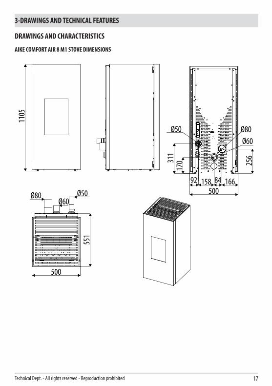
AIKE COMFORT AIR 8 M1 STOVE DIMENSIONS

18
3-DRAWINGS AND TECHNICAL FEATURES
TECHNICAL CHARACTERISTICS AIKE COMFORT AIR 8 M1Energy Efficiency Class A+Nominal output power 8,1 kW (6966 kcal/h) Minimum power output 2,3 kW (1978 kcal/h)Efficiency at Max 90,9%Efficiency at Min 92,6%Temperature of exhaust smoke at Max 188 °CTemperature of exhaust smoke at Min 89 °CParticulate /OGC / Nox (13%O2) 17 mg/Nm3 - 1 mg/Nm3 - 142 mg/Nm3CO at 13% O2 at Min and at Max 0,043 – 0,002%CO2 at Min and at Max 6,4% - 14,0%Recommended draught at Max*** power 0.10 mbar - 10 Pa***Minimum draft allowed at minimum power 0.05 mbar - 5 PaSmoke mass 4,3 g/secHopper capacity 39 litresType of pellet fuel Pellet diameter 6 mm and size 3÷40 mmPellet hourly consumption Min ~ 0,5 kg/h* - Max ~ 1,8 kg/h*Autonomy At min ~ 50 h* - At max ~ 14 h*Heatable volume m3 174/40 – 199/35 – 232/30 **Combustion air inlet Ø 50 mmSmoke outlet Ø 80 mmAir intlet 80 cm2
Rated electrical power (EN 60335-1) 81 W (Max 380 W)Supply voltage and frequency 230 Volt / 50 HzNet weight 190 kgWeight with packaging 205 kgDistance from combustible material (back/side/under) 120/200/0 mmDistance from combustible material (ceiling/front) 800/1000 mm
* Data that may vary depending on the type of pellets used ** Volume that can be heated, according to the power requirement per m3 (respectively 40-35-30 Kcal/h per m3) ***Value recommended by the manufacturer (non-binding) for optimal product operation
Tested according to EN 14785 in accordance with European regulation for Construction Products (EU 305/2011).

19
4-UNPACKING
Technical Dept. - All rights reserved - Reproduction prohibited
PREPARATION AND UNPACKINGThe packaging consists of a recyclable cardboard box in line with RESY standards and a wooden pallet. All packaging materials can be reused for similar use or eventually disposed of as urban solid waste, in compliance with the regulations in force.After having removed the packaging make sure the product is intact.
Handle the product with suitable means paying attention to the applicable safety regulations in force. Do not turn the packaging over and handle the majolica parts with care.
The stove is delivered in a single package with sides already assembled to the structure.Open the package, remove the cardboard, polystyrene and any straps and position the stove in the selected place making sure that it complies with the requirements.The stove body or unit must always be kept in a vertical position when handled, and handled using carts only. Pay particular attention to the door and its glass, protecting them from mechanical knocks that would compromise their integrity.If possible, unwrap the stove near the chosen area of installation.The packaging materials are neither toxic nor harmful.
•
AIKE STOVE PACKAGING

u
s
20
4-UNPACKING
Remove the stoves from the pallet by removing the two screws “u” and the plate “s” from the stove foot. There are four brackets “s”.
REMOVING THE FASTENING BRACKETS

J
J
21
4-UNPACKING
Technical Dept. - All rights reserved - Reproduction prohibited
Position the stove and connect it to the flue pipe. Use the four adjustable feet (J)to get the stove correctly levelled so that the smoke outlet is lined up with the connecting pipe. If the stove needs to be connected to an outlet pipe which goes through the rear wall (to connect to the flue), take utmost care to make sure that the joint is not forced.
If the stove smoke outlet is forced or used improperly to lift it or position it, the operation of the stove can be damaged irreparably. •
1. TURN THE FEET CLOCKWISE TO LOWER THE STOVE2. TURN THE FEET COUNTERCLOCKWISE TO LIFT THE STOVE

k
k
A
CB
22
5-CLADDING REMOVAL
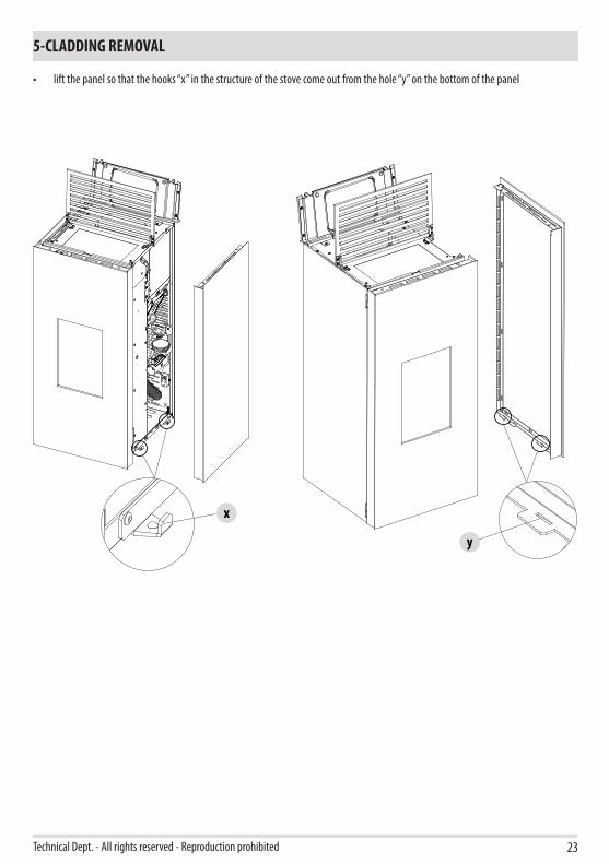
The Aike stove is delivered completed finished in a single package. Should it be necessary to remove the sides to perform an intervention in the stove, proceed as follows:• lift the front grid and the cover grid of the tank• loosen the two screws “k” to pull the panel off at the top• tilt the panel towards you
x
y
23
5-CLADDING REMOVAL
Technical Dept. - All rights reserved - Reproduction prohibited
• lift the panel so that the hooks “x” in the structure of the stove come out from the hole “y” on the bottom of the panel
24
5-CLADDING REMOVAL
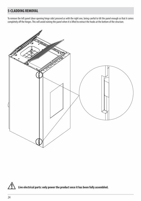
To remove the left panel (door opening hinge side) proceed as with the right one, being careful to tilt the panel enough so that it comes completely off the hinges. This will avoid ruining the panel when it is lifted to extract the hooks at the bottom of the structure.
Live electrical parts: only power the product once it has been fully assembled.

FZ
E
25
6-DOOR OPENING
Technical Dept. - All rights reserved - Reproduction prohibited
The stove is equipped with two doors:• to open the first aesthetic door “E”, just pull the top part with your hand (it is kept shut by a magnet)• to open the door of the firebox “F”, take the supplied tool “Z” and lift the hook
Attention!The firebox door must be closed properly for the stove to work correctly.
26
7-CONNECTIONS TO ADDITIONAL DEVICES
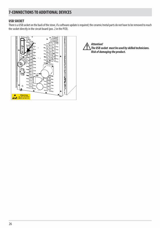
USB SOCKET There is a USB socket on the back of the stove, if a software update is required; the ceramic/metal parts do not have to be removed to reach the socket directly in the circuit board (pos. 2 in the PCB).
Attention!The USB socket must be used by skilled technicians.Risk of damaging the product.
VUSV
4
3
2
1
65
27
7-CONNECTIONS TO ADDITIONAL DEVICES
Technical Dept. - All rights reserved - Reproduction prohibited
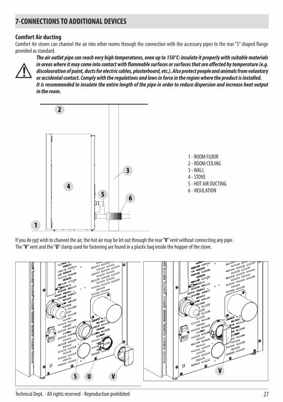
Comfort Air ductingComfort Air stoves can channel the air into other rooms through the connection with the accessory pipes to the rear “S” shaped flange provided as standard.
The air outlet pipe can reach very high temperatures, even up to 150°C: insulate it properly with suitable materials in areas where it may come into contact with flammable surfaces or surfaces that are affected by temperature (e.g. discolouration of paint, ducts for electric cables, plasterboard, etc.). Also protect people and animals from voluntary or accidental contact. Comply with the regulations and laws in force in the region where the product is installed.It is recommended to insulate the entire length of the pipe in order to reduce dispersion and increase heat output in the room.
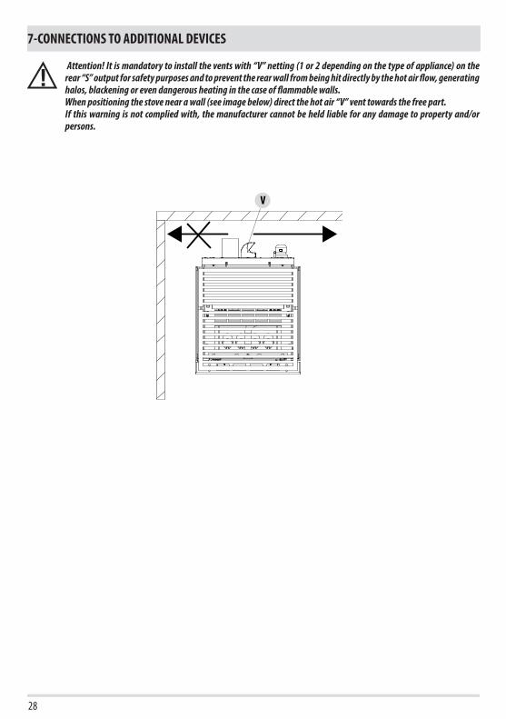
If you do not wish to channel the air, the hot air may be let out through the rear “V” vent without connecting any pipe.The “V” vent and the “U” clamp used for fastening are found in a plastic bag inside the hopper of the stove.
1 - ROOM FLOOR2 - ROOM CEILING3 - WALL4 - STOVE5 - HOT AIR DUCTING6 - INSULATION
V
28
7-CONNECTIONS TO ADDITIONAL DEVICES
Attention! It is mandatory to install the vents with “V” netting (1 or 2 depending on the type of appliance) on the rear “S” output for safety purposes and to prevent the rear wall from being hit directly by the hot air flow, generating halos, blackening or even dangerous heating in the case of flammable walls.When positioning the stove near a wall (see image below) direct the hot air “V” vent towards the free part.If this warning is not complied with, the manufacturer cannot be held liable for any damage to property and/or persons.
I/ON
29
7-CONNECTIONS TO ADDITIONAL DEVICES
Technical Dept. - All rights reserved - Reproduction prohibited
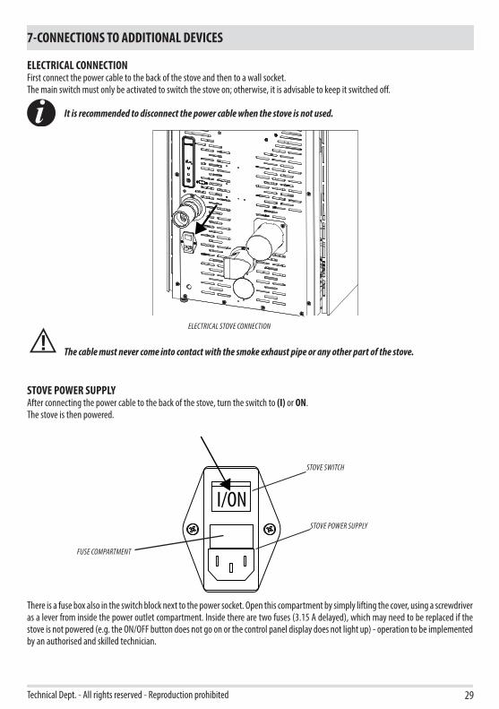
ELECTRICAL CONNECTIONFirst connect the power cable to the back of the stove and then to a wall socket.The main switch must only be activated to switch the stove on; otherwise, it is advisable to keep it switched off.
It is recommended to disconnect the power cable when the stove is not used.
The cable must never come into contact with the smoke exhaust pipe or any other part of the stove.
STOVE POWER SUPPLYAfter connecting the power cable to the back of the stove, turn the switch to (I) or ON.The stove is then powered.
There is a fuse box also in the switch block next to the power socket. Open this compartment by simply lifting the cover, using a screwdriver as a lever from inside the power outlet compartment. Inside there are two fuses (3.15 A delayed), which may need to be replaced if the stove is not powered (e.g. the ON/OFF button does not go on or the control panel display does not light up) - operation to be implemented by an authorised and skilled technician.
ELECTRICAL STOVE CONNECTION
STOVE POWER SUPPLY
STOVE SWITCH
FUSE COMPARTMENT

30
8-LOADING THE PELLETS
LOADING THE PELLETSFuel is loaded from the upper part of the stove by lifting door .Pour the pellets in slowly so that they are deposited at the bottom of the hopper.
If loading pellets when the stove is running, open the door of the tank using the stove mitten that comes with the stove itself. When loading, do not let the pellet bag come into contact with hot surfaces. Never remove the protection grid inside the hopper. No other type of fuel other than pellets is to be inserted into the hopper, in compliance with above-mentioned specifications. Store the spare fuel at an adequate safe distance.Do not pour pellets directly onto the brazier but only into the hopper.When the appliance is running and when it is turned off, most of the stove surfaces are very hot (door, handle, glass, smoke outlet pipes, etc.). Therefore it is recommended to avoid coming into contact with these parts.


05/06/2019REV.18901865000
MCZ GROUP S.p.A.Via La Croce n°8
33074 Vigonovo di Fontanafredda (PN) – ITALYTelephone: +39 0434/599599 r.a.
Fax: +39 0434/599598Internet: www.mcz.it
e-mail: [email protected]


