Polytetrafluoroethylene (PTFE) has been used for gasketand other sealing purposes for several decades, not long af-ter its invention in 1938 by Plunkett [1], a DuPont scientist.The excellent chemical resistance combined with its rela-tively high melting temperature has made the material suit-able for many chemical processing applications. Only a fewchemicals, such as elemental fluorine, molten alkali metals,and some inter-halogen compounds, can react with PTFE.
Unfortunately, a critical drawback of virgin PTFE mate-rial (i.e. original form without additives or additional pro-cessing to alter the properties) is its lack of strength undertension, or its low cold-flow resistance. This property hasgreatly limited the use of the material, because it tends tolose bolt loads due to continuous loss of thickness under
constant compression which, in turn, leads to deteriorationof sealability. Much effort has been devoted to solving theproblem, such as adding filler materials to improve its creepresistance, but these attempts produced only limited success.
The low-strength problem of PTFF was finally overcomewith the invention of expanded PTFE material by Gore [2].The newly developed material is soft but strong, easily com-pressible and able to seal irregular surfaces, while maintain-ing its excellent chemical compatibility to most substances.It has gradually earned acceptance by the chemical process-ing and other related industries as one of the most versatilegasket materials available in the market. The earlier prod-uct of expanded PTFE gasket material was joint sealant,a rope-form material which can be laid on flange surfacesas replacement of traditional sheet gaskets. This materialis made by a uni-axial expansion process, with very strongstrength parallel to the stretching direction, but relativelyweak in other directions. The sheet form of expanded PTFEwith more even multidirectional tensile strength was intro-
J. Huang, W. Lee / Materials Chemistry and Physics 68 (2001) 180–196 181
duced to the market much later. Because of the difficultmanufacturing process, currently there are only a handful ofcompanies in the world capable of producing such a sheetmaterial.
Here, we will present sealing and mechanical propertiesof expanded PTFE gasket sheets, characterized by the roomtemperature tightness test (ROTT) developed by the Pres-sure Vessel Research Council (PVRC). The tested, expandedPTFE sheet samples were manufactured by Yeu Ming TaiChemical Industrial Company, and were isotropic in termsof tensile strength and deformation characteristics (i.e. uni-form tensile strength along all horizontal directions), prop-erties not seen in any other expanded PTFE sheets availableon the market. The ROTT test results of the expanded PTFEwill be explored for the effect of thickness and sheet density,and further compared with a skived, virgin PTFE sheet anda filled PTFE gasket. An overview of these various types ofPTFE-based materials was provided by Latte and Coomber[3]. But before we present the detailed ROTT experimentalresults, it is essential to review the current gasket charac-terization techniques, and the reasons as to why the ROTTmethod is selected as a tool for evaluation of a gasket’s seal-ing performance.
As people grow more concerned about environmental pro-tection issues (Clean Air Act of 1990), sealing performanceof a gasket becomes the central criterion among all gasketselection considerations. There are two major forces actingupon a gasket which affect the gasket sealability, namely thegasket compressive stress created by tightening of bolts, andthe internal pressure caused by process fluids. Generally, ahigher stress results in a less leakage, while higher internalpressures correspond to higher leak rates. The actual jointleakage is thus the net effect of these two competing factors,and the ability of a gasket to maintain the applied compres-sive stress is essential to the control of joint leakage.
Traditionally, the physical properties related to sealingperformance of a gasket have long been characterized bythe ASTM series of testing, such as F36 for compressibilityand recovery, F37 for sealabilty, and F38 for creep relax-ation. More specifically, F37 measures gasket leakage at aconstant gasket stress and internal fluid pressure. It is worthnoting that test conditions for F37 may vary based upona manufacturer’s preference, or agreements between man-ufacturers and gasket users. F36 characterizes short-termgasket thickness change under compression and decompres-sion. A highly compressible gasket is expected to conformto surface irregularity of a flange, and hence take away theleakage paths at the interface between a gasket and flange(i.e. tangential leakage). A gasket with higher recovery isnormally considered to respond better with bolt-load reduc-tions in maintaining good surface contact, thus preventingsignificant increase of tangential leakage. This is particu-larly true for many rubber-based materials. However, inter-nal fluid may also permeate through a gasket, another ma-jor leakage mechanism, and decompression of a gasket withhigh recovery may actually open up the permeation leakage
paths of the gasket, and cause higher leak rates. Creep relax-ation, as measured by the F38 method, indicates a transientstress–strain condition in which the strain increases concur-rently with decay of stress, i.e. a measurement of bolt-loadreduction associated with the loss of thickness after an ex-tended period of time under compression. As load is de-creased, leakage increases.
These ASTM tests are simple to carry out and understand,and do provide some insight into the sealing performance ofa gasket. However, the test results cannot be used for a moredetailed, quantitative evaluation of gasket performance. Forexample, the actual plant processes are performed at count-less compression and pressurization conditions, while F37only gives a leakage value for a specified stress and fluidpressure condition. When regulations for an industry re-quire a specific maximum leakage level, the information onproper compressive loads cannot be obtained by the F37standard. The compressibility, recovery and creep relaxationtests (F36 and F38) characterize gasket behavior in responseto stress increase and decrease, but tell little about how thesewould correlate with the actual leakage changes. In short,these methods do not reveal much information on how seal-ing functions of a gasket change with different loading andpressurization conditions, so have a very limited ability topredict what would be required to achieve a satisfactory sealfor a process application. Also, because manufacturers maychoose to present data at their preferred conditions (such asgasket stress, thickness, and internal pressure), this some-times makes comparison of results among different materi-als more difficult and confusing.
Furthermore, these test results are not incorporated in theconventional American Society of Mechanical Engineers(ASME) bolted-joint design rules (ASME Boiler and Pres-sure Vessel Code, Section VIII, Division 1). Instead, theASME code is based on a set of rules using empirical gas-ket factor ‘y’ for gasket seating yield and a factor ‘m’ foroperating load maintenance in pressurized service. Unfortu-nately, as pointed out by Derenne et al. [4], the ‘m’ and ‘y’factors cannot be “verified by test, nor can they be rationallyextended to new products and materials because there is noworkable standard test procedure.” In addition, “it is implicitin the concept represented by ‘m’ and ‘y’ that the code rulesonly consider whether or not a gasketed joint is structurallysafe and is mute on the question of tightness performance.”That is, no leakage information can be derived from the twofactors.
The Tightness Testing and Research Laboratory (TTRL)of Ecole Polytechnique, has developed a series of new‘leakage-based’ testing methods for characterizing physicaland functional properties of a gasket. The ROTT test is oneof the newly developed testing methods, and has becomewidely adopted by the fluid sealing industry as a useful toolfor evaluating sealing performance of a gasket. The methodnot only measures gas leak rates and gasket deflection(loss of thickness) during the gasket assembly stage (i.e.initial loading or tightening), but also those during gasket
182 J. Huang, W. Lee / Materials Chemistry and Physics 68 (2001) 180–196
decompression (unloading) to simulate operating condi-tions. Leakage measurements at various gasket stresses andhelium pressures are to be performed, and the results willmore realistically reflect the leakage behavior of a gasketunder actual plant conditions. Because all gaskets will betested by the same set of test conditions, direct comparisonof the leakage data between two different gaskets becomespossible, and will readily reveal the sealing performancedifferential of the two. New gasket constants which replacethe functions of ‘m’ and ‘y’ can be further determined fromthese leakage results for interpolation and extrapolation ofgasket behavior to other compression and pressurizationstates, and for bolted joint design purposes [4,5].
2. Experimental methods
2.1. ROTT test procedure and conditions
The test equipment, a room-temperature hydraulic test rig,was designed by TTRL to achieve a uniform gasket-loaddistribution in order to eliminate uneven bolt tightening andflange rotation effect [6]. The tested ring gasket is normallycut to an OD of 5.875 in. and ID of 4.875 in., with a gasketcontact area of 8.44 in2. Gasket stress values in the tests arecomputed based on this initial contact area without consid-ering any increase in gasket area upon loading. The rig isconnected to a variety of leak measurement systems, capableof detecting leakage of the standard fluid, helium, and someother fluid types. For the PTFE-based materials with tightseals, the majority of measurements were done by a massspectrometer (good for leaks down to 10−8 mg s−1). Pres-sure decay and pressure rise methods (acceptable to 5×10⁻⁴
and 5×10⁻⁶ mg s−1, respectively) were also used for higherleakage measurements at lower gasket stresses. For theseminute leak rates, measurement uncertainties of up to±20%may be expected.
The test includes two parts: the Part A sequence repre-sents the sealing performance of a gasket during initial jointtightening and gasket seating, and Part B simulates the oper-ating conditions by performing unload–reload cycles at threegasket seating stresses. For verification of test consistency,normally two tests for each gasket material are conducted.Part A test data is used to determine the required seatingload which is similar to the ‘y’ factor in the current ASMEcode. Part B data is for the determination of the requiredoperating gasket load, and is similar to the function of fac-tor ‘m’ in the code. There are five main gasket stress levels,S1–S5, and three intermediate levels, S2.5, S3.5, and S4.5,in each test. For PTFE-based materials, the main stresses are1025, 3040, 5390, 7750, and 10 110 psi, and the additionalones are 4215, 6570, and 8930 psi.
The general sequence of an ROTT test is illustrated inFig. 1, using gasket deflection measurements as an exam-ple, with the load sequence shown by arrows. In Part A,
Fig. 1. ROTT test procedure (see arrow directions) expressed in terms ofgasket stress vs. deflection.
deflection of a gasket is measured at each new level of com-pression stress which is higher than any previously appliedstress. Leakage of a gasket is also measured with heliumpressure of 400 psig at S1, and with pressures alternatingbetween 400 and 800 psig (filled and open squares) at S2,S3, S4 and S5. The Part A test is interrupted with unload-ing sequences (open triangles) at S3 (to S2 and S1; PartB1), S4(−S3−S1; B2) and S5(−S4−S1; B3). At the end ofthe B1 and B2 sequences, the gasket is reloaded to S3 andS4, respectively, to complete the unload–reload cycles, andthen the test is continued to the next testing stress level forPart A. During these cycles, helium pressure is maintainedat 800 psig. The test is completed when the B3 sequence isunloaded to S1. An option at the end of a RQTT test is acrush test in which the gasket is performed with a series ofunload–reload cycles until a massive leak occurs, or until40 000 psi gasket stress is reached, whichever comes first.
As ROTT test results must reflect the true tightness behav-ior of a gasket in long term, stable conditions, not the transi-tory leakage behavior which occurs after a change in stressor pressure, TTRL [7] has investigated the effect of dwelltime on leakage stabilization. The current procedure adoptsa dwell time of 1.5–5 h during which leakage is measuredevery 15 min after 1.5 h of waiting period, until it reachesthe stabilization value or the 5 h maximum. Internal pressure(P) and gasket stress (Sg) remain constant during each setof 15 min incremental measurements on leakage and deflec-tion, until the leak rate approaches stabilization, then eitherP or Sg, or both, are changed for the next series of measure-ments for a different set of conditions.
2.2. Materials
ROTT test will be shown for three expanded PTFE gas-ket samples: regular type of 1/16 and 1/8-in. thick sheetswith density of 0.85 g cm−3, and rigid type of 1/8-in. thicksheet with density of 1.2 g cm−3. The tolerances for thick-
J. Huang, W. Lee / Materials Chemistry and Physics 68 (2001) 180–196 183
Fig. 2. Tightness parameter vs. gasket stress for the regular 1/8-in. expanded PTFE sheets, converted from leakage data of Fig. 3 using Eq. (1). Line(1) is the PVRC idealized gasket assembly line (defined by Gb and ‘a’), and the set of lines (2) indicates the current PVRC simplified unload–reloadcycles, converging to a single point of Gs.
ness and density of the sheets are generally of the order of±10–15%, typical of expanded PTFE materials. The twothicknesses are the most common sheet sizes used in pro-cess applications: The regular 1/8-in. sheet was tested inthe PTFE Gasket Qualification Project during 1992–1994,and reported in Ref. [7]. The regular 1/16 in. results wereobtained recently (June 1999), showing a slight sealabilityimprovement over an earlier version of the 1/16 -in. sheetalso tested in the PTFE Gasket Qualification Project [7]. Therigid 1/8-in. sheet was developed in 1998 for better handlingcapability in difficult installation conditions where regularsheets may be less favorable due to their softness. The sheetwas tested in June 1998.
2.3. Presentation and interpretation of leakage data fromROTT tests — tightness concept and new gasket constants
A major purpose of ROTT tests is to provide aleakage-based guideline for better bolted joint design rules.This is achieved by the introduction of the ‘tightnessconcept’, and the associated PVRC gasket constants Gb,‘a’ and Gs. Gasket tightness is a measure of its ability tocontrol the leak rate of the joint for a given load [6]. Thetightness parameterTp, which combines the internal fluidpressure and the mass leak rate (Lrm), is defined as follows:
Tp = P
P ∗
(Lrm∗
Lrm
)0.5
(1)
whereP∗ is the reference pressure of I atm (14.7 psig), andLrm∗ the unit mass leak rate of 1 mg s−1.
Fig. 2 shows the tightness values of the 1/8-in. expandedPTFE sheet, converted from the leakage data presented inFig. 3, with both tightness and gasket stress expressed aslogarithmic values. It shows that, for the Part A data, gas-ket tightness increases with increasing gasket stress The ini-tial seating (or assembly) curve defined by the data forms aconvex ‘knee’, i.e. the slope of the curve decreases with in-creasing gasket stress — this is called ‘tightness softening’.Some gaskets have a well-defined knee, while others have aknee that is fuzzy and less well defined. In contrast, ‘tight-ness hardening’ defines a condition where a reverse kneeoccurs and the slope of the initial-seating curve increaseswith increasing gasket stress. Fig. 2 shows that the effect forthe expanded PTFE sheet is insignificant.
In general, a line can be defined by those higher-stressdata above the knee, and this is considered to represent‘seated’ tightness data. The slope and the intercept of theline atTp=1 are defined as gasket constants ‘a’ and Gb, re-spectively. These new gasket constants can be derived by alinear regression procedure with selected data, as detailed byDerenne and Payne [8]. The corresponding values and theassembly line (1) for the 1/8-in. expanded PTFE sheet areshown in Fig. 2. The relationships between assembly gas-ket stress (Sga) assembly tightness (Tpa) and the two gasketconstants can be expressed by Eq. (2):
Sga = Gb× Tpaa (2)
The required seating stress can thus be estimated from theequation provided that a tightness requirement for the appli-cation is defined.
184 J. Huang, W. Lee / Materials Chemistry and Physics 68 (2001) 180–196
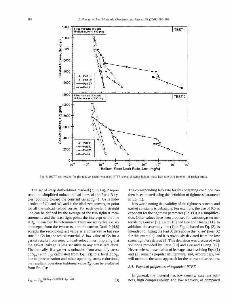
Fig. 3. ROTT test results for the regular 1/8 in. expanded PTFE sheet, showing helium mass leak rate as a function of gasket stress.
The set of steep dashed-lines marked (2) in Fig. 2 repre-sents the simplified unload–reload lines of the Parts B cy-cles, pointing toward the constant Gs atTp=1. Gs is inde-pendent of Gb and ‘a’, and is the idealized convergent pointfor all the unload–reload curves. For each cycle, a straightline can be defined by the average of the two tightest mea-surements and the least tight point; the intercept of the lineatTp=1 can then be determined. There are six cycles, i.e. sixintercepts, from the two tests, and the current Draft 9 [4,8]accepts the second-highest value as a conservative but rea-sonable Gs for the tested material. A low value of Gs for agasket results from steep unload–reload lines, implying thatthe gasket leakage is less sensitive to any stress reduction.Theoretically, if a gasket is unloaded from assembly stressof Sga (with Tpa calculated from Eq. (2)) to a level ofSgodue to pressurization and other operating stress reductions,the resultant operation tightness valueTpo can be evaluatedfrom Eq. (3):
Tpo = Tpalog(Sgo/Gs)/log(Sga/Gs) (3)
The corresponding leak rate for this operating condition canthen be estimated using the definition of tightness parameterin Eq. (1).
It is worth noting that validity of the tightness concept andgasket constants is debatable. For example, the use of 0.5 asexponent for the tightness parameter (Eq. (1)) is a simplifica-tion. Other values have been proposed for various gasket ma-terials by Guizzo [9], Latte [10] and Lee and Huang [11]. Inaddition, the assembly line (1) in Fig. 4, based on Eq. (2), isintended for fitting the Part A data above the ‘knee’ (near S2for this example), and it is obviously deviated from the lowstress tightness data at S1. This deviation was discussed withsolutions provided by Latte [10] and Lee and Huang [12].Nevertheless, presentation of leakage data involving Eqs. (1)and (2) remains popular in literature, and, accordingly, wewill maintain the same approach for the relevant discussions.
2.4. Physical properties of expanded PTFE
In general, the material has low density, excellent soft-ness, high compressibility, and low recovery, as compared
J. Huang, W. Lee / Materials Chemistry and Physics 68 (2001) 180–196 185
Fig. 4. Gasket deflection as a function of gasket stress for the regular 1/8 in. expanded PTFE sheet.
to other types of PTFE-based products, such as filledPTFE. The relevant values can be seen in Table 1. No-tice that the ASTM test results of the filled PTFE inTable 1 provided by the manufacturer were done withthe 1/32-in. thickness, a size seldom used in practice. Notest result for the skived, virgin PTFE is available to us,except that the density of virgin PTFE is known to be2.1 g cm−3. Nevertheless, skived, virgin PTFE is expectedto be slightly more compressible upon loading, but re-cover less during unloading compared to the filled PTFEmaterial, due to the lack of hard fillers for the former.Sealability and creep relaxation test results are also pro-vided in Table 1 for reference purposes only. No furtherdiscussion will be carried out regarding these ASTM testresults, because of their very limited values in assessingthe sealing performance of a gasket, for reasons indicatedpreviously.
Table 1Typical physical properties of expanded PTFE and filled PTFE sheetsa
aNo test result for the skived, virgin PTFE (density 2.1 g cm−3) is available.bNot available.
3. Results and discussions
Typical ROTT test results are presented with the formatsshown in Figs. 3 and 4, using test data for one of the tested,expanded PTFE sheets (1/8 in. thick, density 0.85 g cm−3)as an example. Fig. 3 presents all the incremental deflectionmeasurements. This type of graph can be used to assess thecold-flow resistance of a gasket. Fig. 2 shows the heliummass leak rates, recorded at the end of each dwell time. Theseresults confirm that with increasing stress, the gasket deflec-tion increases, while leakage is reduced. In this paper, wewill primarily focus on the presentation of test data in thesetypes of graphs. However, for further interpretation of leak-age behavior, extension of leak rates to untested stress lev-els, and for formulation of bolted-joint design rules, PVRChas introduced a new parameter to represent tightness of agasket, as summarized in Section 3.1.
186 J. Huang, W. Lee / Materials Chemistry and Physics 68 (2001) 180–196
Fig. 5. (a) Gasket deflection of the regular 1/16 and 1/8 in., and rigid 1/8 in. expanded PTF sheets. (b) Gasket deflection normalized against initialthickness of a gasket for the three expanded PTFE samples; two tests each.
3.1. 1/8 in. thick expanded PTFE sheet
Figs. 3 and 4 illustrate the ROTT test data for the regu-lar 1/8-in. thick expanded PTFE sheet, expressed in termsof gasket deflection and leakage versus gasket stress. Fig. 4,showing the deflection results, is a collection of the l5-minincremental measurements during the tests. The dwell timesfor leakage stabilization of expanded PTFE gaskets are nor-mally of the order of 3-4 h or longer, except at S1 whenleakage is high, and long waiting periods are unnecessary. Itcan be seen in the figure that tests 1 and 2 of the sheet typeproduced nearly identical results. Upon compression (PartA), the gasket thickness decreased significantly at the S1level, but it became much more difficult to compress the gas-ket at higher stresses, with only a small thickness change inresponse to stress increase. The continued thickness lossesdue to the dwell times were small after the initial stress in-
creases, forming narrow ‘plateaus’ at the stress levels of S3,S4 and S5. The width of such a plateau gives an indicationof a gasket’s ability to resist creeping or cold flow undercompression; normally the narrower a plateau, the better thecold-flow resistance. The Part B unloading deflection re-sults form steep curves with only small thickness increasescorresponding to the stress reductions. This is indicative oflimited thickness recovery. This overall deflection pattern istypical of all expanded PTFE gasket products (i.e. Fig. 5),confirming high compressibility, high cold-flow resistance,and low recovery of the material.
Fig. 3 shows results of helium mass leak rate as a functionof gasket stress. The solid and dotted lines represent PartA and Parts B data, respectively. In these graphs, each datapoint represents the final measurement of a dwell time. Dueto the softness and high surface conformability of the sheet,it is believed that with a moderate compressive load, the
J. Huang, W. Lee / Materials Chemistry and Physics 68 (2001) 180–196 187
internal fluid leaks mostly by permeating through the gasket,not by tangential leakage through the interface of gasket andflange. The high leak rates at low stress levels, such as S1 andS2, are therefore interpreted as a result of high porosity, andhence high permeability, of the material at these stresses. Thesealing performance is quickly improved over the intervalof S1 to S3 levels (by over 105 times), although the rate ofleakage reduction becomes smaller above S3. For Parts B,the leak rate at S1 is increased by about 5–15 times from theinitial unloading points (i.e. S3, S4 and S5 levels). Again,this type of leakage behavior in Fig. 3 is very common forexpanded PTFE material.
The tightness values corresponding to the leak rates ofFig. 3 are illustrated in Fig. 2, with the derived gasket con-stants also shown. As discussed previously, the assemblyline (1) is deviated from the actual data at S1, but it fitsvery well with the data above S2 with tightness value of∼100. This defines the lower limit of the applicable rangefor the assembly line. The validity of an assembly line athigh stresses is greatly influenced by the extent of tightnesshardening effect. For the expanded PTFE sheet shown withnot much of this effect, line (1) is suitable up to the S5 levelof the tests. The dashed lines defined by the constant Gs inFig. 2 are intended for describing the unloading data of thesheet, but they match only some of the Parts B cycles. Thisis due to the fact that these unloading curves actually do notconverge to a single Gs value. However, for the simplicityof using Gs for bolted-joint design, this discrepancy is notavoidable.
3.2. Effect of thickness and sheet density
Test results of the various expanded PTFE types are com-pared in Figs. 5–7. Fig. 6a presents the typical ‘continuous’(15-min incremental) gasket deflection results for the regu-lar 1/16 and 1/8 in., and rigid 1/8 in. sheets. All three gasketsshow a similar gasket deflection pattern, i.e. a large increase
Fig. 6. Comparison of Part A data between the regular 1/16 and 1/8 in. expanded PTFE sheet at (a) 400 and (b) 800 psig, and between the regular 1/8and rigid 1/8 in. sheets at (c) 400 and (d) 800 psig.
near S1, but much smaller changes above S3 under loadingand unloading conditions. The separations of the deflectiongraphs among these gaskets are largely affected by the initialthickness differences, although to a lesser extent also influ-enced by property changes associated with density variation(such as compressibility and cold-flow resistance).
In order to take into account the effect of thickness, thedeflection values can be normalized against the initial thick-ness of a gasket. The sheets were measured at 0.067 in.for the regular 1/16 in., 0.112 in. for the regular 1/8 in., and0.125 in. for the rigid 1/8 in.. The results are presented inFig. 5b, the deflection values recorded at the end of eachstabilization period normalized to the actual initial thick-nesses of the sheets. Only Part A data is shown in the figurefor better visualization. The measurements reflect the com-bined effect of compressibility and creeping. It is worth not-ing that the extent of thickness change at each stress levelis not only a result of stress increase, but also affected bythe length of the corresponding dwell time; longer the time,larger the deflection. Although the required dwell times forexpanded PTFE are generally similar, they did not remainconstant for each stress level of a test, nor were they fixedfrom test to test in our study. Therefore, the interpretationof the deflection data should be very careful, and the anal-ysis may only be considered as semi-quantitative due to thelarge uncertainties associated with the varied dwell times.
Nonetheless, for each tested expanded PTFE type, thereis an excellent agreement between test 1 and test 2 data.All three sets of curves (i.e. two curves for each material)are also sub-parallel to each other, pointing to a similar me-chanical behavior among the three types of materials undercompression. There is a small (several percents) but notice-able difference between the regular l/l6 and 1/8-in. data.This might result from the normal compressibility and den-sity variations of expanded PTFE, the effect of thickness,different dwell times required for a different thicknesses, ora combination of these factors. However, the results appear
188 J. Huang, W. Lee / Materials Chemistry and Physics 68 (2001) 180–196
Fig. 7. Comparison of Parts B data for expanded PTFE in terms of initial leak rate reached before unloading vs. the final leak rate at the lowest testedstress level, all at 800 psig helium pressure: (a) regular 1/16 against 1/8 in., and (b) regular 1/8 against rigid 1/8 in.
to indicate a consistent mechanical behavior of the regularsheet regardless of thickness. The lower deflection values ofthe rigid 1/8 in., as compared to those of the regular, sheetscan be largely explained by the difference in density whichresults in lower compressibility of the rigid sheet.
Theoretically, the slopes of the curves in Fig. 5b may beused to quantify the cold-flow resistance of a material, pro-vided that deflection is measured with a constant dwell time.For example, a steep deflection curve normally implies alower tendency for a gasket to creep under constant com-pression, although the portion of the initial thickness loss,as a result of stress increase, needs to be subtracted. Forthe expanded PTFE, compressed to S3 and beyond, the de-gree of this initial thickness change is comparable amongthe three gaskets (see Fig. 5a). and, therefore, the slopesmay be directly compared to assess the creeping propertyof the various expanded PTFE sheets. For the regular 1/16and 1/8, and the rigid 1/8 in. sheets, the slopes between S3and S5 are estimated at 87–107, 87–96 and 58–63 ksi (i.e.1 Ksi= 1000 psi), respectively. Considering the uncertain-ties of the deflection results in Fig. 5b, as discussed above,it appears that the two regular sheets behave similarly, whilethe rigid sheet creeps slightly more than the regular sheets.
Fig. 6 compares helium mass leak rates of the regular1/16 versus 1/8 in. sheets (Fig. 6a and b)) and the regular1/8 versus rigid 1/8 in. sheets (Fig. 6c and d). These arePart A results for initial gasket seating and tightening. Toavoid complication of the comparison due to overlapping toomany data points, the results for the two helium pressures,400 and 800 psig, are illustrated separately. Fig. 5a and bshow that the regular 1/16 in. sheet leaks slightly less thanthe 1/8 in. sheet, by about 2–4 times at both 400 and 800 psiof pressures. Sonic data points for the two different sizeseven overlap with each other. The only exception occurs atS2.5 with 800 psig (Fig. 6b). where the arrow (1) points to200 times higher leakage for the 1/8 in. sheet. However, thisoccurs at the area where a slightly lower stress will signifi-cantly increase the leakage of a gasket (i.e. shallow Part A
curve). As shown in Fig. 6b, the actual stresses of the 1/8 in.tests at the S2.5 level are lower than those of the 1/16 in.tests (∼3800 psi vs.∼4200 psi). This small stress variationis likely to contribute to most of the leakage difference be-tween the two materials. Indeed. the stress required for the1/8 in. sheet to achieve the same leak rate as the 1/16 in.sheet at S2.5 (4200 psi), as estimated by triangle (2), is only20% over the S2.5 level of the 1/16 in. tests. The perfor-mance levels of the two sizes as suggested by the requiredstresses are thus not very different.
Fig. 6c and d illustrate the leakage variation with sheetdensity. One test of the rigid 1/8 in. sheet overlaps almostentirely one of the regular 1/8 in. test, while the second testleaks slightly more than the first, except at the S3 level wherean 8–15 times differences are observed. These graphs indi-cate a comparable leakage behavior between the materialsof two densities, although the regular sheet seals slightlytighter than the rigid one.
In summary, the test-to-test consistency for each type ofthe expanded PTFE in Fig. 6 is good. The results appearto indicate that (1) the thinner expanded PTFE sheet sealsslightly better than the thicker one; and (2) the regular sheetseals slightly better than the rigid sheet of higher density.But, in either case, the difference may be statistically in-significant.
It appears to be more difficult to quantify the behaviorof Parts B data for unload–reload cycles in a format suchas Fig. 3, due to the complexity of decompression behaviorof a gasket. The final leakage increase upon unloading isnot only influenced by the amount of stress reduction, butis also a function of compression and leakage state reachedbefore unloading. As a result, each seating stress level willdefine a unique unloading curve during decompression. Cur-rently PVRC recommends the use of Gs to characterize theParts B data of a material, as illustrated in Fig. 2. This isa tightness-based interpretation and formulation. It shouldbe noted that the invention of the constant is for mathe-matical convenience, aiming at simplifying the bolted-joint
J. Huang, W. Lee / Materials Chemistry and Physics 68 (2001) 180–196 189
design rules. It is not intended for a more in-depth anal-ysis of physical characteristics of this unload–reload pro-cess. Lee and Huang [12] presented an alternative approach,defining a recovery index to quantify degrees of tightnesschange during unloading. A similar concept to this recov-ery index, using leakage data directly, involves comparisonbetween the final and initial leak rates of an unload se-quence, and the results based on this concept are presented inFig. 7.
Fig. 7 illustrates the Parts B results of the three expandedPTFE types. The graphs plot initial leak rate of each unload-ing cycle (B1, B2, and B3 from the S3, S4 and S5 levels)versus the final leak rate of the cycle at the lowest stress levelS1. Data points of B1, B2 and B3 cycles from a same testare linked by straight lines, with sequence of the three cyclesindicated by the arrow direction shown. The effect of stresscannot be clearly expressed in the diagram, but for each setof B1–B3 data, lower initial leakage generally correspondsto higher compressive load reached before decompression.There are four 45◦ lines marked withR=1, 10, 100, and1000.R is the ratio of final-to-initial leak rates of a cycle,i.e. the degree of leakage increase after decompression, andthese lines are examples of contours of constantR. A PartB point located on the contour of 10 indicates 10 times ofleakage increase after unloading. If a B1–B3 curve falls ona constantR contour, this indicates a same magnitude ofleakage ‘recovery’ for each Part B cycle of a test. Becauseleakage always increases with decreasing gasket stress, allParts B data should fall on the upper left domain aboveR=1of the graphs.
Fig. 7a compares the unloading results of the regular 1/16and 1/8 in. sheets. As shown in Fig. 6a and b, the 1/16 in.sheet seals better than the 1/8 in. in Part A data (i.e. ini-tial leak rates), and this is reflected in Fig. 7a. Interestingly,these 1/16 and 1/8-in. values appear to form a trend some-what parallel to the contour ofR=10, limited to a relativelynarrow range ofRbetween 4 and 18. This indicates a similar‘recovering’ leakage behavior of the expanded PTFE sheets,regardless of thickness. In Fig. 7b, the results for the regularand rigid 1/8 in. sheets are compared (circles and squares,respectively), showing a similar trend as observed in Fig. 7a,although the rigid sheet data span a wider range ofR, from3 to 30.
Table 2PVRC gasket constants of the expanded PTFE, skived, virgin PTFE, and filled PTFE gasket sheets
Material Type Thickness (in.) Gb (psi) a Gs (psi) Tpmax Sgmax (psi)
aDetermined by the corresponding tightness hardening limit (the average of two tightest points).
3.3. Gasket constants of the expanded PTFE sheets
The gasket constants for the three expanded PTFE gas-kets are listed in Table 2, and the resultant assembly andunload–reload lines (i.e. design lines) are compared in Fig. 8.The corresponding data points are omitted from the figurefor clearer visualization. The upper limit for the applicablerange of an assembly line is constrained by the tightnessmaximum (Tpmax) and stress maximum (Sgmax) for a gasketshown in Table 2. There is no tightness hardening detectedfor the regular 1/8 in. sheet according to the current data re-duction procedure [8], and itsTpmax is simply the maximumtightness value obtained from the tests. The correspondingSgmax is then calculated using Eq. (2). For the other twogasket types, tightness limit due to the hardening effect isdefined based on the average of the two tightest points fromthe tests for each gasket, and this value is adopted forTpmaxin the table. The values ofSgmax for these two gaskets, alsocalculated with Eq. (2), are close to the actual maximumtesting stress S5, indicating that the effect of tightness hard-ening is not very significant.
All the expanded PTFE gaskets show similar behavior atlow stresses where the assembly lines and the actual testingdata do not agree. The corresponding ‘knees’ occur roughlyat S2 andTp of 100, which defines the lower tightness limitfor the applicable ranges of the assembly lines. Fig. 8 showsthat the general patterns for tightness changes during gasketcompression and decompression of the three gaskets are verysimilar. The three assembly lines for Part A data of thevarious gasket types are roughly parallel to each other, whilethe slopes of the nine calculated unload–reload lines (fromS3, S4 andSgmax) for Parts B are also comparable. However,within the applicable range of the design lines, the regular1/8 in. seals slightly tighter than the rigid 1/8 in. for a givenstress, while the regular 1/16 in. sheet is the tightest amongthe three gasket types. These observations are consistentwith the findings from Figs. 5–7, discussed above.
3.4. Comparison of ROTT test results among expandedPTFE, skived, virgin PTFE, and filled PTFE gaskets
The ROTT test results of the expanded PTFE sheets arefurther compared with those of skived, virgin PTFE and
190 J. Huang, W. Lee / Materials Chemistry and Physics 68 (2001) 180–196
Fig. 8. Calculated designed lines for the three types of expanded PTFE samples, based on the gasket constants shown in Table 2. The vertical lineindicates the lower limit for the applicable range of the seating lines.
filled PTFE with barium sulfate fillers. These materials werealso tested in the PVRC PTFE Gasket Qualification Project[7], and the results form the basis of the comparisons inthe following discussions. The data will be presented in theframework as shown in Figs. 5–7. The thickness effect withineach individual product will also be examined.
Fig. 9a illustrates the typical deflection data for thethree PTFE-based gaskets, all 1/8 in. thick. Comparedto the expanded PTFE, both the other gaskets show asmall initial thickness loss at low stresses, confirming thelow-compressibility nature of the two. This small thicknesschange is followed by a series of wide plateaus at each stresslevel, a measure of a gasket’s ability to resist creeping. Thedeflection measurements indicate that the filled PTFE isless compressible than the skived, virgin PTFE, but doesshow some improvements over the latter in cold-flow resis-tance in terms of the plateau widths, although the resultsmay have been somewhat obscured by variable dwell timesused during the tests for each material. As for the expandedPTFE, the required dwell time above S3 was already closeto the higher limit of a test (i.e. 5 h), due to the very lowleak rates at these stresses, its cold-flow properties as de-fined by the plateau widths should approach the maximumpossible values. As a result, regardless of the variation indwell times for the other two materials, the comparisonin Fig. 9a clearly indicates a much better creep-resistingability for the expanded PTFE.
Cold-flow properties of the three materials can be furthercharacterized in Fig. 9b, comparing normalized deflectiondata at the end of each leakage stabilization period. Thefigure presents results of both 1/16 and 1/8 in. thick sheetsfor each material. As stated in conjunction with Fig. 5, thetest-to-test consistency for both sizes of the expanded PTFEis good, and the data variation due to different initial thick-
Fig. 9. (a) Gasket deflection of the regular expanded PTFE, skived, virginPTFE, and filled PTFE, all 1/8 in. thick. (b) Normalized deflection for thethree gasket materials above, both 1/l6 and 1/8 in. thick, with two testseach.
J. Huang, W. Lee / Materials Chemistry and Physics 68 (2001) 180–196 191
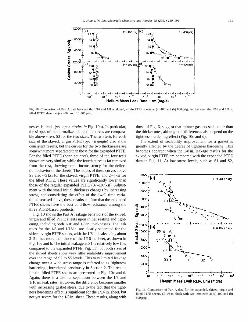
Fig. 10. Comparison of Part A data between the 1/16 and 1/8 in. skived, virgin PTFE sheets at (a) 400 and (b) 800 psig, and between the 1/16 and 1/8 in.filled PTFE sheet, at (c) 400, and (d) 800 psig.
nesses is small (see open circles inFig. 10b). In particular,the s1opes of the normalized deflection curves are compara-ble above stress S3 for the two sizes. The two tests for eachsize of the skived, virgin PTFE (open triangle) also showconsistent results, but the curves for the two thicknesses aresomewhat more separated than those for the expanded PTFE.For the filled PTFE (open squares), three of the four testsshown are very similar, while the fourth curve is far removedfrom the rest, showing some inconsistency for the deflec-tion behavior of the sheets. The slopes of these curves aboveS3 are:∼3 ksi for the skived, virgin PTFE, and 2–4 ksi forthe filled PTFE. These values are significantly lower thanthose of the regular expanded PTFE (87–107 ksi). Adjust-ment with the small initial thickness changes by increasingstress, and considering the effect of the dwell time varia-tion discussed above, these results confirm that the expandedPTFE sheets have the best cold-flow resistance among thethree PTFE-based products.
Fig. 10 shows the Part A leakage behaviors of the skived,virgin and filled PTFE sheets upon initial seating and tight-ening, including both 1/16 and 1/8 in. thicknesses. The leakrates for the 1/8 and 1/16 in. are clearly separated for theskived, virgin PTFE sheets, with the 1/8 in. leaks being about2–5 times more than those of the 1/16 in. sheet, as shown inFig. 10a and b. The initial leakage at S1 is relatively low (i.e.compared to the expanded PTFE, Fig. 11), but both sizes ofthe skived sheets show very little sealability improvementover the range of S2 to S5 levels. This very limited leakagechange over a wide stress range is referred to as ‘tightnesshardening’, introduced previously in Section 2. The resultsfor the filled PTFE sheets are presented in Fig. 10c and d.Again, there is a distinct separation between the 1/8 and1/16 in. leak rates. However, the difference becomes smallerwith increasing gasket stress, due to the fact that the tight-ness hardening effect is significant for the 1/16 in. sheet, butnot yet severe for the 1/8 in. sheet. These results, along with
those of Fig. 6, suggest that thinner gaskets seal better thanthe thicker ones, although the differences also depend on thetightness hardening effect (Fig. 10c and d).
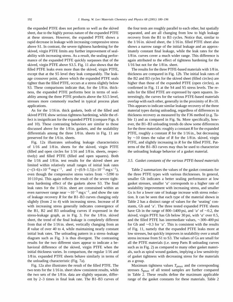
The extent of sealability improvement for a gasket isgreatly affected by the degree of tightness hardening. Thisbecomes apparent when the 1/8 in. leakage results for theskived, virgin PTFE are compared with the expanded PTFEdata in Fig. 11. At low stress levels, such as S1 and S2,
Fig. 11. Comparison of Part A data for the expanded, skived, virgin andfilled PTFE sheets, all 1/8 in. thick with two tests each at (a) 400 and (b)800 psig.
192 J. Huang, W. Lee / Materials Chemistry and Physics 68 (2001) 180–196
the expanded PTFE does not perform so well as the skivedsheet, due to the highly porous nature of the expanded PTFEat these stresses. However, the expanded PTFE shows arapid decrease in leakage with increasing compressive stressabove S1. In contrast, the severe tightness hardening for theskived, virgin PTFE limits any further improvement of seal-ability with increasing stress. As a result, the sealing perfor-mance of the expanded PTFE quickly surpasses that of theskived, virgin PTFE above S3.5. Fig. 11 also shows that thefilled PTFE leaks even more than the skived, virgin PTFE,except that at the S5 level they leak comparably. The leak-age crossover point, above which the expanded PTFE sealstighter than the filled PTFE, occurs at a stress slightly belowS3. These comparisons indicate that, for the 1/8 in. thick-ness, the expanded PTFE performs best in terms of seal-ablity among the three PTFE products above the S3.5 level,stresses more commonly reached in typical process plantapplications.
As for the 1/16 in. thick gaskets, both of the filled andskived PTFE show serious tightness hardening, while the ef-fect is insignificant for the expanded PTFE (compare Figs. 6and 10). These contrasting behaviors are similar to thosediscussed above for the 1/8 in. gaskets, and the sealabilitydifferentials among the three 1/8 in. sheets in Fig. 11 arepreserved for the 1/6 in. sheets.
Fig. 12a illustrates unloading leakage characteristicsof 1/16 and 1/8 in. sheets for the skived, virgin PTFE(filled and open circles for 1/16 and 1/8 in. sheets, respec-tively) and filled PTFE (filled and open squares). Boththe 1/16 and 1/8 in. test results for the skived sheet arelimited within relatively small ranges of initial leak rates(∼(3–6)×10−6 mg s−1, and (∼(0.9–1.5))×10−5 mg s−1),even though the compressive stress varies from∼5390 to10 110 psi. This again reflects the result of the severe tight-ness hardening effect of the gaskets above S3. The finalleak rates for the 1/16 in. sheet are constrained within aneven narrower range near∼10−5 mg s−1, and show the rateof leakage recoveryR for the B1–B3 curves changing onlyslightly (from 2 to 4) with increasing stress. Increase ofRwith increasing stress generally indicates convergence ofthe B1, B2 and B3 unloading curves if expressed in thestress-leakage graph, as in Fig. 3. For the 1/8 in. skivedsheet, the trend of the final leakage is completely differentfrom that of the 1/16 in. sheet, vertically changing from anR value of over 40 to 4, while maintaining nearly constantinitial leak rates. The unloading pattern in a stress–leakagediagram such as Fig. 3 is thus divergent. The contrastingresults for the two different sizes appear to indicate a be-havioral difference of the skived, virgin PTFE when theinitial thickness varies. In comparison, the regular 1/16 and1/8 in. expanded PTFE sheets behave similarly in terms ofthe unloading characteristic (Fig. 7a).
Fig. 12a also illustrates the result of the filled PTFE. Thetwo tests for the 1/16 in. sheet show consistent results, whilethe two sets of the 1/8 in. data are slightly separate, differ-ent by 2–3 times in final leak rate. The B1–B3 curves of
the four tests are roughly parallel to each other, but spatiallyseparated, and are all changing from low to high leakagerecovery from the B1 to B3 cycles. Notice that, similar tothe 1/16 in. skived sheet, the 1/16 in. filled PTFE sheet alsoshows a narrow range of the initial leakage and an approx-imately constant final leakage, while the leak rates for the1/8 in. curves cover a much wider range. This difference isagain attributed to the effect of tightness hardening for the1/16 but not for the 1/8 in. sheet.
The results for the three PTFE-based materials with 1/8 in.thickness are compared in Fig. 12b. The initial leak rates ofthe B2 and B3 cycles for the skived sheet (filled circles) arehigher than those of the expanded PTFE (open circles), asconfirmed in Fig. 11 at the S4 and S5 stress levels. The re-sults for the filled PTFE are expressed by open squares. In-terestingly, the curves for the various PTFE-based materialsoverlap with each other, generally in the proximity ofR=10.This appears to indicate similar leakage recovery of the threematerial types during unloading, regardless of differences inthickness recovery as measured by the F36 method (e.g. Ta-ble 1) and as compared in Fig. 9a. More specifically, how-ever, the B1–B3 unloading trends do show some differencesfor the three materials: roughly a constantR for the expandedPTFE, roughly a constantR for the 1/16 in., but decreasingby ∼10 times the value ofR for the 1/8 in. skived, virginPTFE, and slightly increasing inR for the filled PTFE. Pat-terns of the B1–B3 curves may thus be used to characterizethe unloading leakage behavior of a gasket material.
3.5. Gasket constants of the various PTFE-based materials
Table 2 summarizes the values of the gasket constants forthe three PTFE types with various thicknesses. In general,smaller Gb indicates a better sealing performance at lowgasket stresses, smaller ‘a’ corresponds to a higher rate ofsealability improvement with increasing stress, and smallerGs is for a lower rate of leakage increase with stress reduc-tion. It can be seen that each type of the material shown inTable 2 has a distinct range of values for the ‘seating’ con-stants, Gb and ‘a’. The three tested expanded PTFE sheetshave Gb in the range of 800–1400 psi, and ‘a’ of ∼0.2, theskived, virgin PTFE has Gb below 30 psi, with ‘a’ over 0.5,and the filled PTFE has intermediate values,∼300–400 psifor Gb and∼0.3 for ‘a’. This is consistent with the resultsof Fig. 11, namely that the expanded PTFE leaks more atlow stresses, but quickly improves in sealability over a smallstress increase from S1 to S3. The values of Gs are small forall the PTFE materials (i.e. steep Parts B unloading curvessuch as in Fig. 2) as compared to many other gasket materi-als, such as spiral wound gaskets, implying a low sensitivityof gasket tightness with decreasing stress for the materialsas a group.
Maximum tightness valuesTpmax and the correspondingstressesSgmax of all tested samples are further comparedin Table 2. These results define the maximum applicablerange of the gasket constants for these materials. Table 2
J. Huang, W. Lee / Materials Chemistry and Physics 68 (2001) 180–196 193
Fig. 12. (a) Parts B data expressed as initial leak rate vs. the final leak rate for both 1/16 and 1/8 in. thick skived, virgin and filled PTFE sheets withtwo tests each. (b) Comparison of Parts B data among the expanded, virgin and filled PTFE in l/8 in. thickness.
shows that the expanded PTFE can reach higher tightnesslevels within the ROTT stress limit, consistent with the find-ing from Fig. 11 at the S5 level. TheSgmax values for boththe skived, virgin PTFE sheets and the 1/16 in. filled PTFEsheet are significantly lower than the actual S5 level (i.e.10 110 psi), reflecting the effect of serious tightness harden-ing on these materials.
Notice that the values of Gs for the three expanded PTFEsheets are narrowly defined, while the values between the1/16 and 1/8 in. sheets of the skived, virgin PTFE, and of thefilled PTFE, are very different. The order of magnitude dif-ference in Gs appears to indicate drastically different unload-ing behaviors between the two thicknesses of a material, butas shown in Fig. 12a, the unloading properties as expressedby leakage recovery of a material are actually comparablefrom one thickness to the other. The use of Gs for express-ing unloading characteristics thus requires special caution.
3.6. Relationship between micro-structure and mechanicalproperties of PTFE-based gasket materials
It has been demonstrated that the mechanical propertiesof the expanded PTFE as shown in Fig. 9 are far differentfrom those of the other two types of PTFE-based materi-als in that the expanded product is much more compress-ible, and creeps least in terms of plateau lengths or slopesof normalized deflection curves. In other words, upon load-ing, the expanded PTFE is quickly compressed to position,and roughly stays in place even with additional compres-sion to 10 110 psi, while the other two material types con-tinue to lose thickness during the course of a test. We at-tribute these different features to the differences in terms ofmicro-structures of the materials.
Fig. 13a shows that the expanded PTFE contains manynodes, interconnecting fibrils, and micro-pores. It is thisporous structure which contributes to the low density of theexpanded PTFE (Table 1), softness, high compressibility,and low thickness recovery. Good surface conformability of
the expanded PTFE is achieved by a combination of thehigh compressibility, and the ability of these fibrils to fill inflange irregularities. In addition, as constrained by its molec-ular structure, PTFE has the tendency to elongate and fibril-late under stretching along the directions of carbon–carbonbackbones, thus reducing dimensional stability. A quick ex-pansion process is likely to lock the PTFE material into ameta-stable, fibrous state which then will not be easily af-fected by additional tension. The strength of PTFE is, there-fore, enhanced significantly through the creation of theseinterconnecting fibrils.
In contrast, as shown in Fig. 13b, there is no internal struc-ture visible for the skived, virgin PTFE. The low strength ofthe material is thus inherited from the raw PTFE powders,from which a skived sheet is produced, where the molecularforces between individual grains are weak.
With the addition of fillers, as shown in Fig. 13c, the creepresistance of PTFE materials become slightly better, but theprocesses involved in producing filled PTFE do not reallychange the basic properties of PTFE [3]. As a result, both thePTFE types show lower material strength, and a tendency ofcontinuing to ‘flow’ under constant compression (i.e. highcreeping), as compared to the expanded PTFE. Also, theyare harder, and less compressible.
The unique mechanical and sealing characteristics of anexpanded PTFE sheet, to be illustrated by ROTT test data,result from its micro-structure generated by the isotropicexpansion process. The typical micro-structure of the ex-panded PTFE sheets is presented in Fig. 13a, a scanningelectron microscopic (SEM) image. The structure comprisesa large quantity of nodes interconnected by micro-fibrils(light-colored areas). The dark areas indicate the pore spacewith no PTFE material present. In contrast, there is not muchinternal structure for the skived, virgin PTFE, as shown inFig. 13b by the uniform color of the image. Fig. 13c forthe filled PTFE material reveals a mixture of barium sulfatefillers (bright) and PTFE matrix (light gray). Again, thereis no visible internal structure for the PTFE portion of the
194 J. Huang, W. Lee / Materials Chemistry and Physics 68 (2001) 180–196
Fig. 13. Scanning electron photomicro-graph of (a) expanded PTFE (b) skived, virgin PTFF and (c) filled PTFE with barium sulfate fillers.
material, and no bonding between the two components isexpected.
3.7. Selection of gaskets based on ROTT test results
There have been extensive publications dealing with prop-erties and functions of gasket materials, gasket selection cri-teria, and design and behavior of gasketed joints (see, e.g.Refs. [13,14], and references therein). The ROTT test resultspresented so far confirm that the method can also be used toeffectively characterize and quantify the performance differ-ences of the PTFE-based gaskets. The knowledge, in turn,will help identification and selection of the proper gasket fora specific process application.
In general, a high-creeping material is always less favor-able than a low-creeping one, due to the constant need forfield maintenance personnel to re-torque the gasket in orderto maintain the desired gasket stress and leakage level. Thecold-flow/creep resistance of a material can be properly ex-pressed by the ROTT deflection results (i.e. Fig. 9).
The required compressive stress to seal also plays a ma-jor role for gasket selection. For example, many process ap-
plications require torque values corresponding to a gasketstress near or above S4. The leakage test results compared inFig. 11 show that the expanded PTFE seals tightest amongthe three materials shown, and it may be the best candidatefor these high-load applications. In addition to the sealabil-ity difference, the filled and skived PTFE sheets are hard,and may damage the flange surface under high compression.
For some other applications requiring low bolt loads toavoid cracking of the flange and piping systems during jointtightening, these may be in the range where the filled PTFEand skived, virgin PTFE seal tighter, provided that the flangesurfaces are at a near-perfect condition similar to that inthe ROTT tests. However, many real-life flanges are imper-fect, and the flange irregularities may not be properly ac-commodated by the hard and less compressible materials.A newly designed low-torque gasket incorporating the ex-panded PTFE sheet and a proprietary PTFE diaphragm ma-terial can properly address the issues associated with suchlow torque requirements. The design utilizes upper and lowerring gaskets with a reduced contacting area, attached to thehigh-density (>1.5 g cm−3) diaphragm sheet acting as a gas-ket carrier. The expanded PTFE rings serve for the major
J. Huang, W. Lee / Materials Chemistry and Physics 68 (2001) 180–196 195
sealing function, and with the reduced surface area, a highgasket stress in the range for good sealability of the materialcan be achieved even if the torque remains low. The perme-ation through the diaphragm sheet is expected to be smallbecause of the high density, and hence low porosity, of thesheet. The new gasket design has been used to solve formany problems of low-torque applications, and is expectedto receive wider acceptance from the related industries.
Thickness requirement is another factor to consider ingasket selection. Conventional wisdom says that ‘thinneris better’, because a thinner gasket normally has betterbolt-load retention, higher blow-out resistance, and smallerpassage for permeation which should lead to a lower leakrate. Comparison of the ROTT test results in Figs. 6 and 10for the 1/16 and 1/8 in. sheets of various PTFE gaskets con-firms a slightly tighter seal for the thinner gaskets, althoughthe difference is not significant. It may be preferable to usea thinner gasket if the surface condition allows. However,for uneven/waving surfaces or delicate flange materials (e.g.glass-lined pipes), a thicker gasket may be necessary.
As mentioned previously, for some difficult installationconditions, the regular expanded PTFE sheet may be toosoft to be handled easily. A remedy to this is to use the rigidexpanded PTFE sheet instead. The filled PTFE and skived,virgin PTFE sheets may also be used because of their highrigidity. However, the better sealing performance (compareFigs. 6 and 11) combined with the better mechanical char-acteristics (compare Figs. 5 and 9) make the rigid expandedPTFE sheet a better choice for these application conditions.
The above examples illustrate how the ROTT test resultscan be used as gasket selection criteria, considering variouscircumstances. It is worth noting that other criteria may en-ter to influence the gasket selection for an application. Forexample, it is important to know the applicable temperaturerange of a gasket and its high-temperature mechanical andsealing behaviors. This requires information characterizedfrom elevated temperature tests other than the ROTT test [6],which only measures room temperature properties. Chem-ical compatibility is another factor to consider. The filledPTFE has a reduced chemical compatibility compared to theskived, virgin PTFE and expanded PTFE, affected by thechemical properties of the added fillers. Examples of theseand other factors have been documented elsewhere [13,14].
3.8. Use of gasket constants for comparing gasket sealingperformances
It is a common practice that gasket manufacturers com-pare a gasket constant of one material to the correspond-ing value of another, and attempts to draw conclusions onthe performance differences of the two. Favorable propertiesof each constant have been summarized previously, namelylower Gb, lower ‘a’ and lower Gs. However, no single gas-ket constant can represent the complete sealing propertiesof a gasket, and instead a combination of the three shouldbe used to evaluate the overall performance of a gasket.
The applicable limit of the gasket constants for a gasketshould also be emphasized. For example, the assembly linebelow a knee of Part A tightness data may be deviated fromthe actual data (Fig. 2), and the use of gasket constants atthese stresses will tend to underestimate the performancelevel of the gasket. For materials showing a severe tight-ness hardening effect, the usable range of the assembly lineis much reduced (Table 2). Comparison of the sealabilityamong a variety of gaskets above these limits is unlikelyto provide an accurate assessment of the true performancedifferences.
4. Conclusions
1. PVRC and ROTT tests provide critical information onsealing performance and mechanical behavior of a gasketmaterial through the helium mass leak rate and gasketdeflection measurements.
2. Three expanded PTFE sheet samples produced by anisotropic expansion process were investigated by theROTT tests: regular sheets of 1/16 and 1/8 in. thick (den-sity 0.85 g cm−3), and rigid sheet of l/8 in. thick (density1.2 g cm−3). The results from the two tests of each sam-ple are fairly consistent. In addition, all three gasketsshow similar leakage and deflection behaviors, with mi-nor variations. The general pattern of helium mass leakrates for the expanded PTFE includes a rapid increase insealability between 1025 and 5390 psi gasket stress, andsmaller but steady improvement above that. The leakagerecovery for the Parts B unloading sequences is in theproximity of 10, meaning roughly 10 times of leakageincrease during gasket decompression to 1025 psi.
3. The 1/16 in. sheet seals better than the 1/8 in. by about2–4 times, consistent with the conventional wisdom that‘thinner is better’. The regular and rigid 1/8 in. sheetsshow comparable leakage results.
4. The deflection results confirm high compressibility, lowrecovery and excellent creep resistance of the expandedPTFE. The normalized deflection values are comparablebetween the regular 1/16 and 1/8 in. sheets, but lower forthe rigid sheet due to its higher density, and lower overallcompressibility. The slope of the normalized deflectioncurve for the regular sheets is steeper than that for therigid sheet, implying a slightly better cold-flow resistancefor the regular sheets.
5. The ROTT test results of the expanded PTFE sheets arecompared with the data of skived, virgin PTFE and filledPTFE sheets. The comparison shows that the expandedPTFE seals best and creeps least above the stress level atS3.5 (∼6500 psi). The leak rates of the expanded PTFEshow only insignificant tightness hardening phenomenon,while the effect greatly limits the sealing performance ofthe skived, virgin PTFE and filled PTFE at high com-pressive loads. In addition, the deflection results indicatethat the expanded PTFE has the best cold-flow resistance
196 J. Huang, W. Lee / Materials Chemistry and Physics 68 (2001) 180–196
among the three tested PTFE-based materials. Also, thesealing and mechanical behaviors of the skived, virginPTFE and filled PTFE are less consistent than those ofthe expanded PTFE in terms of test-to-test and thicknessvariations.
6. The excellent mechanical properties of the expandedPTFE result from its porous microstructure comprising alarge quantity of nodes and micro-fibrils. In contrast, theother two materials are lacking in strong internal struc-tures to prevent constant creeping under compression.
7. The ROTT test results presented here can be used asgasket selection criteria, based on specific conditions re-quired by a process application, such as sealability, creepresistance, thickness, and flange surface conditions. How-ever, it requires further tests at elevated temperatures inorder to characterize high temperature performances ofgaskets. Other factors such as chemical compatibility ofa gasket with process fluids should also be considered.
8. Gasket constants derived from the ROTT tests can pro-vide a useful guideline for bolted-joint design rules. How-ever, one should be cautious about the applicable rangewithin which the resultant design lines can closely rep-resent the actual data. Although the design lines may beused to compare gasket sealability, it may be better to usethe actual tightness data, not the calculated design lines,to assess sealing performances of gaskets.
References
[1] R.J. Plunkett, US patent 2,230,654 (1941).
[2] R.W. Gore, Process for producing porous products. US patent3,953,566 (1976).
[3] J. Latte, D. Coomber, Industrial gaskets. In: J.H. Bickford, (Ed.),Gaskets and Gasketed Joints, Marcel Dekker, New York, 1997, pp.87–122.
[4] M. Derenne, J.R. Payne, A. Bouzid, L. Marchand, Proposedmodifications to Draft No. 9 of the standard test method for gasketconstants for bolted joint design. Technical Symposium of the FluidSealing Association, Nashville, TN, 1998.
[5] J.R. Payne, R.W. Schneider, ASME flanged joint rules — new vs.traditional. In: J.H. Bickford (Ed.), Gaskets and Gasketed Joints,Marcel Dekker, New York, 1997, pp. 423–485.
[6] M. Derenne, J.R. Payne, L. Marchand, A. Bazergui. PVRC/MTItechnology for characterizing gaskets used in bolted flangedconnections. In: J.H. Bickford, (Ed.), Gaskets and Gasketed Joints,Marcel Dekker, New York, 1997, pp. 137–302.
[8] M. Derenne, J.R. Payne, Guide to the PVRC ROTT test. PVRCProject, TTRL, Ecole Polytechnique, University of Montreal, 1998.
[9] A.C. Guizzo, Determination of design gasket assembly stress withthe new constants — exact method. Technical Symposium of theFluid Sealing Association, 1996, pp. 218–233.
[10] J. Latte, Questions to the feasibility of the new design gasketconstants Gb,a, Gs. Technical Symposium of the Fluid SealingAssociation, Nashville, TN, 1998.
[11] W. Lee, J. Huang, Investigating flow behavior in expanded PTFEgasket sheets under high gasket stresses. ASME Pressure Vessel andPiping Conference, 2000.
[12] W. Lee, J. Huang, New interpretation and formulation of the PVRCroom temperature tightness test data of gasket materials, ASMEPressure Vessels and Piping Conference, Vol. 368, 1999, pp. 55–62.
[13] D.E. Czernik, Gaskets — Design, Selection, and Testing,McGraw–Hill, New York, 1996.