Page 1
Sealing Characteristics of Tie Pads on Concrete Crossties
Proceedings of the 2010 Annual AREMA Conference
John C. Zeman, J. Riley Edwards1, David A. Lange, and Christopher P. L. Barkan
Department of Civil and Environmental Engineering
University of Illinois at Urbana-Champaign
205 N. Mathews Ave., Urbana, IL 61801
Fax: (217) 333-1924
5,441 Words, 3 Tables, 3 Figures
John C. Zeman J. Riley Edwards David A. Lange Christopher P.L. Barkan
(217) 377-7714 (217) 244-7417 (217) 333-4816 (217) 244-6338
[email protected] [email protected] [email protected] [email protected]
1 Corresponding author
Page 2
ABSTRACT
The sealing characteristics of tie pads on concrete-tie rail seats directly influence the intrusion of moisture
and fines, which are two of the four primary causes of concrete-tie rail seat deterioration (RSD). The
amount of leakage allowed by the tie-pad seal also determines the response of rail-seat surface water to
wheel loads. A laboratory test apparatus and procedure were developed and implemented to measure the
surface water pressure caused by applying normal loads to different tie pads. The measured surface water
pressures were also used to estimate the potential velocity of water at the pad-rail seat interface. Results
from the laboratory tests suggest that an effective tie-pad seal causes the surface water to become
pressurized under load, whereas an ineffective tie-pad seal allows the surface water to flow under load.
Pressurization may lead to hydraulic pressure cracking of the rail seat, while high-velocity flow may lead
to hydro-abrasive erosion of the rail seat. Relevant sealing characteristics of the tie pad or assembly
include the bulk flexural rigidity; the hardness, elasticity, roughness, geometry, and durability of the
surfaces at the tie pad-rail seat interface; the contact stress at rest (resulting from the clip toe load); and
the contact stress under load (resulting from the wheel load). Further research is needed to understand
which RSD mechanisms cause the most damage in the field and, therefore, should govern tie-pad design.
Page 3
INTRODUCTION
Rail seat deterioration (RSD) is degradation underneath the rail on a concrete tie. RSD loosens the
fastening system’s hold on the rail and often causes problems with cant and gauge which have been
known to cause derailments (1). RSD was first identified by North American railroads in the late-1980’s
(T. Johns, unpublished 2009). In the early-1990’s, tests were conducted at the Transportation Technology
Center’s (TTC’s) Facility for Accelerated Service Testing (FAST) to compare the resistance of different
combinations of concrete ties and fastening system components to RSD (2). TTC’s tests resulted in the
identification of certain tie pads and pad assemblies that mitigated RSD to a manageable level, providing
solutions which were sufficient for the North American freight loading conditions in the mid-1990’s.
Since then, rail life has increased due to improved materials and maintenance practices. In
addition, axle loads have increased. Consequently, the materials and designs that worked in the past to
mitigate RSD are often inadequate today (R. Reiff, unpublished 2009). This observation was confirmed
by the results of a 2008 industry survey which identified RSD as the most critical problem with respect to
concrete tie use on North American freight railroads (1). In response to the continued prevalence of RSD
on primary freight corridors in North America, members of the American Railway Engineering and
Maintenance-of-Way Association (AREMA) Committee 30 (Ties) recently formed a working group of
railroad employees, suppliers, and researchers to address the problem. One of the first actions of this
working group was to agree on the causes of RSD (Tables 1 and 2). These tables summarize the current
industry understanding of RSD.
TABLE 1. Relevance of the Causes of RSD to
the Potential Concrete Deterioration Mechanisms
Causes Abrasion Crushing Freeze-
Thaw
Hydraulic
Pressure
Hydro-
Abrasive
High stresses at rail seat ���� ���� ���� ����
Relative motion at rail seat ���� ���� ���� ����
Presence of moisture ���� ���� ���� ���� ����
Presence of abrasive fines ���� ����
Page 4
TABLE 2. Summary of Factors, Internal and External to
the Concrete Tie, Related to the Causes of RSD
High Stresses
at the Rail Seat
Relative Motion
at the Rail Seat
Presence of
Moisture
Presence of
Abrasive Fines
Inte
rnal Fact
ors
Loss of proper rail cant
• Loss of material at
rail seat
• Loss of material at
shoulder
• Loss of toe load
Looseness of fastening
system (loss of toe load)
• Loss of material at
rail seat
• Loss of material at
shoulder
• Yielded or fractured clips
Scrubbing action
• Poisson’s ratio of tie pad
Tie pad seal
• Material properties
and surface geometry
of tie pad
• Looseness of fastening system
• Wear of rail seat and
tie pad
Concrete saturation
• Permeability of
concrete and rail seat
surface
Tie pad seal
• Material properties
and surface geometry
of tie pad
• Looseness of fastening system
• Wear of rail seat and
tie pad
Fines from wear of rail
seat components
Exte
rnal Fact
ors
High vertical loads
• Impact loads
• Degraded track geometry
High L/V ratio
• Truck hunting • Over-/under-balanced speeds on curves
• Sharp curves • Degraded track geometry
High longitudinal loads
• Steep grades • Thermal stresses
in rail
• Train braking and locomotive traction
Poor load distribution
among adjacent ties
• Non-uniform
track substructure
• Non-uniform
tie spacing
• Degraded track geometry
Uplift action
• Low stiffness of track substructure,
higher deflections
Lateral action
• Truck hunting • Truck steering around curves (push and pull)
• Over-/under-balanced speeds on curves
• Sharp curves Longitudinal action
• Steep grades • Thermal stresses
in rail
• Train braking and locomotive traction
Climate
• Average annual rainfall, days with
precipitation,
humidity, etc.
• Average evaporation rate, etc.
• Extreme daily or
annual temperatures
• Number of annual
freeze/thaw cycles
Environment
• Wind-blown sand
or dust
• Moisture to transport
the abrasive fines
under the tie pad
Track maintenance
• Ground ballast • Metal shavings from
rail grinding
Train operations
• Application of locomotive sand for
braking (especially
on grades)
• Coal dust and other abrasive commodities
Table 2 separates the factors that contribute to the causes of RSD into both internal and external
factors. Some factors are within the realm of concrete-tie design and others are functions of track
alignment, track maintenance, train operations, or the climate/environment. Comparing Tables 1 and 2
Page 5
highlights the fact that RSD is a complex interaction of different deterioration mechanisms and causes.
The focus of this paper is one aspect of concrete-tie design that relates to the causes and mechanisms of
RSD: the sealing characteristics of tie pads. The tie-pad seal is important because its design directly
influences the potential for intrusion of moisture and fines beneath the tie pad and the potential for
hydraulic pressure cracking or hydro-abrasive erosion to damage the concrete at the rail seat (3).
CURRENT DESIGN CRITERIA FOR TIE PADS
Tie pads are thermoplastic materials or assemblies of different materials placed between the rail base and
the rail seat on the concrete tie. For “severe service” applications, the AREMA Manual for Railway
Engineering recommends using three-part or two-part pads, or “reinforced elastomer one-piece pads” (4).
It is also noted that very hard tie pads have previously caused problems with abrasion, and these should
be avoided (4). Tie pads provide many functions including stress distribution among adjacent rail seats,
abrasion resistance, and impact attenuation / damping. AREMA notes these functions and also
recommends that tie pads fulfill a sealing function to “minimize water intrusion” (4) but does not provide
guidance on how to design or select a tie pad with optimal sealing characteristics.
AREMA recommends multiple quality control tests for tie-pad materials. Material properties
such as compression set, hardness, Vicat softening temperature, tear resistance, abrasion resistance, and
rubber properties in compression and shear may relate to the sealing capabilities of a thermoplastic pad
(4). Test 4A in Section 2.5.1 of AREMA Chapter 30 describes the procedure for obtaining the bulk
compressive stiffness (i.e. “spring rate”) of a tie pad or assembly (4). Generally, the sealing capability of
a tie pad or assembly will depend not just on the individual material properties but also on the bulk
characteristics of the pad or assembly. In particular, the characteristics of the tie pad-rail seat interface
(including the surface geometry of the pad), the hardness of the tie pad compared with that of the rail seat,
and the roughness of each surface will influence the sealing capability. Such interfacial characteristics are
not currently addressed in AREMA Chapter 30.
Page 6
HYDRAULIC PRESSURE AND FLOW AT THE RAIL SEAT
Water may enter the pad-concrete interface through several mechanisms and paths: precipitation may
enter directly between the pad and rail seat via tiny gaps and irregularities, it may enter if loading and
uplift occur during or after precipitation, or the concrete may become saturated, allowing water to enter
the interface by diffusion or by suction during a load cycle, thus drawing water up from the concrete
pores. The intrusion of water over the surface of the rail seat may also transport abrasive fines, which can
contribute to abrasion (1).
To study how the surface water at the rail seat might respond to a normal force, two ideal
scenarios are considered. The first assumes that the tie pad creates a perfect seal on the rail seat and the
concrete is impermeable - such that all of the normal force from a wheel load is converted to pressure in
the water. In this ideal case, the water pressure would be the load, P, divided by the rail seat area, A. In
the second case, the concrete is again considered impermeable, but there is no seal between the tie pad
and the rail seat. The water is accelerated by the wheel load and ejected from underneath the tie pad.
This assumes that water is an incompressible fluid, thus all the water must flow out of the tie pad-rail seat
interface rather than being pressurized.
Considering Bernoulli’s equation for pipe flow without losses, the energy in the water is divided
among the pressure energy and the velocity energy (5):
21
2Water Energy = p vρ+
(1)
Here, p is the pressure, v is the velocity, and ρ is the density of water (1000 kg/m3) (5). Theoretically,
the water energy would be, at most, the energy imparted by the normal stress on the rail seat:
212
Load EnergyP
p vA
ρ= ≅ + (2)
2 P
v pAρ
≅ − (3)
Page 7
Assuming that all of the load energy is transferred to the surface water at the rail seat, this derivation
represents the maximum surface water velocity. In reality, all of the load energy might not be transferred
through the water, particularly if the water is not evenly distributed over the rail seat. There will also be
energy losses to friction, heat, noise, and compression of the pad. Other factors such as the permeability
of the concrete, wetness of the pad surface, and volume losses to the outside, will also play a major role.
However, the Bernoulli equation, as presented here, illustrates the theoretical extremes for pressure and
velocity in the cases where there is (1) a perfect seal (v = 0), (2) no seal (p = 0), or (3) an imperfect seal (p
≠ 0, v ≠ 0). The third case is closest to reality, assuming that neither a perfect seal nor the complete
absence of a seal is possible in a concrete-tie rail seat.
Hydraulic Pressure Cracking and Hydro-Abrasive Erosion
As described above, water underneath the tie pad in a concrete-tie rail seat may be either pressurized or
caused to flow, depending on the sealing characteristics of the tie pad. It is possible that such hydraulic
actions could damage the concrete rail seat and contribute to RSD. Specifically, the pressurization of the
water could cause hydraulic pressure cracking, while water flow could cause hydro-abrasive erosion.
Hydraulic pressure cracking is microcracking that results when loads pressurize the surface water
at the rail seat and lead to damaging pore pressure (tensile stress) within the concrete (1). We modeled
the compressive stresses from rail seat loads, tie flexure, and precompression along with pore pressure in
saturated concrete. To estimate the damaging limits of pore pressure in concrete ties, we compared the
resulting net stress with the cracking resistance of the concrete (3, 6).
Here, concrete wear through the action of flowing water and suspended-particle abrasion is
referred to as hydro-abrasive erosion, though it is also found in the literature as abrasive erosion or
suspended-particle erosion. The parameters that influence the wear rate are flow velocity, angle of impact
relative to the concrete surface, exposure time, concentration of suspended particles, and particle size,
shape, and hardness (7, 8, 9).
Page 8
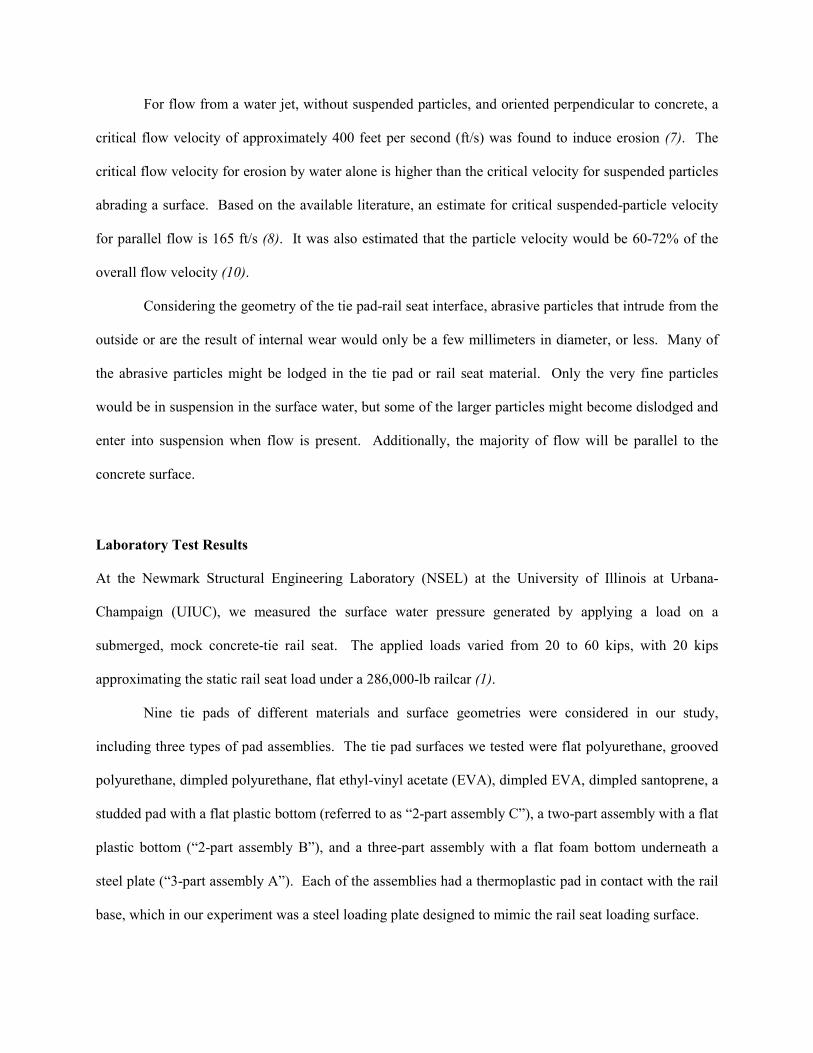
For flow from a water jet, without suspended particles, and oriented perpendicular to concrete, a
critical flow velocity of approximately 400 feet per second (ft/s) was found to induce erosion (7). The
critical flow velocity for erosion by water alone is higher than the critical velocity for suspended particles
abrading a surface. Based on the available literature, an estimate for critical suspended-particle velocity
for parallel flow is 165 ft/s (8). It was also estimated that the particle velocity would be 60-72% of the
overall flow velocity (10).
Considering the geometry of the tie pad-rail seat interface, abrasive particles that intrude from the
outside or are the result of internal wear would only be a few millimeters in diameter, or less. Many of
the abrasive particles might be lodged in the tie pad or rail seat material. Only the very fine particles
would be in suspension in the surface water, but some of the larger particles might become dislodged and
enter into suspension when flow is present. Additionally, the majority of flow will be parallel to the
concrete surface.
Laboratory Test Results
At the Newmark Structural Engineering Laboratory (NSEL) at the University of Illinois at Urbana-
Champaign (UIUC), we measured the surface water pressure generated by applying a load on a
submerged, mock concrete-tie rail seat. The applied loads varied from 20 to 60 kips, with 20 kips
approximating the static rail seat load under a 286,000-lb railcar (1).
Nine tie pads of different materials and surface geometries were considered in our study,
including three types of pad assemblies. The tie pad surfaces we tested were flat polyurethane, grooved
polyurethane, dimpled polyurethane, flat ethyl-vinyl acetate (EVA), dimpled EVA, dimpled santoprene, a
studded pad with a flat plastic bottom (referred to as “2-part assembly C”), a two-part assembly with a flat
plastic bottom (“2-part assembly B”), and a three-part assembly with a flat foam bottom underneath a
steel plate (“3-part assembly A”). Each of the assemblies had a thermoplastic pad in contact with the rail
base, which in our experiment was a steel loading plate designed to mimic the rail seat loading surface.
Page 9
After plotting the maximum surface pressure for each pad versus the applied load, it was
determined that all the tie pads could be grouped into one of three categories: flexible (flat and grooved
polyurethane, dimpled santoprene), semi-rigid (flat and dimpled EVA, dimpled polyurethane), or
assembly with a rigid layer (all three pad assemblies). The pads were placed in these categories solely by
their load-pressure behavior, and these names were assigned to the groups in an attempt to explain the
differences between them. The mean regression lines that fit the experimental data were plotted on the
same graph, sorted by these pad groups (Figure 1). For the case of a perfect seal, the surface pressure
would be equal to the load divided by the area of the rail seat, and this is plotted on Figure 1 for
comparison, labeled “uniform load stress”. The applied load ranged from 20 to 60 kips, so there was no
data for loads below 20 kips.
FIGURE 1. Comparing the Mean Load-Pressure Models and
the Uniform Load Stress on the Rail Seat
0
400
800
1,200
1,600
2,000
0 10 20 30 40 50 60
Maxim
um
Surf
ace
Pre
ssure
, p (psi
g)
Applied Load, P (kips)
Flexible Pads
Semi-rigid Pads
Pad Assemblies, Rigid Layer
Strength Limit
Fatigue Limit
Uniform
Load Stress
Page 10
The load-pressure model for the flexible pads is close to the ideal uniform load stress (Figure 1),
suggesting that the flexible pads created a nearly perfect seal. Allowing some of the water to escape or
flow rather than become pressurized may explain the difference between the flexible and semi-rigid pads.
These results suggest that some tie pads create more effective seals than others, explaining the difference
in load-pressure behavior. Comparing the pressure measurements with estimates for concrete damage
limits (labeled “strength limit” and “fatigue limit” in Figure 1), it appears that an approach for preventing
hydraulic pressure cracking is to use pad assemblies because they do not form effective seals under load.
The potential for water flow and hydro-abrasive erosion were estimated from our experimental
results. We applied the Bernoulli estimate for maximum surface water velocity (equation 3) to the mean
load-pressure models. The resulting estimates for water velocity were scaled down to 72% to estimate the
potential suspended-particle velocity (Figure 2). The smallest value of particle velocity in the literature
that was associated with concrete erosion was approximately 165 ft/s, and this was for flow parallel to the
surface, similar to the condition for flow underneath the tie pad. This critical particle velocity was also
plotted for comparison (Figure 2).
Page 11
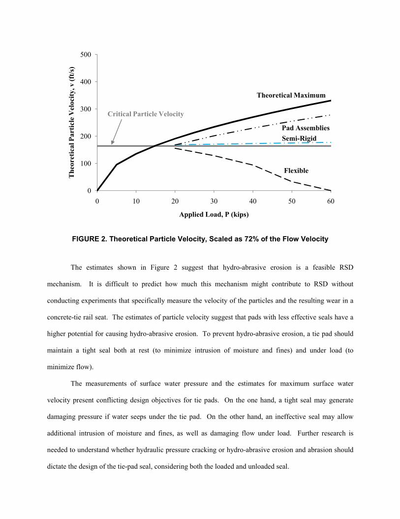
FIGURE 2. Theoretical Particle Velocity, Scaled as 72% of the Flow Velocity
The estimates shown in Figure 2 suggest that hydro-abrasive erosion is a feasible RSD
mechanism. It is difficult to predict how much this mechanism might contribute to RSD without
conducting experiments that specifically measure the velocity of the particles and the resulting wear in a
concrete-tie rail seat. The estimates of particle velocity suggest that pads with less effective seals have a
higher potential for causing hydro-abrasive erosion. To prevent hydro-abrasive erosion, a tie pad should
maintain a tight seal both at rest (to minimize intrusion of moisture and fines) and under load (to
minimize flow).
The measurements of surface water pressure and the estimates for maximum surface water
velocity present conflicting design objectives for tie pads. On the one hand, a tight seal may generate
damaging pressure if water seeps under the tie pad. On the other hand, an ineffective seal may allow
additional intrusion of moisture and fines, as well as damaging flow under load. Further research is
needed to understand whether hydraulic pressure cracking or hydro-abrasive erosion and abrasion should
dictate the design of the tie-pad seal, considering both the loaded and unloaded seal.
0
100
200
300
400
500
0 10 20 30 40 50 60
Theo
retica
l Part
icle
Vel
oci
ty, v (ft
/s)
Applied Load, P (kips)
Flexible
Semi-Rigid
Pad Assemblies
Critical Particle Velocity
Theoretical Maximum
Page 12
SEALING CHARACTERISTICS OF TIE PADS
In mechanical engineering terminology, tie pads are analogous to gaskets, though traditional gaskets are
typically used in environments much different than a concrete-tie rail seat under heavy haul freight
loading. Generally, a gasket’s seal increases as the compressive contact stresses (e.g. fastener toe load or
wheel load) increase. The leakage through the seal, in our case, is driven by a pressure gradient, and the
leakage increases as the pressure increases relative to the seal’s contact stress (11). One textbook on fluid
sealing lists the following as important characteristics of gasket seals: elasticity, surface roughness, wear
resistance, porosity, and surface geometry of the contacting surfaces; pressure, temperature, density,
vapor pressure, and viscosity of the fluid (11).
As with tie pads, gaskets are often layered composites of different materials. Generally, hard,
rigid contact surfaces require higher contact stresses to form the same seal as soft, elastic contact surfaces.
This is because the soft, elastic surfaces can more readily deform to block flow paths along the interface
(11). To create effective seals, it is recommended to maintain contact gasket stresses within a material-
specific usable stress range (11). Below this stress range, the gasket will not form an effective seal; above
this stress range, the gasket will be damaged. Elastomeric materials typically have two-part stress-strain
curves, with an initial strain-softening stage followed by an approximately linear, strain-hardening stage.
The minimum usable stress is the initiation of this linear, strain-hardening stage. The maximum usable
stress is a function of temperature (11). In mechanical engineering design, gaskets are selected for a
certain allowable leak rate at a given fluid pressure. For a given material, this allowable leak rate dictates
what preload is required (11). The above design concepts for gaskets could be applied to tie-pad design
in an effort to characterize and control the tie-pad seal. The following discussion considers empirical
observations of load-pressure behavior and measurements that may provide some insight into tie-pad
sealing characteristics.
Empirical Observations
While running a series of load-pressure tests, it was often observed that the loading plate would shift
position relative to the rail seat as a result of the flexibility of the test frame. If the loading plate-to-rail
Page 13
seat interface was mismatched, resulting in a nonzero contact angle, this reduced the seal at the interface
and significantly reduced the surface water pressure. Such a nonzero contact angle could result in the
field if the rail is rotated relative to the rail seat.
The grooved and flat polyurethane pad surfaces were two sides of the same tie pad. These
surfaces generated very similar load-pressure curves. The dimpled and flat EVA pads also generated
similar load-pressure curves, despite the difference in surface geometry, suggesting that isolated
indentations may not significantly change the load-pressure behavior. It is important to note that the
dimpled EVA and flat EVA are different pads with different thicknesses, providing a slightly different
comparison than between the grooved and flat polyurethane. Though the two EVA pads are nominally
the same material, there is room for variation of material properties to fit a specific product, similar to
how a concrete mix is adjusted to produce different strengths. The same can be said about the dimpled
and the flat polyurethane pads, which appear to have slightly different stiffness and hardness properties.
By using some simple tests (discussed in the following section), it was shown that the grooved
polyurethane pad has a relatively higher compressive stiffness and a lower flexural rigidity than the
dimpled polyurethane pad. The major difference between the dimpled santoprene and the dimpled
polyurethane pads is that the santoprene rubber was relatively flexible and compressible and underwent
permanent deformation after a few trials. These observations provide evidence that material properties of
the contacting pad determined what surface pressures were generated.
The studded pad (the top layer of the 2-part assembly C), which was the only pad to have narrow
channels running along its full length (providing openings at the pad boundaries), did not generate any
measurable pressure in any of its trials. The same results were observed when a dimpled pad and a
grooved pad were modified to provide 2-millimeter-wide channels from the indentation above the
measurement point to the pads’ edges. These observations suggest that providing direct flow paths along
the contact surface results in an effective absence of a seal under load.
Both the hardest contact surface – the plastic bottom of the two-part assemblies – and the softest
contact surface – the foam bottom of the three-part assembly – generated low load-pressure curves
Page 14
(Figure 1). For the plastic bottoms, it is possible that it was difficult to create a seal with a relatively hard,
stiff material, allowing water to flow rather than becoming pressurized. After one trial (applying up to
120 load cycles), the soft foam bottom would become permanently deformed. During the first trial, the
foam apparently created an adequate seal and developed pressure not too far below the semi-rigid pads.
When a subsequent trial was run with the same pad, a lower pressure was obtained, and even lower
pressures were generated with subsequent, higher loads. It may be that the deformation of the foam
destroyed its sealing capability and allowed the water to flow. Once the foam deformed and became an
ineffective seal, the pressure behavior of the three-part assembly was likely dictated by the hard, rigid
metal layer in the middle, which would not readily form a seal.
Measurements of Tie-Pad Characteristics
Simple, non-standard laboratory tests were conducted to measure the relative compressive and flexural
stiffness of the different tie pads and assemblies. The primary motivation was to identify properties of the
pads and assemblies that might explain their distinct load-pressure behaviors and sealing characteristics.
Each of the tie pads and assemblies were loaded in compression up to 50 kips, compressing the
pads between two 8.5-inch diameter plates. The actuator was advanced at a rate of 0.02-inch per minute.
The measurements were corrected for deflections of the test frame, and some example results are
presented here (Figure 3).
Page 15
FIGURE 3. Load-Deflection Results for Grooved Polyurethane Pad (Top Left),
Dimpled Polyurethane Pad (Top Right), 3-Part Assembly A (Bottom Left),
and 2-Part Assembly B (Bottom Right)
These curves typically had two distinct regions (strain-softening followed by strain-hardening),
and the slopes of these two regions, as well as the secant slope at 50 kips, are labeled (Figure 3). For
effective sealing at rest, the fastening system should apply a toe load that loads the pad or assembly well
into its strain-hardening stage. The original e-clip system had a rated toe load of 2.75 kips per clip (12),
-50
-40
-30
-20
-10
0
-0.10-0.08-0.06-0.04-0.020.00
Load, P (kip
s)
Deflection, d (in)
Kt2 = 4,534 k/in
Ks = 2,024 k/in
-50
-40
-30
-20
-10
0
-0.10-0.08-0.06-0.04-0.020.00
Load, P (kip
s)
Deflection, d (in)
Kt1 = 382 k/in
Kt2 = 2,800 k/in
Ks = 1,024 k/in
-50
-40
-30
-20
-10
0
-0.10-0.08-0.06-0.04-0.020.00
Load, P (kip
s)
Deflection, d (in)
Kt1 = 33 k/in
Kt2 = 3,174 k/in
Ks = 526 k/in
-50
-40
-30
-20
-10
0
-0.10-0.08-0.06-0.04-0.020.00
Load, P (kip
s)
Deflection, d (in)
Kt2 = 1,994 k/in
Ks = 1,817 k/in
Page 16
while the first Safelok system had a rated toe load of 4.5 to 5.6 kips per clip (13). Therefore, the load on
the rail seat at rest could be approximately 5 to 10 kips, depending on the system in use. Nominally, these
fastening systems have toe loads near or just above the transition between strain-softening and strain-
hardening behavior. The toe load tends to decrease over the life of the clips, due to plastic deformation of
the clips or reduction of clip deflection due to loss of the materials at the rail seat – wear of the pad, the
concrete, or the insulators. In this way, the design and durability of the fastening system will greatly
influence tie-pad sealing.
To convert the load-deflection slope to a compressive stiffness that is similar to a Young’s
modulus, the engineering strain was approximated as the tie-pad deflection over the initial thickness and
the normal stress was approximated as the load over the contact area between the pad and the test frame’s
8.5-inch diameter steel plates. The thickness was defined as the external thickness, not accounting for the
reduced thickness at indentations. The contact area was estimated by using a computer-aided drafting
program to calculate the intersection between the two areas, neglecting the loss of contact area due to the
indentations. Thus, the compressive stiffness is:
pad
eng contact
tP
A
σε δ
= (4)
For a simple test to estimate the flexural stiffness of the tie pads and assemblies, a 4.1-lb weight
was attached to the end of a pad/assembly which was fixed to a table’s edge, with a cantilever length of 5
inches. Because the moment of inertia of the pads was not easy to estimate, the flexural rigidity, EI, of
the tie pads and assemblies was estimated by rearranging the deflection (Δ) of a cantilever beam under a
point load (14):
3
3
PLEI =
∆ (5)
The second tangent stiffness (based on the strain-hardening slope), cantilever rigidity, and the
spring rate, calculated according to the AREMA Manual (4), were determined for each tie pad or
assembly (Table 3). The slopes shown in Figure 3 were not defined according to the AREMA Manual’s
Page 17
method, so they are not equal to the spring rate. It appears that the relative cantilever rigidity of the pads
aligns with the three load-pressure groups. There was no apparent relationship between the compressive
stiffness of the pad or assembly and the load-pressure behavior. However, other factors that contribute to
the contact surface’s ability to seal water are hardness, roughness, and surface geometry. These are
properties of just the contact surface, rather than the full pad/assembly. They were not quantified in our
study.
TABLE 3. Comparison of Tie-Pad Characteristics with the
the Load-Pressure Relationships
Load-Pressure Group Tie Pad
AREMA
Spring Rate
(k/in)
2nd
Tangent
Stiffness
(ksi)
Cantilever
Rigidity
(lb-in2)
Flexible Dimpled Santoprene 2,031 11.8 65
Grooved Polyurethane 4,324 30.6 76
Semi-Rigid Flat EVA 14,957 64.3 78
Dimpled EVA 2,355 17.7 85
Dimpled Polyurethane 3,461 20.2 94
Assemblies, Rigid Layer 2-Part Assembly B 1,757 18.6 114
2-Part Assembly C 3,297 31.3 304
3-Part Assembly A 3,219 24.0 2,733
As an example of the distinction between compressive stiffness and flexural rigidity, 3-part
assembly A has the lowest secant stiffness and one of the lowest second tangent stiffness, but it has the
highest cantilever rigidity by an order of magnitude. For an assembly of different materials, the
compressive stiffness is dominated by the least stiff material, while the flexural rigidity is dominated by
the most rigid material.
Page 18
CONCLUSION
The sealing characteristics of tie pads are an important element of tie pad design because the tie-pad seal
has an important influence on the occurrence of RSD. The amount of leakage allowed by the tie-pad seal
partially determines which concrete deterioration mechanisms may act on the rail seat. Further research
on the RSD mechanisms is needed to learn which are dominant and should control tie-pad design. Thus,
the objective with tie-pad sealing design would be avoiding the most damaging deterioration
mechanism(s). The tie-pad seal (both at rest and under wheel loads) should be characterized for both new
and degraded conditions in order to achieve effective design solutions.
The current recommendations in the AREMA Manual for Railway Engineering do not directly
address the sealing characteristics of tie pads. It is possible that the design and evaluation methods
utilized for seals in mechanical engineering could be adapted for tie pads. Properly designing tie pads as
seals may be one effective way to mitigate RSD, reducing the maintenance requirements and increasing
the service life of concrete ties in North America.
ACKNOWLEDGMENTS
This research and testing was funded by the AAR Technology Scanning Program. The first author was
funded in part by a Canadian National (CN) Research Fellowship in Railroad Engineering at the
University of Illinois. Throughout the project, Ernie Barenberg’s advice and experience were highly
valued. Much gratitude goes out to the members of the Association of American Railroads (AAR)
Technology Scanning Committee, particularly David Davis, because their input directed our research to
focus on rail seat deterioration. Thanks to the following individuals for sharing their knowledge of
concrete ties and rail seat deterioration: Richard Reiff, John Bosshart, Tim Johns, Bob Coats, Scott
Tripple, Michael Steidl, and other members of AREMA Committee 30 – Ties. The following individuals
provided the advice, skills, and work necessary to complete the tie pad tests: Greg Banas, Kevin Kilroy,
Hammad Khalil. Finally, we would like to thank the companies which donated tie pads to our research.
Page 19
REFERENCES
(1) Zeman, J.C., J.R. Edwards, C.P.L. Barkan, D.A. Lange, 2009, “Investigating the Role of Moisture
in Concrete Tie Rail Seat Deterioration,” AREMA Conference Proceedings 2009, American
Railway Engineering and Maintenance-of-way Association (AREMA), Landover, Maryland,
September.
(2) Reiff, R., 1995, “An Evaluation of Remediation Technologies for Concrete Tie Rail Seat
Abrasion in the FAST Environment,” American Railway Engineering Association Bulletin, v 96,
bulletin 753, Washington, DC, pp. 406-418.
(3) Zeman, J.C., J.R. Edwards, C.P.L. Barkan, D.A. Lange, 2010, “Evaluating the Potential for
Damaging Hydraulic Pressure in the Concrete Tie Rail Seat,” Proceedings of the 2010 Joint Rail
Conference, Urbana, Illinois, April.
(4) American Railway Engineering and Maintenance-of-Way Association (AREMA), 2009, AREMA
Manual for Railway Engineering, v 1, ch. 30, parts 2 and 4, American Railway Engineering and
Maintenance-of-Way Association, Landover, Maryland.
(5) Munson, B.R, D.F. Young, T.H. Okiishi, 2006, Fundamentals of Fluid Mechanics, 5th ed., John
Wiley & Sons, Inc., Hoboken, New Jersey, pp. 39, 402-407, 489-492, 761.
(6) Zeman, J.C., 2010, Hydraulic Mechanisms of Concrete-Tie Rail Seat Deterioration, M.S. Thesis,
University of Illinois at Urbana-Champaign, Urbana, Illinois.
(7) Momber, A.W., R. Kovacevic, 1994, “Fundamental Investigations on Concrete Wear by High
Velocity Water Flow,” Wear, v 177, pp. 55-62.
(8) Goretta, K.C., M.L. Burdt, M.M. Cuber, L.A. Perry, D. Singh, A.S. Wagh, J.L. Routbort, W.J.
Weber, 1999, “Solid-Particle Erosion of Portland Cement and Concrete,” Wear, v 224, pp. 106-
112.
(9) Finnie, I., 1960, “Erosion of Surfaces by Solid Particles,” Wear, v 3, pp. 87-103.
(10) Hu, X.G., A.W. Momber, Y.G. Yin, 2002, “Hydro-Abrasive Erosion of Steel-Fibre Reinforced
Hydraulic Concrete,” Wear, v 253, pp. 848-854.
Page 20
(11) Muller, H.K., B.S. Nau, 1998, Fluid Sealing Technology: Principles and Applications, Marcel
Dekker, Inc., New York, New York, pp. 1-55 and 409-449.
(12) Pandrol USA, 2004, “’e’ Series Clip,” product brochure, Pandrol USA, LP, Bridgeport, New
Jersey.
(13) Pandrol USA, 2004, “Pandrol Safelok,” product brochure, Pandrol USA, LP, Bridgeport, New
Jersey.
(14) Craig, R.R., 2000, Mechanics of Materials, 2nd ed., John Wiley & Sons, Inc., New York City,
New York, pp. 81-84.
Page 21
TABLES
TABLE 1. Relevance of the causes of RSD to the different
concrete deterioration mechanisms
TABLE 2. Summary of factors, internal and external to the concrete tie,
related to the causes of RSD
TABLE 3. Summary of tie pad characteristics relevant to the load-pressure relationships
FIGURES
FIGURE 1. Comparing the mean load-pressure models and
the uniform load stress on the rail seat
FIGURE 2. Theoretical particle velocity scaled as 72% of the flow velocity
FIGURE 3. Load-deflection results for grooved polyurethane pad (top left),
dimpled polyurethane pad (top right), 3-part assembly A (bottom left),
and 2-part assembly B (bottom right)