Seamless Connectivity and Mobility in Wireless Mesh Networks by Nilo Rivera A dissertation submitted to The Johns Hopkins University in conformity with the requirements for the degree of Doctor of Philosophy. Baltimore, Maryland September, 2008 c Nilo Rivera 2008 All rights reserved
Transcript
Seamless Connectivity and Mobility in Wireless Mesh Networks
by
Nilo Rivera
A dissertation submitted to The Johns Hopkins University inconformity with the
requirements for the degree of Doctor of Philosophy.
whereM is the link quality measure andDf is the decay factor.Current is a constant
value which is set to 0 if the access point did not receive any DHCP or ARP probe packets
responses in the expected time, or is set to a maximum value ifa probe packet is received.
The access point calculates this function every second for each client in its vicinity. SMesh
1When a client is receiving data, it needs to send an acknowledgement at the 802.11 level for every packetit receives, which can also be used to monitor connectivity.
29
uses a decay factor of 0.8 to make the protocol resilient to occasional wireless losses of
the probe packets, while maintaining its adaptability to network condition changes. SMesh
uses aCurrent value of 50 to allow integer calculations with discrete mapping. The tie
breaker between two access points having the same integer metric (in the range of 0 to 50)
is according to the lowest IP of the access point.
Many wireless devices allow applications to capture packets through a monitoring in-
terface. When the mesh node is also equipped with such an interface (as in the case of
our Linksys routers), specific radio measurements from the received packet, as well as the
complete 802.11 frame, is available to SMesh, as follows:
1. RSSI (Received Signal Strength Indicator) RSSI is a measurement of the radio signal
strength. If the wireless interface is configured in monitormode, an additional header
is added by the wireless driver, which contains the RSSI information. One thing we
must be aware of is that the RSSI value must be in the same rangeof values for all
mesh nodes. If different card manufacturers are used, a conversion might need to be
performed (e.g., Cisco Systems cards report a maximum RSSI value of 100, while
Atheros cards report a maximum of 60).
2. 802.11 Retransmission Flag Every unicast packet transmitted in 802.11 needs to be
acknowledge by the recipient. If the packet or the acknowledgement is lost, the
sender retransmits the packet, and sets a retransmit flag in the 802.11 header. The
maximum number of retransmissions is usually four. In our case, instead of having
to make the client broadcast to know when packets are lost on the first transmission,
we look at this flag to determine if the packet was lost on the first attempt.
The main advantage of using RSSI versus a loss-rate only measurement is that we can
start the handoff process to a better access point before there is any loss in the medium.
30
The initial loss in the medium is usually masked by the 802.11retransmissions, so the
client sees this loss as an increase in latency for these packets. However, RSSI alone is not
a good indication of the loss rate of a link, so we use it in conjunction with the loss rate,
adjusted with the decay function described above, for measuring the quality of the link.
3.3 Intra-domain Handoff Management
3.3.1 Mobile Client Data Group
A mesh node joins the client Data Group so that it can receive and forward data packets
for that client, if it believes it has the best connectivity to the client based on link quality
metrics it receives from other nodes in the client’s ControlGroup.
Nodes in a Client Data Group receive data packets that need tobe forwarded to the
group’s corresponding mobile client. If more than one node is a member of a client’s Data
Group, duplicate packets will be sent to that client by each member of that client’s Data
Group.
Our protocol must guarantee that, at all times, there is at least one member in the Data
Group of each client, such that the client will be served by atleast one mesh node. On the
other hand, it would be wasteful to allow more than one node inthe vicinity of a client (and
therefore in the Control Group) to also be in the Data Group most of the time as this creates
duplicate packets. Our protocol balances between these twoconflicting goals (availability
and efficiency).
31
3.3.2 Mobile Client Control Group
In addition to the previously described Client Data Group, used for forwarding data
packets in SMesh towards access points serving the client, the access points in the vicinity
of a client join a different multicast group specific to that client, called Client Control
Group. The Client Control Group is used to coordinate with other mesh nodes in the
client’s vicinity regarding link quality metrics and regarding which access point will be the
best to serve that client. A mesh node joins a client’s Control Group when it receives one
of the heartbeats from the client, and leaves the client’s Control Group after not hearing
from the client for some time. For example, for a mobile client with address 10.A.B.C, a
SMesh node will join the client’s Control Group at 224.A.B.Cand, if needed, the client’s
Data Group at 225.A.B.C. This maps every client to a set of twounique multicast groups2.
The link quality metric is shared by the access points periodically by posting it on the
client’s Control Group. Since only the nodes receiving a heartbeat from a client join the
client’s Control Group, the multicast overhead is localized only in the vicinity of that client
and will not propagate beyond that in the network.
3.3.3 Client Handoff
Each mesh node has its own IP address that allows it to communicate with other mesh
nodes. However, in order to provide a completely transparent handoff to clients, mesh
nodes advertise a single virtual gateway IP address to all clients in their DHCP offers and
acknowledgements (DHCPOFFER andDHCPACK). Mobile clients set their default gateway
to this virtual IP address regardless of which access point they are connected to. This way,
mobile clients get the illusion of being connected to a single access point that follows them
2Control Groups and Data Groups are implemented as Spines multicast groups.
32
as they move. The IP address of the default gateway only appears in the DHCP offer and in
subsequent ARP requests, as described below. In all other IPcommunication with mobile
clients, the default gateway does not even appear in the IP packets. It can be set any valid IP
address as the communication with the mobile clients is solely based on MAC addresses.
In general, given an IP address for which its corresponding hardware address is not
present in the ARP cache of a client, the ARP module of that client will broadcast an ARP
request packet. In addition to the source and destination IPaddresses, this ARP request
contains the MAC address of the source. The value of the destination MAC is not yet
known. All the hosts on the local network receive the packet and compare the destination
IP with their own IP address. The host for which the IP addressmatches will issue an ARP
reply, filling in the destination MAC field with its own MAC address. This packet is sent
directly via unicast to the requesting client. All other hosts will discard the ARP request.
The SMesh handoff mechanism uses gratuitous ARP messages for instantaneous client
handoff. A gratuitous ARP is an ARP reply that is not sent as a reply to an ARP request,
but rather is sent to the local network voluntarily. Upon receiving such a packet, a hosts
will update its ARP caches with the value it received. Typically, gratuitous ARPs are used
by hosts to advertise their new hardware address when their network card is changed.
When a SMesh node believes it has the best connectivity with the client and decides
to serve that client, it sends a gratuitous ARP as a unicast, directly to the client, thereby
changing the MAC address of its default gateway. Subsequentpackets sent by the client
will be sent to the new access point, following the new hardware address. All operating
systems that we have tested accept gratuitous ARPs and beginusing the new MAC-IP
mapping immediately.
A gratuitous ARP is also sent by an access point when a Leave Request Acknowledge-
33
ment is sent to another access point, and periodically (e.g., every minute) by the members
of the Client Data Group to refresh the ARP entry in the client’s ARP table.
In addition to sending a gratuitous ARP to the mobile client,when a node believes it has
the best link quality to a mobile client, it joins itsData Groupso that packets destined to the
client start flowing through this access point. If another node is also a member of the Data
Group, packets destined to this client are forwarded to bothmesh nodes, and each of them
forwards the packets directly to the mobile client. The mobile client may receive dupli-
cate packets at this time. Using multicast helps achieve uninterrupted connectivity during
handoff by: (1) sending packets through multiple access points to the mobile client, to deal
with unexpected client movements while the best access point for the client is chosen, and
(2) avoiding loss while route changes take place in the wireless mesh.
A mesh node that joins the Data Group of a mobile client immediately sends a metric
update on the Control Group to inform any other node of its latest metric, noting that it
is now a member of the client’s Data Group. When a mesh node that is a member of
the Data Group receives a link quality metric update that shows that a different node in
the Data Group is better connected, it issues aLeave Request. Leave Requests, sent on
the Control Group, are piggy-backed on link quality metric updates. A Leave Request
can be acknowledged only by a node in theData Groupthat believes that it has the best
connectivity to the client. A node may leave the Data Group ifand only if its request is
acknowledged by at least one other node.
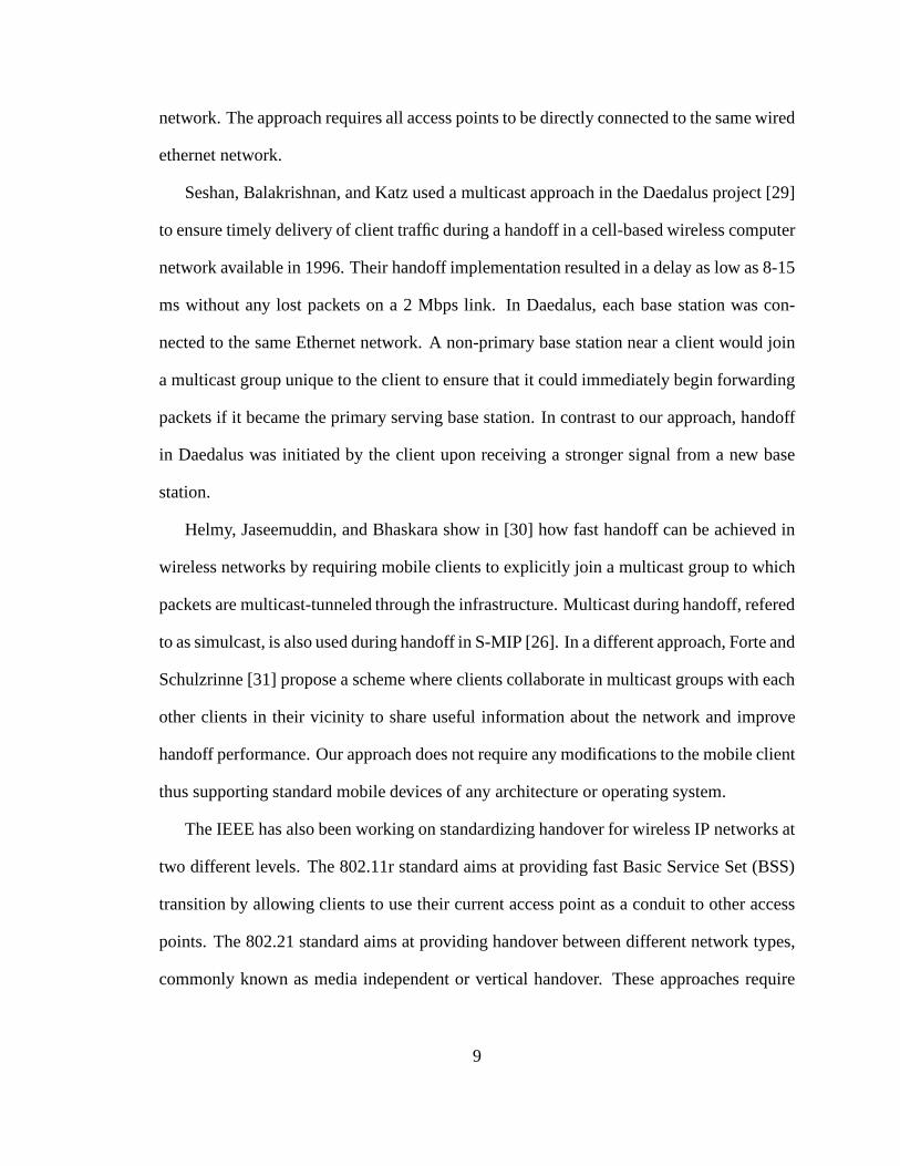
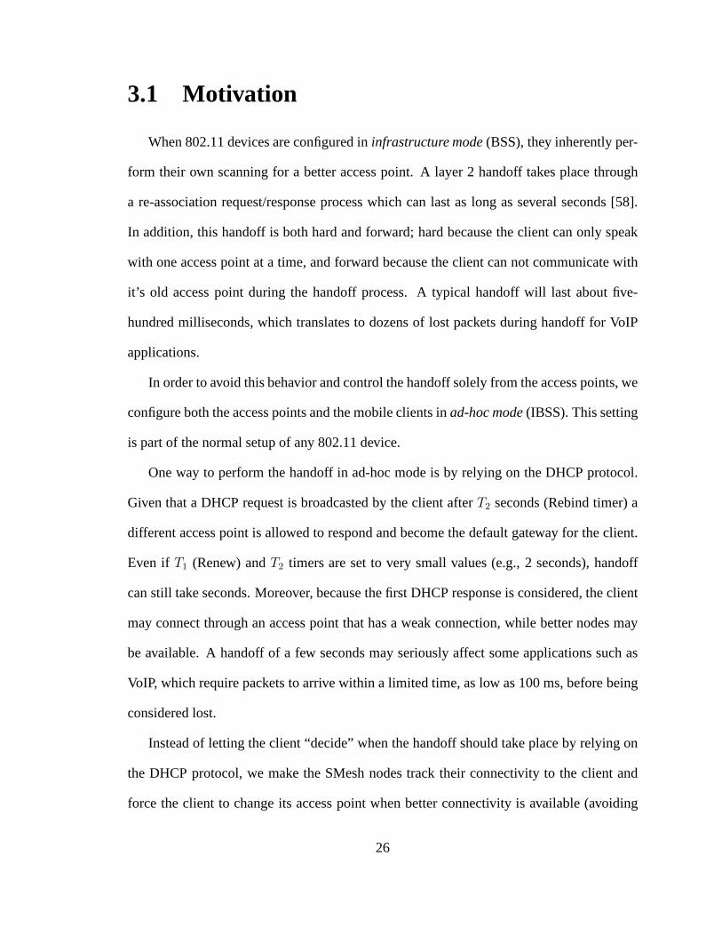
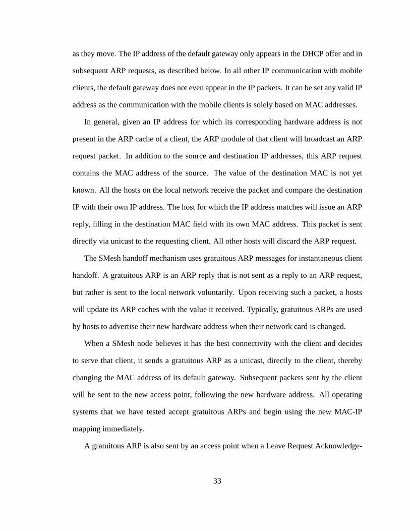
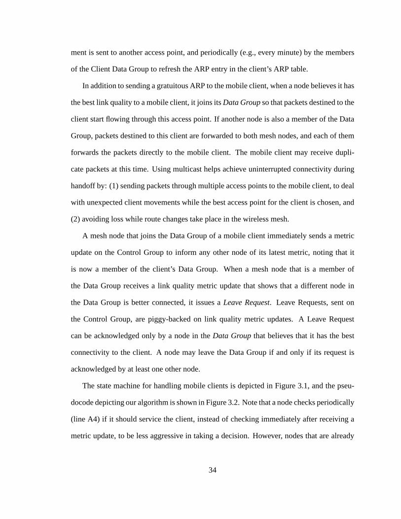
The state machine for handling mobile clients is depicted inFigure 3.1, and the pseu-
docode depicting our algorithm is shown in Figure 3.2. Note that a node checks periodically
(line A4) if it should service the client, instead of checking immediately after receiving a
metric update, to be less aggressive in taking a decision. However, nodes that are already
34
Handling Client
Monitoring Client
Requesting to Leave
Conditions Handle_Client: My_Metric > Highest_Metric(Data Group) * Threshold AND
My_Rank(Nodes in MonitoringClient state) <= Maximum_Concurrent_Joins (in our case 2) Handle_Client2: My_Rank(Nodes in HandlingClient or RequestingToLeave state) == 1 My_Rank(list): sort list in decreasing order of their metric value, then by IP address to break ties, and return index of local node
Receive Leave Request ACK AND Valid Leave Request ID Acknowledged
Idle
New Client Detected
Client out of reach Timeout
Client out of reach Timeout
Metric_Update AND NOT Handle_Client2
( Metric_Update AND NOT Handle_Client2 ) OR Leave Request Loss Timeout
Evaluate_Local_State AND Handle_Client
Evaluate_Local_State AND NOT Handle_Client
Metric_Update AND Handle_Client2
Metric_Update AND Handle_Client2
Figure 3.1: State Machine for handling mobile clients
servicing the client check their state immediately after receiving an updated metric (line
F2) to service the handoff as fast as possible. During disagreements, more than one node
may be a member of the Data Group for some time, until the disagreement is resolved.
When a node issues aLeave Request, it includes a unique id that increases each time
the mesh node enters the RequestingToLeave state (line B11). A node can acknowledge
a Leave Requestonly if it is currently the one handling the client (line D2).Note that a
node cannot leave unless it receives an acknowledgment withthe ID used in the lastLeave
Request(line E2).
35
// Abbreviations: DG = data group, CG = control group, LR = leave request
States = {Idle, MonitoringClient, HandlingClient, RequestingToLeave}LR ID = 0
A1. New Client Detected(client i):A2. Join(CGi)A3. statei = MonitoringClientA4. Periodically(Evaluate Local State(i))A5. Periodically(Monitor Client(i))A6. Periodically(Send Metric Update(CGi))
B1. Evaluate Local State(client i):B2. if (state == MonitoringClient)B3. My Rank = Compute My Rank(CGi Members in state == MonitoringClient)B4. if (My Metrici > (Highest Metric(DGi Members) * Threshold) and My Rank <= 2)B5. Join(DGi)B6. Send Gratuitous ARP(i)B7. statei = HandlingClientB8. else if (state == HandlingClient)B9. My Rank = Compute My Rank(DGi Members)B10. if (My Rank != 1)B11. LR IDi = LR ID++B12. Send(LRLR IDi
)B13. statei = RequestingToLeaveB14. else if (state == RequestingToLeave)B15. My Rank = Compute My Rank(DGi Members)B16. if (My Rank == 1)B17. statei = HandlingClientB18. if (current statei != previous statei)B19. Send Metric Update(CGi)
C1. Compute My Rank(list):C2. sorted list = new list sorted in decreasing order of metric value,
using node id to break tiesC3. return the rank/index where local node is located in sorted list
E1. Receive LR ACK(client i):E2. if (statei == RequestingToLeave and ID(LR ACK) == LR IDi)E3. Leave(DGi)E4. statei = MonitoringClient
F1. Metric Update(client i):F2. if (state == HandlingClient or state == RequestingToLeave)F3. Evaluate Local State(i)
G1. Client out of reach timeout(client i):G2. if (I am member(DGi))G3. Leave(DGi)G4. Leave(CGi)G5. statei = Idle
Figure 3.2: Pseudocode for deciding when to join and leave the Control and Data Groups.
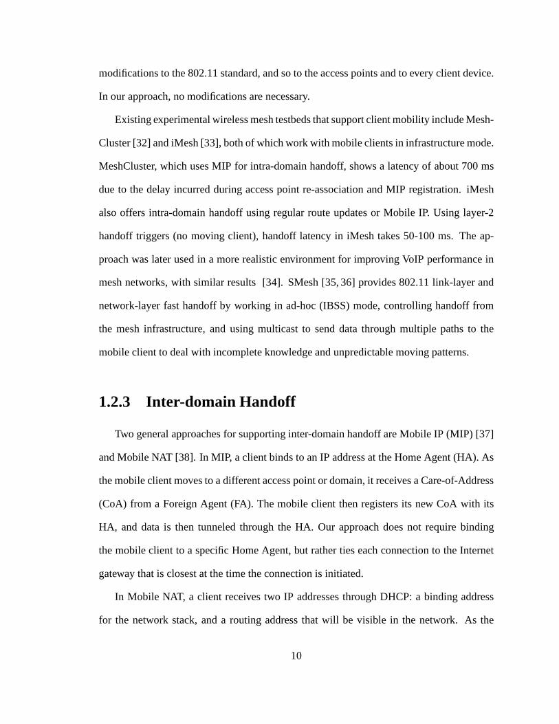
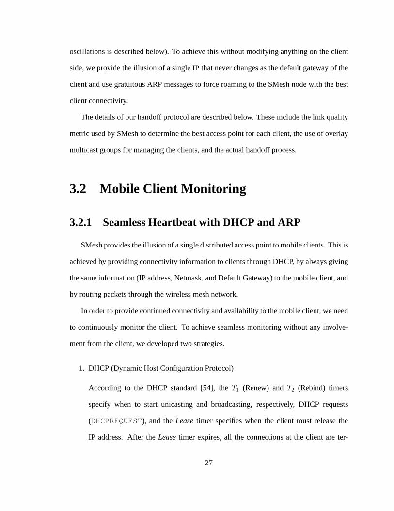
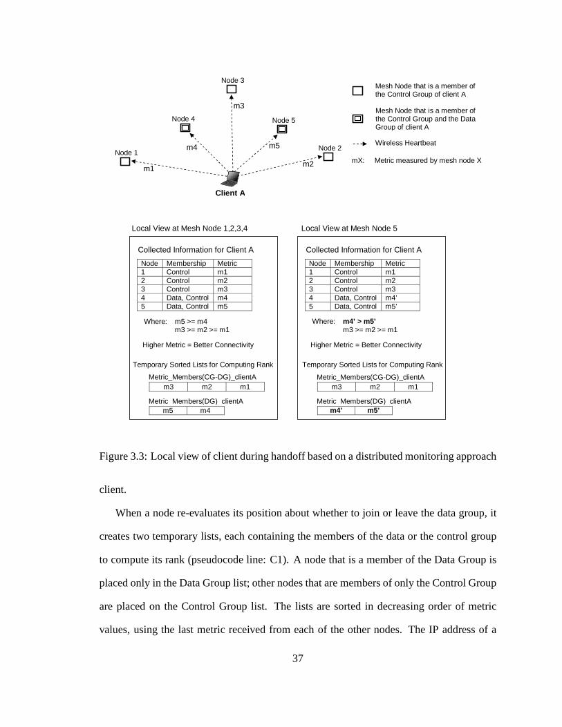
To understand how our algorithm works, let us consider Figure 3.3, where a Client is
within the vicinity of 5 mesh nodes. In this example, a handoff is taking from mesh node
4 to mesh node 5. All of the mesh nodes in the vicinity of the client are members of the
Control Group for that client, and two of them are also members of the Data Group for that
36
Client A
Metric_Members(CG-DG)_clientA
m5 m4
m3 m2 m1
m4
Mesh Node that is a member of the Control Group of client A
m5
m1 m2
m3
Wireless Heartbeat
Local View at Mesh Node 1,2,3,4
Metric_Members(DG)_clientA
mX: Metric measured by mesh node X
Mesh Node that is a member of the Control Group and the Data Group of client A
Collected Information for Client A
Node Membership Metric 1 Control m1 2 Control m2 3 Control m3 4 Data, Control m4 5 Data, Control m5
Temporary Sorted Lists for Computing Rank
Where: m5 >= m4 m3 >= m2 >= m1
Node 2
Node 5
Node 3
Node 4
Node 1
Higher Metric = Better Connectivity
Metric_Members(CG-DG)_clientA
m4’ m5’
m3 m2 m1
Metric_Members(DG)_clientA
Collected Information for Client A
Node Membership Metric 1 Control m1 2 Control m2 3 Control m3 4 Data, Control m4’ 5 Data, Control m5’ Where: m4’ > m5’ m3 >= m2 >= m1
Higher Metric = Better Connectivity
Local View at Mesh Node 5
Temporary Sorted Lists for Computing Rank
Figure 3.3: Local view of client during handoff based on a distributed monitoring approach
client.
When a node re-evaluates its position about whether to join or leave the data group, it
creates two temporary lists, each containing the members ofthe data or the control group
to compute its rank (pseudocode line: C1). A node that is a member of the Data Group is
placed only in the Data Group list; other nodes that are members of only the Control Group
are placed on the Control Group list. The lists are sorted in decreasing order of metric
values, using the last metric received from each of the othernodes. The IP address of a
37
node is used as a tie breaker. Therefore, the node with the highest metric will be placed
at the leftmost position of its list. The local view of a node and the temporary lists that
it creates are depicted in Figure 3.3. Each node, after computing its temporary lists, will
make a decision as follows:
Node 1:This node is a member of the Control Group only, and should consider joining
the Data Group if its metric is bigger (above some threshold)than the metric of the node in
the first position in the Data Group list.
Node 2: This node is a member of the Control Group only, and should also consider
joining the Data Group. The reason is that this node is not aware of the local view of Node
1 (i.e., Node 1 may think that Node 2 is in the first position). Anode in this position will
join the data group if its metric is bigger (above some threshold) than the metric of the
member in the first position of the Data Group.
Node 3: This node is a member of the Control Group only, and should notconsider
joining the data group. The reason is that we want to contain the number of nodes that can
suddenly join the data group for a node to limit the overhead associated with membership
changes and maintain some stability during handoff. No action is taken.
Node 4:This node is a member of the Data Group, and from its point of view, it is not
the number best node in his group. This node will send a Leave Request and continue to
service the client until it receives an acknowledgment to leave or it decides that it is the
best to handle the client.
Node 5:This node is a member of the Data Group, and from its point of view, it is not
the best node in the group. This node will send a Leave Requestand continue to service the
client until it receives an acknowledgment to leave or it decides that it is the best to handle
the client.
38
Since nodes 4 and 5 are in disagreement from their own perspective, they will both
service the client until one of them is able to take responsibility for handling the client.
That is, none of these nodes can send acknowledgments to a Leave Request.
This mechanism guarantees that at least one node is a member of the Data Group, unless
this node crashes. During disagreements, more than one nodemay be a member of the Data
Group for some time, until the disagreement is resolved. Ourexperiments show that this
usually lasts less than a quarter of a second during handoffs.
3.4 Experimental Results
3.4.1 Setup
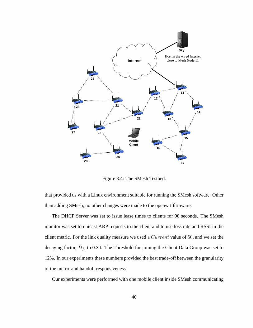
We deployed SMesh on 15 Linksys WRT54G wireless access points across several
floors in three buildings at The Johns Hopkins University. Only one of the routers was
connected to the Internet. Each of the mesh nodes is equippedwith one radio configured in
ad-hoc mode. The data rate on the mesh nodes was set to legacy 11 Mbps 802.11b unless
otherwise noted. The transmission power of the mesh nodes was set to 50 mW, and the
802.11 link-layer retransmission limit to 4. Unless specified, the topology of the mesh,
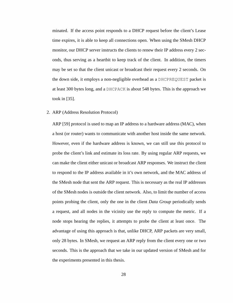
depicted in Figure 3.4, was stable.
We used two laptop computers, each with a Broadcom 802.11g Mini-PCI card in ad-
hoc mode as mobile clients. We used Linux for all experimentsthat required precise timing
measurements. Windows XP was used for a TCP throughput experiment, also showing
how SMesh operates across different platforms. No softwareother than the benchmarking
programs was installed on the laptop computers.
The Linksys routers were modified with the available custom openwrt firmware [61]
39
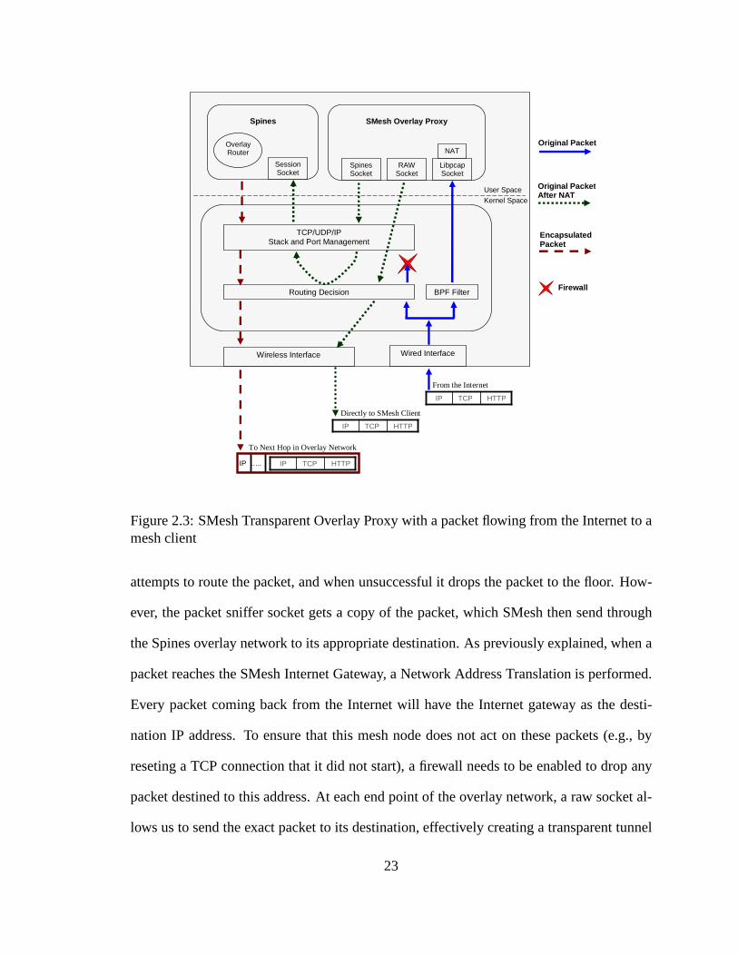
22
Sky
Mobile Client
Internet
21
25
24
27
12
13
11
14
15
16
17
28
23
26
Host in the wired Internet close to Mesh Node 11
Figure 3.4: The SMesh Testbed.
that provided us with a Linux environment suitable for running the SMesh software. Other
than adding SMesh, no other changes were made to the openwrt firmware.
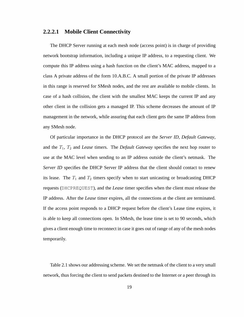
The DHCP Server was set to issue lease times to clients for 90 seconds. The SMesh
monitor was set to unicast ARP requests to the client and to use loss rate and RSSI in the
client metric. For the link quality measure we used aCurrent value of50, and we set the
decaying factor,Df , to 0.80. The Threshold for joining the Client Data Group was set to
12%. In our experiments these numbers provided the best trade-off between the granularity
of the metric and handoff responsiveness.
Our experiments were performed with one mobile client inside SMesh communicating
40
with a Linux machine that resided in the wired network (Internet), one wired hop away
from the mesh Internet gateway. The SMesh client will be referred to asClient and the
Linux box from the Internet asSky. In the experiments we sent full-duplex VoIP traffic,
one stream from Client to Sky and another from Sky to Client. The VoIP traffic consisted
of 160 byte UDP packets sent every20ms at a rate of64Kbps. This traffic is equivalent to
that of G.711, the standard encoder used for VoIP communication.
We first performed a stationary test to set the baseline of ourmoving experiments. We
then proceeded to move across two buildings starting and ending at the same location as
the stationary experiment. We then show how TCP behaves as wemove across the mesh.
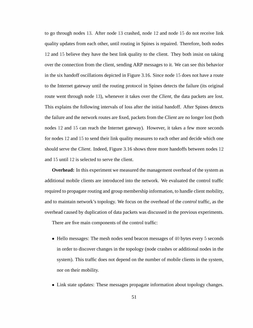
We tested the fail-over performance of our protocol when theaccess point of theClient
suddenly crashes (we disconnected the power of the Linksys router). Finally, we added
more mobile clients into the system, and determined how the management overhead of the
mesh network increases as the system needs to handle more clients.
For each test we monitored the one-way latency of each packet, the number of lost
packets, and the number of duplicate packets. The one-way latency was adjusted taking
into account the difference between the clocks at theClient andSkymachines. For VoIP
communication it was also important to track the delay jitter as well as how many packets
arrived within100ms, the rest being considered lost by the audio codec. Based on tcpdump
logs we reconstructed the handoff decisions and computed the communication overhead.
We show the handoff information in the graphs, noting also the number of wireless hops
from each mesh node to the Internet gateway. Note that the Client is connected to the access
point through a wireless link, and therefore its latency is influenced by this additional link.
When we state the number of hops of an access point we do not count the wireless hop
from the client to its current access point.
41
0
10
20
30
40
50
60
70
80
90
100
0 2000 4000 6000 8000 10000 12000 14000
121
131
Late
ncy
(ms)
Nod
e ID
hop
s
SEQ number
Lost: 1; Duplicate: 3;
packet latency (left axis) currently connected AP (right axis)
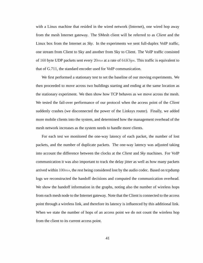
Figure 3.5: Stationary client. Mobile Clientis the receiver.
0
10
20
30
40
50
60
70
80
90
100
0 2000 4000 6000 8000 10000 12000 14000
121
131
Late
ncy
(ms)
Nod
e ID
hop
s
SEQ number
Lost: 1; Duplicate: 0;
packet latency (left axis) currently connected AP (right axis)
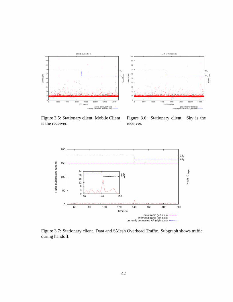
Figure 3.6: Stationary client. Sky is thereceiver.
0
50
100
150
200
60 80 100 120 140 160 180 200
121 131
Tra
ffic
(Kilo
bits
per
sec
ond)
Nod
e ID
hop
s
Time (s)
data traffic (left axis) overhead traffic (left axis)
currently connected AP (right axis)
0 4 8
12 16 20 24
130 140 150
121 131
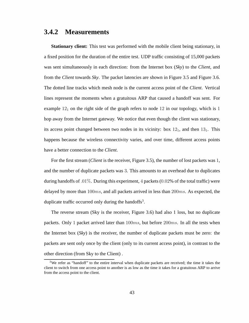
Figure 3.7: Stationary client. Data and SMesh Overhead Traffic. Subgraph shows trafficduring handoff.
42
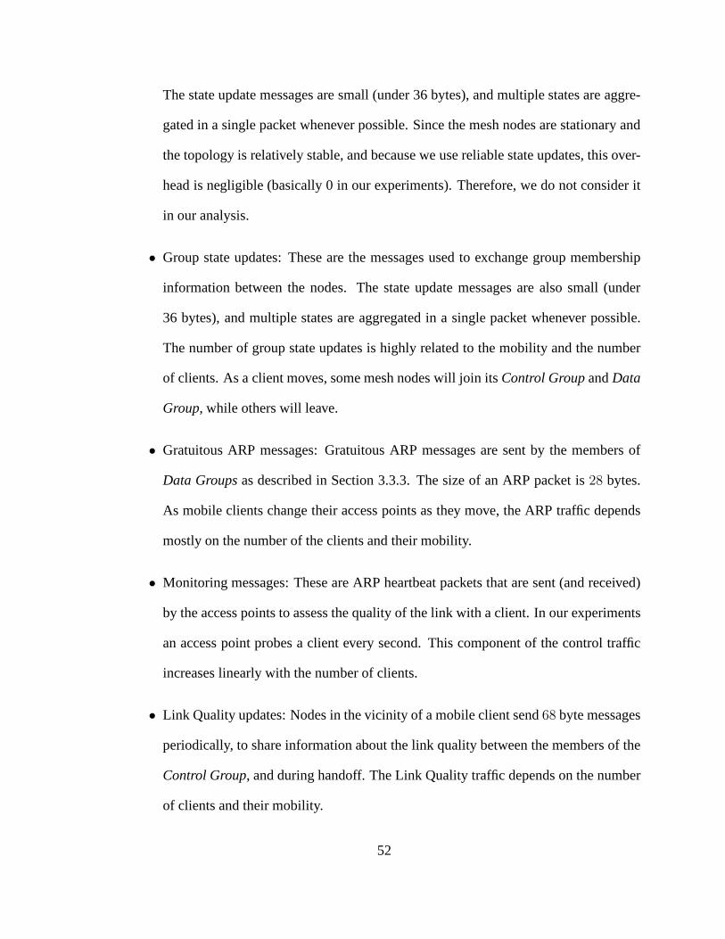
3.4.2 Measurements
Stationary client: This test was performed with the mobile client being stationary, in
a fixed position for the duration of the entire test. UDP traffic consisting of 15,000 packets
was sent simultaneously in each direction: from the Internet box (Sky) to theClient, and
from theClient towardsSky. The packet latencies are shown in Figure 3.5 and Figure 3.6.
The dotted line tracks which mesh node is the current access point of theClient. Vertical
lines represent the moments when a gratuitous ARP that caused a handoff was sent. For
example121 on the right side of the graph refers to node12 in our topology, which is1
hop away from the Internet gateway. We notice that even though the client was stationary,
its access point changed between two nodes in its vicinity: box 121, and then131. This
happens because the wireless connectivity varies, and overtime, different access points
have a better connection to theClient.
For the first stream (Client is the receiver, Figure 3.5), the number of lost packets was1,
and the number of duplicate packets was3. This amounts to an overhead due to duplicates
during handoffs of.01%. During this experiment,4 packets (0.02% of the total traffic) were
delayed by more than100ms, and all packets arrived in less than200ms. As expected, the
duplicate traffic occurred only during the handoffs3.
The reverse stream (Sky is the receiver, Figure 3.6) had also1 loss, but no duplicate
packets. Only1 packet arrived later than100ms, but before200ms. In all the tests when
the Internet box (Sky) is the receiver, the number of duplicate packets must be zero: the
packets are sent only once by the client (only to its current access point), in contrast to the
other direction (from Sky to the Client) .
3We refer as “handoff” to the entire interval when duplicate packets are received; the time it takes theclient to switch from one access point to another is as low as the time it takes for a gratuitous ARP to arrivefrom the access point to the client.
43
Figure 3.7 shows the overhead of our system in comparison with the data traffic. The
data traffic represents the data traffic sent and received by the client during the experiment.
The overhead traffic represents the data traffic sent, received, and forwarded by one of the
mesh nodes in the client vicinity (mesh node 13). The bandwidth measured is higher than
the full duplex 64Kbps UDP stream we sent, due to the IP and UDPheaders that accumulate
on the relatively small (160 byte) packets. (160 bytes per packet plus 8 bytes for the UDP
header plus 20 bytes for the IP header gives us 188 bytes -1504bits- per packet. With 50
packets per second each way, there are 9400 bytes -75200 bits- per second in each direction,
or 18800 bytes -150400 bits- per second total).
Control traffic from our system is represented as the bottom traffic line. It combines
the traffic from Spines (joins and leaves from multicast groups, hello keep-alive messages,
link state updates) and the traffic from client’s Control Group (link quality updates). Spines
sends keep-alive messages of 40 bytes every 4 seconds. Link state updates are sent only
when the mesh topology (formed by access points) changes. Join and leave messages
are sent only when a SMesh node (access point) joins or leavesa group. These types of
messages are aggregated such that a single Ethernet packet can contain up to 90 updates.
In order to keep track of the clients (posting link quality measures, sending ARP packets),
a SMesh node sends about 30 bytes per second (116 bytes in eachupdate, sent every few
seconds) for each client in its vicinity.
As we can see in Figure 3.7, a handoff takes place around second 140. The overhead
during handoff is shown in detail in the zoomed graph on the left of the figure. The increase
in control traffic show the moment when node 12 decided to jointhe Data Group, and sent
a join message to Spines (join and leave operations will generate a state update in the
Spines overlay network). As a consequence, there is a small spike in the data traffic since
44
data packets are duplicated. Right after, the old access point decided to leave the client
Data Group (it sends a Leave Request and it immediately receives the acknowledgment).
All of this happens in less than a second, so all of the overhead related to the handoff is
represented by the spike in the control traffic during handoff.
We use the above stationary client results as a baseline for the following tests, to provide
an idea of our wireless environment, and to overview the handoff process before a more
elaborate scenario.
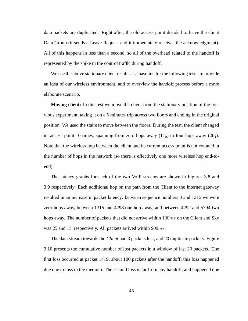
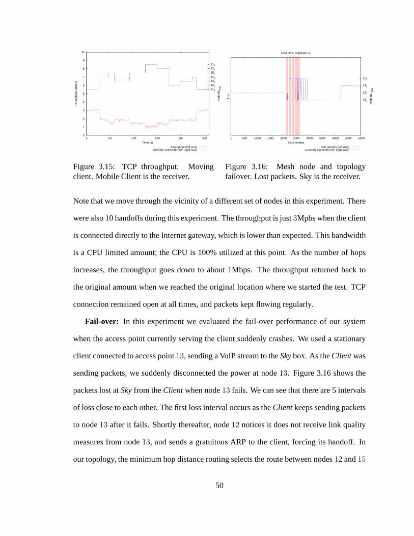
Moving client: In this test we move the client from the stationary position of the pre-
vious experiment, taking it on a5 minutes trip across two floors and ending in the original
position. We used the stairs to move between the floors. During the test, the client changed
its access point10 times, spanning from zero-hops away (110) to four-hops away (264).
Note that the wireless hop between the client and its currentaccess point is not counted in
the number of hops in the network (so there is effectively onemore wireless hop end-to-
end).
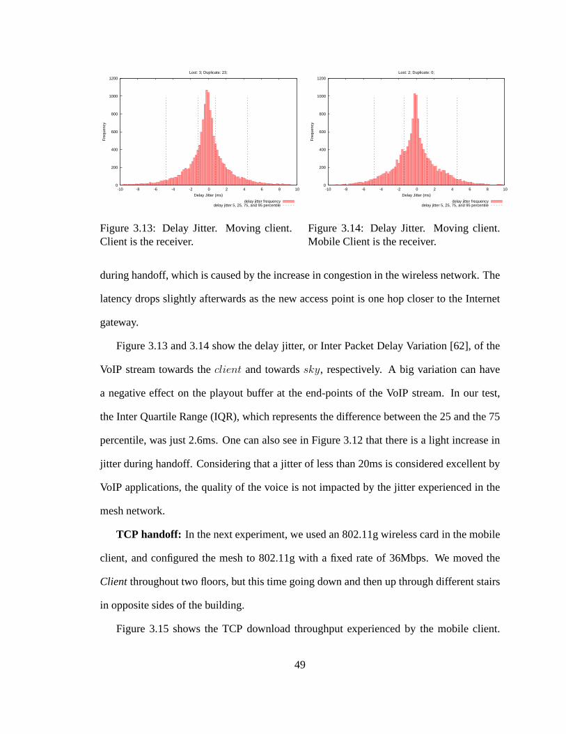
The latency graphs for each of the two VoIP streams are shown in Figures 3.8 and
3.9 respectively. Each additional hop on the path from the Client to the Internet gateway
resulted in an increase in packet latency: between sequencenumbers 0 and 1315 we were
zero hops away, between 1315 and 4298 one hop away, and between 4292 and 5794 two
hops away. The number of packets that did not arrive within100ms on the Client and Sky
was25 and13, respectively. All packets arrived within200ms.
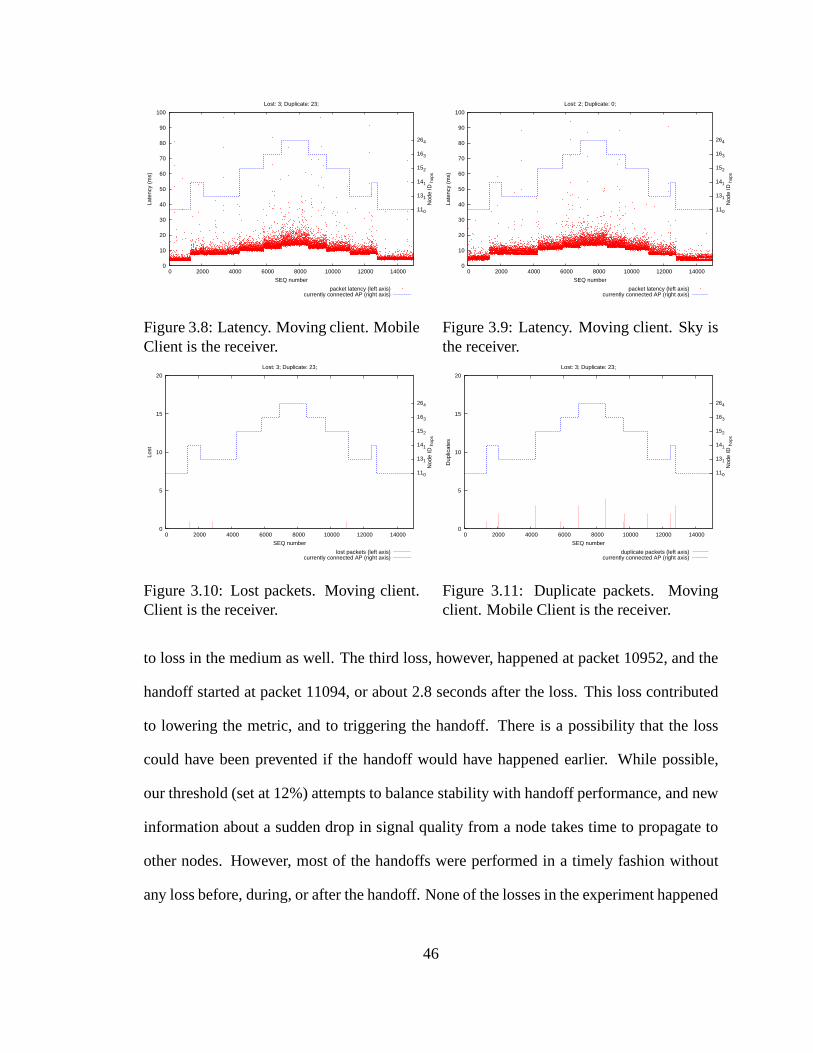
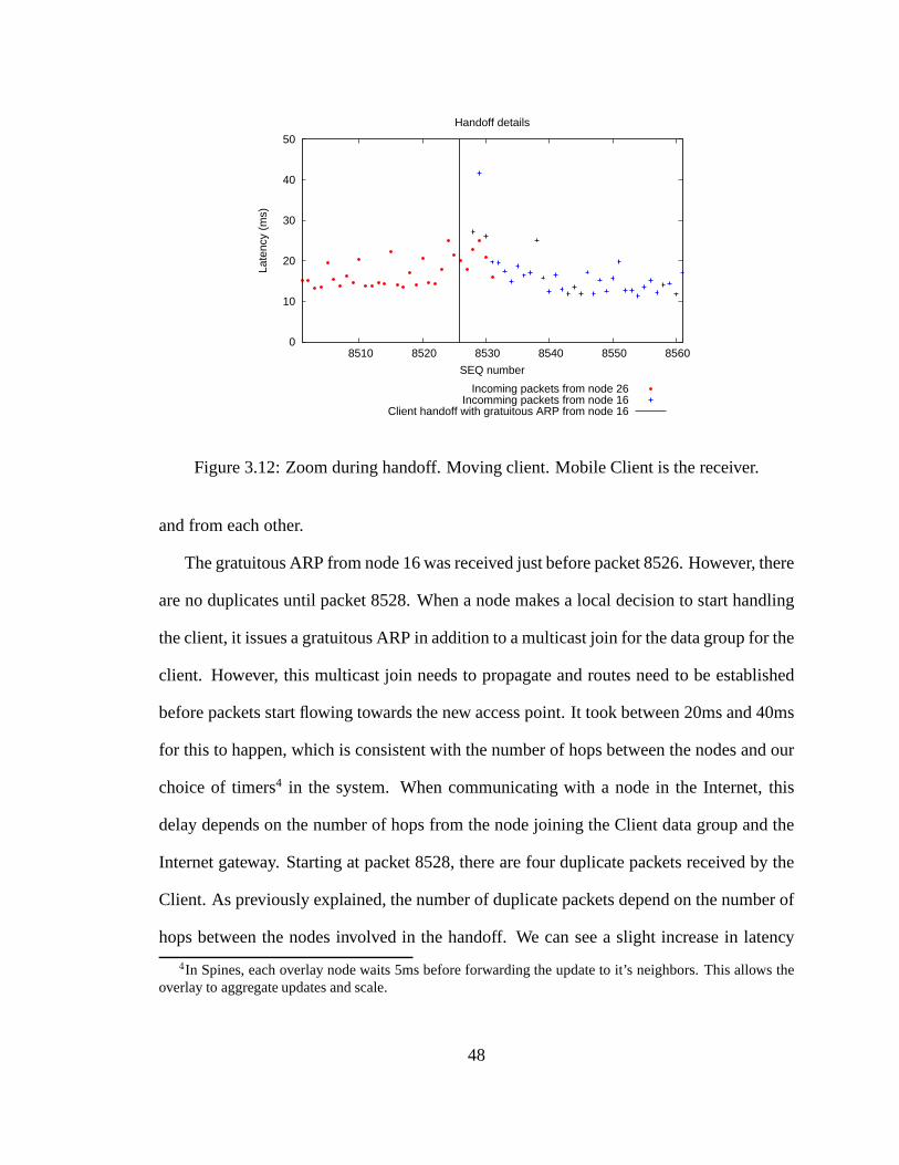
The data stream towards theClient had3 packets lost, and23 duplicate packets. Figure
3.10 presents the cumulative number of lost packets in a window of last 20 packets. The
first loss occurred at packet 1419, about 100 packets after the handoff; this loss happened
due due to loss in the medium. The second loss is far from any handoff, and happened due
45
0
10
20
30
40
50
60
70
80
90
100
0 2000 4000 6000 8000 10000 12000 14000
110
131
141
152
163
264
Late
ncy
(ms)
Nod
e ID
hop
s
SEQ number
Lost: 3; Duplicate: 23;
packet latency (left axis) currently connected AP (right axis)
Figure 3.8: Latency. Moving client. MobileClient is the receiver.
0
10
20
30
40
50
60
70
80
90
100
0 2000 4000 6000 8000 10000 12000 14000
110
131
141
152
163
264
Late
ncy
(ms)
Nod
e ID
hop
s
SEQ number
Lost: 2; Duplicate: 0;
packet latency (left axis) currently connected AP (right axis)
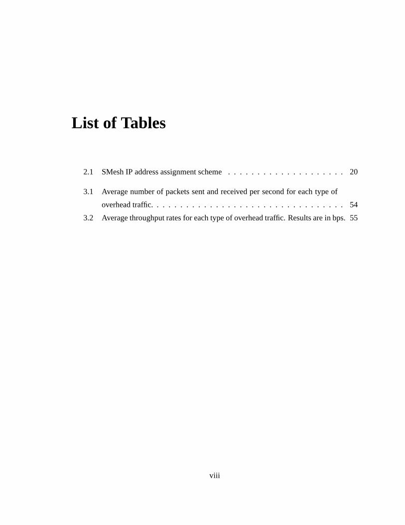
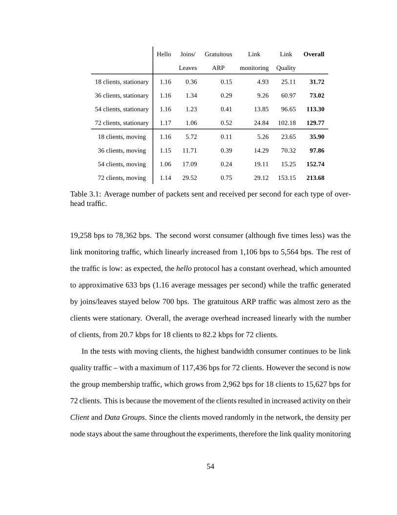
Table 3.2: Average throughput rates for each type of overhead traffic. Results are in bps.
traffic is about the same as in the stationary test. The gratuitous ARP traffic is higher than
before (each client experienced a handoff approximately every minute, which corresponds
to more than one handoff per second in the entire network) butoverall is extremely low. The
network topology remained unchanged causing the same amount of hello traffic. Overall,
the average overhead increased linearly with the number of clients, from 22.5 kbps for 18
clients to 127.1 kbps for 72 clients.
The aggregate management overhead increases linearly withthe addition of clients,
from 1.4 kbps per client for stationary clients, to 1.9 kbps per client for moving clients.
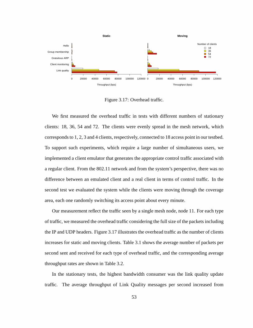
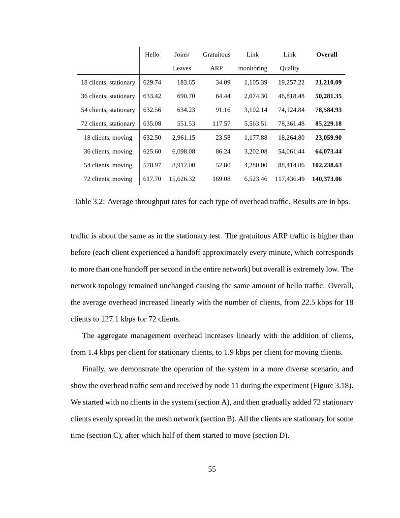
Finally, we demonstrate the operation of the system in a morediverse scenario, and
show the overhead traffic sent and received by node 11 during the experiment (Figure 3.18).
We started with no clients in the system (section A), and thengradually added 72 stationary
clients evenly spread in the mesh network (section B). All the clients are stationary for some
time (section C), after which half of them started to move (section D).
55
0
20000
40000
60000
80000
100000
120000
140000
160000
50 100 150 200 250 300 350 400 450
Thr
ough
put (
bps)
Time (s)
Tick = 5000 ms
A
B C
D
HelloGroup membership
Gratuitous ARPClient monitoring
Link quality
Figure 3.18: 18 nodes, 72 clients. Overhead Traffic. (A) no clients, (B) 72 clients connect,(C) all clients are stationary, (D) 36 of the clients start moving throughout the mesh.
Throughout the experiment, the hello and gratuitous ARP traffic stays very low, com-
pared to other components. As clients join the network, we see a small increase in the client
monitoring traffic, which remains stable after all the clients are connected. In contrast, as
clients join the network, we see a significant increase in group state update traffic due to
mesh nodes joining theControl andData groups for the clients in their vicinity. Because
the clients are stationary, this traffic goes back to zero after the updates are propagated in
the network (section C). However, when some of the clients start to move (section D), the
group state overhead traffic increases again as an effect of membership changes in theCon-
trol group (due to new clients coming within the vicinity of mesh node 11) and theData
group (due to handoffs). In the same way, link quality trafficincreases while the clients
join the network, but afterwards remains high since mesh nodes periodically share link
quality information. We notice a small increase in this traffic when clients start to move
(section D), mainly due to more clients coming within the vicinity of node 11.
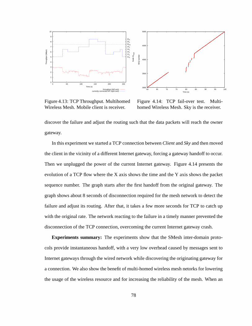
Experiments summary: The experiments show that the SMesh protocols provide in-
stantaneous handoff, with a low overhead caused by duplicates during periods of instability
caused by handoffs. When sending and receiving both UDP and TCP traffic, the connec-
tions were not interrupted, and the loss when a mobile clientroams was minimal.
56
As expected, a short disconnection happens when the access point serving the client
suddenly crashes. In such a case, the system re-adjusts, andwithin a few seconds is able to
re-route packets through the network.
The management overhead of the mesh network grows linearly with the number of
clients, in the worst case at a rate of about 2 kbps per client.This overhead does not
depend on the amount of data the mobile clients send or receive. Considering that the
capacity of 802.11g wireless networks is in the order of tensof Mbps, we conclude that the
management overhead of SMesh is reasonable.
57
Chapter 4
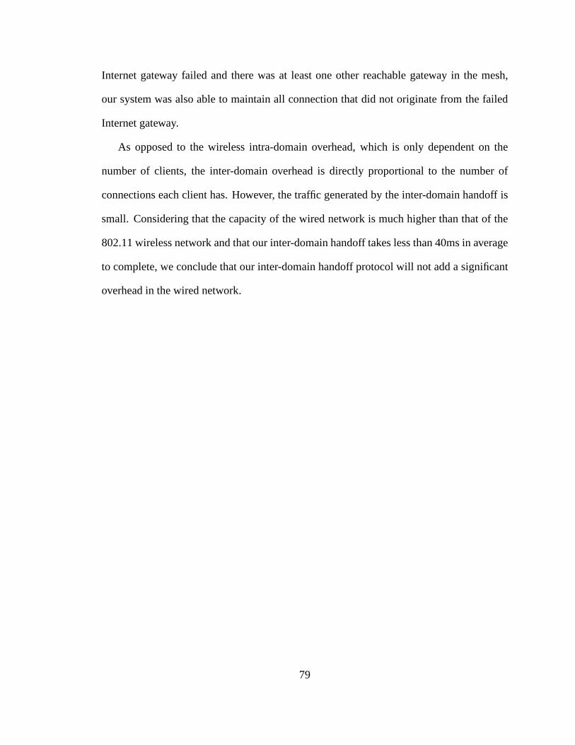
Achieving Fast Inter-domain Handoff
This chapter present the protocols that we developed to support hybrid routing and
fast inter-domain handoff in multi-homed wireless mesh networks. The protocol integrates
wired and wireless communication and optimizes performance of the hybrid routing, in our
case by minimizing the usage of wireless transmissions.
We start by overviewing multi-homed wireless mesh networks, and describe our hybrid
overlay architecture, including topology formation and hybrid routing metric. We then
describe our inter-domain handoff protocol, and how TCP andUDP connections need to
be treated differently to maintain connectivity. Finally,we demonstrate that inter-domain
handoffs occur instantaneously, with virtually no loss or delay, for both TCP and UDP
connections.
4.1 Multi-homed Wireless Mesh Networks
A wireless mesh network extends the connectivity range of mobile devices by using
multiple access points to create a mesh topology and forwardpackets over multiple wireless
58
hops. As the size of a wireless mesh network increases, the number of Internet connected
access points (Internet gateways) needs to increase to disperse traffic and avoid congestion.
In practice, Internet gateways will reside at different locations and will often be connected
to different network domains. We refer to such mesh networksasmulti-homed. In this type
of networks, a mobile client is served by a nearby access point that forwards data packets
(potentially over multiple wireless hops) to its closest Internet gateway.
Multi-homing poses a challenge in providing continuous connectivity to mobile clients
that may move between the areas covered by different access points. Those access points
will often have different Internet gateways closest to them. When such a transition (hand-
off) occurs, we would like to maintain all previously opened connections, and transfer
them to the new Internet gateway as quickly as possible, without any involvement from the
mobile device.
In our approach, new connections always use the closest Internet gateway at the time of
their creation, while existing connections are forwarded through the wired infrastructure to
the Internet gateway where they were originally initiated.As the handoff process requires
routing agreement and transferring connections between the involved Internet gateways,
our protocol guarantees that packets are routed correctly,at all times.
4.2 A Hybrid Overlay Architecture
A wireless mesh network is comprised of multiple access points, possibly distributed
in several islands of wireless connectivity such as different buildings located close to each
other or parts of the same building. Access points inside a wireless island can communicate,
potentially using multiple intermediate hops. One or more access points in each wireless
59
Access Point
Internet Connected
Access Point
Wireless Connection
Wired Connection
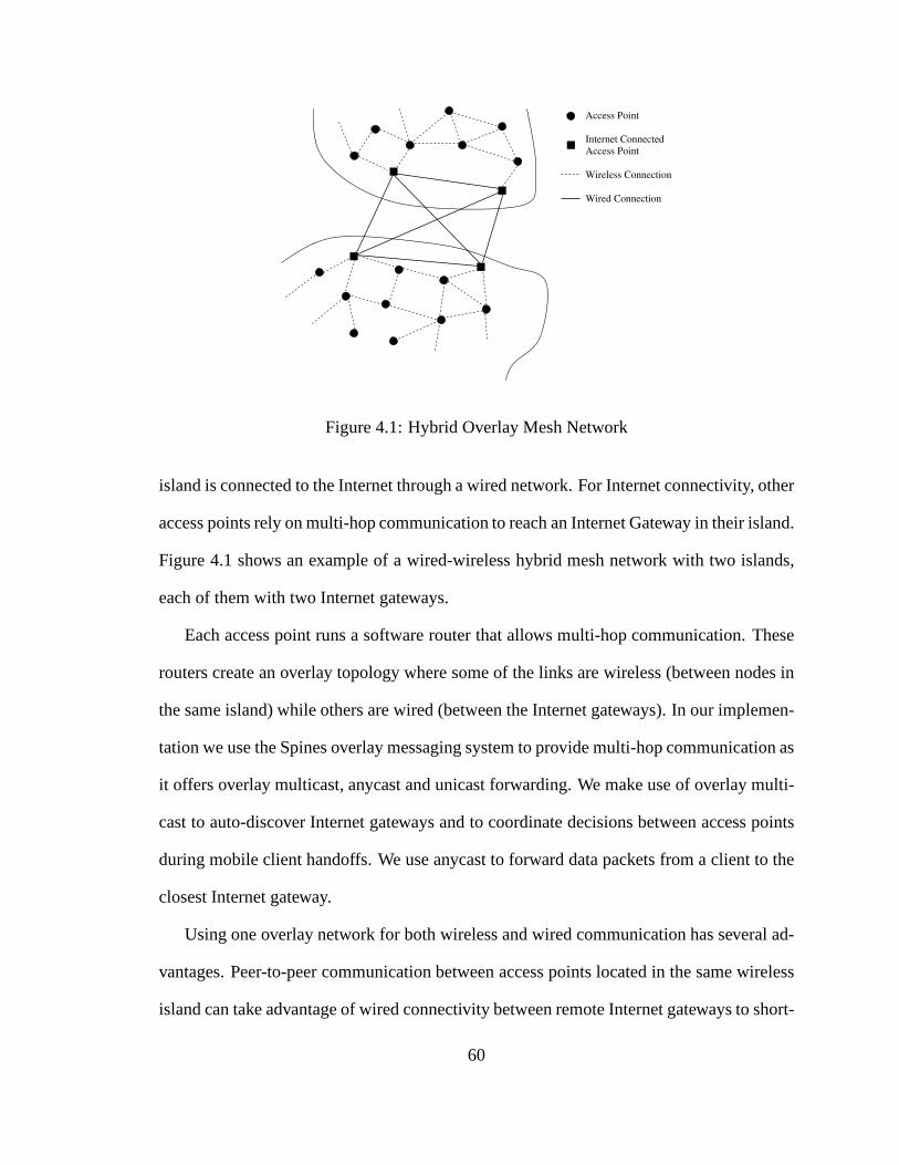
Figure 4.1: Hybrid Overlay Mesh Network
island is connected to the Internet through a wired network.For Internet connectivity, other
access points rely on multi-hop communication to reach an Internet Gateway in their island.
Figure 4.1 shows an example of a wired-wireless hybrid mesh network with two islands,
each of them with two Internet gateways.
Each access point runs a software router that allows multi-hop communication. These
routers create an overlay topology where some of the links are wireless (between nodes in
the same island) while others are wired (between the Internet gateways). In our implemen-
tation we use the Spines overlay messaging system to providemulti-hop communication as
it offers overlay multicast, anycast and unicast forwarding. We make use of overlay multi-
cast to auto-discover Internet gateways and to coordinate decisions between access points
during mobile client handoffs. We use anycast to forward data packets from a client to the
closest Internet gateway.
Using one overlay network for both wireless and wired communication has several ad-
vantages. Peer-to-peer communication between access points located in the same wireless
island can take advantage of wired connectivity between remote Internet gateways to short-
60
cut multiple wireless hops. In addition, the diameter of thenetwork is decreased, improving
route update latency and overhead related to control messages on the overlay network.
4.2.1 Topology Formation
The topology formation starts with each access point broadcasting its presence periodi-
cally. Neighboring nodes create bidirectional links and advertise their connectivity through
a link state protocol to other nodes in the network. The link state protocol uses link-based
acknowledgments such that after a link was advertised to other access points in the network,
it will not be advertised again, unless it changes its status. This reduces communication
overhead for managing the topology.
Internet gateways join a multicast group calledInternet Gateway Multicast Group
(IGMG) on which they periodically advertise their wired interface IP address. The multi-
cast routing is handled by the underlying overlay infrastructure, as explained in the previous
chapter. When two Internet gateways receive each other’s advertisements (which initially
travels through the wireless infrastructure to the membersof the multicast group), they con-
nect through a wired overlay link. This way, the Internet gateways inside an island form a
fully connected graph using their wired infrastructure, while the other access points inside
the island interconnect based on the wireless connectivity. In order to interconnect wireless
islands, at least one Internet gateway in each island needs to be pre-configured to connect
to a set of Internet gateways such that an initial connected graph is formed. Then, multi-
cast advertisements from all gateways will be propagated, Internet gateways will connect
to each other, and eventually, a fully connected logical graph between all Internet gateways
in all islands is formed.
61
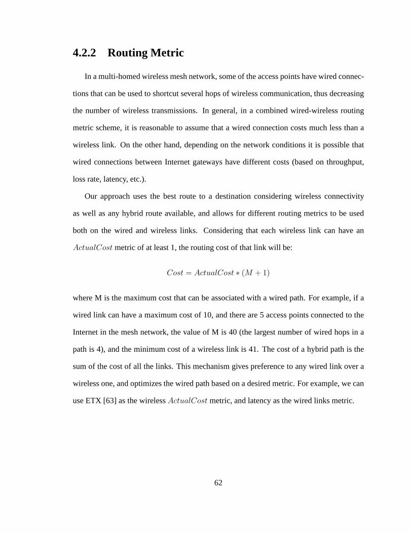
4.2.2 Routing Metric
In a multi-homed wireless mesh network, some of the access points have wired connec-
tions that can be used to shortcut several hops of wireless communication, thus decreasing
the number of wireless transmissions. In general, in a combined wired-wireless routing
metric scheme, it is reasonable to assume that a wired connection costs much less than a
wireless link. On the other hand, depending on the network conditions it is possible that
wired connections between Internet gateways have different costs (based on throughput,
loss rate, latency, etc.).
Our approach uses the best route to a destination considering wireless connectivity
as well as any hybrid route available, and allows for different routing metrics to be used
both on the wired and wireless links. Considering that each wireless link can have an
ActualCost metric of at least 1, the routing cost of that link will be:
Cost = ActualCost ∗ (M + 1)
where M is the maximum cost that can be associated with a wiredpath. For example, if a
wired link can have a maximum cost of 10, and there are 5 accesspoints connected to the
Internet in the mesh network, the value of M is 40 (the largestnumber of wired hops in a
path is 4), and the minimum cost of a wireless link is 41. The cost of a hybrid path is the
sum of the cost of all the links. This mechanism gives preference to any wired link over a
wireless one, and optimizes the wired path based on a desiredmetric. For example, we can
use ETX [63] as the wirelessActualCost metric, and latency as the wired links metric.
62
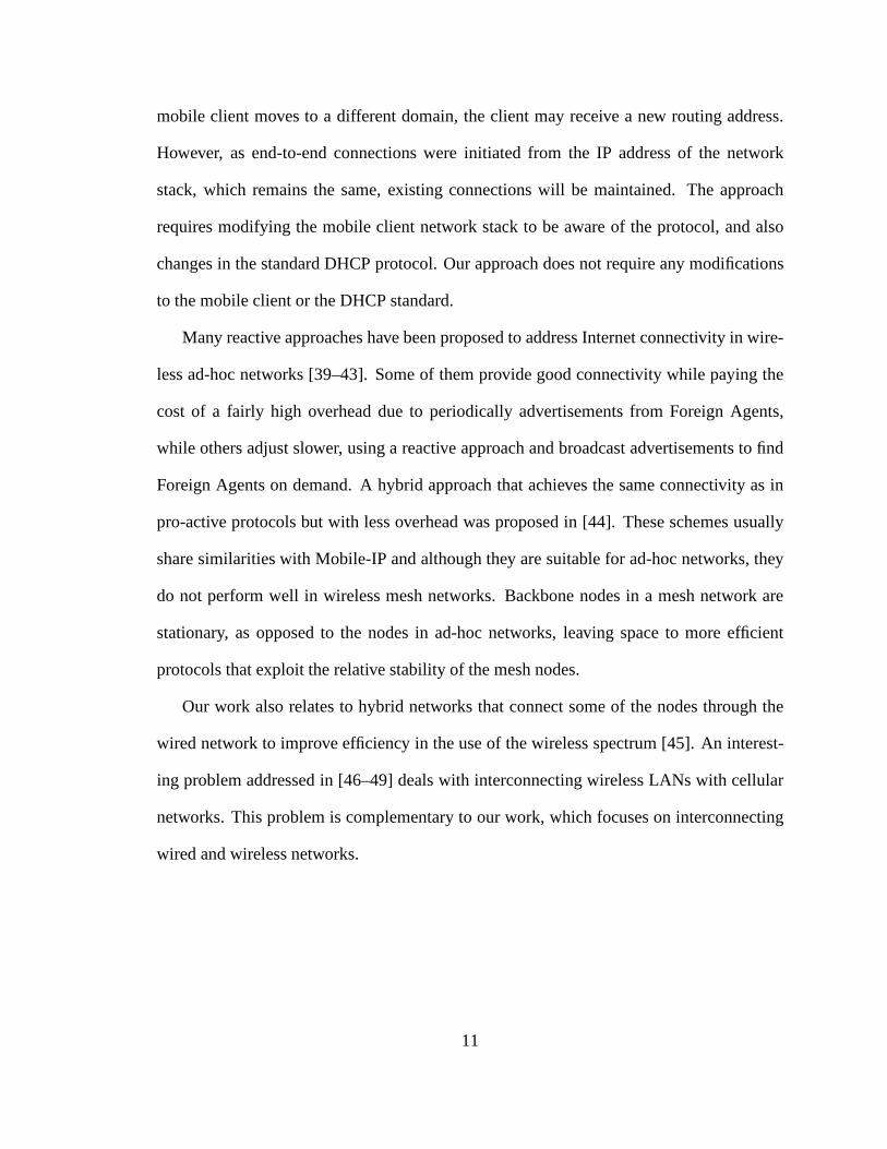
Send Owner Notification on IGMG
Packet received
Send packetto Owner
OWNER = Me
Send packet toIGMG
Send packet toDestination
Owner
Known?
SYN?
Am I the
Owner
Discard
TCP/UDP?
Timeout?
Received
FromReceived
From
Discard
Send packet toIGMG and Destination
Received
From
Discard
Yes No
UDP
Client
No
IGMG
IGMG
Yes
Yes
TCP
Client
No
IGMG
Yes
No
IGMG
ClientDone
Client Received
From
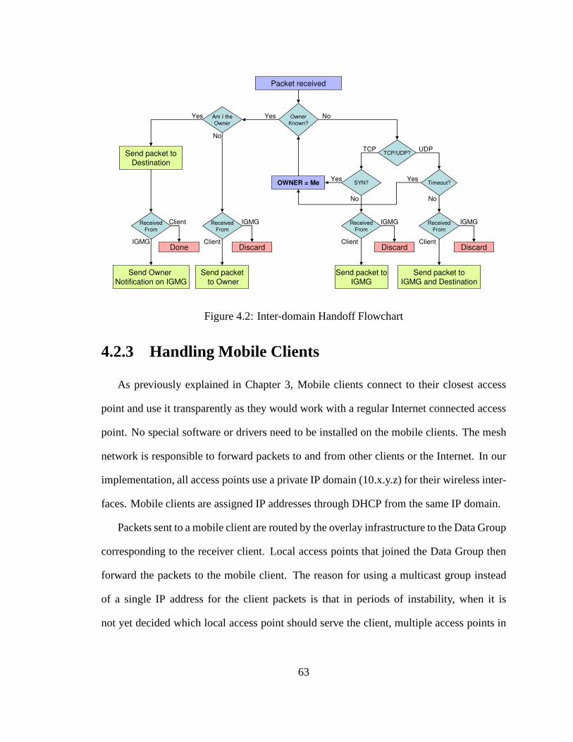
Figure 4.2: Inter-domain Handoff Flowchart
4.2.3 Handling Mobile Clients
As previously explained in Chapter 3, Mobile clients connect to their closest access
point and use it transparently as they would work with a regular Internet connected access
point. No special software or drivers need to be installed onthe mobile clients. The mesh
network is responsible to forward packets to and from other clients or the Internet. In our
implementation, all access points use a private IP domain (10.x.y.z) for their wireless inter-
faces. Mobile clients are assigned IP addresses through DHCP from the same IP domain.
Packets sent to a mobile client are routed by the overlay infrastructure to the Data Group
corresponding to the receiver client. Local access points that joined the Data Group then
forward the packets to the mobile client. The reason for using a multicast group instead
of a single IP address for the client packets is that in periods of instability, when it is
not yet decided which local access point should serve the client, multiple access points in
63
the vicinity of the mobile client may forward the data packets (also allowing us to deal
with unpredictable moving patterns). When an access point receives a packet that has a
destination outside the wireless mesh network, it simply forwards it to the Internet Gateway
Anycast Group, an overlay anycast group to which all Internet gateways join. This way,
packets are always sent to the closest Internet gateway.
4.3 Inter-domain Handoff Management
4.3.1 Internet Gateway Control Group
Packets exchanged between two mobile clients, either in thesame or in different wire-
less islands, simply use shortest path multicast trees reaching the access points that decided
to serve each client. Note that in the stable case, when mobile client communication does
not require a handoff, only one access point in the vicinity of a client will join its multi-
cast Data Group. Therefore, most of the time, the multicast trees are simply linear paths.
The multicast trees adjust automatically when mobile clients roam within the vicinity of
different access points, as the access points join or leave the client’s multicast Data Group.
In peer-to-peer communication, packets will follow the shortest paths with no need for a
special handoff at the Internet gateways.
In contrast, communication between mobile clients and the Internet is relayed through
the closest Internet gateway. As mobile clients move withinthe wireless mesh network,
they may get closer, network-wise, to a different Internet gateway in the same island, or
they may move to a different wireless island. In this case, the anycast packets, which are
forwarded to the closest Internet gateway, will no longer reach the original gateway, and
therefore a solution is required to maintain existing connections.
Mobile clients in SMesh work on a private network, and a Network Address Transla-
tion (NAT) is required at the Internet gateway when communicating with an external host.
Each Internet gateway has a different external IP address. Applications using TCP, and in
some cases, applications running on top of UDP require packets to be forwarded through
the initial forwarding Internet gateway through the entirelife of the connection. Changing
one end-point of the connection (the IP address of the Internet gateway) is often impos-
sible without breaking the existing connection, and therefore it is better for the handoff
mechanisms to mask this problem inside the mesh network.
One potential solution is to exchange complete connection information (NAT tables)
between the Internet gateways periodically and forward packets to the original owner of
the connection using the wired connectivity. Such a solution can only be as fast as the
time between two periodic NAT table exchanges, and cannot support real-time traffic such
as VoIP. To support real-time traffic, one can advertise connection information to all the
Internet gateways when the NAT entries are created. However, this technique tends to
be wasteful, as not all mobile clients may move and change their Internet gateway. The
problem is most notable when clients are browsing the Internet, as many connections are
established for each website and, all of these information,which is relevant only for a small
amount of time, would be sent to all of the Internet gateways.
65
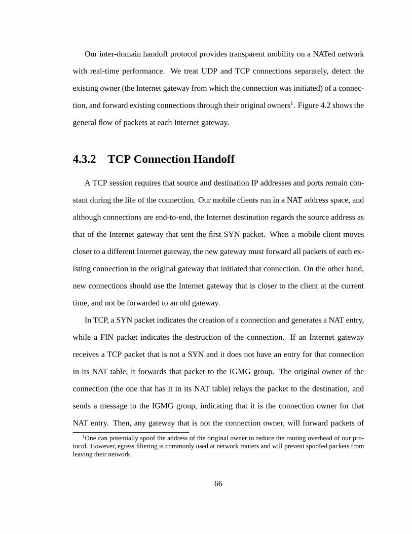
Our inter-domain handoff protocol provides transparent mobility on a NATed network
with real-time performance. We treat UDP and TCP connections separately, detect the
existing owner (the Internet gateway from which the connection was initiated) of a connec-
tion, and forward existing connections through their original owners1. Figure 4.2 shows the
general flow of packets at each Internet gateway.
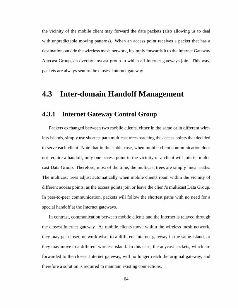
4.3.2 TCP Connection Handoff
A TCP session requires that source and destination IP addresses and ports remain con-
stant during the life of the connection. Our mobile clients run in a NAT address space, and
although connections are end-to-end, the Internet destination regards the source address as
that of the Internet gateway that sent the first SYN packet. When a mobile client moves
closer to a different Internet gateway, the new gateway mustforward all packets of each ex-
isting connection to the original gateway that initiated that connection. On the other hand,
new connections should use the Internet gateway that is closer to the client at the current
time, and not be forwarded to an old gateway.
In TCP, a SYN packet indicates the creation of a connection and generates a NAT entry,
while a FIN packet indicates the destruction of the connection. If an Internet gateway
receives a TCP packet that is not a SYN and it does not have an entry for that connection
in its NAT table, it forwards that packet to the IGMG group. The original owner of the
connection (the one that has it in its NAT table) relays the packet to the destination, and
sends a message to the IGMG group, indicating that it is the connection owner for that
NAT entry. Then, any gateway that is not the connection owner, will forward packets of
1One can potentially spoof the address of the original owner to reduce the routing overhead of our pro-tocol. However, egress filtering is commonly used at networkrouters and will prevent spoofed packets fromleaving their network.
66
that connection to the respective owner, finalizing the connection handoff process. Figure
4.3 shows the stages of such a TCP connection handoff.
If packets arrive at an Internet gateway at a fast rate, several packets may be sent to the
IGMG group before the connection owner can respond. If no Internet gateway claims the
connection within a certain timeout (in our implementation3 seconds), the new gateway
claims the connection, forwarding the packets directly to the Internet destination. This will
break the TCP connection, which is the desired behavior in such a case, since it is likely
that the original owner crashed or got disconnected. Causing the Internet host to close the
connection avoids connection hanging for a long period of time (TCP default is2 hours).
4.3.3 UDP Connection Handoff
Most real-time applications use the best effort UDP serviceand build their own protocol
on top of UDP to meet specific packet latency requirements. Some applications, such as
DNS, do not establish connections between participants. Others, such as SIP in VoIP,
establish specific connections defined by a pair of an IP address and a port at both ends of
the connection.
When an Internet gateway receives a UDP packet with a new pairof source and destina-
tion addresses or ports, it cannot distinguish between the case where this is the first packet
of a new connection, and the case where the packet belongs to an existing connection es-
tablished through a different Internet gateway.
We classify UDP traffic on a port number basis asconnection-lessand connection-
oriented, and choose connection-oriented as the default protocol. Connection-less UDP
traffic is forwarded directly after receiving it from the mesh network, on the current shortest
path. DNS and NTP traffic falls into this category.
67
Upon receiving a new connection-oriented UDP packet that has an Internet destination,
an Internet gateway relays that packet to its destination, and also forwards it to the multi-
cast group that all Internet gateways join (as opposed to theTCP case, where the access
point only sends packets to the multicast group). If the UDP packet belongs to a connec-
tion that was already established, the Internet gateway that is the original owner of the
connection also relays the packet to the destination, and sends a response to the Internet
gateway multicast group. After receiving the response, theinitial gateway will forward
subsequent packets directly to the original gateway, and will no longer relay UDP pack-
ets of that connection (with the same source and destinationaddresses and ports) to the
Internet. If a response does not arrive within a certain timeout (in our implementation
500 milliseconds), the Internet gateway will claim ownership of the UDP connection, will
stop forwarding packets of that connection to the IGMG group, and will continue to relay
packets to the Internet.
4.3.4 Overhead
Internet gateways generate some overhead traffic on the wired network during the inter-
domain handoff. Data packets are multicasted over the wirednetwork to all other Internet
gateways until the owner of the connection responds. In our tests, this process took between
10 ms and 60 ms. Note that data packets are forwarded in parallel to the end-host and their
latency is much less. After the first handoff of a connection takes place, all Internet gate-
ways are informed about the owner of that connection, and therefore new data packets are
sent directly to the connection owner. As opposed to the wireless intra-domain overhead,
which is only dependent on the number of clients, the inter-domain overhead is directly
proportional to the number of connections each client has. However, the traffic generated
68
by the inter-domain handoff is small, and uses only the wirednetwork.
4.3.5 Discussion
Due to handoff and/or metric fluctuations, there is a possibility that packets coming
from a mobile client and belonging to the same flow alternate between two Internet gate-
ways. This may lead to more than one gateways claiming the ownership of the connection.
We encounter such case in TCP when a client retransmits a SYN connection request, and
this request is routed through a different Internet gateway. In UDP, such case may occur
when two different Internet gateways start forwarding client packets for the same connec-
tion at about the same time. A plausible solution for TCP is todelay ownership decision
until a full three-way TCP handshake is seen by the Internet gateway. For UDP, when there
is more than one ownership request in parallel, the gatewaysdecide the rightful owner of
the connection based on feedback traffic from the end-host orlowest IP address.
Also note that, in general, our inter-domain handoff protocol can be applied in less so-
phisticated architectures. For example, all Internet gateways can be pre-configured with the
complete set of Internet gateways that will participate in the inter-domain handoff. How-
ever, route optimizations provided by the overlay network,both in the wired and wireless
network, will not be available, and some other mechanism must be devised to ensure fast
seamless handoff for mobile clients at the intra-domain level.
69
22
Sky
Mobile Client
31
Internet
32
33
21
25
24
27
12
13
11
14
15
16
17
28
23
26
Host in the wired Internet close to Mesh Node 11
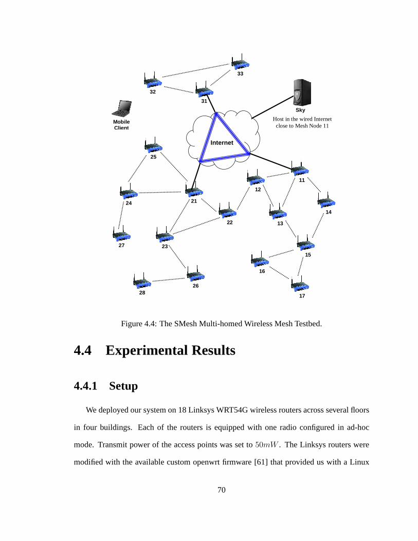
Figure 4.4: The SMesh Multi-homed Wireless Mesh Testbed.
4.4 Experimental Results
4.4.1 Setup
We deployed our system on 18 Linksys WRT54G wireless routersacross several floors
in four buildings. Each of the routers is equipped with one radio configured in ad-hoc
mode. Transmit power of the access points was set to50mW . The Linksys routers were
modified with the available custom openwrt firmware [61] thatprovided us with a Linux
70
environment suitable for running the SMesh software. Otherthan adding SMesh, no other
changes were made to the openwrt firmware.
We used two laptop computers, each with a Broadcom 802.11g Mini-PCI card in ad-
hoc mode as mobile clients. We used Linux for all experimentsthat required precise timing
measurements. Windows XP was used for a TCP throughput experiment, also showing
how SMesh operates across different platforms. No softwareother than the benchmarking
programs was installed on the laptop computers.
The topology of the wireless testbed used in our experimentsis shown in Figure 4.4.
The topology consists of one main island with two Internet gateways, and another smaller
island with one Internet gateway. The islands are disconnected due to a large open grass
area between the buildings. However, a mobile client located between the two islands can
reach both networks. Each of the Internet gateways is part ofa different domain on the cam-
pus network and within 6 hops of each other through the wired network. Unless otherwise
specified, the topology between the access points was staticduring the experiments. Each
access point box has an identifier, refered to as node id. The node-id of Internet gateways
ends with digit 1 (mesh nodes 11, 21, and 31). The closest Internet gateway of mesh nodes
is given by the prefix of the access point box-id (i.e. node 23 uses node 21 as its Internet
gateway). In addition, the node ids are ordered by number of hops from the gateway (i.e.,
node 23 is equal or less number of hops from from its gateway than node 24).
Experiments consist of walking with a mobile client from the3rd floor of a building
located in the main island to a hallway in the second floor, followed by going down to
the ground floor. Then, while walking outside on an open grassarea we end up reaching
the second island. This movement results in a few access point handoffs and at least three
Internet gateway handoffs. A mobile client will be referredto asClient and the Linux box
71
0
10
20
30
40
50
60
70
80
90
100
0 2000 4000 6000 8000 10000 12000 14000
110
121
131
141
221
241
251
272
321 La
tenc
y (m
s)
Nod
e ID
hop
s
SEQ number
Lost: 11; Duplicate: 18;
packet latency (left axis) currently connected AP (right axis)
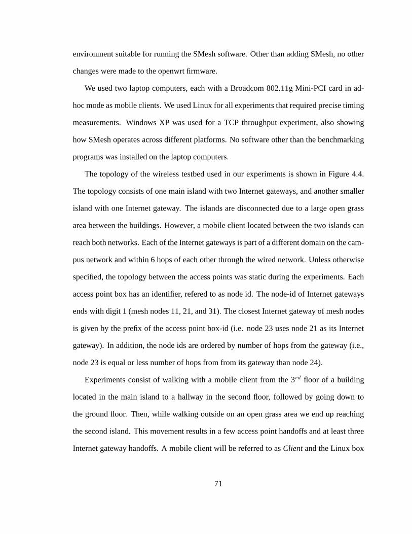
Figure 4.5: P2P Test. Latency of packetsreceived at Moving Client.
0
10
20
30
40
50
60
70
80
90
100
0 2000 4000 6000 8000 10000 12000 14000
110
121
131
141
221
241
251
272
321
Late
ncy
(ms)
Nod
e ID
hop
s
SEQ number
Lost: 13; Duplicate: 0;
packet latency (left axis) currently connected AP (right axis)
Figure 4.6: P2P test. Latency of packetsreceived at Static Client.
0
5
10
15
20
0 2000 4000 6000 8000 10000 12000 14000
110
121
131
141
221
241
251
272
321
Lost
Nod
e ID
hop
s
SEQ number
Lost: 13; Duplicate: 0;
lost packets (left axis) currently connected AP (right axis)
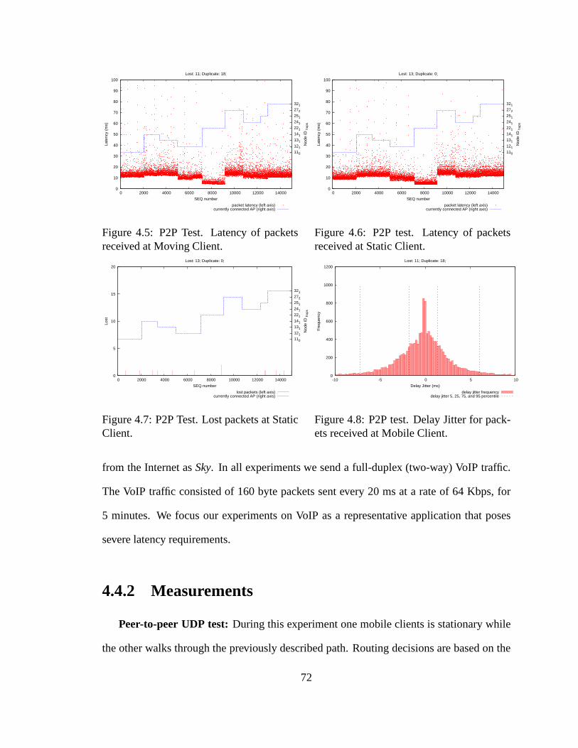
Figure 4.7: P2P Test. Lost packets at StaticClient.
0
200
400
600
800
1000
1200
-10 -5 0 5 10
Fre
quen
cy
Delay Jitter (ms)
Lost: 11; Duplicate: 18;
delay jitter frequencydelay jitter 5, 25, 75, and 95 percentile
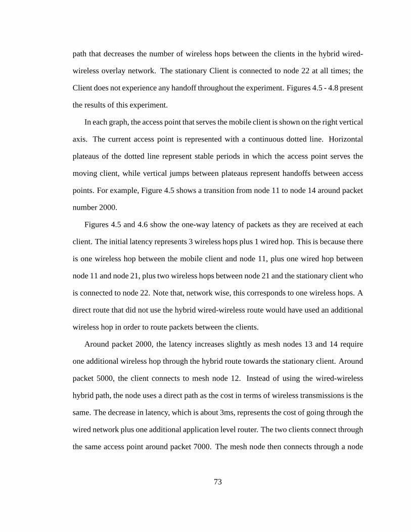
Figure 4.8: P2P test. Delay Jitter for pack-ets received at Mobile Client.
from the Internet asSky. In all experiments we send a full-duplex (two-way) VoIP traffic.
The VoIP traffic consisted of 160 byte packets sent every 20 msat a rate of 64 Kbps, for
5 minutes. We focus our experiments on VoIP as a representative application that poses
severe latency requirements.
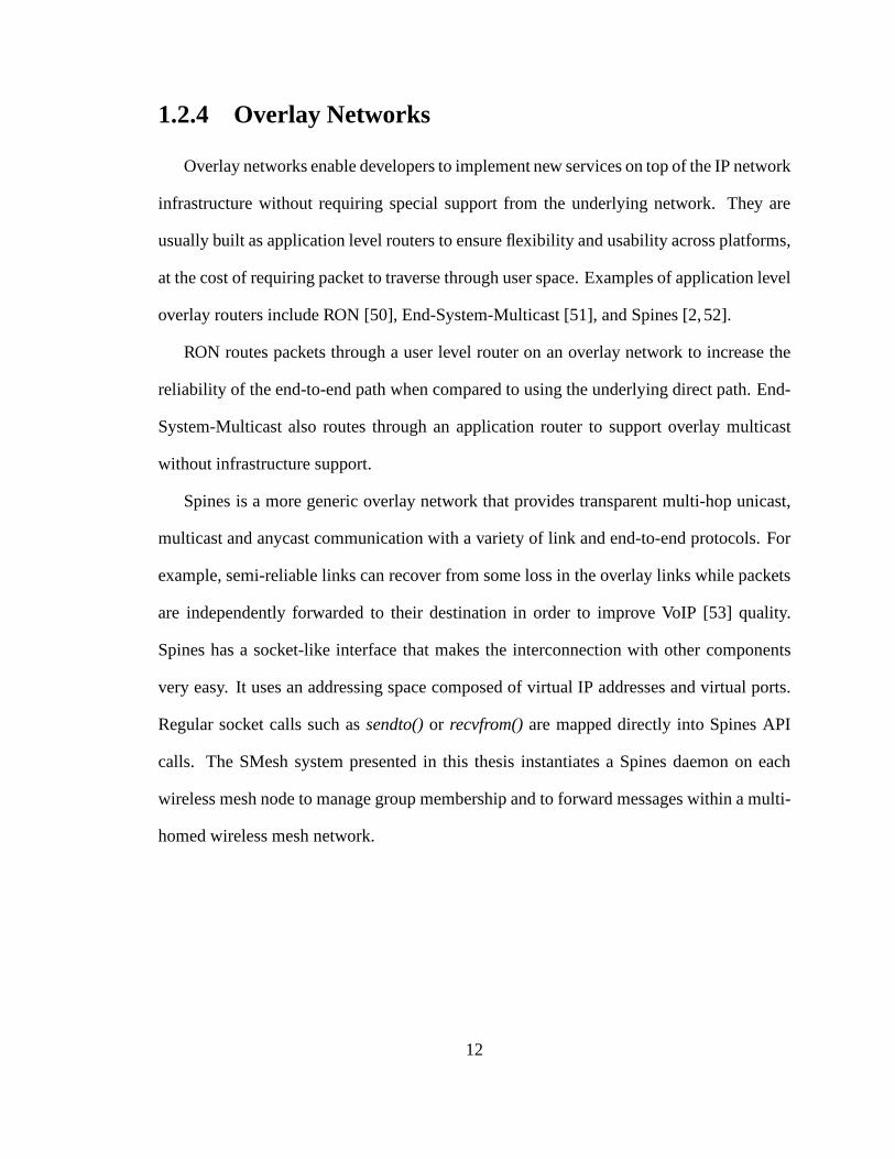
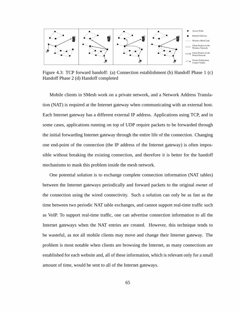
4.4.2 Measurements
Peer-to-peer UDP test: During this experiment one mobile clients is stationary while
the other walks through the previously described path. Routing decisions are based on the
72
path that decreases the number of wireless hops between the clients in the hybrid wired-
wireless overlay network. The stationary Client is connected to node 22 at all times; the
Client does not experience any handoff throughout the experiment. Figures 4.5 - 4.8 present
the results of this experiment.
In each graph, the access point that serves the mobile clientis shown on the right vertical
axis. The current access point is represented with a continuous dotted line. Horizontal
plateaus of the dotted line represent stable periods in which the access point serves the
moving client, while vertical jumps between plateaus represent handoffs between access
points. For example, Figure 4.5 shows a transition from node11 to node 14 around packet
number 2000.
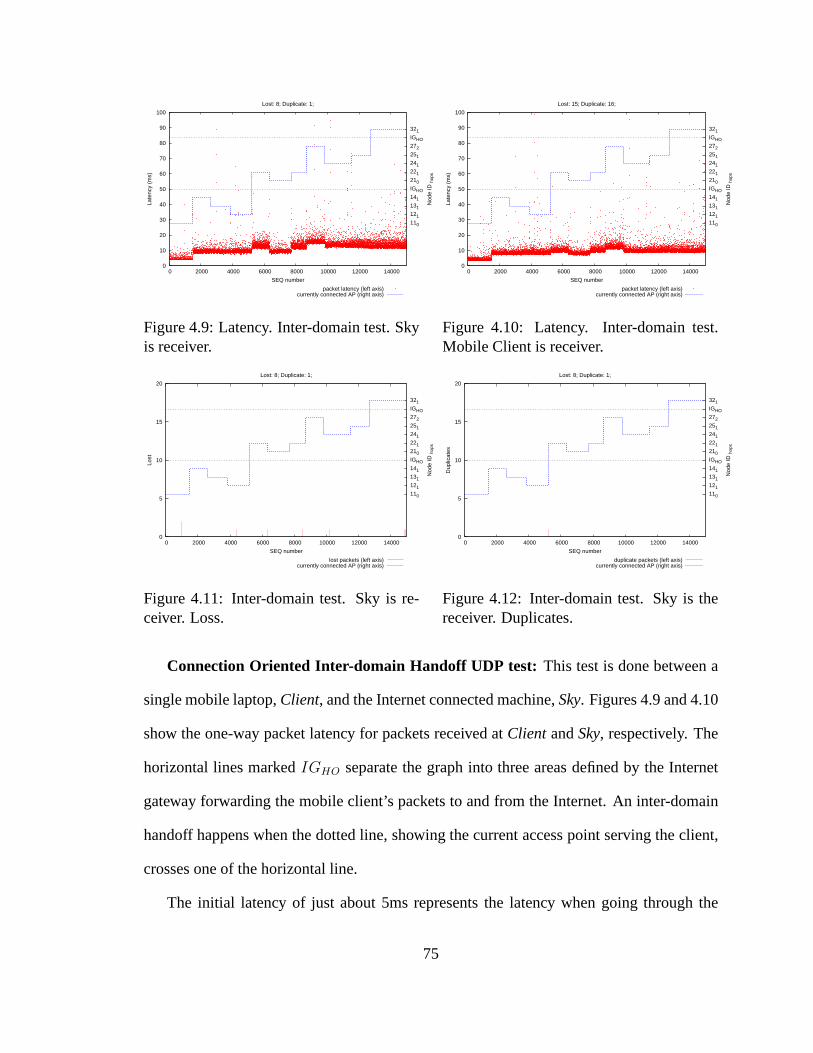
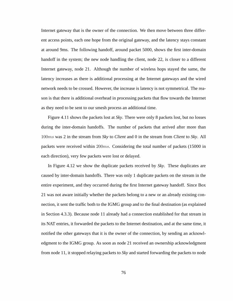
Figures 4.5 and 4.6 show the one-way latency of packets as they are received at each
client. The initial latency represents 3 wireless hops plus1 wired hop. This is because there
is one wireless hop between the mobile client and node 11, plus one wired hop between
node 11 and node 21, plus two wireless hops between node 21 andthe stationary client who
is connected to node 22. Note that, network wise, this corresponds to one wireless hops. A
direct route that did not use the hybrid wired-wireless route would have used an additional
wireless hop in order to route packets between the clients.
Around packet 2000, the latency increases slightly as mesh nodes 13 and 14 require
one additional wireless hop through the hybrid route towards the stationary client. Around
packet 5000, the client connects to mesh node 12. Instead of using the wired-wireless
hybrid path, the node uses a direct path as the cost in terms ofwireless transmissions is the
same. The decrease in latency, which is about 3ms, represents the cost of going through the
wired network plus one additional application level router. The two clients connect through
the same access point around packet 7000. The mesh node then connects through a node
73
that is two direct wireless hops away, and then one wireless hop away, until packet 13000.
Then, the mobile client moves to a node that resides in a different island, and must use the
hybrid path to reach the stationary client. Note that the latency is similar to the one at the
beginning of the experiment, where a different overlay linkthrough the wired network was
used to forward packets to the stationary client.
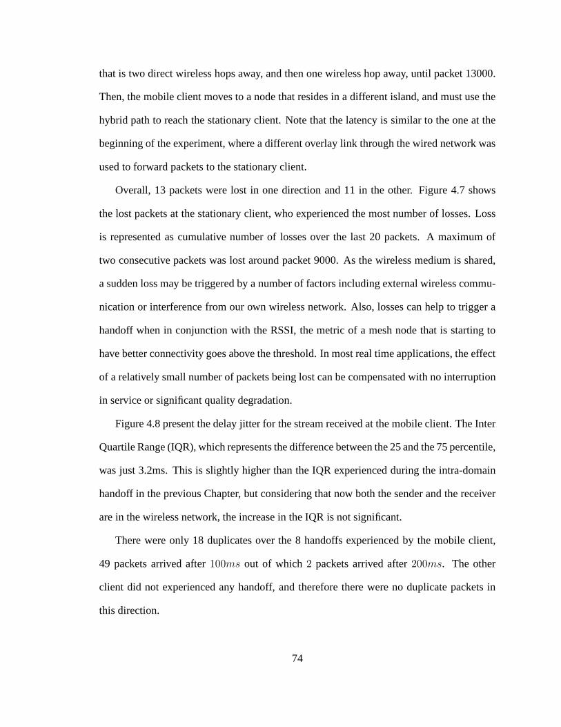
Overall, 13 packets were lost in one direction and 11 in the other. Figure 4.7 shows
the lost packets at the stationary client, who experienced the most number of losses. Loss
is represented as cumulative number of losses over the last 20 packets. A maximum of
two consecutive packets was lost around packet 9000. As the wireless medium is shared,
a sudden loss may be triggered by a number of factors including external wireless commu-
nication or interference from our own wireless network. Also, losses can help to trigger a
handoff when in conjunction with the RSSI, the metric of a mesh node that is starting to
have better connectivity goes above the threshold. In most real time applications, the effect
of a relatively small number of packets being lost can be compensated with no interruption
in service or significant quality degradation.
Figure 4.8 present the delay jitter for the stream received at the mobile client. The Inter
Quartile Range (IQR), which represents the difference between the 25 and the 75 percentile,
was just 3.2ms. This is slightly higher than the IQR experienced during the intra-domain
handoff in the previous Chapter, but considering that now both the sender and the receiver
are in the wireless network, the increase in the IQR is not significant.
There were only 18 duplicates over the 8 handoffs experienced by the mobile client,
49 packets arrived after100ms out of which2 packets arrived after200ms. The other
client did not experienced any handoff, and therefore therewere no duplicate packets in
this direction.
74
0
10
20
30
40
50
60
70
80
90
100
0 2000 4000 6000 8000 10000 12000 14000
110
121
131
141
IGHO
210
221
241
251
272
IGHO
321
Late
ncy
(ms)
Nod
e ID
hop
s
SEQ number
Lost: 8; Duplicate: 1;
packet latency (left axis) currently connected AP (right axis)