69
Seattle Cisco Users Group CCNA Lab Project #3 Joe Rinehart MBA, CCIE #14256 CCNP/DP/VP June 10, 2011

Seattle Cisco Users Group CCNA Lab Project #3
Joe Rinehart
MBA, CCIE #14256
CCNP/DP/VP
June 10, 2011

Table of Contents
1. Introduction .................................................................................................................................... 3
1.1. The CCNA Certification ............................................................................................................ 3
1.2. Purpose of the Lab Project ..................................................................................................... 3
1.3. Overview ...................................................................................................................................... 4
1.4. Basic Topology ........................................................................................................................... 4
1.5. Lab Access .................................................................................................................................... 4
2. Lab Exercises ................................................................................................................................... 6
2.1. Initial Configuration Tasks .................................................................................................... 6
2.2. Local Device Interface Configuration Tasks .................................................................... 7
2.3. Routing Protocol Configuration Tasks .............................................................................. 9
2.4. Network Address Translation Tasks ................................................................................11
2.5. Security Configuration Tasks ..............................................................................................11
3. Answer Key ....................................................................................................................................13
3.1. Initial Configuration Tasks ..................................................................................................13
3.2. Local Device Interface Configuration Tasks ..................................................................20
3.3. Routing Protocol Configuration Tasks ............................................................................26
3.4. Network Address Translation Tasks ................................................................................30
3.5. Security Configuration Tasks ..............................................................................................33
4. Final Configurations ...................................................................................................................37
4.1. R1 Configuration .....................................................................................................................37
4.2. R2 Configuration .....................................................................................................................43
4.3. R3 Configuration .....................................................................................................................49
4.4. R4 Configuration .....................................................................................................................56
4.5. SW1 Configuration ..................................................................................................................64

1. Introduction
1.1. The CCNA Certification
Source: http://www.cisco.com/web/learning/le3/le2/le0/le9/learning_certification_type_home.html
The Cisco Certified Network Associate certification has traditionally been the point of
entry for many network engineers into the world of Cisco networking. In 2007, Cisco
created a new entry-level certification entitled the CCENT, or Cisco Certified Entry
Level Technician. To achieve the CCNA certification, candidates must successfully pass
the 640-802 CCNA exam (single exam), or the two Interconnecting Cisco Networking
Devices exams (640-822 and 640-816).
The CCNA certification validates the skill-sets needed to configure and operate medium-
sized routed and/or switched internetworks, including (but not limited to) the following
topic areas:
� Mitigation of basic security threats
� Wireless networking
� Frame-Relay Wide Area Networks
� OSPF/EIGRP/RIPV2 IP Routing
� Virtual Local Area Networks (VLANs)
� Ethernet Local Area Networks
� Access Control Lists (ACL’s)
� Internet Protocol Version 6
1.2. Purpose of the Lab Project
A thorough understanding of networking concepts is the foundation upon which
understanding is essentially built. While theoretical knowledge is important, the
application of that knowledge is equally important, and forms the basis for effective
performance in real-world environments. Early versions of the CCNA-level certification
exams concentrated on factual knowledge, while current exams utilize realistic
scenarios that reflect more “hands on” experiences. To satisfy these types of
requirements, CCNA students need practical, experience-based exercises.

1.3. Overview
The well-known CCIE Lab exam is composed of an eight-hour set of configuration
scenarios designed to test the absolute limits of a candidate’s practical knowledge.
While the tasks do not represent “best-practice” applications, the challenges certainly
demand a thorough knowledge of every technical aspect involved in networking. As the
current exam pass-rates will demonstrate, only the most well-prepared participants will
possess the discipline and skills to successfully complete the exam requirements.
Mirroring the same demands at a level appropriate to the CCNA certification, the CCNA
project seeks to create an environment for hands-on experience necessary to
successfully complete the certification exam environment.
1.4. Basic Topology
The CCNA project involves the use of four routers and three switches to emulate the
complexity of a medium-sized routed and switched network. The topology involves
three separate locations/sites across a simulated Internet VPN Wide Area Network
(WAN) as well as distinct Local Area Networks (LANs). In addition, Internet access is
included at each site to mirror real-world applications.
1.5. Lab Access

The Seattle Cisco Users Group (www.seacug.com) provides study opportunities through
CCNA study groups, usually held twice a year. At present, INX (www.inxi.com, a premier
Cisco Gold Partner), provides Internet-based access to lab equipment designed to satisfy
the requirements of the CCNA project outlined here. An SSL-based clientless Virtual
Private Network (VPN) allows secure access to a lab environment compatible with the
project requirements. The lab is accessible at https://lab.seacug.com and requires
username/password access arranged in advance. The portal appears as follows:

2. Lab Exercises
2.1. Initial Configuration Tasks
The CCNA project requires certain basic configuration information in order to function
properly. These requirements lay the foundation of successful completion of all later
tasks.
2.1.1. Basic Information
All VLAN, IP Addressing, and interface addressing requirements are as follows:
2.1.2. Configure Device Host Names
All devices used in the project require host names as part of the requirements.
Use the following naming conventions:
Routers: RX (X=Site Number)
Switches: SWX (X=Site Number)
Internet Router, Site 3: R4
2.1.3. Configure Device Access

Each device within the overall lab environment has different methods of access
that must be configured and secured accordingly. Configure each access
method as follows:
• Console Access
o Create login process to go directly to privileged mode
o Use password Cisco123
o No requirement to enter a password to access
• AUX Access (router only)
o Create login process to enter exec mode
o Use password Cisco123
o Login required
• VTY Access (telnet/ssh)
o Create login process to enter exec mode
o Use password Cisco123
o Login required
2.1.4. Configure Basic Security Settings
All devices within a network must implement certain basic security settings in
order to ensure consistent operation. Configure these settings as follows:
• Enable Secret
o Cisco devices require a second password to enter privileged
mode, which can be enable (not encrypted) or enable secret
(encrypted)
o Set the enable secret password to Cisco123
o Do not set the enable (non-encrypted) password
• Secure telnet/ssh access
o Create an access-list to telnet access from outside the network
but permit ssh from outside the network
o Apply the access list in the appropriate location on all devices
2.1.5. Configure Other Basic Device Settings
Specific device settings can simplify management and operation within the
network. Configure these settings as follows:
• Set clocks on all devices to Pacific Time, including Daylight Savings Time
settings
• Disable devices from using DNS lookups
• Enable web-based access on all devices and set to port 8080
• Set login message to “Welcome to the CCNA VPN Lab!”
• Set all devices to update their clocks based on the time configured on
R4
2.2. Local Device Interface Configuration Tasks

Every networking device in the environment has multiple interfaces that require specific
configuration tasks in order to provide connectivity to resources.
2.2.1. VLAN Interfaces
All sites have multiple VLAN segments that require configuration to be applied
on the LAN switch as well as the site router. Configure the following VLANs at
each site in the topology:
• Management VLAN: Used for managing all remote devices by resources
at the central data center (R1/R2/R3 Only)
o Set the VLAN ID to X (X=Site Number)
o Name the VLAN MANAGEMENT VLAN
o Create IP addressing to allow for 4 usable Hosts
• Production VLAN: Used for normal network operations
o Set the VLAN ID to XX (X=Site Number)
o Name the VLAN PRODUCTION VLAN
o Create IP addressing to allow for 32 usable Hosts
o Add R4 to R3’s Production VLAN
• Internet VLAN: Used for providing Internet access through the Internet
connection at all sites
o Set the VLAN ID to 99
o Name the VLAN INTERNET VLAN
o Create IP addressing to allow for 4 usable Hosts
2.2.2. Loopback Interfaces
Loopback interfaces are logical interfaces that do not go down unless the device
itself is no longer operational. Tying device processes to loopback interfaces
prevent intermittent issues resulting from links going up and down.
• Create a loopback interface for each router in the network
• Assign the name Loopback 0 to each loopback interface
• Assign IP subnet for a single host: 10.Y.Y.Y (Y=device number)
2.2.3. GRE VPN WAN Interfaces
WAN connectivity between sites is provided through a VPN. Configure VPN
access on the Internet interfaces as follows:

• Create a full-mesh tunnel configuration between all sites
• Specify GRE IP Encapsulation for the tunnels
• Specify the source as Fa0/0.99
• Specify the destination using the Internet VLAN address of the
neighboring router
• Assign IP addresses per diagram, with 8 usable hosts per subnet
2.2.4. Internet WAN Interfaces
All sites receive their Internet access locally through an Ethernet handoff:
• Create subinterfaces using 99 as the reference number reference (e.g.,
FastEthernet 0/0.99)
• Specify ISL (R1/R2/R3) or 802.1Q (R4) Trunking Encapsulation and 99 as
the VLAN ID
• Assign IP addresses per diagram, with 6 usable hosts per subnet
2.3. Routing Protocol Configuration Tasks
Multiple routing protocols are in use throughout the network and require careful
configuration to ensure correct operation. Refer to the following diagram as a reference
point:
SEACUG CCNA Study GroupCCNA Lab Project
EIGRP
Internet
Site 1
Site 2
Site 3
R1
SW1
R3
SW2
SW3
R2
R4
GRE
RIP V2
OSPF
2.3.1. EIGRP Configuration
EIGRP is the primary routing configuration in use throughout the network, and
must be operational at all three sites. Configure EIGRP routing as follows:

• R1 EIGRP Configuration
o Use AS Number 1003
o Enable EIGRP on all GRE tunnel interfaces
o Disable auto summarization
• R2 EIGRP Configuration
o Use AS Number 1003
o Enable EIGRP on all GRE tunnel interfaces
o Enable EIGRP on Loopback and VLAN interfaces
o Disable auto summarization
• R3 EIGRP Configuration
o Use AS Number 1003
o Enable EIGRP on all GRE tunnel interfaces
o Disable auto summarization
2.3.2. OSPF Configuration
OSPF is running between R3 and R4 for connectivity at a campus location.
Configure routing as follows:
• R3 OSPF Configuration
o Place the Loopback interface in area 3
o Place all local VLAN interfaces in area 3
o Do not specify the router-id
• R4 OSPF Configuration
o Place all local VLAN interfaces and the loopback interface in
area 3
o Do not specify the router-id
2.3.3. Redistribution and Tuning Configuration
With multiple routing protocols in use, full connectivity must be created
between protocols to allow consistent communication. Configure as follows:
• Redistribute EIGRP into OSPF using a route map to ensure only the
internal routes are permitted
• Perform redistribution on R1 so that all RIP interfaces will be accessible
to the EIGRP process
• Do not configure any static routes to accomplish this task
• Verify full reachability:
o Ping all other devices in the network from each device
o Successfully telnet to all devices in the network from each
device
2.4. Network Address Translation Tasks
All sites within the network utilize addressing from the RFC 1918 Private Addressing
space, which are not valid on the Internet. In order to have full Internet connectivity, all
internal addressing must be mapped to globally routable addressing space. In addition,
an internal web server at Site 2 must also be accessible from the Internet
2.4.1. Configure Port Address Translation for All Internal Hosts
Configure Port Address Translation/Overloading on R1,R2, & R3 on the Internet
Interface.
2.4.2. Static Network Address Translation for an Email Server on R2
Email services were previously enabled on R2 and accessible from within the
internal network, but need to be available on the Internet for monitoring and
management purposes. Using static a NAT entry, point email connections to
R2’s Production VLAN address.
2.5. Security Configuration Tasks
Preventing unauthorized access to devices on the network may be supplied in part by
the external ASA firewall, but additional measured need to be implemented to protect
information assets.
2.5.1. Create and apply an access that will only allow internal devices to access the
management VLAN on all devices.
The company’s information security policy stipulates that no users outside of the
company are permitted to access internal resources. To prevent unauthorized access,
disallow all outside users from accessing the hosts within the protected network.
2.5.2. Block outbound SMTP access from all sites
Unsecured (SMTP) emails are a source of security concerns for the management team
and they have elected not to permit it anywhere on the network. Configure the
appropriate packet filters/access-lists to block all SMTP outbound from all sites.

2.5.3. Block outbound TFTP access from Site 2
Site 2 contains sensitive data that must not be sent outside the network, and TFTP is
considered a security risk. Configure the appropriate packet filters/access-lists to block
all TFTP outbound from all sites.
2.5.4. Block all external access trying to reach the management VLAN
Remote access has been provided at the primary corporate location for the purpose of
managing all internal network resources. Because of the sensitive nature of the data at
the corporate locations, external access to the Management VLANs is not permitted by
the security policy. Construct an access list to block any attempt at access from the
Internet interface.

3. Answer Key
The following section outlines detailed, step-by-step solutions to the previous configuration
requirements. This allows students to compare their own devices against the answers, keeping
in mind that some minor differences may exist. In the SEACUG lab environment, for example,
only a single switch is utilized for the topology. Answers are displayed in bold following
restatement of the original configuration tasks.
3.1. Initial Configuration Tasks
3.1.1. Basic Information
All VLAN, IP Addressing, and interface addressing requirements are as follows:
ANSWERS:
All configuration tasks utilize these addressing specifications.
3.1.2. Configure Device Host Names
All devices used in the project require host names as part of the requirements.
Use the following naming conventions:
Routers: RX (X=Site Number)
Switches: SWX (X=Site Number)
Internet Router, Site 3: R4
ANSWERS:

R1
Hostname R1 (lab may already have hostname(s) configured)
R2
Hostname R2 (lab may already have hostname(s) configured)
R3
Hostname R3 (lab may already have hostname(s) configured)
R4
Hostname R4 (lab may already have hostname(s) configured)
SW1
Hostname SW1 (lab may already have hostname(s) configured)
** If using three switches, substitute SW2, SW3, etc. for additional switches **
3.1.3. Configure Device Access
Each device within the overall lab environment has different methods of access
that must be configured and secured accordingly. Configure each access
method as follows:
• Console Access
o Create login process to go directly to privileged mode
o Use password Cisco123
o No requirement to enter a password to access
ANSWERS:
** The privilege level command sets the default permission level available **
** The password command specifies the access password **
** The login command causes a required login process; no login disables it **
R1
line con 0
password cisco
privilege level 15
no login
R2

line con 0
password cisco
privilege level 15
no login
R3
line con 0
password cisco
privilege level 15
no login
R4
line con 0
password cisco
privilege level 15
no login
SW1
line con 0
password cisco
privilege level 15
no login
** If using three switches, duplicate configuration for additional switches **
• AUX Access (router only)
o Create login process to enter exec mode
o Use password Cisco123
o Login required
ANSWERS:
** The password command specifies the access password **
** The login command causes a required login process; no login disables it **
R1
line aux 0
password cisco
login
R2
line aux 0
password cisco
login

R3
line aux 0
password cisco
login
R4
line aux 0
password cisco
login
• VTY Access (telnet/ssh)
o Create login process to enter exec mode
o Use password Cisco123
o Login required
ANSWERS:
** Available VTY lines vary by device, each of which is configurable separately**
** Programming multiple VTY requires specifying the range, the 2620 has 181 **
** The login command causes a required login process; no login disables it **
R1
line vty 0 181
password Cisco123
login
R2
line vty 0 181
password Cisco123
login
R3
line vty 0 181
password Cisco123
login
R4
line vty 0 988
password Cisco123
login

SW1
line vty 0 15
password Cisco123
login
** If using three switches, duplicate configuration for additional switches **
3.1.4. Configure Basic Security Settings
All devices within a network must implement certain basic security settings in
order to ensure consistent operation. Configure these settings as follows:
• Enable Secret
o Cisco devices require a second password to enter privileged
mode, which can be enable (not encrypted) or enable secret
(encrypted)
o Set the enable secret password to Cisco123
o Do not set the enable (non-encrypted) password
ANSWERS:
** The enable secret command encrypts the password even in the configuration **
** Remember that the passwords you specify are case sensitive **
R1
Enable secret Cisco123
R2
Enable secret Cisco123
R3
Enable secret Cisco123
R4
Enable secret cisco
SW1
Enable secret Cisco123
** If using three switches, duplicate configuration for additional switches **
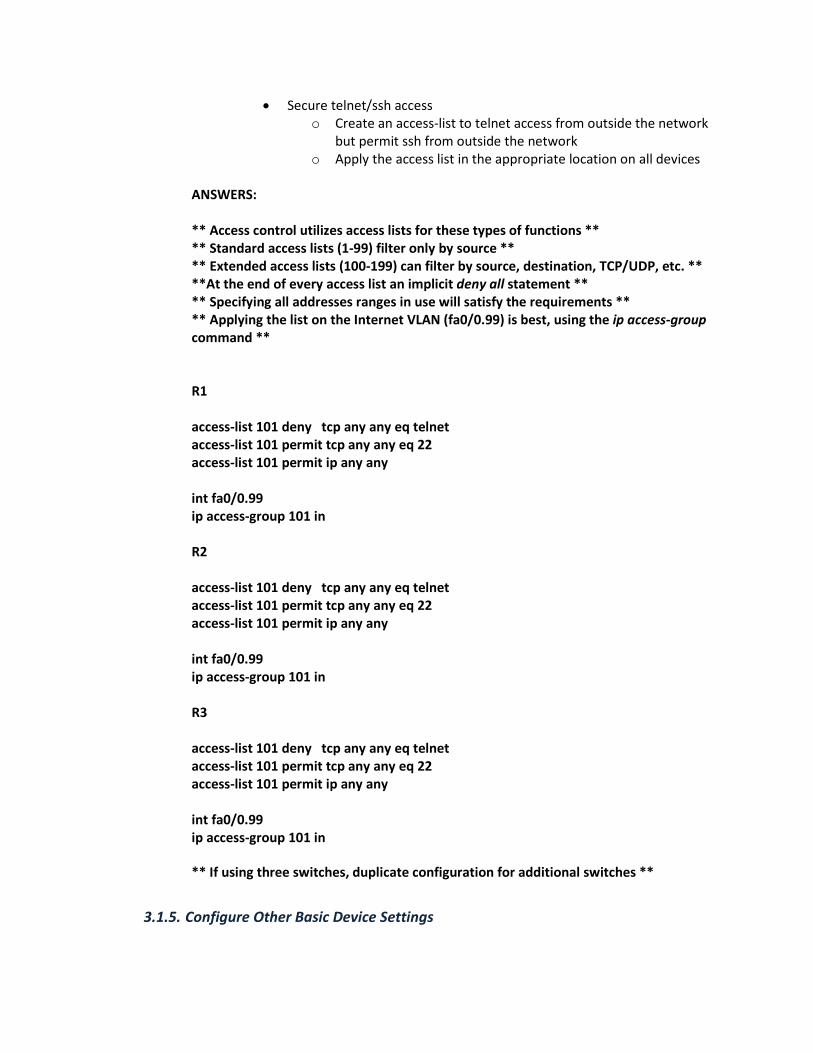
• Secure telnet/ssh access
o Create an access-list to telnet access from outside the network
but permit ssh from outside the network
o Apply the access list in the appropriate location on all devices
ANSWERS:
** Access control utilizes access lists for these types of functions **
** Standard access lists (1-99) filter only by source **
** Extended access lists (100-199) can filter by source, destination, TCP/UDP, etc. **
**At the end of every access list an implicit deny all statement **
** Specifying all addresses ranges in use will satisfy the requirements **
** Applying the list on the Internet VLAN (fa0/0.99) is best, using the ip access-group
command **
R1
access-list 101 deny tcp any any eq telnet
access-list 101 permit tcp any any eq 22
access-list 101 permit ip any any
int fa0/0.99
ip access-group 101 in
R2
access-list 101 deny tcp any any eq telnet
access-list 101 permit tcp any any eq 22
access-list 101 permit ip any any
int fa0/0.99
ip access-group 101 in
R3
access-list 101 deny tcp any any eq telnet
access-list 101 permit tcp any any eq 22
access-list 101 permit ip any any
int fa0/0.99
ip access-group 101 in
** If using three switches, duplicate configuration for additional switches **
3.1.5. Configure Other Basic Device Settings

Specific device settings can simplify management and operation within the
network. Configure these settings as follows:
• Set clocks on all devices to Pacific Time, including Daylight Savings Time
settings
• Disable devices from using DNS lookups
• Enable web-based access on all devices and set to port 8080
• Set login message to “Welcome to the CCNA VPN Lab!”
• Set all devices to update their clocks based on the time configured on
R4
ANSWERS:
** Setting the system clock is one function done from the command line, not global
configuration mode, using the set clock timezone command **
** Disabling DNS lookups on a device is helpful especially f you mistype a command.
The no ip domain-lookup command disables this function**
** Web-based device access is another way to program/monitor devices,
with other settings as well. The ip http server command enables this. Setting
a non-default port is accomplished using the ip http port command**
** Displaying a welcome message is another helpful functional that should be used
whenever possible. The “message of the day” is configured using the
command banner motd, with the # symbol acting as delimiters **
R1
clock timezone PST -8
clock summer-time PDT date Mar 13 2011 2:00 Nov 6 2011 2:00
no ip domain lookup
banner motd #Welcome to the CCNA VPN Lab!#
ntp server 10.99.99.4
R2
clock timezone PST -8
clock summer-time PDT date Mar 13 2011 2:00 Nov 6 2011 2:00
no ip domain lookup
banner motd #Welcome to the CCNA VPN Lab!#
ntp server 10.99.99.4
R3
clock timezone PST -8
clock summer-time PDT date Mar 13 2011 2:00 Nov 6 2011 2:00
no ip domain lookup
banner motd #Welcome to the CCNA VPN Lab!#
ntp server 10.99.99.4

R4
ntp master
no ip domain lookup
banner motd #Welcome to the CCNA VPN Lab!#
SW1
clock timezone PST -8
clock summer-time PDT date Mar 13 2011 2:00 Nov 6 2011 2:00
no ip domain lookup
banner motd #Welcome to the CCNA VPN Lab!#
ntp server 10.99.99.4
** If using three switches, duplicate configuration for additional switches **
3.2. Local Device Interface Configuration Tasks
Every networking device in the environment has multiple interfaces that require specific
configuration tasks in order to provide connectivity to resources.
3.2.1. VLAN Interfaces
All sites have multiple VLAN segments that require configuration to be applied
on the LAN switch as well as the site router. Configure the following VLANs at
each site in the topology:
ANSWERS:
** Both the routers and switch(es) require separate and distinct configuration for
creating and processing VLANs. The following outline demonstrates the
switch portion of the configuration **
SW1
First, VLANs must be configured from global configuration mode:
vlan 11
vlan 2
vlan 22
vlan 3
vlan 33
vlan 99
To support multiple VLANs, the ports on the switch(es) must be configured for
trunking on the connection to the routers:

interface fa0/2
switchport trunk encapsulation dot1q
switchport mode trunk
description Trunk to R1
interface fa0/1
switchport trunk encapsulation dot1q
switchport mode trunk
description Trunk to R2
interface fa0/3
switchport trunk encapsulation dot1q
switchport mode trunk
description Trunk to R3
interface fa0/8
switchport trunk encapsulation dot1q
switchport mode trunk
description Trunk to R4
** If using three switches, duplicate configuration for additional switches **
• Management VLAN: Used for managing all remote devices by resources
at the central data center
o Set the VLAN ID to X (X=Site Number)
o Name the VLAN MANAGEMENT VLAN
o Create IP addressing to allow for 4 usable Hosts
ANSWERS:
** VLAN configuration on a router interface requires the use of subinterfaces for each
configured VLAN. The encapsulation type and VLAN ID/number must also be
specified on the subinterface **
** Choices for an IP subnet depend on the numbers of networks and hosts needed to
satisfy requirements. For the Management VLAN, one network is needed, but
5 usable hosts. Subnets could include 192.168.X.0 255.255.255.240 (or
/28), but that yields 30 usable hosts (too many). 192.168.X.0 255.255.255.248
(or /29) gives 6 usable hosts, which is a better choice **
R1
interface fa0/0.1
description Management VLAN
encapsulation isl 1
ip address 192.168.1.1 255.255.255.248
R2
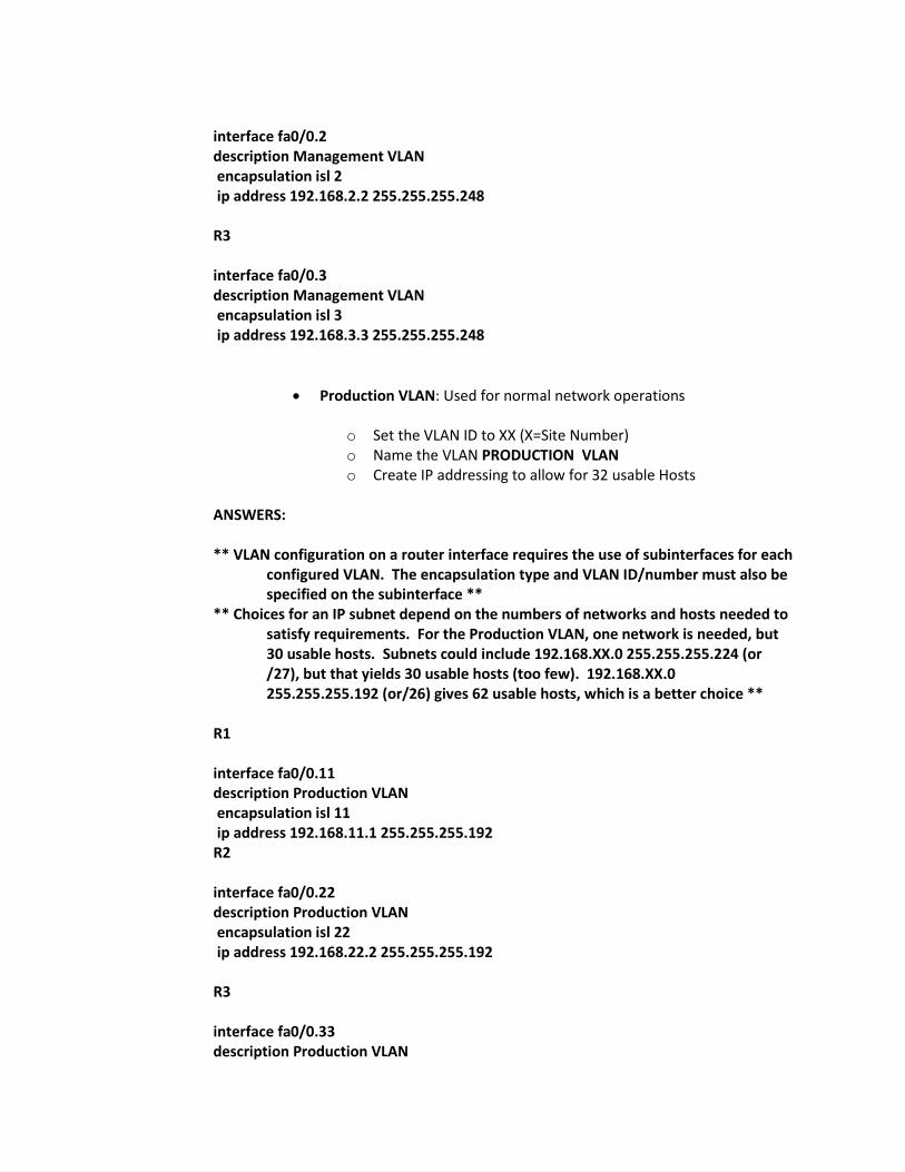
interface fa0/0.2
description Management VLAN
encapsulation isl 2
ip address 192.168.2.2 255.255.255.248
R3
interface fa0/0.3
description Management VLAN
encapsulation isl 3
ip address 192.168.3.3 255.255.255.248
• Production VLAN: Used for normal network operations
o Set the VLAN ID to XX (X=Site Number)
o Name the VLAN PRODUCTION VLAN
o Create IP addressing to allow for 32 usable Hosts
ANSWERS:
** VLAN configuration on a router interface requires the use of subinterfaces for each
configured VLAN. The encapsulation type and VLAN ID/number must also be
specified on the subinterface **
** Choices for an IP subnet depend on the numbers of networks and hosts needed to
satisfy requirements. For the Production VLAN, one network is needed, but
30 usable hosts. Subnets could include 192.168.XX.0 255.255.255.224 (or
/27), but that yields 30 usable hosts (too few). 192.168.XX.0
255.255.255.192 (or/26) gives 62 usable hosts, which is a better choice **
R1
interface fa0/0.11
description Production VLAN
encapsulation isl 11
ip address 192.168.11.1 255.255.255.192
R2
interface fa0/0.22
description Production VLAN
encapsulation isl 22
ip address 192.168.22.2 255.255.255.192
R3
interface fa0/0.33
description Production VLAN

encapsulation isl 33
ip address 192.168.33.3 255.255.255.192
• Internet VLAN: Used for providing Internet access through the Internet
connection at Site 3 (R3/R4)
o Set the VLAN ID to 99
o Name the VLAN INTERNET VLAN
o Create IP addressing to allow for 4 usable Hosts
ANSWERS:
** VLAN configuration on a router interface requires the use of subinterfaces for each
configured VLAN. The encapsulation type and VLAN ID/number must also be
specified on the subinterface. **
R1
interface fa0/0.99
description Internet VLAN
encapsulation isl 99
ip address 10.99.99.1 255.255.255.248
R2
interface fa0/0.99
description Internet VLAN
encapsulation isl 99
ip address 10.99.99.2 255.255.255.248
R3
interface fa0/0.99
description Internet VLAN
encapsulation isl
ip address 10.99.99.3 255.255.255.248
R4
interface fa0/0.99
description Internet VLAN
encapsulation dot1q 99
ip address 10.99.99.4 255.255.255.248
3.2.2. Loopback Interfaces (R1/R2/R3 Only)

Loopback interfaces are logical interfaces that do not go down unless the device
itself is no longer operational. Tying device processes to loopback interfaces
prevent intermittent issues resulting from links going up and down.
• Create a loopback interface for each router in the network
• Assign the name Loopback 0 to each loopback interface
• Assign IP subnet for a single host: 10.Y.Y.Y (Y=device number)
ANSWERS:
R1
interface Loopback0
description Loopback Interface
ip address 10.1.1.1 255.255.255.255
R2
interface Loopback0
description Loopback Interface
ip address 10.2.2.2 255.255.255.255
R3
interface Loopback0
description Loopback Interface
ip address 10.3.3.3 255.255.255.255
3.2.3. GRE Interfaces (R1/R2/R3 Only)
Backup network connectivity is required in the event of failure on the Metro-E
service. Configure VPN access on the Internet interfaces as follows:
• Create a full-mesh tunnel configuration between all sites
• Specify GRE IP Encapsulation for the tunnels
• Enable CDP on the tunnels
• Specify the source as Fa0/0.99
• Specify the destination using the Internet VLAN address of the
neighboring router
• Assign IP addresses per diagram, with 8 usable hosts per subnet
ANSWERS:
** Generic Routing Encapsulation (GRE) is used to tunnel non-IP protocols through an
IP environment, and also frequently used in VPN configurations. In a

production setting, the addition of IPSec encryption would be necessary to
address security concerns **
** Tunnel interfaces require specifying source and destination endpoints in addition
to standard interface commands **
R1
interface Tunnel12
description VPN INTERFACE to R2
ip address 172.16.12.1 255.255.255.240
tunnel source 10.99.99.1
tunnel destination 10.99.99.2
interface Tunnel13
description VPN INTERFACE to R3
ip address 172.16.13.1 255.255.255.240
tunnel source 10.99.99.1
tunnel destination 10.99.99.3
R2
interface Tunnel12
description VPN INTERFACE to R1
ip address 172.16.12.2 255.255.255.240
tunnel source 10.99.99.2
tunnel destination 10.99.99.1
interface Tunnel23
description VPN INTERFACE to R2
ip address 172.16.23.2 255.255.255.240
tunnel source 10.99.99.2
tunnel destination 10.99.99.3
R3
interface Tunnel13
description VPN INTERFACE to R2
ip address 172.16.23.3 255.255.255.240
tunnel source 10.99.99.3
tunnel destination 10.99.99.1
interface Tunnel23
description VPN INTERFACE to R1
ip address 172.16.13.3 255.255.255.240
tunnel source 10.99.99.3
tunnel destination 10.99.99.1

3.3. Routing Protocol Configuration Tasks
Multiple routing protocols are in use throughout the network and require careful
configuration to ensure correct operation. Refer to the following diagram as a reference
point:
SEACUG CCNA Study GroupCCNA Lab Project
EIGRP
Internet
Site 1
Site 2
Site 3
R1
SW1
R3
SW2
SW3
R2
R4
GRE
RIP V2
OSPF
3.3.1. EIGRP Configuration
EIGRP is the primary routing configuration in use throughout the network, and
must be operational at all three sites. Configure EIGRP routing as follows:
• R1 EIGRP Configuration
o Use AS Number 1003
o Enable EIGRP on all GRE tunnel interfaces
o Disable auto summarization
ANSWERS:
**EIGRP is configured from router configuration mode, which is entered by the
command router eigrp <as-number> **
** Interfaces are placed in EIGRP using the network command, using the best practice
of the most specific subnets possible **
** Automatic network summarization is on by default **
R1

router eigrp 1003
network 172.16.12.0 0.0.0.15
network 172.16.13.0 0.0.0.15
no auto-summary
• R2 EIGRP Configuration
o Use AS Number 1003
o Enable EIGRP on all GRE tunnel interfaces
o Enable EIGRP on Loopback and VLAN interfaces
o Disable auto summarization
ANSWERS:
**EIGRP is configured from router configuration mode, which is entered by the
command router eigrp <as-number> **
** Interfaces are placed in EIGRP using the network command, using the best practice
of the most specific subnets possible **
** Automatic network summarization is on by default **
R2
router eigrp 1003
network 10.2.2.2 0.0.0.0
network 172.16.12.0 0.0.0.15
network 172.16.23.0 0.0.0.15
network 192.168.2.0 0.0.0.7
network 192.168.22.0 0.0.0.31
no auto-summary
• R3 EIGRP Configuration
o Use AS Number 111
o Enable EIGRP on all GRE tunnel interfaces
o Disable auto summarization
ANSWERS:
**EIGRP is configured from router configuration mode, which is entered by the
command router eigrp <as-number> **
** Interfaces are placed in EIGRP using the network command, using the best practice
of the most specific subnets possible **
** Automatic network summarization is on by default **
R3
router eigrp 1003
network 172.16.13.0 0.0.0.7

network 172.16.23.0 0.0.0.7
no auto-summary
3.3.2. OSPF Configuration
OSPF is running between R3 and R4 for connectivity at a campus location.
Configure routing as follows:
• R3 OSPF Configuration
o Place the Loopback interface in area 3
o Place all local VLAN interfaces in area 3
o Do not specify the router-id
ANSWERS:
**OSPF is configured from router configuration mode, which is entered by the
command router ospf <process-id> **
** Interfaces are placed in OSPF using the network command, using the best practice
of the most specific subnets possible. The loopback and VLAN interfaces
should be placed in area 3, and since there is only a single area no area 0 is
required **
R3
router ospf 1
log-adjacency-changes
network 10.3.3.3 0.0.0.0 area 3
network 172.168.3.0 0.0.0.7 area 3
network 192.168.33.0 0.0.0.31 area 3
• R4 OSPF Configuration
o Set Loopback 0 as the OSPF router-id
o Place the Metro Ethernet interface in area 0
o Place all local VLAN interfaces and the loopback interface in
area 2
ANSWERS:
** OSPF is configured from router configuration mode, which is entered by the
command router ospf <process-id> **
** Interfaces are placed in OSPF using the network command, using the best practice
of the most specific subnets possible. The loopback and VLAN interfaces
should be placed in area 3, and since there is only a single area no area 0 is
required **

R4
router ospf 1
router-id 10.4.4.4
log-adjacency-changes
network 10.4.4.4 0.0.0.0 area 3
network 192.168.33.0 0.0.0.7 area 3
3.3.3. Redistribution and Tuning Configuration
With multiple routing protocols in use, full connectivity must be created
between protocols to allow consistent communication. Configure as follows:
• Redistribute EIGRP into OSPF using a route map to ensure only the
internal routes are permitted
• Perform redistribution on R1 so that all RIP interfaces will be accessible
to the EIGRP process
• Do not configure any static routes to accomplish this task
• Verify full reachability:
o Ping all other devices in the network from each device
o Successfully telnet to all devices in the network from each
device
ANSWERS:
R1
router eigrp 1003
redistribute rip metric 1544 10 128 128 1500
R3
access-list 3 permit 192.168.0.0 0.0.255.255
access-list 3 permit 172.16.0.0 0.0.255.255
route-map Redistribute-Selective permit 10
match ip address 3
router eigrp 1003
redistribute connected
router ospf 1
log-adjacency-changes
redistribute eigrp 1003 metric-type 1 subnets route-map Redistribute-Selective
• Verify full reachability:

o Ping all other devices in the network from each device
o Successfully telnet to all devices in the network from each
device
R1 Routing Table During Steady State Operations
R1#sh ip route
Codes: C - connected, S - static, R - RIP, M - mobile, B - BGP
D - EIGRP, EX - EIGRP external, O - OSPF, IA - OSPF inter area
N1 - OSPF NSSA external type 1, N2 - OSPF NSSA external type 2
E1 - OSPF external type 1, E2 - OSPF external type 2
i - IS-IS, su - IS-IS summary, L1 - IS-IS level-1, L2 - IS-IS level-2
ia - IS-IS inter area, * - candidate default, U - per-user static route
o - ODR, P - periodic downloaded static route
Gateway of last resort is 10.99.99.4 to network 0.0.0.0
172.16.0.0/28 is subnetted, 3 subnets
D 172.16.23.0 [90/310044416] via 172.16.12.2, 1d14h, Tunnel12
[90/310044416] via 172.16.13.3, 1d14h, Tunnel13
C 172.16.12.0 is directly connected, Tunnel12
C 172.16.13.0 is directly connected, Tunnel13
192.168.11.0/26 is subnetted, 1 subnets
C 192.168.11.0 is directly connected, FastEthernet0/0.11
10.0.0.0/8 is variably subnetted, 4 subnets, 2 masks
D 10.2.2.2/32 [90/297372416] via 172.16.12.2, 1d14h, Tunnel12
D EX 10.3.3.3/32 [170/297372416] via 172.16.13.3, 13:36:14, Tunnel13
C 10.99.99.0/29 is directly connected, FastEthernet0/0.99
C 10.1.1.1/32 is directly connected, Loopback0
192.168.22.0/26 is subnetted, 1 subnets
D 192.168.22.0 [90/297246976] via 172.16.12.2, 1d14h, Tunnel12
192.168.1.0/29 is subnetted, 1 subnets
C 192.168.1.0 is directly connected, FastEthernet0/0.1
192.168.2.0/29 is subnetted, 1 subnets
D 192.168.2.0 [90/297246976] via 172.16.12.2, 1d14h, Tunnel12
192.168.3.0/29 is subnetted, 1 subnets
D EX 192.168.3.0 [170/297246976] via 172.16.13.3, 13:36:20, Tunnel13
192.168.33.0/26 is subnetted, 1 subnets
D EX 192.168.33.0 [170/297246976] via 172.16.13.3, 13:36:20, Tunnel13
S* 0.0.0.0/0 [1/0] via 10.99.99.4
3.4. Network Address Translation Tasks
All sites within the network utilize addressing from the RFC 1918 Private Addressing
space, which are not valid on the Internet. In order to have full Internet connectivity, all
internal addressing must be mapped to globally routable addressing space. In addition,
an internal web server must also be accessible from the Internet

3.4.1. Configure Port Address Translation for All Internal Hosts
Configure Port Address Translation/Overloading on R1, R2, & R3 on the Internet
Interface.
ANSWERS:
**PAT or IP Address Overloading has several steps for successful configuration:
1. Create an access-list identifying the addresses to be translated
2. Identify the inside and outside interfaces (ip nat inside or outside)
3. Map the access-list to the outside interface using the ip nat inside source
list statement**
R1
access-list 1 permit 10.1.1.1
access-list 1 permit 192.168.1.0 0.0.0.7
access-list 1 permit 192.168.11.0 0.0.0.63
access-list 1 permit 172.16.12.0 0.0.0.15
access-list 1 permit 172.16.13.0 0.0.0.15
access-list 1 deny any
interface Loopback0
ip nat inside
interface Tunnel12
ip nat inside
interface Tunnel13
ip nat inside
interface FastEthernet0/0.1
ip nat inside
interface FastEthernet0/0.11
ip nat inside
interface FastEthernet0/0.99
ip nat outside
ip nat inside source list 1 interface FastEthernet0/0.99 overload
R2
access-list 1 permit 10.2.2.2
access-list 1 permit 192.168.2.0 0.0.0.7
access-list 1 permit 192.168.22.0 0.0.0.63

access-list 1 permit 172.16.12.0 0.0.0.15
access-list 1 permit 172.16.23.0 0.0.0.15
access-list 1 deny any
interface Loopback0
ip nat inside
interface Tunnel12
ip nat inside
interface Tunnel23
ip nat inside
interface FastEthernet0/0.2
ip nat inside
interface FastEthernet0/0.22
ip nat inside
interface FastEthernet0/0.99
ip nat outside
ip nat inside source list 1 interface FastEthernet0/0.99 overload
R3
access-list 1 permit 10.3.3.3
access-list 1 permit 192.168.3.0 0.0.0.7
access-list 1 permit 192.168.3.0 0.0.0.63
access-list 1 permit 172.16.13.0 0.0.0.15
access-list 1 permit 172.16.23.0 0.0.0.15
access-list 1 deny any
interface Loopback0
ip nat inside
interface Tunnel13
ip nat inside
interface Tunnel23
ip nat inside
interface FastEthernet0/0.3
ip nat inside
interface FastEthernet0/0.33
ip nat inside

interface FastEthernet0/0.99
ip nat outside
ip nat inside source list 1 interface FastEthernet0/0.99 overload
3.4.2. Static Network Address Translation for an SMTP Mail Server on R2
Email services were previously enabled on R2 and accessible from within the
internal network, but need to be available on the Internet for monitoring and
management purposes. Using static a NAT entry, point email connections to
R2’s Production VLAN address.
ANSWERS:
**Static NAT configuration uses a variation of the ip nat inside statement but applies it
to only a single service, including IP, TCP and UDP **
R2
** Mapping the email server uses a static NAT configuration as follows: **
ip nat inside source static tcp 192.168.22.1 25 interface FastEthernet0/0.99 25
3.5. Security Configuration Tasks
Preventing unauthorized access to devices on the network may be supplied in part by
the external ASA firewall, but additional measured need to be implemented to protect
information assets.
3.5.1. Create and apply an access that will only allow internal devices to access the
management VLAN on all devices at each site.
The company’s information security policy stipulates that no users outside of the
company are permitted to access internal resources. To prevent unauthorized access,
disallow all outside users from accessing the hosts within the protected network.
ANSWERS:
**An extended access-list must be created for the purpose of filtering network traffic.
This filter is applied under interfaces using the ip access-group <number>
command.
**To prevent traffic, placing the access-list filter inbound at the Internet VLAN is the
best location**

R1
access-list 101 permit ip 192.168.1.0 0.0.0.7 192.168.1.0 0.0.0.7
access-list 101 permit ip 192.168.11.0 0.0.0.7 192.168.1.0 0.0.0.63
access-list 101 permit ip host 10.1.1.1 192.168.1.0 0.0.0.7
access-list 101 permit ip 172.16.12.0 0.0.0.7 192.168.1.0 0.0.0.7
access-list 101 permit ip 172.16.13.0 0.0.0.7 192.168.1.0 0.0.0.7
access-list 101 permit ip host 10.4.4.4 192.168.1.0 0.0.0.7
access-list 101 deny ip any 192.168.1.0 0.0.0.7
access-list 101 permit ip any any
interface FastEthernet0/0.99
ip access-group 101 in
R2
access-list 101 permit ip 192.168.2.0 0.0.0.7 192.168.1.0 0.0.0.7
access-list 101 permit ip 192.168.22.0 0.0.0.7 192.168.1.0 0.0.0.63
access-list 101 permit ip host 10.2.2.2 192.168.1.0 0.0.0.7
access-list 101 permit ip 172.16.12.0 0.0.0.7 192.168.1.0 0.0.0.7
access-list 101 permit ip 172.16.23.0 0.0.0.7 192.168.1.0 0.0.0.7
access-list 101 permit ip host 10.4.4.4 192.168.1.0 0.0.0.7
access-list 101 deny ip any 192.168.2.0 0.0.0.7
access-list 101 permit ip any any
interface FastEthernet0/0.99
ip access-group 101 in
R3
access-list 101 permit ip 192.168.3.0 0.0.0.7 192.168.1.0 0.0.0.7
access-list 101 permit ip 192.168.33.0 0.0.0.7 192.168.1.0 0.0.0.63
access-list 101 permit ip host 10.3.3.3 192.168.1.0 0.0.0.7
access-list 101 permit ip 172.16.23.0 0.0.0.7 192.168.1.0 0.0.0.7
access-list 101 permit ip 172.16.13.0 0.0.0.7 192.168.1.0 0.0.0.7
access-list 101 deny ip any 192.168.3.0 0.0.0.7
access-list 101 permit ip host 10.4.4.4 192.168.1.0 0.0.0.7
access-list 101 permit ip any any
interface FastEthernet0/0.99
ip access-group 101 in
3.5.2. Block SNMP outbound from all devices.
SNMP protocols are a source of security concerns for the management team and they have
elected not to permit it anywhere on the network. Configure the appropriate packet
filters/access-lists to block all SNMP access to/from all sites.

ANSWERS:
**Standard access-lists filter only by source address, while extended addresses can
filter on source, destination, protocol, and TCP/UDP ports **
**Since the implicit deny-any is at the end of an access-list, allowing traffic is required
or it will block all packets. Additionally, applying this outbound on the WAN
links also makes the most sense **
R1
access-list 102 deny tcp any any eq smtp
access-list 102 permit ip any any
interface fa0/0.99
ip access-group 102 out
R2
access-list 102 deny tcp any any eq smtp
access-list 102 permit ip any any
interface fa0/0.99
ip access-group 102 out
R3
access-list 102 deny tcp any any eq smtp
access-list 102 permit ip any any
interface fa0/0.99
ip access-group 102 out
3.5.3. Block TFTP Outbound from Site 2 Only
TFTP is unencrypted and considered undesirable from a security standpoint. Since sensitive
data is contained in servers at site 2, this protocol has been disallowed in order to prevent
possible security compromises. Construct an access list to block any attempt at access from the
Internet and GRE WAN interface.
ANSWERS:
**Standard access-lists filter only by source address, while extended addresses can
filter on source, destination, protocol, and TCP/UDP ports **
**Since the implicit deny-any is at the end of an access-list, allowing traffic is required
or it will block all packets. Additionally, applying this on the Internet VLAN

and GRE interfaces makes the most sense. These entries need to be in
addition to those added previously on R2 **
R2
access-list 102 deny udp any any eq tftp
access-list 102 deny tcp any any eq smtp
access-list 102 permit ip any any
interface fa0/0.99
ip access-group 102 out
interface Tunnel12
ip access-group 102 out
interface Tunnel23
ip access-group 102 out
3.5.4. Block all external access trying to reach the management VLAN
Remote access has been provided at the primary corporate location for the purpose of
managing all internal network resources. Because of the sensitive nature of the data at the
corporate locations, external access to the Management VLANs is not permitted by the security
policy. Construct an access list to block any attempt at access from the Internet interface.
ANSWERS:
This was accomplished using the access-list configured previously
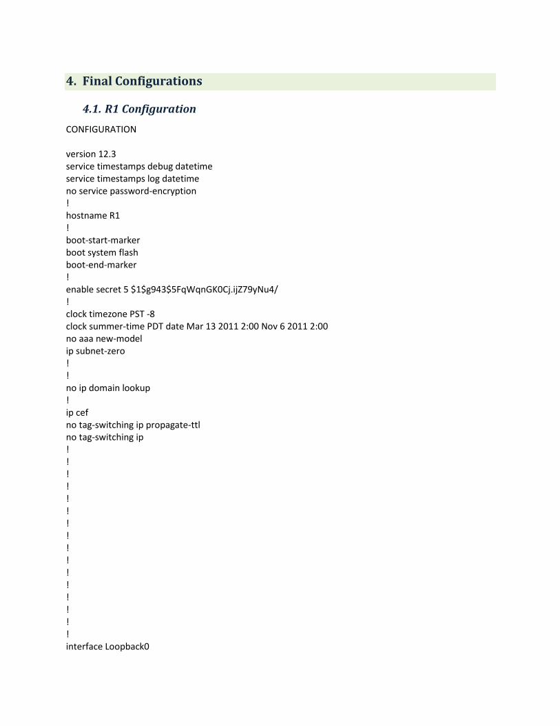
4. Final Configurations
4.1. R1 Configuration
CONFIGURATION
version 12.3
service timestamps debug datetime
service timestamps log datetime
no service password-encryption
!
hostname R1
!
boot-start-marker
boot system flash
boot-end-marker
!
enable secret 5 $1$g943$5FqWqnGK0Cj.ijZ79yNu4/
!
clock timezone PST -8
clock summer-time PDT date Mar 13 2011 2:00 Nov 6 2011 2:00
no aaa new-model
ip subnet-zero
!
!
no ip domain lookup
!
ip cef
no tag-switching ip propagate-ttl
no tag-switching ip
!
!
!
!
!
!
!
!
!
!
!
!
!
!
!
!
interface Loopback0

ip address 10.1.1.1 255.255.255.255
ip nat inside
!
interface Tunnel12
ip address 172.16.12.1 255.255.255.240
ip access-group 102 out
ip nat inside
tunnel source 10.99.99.1
tunnel destination 10.99.99.2
!
interface Tunnel13
ip address 172.16.13.1 255.255.255.240
ip access-group 102 out
ip nat inside
tunnel source 10.99.99.1
tunnel destination 10.99.99.3
!
interface FastEthernet0/0
no ip address
duplex auto
speed auto
!
interface FastEthernet0/0.1
encapsulation isl 1
ip address 192.168.1.1 255.255.255.248
no ip redirects
ip nat inside
no snmp trap link-status
!
interface FastEthernet0/0.11
encapsulation isl 11
ip address 192.168.11.1 255.255.255.192
no ip redirects
ip nat inside
no snmp trap link-status
!
interface FastEthernet0/0.99
encapsulation isl 99
ip address 10.99.99.1 255.255.255.248
ip access-group 101 in
ip access-group 102 out
no ip redirects
ip nat outside
no snmp trap link-status
!
interface Serial0/0
no ip address
encapsulation frame-relay

!
router eigrp 1003
redistribute rip metric 1544 10 128 128 1500
network 172.16.12.0 0.0.0.15
network 172.16.13.0 0.0.0.15
no auto-summary
!
router rip
passive-interface FastEthernet0/0.99
network 10.0.0.0
network 192.168.1.0
network 192.168.11.0
!
ip nat inside source list 1 interface FastEthernet0/0.99 overload
ip http server
ip http port 8080
ip classless
ip route 0.0.0.0 0.0.0.0 10.99.99.4
!
!
no logging trap
access-list 1 permit 10.1.1.1
access-list 1 permit 192.168.1.0 0.0.0.7
access-list 1 permit 192.168.11.0 0.0.0.63
access-list 1 permit 172.16.12.0 0.0.0.15
access-list 1 permit 172.16.13.0 0.0.0.15
access-list 1 deny any
access-list 101 deny tcp any any eq telnet
access-list 101 permit tcp any any eq 22
access-list 101 permit ip 192.168.1.0 0.0.0.7 192.168.1.0 0.0.0.7
access-list 101 permit ip 192.168.11.0 0.0.0.7 192.168.1.0 0.0.0.63
access-list 101 permit ip host 10.1.1.1 192.168.1.0 0.0.0.7
access-list 101 permit ip 172.16.12.0 0.0.0.7 192.168.1.0 0.0.0.7
access-list 101 permit ip 172.16.13.0 0.0.0.7 192.168.1.0 0.0.0.7
access-list 101 permit ip host 10.4.4.4 192.168.1.0 0.0.0.7
access-list 101 deny ip any 192.168.1.0 0.0.0.7
access-list 101 permit ip any any
access-list 102 deny tcp any any eq smtp
access-list 102 permit ip any any
!
!
!
!
dial-peer cor custom
!
!
!
banner motd ^CWelcome to the CCNA VPN Lab!^C

!
line con 0
privilege level 15
password Cisco123
line aux 0
password Cisco123
login
modem InOut
transport input all
flowcontrol hardware
line vty 0 4
password Cisco123
login
line vty 5 181
password Cisco123
login
!
ntp clock-period 17180476
ntp server 10.99.99.4
!
end
IP ROUTING TABLE
R1#sh ip route
Codes: C - connected, S - static, R - RIP, M - mobile, B - BGP
D - EIGRP, EX - EIGRP external, O - OSPF, IA - OSPF inter area
N1 - OSPF NSSA external type 1, N2 - OSPF NSSA external type 2
E1 - OSPF external type 1, E2 - OSPF external type 2
i - IS-IS, su - IS-IS summary, L1 - IS-IS level-1, L2 - IS-IS level-2
ia - IS-IS inter area, * - candidate default, U - per-user static route
o - ODR, P - periodic downloaded static route
Gateway of last resort is 10.99.99.4 to network 0.0.0.0
172.16.0.0/28 is subnetted, 3 subnets
D 172.16.23.0 [90/310044416] via 172.16.12.2, 2d20h, Tunnel12
[90/310044416] via 172.16.13.3, 2d20h, Tunnel13
C 172.16.12.0 is directly connected, Tunnel12
C 172.16.13.0 is directly connected, Tunnel13
192.168.11.0/26 is subnetted, 1 subnets
C 192.168.11.0 is directly connected, FastEthernet0/0.11
10.0.0.0/8 is variably subnetted, 4 subnets, 2 masks
D 10.2.2.2/32 [90/297372416] via 172.16.12.2, 2d20h, Tunnel12
D EX 10.3.3.3/32 [170/297372416] via 172.16.13.3, 1d18h, Tunnel13
C 10.99.99.0/29 is directly connected, FastEthernet0/0.99
C 10.1.1.1/32 is directly connected, Loopback0

192.168.22.0/26 is subnetted, 1 subnets
D 192.168.22.0 [90/297246976] via 172.16.12.2, 2d20h, Tunnel12
192.168.1.0/29 is subnetted, 1 subnets
C 192.168.1.0 is directly connected, FastEthernet0/0.1
192.168.2.0/29 is subnetted, 1 subnets
D 192.168.2.0 [90/297246976] via 172.16.12.2, 2d20h, Tunnel12
192.168.3.0/29 is subnetted, 1 subnets
D EX 192.168.3.0 [170/297246976] via 172.16.13.3, 1d18h, Tunnel13
192.168.33.0/26 is subnetted, 1 subnets
D EX 192.168.33.0 [170/297246976] via 172.16.13.3, 1d18h, Tunnel13
S* 0.0.0.0/0 [1/0] via 10.99.99.4
EIGRP
R1#sh ip eigrp neighbors
IP-EIGRP neighbors for process 1003
H Address Interface Hold Uptime SRTT RTO Q Seq
(sec) (ms) Cnt Num
1 172.16.13.3 Tu13 13 2d20h 60 5000 0 21
0 172.16.12.2 Tu12 13 2d20h 117 5000 0 24
R1#sh ip eigrp inter
IP-EIGRP interfaces for process 1003
Xmit Queue Mean Pacing Time Multicast Pending
Interface Peers Un/Reliable SRTT Un/Reliable Flow Timer Routes
Tu12 1 0/0 117 71/2702 3238 0
Tu13 1 0/0 60 71/2702 3006 0
R1#sh ip eigrp topology
IP-EIGRP Topology Table for AS(1003)/ID(10.1.1.1)
Codes: P - Passive, A - Active, U - Update, Q - Query, R - Reply,
r - reply Status, s - sia Status
P 10.2.2.2/32, 1 successors, FD is 297372416
via 172.16.12.2 (297372416/128256), Tunnel12
P 10.3.3.3/32, 1 successors, FD is 297246976
via 172.16.13.3 (297372416/128256), Tunnel13
P 10.99.99.0/29, 1 successors, FD is 1660416
via Redistributed (1660416/0)
via 172.16.13.3 (297246976/28160), Tunnel13
P 10.1.1.1/32, 1 successors, FD is 1660416
via Redistributed (1660416/0)
P 192.168.33.0/26, 1 successors, FD is 297246976
via 172.16.13.3 (297246976/28160), Tunnel13
P 192.168.11.0/26, 1 successors, FD is 1660416
via Redistributed (1660416/0)

P 192.168.1.0/29, 1 successors, FD is 1660416
via Redistributed (1660416/0)
P 192.168.2.0/29, 1 successors, FD is 297246976
via 172.16.12.2 (297246976/28160), Tunnel12
P 192.168.3.0/29, 1 successors, FD is 297246976
Codes: P - Passive, A - Active, U - Update, Q - Query, R - Reply,
r - reply Status, s - sia Status
via 172.16.13.3 (297246976/28160), Tunnel13
P 192.168.22.0/26, 1 successors, FD is 297246976
via 172.16.12.2 (297246976/28160), Tunnel12
P 172.16.23.0/28, 2 successors, FD is 310044416
via 172.16.13.3 (310044416/297244416), Tunnel13
via 172.16.12.2 (310044416/297244416), Tunnel12
P 172.16.12.0/28, 1 successors, FD is 297244416
via Connected, Tunnel12
P 172.16.13.0/28, 1 successors, FD is 297244416
via Connected, Tunnel13
R1#sh ip protocols
Routing Protocol is "eigrp 1003"
Outgoing update filter list for all interfaces is not set
Incoming update filter list for all interfaces is not set
Default networks flagged in outgoing updates
Default networks accepted from incoming updates
EIGRP metric weight K1=1, K2=0, K3=1, K4=0, K5=0
EIGRP maximum hopcount 100
EIGRP maximum metric variance 1
Redistributing: eigrp 1003, rip
EIGRP NSF-aware route hold timer is 240s
Automatic network summarization is not in effect
Maximum path: 4
Routing for Networks:
172.16.12.0/28
172.16.13.0/28
Routing Information Sources:
Gateway Distance Last Update
172.16.13.3 90 1d08h
172.16.12.2 90 1d08h
Distance: internal 90 external 170
Routing Protocol is "rip"
Sending updates every 30 seconds, next due in 25 seconds
Invalid after 180 seconds, hold down 180, flushed after 240
Outgoing update filter list for all interfaces is not set
Incoming update filter list for all interfaces is not set
Redistributing: rip

Default version control: send version 1, receive any version
Interface Send Recv Triggered RIP Key-chain
FastEthernet0/0.1 1 1 2
FastEthernet0/0.11 1 1 2
Loopback0 1 1 2
Automatic network summarization is in effect
Maximum path: 4
Routing for Networks:
10.0.0.0
192.168.1.0
192.168.11.0
Passive Interface(s):
FastEthernet0/0.99
Routing Information Sources:
Gateway Distance Last Update
Distance: (default is 120)
4.2. R2 Configuration
CONFIGURATION
version 12.3
service timestamps debug datetime msec
service timestamps log datetime
no service password-encryption
!
hostname R2
!
boot-start-marker
boot-end-marker
!
enable secret 5 $1$8STC$Sjhm3NtDASbFhCnGnTD2g.
!
clock timezone PST -8
clock summer-time PDT date Mar 13 2011 2:00 Nov 6 2011 2:00
no aaa new-model
ip subnet-zero
!
!
no ip domain lookup
!
ip cef
no tag-switching ip
!
!
!
!

!
!
!
!
!
!
!
!
!
!
!
interface Loopback0
ip address 10.2.2.2 255.255.255.255
ip nat inside
!
interface Tunnel12
ip address 172.16.12.2 255.255.255.240
ip access-group 102 out
ip nat inside
tunnel source 10.99.99.2
tunnel destination 10.99.99.1
!
interface Tunnel23
ip address 172.16.23.2 255.255.255.240
ip access-group 102 out
ip nat inside
tunnel source 10.99.99.2
tunnel destination 10.99.99.3
!
interface FastEthernet0/0
no ip address
duplex auto
speed auto
!
interface FastEthernet0/0.2
encapsulation isl 2
ip address 192.168.2.2 255.255.255.248
no ip redirects
ip nat inside
no snmp trap link-status
!
interface FastEthernet0/0.22
encapsulation isl 11
ip address 192.168.22.2 255.255.255.192
no ip redirects
ip nat inside
no snmp trap link-status
!

interface FastEthernet0/0.99
encapsulation isl 99
ip address 10.99.99.2 255.255.255.248
ip access-group 101 in
ip access-group 102 out
no ip redirects
ip nat outside
no snmp trap link-status
!
interface Serial0/0
no ip address
encapsulation frame-relay
!
router eigrp 1003
network 10.2.2.2 0.0.0.0
network 172.16.12.0 0.0.0.15
network 172.16.23.0 0.0.0.15
network 192.168.2.0 0.0.0.7
network 192.168.22.0 0.0.0.31
no auto-summary
!
ip nat inside source list 1 interface FastEthernet0/0.99 overload
ip nat inside source static tcp 192.168.22.1 25 interface FastEthernet0/0.99 25
ip http server
ip http port 8080
ip classless
ip route 0.0.0.0 0.0.0.0 10.99.99.4
!
!
access-list 1 permit 10.2.2.2
access-list 1 permit 192.168.2.0 0.0.0.7
access-list 1 permit 192.168.22.0 0.0.0.63
access-list 1 permit 172.16.12.0 0.0.0.15
access-list 1 permit 172.16.23.0 0.0.0.15
access-list 1 deny any
access-list 101 permit ip 192.168.2.0 0.0.0.7 192.168.1.0 0.0.0.7
access-list 101 permit ip 192.168.22.0 0.0.0.7 192.168.1.0 0.0.0.63
access-list 101 permit ip host 10.2.2.2 192.168.1.0 0.0.0.7
access-list 101 permit ip 172.16.12.0 0.0.0.7 192.168.1.0 0.0.0.7
access-list 101 permit ip 172.16.23.0 0.0.0.7 192.168.1.0 0.0.0.7
access-list 101 permit ip host 10.4.4.4 192.168.1.0 0.0.0.7
access-list 101 deny ip any 192.168.2.0 0.0.0.7
access-list 101 permit ip any any
access-list 102 deny udp any any eq tftp
access-list 102 deny tcp any any eq smtp
access-list 102 permit ip any any
!
!
!
!
!
banner motd ^CWelcome to the CCNA VPN Lab!^C
!
line con 0
privilege level 15
password Cisco123
line aux 0
password Cisco123
login
line vty 0 4
password Cisco123
login
line vty 5 181
password Cisco123
login
!
ntp clock-period 17180762
ntp server 10.99.99.4
!
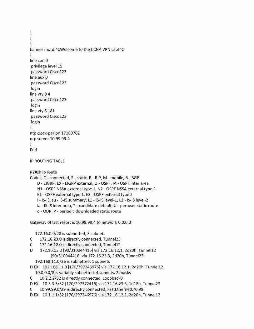
End
IP ROUTING TABLE
R2#sh ip route
Codes: C - connected, S - static, R - RIP, M - mobile, B - BGP
D - EIGRP, EX - EIGRP external, O - OSPF, IA - OSPF inter area
N1 - OSPF NSSA external type 1, N2 - OSPF NSSA external type 2
E1 - OSPF external type 1, E2 - OSPF external type 2
i - IS-IS, su - IS-IS summary, L1 - IS-IS level-1, L2 - IS-IS level-2
ia - IS-IS inter area, * - candidate default, U - per-user static route
o - ODR, P - periodic downloaded static route
Gateway of last resort is 10.99.99.4 to network 0.0.0.0
172.16.0.0/28 is subnetted, 3 subnets
C 172.16.23.0 is directly connected, Tunnel23
C 172.16.12.0 is directly connected, Tunnel12
D 172.16.13.0 [90/310044416] via 172.16.12.1, 2d20h, Tunnel12
[90/310044416] via 172.16.23.3, 2d20h, Tunnel23
192.168.11.0/26 is subnetted, 1 subnets
D EX 192.168.11.0 [170/297246976] via 172.16.12.1, 2d20h, Tunnel12
10.0.0.0/8 is variably subnetted, 4 subnets, 2 masks
C 10.2.2.2/32 is directly connected, Loopback0
D EX 10.3.3.3/32 [170/297372416] via 172.16.23.3, 1d18h, Tunnel23
C 10.99.99.0/29 is directly connected, FastEthernet0/0.99
D EX 10.1.1.1/32 [170/297246976] via 172.16.12.1, 2d20h, Tunnel12

192.168.22.0/26 is subnetted, 1 subnets
C 192.168.22.0 is directly connected, FastEthernet0/0.22
192.168.1.0/29 is subnetted, 1 subnets
D EX 192.168.1.0 [170/297246976] via 172.16.12.1, 2d20h, Tunnel12
192.168.2.0/29 is subnetted, 1 subnets
C 192.168.2.0 is directly connected, FastEthernet0/0.2
192.168.3.0/29 is subnetted, 1 subnets
D EX 192.168.3.0 [170/297246976] via 172.16.23.3, 1d18h, Tunnel23
192.168.33.0/26 is subnetted, 1 subnets
D EX 192.168.33.0 [170/297246976] via 172.16.23.3, 1d18h, Tunnel23
S* 0.0.0.0/0 [1/0] via 10.99.99.4
EIGRP
R2#sh ip eigrp neighbors
IP-EIGRP neighbors for process 1003
H Address Interface Hold Uptime SRTT RTO Q Seq
(sec) (ms) Cnt Num
1 172.16.23.3 Tu23 12 2d20h 528 5000 0 20
0 172.16.12.1 Tu12 12 2d20h 138 5000 0 29
R2#sh ip eigrp interfaces
IP-EIGRP interfaces for process 1003
Xmit Queue Mean Pacing Time Multicast Pending
Interface Peers Un/Reliable SRTT Un/Reliable Flow Timer Routes
Tu12 1 0/0 138 71/2702 3474 0
Tu23 1 0/0 528 71/2702 5338 0
Lo0 0 0/0 0 0/10 0 0
Fa0/0.2 0 0/0 0 0/10 0 0
Fa0/0.22 0 0/0 0 0/10 0 0
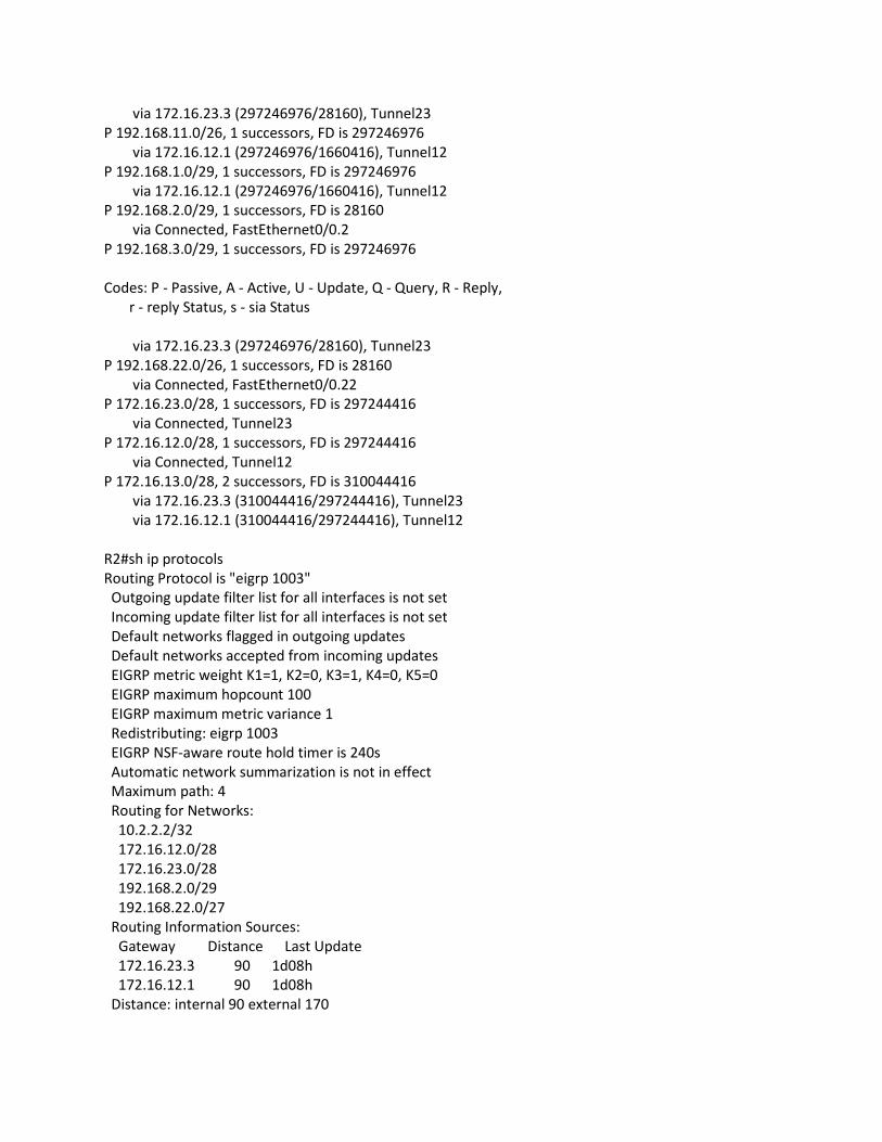
R2#sh ip eigrp topology
IP-EIGRP Topology Table for AS(1003)/ID(10.2.2.2)
Codes: P - Passive, A - Active, U - Update, Q - Query, R - Reply,
r - reply Status, s - sia Status
P 10.2.2.2/32, 1 successors, FD is 128256
via Connected, Loopback0
P 10.3.3.3/32, 1 successors, FD is 297246976
via 172.16.23.3 (297372416/128256), Tunnel23
P 10.99.99.0/29, 0 successors, FD is Inaccessible
via 172.16.23.3 (297246976/28160), Tunnel23
via 172.16.12.1 (297246976/1660416), Tunnel12
P 10.1.1.1/32, 1 successors, FD is 297246976
via 172.16.12.1 (297246976/1660416), Tunnel12
P 192.168.33.0/26, 1 successors, FD is 297246976
via 172.16.23.3 (297246976/28160), Tunnel23
P 192.168.11.0/26, 1 successors, FD is 297246976
via 172.16.12.1 (297246976/1660416), Tunnel12
P 192.168.1.0/29, 1 successors, FD is 297246976
via 172.16.12.1 (297246976/1660416), Tunnel12
P 192.168.2.0/29, 1 successors, FD is 28160
via Connected, FastEthernet0/0.2
P 192.168.3.0/29, 1 successors, FD is 297246976
Codes: P - Passive, A - Active, U - Update, Q - Query, R - Reply,
r - reply Status, s - sia Status
via 172.16.23.3 (297246976/28160), Tunnel23
P 192.168.22.0/26, 1 successors, FD is 28160
via Connected, FastEthernet0/0.22
P 172.16.23.0/28, 1 successors, FD is 297244416
via Connected, Tunnel23
P 172.16.12.0/28, 1 successors, FD is 297244416
via Connected, Tunnel12
P 172.16.13.0/28, 2 successors, FD is 310044416
via 172.16.23.3 (310044416/297244416), Tunnel23
via 172.16.12.1 (310044416/297244416), Tunnel12
R2#sh ip protocols
Routing Protocol is "eigrp 1003"
Outgoing update filter list for all interfaces is not set
Incoming update filter list for all interfaces is not set
Default networks flagged in outgoing updates
Default networks accepted from incoming updates
EIGRP metric weight K1=1, K2=0, K3=1, K4=0, K5=0
EIGRP maximum hopcount 100
EIGRP maximum metric variance 1
Redistributing: eigrp 1003
EIGRP NSF-aware route hold timer is 240s
Automatic network summarization is not in effect
Maximum path: 4
Routing for Networks:
10.2.2.2/32
172.16.12.0/28
172.16.23.0/28
192.168.2.0/29
192.168.22.0/27
Routing Information Sources:
Gateway Distance Last Update
172.16.23.3 90 1d08h
172.16.12.1 90 1d08h
Distance: internal 90 external 170

4.3. R3 Configuration
CONFIGURATION
version 12.3
service timestamps debug datetime
service timestamps log datetime
no service password-encryption
!
hostname R3
!
boot-start-marker
boot-end-marker
!
enable secret 5 $1$9NeA$Dhpt4GUrrwTwcVYAJTOSo0
!
clock timezone PST -8
clock summer-time PDT date Mar 13 2011 2:00 Nov 6 2011 2:00
no aaa new-model
ip subnet-zero
!
!
no ip domain lookup
!
ip cef
clns routing
no tag-switching ip
!
!
!
!
!
!
!
!
!
!
!
!
!
!
!
!
interface Loopback0
ip address 10.3.3.3 255.255.255.255
ip nat inside
!

interface Tunnel13
ip address 172.16.13.3 255.255.255.240
ip access-group 102 out
ip nat inside
tunnel source 10.99.99.3
tunnel destination 10.99.99.1
!
interface Tunnel23
ip address 172.16.23.3 255.255.255.240
ip access-group 102 out
ip nat inside
tunnel source 10.99.99.3
tunnel destination 10.99.99.2
!
interface FastEthernet0/0
no ip address
duplex auto
speed auto
!
interface FastEthernet0/0.3
encapsulation isl 3
ip address 192.168.3.3 255.255.255.248
no ip redirects
ip nat inside
no snmp trap link-status
!
interface FastEthernet0/0.33
encapsulation isl 33
ip address 192.168.33.3 255.255.255.192
no ip redirects
ip nat inside
no snmp trap link-status
!
interface FastEthernet0/0.99
encapsulation isl 99
ip address 10.99.99.3 255.255.255.248
ip access-group 101 in
ip access-group 102 out
no ip redirects
ip nat outside
no snmp trap link-status
!
interface Serial0/0
no ip address
encapsulation frame-relay
!
router eigrp 1003
redistribute connected
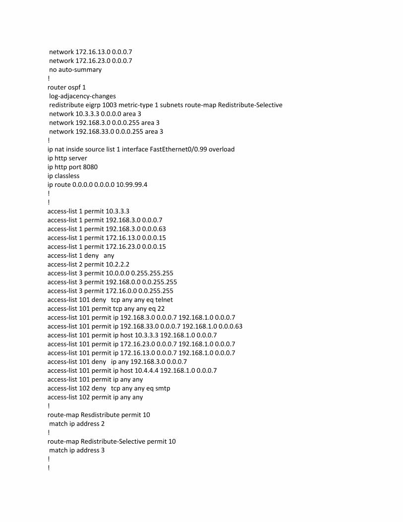
network 172.16.13.0 0.0.0.7
network 172.16.23.0 0.0.0.7
no auto-summary
!
router ospf 1
log-adjacency-changes
redistribute eigrp 1003 metric-type 1 subnets route-map Redistribute-Selective
network 10.3.3.3 0.0.0.0 area 3
network 192.168.3.0 0.0.0.255 area 3
network 192.168.33.0 0.0.0.255 area 3
!
ip nat inside source list 1 interface FastEthernet0/0.99 overload
ip http server
ip http port 8080
ip classless
ip route 0.0.0.0 0.0.0.0 10.99.99.4
!
!
access-list 1 permit 10.3.3.3
access-list 1 permit 192.168.3.0 0.0.0.7
access-list 1 permit 192.168.3.0 0.0.0.63
access-list 1 permit 172.16.13.0 0.0.0.15
access-list 1 permit 172.16.23.0 0.0.0.15
access-list 1 deny any
access-list 2 permit 10.2.2.2
access-list 3 permit 10.0.0.0 0.255.255.255
access-list 3 permit 192.168.0.0 0.0.255.255
access-list 3 permit 172.16.0.0 0.0.255.255
access-list 101 deny tcp any any eq telnet
access-list 101 permit tcp any any eq 22
access-list 101 permit ip 192.168.3.0 0.0.0.7 192.168.1.0 0.0.0.7
access-list 101 permit ip 192.168.33.0 0.0.0.7 192.168.1.0 0.0.0.63
access-list 101 permit ip host 10.3.3.3 192.168.1.0 0.0.0.7
access-list 101 permit ip 172.16.23.0 0.0.0.7 192.168.1.0 0.0.0.7
access-list 101 permit ip 172.16.13.0 0.0.0.7 192.168.1.0 0.0.0.7
access-list 101 deny ip any 192.168.3.0 0.0.0.7
access-list 101 permit ip host 10.4.4.4 192.168.1.0 0.0.0.7
access-list 101 permit ip any any
access-list 102 deny tcp any any eq smtp
access-list 102 permit ip any any
!
route-map Resdistribute permit 10
match ip address 2
!
route-map Redistribute-Selective permit 10
match ip address 3
!
!

!
!
!
banner motd ^CWelcome to the CCNA VPN Lab!^C
!
line con 0
privilege level 15
password Cisco123
line aux 0
password Cisco123
login
line vty 0 4
password Cisco123
login
line vty 5 181
password Cisco123
login
!
ntp clock-period 17180555
ntp server 10.99.99.4
!
end
IP ROUTING TABLE
R3#sh ip route
Codes: C - connected, S - static, R - RIP, M - mobile, B - BGP
D - EIGRP, EX - EIGRP external, O - OSPF, IA - OSPF inter area
N1 - OSPF NSSA external type 1, N2 - OSPF NSSA external type 2
E1 - OSPF external type 1, E2 - OSPF external type 2
i - IS-IS, su - IS-IS summary, L1 - IS-IS level-1, L2 - IS-IS level-2
ia - IS-IS inter area, * - candidate default, U - per-user static route
o - ODR, P - periodic downloaded static route
Gateway of last resort is 10.99.99.4 to network 0.0.0.0
172.16.0.0/28 is subnetted, 3 subnets
C 172.16.23.0 is directly connected, Tunnel23
D 172.16.12.0 [90/310044416] via 172.16.13.1, 2d20h, Tunnel13
[90/310044416] via 172.16.23.2, 2d20h, Tunnel23
C 172.16.13.0 is directly connected, Tunnel13
192.168.11.0/26 is subnetted, 1 subnets
D EX 192.168.11.0 [170/297246976] via 172.16.13.1, 2d20h, Tunnel13
10.0.0.0/8 is variably subnetted, 5 subnets, 2 masks
D 10.2.2.2/32 [90/297372416] via 172.16.23.2, 2d20h, Tunnel23
C 10.3.3.3/32 is directly connected, Loopback0
C 10.99.99.0/29 is directly connected, FastEthernet0/0.99
D EX 10.1.1.1/32 [170/297246976] via 172.16.13.1, 2d20h, Tunnel13

O 10.4.4.4/32 [110/2] via 192.168.33.4, 1d08h, FastEthernet0/0.33
192.168.22.0/26 is subnetted, 1 subnets
D 192.168.22.0 [90/297246976] via 172.16.23.2, 2d20h, Tunnel23
192.168.1.0/29 is subnetted, 1 subnets
D EX 192.168.1.0 [170/297246976] via 172.16.13.1, 2d20h, Tunnel13
192.168.2.0/29 is subnetted, 1 subnets
D 192.168.2.0 [90/297246976] via 172.16.23.2, 2d20h, Tunnel23
192.168.3.0/29 is subnetted, 1 subnets
C 192.168.3.0 is directly connected, FastEthernet0/0.3
192.168.33.0/26 is subnetted, 1 subnets
C 192.168.33.0 is directly connected, FastEthernet0/0.33
S* 0.0.0.0/0 [1/0] via 10.99.99.4
OSPF
R3#sh ip ospf neighbor
Neighbor ID Pri State Dead Time Address Interface
10.4.4.4 1 FULL/DR 00:00:39 192.168.33.4 FastEthernet0/0.33
R3#sh ip ospf interface
FastEthernet0/0.33 is up, line protocol is up
Internet Address 192.168.33.3/26, Area 3
Process ID 1, Router ID 10.3.3.3, Network Type BROADCAST, Cost: 1
Transmit Delay is 1 sec, State BDR, Priority 1
Designated Router (ID) 10.4.4.4, Interface address 192.168.33.4
Backup Designated router (ID) 10.3.3.3, Interface address 192.168.33.3
Timer intervals configured, Hello 10, Dead 40, Wait 40, Retransmit 5
oob-resync timeout 40
Hello due in 00:00:03
Index 2/2, flood queue length 0
Next 0x0(0)/0x0(0)
Last flood scan length is 9, maximum is 9
Last flood scan time is 0 msec, maximum is 4 msec
Neighbor Count is 1, Adjacent neighbor count is 1
Adjacent with neighbor 10.4.4.4 (Designated Router)
Suppress hello for 0 neighbor(s)
Loopback0 is up, line protocol is up
Internet Address 10.3.3.3/32, Area 3
Process ID 1, Router ID 10.3.3.3, Network Type LOOPBACK, Cost: 1
Loopback interface is treated as a stub Host
FastEthernet0/0.3 is up, line protocol is up
Internet Address 192.168.3.3/29, Area 3
Process ID 1, Router ID 10.3.3.3, Network Type BROADCAST, Cost: 1
Transmit Delay is 1 sec, State DR, Priority 1
Designated Router (ID) 10.3.3.3, Interface address 192.168.3.3
No backup designated router on this network
Timer intervals configured, Hello 10, Dead 40, Wait 40, Retransmit 5

oob-resync timeout 40
Hello due in 00:00:09
Index 1/1, flood queue length 0
Next 0x0(0)/0x0(0)
Last flood scan length is 0, maximum is 0
Last flood scan time is 0 msec, maximum is 0 msec
Neighbor Count is 0, Adjacent neighbor count is 0
Suppress hello for 0 neighbor(s)
R3#sh ip ospf database
OSPF Router with ID (10.3.3.3) (Process ID 1)
Router Link States (Area 3)
Link ID ADV Router Age Seq# Checksum Link count
10.3.3.3 10.3.3.3 91 0x80000080 0x00E5EE 3
10.4.4.4 10.4.4.4 1214 0x8000007D 0x00C283 2
Net Link States (Area 3)
Link ID ADV Router Age Seq# Checksum
192.168.33.4 10.4.4.4 1214 0x8000007B 0x00D060
Type-5 AS External Link States
Link ID ADV Router Age Seq# Checksum Tag
10.1.1.1 10.3.3.3 91 0x8000003B 0x00B214 0
10.2.2.2 10.3.3.3 91 0x8000003B 0x009132 0
172.16.12.0 10.3.3.3 91 0x8000003B 0x00F128 0
172.16.13.0 10.3.3.3 91 0x8000003B 0x00E632 0
172.16.23.0 10.3.3.3 91 0x8000003B 0x007896 0
192.168.1.0 10.3.3.3 91 0x8000003B 0x006F01 0
192.168.2.0 10.3.3.3 91 0x8000003B 0x00640B 0
192.168.11.0 10.3.3.3 93 0x8000003B 0x00AFEE 0
192.168.22.0 10.3.3.3 93 0x8000003B 0x00365D 0
EIGRP
IP-EIGRP neighbors for process 1003
H Address Interface Hold Uptime SRTT RTO Q Seq
(sec) (ms) Cnt Num
1 172.16.23.2 Tu23 14 2d20h 45 5000 0 25
0 172.16.13.1 Tu13 12 2d20h 67 5000 0 30
R3# sh ip eigrp interfaces
IP-EIGRP interfaces for process 1003

Xmit Queue Mean Pacing Time Multicast Pending
Interface Peers Un/Reliable SRTT Un/Reliable Flow Timer Routes
Tu13 1 0/0 67 71/2702 3038 0
Tu23 1 0/0 45 71/2702 2926 0
R3# sh ip eigrp topology
IP-EIGRP Topology Table for AS(1003)/ID(10.3.3.3)
Codes: P - Passive, A - Active, U - Update, Q - Query, R - Reply,
r - reply Status, s - sia Status
P 10.2.2.2/32, 1 successors, FD is 297372416
via 172.16.23.2 (297372416/128256), Tunnel23
P 10.3.3.3/32, 1 successors, FD is 128256
via Rconnected (128256/0)
P 10.99.99.0/29, 1 successors, FD is 28160
via Rconnected (28160/0)
P 10.1.1.1/32, 1 successors, FD is 297246976
via 172.16.13.1 (297246976/1660416), Tunnel13
P 192.168.33.0/26, 1 successors, FD is 28160
via Rconnected (28160/0)
P 192.168.11.0/26, 1 successors, FD is 297246976
via 172.16.13.1 (297246976/1660416), Tunnel13
P 192.168.1.0/29, 1 successors, FD is 297246976
via 172.16.13.1 (297246976/1660416), Tunnel13
P 192.168.2.0/29, 1 successors, FD is 297246976
via 172.16.23.2 (297246976/28160), Tunnel23
P 192.168.3.0/29, 1 successors, FD is 28160
via Rconnected (28160/0)
Codes: P - Passive, A - Active, U - Update, Q - Query, R - Reply,
r - reply Status, s - sia Status
P 192.168.22.0/26, 1 successors, FD is 297246976
via 172.16.23.2 (297246976/28160), Tunnel23
P 172.16.23.0/28, 1 successors, FD is 297244416
via Connected, Tunnel23
P 172.16.12.0/28, 2 successors, FD is 310044416
via 172.16.23.2 (310044416/297244416), Tunnel23
via 172.16.13.1 (310044416/297244416), Tunnel13
P 172.16.13.0/28, 1 successors, FD is 297244416
via Connected, Tunnel13
R3#sh ip protocols
Routing Protocol is "ospf 1"
Outgoing update filter list for all interfaces is not set
Incoming update filter list for all interfaces is not set
Router ID 10.3.3.3

It is an autonomous system boundary router
Redistributing External Routes from,
eigrp 1003, includes subnets in redistribution
Number of areas in this router is 1. 1 normal 0 stub 0 nssa
Maximum path: 4
Routing for Networks:
10.3.3.3 0.0.0.0 area 3
192.168.3.0 0.0.0.255 area 3
192.168.33.0 0.0.0.255 area 3
Routing Information Sources:
Gateway Distance Last Update
10.4.4.4 110 1d08h
Distance: (default is 110)
Routing Protocol is "eigrp 1003"
Outgoing update filter list for all interfaces is not set
Incoming update filter list for all interfaces is not set
Default networks flagged in outgoing updates
Default networks accepted from incoming updates
EIGRP metric weight K1=1, K2=0, K3=1, K4=0, K5=0
EIGRP maximum hopcount 100
EIGRP maximum metric variance 1
Redistributing: connected, eigrp 1003
EIGRP NSF-aware route hold timer is 240s
Automatic network summarization is not in effect
Maximum path: 4
Routing for Networks:
172.16.13.0/29
172.16.23.0/29
Routing Information Sources:
Gateway Distance Last Update
172.16.23.2 90 2d20h
172.16.13.1 90 1d19h
Distance: internal 90 external 170
4.4. R4 Configuration
CONFIGURATION
version 15.0
service timestamps debug datetime msec
service timestamps log datetime msec
no service password-encryption
!
hostname R4
!
boot-start-marker

boot system flash:c2800nm-adventerprisek9-mz.150-1.M.bin
boot system flash usb1:c2800nm-adventerprisek9-mz.150-1.M.bin
boot-end-marker
!
card type e1 0 0
enable secret 5 $1$Woft$KnObg3Q90YQtwfhBw7SKy.
!
no aaa new-model
!
!
!
clock timezone PST -8
clock summer-time PDT date Mar 13 2011 2:00 Nov 6 2011 2:00
network-clock-participate wic 0
network-clock-participate wic 1
!
dot11 syslog
ip source-route
!
!
ip cef
!
!
ip name-server 216.136.95.2
ip name-server 64.132.94.250
no ipv6 cef
!
multilink bundle-name authenticated
!
!
!
!
mpls label protocol ldp
isdn switch-type primary-net5
!
!
!
!
!
!
voice-card 0
!
!
crypto pki trustpoint TP-self-signed-1522412998
enrollment selfsigned
subject-name cn=IOS-Self-Signed-Certificate-1522412998
revocation-check none
rsakeypair TP-self-signed-1522412998

!
!
crypto pki certificate chain TP-self-signed-1522412998
certificate self-signed 01
3082023A 308201A3 A0030201 02020101 300D0609 2A864886 F70D0101 04050030
31312F30 2D060355 04031326 494F532D 53656C66 2D536967 6E65642D 43657274
69666963 6174652D 31353232 34313239 3938301E 170D3131 30363130 30363132
34395A17 0D323030 31303130 30303030 305A3031 312F302D 06035504 03132649
4F532D53 656C662D 5369676E 65642D43 65727469 66696361 74652D31 35323234
31323939 3830819F 300D0609 2A864886 F70D0101 01050003 818D0030 81890281
8100B0F5 3EABC1CA FA9F74AC 90E9742B E4D11A6F 8B603D4D C68C1585 3C5FE549
108AA02D C82EB47E C348DC6C 94562B95 D78BB6FC A34BE8C5 7BBDCE59 09190858
C825FCE1 34B5F9D9 98902052 0E8D9744 4E3A99DA 6ED1C7B5 D6870F6F 056DEEBF
7A105B66 6825478C E1F4B47A A9200796 7AC17944 348D122B 8E4CD606 E1A6BFE2
AF270203 010001A3 62306030 0F060355 1D130101 FF040530 030101FF 300D0603
551D1104 06300482 02523430 1F060355 1D230418 30168014 A86C8927 FD2D1AD1
C20D36F3 52D6EAF3 211921AC 301D0603 551D0E04 160414A8 6C8927FD 2D1AD1C2
0D36F352 D6EAF321 1921AC30 0D06092A 864886F7 0D010104 05000381 81008779
243351FE 8494A8E6 F47E0C91 D9C99EF9 D361FA44 A20FB1B7 330ADCD0 5E03B6D1
434EEF27 8ED7DB17 0F2CA665 C21D7C75 FCFBE33A 09203CE9 A06B890B 6447E1F0
F1BECA81 72FCD388 3D81F548 9B93508C B08993D4 0A1F6850 C90B825D 906F0A37
7CED08DC 3A5B54DF 2F3F944B B95631BF E998A6BC 408C3FE7 D3B7EBE8 112C
quit
!
!
license udi pid CISCO2811 sn FTX1240A1NQ
username jjrinehart privilege 15 secret 5 $1$3Nq9$3R8euqE4Z7bMmU6xqSehl0
!
redundancy
!
!
controller E1 0/0/0
clock source internal
!
controller E1 0/0/1
!
controller E1 0/0/2
!
controller E1 0/0/3
!
controller E1 0/1/0
loopback local line
pri-group timeslots 1-31 service mgcp
!
!
!
!
!

!
!
!
!
interface Loopback0
ip address 10.4.4.4 255.255.255.255
!
!
interface FastEthernet0/0
no ip address
duplex half
speed auto
!
!
interface FastEthernet0/0.33
encapsulation dot1Q 33
ip address 192.168.33.4 255.255.255.192
!
interface FastEthernet0/0.99
encapsulation dot1Q 99
ip address 10.99.99.4 255.255.255.248
!
interface FastEthernet0/1
ip address 192.168.254.4 255.255.255.0
ip virtual-reassembly
duplex half
speed auto
!
!
interface Serial0/1/0:15
no ip address
encapsulation hdlc
isdn switch-type primary-net5
isdn incoming-voice voice
isdn bind-l3 ccm-manager
no cdp enable
!
!
!
router eigrp 100
network 10.99.99.0 0.0.0.255
network 192.168.254.0
!
router ospf 1
router-id 10.4.4.4
log-adjacency-changes
network 10.4.4.4 0.0.0.0 area 3
network 192.168.33.0 0.0.0.255 area 3

!
ip forward-protocol nd
ip http server
ip http authentication local
no ip http secure-server
ip http timeout-policy idle 60 life 86400 requests 10000
!
!
ip route 0.0.0.0 0.0.0.0 192.168.254.1
!
!
!
!
!
!
!
control-plane
!
!
!
voice-port 0/1/0:15
echo-cancel coverage 64
local-alerting
!
no ccm-manager fax protocol cisco
!
no mgcp package-capability res-package
no mgcp timer receive-rtcp
!
!
dial-peer voice 1 pots
!
!
!
banner motd ^CWelcome to the CCNA VPN Lab!^C
!
line con 0
privilege level 15
password cisco
line aux 0
password cisco
login
line vty 0 4
password cisco
login
transport input telnet ssh
line vty 5 988
password cisco

login
transport input telnet ssh
!
scheduler allocate 20000 1000
ntp server 128.249.1.1
end
IP ROUTING TABLE
R4#sh ip route
Codes: L - local, C - connected, S - static, R - RIP, M - mobile, B - BGP
D - EIGRP, EX - EIGRP external, O - OSPF, IA - OSPF inter area
N1 - OSPF NSSA external type 1, N2 - OSPF NSSA external type 2
E1 - OSPF external type 1, E2 - OSPF external type 2
i - IS-IS, su - IS-IS summary, L1 - IS-IS level-1, L2 - IS-IS level-2
ia - IS-IS inter area, * - candidate default, U - per-user static route
o - ODR, P - periodic downloaded static route, + - replicated route
Gateway of last resort is 192.168.254.1 to network 0.0.0.0
S* 0.0.0.0/0 [1/0] via 192.168.254.1
10.0.0.0/8 is variably subnetted, 6 subnets, 2 masks
O E1 10.1.1.1/32 [110/21] via 192.168.33.3, 1d08h, FastEthernet0/0.33
O E1 10.2.2.2/32 [110/21] via 192.168.33.3, 1d08h, FastEthernet0/0.33
O 10.3.3.3/32 [110/2] via 192.168.33.3, 2d20h, FastEthernet0/0.33
C 10.4.4.4/32 is directly connected, Loopback0
C 10.99.99.0/29 is directly connected, FastEthernet0/0.99
L 10.99.99.4/32 is directly connected, FastEthernet0/0.99
172.16.0.0/28 is subnetted, 3 subnets
O E1 172.16.12.0 [110/21] via 192.168.33.3, 1d08h, FastEthernet0/0.33
O E1 172.16.13.0 [110/21] via 192.168.33.3, 1d08h, FastEthernet0/0.33
O E1 172.16.23.0 [110/21] via 192.168.33.3, 1d08h, FastEthernet0/0.33
192.168.1.0/29 is subnetted, 1 subnets
O E1 192.168.1.0 [110/21] via 192.168.33.3, 1d08h, FastEthernet0/0.33
192.168.2.0/29 is subnetted, 1 subnets
O E1 192.168.2.0 [110/21] via 192.168.33.3, 1d08h, FastEthernet0/0.33
192.168.3.0/29 is subnetted, 1 subnets
O 192.168.3.0 [110/2] via 192.168.33.3, 2d20h, FastEthernet0/0.33
192.168.11.0/26 is subnetted, 1 subnets
O E1 192.168.11.0 [110/21] via 192.168.33.3, 1d08h, FastEthernet0/0.33
192.168.22.0/26 is subnetted, 1 subnets
O E1 192.168.22.0 [110/21] via 192.168.33.3, 1d08h, FastEthernet0/0.33
192.168.33.0/24 is variably subnetted, 2 subnets, 2 masks
C 192.168.33.0/26 is directly connected, FastEthernet0/0.33
L 192.168.33.4/32 is directly connected, FastEthernet0/0.33
192.168.254.0/24 is variably subnetted, 2 subnets, 2 masks
C 192.168.254.0/24 is directly connected, FastEthernet0/1
L 192.168.254.4/32 is directly connected, FastEthernet0/1

OSPF
R4#sh ip ospf neighbor
Neighbor ID Pri State Dead Time Address Interface
10.3.3.3 1 FULL/BDR 00:00:33 192.168.33.3 FastEthernet0/0.33
R4#sh ip ospf interface
Loopback0 is up, line protocol is up
Internet Address 10.4.4.4/32, Area 3
Process ID 1, Router ID 10.4.4.4, Network Type LOOPBACK, Cost: 1
Topology-MTID Cost Disabled Shutdown Topology Name
0 1 no no Base
Loopback interface is treated as a stub Host
FastEthernet0/0.33 is up, line protocol is up
Internet Address 192.168.33.4/26, Area 3
Process ID 1, Router ID 10.4.4.4, Network Type BROADCAST, Cost: 1
Topology-MTID Cost Disabled Shutdown Topology Name
0 1 no no Base
Transmit Delay is 1 sec, State DR, Priority 1
Designated Router (ID) 10.4.4.4, Interface address 192.168.33.4
Backup Designated router (ID) 10.3.3.3, Interface address 192.168.33.3
Timer intervals configured, Hello 10, Dead 40, Wait 40, Retransmit 5
oob-resync timeout 40
Hello due in 00:00:04
Supports Link-local Signaling (LLS)
Cisco NSF helper support enabled
IETF NSF helper support enabled
Index 2/2, flood queue length 0
Next 0x0(0)/0x0(0)
Last flood scan length is 0, maximum is 1
Last flood scan time is 0 msec, maximum is 4 msec
Neighbor Count is 1, Adjacent neighbor count is 1
Adjacent with neighbor 10.3.3.3 (Backup Designated Router)
Suppress hello for 0 neighbor(s)
R4#sh ip ospf database
OSPF Router with ID (10.4.4.4) (Process ID 1)
Router Link States (Area 3)
Link ID ADV Router Age Seq# Checksum Link count
10.3.3.3 10.3.3.3 380 0x80000080 0x00E5EE 3
10.4.4.4 10.4.4.4 1501 0x8000007D 0x00C283 2
Net Link States (Area 3)

Link ID ADV Router Age Seq# Checksum
192.168.33.4 10.4.4.4 1501 0x8000007B 0x00D060
Type-5 AS External Link States
Link ID ADV Router Age Seq# Checksum Tag
10.1.1.1 10.3.3.3 380 0x8000003B 0x00B214 0
10.2.2.2 10.3.3.3 380 0x8000003B 0x009132 0
172.16.12.0 10.3.3.3 380 0x8000003B 0x00F128 0
172.16.13.0 10.3.3.3 380 0x8000003B 0x00E632 0
172.16.23.0 10.3.3.3 380 0x8000003B 0x007896 0
192.168.1.0 10.3.3.3 380 0x8000003B 0x006F01 0
192.168.2.0 10.3.3.3 380 0x8000003B 0x00640B 0
192.168.11.0 10.3.3.3 382 0x8000003B 0x00AFEE 0
192.168.22.0 10.3.3.3 382 0x8000003B 0x00365D 0
R4#sh ip protocols
*** IP Routing is NSF aware ***
Routing Protocol is "eigrp 100"
Outgoing update filter list for all interfaces is not set
Incoming update filter list for all interfaces is not set
Default networks flagged in outgoing updates
Default networks accepted from incoming updates
Redistributing: eigrp 100
EIGRP-IPv4 Protocol for AS(100)
Metric weight K1=1, K2=0, K3=1, K4=0, K5=0
NSF-aware route hold timer is 240
Router-ID: 192.168.254.4
Topology : 0 (base)
Active Timer: 3 min
Distance: internal 90 external 170
Maximum path: 4
Maximum hopcount 100
Maximum metric variance 1
Automatic Summarization: disabled
Maximum path: 4
Routing for Networks:
10.99.99.0/24
192.168.254.0
Routing Information Sources:
Gateway Distance Last Update
192.168.254.1 90 1d19h
Distance: internal 90 external 170
Routing Protocol is "ospf 1"
Outgoing update filter list for all interfaces is not set

Incoming update filter list for all interfaces is not set
Router ID 10.4.4.4
Number of areas in this router is 1. 1 normal 0 stub 0 nssa
Maximum path: 4
Routing for Networks:
10.4.4.4 0.0.0.0 area 3
192.168.33.0 0.0.0.255 area 3
Routing Information Sources:
Gateway Distance Last Update
10.3.3.3 110 1d08h
Distance: (default is 110)
4.5. SW1 Configuration
CONFIGURATION
version 12.1
no service pad
service timestamps debug uptime
service timestamps log uptime
no service password-encryption
!
hostname SW1-3550
!
enable secret 5 $1$nrbE$yBDx0XOB2MkgzEQ8yxL88/
!
clock timezone PST -8
clock summer-time PDT date Mar 13 2011 2:00 Nov 6 2011 2:00
ip subnet-zero
ip routing
!
no ip domain-lookup
vtp domain null
vtp mode transparent
!
spanning-tree mode pvst
spanning-tree extend system-id
!
!
!
!
vlan 2-3,11,22,33,99-100
!
!
interface Port-channel1
switchport trunk encapsulation isl

switchport mode trunk
!
interface FastEthernet0/1
switchport trunk encapsulation isl
switchport mode trunk
!
interface FastEthernet0/2
switchport trunk encapsulation isl
switchport mode trunk
!
interface FastEthernet0/3
switchport trunk encapsulation isl
switchport mode trunk
!
interface FastEthernet0/4
switchport trunk encapsulation dot1q
switchport mode trunk
!
interface FastEthernet0/5
switchport mode access
!
interface FastEthernet0/6
switchport trunk encapsulation dot1q
switchport mode trunk
!
interface FastEthernet0/7
switchport mode dynamic desirable
!
interface FastEthernet0/8
switchport trunk encapsulation dot1q
switchport mode trunk
!
interface FastEthernet0/9
switchport mode access
!
interface FastEthernet0/10
switchport mode access
!
interface FastEthernet0/11
switchport mode dynamic desirable
!
interface FastEthernet0/12
switchport mode dynamic desirable
!
interface FastEthernet0/13
switchport mode dynamic desirable
!
interface FastEthernet0/14

switchport mode dynamic desirable
!
interface FastEthernet0/15
switchport mode dynamic desirable
!
interface FastEthernet0/16
switchport mode dynamic desirable
!
interface FastEthernet0/17
switchport mode dynamic desirable
!
interface FastEthernet0/18
switchport mode dynamic desirable
!
interface FastEthernet0/19
switchport mode dynamic desirable
!
interface FastEthernet0/20
switchport mode dynamic desirable
!
interface FastEthernet0/21
switchport mode dynamic desirable
!
interface FastEthernet0/22
switchport mode dynamic desirable
!
interface FastEthernet0/23
switchport mode dynamic desirable
!
interface FastEthernet0/24
switchport mode dynamic desirable
!
interface FastEthernet0/25
switchport mode dynamic desirable
!
interface FastEthernet0/26
switchport mode dynamic desirable
!
interface FastEthernet0/27
switchport mode dynamic desirable
!
interface FastEthernet0/28
switchport mode dynamic desirable
!
interface FastEthernet0/29
switchport mode dynamic desirable
!
interface FastEthernet0/30

switchport mode dynamic desirable
!
interface FastEthernet0/31
switchport mode dynamic desirable
!
interface FastEthernet0/32
switchport mode dynamic desirable
!
interface FastEthernet0/33
switchport mode dynamic desirable
!
interface FastEthernet0/34
switchport mode dynamic desirable
!
interface FastEthernet0/35
switchport mode dynamic desirable
!
interface FastEthernet0/36
switchport mode dynamic desirable
!
interface FastEthernet0/37
switchport mode dynamic desirable
!
interface FastEthernet0/38
switchport mode dynamic desirable
!
interface FastEthernet0/39
switchport mode dynamic desirable
!
interface FastEthernet0/40
switchport mode dynamic desirable
!
interface FastEthernet0/41
switchport mode dynamic desirable
!
interface FastEthernet0/42
switchport mode dynamic desirable
!
interface FastEthernet0/43
switchport mode dynamic desirable
!
interface FastEthernet0/44
switchport mode dynamic desirable
!
interface FastEthernet0/45
switchport trunk encapsulation isl
switchport mode trunk
channel-group 1 mode on

!
interface FastEthernet0/46
switchport trunk encapsulation isl
switchport mode trunk
channel-group 1 mode on
!
interface FastEthernet0/47
switchport trunk encapsulation isl
switchport mode trunk
channel-group 1 mode on
!
interface FastEthernet0/48
switchport trunk encapsulation isl
switchport mode trunk
channel-group 1 mode on
!
interface GigabitEthernet0/1
switchport mode dynamic desirable
!
interface GigabitEthernet0/2
switchport mode dynamic desirable
!
interface Vlan1
no ip address
!
ip classless
no ip http server
!
!
line con 0
privilege level 15
password cisco
line vty 0 4
password cisco
login
line vty 5 15
password cisco
login
!
ntp clock-period 17180530
ntp server 10.99.99.4
!
End
SW1-3550#sh vlan
VLAN Name Status Ports
---- -------------------------------- --------- -------------------------------

1 default active Fa0/5, Fa0/7, Fa0/9, Fa0/10
Fa0/11, Fa0/12, Fa0/13, Fa0/14
Fa0/15, Fa0/16, Fa0/17, Fa0/18
Fa0/19, Fa0/20, Fa0/21, Fa0/22
Fa0/23, Fa0/24, Fa0/25, Fa0/26
Fa0/27, Fa0/28, Fa0/29, Fa0/30
Fa0/31, Fa0/32, Fa0/33, Fa0/34
Fa0/35, Fa0/36, Fa0/37, Fa0/38
Fa0/39, Fa0/40, Fa0/41, Fa0/42
Fa0/43, Fa0/44, Gi0/1, Gi0/2
2 VLAN0002 active
3 VLAN0003 active
11 VLAN0011 active
22 VLAN0022 active
33 VLAN0033 active
99 VLAN0099 active
100 VLAN0100 active
1002 fddi-default act/unsup
1003 token-ring-default act/unsup
1004 fddinet-default act/unsup
VLAN Name Status Ports
---- -------------------------------- --------- -------------------------------
1005 trnet-default act/unsup
VLAN Type SAID MTU Parent RingNo BridgeNo Stp BrdgMode Trans1 Trans2
---- ----- ---------- ----- ------ ------ -------- ---- -------- ------ ------
1 enet 100001 1500 - - - - - 0 0
2 enet 100002 1500 - - - - - 0 0
3 enet 100003 1500 - - - - - 0 0
11 enet 100011 1500 - - - - - 0 0
22 enet 100022 1500 - - - - - 0 0
33 enet 100033 1500 - - - - - 0 0
99 enet 100099 1500 - - - - - 0 0
100 enet 100100 1500 - - - - - 0 0
1002 fddi 101002 1500 - - - - - 0 0
1003 tr 101003 1500 - - - - - 0 0
1004 fdnet 101004 1500 - - - ieee - 0 0
1005 trnet 101005 1500 - - - ibm - 0 0
Remote SPAN VLANs
------------------------------------------------------------------------------
Primary Secondary Type Ports
------- --------- ----------------- ------------------------------------------


