67
General Information Everlast Synthetic Products February 21, 2007

General Information Everlast Synthetic Products
February 21, 2007

History of Sheet Piling

Vinyl Sheet Piling:
• Has replaced pressure treated timber, concrete, steel, and aluminum as material of choice over the last two decades
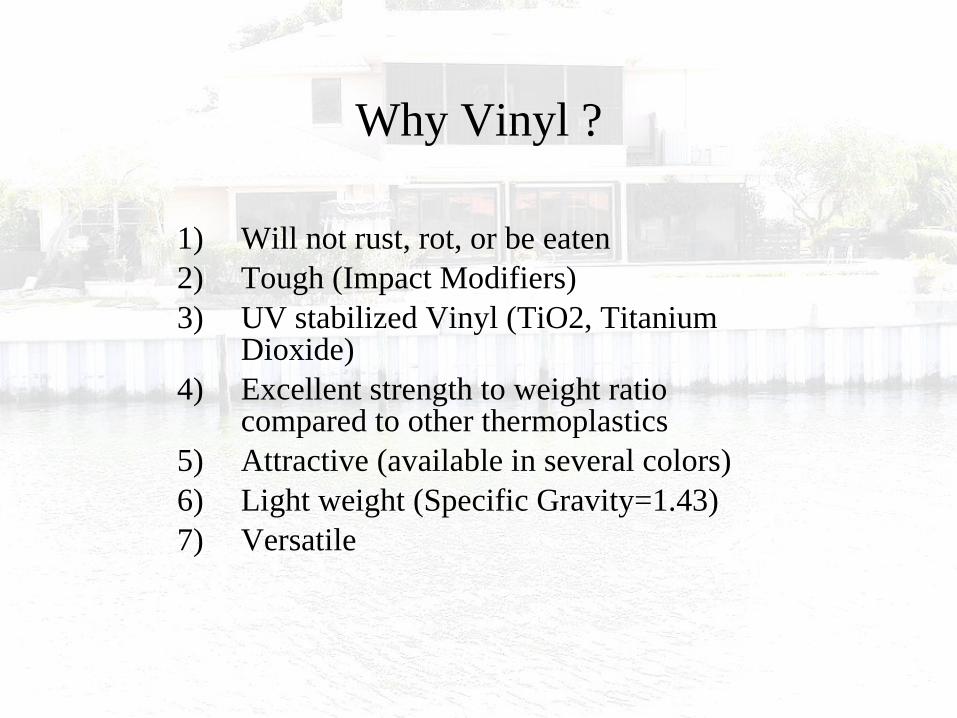
Why Vinyl ?
1) Will not rust, rot, or be eaten2) Tough (Impact Modifiers)3) UV stabilized Vinyl (TiO2, Titanium
Dioxide)4) Excellent strength to weight ratio
compared to other thermoplastics5) Attractive (available in several colors)6) Light weight (Specific Gravity=1.43)7) Versatile

Shallow Water

Shallow Water


Dropped Wale


Drop wale when wall is too tall

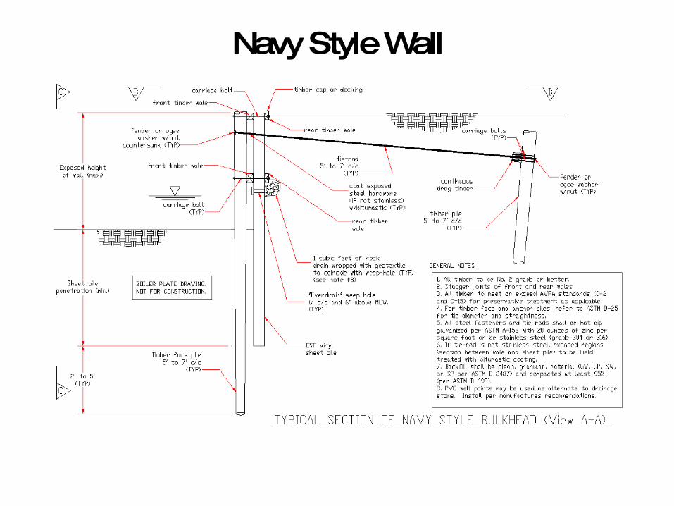
Navy Style Wall


TimberGuard
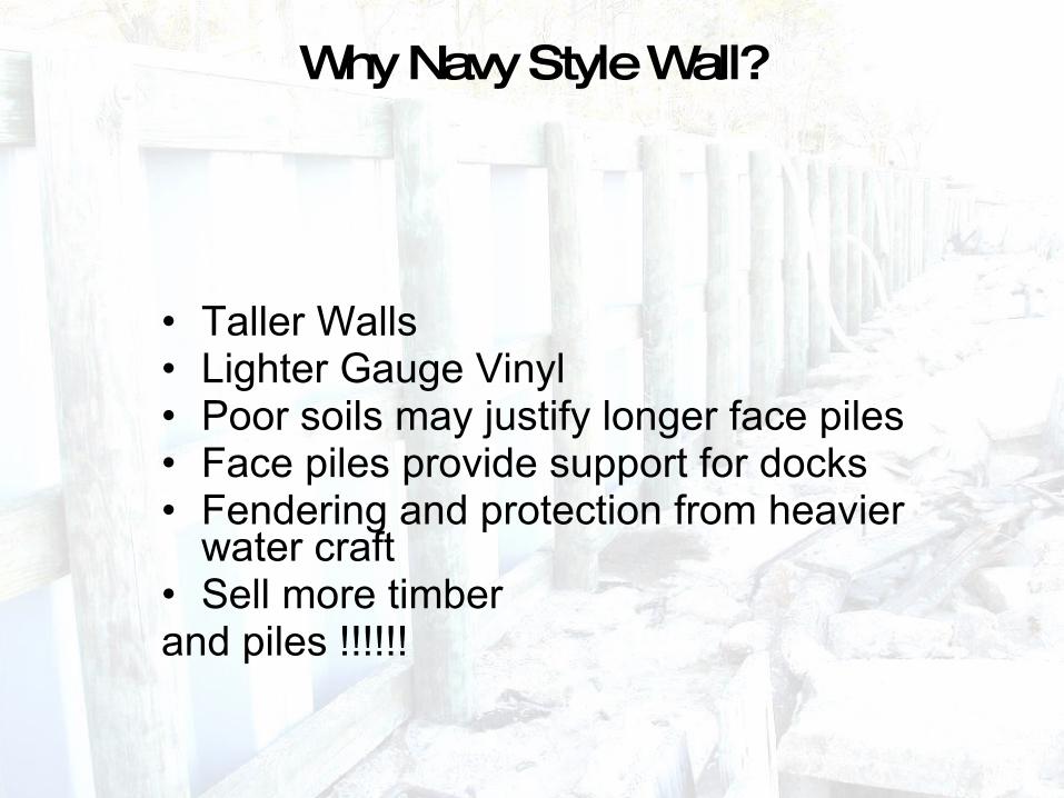
Why Navy Style Wall?
• Taller Walls• Lighter Gauge Vinyl• Poor soils may justify longer face piles• Face piles provide support for docks• Fendering and protection from heavier
water craft• Sell more timber and piles !!!!!!

Cap Options
•

Timber, Timber, Timber, and did we mention Timber ?

Timber Cap / Wale

Synthetic Deck
•
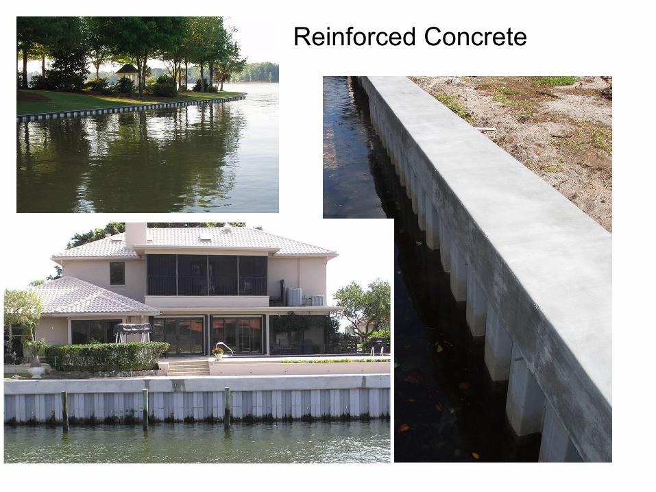
Reinforced Concrete
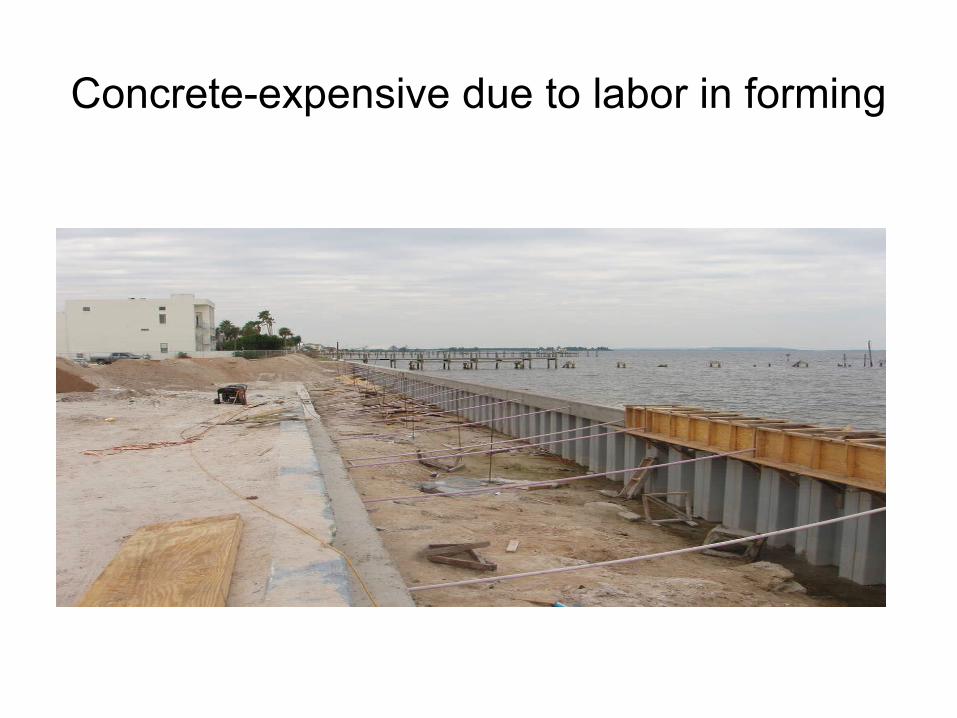
Concrete-expensive due to labor in forming

EverCap (Aluminum)

EverCap
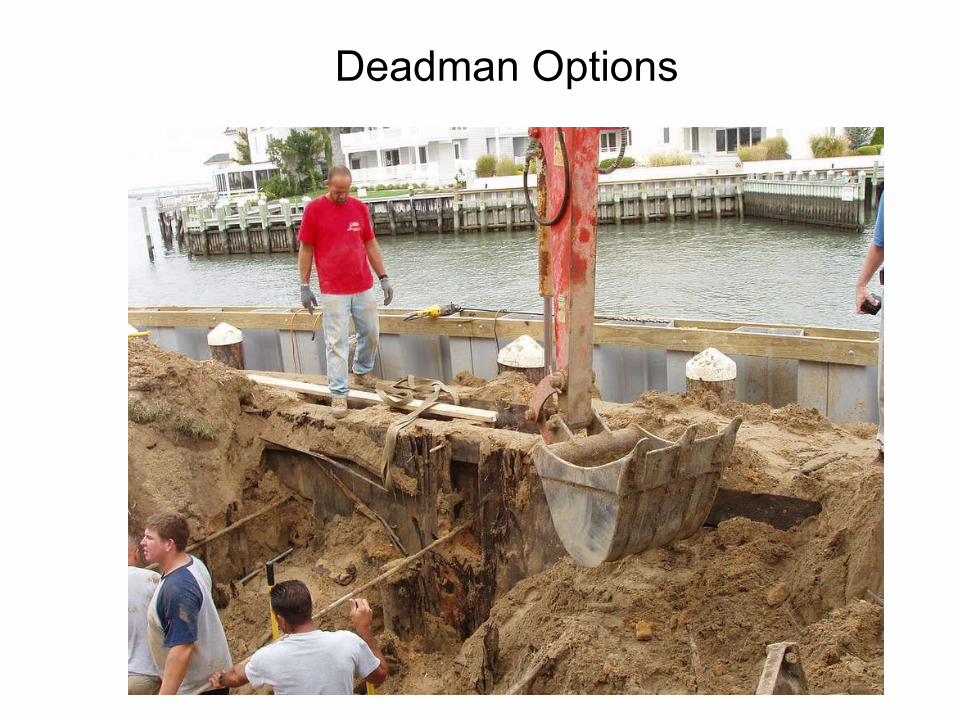
Deadman Options

Timber Piles w/ Drag Plank
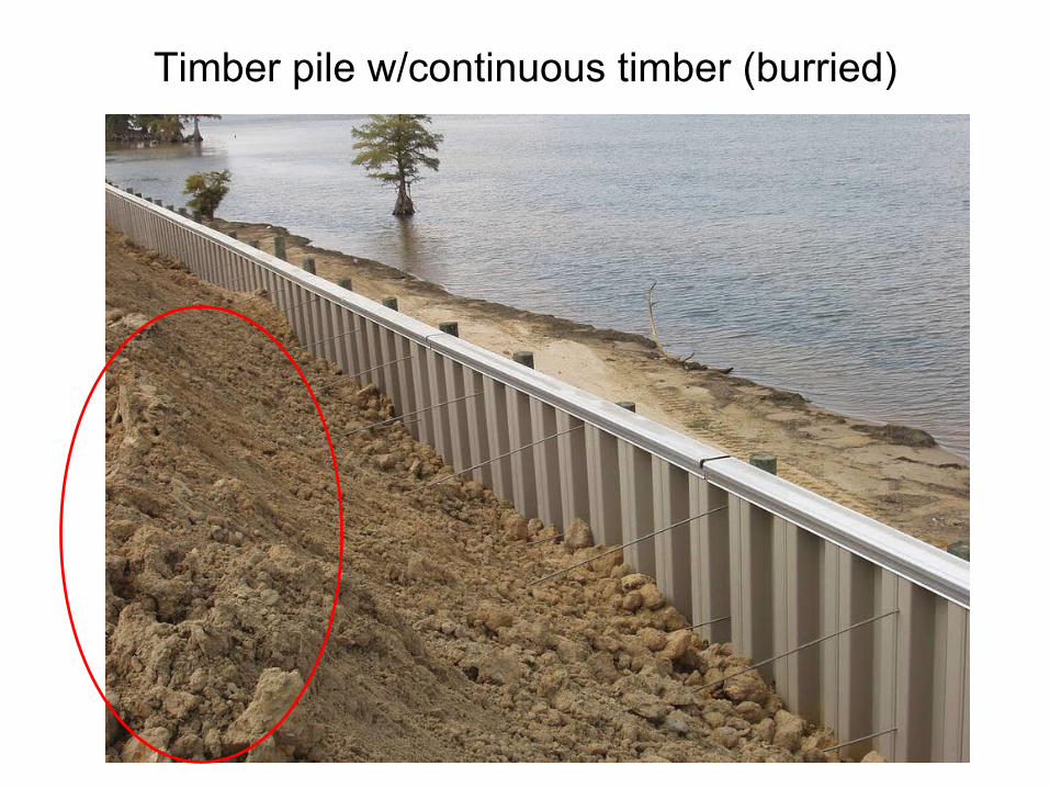
Timber pile w/continuous timber (burried)

Reinforced Concrete

Tools and installation equipment
• Vibratory hammer• Rail Jet• Water jet• Collins Hammer• Drop Hammer• Trenching• Mandrel

Driving Guide !!!!!!!!!
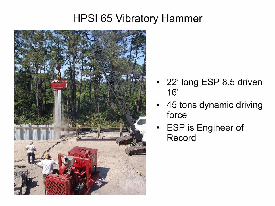
HPSI 65 Vibratory Hammer
• 22’ long ESP 8.5 driven 16’
• 45 tons dynamic driving force
• ESP is Engineer of Record

Water Jet

Many uses for Vinyl sheet pile
• Seawalls and Bulkheads• Wave Breaks• Cut-off Walls – Civil and
Environmental• Levee raising• Detension Ponds

Manufacturing
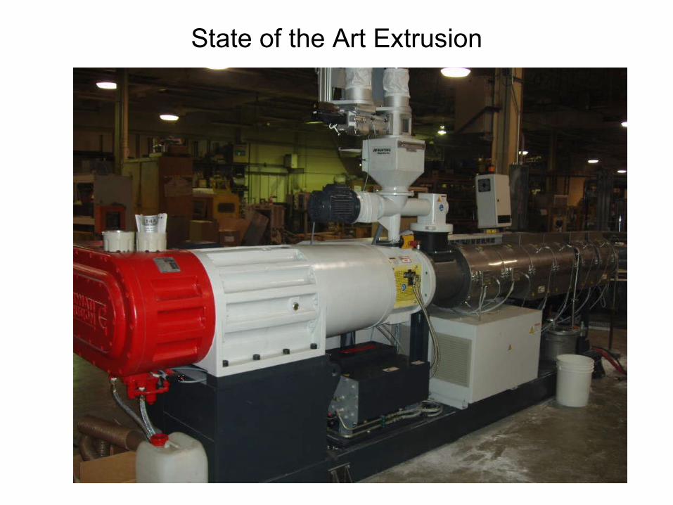
State of the Art Extrusion

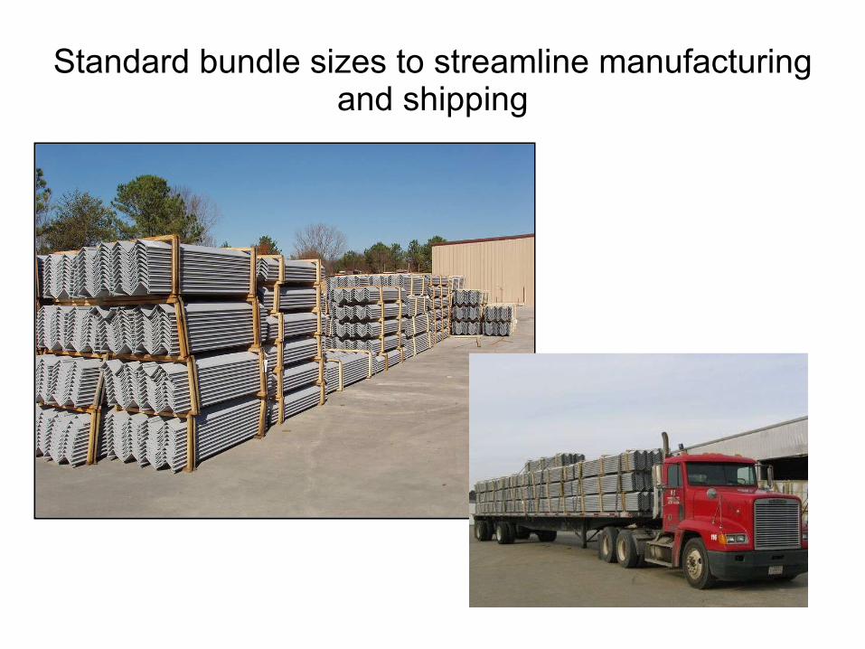
Standard bundle sizes to streamline manufacturing and shipping

Standard Bundle Dimensions
• ESP 3.5 – 40 pieces• ESP 4.1 – 20 pieces• ESP 8.5 – 12 pieces
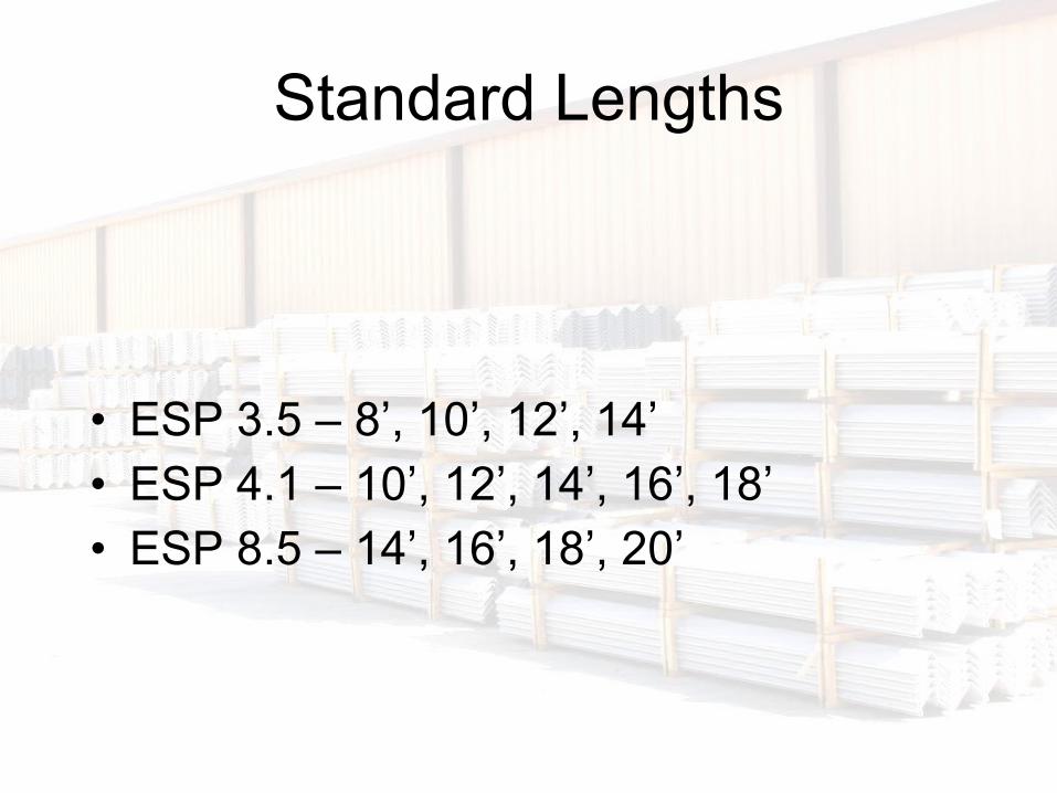
Standard Lengths
• ESP 3.5 – 8’, 10’, 12’, 14’• ESP 4.1 – 10’, 12’, 14’, 16’, 18’• ESP 8.5 – 14’, 16’, 18’, 20’

QA/QC Labels


Commitment to Quality Manufacturing
• State of the art co-extrusion technology• Unparalleled Quality Control• Unlimited capacity• Huge buying power of raw materials• Working inventory of stock lengths

Corners
• Universal Corner – fits 2.1, 3.5, and 4.1
• 8.5 Corner – fits 8.5

Vs. ESP 8.5 – Two wales

Engineering Behind the Sheet Pile
November 6, 2006

How does a “part” achieve its strength?
1) “Material” that it is made from (e.g. steel, wood, concrete, vinyl, aluminum, etc.)
3) Geometric Properties or shape (e.g. thickness, area, section modulus, moment of inertia, radius of gyration, etc.)

MATERIAL PROPERTIES

STRESS (σ)
σ = P/A
Where,σ = stress (psi)P = Applied Force or Load (lbs)A = Area that it is applied over (in2)

Types of stresses

Strain (ε) and Modulus (E)
Strain is “deformation” of a material given a certain stress. Relationship between stress and strain defines the materials stiffness, which is usually referred to as Modulus of Elasticity (or Young’s Modulus)

Stress – Strain Curve
σ
ε
= * Eσ εHooke’s Law

Stress-strain for various materials
ε
σ

GEOMETRIC PROPERTIES
• Moment of Inertia (I) – measure of a shapes bending stiffness. Usually in units of in4
• Section Modulus (Z or S) – measure of a shapes ability to resist bending. Related to I (see equation). Usually in units of in3
• Neutral Axis – axis where stress is zero (the geometric center for a symmetric part)
• Distance from the neutral axis to the outermost stress fiber (c). Usually measured in inches

Example

Strength of the Part
• Combining aspects of the material properties and the geometric properties
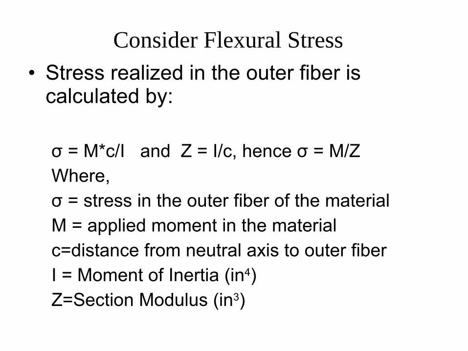
Consider Flexural Stress• Stress realized in the outer fiber is
calculated by:
σ = M*c/I and Z = I/c, hence σ = M/ZWhere,σ = stress in the outer fiber of the materialM = applied moment in the materialc=distance from neutral axis to outer fiberI = Moment of Inertia (in4)Z=Section Modulus (in3)
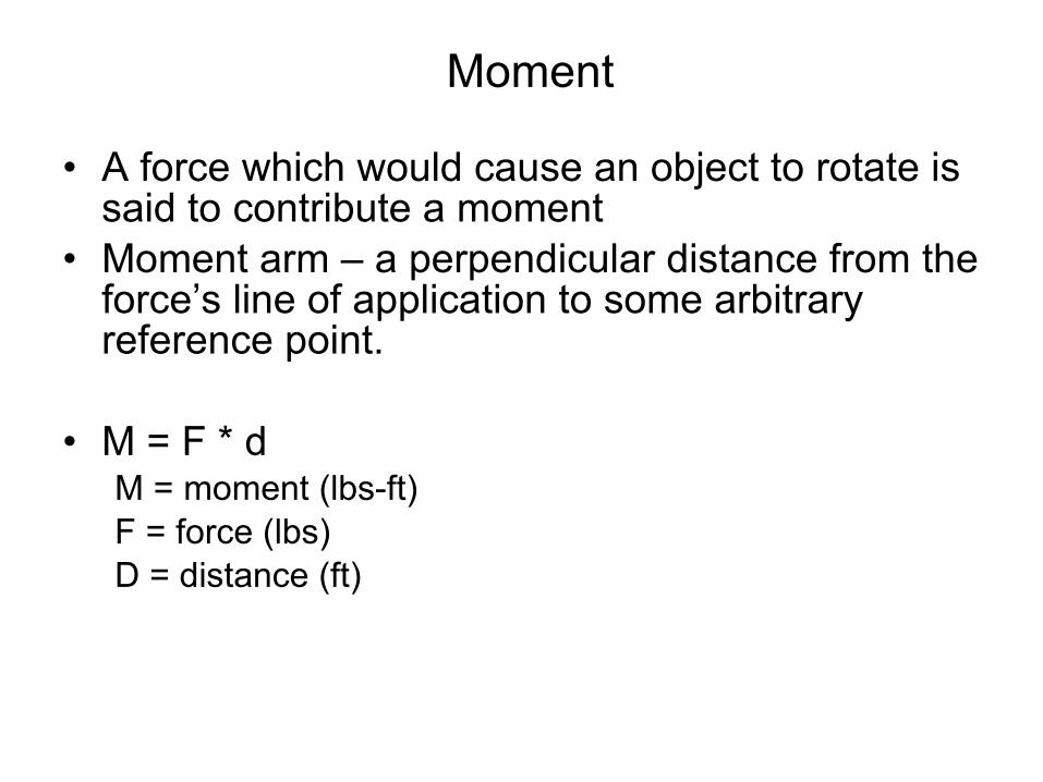
Moment
• A force which would cause an object to rotate is said to contribute a moment
• Moment arm – a perpendicular distance from the force’s line of application to some arbitrary reference point.
• M = F * dM = moment (lbs-ft)F = force (lbs)D = distance (ft)

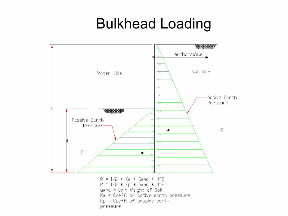
Bulkhead Loading

Variables that Impact Loading
• Wall Height• Soils• Water Level and Tide Fluctation• Slopes in front and behind the wall

How and When to Utilize Engineering

Everlast Engineering
• Licensed in Multiple States
• Over 2,000 Sign and Sealed projects in the ground
• Hands on design / build plans
• Assistance with Engineering

Learned from mistakes of others
Charlie, Ivan, Katrina, and others


