36
SECA Coal-Based System Program Nguyen Minh GE Global Research Torrance, CA 7 th Annual SECA Workshop and Peer Review Meeting Philadelphia, PA September 12-14, 2006

SECA Coal-Based System Program
Nguyen MinhGE Global ResearchTorrance, CA
7th Annual SECA Workshop and Peer Review MeetingPhiladelphia, PASeptember 12-14, 2006
2SECA Coal Based Systems
7th SECA Annual Workshop September 2006
SECA Coal Based System Program
• Completed SECA SOFC Program Phase I September 2005 and started SECA Phase II
• Initiated SOFC Coal Based Power Systems Program September 2006• Combined the two programs into the program “SECA Coal based
System”
3SECA Coal Based Systems
7th SECA Annual Workshop September 2006
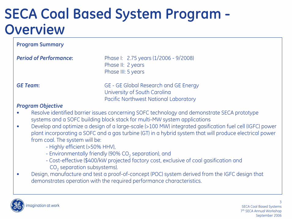
SECA Coal Based System Program -Overview
Program Summary
Period of Performance: Phase I: 2.75 years (1/2006 - 9/2008)Phase II: 2 years Phase III: 5 years
GE Team: GE - GE Global Research and GE EnergyUniversity of South CarolinaPacific Northwest National Laboratory
Program Objective• Resolve identified barrier issues concerning SOFC technology and demonstrate SECA prototype
systems and a SOFC building block stack for multi-MW system applications• Develop and optimize a design of a large-scale (>100 MW) integrated gasification fuel cell (IGFC) power
plant incorporating a SOFC and a gas turbine (GT) in a hybrid system that will produce electrical power from coal. The system will be:
- Highly efficient (>50% HHV), Environmentally friendly (90% CO2 separation), and Cost-effective ($400/kW projected factory cost, exclusive of coal gasification and
CO2 separation subsystems).• Design, manufacture and test a proof-of-concept (POC) system derived from the IGFC design that
demonstrates operation with the required performance characteristics.
4SECA Coal Based Systems
7th SECA Annual Workshop September 2006
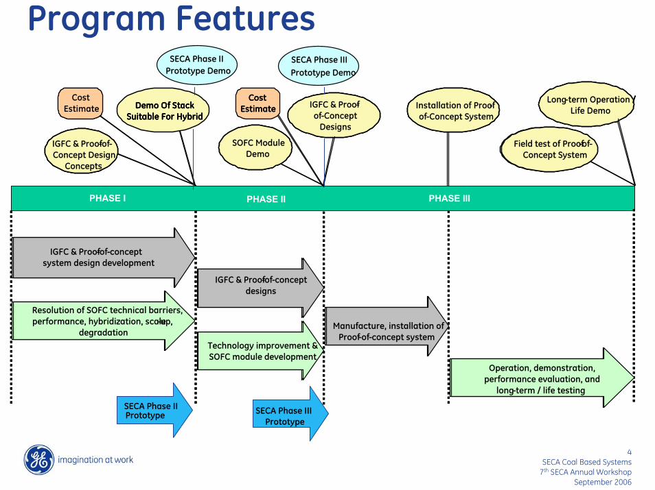
Program Features
PHASE I PHASE II PHASE III
CostEstimate
CostEstimate Demo Of Stack
Suitable For Hybrid
IGFC & Proof-of-Concept Design
Concepts
SOFC Module Demo
IGFC & Proof-of-Concept
Designs
Installation of Proof-of-Concept System
Long-term Operation / Life Demo
Field test of Proof-of-Concept System
Resolution of SOFC technical barriers, performance, hybridization, scale-up,
degradation
IGFC & Proof-of-concept system design development
IGFC & Proof-of-concept designs
Technology improvement & SOFC module development
Manufacture, installation of Proof-of-concept system
Operation, demonstration, performance evaluation, and
long-term / life testing
PHASE I PHASE II PHASE III
CostEstimate
CostEstimate
CostEstimate
CostEstimate Demo Of Stack
Suitable For HybridDemo Of Stack
Suitable For Hybrid
IGFC & Proof-of-Concept Design
Concepts
IGFC & Proof-of-Concept Design
Concepts
SOFC Module Demo
SOFC Module Demo
IGFC & Proof-of-Concept
Designs
IGFC & Proof-of-Concept
Designs
Installation of Proof-of-Concept System
Installation of Proof-of-Concept System
Long-term Operation / Life Demo
Long-term Operation / Life Demo
Field test of Proof-of-Concept System
Field test of Proof-of-Concept System
Resolution of SOFC technical barriers, performance, hybridization, scale-up,
degradation
IGFC & Proof-of-concept system design development
IGFC & Proof-of-concept designs
Technology improvement & SOFC module development
Manufacture, installation of Proof-of-concept system
Operation, demonstration, performance evaluation, and
long-term / life testing
SECA Phase II Prototype Demo Prototype Demo
SECA Phase III
SECA Phase II Prototype SECA Phase III
Prototype

5SECA Coal Based Systems
7th SECA Annual Workshop September 2006
Presentation Outline
• SECA prototype demonstration• SOFC stack technology• System concept development

6SECA Coal Based Systems
7th SECA Annual Workshop September 2006
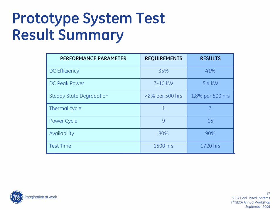
Prototype Demonstration - Highlights
1720 hrs1500 hrsTest Time
90%80%Availability
159Power Cycle
31Thermal cycle
1.8% per 500 hrs<2% per 500 hrsSteady State Degradation
5.4 kW3-10 kWDC Peak Power
41%35%DC Efficiency
RESULTSREQUIREMENTSPERFORMANCE PARAMETER
HIGHLIGHTS
• 2005: Demonstrated a SECA prototype system that met/exceeded key DOE minimum requirements
•41% peak efficiency•5.4 kW peak power, ATR fuel•Projected mfg cost < $800/kW•System tested ~1700h at GE
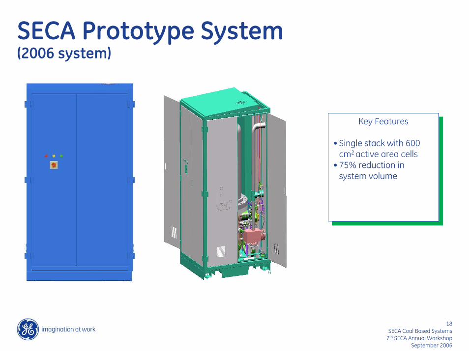
• 2006: Prototype system – 75% reduction in system volume
•49% peak efficiency•5.6 kW peak power, ATR fuel•ATR fuel•Projected mfg cost < $600/kW•System to be tested at NETL

7SECA Coal Based Systems
7th SECA Annual Workshop September 2006
Stack Technology - Highlights
0
0.2
0.4
0.6
0.8
1
0 400 800 1200 1600 2000 2400 2800 3200Time, Hours
Ave
rage
Cel
l Vol
tage
, V
3-cell stackTemperature: 800oC
Power outage
Degradation rate:: ~0.8%/1000 hrs
Degradation rate: ~1.3%/1000 hrs
HIGHLIGHTS
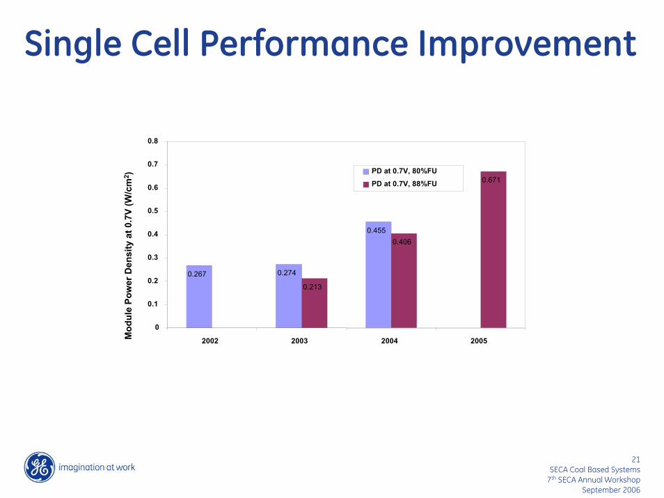
• Single cell performance improvement and cell size scaleup demonstration
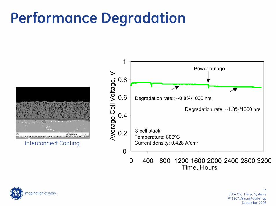
• Performance degradation rate 1.0-1.5%/1000 hours
• Multicell stack demonstration (height and footprint area)
• Stack operation under pressures
0.5
0.6
0.7
0.8
0.9
0.2 0.3 0.4 0.5 0.6
Current Density, mA/cm2
Cel
l Vol
tage
, V
14.7 psia with SR29.4 psia with SR49.1 psia with SR58.8 psia with SR
8SECA Coal Based Systems
7th SECA Annual Workshop September 2006
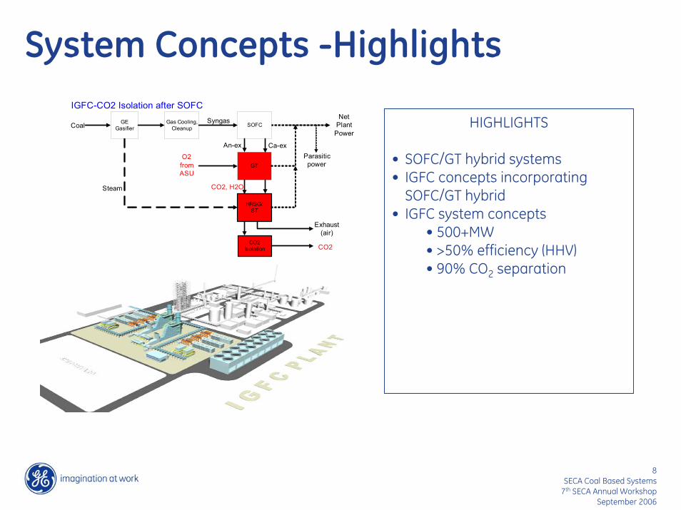
System Concepts -Highlights
HIGHLIGHTS
• SOFC/GT hybrid systems• IGFC concepts incorporating
SOFC/GT hybrid• IGFC system concepts
• 500+MW• >50% efficiency (HHV)• 90% CO2 separation
GEGasifier
GT
HRSG/ST
CoalSyngas
Steam
Gas Cooling,Cleanup
Parasiticpower
NetPlant
PowerSOFC
IGFC-CO2 Isolation after SOFC
Exhaust(air)
An-ex Ca-ex
CO2Isolation CO2
CO2, H2O
O2fromASU
SECA Prototype Demonstration
10SECA Coal Based Systems
7th SECA Annual Workshop September 2006
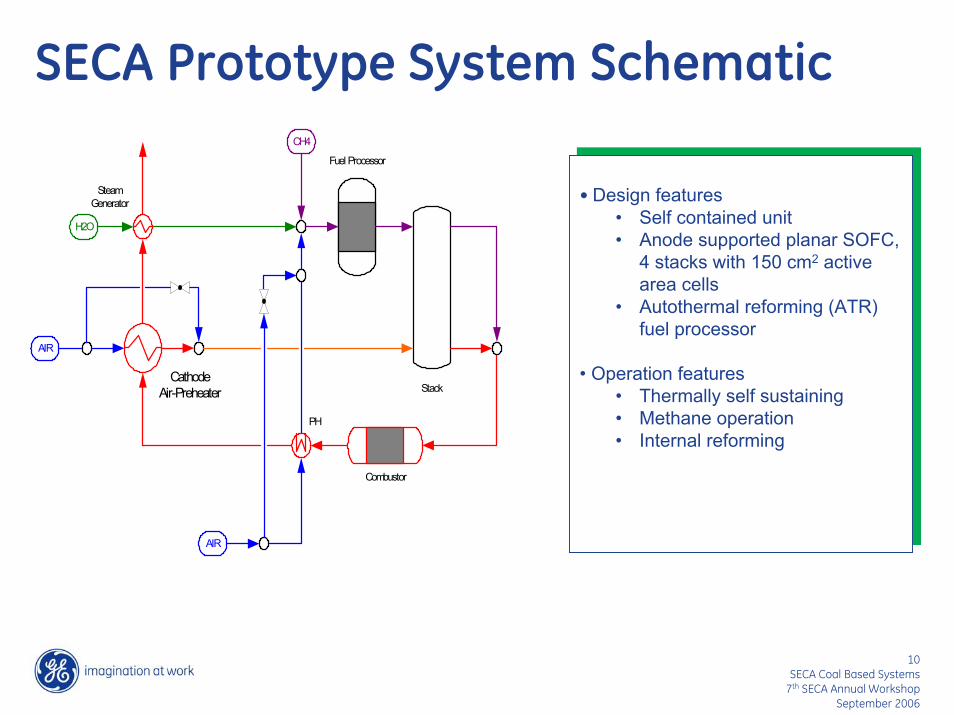
SECA Prototype System Schematic
CathodeAir-Preheater
Fuel Processor
Stack
PH
SteamGenerator
Combustor
AIR
AIR
H2O
CH4
• Design features• Self contained unit• Anode supported planar SOFC,
4 stacks with 150 cm2 active area cells
• Autothermal reforming (ATR) fuel processor
• Operation features• Thermally self sustaining • Methane operation• Internal reforming
• Design features• Self contained unit• Anode supported planar SOFC,
4 stacks with 150 cm2 active area cells
• Autothermal reforming (ATR) fuel processor
• Operation features• Thermally self sustaining • Methane operation• Internal reforming

11SECA Coal Based Systems
7th SECA Annual Workshop September 2006
Prototype System
PROTOTYPE SYSTEMSOFC STACK
ATR FUEL PROCESSOR
CATHODE AIR BLOWER

12SECA Coal Based Systems
7th SECA Annual Workshop September 2006
Prototype System Test Plan
0 200 400 600 800 1000 1200 1400 1600 1800 2000
Test Time (h)
Fuel
Cel
l Sys
tem
Net
Pow
er
Steady State Test 1
Transient Test and Scheduled Maintenance Steady State Test 2
Efficiency Demonstration, Peak Efficiency Operation
Peak Power Demonstration &
Operation
Efficiency Demonstration, Peak Efficiency
Operation
System Startup and Initial
Performance Test
Further testing as desired, and
system shutdown
End of Phase I Required Testing

13SECA Coal Based Systems
7th SECA Annual Workshop September 2006
Prototype System Operation
14SECA Coal Based Systems
7th SECA Annual Workshop September 2006
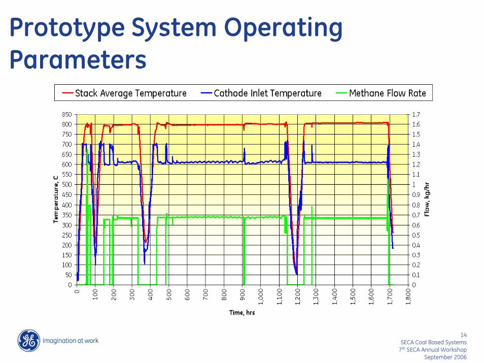
Prototype System Operating Parameters

15SECA Coal Based Systems
7th SECA Annual Workshop September 2006
Cell Voltages at Peak Efficiency Point
0
0.1
0.2
0.3
0.4
0.5
0.6
0.7
0.8
0.9
0 5 10 15 20 25 30 35 40
Cell #
Cel
l Vol
tage
(V)
S1S2S3S4
16SECA Coal Based Systems
7th SECA Annual Workshop September 2006
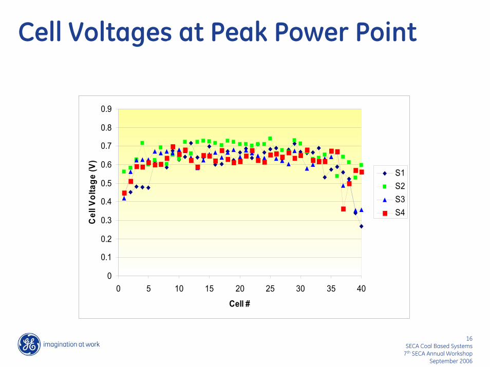
Cell Voltages at Peak Power Point
0
0.1
0.2
0.3
0.4
0.5
0.6
0.7
0.8
0.9
0 5 10 15 20 25 30 35 40
Cell #
Cel
l Vol
tage
(V)
S1S2S3S4
17SECA Coal Based Systems
7th SECA Annual Workshop September 2006
Prototype System TestResult Summary
1720 hrs1500 hrsTest Time
90%80%Availability
159Power Cycle
31Thermal cycle
1.8% per 500 hrs<2% per 500 hrsSteady State Degradation
5.4 kW3-10 kWDC Peak Power
41%35%DC Efficiency
RESULTSREQUIREMENTSPERFORMANCE PARAMETER
18SECA Coal Based Systems
7th SECA Annual Workshop September 2006
SECA Prototype System(2006 system)
Key Features
• Single stack with 600 cm2 active area cells
• 75% reduction in system volume
Key Features
• Single stack with 600 cm2 active area cells
• 75% reduction in system volume

19SECA Coal Based Systems
7th SECA Annual Workshop September 2006
Preliminary Test Results
PRELIMINARY RESULTS•Peak efficiency 49%
• Net DC power 3.2 kW• ATR fuel• Fuel utilization 80%• Air utilization 24%
•Peak power of 5.6 kW• Efficiency of 32%• ATR fuel• Fuel utilization 65%• Air utilization 21%
PRELIMINARY RESULTS•Peak efficiency 49%
• Net DC power 3.2 kW• ATR fuel• Fuel utilization 80%• Air utilization 24%
•Peak power of 5.6 kW• Efficiency of 32%• ATR fuel• Fuel utilization 65%• Air utilization 21%

SOFC Stack Technology
21SECA Coal Based Systems
7th SECA Annual Workshop September 2006
Single Cell Performance Improvement
Mod
ule
Pow
er D
ensi
ty a
t 0.7
V (W
/cm
2 ) 0.671
0.267 0.274
0.455
0.213
0.406
0
0.1
0.2
0.3
0.4
0.5
0.6
0.7
0.8
2002 2003 2004 2005
PD at 0.7V, 80%FU
PD at 0.7V, 88%FU

22SECA Coal Based Systems
7th SECA Annual Workshop September 2006
Cell Size Scaleup
2.5 cm10 cm 16 cm 31 cm 40 cm
Tape Calendering Plasma Spraying
23SECA Coal Based Systems
7th SECA Annual Workshop September 2006
Performance Degradation
1200 1600 2000Time, Hours
Ave
rage
Cel
l Vol
tage
, V
3-cell stackTemperature: 800oCCurrent density: 0.428 A/cm2
Power outage
Degradation rate:: ~0.8%/1000 hrs
Degradation rate: ~1.3%/1000 hrs
Interconnect Coating
1
0.8
0.6
0.4
0.2
00 400 800 2400 2800 3200

24SECA Coal Based Systems
7th SECA Annual Workshop September 2006
Performance of 20-Cell Stack
10.00
11.00
12.00
13.00
14.00
15.00
0.300 0.320 0.340 0.360 0.380 0.400 0.420
Stac
k Vo
ltage
(V
)
0.100
0.150
0.200
0.250
0.300
0.350
0.400
0.450
0.500
0.550
Pow
er D
ensi
ty (
W/c
m2 )
Stack Voltage, 64% H2 (V)
Stack Voltage, ATR Fuel (V)
Power Density, 64% H2 (W/cm2)
Power Density, ATR Fuel (W/cm2)
T=800C
16.00
Current Density (A/cm2)
0.600
600-cm2 active area cells

25SECA Coal Based Systems
7th SECA Annual Workshop September 2006
Multicell Stack Performance
0.100
0.200
0.300
0.400
0.500
0.600
0.700
0.800
0.900
Stac
k Vo
ltage
V
0.000
0.050
0.100
0.150
0.200
0.250
0.300
0.350
0.400
0.450
0.500
Pow
er D
ensi
ty
(W/c
m2 )
20cell 600 cm2 Stack, Stack Voltage V 40cell 150 cm2 Stack, Stack Voltage V 20cell 600 cm2 Stack, Power Density (W/cm2) 40cell 150 cm2 Stack, Power Density (W/cm2)
80% Fuel Utilization ATR Fuel, T=800C
0.100 0.150 0.200 0.250 0.300 0.350 0.400 0.450 0.500
Current Density (A/cm2)

26SECA Coal Based Systems
7th SECA Annual Workshop September 2006
Pressurized Stack Testing
0.5
0.6
0.7
0.8
0.9
0.2 0.3 0.4 0.5 0.6
Current Density, mA/cm2
Cel
l Vol
tage
, V
14.7 psia with SR29.4 psia with SR49.1 psia with SR58.8 psia with SR
T=8000CSR=Simulated steam reformateCell active area= 150 cm2

27SECA Coal Based Systems
7th SECA Annual Workshop September 2006
Pressurized OperationStack with 600 cm2 active area cells
0.0
0.2
0.4
0.6
0.8
1.0
1.2
0.00 0.20 0.40 0.60
Current Density, A/cm22
Ave
rage
Cel
l Vol
tage
, V
0%
10%
20%
30%
40%
50%
60%
Fuel
Util
izat
ion,
%
14.7 psia30 psia45 psia60 psiaFuel Utilization
0.5
0.6
0.7
0.8
0.9
0.10 0.20 0.30 0.40
Current Density, A/cm2A
vera
ge C
ell V
olta
ge, V
60%FU 37%H2
60%FU SR Fuel
70%FU SR Fuel
75%FU SR Fuel
System Concept Development
29SECA Coal Based Systems
7th SECA Annual Workshop September 2006
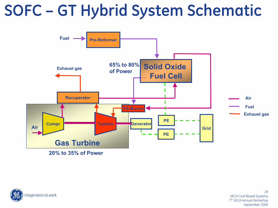
SOFC – GT Hybrid System Schematic
Solid Oxide Fuel Cell
Compr Turbine
PE
Generator
Recuperator
TG Burner
PE
GridAir
Exhaust gas
Pre-ReformerFuel
Gas Turbine20% to 35% of Power
65% to 80% of Power
Air
Exhaust gas
Fuel

30SECA Coal Based Systems
7th SECA Annual Workshop September 2006
Efficiency Improvements with Hybrid Configurations
5258 kW4585 kW3320 kWNet Plant Power
4.6 atm4.6 atm1.3 atmSOFC Pressure
(389 kW)
0
3709
44.8
Simple
(100 kW)
976
3709
61.1
Hybrid Hybrid with Recycle
(288 kW)Parasitic Power
1447GT Power* (kW)
4099SOFC Power* (kW)
71.0Efficiency (%)
• Natural gas
• 800C planar SOFC *After power conversion

31SECA Coal Based Systems
7th SECA Annual Workshop September 2006
IGFC System
IGFC System• System feautres
• SOFC/gas turbine hybrid• CO2 separation (with or
without•Key system components
• SOFC• Gasifier• Gas turbine and steam
turbine
IGFC System• System feautres
• SOFC/gas turbine hybrid• CO2 separation (with or
without•Key system components
• SOFC• Gasifier• Gas turbine and steam
turbine
Gasifier
Fuel Cells
HRSG
Water Gas Shift
Combustor
Gas Clean-upCoal Raw Syngas
Steam
Steam
Generator
Air
GT C
Steam
STGenerator
Exhaust
CO2 SeparationSpentFuel Recycle

32SECA Coal Based Systems
7th SECA Annual Workshop September 2006
IGFC Plant Concept
Targets and Features• 500+ MW• 50% Efficiency (HHV)• ~$400/kW mfg cost (power block)• 5-10% CoE advantage over IGCC• Low emissions• CO2 sequestration capable
33SECA Coal Based Systems
7th SECA Annual Workshop September 2006
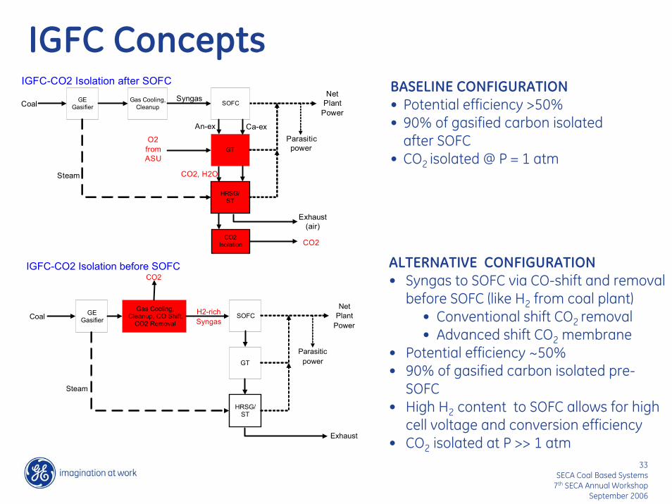
IGFC ConceptsGE
Gasifier
GT
HRSG/ST
CoalSyngas
Steam
Gas Cooling,Cleanup
Parasiticpower
NetPlant
PowerSOFC
IGFC-CO2 Isolation after SOFC
Exhaust(air)
An-ex Ca-ex
CO2Isolation CO2
CO2, H2O
O2fromASU
GEGasifier
GT
HRSG/ST
Coal H2-richSyngas
Steam
Gas Cooling,Cleanup, CO Shift,
CO2 Removal
Parasiticpower
NetPlant
PowerSOFC
IGFC-CO2 Isolation before SOFC
Exhaust
CO2ALTERNATIVE CONFIGURATION• Syngas to SOFC via CO-shift and removal
before SOFC (like H2 from coal plant)• Conventional shift CO2 removal• Advanced shift CO2 membrane
• Potential efficiency ~50% • 90% of gasified carbon isolated pre-
SOFC• High H2 content to SOFC allows for high
cell voltage and conversion efficiency• CO2 isolated at P >> 1 atm
BASELINE CONFIGURATION• Potential efficiency >50% • 90% of gasified carbon isolated
after SOFC• CO2 isolated @ P = 1 atm
34SECA Coal Based Systems
7th SECA Annual Workshop September 2006
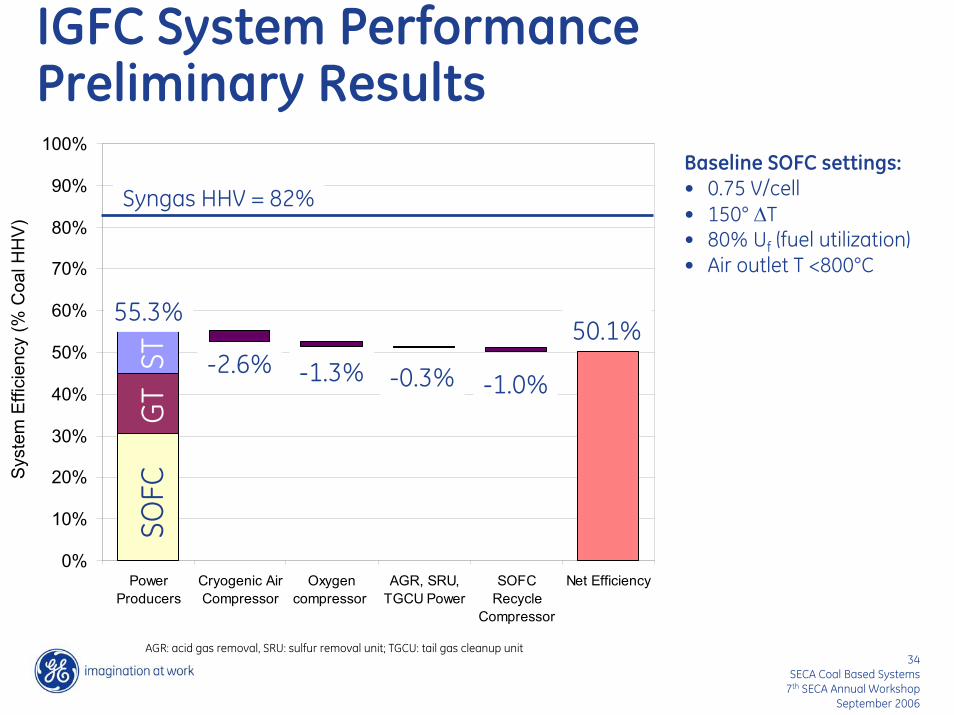
IGFC System PerformancePreliminary Results
0%
10%
20%
30%
40%
50%
60%
70%
80%
90%
100%
PowerProducers
Cryogenic AirCompressor
Oxygencompressor
AGR, SRU,TGCU Power
SOFCRecycle
Compressor
Net Efficiency
Sys
tem
Effi
cien
cy (%
Coa
l HH
V)
SOFC
GT
ST
55.3%50.1%
-2.6% -1.3% -0.3% -1.0%
Syngas HHV = 82%Baseline SOFC settings:• 0.75 V/cell• 150° ∆T• 80% Uf (fuel utilization)• Air outlet T <800°C
AGR: acid gas removal, SRU: sulfur removal unit; TGCU: tail gas cleanup unit

35SECA Coal Based Systems
7th SECA Annual Workshop September 2006
Concluding Remarks
• Successful SECA prototype system demonstration• Significant progress on stack technology development for hybrid
SOFC/GT systems• Focus on IGFC system development
36SECA Coal Based Systems
7th SECA Annual Workshop September 2006
Acknowledgments
• Travis Shultz, Wayne Surdoval, Don Collins of DOE/NETL• GE Fuel Cell Team• The material presented was prepared with the support of the U.S.
Department of Energy, under Award No. DE-FC26-01NT41245 and DE-FC26-05NT42614. However, any opinions, findings, conclusions, or recommendations expressed herein are those of the author and do not necessarily reflect the views of the DOE.

![1 Eric Grol SystemAnalysis.ppt [Read-Only] library/events/2008/seca... · • Single pass SOFC ... Boiler Feedwater Supercritical Steam Condenser Steam Turbine Air Heat Recovery N](https://static.documents.pub/doc/80x56/5abaa5427f8b9a76038bc126/1-eric-grol-read-only-libraryevents2008seca-single-pass-sofc-boiler.jpg)


