1. INTRODUCTIONThe use of integrated-optical structures to enhance non-linear effects, in particular, second-harmonic generation(SHG), is attractive because of the high optical power den-sities and long interaction lengths provided by guided-wave structures.1 Moreover, they have another advan-tage in that all the components of the second-ordernonlinear-optical coefficient tensor are, in principle,phase matchable by use of the modal dispersion inwaveguiding structures. SHG in optical waveguides isclassified into two types: One is conversion from aguided mode at the fundamental frequency into a second-harmonic (SH) guided mode (guided–guided type ofSHG2–5), and the other is conversion from a guided modeat the fundamental frequency into a SH radiation mode(so-called Cerenkov-type SHG6–11). The guided–guidedSHG has a large efficiency, but phase matching for agiven wavelength requires critical control and uniformityof the waveguide dimensions.Cerenkov-type SHG is free from the phase-matching
constraint because this scheme uses radiation modeswhose propagation constants can take arbitrary values.This type of SHG occurs when the phase velocity of thenonlinear SH polarization is larger than that of the freeSH wave in the cladding material (substrate). Thephase-matched SH wave is radiated into the substrate atan angle that satisfies the conservation of the wave-vectorcomponent parallel to the waveguide. The disadvantageof Cerenkov-type SHG is a reduction in efficiency becauseof a small overlap of the modal fields of the fundamentalwave and the SH wave. The Cerenkov radiation schemewas demonstrated experimentally (see, for example, Refs.6–9).Interest in Cerenkov-type SHG has been generated by
potential applications in short-wavelength light sources,generation of ultrashort SH pulses,12 and all-opticalswitching by a x(2):x(2) cascading process.13
A leaky wave can propagate off axis in an anisotropic
waveguide.14,15 The phenomenon of leaky-wave propaga-tion in optical waveguides has been studied exten-sively.16–22 For waveguides on the X- and Y-cut surfacesof negative crystals a leaky wave is the wave of hybrid po-larization with an effective refractive index that is lessthan the substrate’s ordinary refractive index. The fieldof a leaky wave consists of two contributions with or-thogonal polarization. The contribution of the extraordi-nary polarization concentrates its power in the wave-guide. The contribution of the ordinary polarization hasa radiative part, which is responsible for a leakage of themode’s power into the substrate.Here we show how the Cerenkov-type SHG process is
modified if a leaky wave of an anisotropic waveguide is in-volved in the interaction. Assuming an anisotropicwaveguide with an arbitrary graded-index distributioninside the waveguide layer, I present numerical resultson an overlap integral that is responsible for the SHG ef-ficiency and the spatial distribution of the radiation field.
2. MODELWe consider a planar graded-index waveguide on theX-cut surface of a negative crystal [Fig. 1(a)] and a geom-etry in which the crystal optical axis Z is placed in thewaveguide plane, forming an angle u with propagation di-rection z of the guided mode at the fundamental fre-quency v. We assume that an anisotropy (no 2 ne) islarge compared with typical graded-index refractive-index (RI) changes. (Here no and ne are the substrate’s or-dinary and extraordinary RI’s, respectively.) In this casethe hybrid waveguide modes are still mostly ordinary andextraordinary. The hybrid quasi-ordinary (quasi-TM)modes propagate as guided modes at any direction of thewaveguide, whereas the hybrid quasi-extraordinary(quasi-TE) modes become leaky waves if their propaga-tion angles u are greater than the critical angles uc andtheir effective RI’s NTE(u) , no . The critical angle is de-fined by the condition that NTE(uc) 5 no .
1997 Optical Society of America
332 J. Opt. Soc. Am. B/Vol. 14, No. 2 /February 1997 D. V. Petrov
The effective RI of a leaky wave is a complex number,and its imaginary part describes a loss of mode energy inthe waveguide as a result of its radiation in thesubstrate.15–17 The loss coefficient is maximum near uc ,and it decreases with u.Usually the ordinary and the extraordinary RI’s have
different dispersion. Let the ordinary RI at v nov be
larger than the extraordinary RI at the double frequencyn e2v [see Fig. 1(b)]. (For example, in LiNbO3 this condi-
tion is satisfied in the near-infrared region for wave-lengths more than 1.1 mm.23) Assume that the wave at vis a guided quasi-TM mode. As Fig. 1(b) shows, allmodes at 2v with propagation constants bR
2v , ko2vno
2v
belong to radiation modes with continuous spectra of bR2v.
The wave-vector matching of the guided mode at v to theSH radiation mode exists for any propagation angle (theCerenkov-type SHG process).The effective RI of the leaky wave at 2v, NTE
2v (u), has areal and an imaginary part, and its real part is smallerthan n o
2v (dashed curve in Fig. 2). An angle us is definedby the condition Re@NTE
2v(us)# 5 NTMv , where NTM
v is theeffective RI of the guided mode at v. When the propaga-tion angle of the wave at v approaches u 5 us the SHGefficiency should increase considerably because of concen-
Fig. 1. (a) Anisotropic waveguide structure. x is the normal tothe waveguide’s surface; z is the propagation direction. (b) RI inthe waveguide plane versus propagation direction. The solidcurves correspond to the substrate’s RI’s. The dashed and dot-ted curves correspond to leaky and guided modes, respectively.uc is the critical angle at which the transition between the guidedwave and the leaky wave occurs. us is the angle, at which thephase matching of the guided wave at v and the SH leaky waveoccurs. The SH radiation modes are in the hatched region.
tration of the leaky-wave field in the waveguide layer.On the other hand, the radiative part of the leaky-wavefield provides the leakage of the SH wave into the sub-strate.Unlike guided modes and radiation modes, a leaky
wave does not constitute an eigenmode of waveguides be-cause it cannot be normalized.24 By a theoretical de-scription we should represent a leaky wave of the aniso-tropic waveguide as a sum of eigenmodes with differentpropagation constants, i.e., as a bundle of radiation modeswith hybrid polarization.25 Through nonlinear conver-sion from the guided mode at v, a continuum of the radia-tion modes at 2v is generated. The total radiation fieldcan be obtained by integration over all contributions.Hence we should consider the SHG of a leaky wave asCerenkov-type SHG by the specific set of the radiationmodes.Consider first the well-known expression for the SHG
efficiency. Assuming that the depletion of the wave at vcan be neglected, the efficiency of the guided–guided SHGin the coupled-wave formalism is given by2,10
P2v
Pv 5 AGGPvL2uIGG~bG
v , bG2v!u2
sin2@~bG2v 2 2bG
v !L/2#
@~bG2v 2 2bG
v !L/2#2,
(1)
where L is the interaction length, bGv and bG
2v are thepropagation constants of the fundamental guided modeand the SH guided mode, respectively, AGG is a constant,Pv and P2v are the intensity of the fundamental wave andof its second harmonic, respectively, and IGG(b G
v , b G2v) is
the overlap integral between the polarization wave withfrequency 2v and the SH guided mode:
IGG~bGv , bG
2v!
5 E dijkEjv~x, bG
v !Ekv~x, bG
v !Ei2v~x, bG
2v!dx, (2)
where dijk is the quadratic susceptibility tensor.In the guided–guided SHG, for a given propagation di-
rection, the propagation constants bGv and bG
2v cannot bechanged, and thus the overlap integral IGG(b G
v , b G2v) is a
constant. The factor sin c2 [(bG2v22bG
v L/2] is responsiblefor reducing the SHG efficiency if the wave-vector-matching condition bG
2v 5 2bGv is not satisfied.
Fig. 2. Guided-mode field at v in waveguide 1 at u 5 16.5°.The solid curve corresponds to Im Ex(x). The dotted anddashed curves correspond to Re Ey and Re Ez , respectively.
D. V. Petrov Vol. 14, No. 2 /February 1997 /J. Opt. Soc. Am. B 333
In guided-radiation-mode SHG the amplitude of the ra-diation mode with propagation constant bR
2v (the spectralamplitude) is given by10
B~bGv , bR
2v , L !
5 AGRPvIGR~bG
v , bR2v!L
sin@~bR2v 2 2bG
v !L/2#
@~bR2v 2 2bG
v !L/2#,
IGR~bGv , bR
2v!
5 E dijkEjv~x, bG
v !Ekv~x, bG
v !Ei2v~x, bR
2v!dx,
(3)
where AGR is a constant and IGR(b Gv , b R
2v) is the overlapintegral. The efficiency of the SHG of this radiationmode (the spectral efficiency) becomes
uB~bGv , bR
2v , L !u2
5 AGR2 ~Pv!2L2uIGR~bG
v , bR2v!u2
sin2@~bR2v 2 2bG
v !L/2#
@~bR2v 2 2bG
v !L/2#2.
(4)
The total power of a SH wave is the integral ofuB(b G
v , b R2v , L)u2 over bR
2v:
P2v~W/m ! 5 E2`
`
uB~bGv , bR
2v , L !u2dbR2v . (5)
The spatial distribution of the radiation field is givenby
E2v~x, z, t, L ! 5 E B~bGv , bR
2v , L !E~x, bR2v!
3 exp@i~2vt 2 bR2vz !#dbR
2v , (6)
where E(x, b R2v) is the field distribution of the radiation
mode with propagation constant bR2v.
In the guided-radiation mode SHG the factorsin c@(bR
2v 2 2bGv)L/2# defines the range of the propagation
constants of the radiation modes involved in the SHG.Because bR
2v can take arbitrary values, the overlap inte-gral IGR(b G
v , b R2v) is a function of bR
2v.In waveguides, where leaky waves cannot exist, the
overlap integral IGR(b Gv , b R
2v) depends only slightly onbR2v.10,11 In this case the half-width of the spatial distri-
bution of the radiating SH beam is reduced by an increaseof L. The main lobe of the SH energy distribution is di-rected into the substrate under the Cerenkov angle urad5 arccos@2bG
v/(ko2vno
2v)#. Integrating Eq. (5) in this case,one obtains that the efficiency of the Cerenkov-type SHGP2v is proportional to the interaction length L, not L2, asfor the guided–guided SHG.As is shown below, the overlap integral IGR(b G
v , b R2v)
by a given bGv has a maximum at bR
2v 5 bLW2v
5 ko2v Re@NTE
2v(u)#. The value of the overlap integral de-creases considerably as bR
2v deviates from bLW2v . The
half-width of the overlap integral depends mainly on theloss coefficient of the leaky wave. The angular distribu-tion of the radiation field P2v(b R
2v)/Pv is determined bythe interaction length L and by the relative position of themaximum of IGR(b G
v , b R2v) and the maximum of the
phase-mismatch function sin c2@(bR2v 2 2bG
v)L/2#. The
width of the phase-mismatch function is equal tokv@NR(2v) 2 NG(v)# 5 p/L, and at the fundamentalwavelength of 1 mm and by the interaction length of L5 1 cm it corresponds to DN 5 @NR(2v) 2 NG(v)#5 5 3 1025. As we shall see below, the width of theoverlap integral as a function of the radiation mode’s ef-fective RI may be comparable with the width of the phase-mismatch function. However, this cannot be so either inthe guided–guided interaction (where the overlap func-tion is the d function) or in the SHG of conventional ra-diation modes (where the overlap integral is almost con-stant over the width of the phase-mismatch function).
3. NUMERICAL SIMULATIONWaveguides in anisotropic materials such LiNbO3 andKTiOPO4, produced by different diffusion processes, areused now in many applications, in particular for SHG inthe form of Cerenkov radiation and all-optical switchingusing cascading processes. Below we numerically simu-late the proposed type of SHG, assuming a graded-indexprofile distribution inside an anisotropic waveguide layer.Knowledge of the radiation mode field of such a wave-
guide is required. The set of radiation modes for a step-index slab waveguide is well known for both isotropic andanisotropic waveguides.24 Until now this set had beenused by a description of the SHG radiation processes ingraded-index waveguides.10,11 Here we apply a directnumerical procedure to evaluate the normalized radiationmode field of an anisotropic optical waveguide with arbi-trary ordinary and extraordinary index profiles.
A. Radiation Modes of an Anisotropic Graded-IndexWaveguideThe method employs an idea suggested in Ref. 18 bysearching for a leaky-mode field distribution for an aniso-tropic waveguide. Although in the proposed methodthere are no restrictions on the waveguide’s parametersand material symmetry, a waveguide on the X-cut surfaceof a negative birefringent crystal is considered [Fig. 1(a)].The crystal optic axis Z is placed in the waveguide plane,forming an angle u with a mode propagation direction z.The nonvanished components of the dielectric tensor aree11(x) 5 no
2(x), e22(x, u) 5 no2(x)cos2 u 1 ne
2(x)sin2 u, e333 (x, u) 5 ne
2(x)cos2 u 1 no2(x)sin2 u, and e23(x, u)
5 @ne2(x) 2 no
2(x)#cos u sin u, where no(x) 5 no 1 Dno3 (x) and ne(x) 5 ne 1 Dne(x) are the ordinary (o) andthe extraordinary (e) RI distributions in the waveguide,no,e are the o and e RI’s in the depth (i.e., at x ! 0), andDno,e(x) are the profile functions of o and e RI’s[Dno,e(x) 5 0 at x ! 0] [Fig. 1(b)].The longitudinal components of the fields Ez and Hz
can be represented as
H Ez~x, z, t !Hz~x, z, t !
J 5 H Ez~x !
Hz~x !J exp@i~vt 2 bRz !#, (7)
where N is the effective RI, bR 5 k0N is the propagationconstant, and k0 is the wave number in vacuum. Unlikein leaky waves, N for radiation modes is a real number.A radiation mode with ne(u) , N , no is the wave of hy-brid polarization. [Here ne
22(u) 5 no22 sin2 u 1 ne
22
3 cos2 u.] The field of extraordinary polarization oscil-
334 J. Opt. Soc. Am. B/Vol. 14, No. 2 /February 1997 D. V. Petrov
lates inside the waveguide layer and decreases exponen-tially in the substrate. The field of ordinary polarizationoscillates in both the waveguide layer and the substrate.We consider below only this type of radiation mode. Theair radiation modes with effective RI’s of less than unityhave no influence on the mode coupling considered here.We assume that the same argument applies to the sub-strate radiation modes with both ordinary and extraordi-nary fields oscillating in the substrate.At x ! 0 the longitudinal component of the field is
given by
Ez~x ! 5 ao2 exp~2igox ! 1 ao
1 exp~igox !
1 ae exp~gex !, (8)
where go 5 ko(no2 2 N2)1/2 and ge 5 ko(ne
2 cos2 u 1 no2
3 sin2 u)1/2no21@N2 2 ne
2(u)#1/2. ao2 , ao
1 , and ae are ar-bitrary constants. Other components of the electric andmagnetic fields are determined with the help of Maxwell’sequations. Unlike the field of the leaky wave in Ref. 18,field (8) includes the contribution ao
2 exp(2igox), whichdescribes a plane wave propagating from infinity to thewaveguide layer.The longitudinal components of the field inside the
waveguide layer are governed by four ordinary differen-tial equations, which follow from Maxwell’s equations:
Using Eq. (8) as an initial condition by some set of theamplitudes ao
2 , ao1 , and ae (for example, ao
2 5 ao1
5 ae 5 1), we solve this system of equations numeri-cally, and the field is determined at any point of the wave-guide, including at the interface waveguide–air. Invacuum (x . 0) the tangential components of the fieldhave analytical solutions Ey(x) 5 A exp(2k0sx), Hy(x)5 B exp(2k0sx), Ez(x) 5 isB exp(2k0sx), and Hz(x)5 isA exp(2k0sx). Here A and B are arbitrary con-stants and s 5 (N2 2 1)1/2.The boundary conditions at x 5 0 are reduced to the
system of algebraic equations
F E y1o~0 !
E z1o~0 !
H y1o~0 !
H z1o~0 !
E y2o~0 !
E z2o~0 !
H y2o~0 !
H z2o~0 !
E ye~0 !
E ze~0 !
H ye~0 !
H ze~0 !
2100isG 3 F a01ao2ae
AG
5 F 0is10G 3 B. (10)
Here, for example, E z2o(0) 3 ao
2 means the value of thez component of the electric field at the interfacewaveguide–vacuum that originates from the initial condi-tion Ez(x) 5 ao
2 exp(2igox) at x ! 0. Unlike for theleaky-wave solution,10 we have no dispersion relation
leading to the discrete (complex) values of N, and wechoose N as an independent continuous variable. Thesystem of Eqs. (10) allows one to find the relationshipsamong the amplitudes ao
2, ao1, and ae and hence the ra-
diation mode field in the waveguide apart from a constantthat depends on the power normalization. For the nor-malization of the radiation modes the d function should beused24:
E2`
`
@E t,N8* ,~x ! 3 Ht,N~x ! 1 E t,N~x ! 3 H t,N8
* ~x !#dx
5 Pd~N 2 N8!, (11)
where P is the power flow per unit length and t refers thetransverse (x- and y-) field components.This type of normalization was described before only
for step-index slab waveguides, for which the d functioncan be recognized in Eq. (11) after substitution of analyti-cal expressions of the mode’s field.24 In our case of a nu-merical solution we find the normalization coefficientfrom an asymptotic expression for the field at x ! 0, aswas proposed in quantum mechanics for the normaliza-tion of the wave functions of continuous spectra.26
We can replace the field in Eq. (11) by its asymptoticvalue [Eq. (8)] for large negative x, taking as a lower limitof integration any finite value of x (say, zero). Thisamounts to neglecting a finite quantity rather than an in-finite one. The asymptotic form of the z component isEz(x ! 0) 5 2uao
1ucos(go x 2 f), where f is the phase.The integration of Eq. (11) gives the relationship betweenP and uao
1u 5 uao2u:
P 5 2Nuao1u2@1 1 ~kno tan u/go!
2#/tan2 u. (12)
B. Overlap Integral IGR(b Gv , b R
2v)The overlap integral IGR(b G
v , b R2v) determines the main
characteristics of the SH radiation field: the SHG effi-ciency and the angular distribution of the SH wave. Icalculated this integral for two-waveguides with differentparameters. The fundamental wavelength of 1.3 mm wasused.Parameters of the waveguide 1 (see Table 1) were cho-
sen in such a way that us and uc would be almost thesame. In this case the wave-vector-matching condition2bG
v 5 ko2v Re@NTE
2v(u)# is satisfied for a leaky wave with alarge loss coefficient. us is equal to 16.5°. The effectiveRI of the guided quasi-TM mode at v (2.19145) was foundby the shooting method.27 The nonzero components ofthe electric field are shown in Fig. 2. The x componentcontributes mainly in the field, i.e., the wave at v has aquasi-TM polarization.The field distribution of the SH radiation mode propa-
gated along u 5 16.5° was calculated for different N5 bR
2v/ko2v (Fig. 3). The y component of the electric field
increases strongly near N 5 2.19154, which is equal tothe real part of the effective RI of the leaky wave. Theamplitudes of the x and the z components do not changeessentially in the range of N used by the calculations.Hence the quasi-TE contribution concentrates its energyinside the waveguide layer. For radiation modes with Ndifferent from 2.19154 the main contribution in the field
D. V. Petrov Vol. 14, No. 2 /February 1997 /J. Opt. Soc. Am. B 335
Table 1. Waveguide’s Parameters Used in Calculations
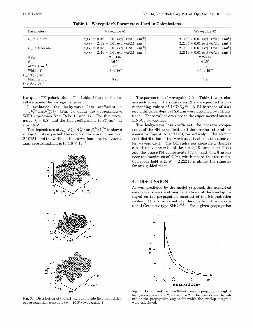
has quasi-TM polarization. The fields of these modes os-cillate inside the waveguide layer.I evaluated the leaky-wave loss coefficient a
5 2ko2v Im@NTE
2v(u)# (Fig. 4), using the approximativeWKB expression from Refs. 16 and 17. For this wave-guide uc 5 9.8° and the loss coefficient is to 37 cm21 atu 5 16.5°.The dependence of IGR(b G
v , b R2v) on b R
2v/k o2v is shown
in Fig. 5. As expected, the integral has a maximum near2.19154, and the width of this curve, found by the Lorent-zian approximation, is to 4.6 3 1024.
Fig. 3. Distribution of the SH radiation mode field with differ-ent propagation constants (u 5 16.5°) (waveguide 1).
The parameters of waveguide 2 (see Table 1) were cho-sen as follows: The substrate’s RI’s are equal to the cor-responding values of LiNbO3.
24 A RI increase of 0.01and a diffusion depth of 2.6 mm were assumed by calcula-tions. These values are close to the experimental ones inLiNbO3 waveguides.The leaky-wave loss coefficient, the nonzero compo-
nents of the SH wave field, and the overlap integral areshown in Figs. 4, 6, and 5(b), respectively. The electricfield distribution of the wave at v is almost the same asfor waveguide 1. The SH radiation mode field changesconsiderably: the ratio of the quasi-TE component Ey(x)and the quasi-TM components [Ex(x) and Ez(x)] growsnear the maximum of Ey(x), which means that the radia-tion mode field with N 5 2.22211 is almost the same asfor any guided mode.
4. DISCUSSIONAs was predicted by the model proposed, the numericalsimulation shows a strong dependence of the overlap in-tegral on the propagation constant of the SH radiationmodes. This is an essential difference from the conven-tional Cerenkov-type SHG.10,11 For a given propagation
Fig. 4. Leaky-mode loss coefficient a versus propagation angle ufor 1, waveguide 1 and 2, waveguide 2. The points show the val-ues at the propagation angles for which the overlap integralswere calculated.
336 J. Opt. Soc. Am. B/Vol. 14, No. 2 /February 1997 D. V. Petrov
direction the range of bR2v where the overlap integral is
large depends on the leaky-wave loss coefficient. In fact,the difference in the widths of the curves in Figs. 5(a) and5(b) is ;1 order of magnitude. As shown in Fig. 4, a forwaveguide 1 (37 cm21) is ;20 times larger than for wave-guide 2 (1.7 cm21).The overlap integral in waveguide 2, where the leaky-
wave loss coefficient is small, depends strongly on thepropagation constant. Consequently we can consider themaximal value of this integral as the value of the overlapintegral in the guided–guided interaction. (In guided–guided SHG this dependence is described by the d func-tion.) The maximum value of the overlap integral is;1 order of magnitude less in waveguide 1 than in wave-guide 2. Nevertheless, it is much larger than the overlapintegral for radiation modes with propagation constantsother than that of the leaky wave. (For example, inwaveguide 1 the overlap integral is 0.09 for the radiationmode with N 5 2.1935, whereas the maximum value ofthe overlap integral is 0.78; i.e., the value of the overlapintegral decreases approximately eight times by detuningof ;DN 5 0.002. For the same detuning in waveguide 2the reduction is ;15 times.)Cerenkov-type SHG efficiency strongly depends on the
choice of optical parameters (diffusion depth and maxi-mum value of the refractive index in the waveguide; see,for example, Refs. 10 and 11). The proper choice of theseparameters can satisfy the wave-vector-matching condi-tion by u ' uc with a large value of the overlap integral.In this case the width of the overlap function should in-
Fig. 5. (a) Overlap integral versus propagation constant of theSH radiation mode. (b) Overlap integral for waveguide 2 shownon a different scale. Dotted curves represent the Lorentzian ap-proximation.
crease, but the SHG efficiency is still comparable with theguided–guided SHG efficiency. The wave-vector-matching condition will not be so strictly important formaintaining high efficiency because the width of the over-lap integral function is broad.Consider now the angular spectrum of the radiation
modes. Even without calculation of the final integral[Eq. (6)] one can see that the angular distribution of theradiation field E2v(x, z, t, L) is determined by L and bythe relative position of the maximum of IGR(b G
v , b R2v)
and the maximum of sin c2@(bR2v 2 2bG
v)L/2#. If the peaksof these two functions of bR
2v are not coincident (bR2v
5 2bGv Þ bLW
2v ), for small L the radiation modes with bR2v
in the vicinity of bLW2v provide the main contribution to the
total radiation field at 2v. The main lobe of the radiationfield is directed into the substrate under the angle u*5 arccos@bLW
2v /(ko2vno
2v)# (Fig. 7). However, as L in-creases, the half-width of the function sin c2@(bR
2v
2 2bGv)L/2# becomes narrow, and the radiation modes
with bR2v in the vicinity of the phase-matching point 2bG
v
provide the main contribution to the total radiation fieldat 2v. The SH wave radiates into the substrate mainlyunder the angle urad (see Fig. 7). Obviously this shiftdoes not occur when the peaks of the two above-
Fig. 6. Distribution of the SH radiation mode field with differ-ent propagation constants (u 5 61.5°) (waveguide 2).
D. V. Petrov Vol. 14, No. 2 /February 1997 /J. Opt. Soc. Am. B 337
Fig. 7. Radiation of the SH wave into the substrate for (a)DbL ! 1 and (b) DbL @ 1. Db 5 (bR
2v 2 2bGv ). The solid ar-
rows are the double wave vector at v; the dashed arrows are thewavevector of the SH wave.
Fig. 8. Product f(bR2v) 5 IGR(b G
v , b R2v) 3 sin c2@(bR
2v 2 2bGv)
3 L/2] as a function of bR2v for different interaction lengths
L: (a) 2bGv Þ bLW
2v , (b) 2bGv 5 bLW
2v .
mentioned functions are coincident. Hence the overlapintegral IGR(b G
v , b R2v) is responsible in our case for the
efficiency of the SHG as well as for the angular distribu-tion of the radiating SH field. In conventional Cerenkov-type SHG in the waveguide2,10 the main lobe of the radi-ating field distribution becomes narrow with increasinginteraction length, but it does not change its direction.The product sin c2@(bR
2v 2 2bGv)L/2#IGR(b G
v , bR2v) as a
function of the propagation constants of the SH radiationmode is shown in Fig. 8 for different interaction lengths.As this figure shows, if the wave-vector-matching condi-tion is not satisfied (2bG
v Þ bLW2v ) the radiation field with
propagation constant bLW2v radiates into the substrate for
small interaction lengths @(bR2v 2 2bG
v )L ! 1#. As (bR2v
2 2bGv )L @ 1, the SH radiation field has the propagation
constant 2bGv . In an intermediate range of the interac-
tion lengths the radiation field can form two or morebeams. If 2bG
v 5 bLW2v [Fig. 8(b)] the radiation field has
the propagation constant 2bGv for any interaction length.
5. CONCLUSIONSecond harmonic generation in an anisotropic opticalwaveguide has new features if leaky waves are involvedin the interaction. In particular, Cerenkov-type SHG ef-ficiency can be comparable with the SHG efficiency of twoguided modes, and it can be observed without critical con-trol of the phase-matching condition. The direction ofthe main lobe of the Cerenkov radiation field distributiondepends on the interaction length and the initial choice ofthe propagation direction. These results can be used inthe construction of short-wavelength light sources, gen-eration of ultrashort second-harmonic pulses, and studyof x(2):x(2) cascading process.
ACKNOWLEDGMENTThis research was supported by the Brazilian AgencyConselho Nacional de Desenvolvimento Cientıfıco e Tech-nologico.Permanent address, The Institute of Semiconductor
Physics, 630090, Novosibirsk, Russia; current address,Department of Signal Theory and Communications, Uni-versitat Politecnica de Catalunya, UPC-D3, 08034, Barce-lona, Spain.
REFERENCES1. G. I. Stegeman and R. H. Stolen, ‘‘Waveguides and fibers for
nonlinear optics,’’ J. Opt. Soc. Am. B 6, 652–662 (1989).2. A. Yariv, ‘‘Coupled-mode theory for guided-wave optics,’’
IEEE J. Quantum Electron. QE-9, 919–930 (1973).3. Y. Suematsu, Y. Sasaki, K. Furuya, K. Shibata, and S.
Ibukuro, ‘‘Optical second-harmonic generation due toguided-wave structure consisting of quartz and glass film,’’IEEE J. Quantum Electron. QE-10, 222–229 (1974).
4. E. M. Zolotov, V. M. Pelekhatyi, A. M. Prokhorov, and V. A.Chernikh, ‘‘Investigation of second-harmonic generation indiffused LiNbO3 waveguides,’’ Sov. Phys. JETP 49, 603–607 (1979).
5. W. Sohler and H. Suche, ‘‘Second harmonic generation inTi:diffused LiNbO3 optical waveguides with 25% conversionefficiency,’’ Appl. Phys. Lett. 33, 518–520 (1978).
6. P. K. Tien, R. Ulrich, and R. J. Martin, ‘‘Optical second har-monic generation in form of coherent Cerenkov radiation
338 J. Opt. Soc. Am. B/Vol. 14, No. 2 /February 1997 D. V. Petrov
from a thin-film waveguide,’’ Appl. Phys. Lett. 17, 447–450(1970).
7. N. A. Sanford and J. M. Connors, ‘‘Optimization of the Cer-enkov sum-frequency generation in proton-exchangedMg:LiNbO3 channel waveguides,’’ J. Appl. Phys. 65, 1429–1437 (1989).
8. M. J. Li, M. de Micheli, Q. He, and D. B. Ostrovsky, ‘‘Cer-enkov configuration second harmonic generation in proton-exchanged lithium niobate guides,’’ IEEE J. Quantum Elec-tron. 26, 1384–1393 (1990).
9. C. J. van der Poel, J. D. Bierlein, J. B. Brown, and S. Golak,‘‘Efficient type I blue second harmonic generation in peri-odically segmented KTiOPO4 waveguides,’’ Appl. Phys.Lett. 57, 2074–2076 (1990).
10. H. Tamada, ‘‘Coupled-mode analysis of second harmonicgeneration in the form of Cerenkov radiation from a planaroptical waveguide,’’ IEEE J. Quantum Electron. 27, 502–508 (1991).
11. N. Hashizume, T. Kondo, T. Onda, U. Ogasawara, S.Umegaki, and R. Ito, ‘‘Theoretical analysis of Cerenkov-type optical second-harmonic generation in slabwaveguides,’’ IEEE J. Quantum Electron. 28, 1798–1813(1992).
12. G. W. Wang and E. Garmire, ‘‘Generation of ultrashortsecond-harmonic pulses by compressing the Cerenkov out-put,’’ Opt. Lett. 20, 264–266 (1995).
13. G. J. M. Krijnen, G. I. Stegeman, and H. J. W. M. Hoekstra,‘‘High-contrast all-optical switching by using cascading inthe Cerenkov regime,’’ in Conference on Lasers and Electro-Optics, Vol. 15 of 1995 OSA Technical Digest Series (Opti-cal Society of America, Washington, D.C., 1995), p. 265.
14. K. Yamanouchi, T. Kamiya, and K. Shibayama, ‘‘New leakysurface waves in anisotropic metal-diffused opticalwaveguides,’’ IEEE Trans. Microwave Theory Tech. MTT-26, 298–305 (1978).
15. S. K. Sheem, W. K. Burns, and A. F. Milton, ‘‘Leaky-wavepropagation in Ti-diffused LiNbO3 and LiTaO3waveguides,’’ Opt. Lett. 3, 76–78 (1978).
16. W. K. Burns, S. K. Sheem, and A. F. Milton, ‘‘Approximatecalculation of leaky mode loss coefficients for Ti-diffused
LiNbO3-waveguides,’’ IEEE J. Quantum Electron. QE-15,1282–1289 (1979).
17. J. Ctyroky and M. Cada, ‘‘Generalized WKB method for theanalysis of light propagation in inhomogeneous anisotropicoptical waveguides,’’ IEEE J. Quantum Electron. QE-17,1064–1070 (1981).
18. E. A. Kolosovski, D. V. Petrov, A. V. Tsarev, and I. B. Yak-ovkin, ‘‘An exact method for analyzing light propagation inanisotropic inhomogeneous optical waveguide,’’ Opt. Com-mun. 43, 21–25 (1982).
19. E. A. Kolosovski, D. V. Petrov, and I. B. Yakovkin, ‘‘Spatialspectrum of leaky waves generated by scattering of aguided wave from an acoustic wave,’’ Opt. Commun. 60,280–286 (1986).
20. L. Torner, F. Canal, and J. Hernandez-Marco, ‘‘Leakymodes in multilayer uniaxial optical waveguides,’’ Appl.Opt. 29, 2805–2813 (1990).
21. L. Torner, J. Recolons, and J. P. Torre, ‘‘Guided-to leakymode transition in uniaxial optical slab waveguide,’’ J.Lightwave Technol. 11, 1592–1600 (1992).
22. A. D’Orazio, M. De Sario, V. Petruzzelli, and F. Pruden-zano, ‘‘Leaky wave propagation in planar multilayer bire-fringent waveguides: longitudinal dielectric tensor con-figuration,’’ J. Lightwave Technol. 12, 453–462 (1993).
23. D. S. Smith, H. D. Riccius, and R. P. Edwin, ‘‘Refractive in-dices of lithium niobate,’’ Opt. Commun. 17, 332–335(1976).
24. D. Marcuse, Theory of Dielectric Waveguides (Academic,New York, 1974).
25. S. Yamamoto and Y. Okamura, ‘‘Guided-radiation mode in-teraction in off-axis propagation in anisotropic opticalwaveguides with applications to direct-intensity modula-tion,’’ J. Appl. Phys. 50, 2555–2564 (1979).
26. L. D. Landau and E. M. Lifshitz, Quantum Mechanics:Nonrelativistic Theory (Pergamon, Oxford, 1977), p. 63.
27. E. A. Kolosovski, D. V. Petrov, and A. V. Tzarev, ‘‘Fre-quency dependence of the acoustooptical interaction effi-ciency of TE-modes in a diffused optical waveguide,’’ Sov. J.Quantum Electron. 9, 1119–1122 (1979).