11119271 (1) – APRIL 2018 SECTION 02351 - 1 EXCAVATION, BACKFILL, AND TRENCHING SECTION 02351 EXCAVATION, BACKFILL, AND TRENCHING PART 1 GENERAL 1.1 DESCRIPTION A. Work Specified. 1. The CONTRACTOR shall furnish all labor, materials, equipment, and incidentals necessary for excavation, trenching, backfill, and compaction as shown and specified. Disposal of excess and unsuitable excavated material is included. 2. Backfill of excavations with acceptable materials as specified in other Sections. B. Related Work Specified Elsewhere. 1. Section 02316 - Select Granular Materials. 2. Section 02480 – Landscaping and Restoration. 3. Section 15051 - Buried Piping Installation. 1.2 QUALITY ASSURANCE A. Reference Standards 1. ASTM A36, Structural Steel. 2. ASTM A328, Steel Sheet Piling. 3. ASTM D422, Particle-Size Analysis of Soils. 4. ASTM D698, Moisture-Density Relations of Soils, using 5.5-pound Rammer and 12-inch Drop. 5. ASTM D1556, Density of Soil in Place by the Sand-Cone Method. 6. ASTM D1557, Moisture-Density Relations of Soils, using 10-pound Rammer and 18-inch Drop. 7. ASTM D2321, Recommended Practices for Underground Installation of Pipe for Sewers and Other Gravity Flow Applications. 8. ASTM D6938, Density of Soil and Soil-Aggregate in Place by Nuclear Method (Shallow Depth). 9. AISC Specifications for the Design, Fabrication and Erection of Structural Steel for Buildings. 10. Occupational Safety and Health Administration (OSHA) Regulations. 11. Industrial Code Rule 23.
Transcript
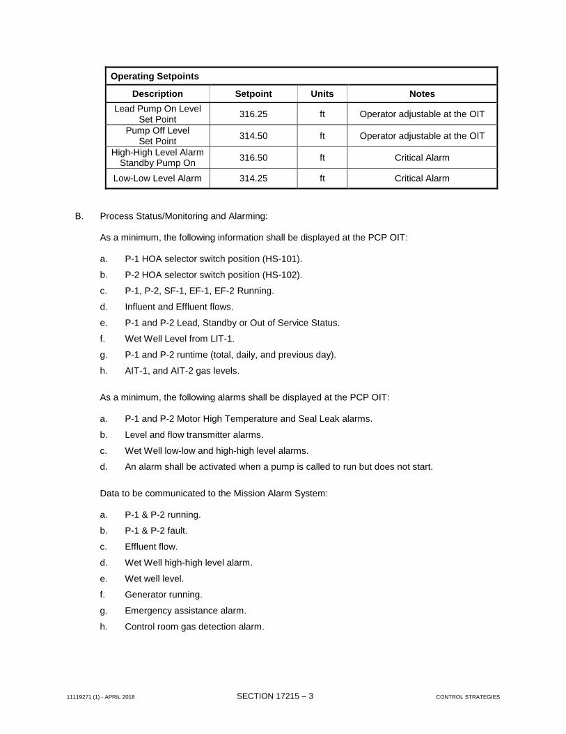
11119271 (1) – APRIL 2018 SECTION 02351 - 1 EXCAVATION, BACKFILL, AND TRENCHING
SECTION 02351
EXCAVATION, BACKFILL, AND TRENCHING PART 1 GENERAL 1.1 DESCRIPTION
A. Work Specified.
1. The CONTRACTOR shall furnish all labor, materials, equipment, and incidentals necessary
for excavation, trenching, backfill, and compaction as shown and specified. Disposal of excess and unsuitable excavated material is included.
2. Backfill of excavations with acceptable materials as specified in other Sections.
4. ASTM D698, Moisture-Density Relations of Soils, using 5.5-pound Rammer and 12-inch Drop.
5. ASTM D1556, Density of Soil in Place by the Sand-Cone Method.
6. ASTM D1557, Moisture-Density Relations of Soils, using 10-pound Rammer and 18-inch Drop.
7. ASTM D2321, Recommended Practices for Underground Installation of Pipe for Sewers and Other Gravity Flow Applications.
8. ASTM D6938, Density of Soil and Soil-Aggregate in Place by Nuclear Method (Shallow Depth).
9. AISC Specifications for the Design, Fabrication and Erection of Structural Steel for Buildings.
10. Occupational Safety and Health Administration (OSHA) Regulations.
11. Industrial Code Rule 23.
11119271 (1) – APRIL 2018 SECTION 02351 - 2 EXCAVATION, BACKFILL, AND TRENCHING
1.3 SUBMITTALS
A. Before any excavation begins, the CONTRACTOR shall obtain all permits and licenses required
by governing authorities having jurisdiction and submit certified copies to ENGINEER prior to work being performed.
B. The CONTRACTOR shall submit drawings submitted with a PE stamp, for information only, for
the following items as required:
1. Sheeting, shoring and bracing.
2. Dewatering systems.
3. Cofferdams.
4. Additional protection systems required.
5. Underpinning.
6. Underdraining.
7. Sediment and Erosion control.
8. Boring and Receiving Pits.
C. The CONTRACTOR shall submit proposed materials, methods and operations of backfilling and compaction to the ENGINEER for review prior to the start of work. A list of equipment to be used in CONTRACTOR’s methods and operations must be included.
D. All drawings shall be prepared and sealed by an independent professional engineer recognized as
an expert in the specialty involved and licensed to practice in the State of Rhode Island. The drawings shall be submitted to the ENGINEER to establish compliance with the terms of the Contract Documents. Calculations shall not be submitted. Drawing submissions will not be checked and will not imply approval by the ENGINEER of the work involved. CONTRACTOR shall be wholly responsible for designing, installing, and operating whatever system is necessary to accomplish satisfactory sheeting, bracing, protection, underpinning, and dewatering.
PART 2 PRODUCTS 2.1 MATERIALS
A. Bedding and Select Backfill.
1. Bedding and select backfill material shall be in accordance with Section 02316 - Select Granular Materials.
B. Backfill and Fill Materials.
1. Excavated materials may be used for backfill provided:
a. Material is sandy, loamy or similar to bank run gravel.
b. Material is free of debris, hazardous materials, frozen materials, organic or other deleterious materials. Material greater than 4 inches in any direction is unacceptable. Material greater than 2 inches in any direction is unacceptable for backfill directly against the watermain.
11119271 (1) – APRIL 2018 SECTION 02351 - 3 EXCAVATION, BACKFILL, AND TRENCHING
c. Maximum dry density and optimum moisture content are determined in accordance
with the above.
d. Material is reviewed and deemed acceptable by the ENGINEER.
2. Use select granular backfill within 5 feet or within a 1 on 1 slope from the trench to the edge of pavement of all roadways.
C. Topsoil.
1. Topsoil shall be furnished and installed and coordinated with Section 02480, Landscaping and Restoration.
D. Explosives.
1. Explosives are allowed under approval by the Engineer, Owner, and Town..
E. Sheeting, Shoring and Bracing.
1. Used material shall be in good condition, not damaged or excessively pitted. Unless otherwise specified, all sheeting to remain in place shall be new. New or used sheeting may be used for temporary work.
2. All timber used for breast boards (lagging) shall be new or used, meeting the requirements
for Douglas Fir Dense Construction grade or Southern Pine No. 2 Dense S3. Where close or tight sheeting is required, wood sheeting shall be tongued and grooved.
3. All steel work for sheeting, shoring, bracing, cofferdams, etc. shall be designed in
accordance with the provisions of the "Specifications for the Design, Fabrication and Erection of Structural Steel for Buildings," of the AISC except that field welding will be permitted.
4. Steel sheet piling shall be manufactured from steel conforming to ASTM A328. Steel
soldier piles, wales and braces shall be new or used and shall conform to ASTM A36. 5. Steel sheeting shall have a minimum thickness of 3/8-inch in web, unless otherwise
specified. PART 3 EXECUTION
3.1 INSPECTION
A. The CONTRACTOR shall provide the ENGINEER with sufficient time and means to examine the areas and conditions under which excavating, filling and grading are to be performed. The CONTRACTOR shall notify the ENGINEER of conditions detrimental to the proper and timely completion of work. The CONTRACTOR shall not proceed with work until unsatisfactory conditions have been corrected in a manner acceptable to the ENGINEER.
3.2 TEST PITS
A. Where shown or ordered by the ENGINEER, the CONTRACTOR shall excavate and backfill test pits in advance of construction to determine conditions or location of existing facilities. The CONTRACTOR shall perform all work required in connection with excavating, stockpiling, maintaining, sheeting, shoring, backfilling and restoring the surface for the test pits.
11119271 (1) – APRIL 2018 SECTION 02351 - 4 EXCAVATION, BACKFILL, AND TRENCHING
B. Test pits which the CONTRACTOR excavates that are not shown on the Drawings or specified or ordered shall be at the CONTRACTOR’s expense.
C. No test pits will be dug prior to utility company stakeout.
D. Asphalt patch for temporary repair shall be placed as directed by the ENGINEER. 3.3 EROSION CONTROL
A. All necessary precautions shall be taken to preclude the contamination of any wetland or waterway by suspended solids, sediment, fuels, solvents, lubricants, epoxy coatings, paints, concrete leachate or any other environmentally deleterious substance associated with the Project.
B. All necessary precautions shall be taken to prevent the entry of raw concrete or concrete liquors into the waters and/or wetlands of the State of Rhode Island. Equipment washwater from this Project shall not be allowed to enter any waterway or wetland.
C. All sediments are to be retained on the Project Site through the use of hay bales, silt fences or other barriers, as specified or approved by the local authority having jurisdiction, to prevent erosion.
D. All areas of soil disturbance resulting from this Project shall be seeded with an appropriate perennial grass seed and mulched with hay or straw within one week of final grading. Mulch shall be maintained until a suitable vegetative cover has been established.
E. Pumped groundwater collected from excavations shall not be allowed to be discharged directly to any wetland, waterway, or other water body.
F. Contamination of any wetland, waterway, or other water body shall be cleaned and/or restored to the satisfaction of the ENGINEER and governing authorities at the expense of the CONTRACTOR.
3.4 EXCAVATION
A. The CONTRACTOR shall perform all excavation required to complete the work as shown and specified. Excavations shall include earth, sand, clay, gravel, hardpan, boulders and ledge rock, decomposed rock, pavements, rubbish and all other materials within the excavation limits, except rock. Where the excavation is in rock meeting the definition of rock excavation in this Section (requiring drilling, jack-hammering and hand removal), the rock shall be removed as specified in this Section.
B. Excavations for pipelines, utilities and structures shall be open excavations, shored and braced
where necessary, according to OSHA standards, to prevent possible injury to workmen and to new and existing structures or pipelines.
C. Where the pipeline, utility or structure is to be placed below the ground water table, well-points, cofferdams or other acceptable methods shall be used to permit construction under dry conditions. Dry conditions shall prevail until concrete has reached sufficient strength to withstand earth and hydrostatic loads and until the pipelines are properly jointed, tested and backfilled.
D. Pumping in excavations shall be done in such a manner so as to prevent damage to the existing subgrade, and to prevent the carrying away of unsolidified concrete materials.
E. Excavations for pipelines shall be made sufficiently wide to permit proper laying and jointing of the pipe. The trench width at the top of the pipe should not be greater than the outside diameter of
11119271 (1) – APRIL 2018 SECTION 02351 - 5 EXCAVATION, BACKFILL, AND TRENCHING
the pipe barrel plus 2 feet, but shall be sufficient to allow thorough compacting of earth refill adjacent to the bottom half of the pipe. The depth of trench shall be sufficient to allow a minimum cover over the top of the pipe as shown on the drawings. The use of excavating equipment which requires the trench to be excavated to an excessive width will not be allowed. All trenches for buried piping shall be excavated at least 6 inches below the bottom of the pipe and backfilled with pipe bedding material as specified in Section 02316 – Select Granular Materials.
F. Acceptable excavated materials shall be stockpiled in specified areas until required for backfill or fill. Place, grade and shape stockpiles for proper drainage.
1. Locate and retain soil materials away from edge of excavations.
2. Unsuitable backfill material shall be kept separate from all other material and shall be disposed of as specified hereinafter. Disposal of unsuitable and excess excavated material shall be accomplished immediately upon removal from the excavation.
3. Stockpiles shall not be located such that they interfere with traffic or access to public or private property. If necessary, the CONTRACTOR shall maintain additional stockpile areas located elsewhere on the Site, and shall transport the suitable backfill material to and from such stockpile areas as required for the work.
4. In built-up districts and in streets where traffic conditions render it necessary, the material excavated from the initial opening shall be removed by the CONTRACTOR as soon as excavated, and the material subsequently excavated, if suitable for the purpose, shall be used to backfill the trenches in which pipe has been laid or structures have been built, and neither the excavated material nor materials of construction shall be stored on the streets or sidewalks.
G. If the material at the design grade is unsuitable as determined by the ENGINEER, the CONTRACTOR, when ordered in writing, shall excavate additional material to the depth necessary and shall backfill to the proposed grade with select granular material.
H. Unless otherwise directed or permitted, not more than 100 feet of trench in advance of the end of the completed pipe or structure therein shall be opened at any time. Every trench in rock shall be fully opened at least 30 feet in advance of any place where masonry or pipe is being laid. Any time when the CONTRACTOR’s crews are not on the job working, a trench length equal to or less than one-half of the last length of pipe installed may be left open, but properly covered or barricaded to protect the public.
I. At such locations where two pipes may be installed in parallel in a common trench, and where specified, the CONTRACTOR shall install the pipes a minimum of 2 feet apart as measured horizontally from the outside diameter of pipe.
3.5 UNAUTHORIZED EXCAVATION
A. All excavation outside the lines and grades shown and not specified, together with the removal and disposal of the associated material shall be at the CONTRACTOR’s expense. The unauthorized excavation shall be filled as directed by the ENGINEER with select compacted backfill at the CONTRACTOR’s expense. Claims and damages resulting from the CONTRACTOR’s unauthorized excavation will be his sole responsibility.
11119271 (1) – APRIL 2018 SECTION 02351 - 6 EXCAVATION, BACKFILL, AND TRENCHING
3.6 DRAINAGE AND DEWATERING
A. General
1. Prevent surface and subsurface water from flowing into excavations and from flooding adjacent areas.
2. Remove water from excavation as fast as it collects.
3. Maintain the ground water level at least 2 feet below the bottom of the excavation to provide a stable surface for construction operations and to prevent damage to the work during all stages of construction.
4. Provide and maintain pumps, sumps, suction and discharge lines and other dewatering system components necessary to convey water away from excavations.
5. Provide sediment traps when water is conveyed into water courses.
6. Notify the ENGINEER before shutting down dewatering systems for any reason.
7. Standing water shall not be permitted in the excavation at any time. If the material at the design grade becomes unsuitable or contaminated due to the actions of the CONTRACTOR, the CONTRACTOR shall excavate additional material to the depth necessary and shall backfill to the proposed grade with select fill or crushed stone.
8. 100 percent stand-by pumps (gasoline powered) shall be maintained at the Site at all times.
9. Any hardships created by the temporary dewatering for this Contract which adversely affects the water supply to local property owners, shall be satisfactorily resolved by the CONTRACTOR, including the provision of temporary water service, if required, at no additional cost to the OWNER.
10. Obtain required permits from agencies of jurisdiction, state DEC, and USACOE, for any water being discharged into rivers, streams, or water courses.
B. Disposal of Water Removed by Dewatering Systems
1. Dispose of all water removed from the excavation in such a manner as not to endanger public health, property, or any portion of the work under construction or completed.
2. Dispose of water in such a manner as to cause no inconvenience to the OWNER or others on or adjacent to the Site.
3. Convey water from the excavation in a closed conduit. Do not use trench excavations as temporary drainage ditches.
4. Disposal of water shall be by specified methods and shall not cause erosion or sedimentation to occur in existing drainage systems. All sedimentation or blocking of existing systems shall be thoroughly cleaned and returned to original condition by the CONTRACTOR at his expense.
5. Damage caused by the CONTRACTOR’s operations to public or private property shall be repaired by him to the satisfaction of the ENGINEER and the damaged property owner at the CONTRACTOR’s expense.
11119271 (1) – APRIL 2018 SECTION 02351 - 7 EXCAVATION, BACKFILL, AND TRENCHING
6. The CONTRACTOR shall perform all work, furnish all materials and install all measures required to reasonably control soil erosion resulting from construction operations and prevent excessive flow of sediment from the construction Site. Such work may include the installation of water diversion structures, diversion ditches and sediment basins and seeding, mulching or sodding critical areas to provide temporary protection. The CONTRACTOR shall submit a plan showing the methods to be used for controlling erosion and sedimentation during construction along with the schedule of construction operations to the ENGINEER for review.
7. All erosion and sediment control practices shall be in place prior to any grading operations and installation of proposed structures or utilities.
8. All erosion and sediment control practices shall be left in place until construction is completed and/or area is stabilized.
9. Where necessary, disturbed areas shall be temporarily seeded and\or mulched until proper weather conditions exist for establishment of a permanent vegetative cover.
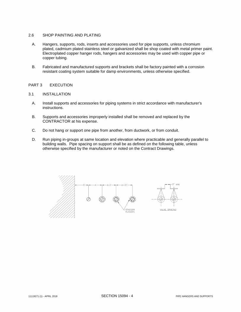
3.7 SHEETING, SHORING, AND BRACING
A. General
1. Unless otherwise shown or specified, excavations shall be open, shored and braced or sheeted where necessary to prevent injury to workmen, structures, pipelines and utilities.
2. Structures within 100 feet of sheeting installations shall be subject to a pre-construction survey to identify and record existing structural conditions. In the instance of private residencies, the homeowners shall be contacted directly. These inspections shall be carried out by a pre-inspection firm experienced in this line of work.
3. During the actual construction process, the CONTRACTOR shall provide the monitoring and recording of the actual vibrations generated. A baseline of ambient vibration levels shall be established prior to driving sheet piling.
a. The particle acceleration during the driving of the sheet piling shall not exceed 2.0 FPS.
b. The CONTRACTOR will be required to change the construction methods if the work is resulting in unacceptable vibration levels.
4. All municipal, county, state, and federal ordinances, codes, regulations, and laws shall be observed. The CONTRACTOR shall provide all sheeting, shoring, and bracing which conforms local and state DOL requirements and all applicable sections of the 1970 Occupational Safety and Health Act (OSHA), and any other requirements as necessary.
5. All municipal, county, state and federal ordinances, codes, regulations, laws and OSHA regulations shall be observed.
6. Maintain shoring and bracing in excavations regardless of time period excavations will be open. Carry down the shoring and bracing as excavation progresses.
7. Safe and satisfactory sheeting, shoring and bracing shall be the entire responsibility of the CONTRACTOR.
11119271 (1) – APRIL 2018 SECTION 02351 - 8 EXCAVATION, BACKFILL, AND TRENCHING
8. The CONTRACTOR shall be held accountable and responsible for the sufficiency of all shoring and bracing used and for all damage to persons or property resulting from the improper quality, strength, placing, maintaining or removing of the same.
9. The ENGINEER’s permission to proceed with work in either a sheeted, shored braced or open trench condition shall in no way relieve the CONTRACTOR from the above responsibilities.
10. The clearances and types of temporary structures, insofar as they affect the character of the finished work, and the design of steel sheeting to be left in place, will be subject to the review of the ENGINEER, but the CONTRACTOR shall be solely responsible for the adequacy of all sheeting, shoring, bracing, cofferdamming, etc.
11. Unless otherwise shown, specified, or ordered, all materials used for temporary construction shall be removed when work is completed. Such removal shall be made in a manner not injurious to the pipelines or structures.
12. All steel sheet piling designed to remain in place shall be new materials. New or used materials may be used for temporary work.
13. Steel sheet piling shall be manufactured from steel conforming to ASTM A328. Steel for soldier piles, wales, and braces shall be manufactured to conform to ASTM A36.
B. Sheeting Left in Place
1. Steel sheet piling shall be left in place or where conditions are such that the removal of sheeting will endanger the work or adjacent pipes or structures or when ordered in writing to be left in place by the ENGINEER. It shall consist of rolled sections of the continuous interlocking type unless otherwise specified. The type and design of the sheeting and bracing shall conform to the above specifications for all steel work for sheeting and bracing.
2. Steel sheet piling to be left in place shall be driven straight to the lines and grades as shown or directed. The piles shall penetrate into firm materials with secure interlocking throughout the entire length of the pile. Damaged piling having faulty alignment shall be pulled and replaced by new piling.
3. The type of guide structure used and method of driving for steel sheet piling to be left in place shall be submitted to the ENGINEER for review. Jetting will not be permitted.
4. The CONTRACTOR shall cut off piling left in place at least 2 feet below road surface or to the grades shown or ordered by the ENGINEER and shall dispose of the cutoffs.
5. Portions of sheeting or soldier piles and breast boards which are in contact with concrete shall be left in place.
C. Removal of Sheeting and Bracing
1. Sheeting and bracing shall be removed from excavation unless otherwise indicated by the ENGINEER. Removal shall be done so as to not cause injury to the work.
a. Wood or steel sheeting shall not be removed when adjacent to structures, pavement, pipes, or any other public or private property where removal may cause damage to such property.
b. Fill all voids left by removal of sheeting with select fill.
11119271 (1) – APRIL 2018 SECTION 02351 - 9 EXCAVATION, BACKFILL, AND TRENCHING
2. Removal of sheet piling shall be done so as not to cause injury to the Work. Removal shall be equal on both sides of excavation to ensure no unequal loads on pipe or structures.
D. Pipeline Alignment shall be in accordance with all requirements of the RIDOT with regard to installation in and around existing Right-of-Ways and easements.
E. In areas where the Drawings call for sheeting to remain in place, alternate sheeting methods will not be allowed. Only pre-driven, steel sheet piling systems designed for the CONTRACTOR by a professional engineer will be allowed in these areas.
3.8 BACKFILL AND COMPACTION
A. All backfill required for trenches and structures required to provide the finished grades shown and as described herein shall be furnished, placed and compacted in 6-inch lifts by the CONTRACTOR. Unless otherwise specified or required, fill shall be obtained from the excavated materials. All materials used for filling and backfilling shall be soil of acceptable quality, free from boulders, frozen lumps, wood, stumps, sludge, or other organic matter or other deleterious or hazardous materials. Excavated materials meeting these requirements and approved by the ENGINEER may be used as backfill.
B. Rock and/or earth material may be encountered during the work that is unsuitable for backfilling. When this material is encountered, it shall be stockpiled at OWNER’s specified location within OWNER’s facility. In this event, the CONTRACTOR shall be responsible for furnishing, delivering and installing clean earth or select backfill materials to properly and completely backfill the excavation. Backfill material for these situations may be obtained from other areas of the Project where suitable material is available or from off-Site locations as approved by the ENGINEER. All backfill material is subject to the ENGINEER’s review and must meet the minimum requirements of the specifications above.
C. Backfill excavations as promptly as work permits, but not until completion of the following:
1. Inspection by the ENGINEER of all work within the excavation.
2. Inspection, testing approval, and recording of locations of underground utilities, connections, branches, structures and other facilities.
3. Removal of shoring and bracing, and backfilling of voids with satisfactory materials. Cut off temporary sheet piling driven below bottom of structures and remove in a manner to prevent settlement of the structure or utilities, or leave in place if required.
4. Removal and proper disposal of trash and debris.
D. Excavation shall be kept dry during backfilling operations. Backfill around piping and structures shall be brought up evenly on all sides.
E. The minimum density to be obtained during backfilling operations shall be 95 percent and is a percentage of the maximum density obtained in the laboratory as defined in ASTM D698 Method C including Note 2. This percentage is of modified Proctor density. In-place density determinations shall be made using a sand density cone or equivalent method as specified by ASTM D1556. If any bricks, bottles, pieces of metal, debris or other foreign matter larger than 3/4-inch size are encountered in the density test hole, a different test location shall be chosen. The ENGINEER will determine the frequency of field testing required to determine the density of the fill and shall direct the number and location of density tests. All equipment necessary to determine fill density, including nuclear density meters, shall be supplied by the CONTRACTOR.
11119271 (1) – APRIL 2018 SECTION 02351 - 10 EXCAVATION, BACKFILL, AND TRENCHING
F. The water content of fill material shall be controlled during placement within the range necessary to obtain the density specified. In general, the moisture content of the fill shall be within 5 percent dry and 2 percent wet of the optimum moisture content for the specified density as determined by laboratory tests. The CONTRACTOR shall perform all necessary work to adjust the water content of the material to within the range necessary to permit the density specified. No fill material shall be placed and no compaction of fill will be permitted when there is any standing water in the trenches or when the fill material or the ground the fill is to be placed on is frozen.
G. The CONTRACTOR is not allowed to access any part of an existing water supply system (fire hydrants, etc.) as a source of water for any reason during construction activities, including the use of water for backfilling to obtain the proper moisture content.
H. If the specified densities are not obtained because of the CONTRACTOR’s improper control of placement or compaction procedures, or because of inadequate or improperly functioning equipment, the CONTRACTOR shall perform whatever work is required to provide the specified densities. This work shall include complete removal of unacceptable fill areas, replacement and recompaction until acceptable fill is provided.
I. All backfill in pipe trenches shall be placed in horizontal layers not exceeding 6 inches in depth and thoroughly compacted before the next layer is placed.
J. Where pipe is laid in rock excavation, crushed stone or gravel fill shall be carefully placed and tamped over the rock before the pipe is laid. After laying pipe, the balance of the backfill shall be placed as described herein above.
K. Placement:
1. Place pipe bedding, select backfill and/or earth backfill or borrow materials, as specified herein and in Section 15051- Buried Piping Installation.
2. Trenches under roadways shall be backfilled with select backfill material for the entire length of the open cut crossing plus 5 feet back from the edge of pavement or a distance equal to a 1 on 1 slope to the invert, whichever is greater.
3. Where shoulders are excavated, the trench shall be backfilled with select granular material.
4. The entire trench area under driveways, parking areas, and sidewalks, shall be backfilled with select granular material in accordance with the Contract Drawings and Specifications.
5. Prior to commencing with the backfilling operation, the CONTRACTOR shall submit information to the ENGINEER such as catalog cuts, specification sheets, etc., describing the type of compaction equipment he intends to use.
L. Pipe Trench Preparation
1. Braced trench width shall be minimized to greatest extent practical but shall conform to the following:
a. Trench width shall be sufficient to provide room for installing, jointing and inspecting
piping, as shown on Contract Drawings.
b. Enlargements at pipe joints may be made if required and specified by the ENGINEER.
c. Trench width shall be sufficient for sheeting, bracing, sloping, and dewatering.
11119271 (1) – APRIL 2018 SECTION 02351 - 11 EXCAVATION, BACKFILL, AND TRENCHING
d. Trench width shall be sufficient to allow thorough compacting of backfill.
e. Do not use excavating equipment which requires the trench to be excavated to excessive width.
2. Depth of trench shall be as shown. If required, depths may be revised as specified by the ENGINEER.
M. The CONTRACTOR shall repair any settlement that occurs at no additional cost to the OWNER. 3.9 ROCK EXCAVATION
A. Rock excavation shall be defined as boulders or hard cap rock exceeding 2 cubic yards in volume and solid ledge rock which, in the opinion of the ENGINEER, requires for its removal drilling and grinding, wedging or sledging and barring. Excavation of soft or disintegrated rock or weathered shale that can be removed readily with a pick or trenching machine of the backhoe type; loose, shaken or previously blasted rock; masses of broken stone in rock fill walls or elsewhere, except such individual pieces as exceed 2 cubic yards in volume; concrete, asphalt or brick pavements and concrete or stone curbs and sidewalks shall not be considered as rock excavation.
B. Rock shall be excavated in general so that there will be a clear space of at least 12 inches from
the outside barrel of the pipe to the side of the trench. Isolated points of rock shall not come nearer than 9 inches to the outside of all pipes. At joints there shall be sufficient room for properly making the joint. At the bottom, the rock shall not come nearer than 6 inches to the invert of the pipe.
C. Rock shall be stripped in sections satisfactory to the ENGINEER and the ENGINEER shall then
be notified in order that he may measure the same.
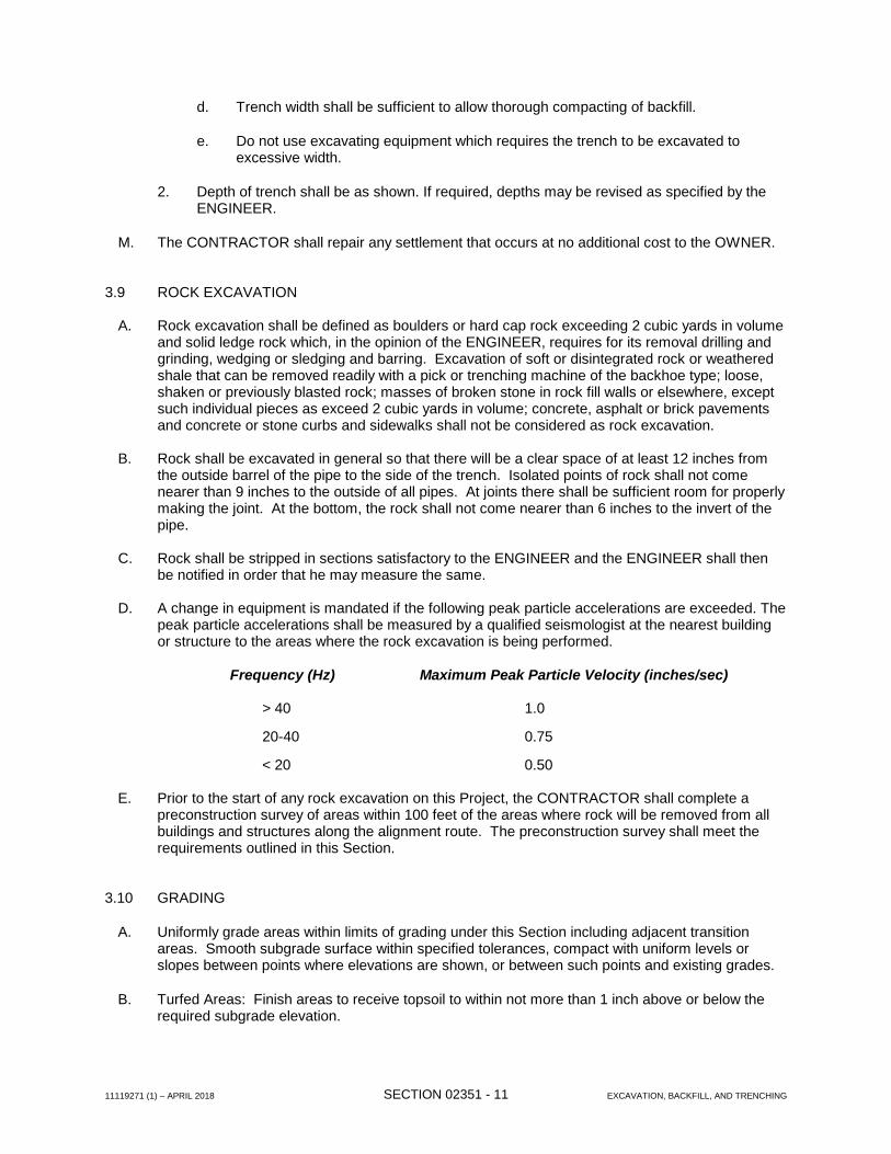
D. A change in equipment is mandated if the following peak particle accelerations are exceeded. The peak particle accelerations shall be measured by a qualified seismologist at the nearest building or structure to the areas where the rock excavation is being performed.
Frequency (Hz) Maximum Peak Particle Velocity (inches/sec) > 40 1.0
20-40 0.75
< 20 0.50
E. Prior to the start of any rock excavation on this Project, the CONTRACTOR shall complete a preconstruction survey of areas within 100 feet of the areas where rock will be removed from all buildings and structures along the alignment route. The preconstruction survey shall meet the requirements outlined in this Section.
3.10 GRADING
A. Uniformly grade areas within limits of grading under this Section including adjacent transition areas. Smooth subgrade surface within specified tolerances, compact with uniform levels or slopes between points where elevations are shown, or between such points and existing grades.
B. Turfed Areas: Finish areas to receive topsoil to within not more than 1 inch above or below the required subgrade elevation.
11119271 (1) – APRIL 2018 SECTION 02351 - 12 EXCAVATION, BACKFILL, AND TRENCHING
C. Walks and Pavements: Shape surface of areas under walks to line, grade and cross-section, with finish surface not more than 1/2 inch above or below the required subgrade elevation.
D. Slabs: Grade smooth and even, free of voids, compacted as specified, and to required elevation. Provide final grades within a tolerance of 3 inch when tested with a 10-foot straightedge.
E. Compaction: After grading, compact subgrade surfaces to the depth and percentage of maximum density required.
F. All existing drainage swales and ditches, if disturbed, shall immediately, upon completion of pipe installation, be restored to proper lines and grades. CONTRACTOR shall ensure the final drainage facilities are in working condition and acceptable to the agency of jurisdiction.
3.11 PAVEMENT SUBBASE COURSE
A. General: Place subbase select fill material, in layers of specified thickness, over ground surface to support the pavement base/binder course.
B. Grade Control: During construction, maintain lines and grades including crown and cross-slope of subbase course.
C. Shoulders: Place shoulders along edges of subbase course to prevent lateral movement. Construct shoulders of acceptable soil materials as specified, placed in such quantity to compact to thickness of each subbase course layer. Compact and roll at least 12 inch width of shoulder simultaneously with compacting and rolling of each layer of subbase course.
D. Placing: Place subbase course material on prepared subgrade in layers of uniform thickness, conforming to indicated cross-section and thickness. Maintain optimum moisture content for compacting subbase material during placement operations. When a compacted subbase course is shown to be 6 inches thick or less, place material in a single layer. When shown to be more than 6 inches thick, place material in equal layers, except no single layer more than 6 inches or less than 3 inches in thickness when compacted.
3.12 DISPOSAL OF EXCAVATED MATERIALS
A. Material removed from the excavations which does not conform to the requirements for fill or is in excess of that required shall be stockpiled at the OWNER’s designated location within the OWNER’s facility at no additional cost to the OWNER.
B. The CONTRACTOR shall not dispose waste excavated material in any of the following locations:
1. Wetland areas.
2. Flood plains.
3. Any area where excess siltation will damage or pollute receiving water.
4. Disposal of excess materials shall only be allowed at locations approved by the agency with jurisdiction.
11119271 (1) – APRIL 2018 SECTION 02351 - 13 EXCAVATION, BACKFILL, AND TRENCHING
3.13 RESTORATION AND CLEAN-UP
A. Following installation, the CONTRACTOR shall restore all areas to their original condition to the requirements of Section 02480 – Landscaping and Restoration, and to the satisfaction of the ENGINEER.
END OF SECTION
11119271 (1) – APRIL 2018 SECTION 02480 - 1 LANDSCAPING AND RESTORATION
SECTION 02480
LANDSCAPING AND RESTORATION PART 1 - GENERAL 1.1 SECTION INCLUDES
A. All labor, materials, equipment and incidentals required to provide landscaping and restoration as shown, specified or required to complete the work.
B. The types of landscaping required include the following:
1. Rough and final grading. 2. Topsoil stockpiled for reuse. 3. Lawn areas. 4. Maintenance work as specified until completion of the Contract. 5. Miscellaneous landscape materials.
C. Restoration of paving and sidewalks, curbs, and gutters are specified under Sections 02500 and
02510 of these Specifications. 1.2 RELATED SECTIONS
A. Related Work Specified Elsewhere 1. Section 02351 – Excavation, Backfill and Trenching
1.3 REFERENCES
A. Comply with the applicable provisions and recommendations of the following except as otherwise shown or specified.
1. ASTM C 602, Agricultural Liming Materials. 2. ASTM D 698, Standard Compaction Test 3. ASTM D 2487, Classification of Soils for Engineering. 4. Association of Official Analytical Chemists, Official Methods of Analysis. 5. American Joint Committee on Horticultural Nomenclature, Standardized Plant Names. 6. Official Seed Analysts of North American, Standards of Quality. 7. FSO-F-241D, Fertilizer, Mixed, Commercial. 8. American Association of Nurserymen (AAN)
11119271 (1) – APRIL 2018 SECTION 02480 - 2 LANDSCAPING AND RESTORATION
1.4 QUALITY ASSURANCE
A. Source Quality Control:
1. General: Ship landscape materials with certificates of inspection as required by governmental authorities. Comply with governing regulations applicable to landscape materials.
2. Topsoil stockpiled for reuse: Topsoil will be inspected by the ENGINEER before reuse. At
the time of inspection the ENGINEER may require representative soil samples to be tested for physical properties, hydrogen-ion value, organic matter, and available phosphoric acid and potassium. Supply twenty-pound samples and make tests at no additional expense to OWNER. If deficiencies in the topsoil are found as a result of this analysis they shall be corrected at no additional expense to the OWNER.
3. Topsoil from off-site sources: Topsoil from off-site sources may be provided for use on this
Project. All topsoil furnished from off-site sources shall be subject to the ENGINEER's approval.
1.5 SUBMITTALS
A. Shop Drawings: Submit for approval the following: 1. Manufacturer's specifications and installation instructions for all materials. 2. The location of source and data for off-site topsoil. 3. Should a hydroseeder be used, the CONTRACTOR shall submit all data including material
and application rates.
B. Certificates: Submit for approval the following: 1. Certificates of inspection as may be required by governmental authorities to accompany
shipments, and manufacturer's or vendor's certified analysis for soil amendments and fertilizer materials. For standard products submit other data substantiating that materials comply with specified requirements.
2. Certificates from seed vendors certified statement for each seed mixture required, stating
botanical and common name, percentage by weight and percentages of purity, germination, and weed seed for each species.
3. Certificate guaranteeing work through the specified maintenance period.
1.6 COORDINATION
A. Review installation procedures under other Sections and coordinate the installation of items that must be installed with the landscaping.
B. Notify other contractors in advance of the installation of the landscaping to provide the other
contractors with sufficient time for the installation of items included in their contracts that must be installed before the landscaping.
11119271 (1) – APRIL 2018 SECTION 02480 - 3 LANDSCAPING AND RESTORATION
1.7 GUARANTEE
A. Guarantee lawns and landscape through the specified maintenance period, and until final acceptance of the Work.
1.8 PRODUCT DELIVERY, STORAGE AND HANDLING
A. Delivery of Materials: Do not deliver materials until site conditions are ready for planting. Deliver packaged materials in containers showing weight, analysis and name of manufacturer. Protect materials from deterioration during delivery. Notify ENGINEER of delivery schedule in advance so plant material may be inspected upon arrival at job site. Remove unacceptable material immediately from job site.
B. Storage of Materials: Store and cover materials to prevent deterioration. Remove packaged
materials that have become wet or show deterioration or water marks from the site. Replace at no further cost to OWNER.
1.9 JOB CONDITIONS
A. Environmental Requirements:
1. Proceed with and complete the Work as rapidly as portions of the site become available, working within the seasonal limitations for each kind of landscape work required.
2. Do not spread seed when wind velocity exceeds 5 miles per hour. 3. Do not plant when drought, or excessive moisture, or other unsatisfactory conditions
prevail.
B. Scheduling:
1. Plant or install materials only during normal planting seasons for each type of landscape work required. Correlate planting with specified maintenance periods to provide maintenance until occupancy by the OWNER.
PART 2 PRODUCTS 2.1 MATERIALS
A. Topsoil:
1. Topsoil will be stockpiled for re-use in landscape work.
B. Soil Amendments:
1. Lime: Natural limestone containing not less than 85 percent of total carbonates, ground so that not less than 90 percent passes a 10-mesh sieve and not less than 50 percent passes a 100-mesh sieve.
2. Peat Humus: Provide peat humus, which is a natural product of either sphagnum moss,
reed, or sedge peat, taken from a fresh water site. Supply shredded material, free from lumps, roots, stones and other extraneous foreign matter, capable of passing through 2-inch screen, which can easily be incorporated with the topsoil. Supply peat humus with
11119271 (1) – APRIL 2018 SECTION 02480 - 4 LANDSCAPING AND RESTORATION
the following analysis:
a. Not less than 90 percent organic matter by weight on an oven dry basis. b. pH range 5 to 7.5. c. Moisture content 35 percent at time of incorporation into soil.
3. Commercial Fertilizer: Complete fertilizer of neutral character, with a minimum of 75
percent nitrogen; 40-50 percent of the nitrogen shall be water-soluble. Available phosphoric acid derived from superphosphate, bone, or tankage. Potash derived from muriate of potash. Uniform in composition, free flowing and suitable for application with approved equipment. Provide fertilizer with the following percentages of available plant nutrients.
a. For lawns, provide fertilizer with not less than 4 percent phosphoric acid and not less
than 2 percent potassium, and the percentage of nitrogen required to provide not less than 1.5 pounds of actual nitrogen per 1000 square feet of lawn area.
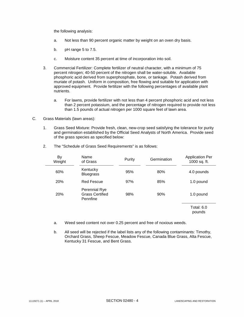
C. Grass Materials (lawn areas):
1. Grass Seed Mixture: Provide fresh, clean, new-crop seed satisfying the tolerance for purity
and germination established by the Official Seed Analysts of North America. Provide seed of the grass species as specified below:
2. The "Schedule of Grass Seed Requirements" is as follows:
By
Weight Name
of Grass
Purity
Germination Application Per
1000 sq. ft.
60% Kentucky
Bluegrass
95%
80%
4.0 pounds
20% Red Fescue 97% 85% 1.0 pound
20%
Perennial Rye Grass Certified Pennfine
98%
90%
1.0 pound
Total: 6.0 pounds
a. Weed seed content not over 0.25 percent and free of noxious weeds. b. All seed will be rejected if the label lists any of the following contaminants: Timothy,
Orchard Grass, Sheep Fescue, Meadow Fescue, Canada Blue Grass, Alta Fescue, Kentucky 31 Fescue, and Bent Grass.
11119271 (1) – APRIL 2018 SECTION 02480 - 5 LANDSCAPING AND RESTORATION
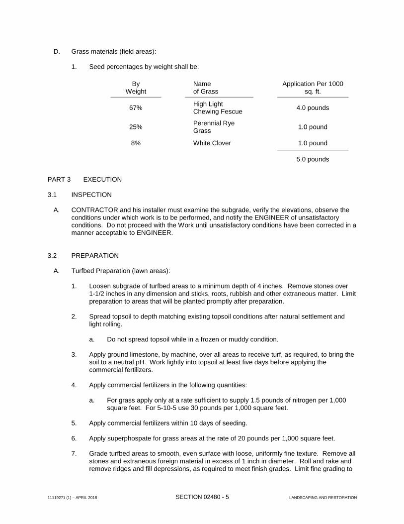
D. Grass materials (field areas):
1. Seed percentages by weight shall be:
By Weight
Name of Grass
Application Per 1000 sq. ft.
67% High Light
Chewing Fescue
4.0 pounds
25% Perennial Rye
Grass
1.0 pound
8% White Clover 1.0 pound
5.0 pounds
PART 3 EXECUTION 3.1 INSPECTION
A. CONTRACTOR and his installer must examine the subgrade, verify the elevations, observe the conditions under which work is to be performed, and notify the ENGINEER of unsatisfactory conditions. Do not proceed with the Work until unsatisfactory conditions have been corrected in a manner acceptable to ENGINEER.
3.2 PREPARATION
A. Turfbed Preparation (lawn areas):
1. Loosen subgrade of turfbed areas to a minimum depth of 4 inches. Remove stones over 1-1/2 inches in any dimension and sticks, roots, rubbish and other extraneous matter. Limit preparation to areas that will be planted promptly after preparation.
2. Spread topsoil to depth matching existing topsoil conditions after natural settlement and
light rolling.
a. Do not spread topsoil while in a frozen or muddy condition.
3. Apply ground limestone, by machine, over all areas to receive turf, as required, to bring the soil to a neutral pH. Work lightly into topsoil at least five days before applying the commercial fertilizers.
4. Apply commercial fertilizers in the following quantities:
a. For grass apply only at a rate sufficient to supply 1.5 pounds of nitrogen per 1,000
square feet. For 5-10-5 use 30 pounds per 1,000 square feet.
5. Apply commercial fertilizers within 10 days of seeding. 6. Apply superphospate for grass areas at the rate of 20 pounds per 1,000 square feet. 7. Grade turfbed areas to smooth, even surface with loose, uniformly fine texture. Remove all
stones and extraneous foreign material in excess of 1 inch in diameter. Roll and rake and remove ridges and fill depressions, as required to meet finish grades. Limit fine grading to
11119271 (1) – APRIL 2018 SECTION 02480 - 6 LANDSCAPING AND RESTORATION
areas which can be planted immediately after grading. 8. Moisten prepared turfbed areas before planting if soil is dry. Water thoroughly and allow
surface moisture to dry before planting. Do not create a muddy soil condition. 9. Restore turfbed areas to specified condition if eroded or otherwise disturbed after fine
grading and prior to planting.
B. Bed preparation (field areas): 1. York rake areas to be seeded. 2. All stones or other undesirable materials over three (3") inches or greater in diameter shall
be removed and disposed of as approved. 3. Swale areas to drain ditches. 4. Fertilize area and lightly rake.
3.3 INSTALLATION
A. Seeding Lawns:
1. Sow seed using a spreader or seeding machine. 2. Distribute seed evenly over entire area by sowing equal quantity in two directions at right
angles to each other. 3. Sow not less than the quantity of seed specified. 4. Protect seeded areas against erosion by spreading specified lawn mulch after completion
of seeding operations. The mulch shall be hand or machine spread to form a continuous blanket over the seed bed, approximately 2-inches uniform thickness at loose measurement.
5. Hydroseeding may be accepted as an alternative method of applying fertilizer, seed and
mulch. The CONTRACTOR must submit all data regarding materials and application rates to the ENGINEER for review.
B. Reconditioning Existing Turf:
1. Recondition existing turf areas damaged by CONTRACTOR'S operations including storage
of materials and equipment and movement of vehicles. Also recondition existing turf areas where minor regrading is required.
2. Provide fertilizer, seed or sod and soil amendments as specified for new turf and as
required to provide a satisfactorily reconditioned turf. Provide topsoil as required to fill low spots and meet new finish grades.
3. Cultivate bare and compacted areas thoroughly to provide a satisfactory planting bed. 4. Remove diseased and unsatisfactory turf areas; do not bury into soil. Remove topsoil
containing foreign materials resulting from CONTRACTOR's operations including oil drippings, stone, gravel and other loose building materials.
11119271 (1) – APRIL 2018 SECTION 02480 - 7 LANDSCAPING AND RESTORATION
5. In areas approved by ENGINEER, where substantial turf remains (but is thin), mow, rake, aerate if compacted, fill low spots, remove humps and cultivate soil, fertilize, and seed. Remove weeds before seeding or if extensive, apply selective chemical weed killers as required. Apply a seedbed mulch, if required, to maintain moist condition.
6. Water newly planted areas and keep moist until new turf is established.
C. Seeding field areas:
1. Fertilize area and lightly rake. 2. Seed area and lightly rake. 3. Cover seeded area with “blown” straw or hand placed straw mulch to retain seed. Seed
shall be applied to a rate of seventy (70) pounds of live seed per acre. 4. Seed and fertilizer shall be placed by Broadcast Spreader, Hydroseeding or Scott Type
Lawn Seeder. 5. Fertilizer shall be a 20-10-5 mixture and be applied at a rate of four hundred (400) pounds
per acre. 6. Mulch shall be straw only, applied at a rate of two (2) tons per acre. 7. If Hydroseeder is used, seed, fertilizer, and mulch shall be applied in one operation. 8 The restoration shall be scheduled in a manner, which will allow the ENGINEER to keep a
close eye on the work to ensure good workmanship. 9. If material is unsuitable for growth, the ENGINEER will determine the location and amount
of topsoil dressing to be applied. 10. CONTRACTOR shall furnish water and water application equipment. Apply water in a
manner which will not damage topsoil, seed and mulch. 3.4 OTHER TYPES OF RESTORATION
A. Shrubs and landscape items damaged or destroyed, as a result of the construction operations shall be replaced in like species and kind.
1. All planting and care thereof shall meet the standards of the American Association of
Nurserymen.
B. Tree Plantings
1. Determine location of underground utilities and perform work in a manner, which will avoid possible damage. Hand excavate, as required, to minimize possibility of damage to underground utilities.
2. Trees replaced by the CONTRACTOR will be of the same species, and will be a minimum
of 6 feet high and 2 inches in trunk diameter. CONTRACTOR must fertilize and water tree appropriately after planting and shall guarantee tree for a period of one year. All issues regarding tree planting including type, size and final location must be approved by the ENGINEER.
11119271 (1) – APRIL 2018 SECTION 02480 - 8 LANDSCAPING AND RESTORATION
C. Water courses shall be reshaped to the original grade and cross-section and all debris removed. Where required to prevent erosion, the bottom and sides of the watercourse shall be protected.
D. Culverts destroyed or removed as a result of the construction operations shall be replaced in the
like size and material, and shall be replaced at the original location and grade.
E. Items removed for construction such as mailboxes, signposts, reflector markers, and the like shall be replaced in good or better condition than existing. Items damaged by the CONTRACTOR shall be replaced at his expense. Privately owned items, such as mailboxes, shall be reinstalled to the satisfaction of the OWNER and ENGINEER.
3.5 MAINTENANCE
A. Begin maintenance immediately after planting. B. Maintain turf for a period as required to establish an acceptable stand, as determined by the
ENGINEER.
C. Maintain lawns by watering, fertilizing, weeding, mowing, trimming and other operations such as rolling, regrading and replanting as required to establish a smooth, acceptable lawn, free of eroded or bare areas.
3.6 CLEANUP AND PROTECTION
A. During landscape work, store materials and equipment where directed. Keep pavements clean and work area in an orderly condition.
B. Protect landscape work and materials from damage due to landscape operations, operations by
other contractors and trades and trespassers. Maintain protection during installation and maintenance periods. Treat, repair or replace damaged landscape work as directed.
C. Remove all rubbish, equipment and rejected materials from the site. D. Protection includes all temporary fences, barriers and signs and other work incidental to proper
maintenance. 3.7 INSPECTION AND ACCEPTANCE
A. When the landscape work is completed, including maintenance, the ENGINEER will make an inspection to determine acceptability.
B. Where inspected landscape work does not comply with the requirements, replace rejected work
and continue specified maintenance until reinspected by the ENGINEER and found to be acceptable. Remove rejected plants and materials promptly from the Project Site.
END OF SECTION
11119271 (1) - APRIL 2018 SECTION 03300 - 1 CONCRETE
SECTION 03300
CONCRETE PART 1 GENERAL 1.1 DESCRIPTION
A. Work Specified.
1. All cast-in-place concrete used in the construction of floor and wall repairs, equipment pads, and other sections of restoration.
2. Reinforcing steel, form work, and items of concrete accessories required for the completion of the work.
B. Related Work Specified Elsewhere.
1. General Provisions.
1.2 QUALITY ASSURANCE
A. References.
1. ACI 211, Proportioning Concrete Mixtures.
2. ACI 304, Measuring, Mixing, Transporting, and Placing Concrete.
3. ACI 305R, Hot Weather Concreting.
4. ACI 306, Cold Weather Concreting.
5. ACI 309R, Consolidation of Concrete.
6. ASTM A185, Standard Specifications for Steel Welded Wire Fabric, Plain for Concrete Reinforcement.
7. ASTM A615, Standard Specifications for Deformed and Plain Billet-Steel Bars for Concrete Reinforcement.
8. ASTM C33, Standard Specifications for Concrete Aggregates.
9. ASTM C94, Standard Specifications for Ready-Mixed Concrete.
10. ASTM C150, Standard Specifications for Portland Cement.
11. ASTM C260, Standard Specifications for Air-Entraining Admixtures for Concrete.
12. ASTM C309, Standard Specifications for Liquid Membrane-Forming Compounds for Curing Concrete.
13. ASTM C494, Standard Specifications for Chemical Admixtures for Concrete.
11119271 (1) - APRIL 2018 SECTION 03300 - 2 CONCRETE
14. ASTM D1751, Standard Specifications for Preformed Expansion Joint Filler for Concrete Paving and Structural Construction.
B. Tests
1. All previous testing of non-concrete materials incorporated in the concrete mix shall be performed within the past 12 months. Make test reports available to the ENGINEER upon request.
2. For each day when concrete is being placed, provide one slump test and three cylinders for compression testing. One cylinder shall be tested at 7 days and two cylinders at 28 days. Submit all copies of test results to ENGINEER for review.
1.3 SUBMITTALS
A. Name and location of concrete supplier.
B. Concrete mix design indicating amount of all ingredients for concrete to be used in the Work.
C. Manufacturer’s literature for curing compounds, joint materials, admixtures, form coatings, manufactured form systems, ties, etc.
D. Laboratory test results; compression cylinder test results from previous projects may be used for verification of design.
E. Certified copies of all required test reports.
F. Certificates of Compliance with referenced standards.
PART 2 PRODUCTS
2.1 MATERIALS
A. ACI Code.
Except as otherwise shown on the Contract Drawings or specified herein, “Building Code Requirements for Reinforced Concrete” (ACI 318, latest revision) shall apply.
B. Class “A” Concrete as referred to in this section is defined as Structural Concrete which includes reinforcing and formwork.
Class “B” Concrete as referred to in this section is defined as General Concrete which includes little or no reinforcing and simple or no formwork.
C. Portland Cement
1. Conform to ASTM C150, Type II, unless noted otherwise.
2. Conform to ASTM C150, Type III for high early-strength concrete.
3. Type I or III may be employed with the ENGINEER’s approval.
11119271 (1) - APRIL 2018 SECTION 03300 - 3 CONCRETE
D. Fine and Coarse Aggregates
1. Comply in all respects to ASTM C33.
2. Maximum size of coarse aggregate: 1 – 2 inches; 3/4-inch for precast structures.
3. Coarse aggregate for concrete used for sidewalks, curbs, and gutters shall be crushed limestone or approved equal.
E. Water: Potable and complying with ASTM C94.
F. Admixtures.
1. Water Reducing - conform to ASTM C494, Type A.
2. Air-Entraining - conform to ASTM C260.
G. Reinforcing steel bars shall be deformed new billet steel conforming to ASTM A615, Grade 60. Welded wire fabric shall be cold drawn steel conforming to ASTM A185.
H. Expansion joint material shall be ASTM D1751, asphalt-saturated cellulosic fiber, 1/2-inch thickness and of the width required for full depth joints.
I. Membrane curing compound shall be pigmented and conform to the requirements of ASTM C309, Type 1, Class B.
J. Grout: All grout shall be non-shrink, non-metallic, non-gas forming, preblended and ready for use requiring only the addition of water. Minimum 28-day compressive strength must be 5000 psi.
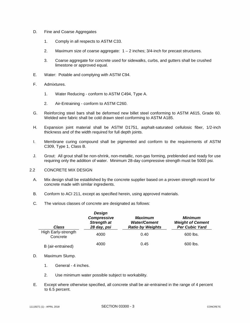
2.2 CONCRETE MIX DESIGN
A. Mix design shall be established by the concrete supplier based on a proven strength record for concrete made with similar ingredients.
B. Conform to ACI 211, except as specified herein, using approved materials.
C. The various classes of concrete are designated as follows:
0BClass
Design 1BCompressive Strength at 28 day, psi
Maximum
Water/Cement 2BRatio by Weights
Minimum
Weight of Cement 3BPer Cubic Yard
High Early-strength Concrete
B (air-entrained)
4000
4000
0.40
0.45
600 lbs.
600 lbs.
D. Maximum Slump.
1. General - 4 inches.
2. Use minimum water possible subject to workability.
E. Except where otherwise specified, all concrete shall be air-entrained in the range of 4 percent to 6.5 percent.
11119271 (1) - APRIL 2018 SECTION 03300 - 4 CONCRETE
2.3 BATCHING AND MIXING
A. Batching.
1. The CONTRACTOR shall have a modern and dependable batch plant within a reasonable distance from the work at his disposal.
2. Comply with ACI 304.
3. Use only approved materials.
B. Mixing and Delivery.
1. Comply with ASTM C94, and furnish batch ticket information. PART 3 EXECUTION
3.1 CONCRETE PLACEMENT
A. Forms shall be substantially free from surface defects and sufficiently tight to prevent leakage of mortar. They shall be properly braced and tied so as to maintain position and shape during and after placing of concrete.
B. The CONTRACTOR shall build into the concrete reinforcing steel, sleeves, waterstops, etc., as shown on the Contract Drawings, or in restoration work, reinforcing steel and other embedded items equal to that found in the concrete being replaced.
C. All concrete shall be thoroughly consolidated by the use of vibrators or by spading or puddling sticks and tampers in accordance with ACI 309R.
1. No concrete shall be deposited under water without written permission of the ENGINEER and then only in accordance with proper tremie techniques.
D. Cold weather placement: Comply with ACI 306.1.
E. Hot weather placement: Comply with ACI 305R.
3.2 FINISHING
A. All formed concrete surfaces to be exposed shall be given a rubbed finish. In the case of restoration, the rubbed finish shall be equal to that of the concrete surface being replaced.
B. Inverts, benchwalls, floors or structures and similar surfaces shall be given a float finish.
3.3 CURING
A. Concrete shall be maintained in a moist condition for seven (7) days using methods that will insure complete and continuous saturation.
B. Maintain High Early Strength concrete temperature after installation at a minimum 50 degrees F for minimum three (3) days.
11119271 (1) - APRIL 2018 SECTION 03300 - 5 CONCRETE
3.4 NON-SHRINK GROUTING
A. For openings that are left in new concrete or where made in existing concrete for the insertion of wall castings, pipes or other fixtures, the space around these items shall be made watertight by completely filling with a non-shrink grout unless another means is specified elsewhere in the Contract Documents.
B. All work shall be done in strict accordance with the manufacturer’s recommendations. 3.5 QUALITY CONTROL
A. The CONTRACTOR shall be solely responsible for the quality control of all concrete.
B. Concrete which does not meet the requirements of these specifications may be rejected by the ENGINEER.
C. Field Inspection: Testing shall be performed in accordance with Contract Specifications.
END OF SECTION
11119271 (1) - APRIL 2018 SECTION 03600 - 1 GROUT
SECTION 03600
GROUT PART 1 GENERAL 1.1 SECTION INCLUDES
A. This Section includes the minimum requirements of grout used for equipment bases, pipe supports, and anchor rods/bolts including, but not limited to, the following:
A. Section 01010 – Summary of Work. 1.3 REFERENCES
A. Comply with applicable provisions and recommendations of the following, except as otherwise specified.
1. ASTM C 144, Aggregate and Masonry Mortar 2. ASTM C 150, Portland Cement 3. ASTM C 109, Compressive Strength of Hydraulic Cement Mortars (using 2-in. or 50 mm.
Cube Specimens). 4. ASTM C 191, Time of Setting of Hydraulic Cement by Vicat Needle. 5. CRD-C-5898, Specifications for Non-Shrink Grout.
1.4 SUBMITTALS
A. Shop Drawings:
1. Submit copies of manufacturer's specifications and installation instructions for all materials.
B. Reports and Certificates:
1. For proprietary materials, submit copies of reports on quality control tests.
2. For nonproprietary materials, submit certification that materials meet specification requirements.
1.5 QUALITY ASSURANCE
A. Perform work in accordance with applicable ACI model code.
11119271 (1) - APRIL 2018 SECTION 03600 - 2 GROUT
PART 2 PRODUCTS 2.1 MANUFACTURERS
A. The following shall be used for grout work where otherwise unspecified:
1. Non-shrink, epoxy type grout shall be Masterflow 648 by BASF Corporation, E3-Flowable by Euclid Chemical Corporation, or approved equal.
2. Non-shrink, non-metallic cementitious grout shall be Masterflow 928 by BASF Corporation,
Hi-Flow Grout by Euclid Chemical Corporation, or approved equal. 2.2 MATERIALS
A. Non-shrink, epoxy type grout for applications including anchor rods/bolts.
1. Grout shall be a non-shrink, high-performance, three-component, 100 percent solids, moisture tolerant, high strength, modified epoxy resin-based grout.
2. Grout shall conform to current ASTM 881 specifications. 3. Grout shall have the following minimum property values in accordance with test standard:
a. 7-day compressive strength: 11,500 psi (ASTM C579). b. Flexural strength: 3,900 psi (ASTM C580). c. Tensile strength: 1,900 psi (ASTM C307).
B. Non-shrink, non-metallic cementitious grout for structural applications including bearing plates and base plates.
1. Grout shall have the following minimum property values in accordance with test standard:
a. 28-day compressive strength (flowable state): 8,000 psi (ASTM C109, ASTM C942). b. Compliance with ASTM C1107 and CRD 621.
PART 3 EXECUTION 3.1 EXAMINATION
A. CONTRACTOR shall, prior to placing grout, inspect all areas to be grouted to ensure that no defects exist that may inhibit the intended use of the grout. If such conditions occur, CONTRACTOR shall make notice to ENGINEER and proceed only when directed by ENGINEER.
3.2 PREPARATION
A. Prior to placing grout, CONTRACTOR shall clean concrete surfaces of dirt, dust, laitance, corrosion, or other contamination; wire brush; using potable water, rinse surface and allow it to dry.
11119271 (1) - APRIL 2018 SECTION 03600 - 3 GROUT
3.3 INSTALLATION
A. General:
1. Place grout as shown on the Contract Drawings and in accordance with manufacturer’s instructions. If manufacturer’s instructions conflict with the Specifications, do not proceed until ENGINEER provides clarification.
2. Manufacturers of proprietary products shall make available, upon 72 hours notification, the
services of a qualified, full-time employee to aid in assuring proper use of the product under job conditions.
3. Placing grout shall conform to temperature and weather limitations as specified by the
manufacturer. 4. Equipment base grouting shall be conducted to ensure no voids exist under bases. Grout
shall be worked from one end of the base to the other. On large bases, stand pipes, grout holes, and vents shall be provided to ensure base is properly grouted.
A. Ferrous metal components, including miscellaneous shapes, plates, anchor rods, bolts, and accessories.
1.2 RELATED SECTIONS
A. Section 01010 – Summary of Work. 1.3 SUBMITTALS
A. Provide Shop Drawings for special assemblies and construction details as required by the OWNER/ENGINEER. This includes, but is not limited to the following items:
1. Shop Drawings: Show fabrication and installation of all items, including plans, elevations,
sections, details of components, joint locations and configurations within system and between system and construction penetrating it, termination details, and attachments to construction behind system.
2. Details of conditions unique to the Project. This includes details indicated on the Contract Drawings, details to address specific job conditions, or details which the CONTRACTOR may propose to use which differ from those indicated on the Contract Drawings.
1.4 QUALITY ASSURANCE
A. Qualifications: The CONTRACTOR is to have satisfactorily performed work of similar scope on projects of similar type for a minimum of 5 years.
B. Regulatory Requirements: All work is to be completed in accordance with all the latest
requirements of the following authorities and/or documents the most stringent requirements of which will apply:
1. American Institute of Steel Construction.
2. American Society for Testing and Materials.
3. American Welding Society.
C. Weld procedures and welder personnel shall be AWS qualified. Keep procedures and certifications on file. Submit only when requested.
1.5 DELIVERY, STORAGE, AND HANDLING
A. Deliver materials to the Site as required for use in a manner which will not delay construction.
B. Store materials inside and under cover, keep them dry and protected from the weather, surface contamination, aging, corrosion, damage from construction traffic or other causes.
1.6 COORDINATION AND SCHEDULING A. Coordinate fabrication schedule with construction progress to avoid delaying the work. B. Supply anchorage items to be embedded in or attached to other construction without delaying the
work. Provide setting diagrams, templates, instructions, and directions, as required, for installation.
C. Coordinate work with existing field conditions.
D. Field verify all dimensions prior to submittal of shop drawings.
E. Coordinate placement of concrete with installation of cast-in embedded items.
PART 2 PRODUCTS
2.1 MATERIALS
A. “W”-Shaped Steel Beams - ASTM A992, Grade 50.
B. “S”-Shaped Steel Beams - ASTM A36 or ASTM A992, Grade 50.
C. “C”-Shaped or “MC”-Shaped Steel Channels - ASTM A36 or ASTM A572 Grade 50.
as a manufactured fastener assembly to comply with ASTM A153 or F2329; ASTM A489 steel lifting eyes.
N. All bolt accessories including nuts, washers, etc. shall be of the same material as the bolt.
O. Dielectric separation (i.e., neoprene washers) shall be used when a fastener material may be
reactive to the base material.
P. Bolted Attachment to Concrete and Masonry – For structural connections, use stainless steel threaded rods with chemical adhesive anchor system. Expansion anchors are not allowed unless specifically requested for a particular application and approved by ENGINEER.
R. Welding Filler Metals and Electrodes - AWS D1.1, D1.2, D1.3, and D1.6.
1. For steel welding, filler metal shall conform to AWS 5.1 or 5.5 and E70xx SMAW electrodes shall be used.
2. Required type(s) for other materials being welded.
S. Touch-Up Primer for Galvanized Surfaces - Zinc-rich paint.
2.2 FINISHES
A. Prepare steel surfaces in accordance with SSPC SP-6.
B. Shop prime paint steel items, not galvanized, and top coat after installation. Prime paint shall be compatible with paint (coating) system specified. Do not prime surfaces where field welding is required.
C. Galvanized items shall be hot-dip galvanized in accordance with ASTM A123 or A153. Provide
minimum 2.0 oz/sq.ft. galvanized coating.
D. Unless noted otherwise, aluminum shall be mill finish.
E. Aluminum in contact with concrete or masonry shall be backpainted with bituminous paint.
PART 3 EXECUTION 3.1 EXAMINATION
A. Ensure that field conditions are acceptable and are ready to receive work. Measurements and
dimensions to be field verified.
B. Beginning of installation means CONTRACTOR has verified and accepts existing conditions.
3.2 FABRICATION
A. Fit and shop assemble in largest practical sections, for delivery to site.
B. Fabricate items with joints tightly fitted and secured.
C. Welds shall be continuous unless noted otherwise. Grind down welds smooth to remove excess material.
D. Exposed Mechanical Fastenings - Unobtrusively located, consistent with design of component.
E. Supply components required for anchorage of fabrications.
3.4 FABRICATION TOLERANCES
A. Squareness - 1/8-inch maximum difference in diagonal measurements.
B. Maximum Offset Between Faces - 1/16-inch.
C. Maximum Misalignment of Adjacent Members - 1/16-inch.
D. Maximum Bow - 1/8-inch in 48 inches.
E. Maximum Deviation From Plane - 1/16-inch in 48 inches.
3.5 INSTALLATION
A. Allow for erection loads and provide sufficient temporary bracing to maintain true alignment until completion of erection and installation of permanent attachments.
B. Install items plumb and level, accurately fitted, free from distortion or defects.
C. Install manufactured items in accordance with manufacturer’s instructions.
D. Install and secure all cast-in (embedded) items prior to placement of concrete or grouting of
masonry.
E. Perform field welding in accordance with AWS.
F. Fasten aluminum fabrications using Type 316 stainless steel bolts and accessories.
G. Fasten galvanized steel fabrications using A325 galvanized bolts and accessories unless Type 316 stainless steel bolts and accessories are otherwise indicated in the Contract Documents.
H. Carbon steel bolts shall only be used for painted carbon steel framing connections.
I. Isolate dissimilar metals with dielectric and use appropriate fasteners.
J. Obtain OWNERENGINEER approval prior to site cutting or making adjustments not indicated on shop drawings.
K. Prior to installation, aluminum surfaces in contact with concrete and/or masonry require backpainting.
L. After erection, touch up paint welds, bolts, connection material, and abrasions.
M. Top paint all exposed steel that is not galvanized, except as required for overhead door frames,
ACCESS HATCHES PART 1 GENERAL 1.1 SECTION INCLUDES
A. This Section includes the minimum requirements to supply and install access hatches with safety grates of the sizes and quantities shown on the Contract Drawings as specified herein.
1.2 RELATED SECTIONS
A. Division 3 – Concrete Products
B. Section 06615 – Fiberglass Reinforced Plastic Grating 1.3 QUALIFICATIONS
A. Manufacturer shall be a company specializing in manufacturing products specified in this Section with a minimum of 3 years' experience.
1.4 SUBMITTALS
A. Submit for approval Shop Drawings of design and construction details of all products.
B. Shop Drawings for the fabrication and erection of all assemblies and associated metal fabrications.
C. Copies of manufacturer's specifications, load tables, dimension diagrams, anchor diagrams and
installation instructions for products to be used for access hatch assemblies.
1. Access hatches shall be supplied pre-assembled from the manufacturer with number of leafs as shown on the Contract Drawings.
2. Covers shall be rated for human traffic loading.
a. Operation of the cover shall be smooth and easy with controlled operation throughout
the entire arc of opening and closing. b. Operation of the cover shall not be affected by temperature.
c. Entire door, including all hardware components, shall be Type 316 stainless steel and be highly corrosion resistant.
3. Frame: Channel frame shall be Type 316 stainless steel with bend down anchor tabs
around the perimeter. A continuous EPDM gasket shall be mechanically attached to the frame to create a barrier around the entire perimeter of the cover and significantly reduce the amount of dirt and debris that may enter the channel frame.
4. Hinges: Shall be specifically designed for horizontal installation and shall be through bolted
to the cover with tamperproof Type 316 stainless steel lock bolts and shall be through bolted to the frame with Type 316 stainless steel bolts and locknuts.
5. Drain Coupling: Provide a 1-1/2-inch (38 mm) drain coupling located in the right front
corner of the channel frame.
6. Lifting mechanisms: Manufacturer shall provide the required number and size of compression spring operators enclosed in telescopic tubes to provide, smooth, easy, and controlled cover operation throughout the entire arc of opening and to act as a check in retarding downward motion of the cover when closing. The upper tube shall be the outer tube to prevent accumulation of moisture, grit, and debris inside the lower tube assembly. The lower tube shall interlock with a flanged support shoe fastened to a formed 1/4-inch gusset support plate.
7. An exterior handle shall be provided to open the cover.
8. Hardware:
a. Hinges: Stainless steel hinges, each having a minimum 1/4-inch (6.3 mm) diameter
Type 316 stainless steel pin, shall be provided and shall pivot so the cover does not protrude into the channel frame.
b. Cover shall be equipped with a hold open arm which automatically locks the cover in the open position.
c. Cover shall be fitted with the required number and size of compression spring operators. Springs shall have an electrocoated acrylic finish. Spring tubes shall be constructed of a reinforced nylon 6/6 based engineered composite material.
d. A Type 316 stainless steel snap lock with fixed handle shall be mounted on the underside of the cover.
e. Hardware: Shall be Type 316 stainless steel throughout.
a. The hatches shall be equipped with hinged underside stainless steel safety grating for fall protection purposes. Grating panel(s) shall lock automatically in the full open position, and have a provision for locking to prevent unauthorized access. Panels shall be designed to meet OSHA 29 CFR 1910.23 requirements for fall protection.
PART 3 EXECUTION 3.1 EXAMINATION
A. CONTRACTOR shall verify that all items provided by other sections of Work are properly sized and located.
3.2 INSTALLATION
A. Hatches shall be installed and set in accordance with the manufacturer's recommendations and as outlined herein.
END OF SECTION
11119271 (1) - APRIL 2018 SECTION 06615 - 1 Fiberglass Reinforced Plastic (FRP) Grating and Structural Shapes
SECTION 06615
FIBERGLASS REINFORCED PLASTIC (FRP) GRATING AND STRUCTURAL SHAPES
PART 1 GENERAL
1.1 SECTION INCLUDES
A. This section includes shop fabricated fiberglass reinforced plastic (FRP) pultruded fiberglass gratings, hatches, stairs, treads, ladder and structural shapes where noted on the drawings.
1.2 RELATED DOCUMENTS
A. Drawings and general provisions of Contract, including Division 1 Specification Sections, apply to this section.
B. The FRP Composite Fiberglass Grating Manual, ACMA, latest edition
C. The publications listed below (latest revision applicable) form a part of this specification to the extent referenced herein. The publications are referred to within the text by the designation only.
1. ASTM D-635-Standard Test Method for Rate of Burning and/or Extent and Time of Burning of Plastics in a Horizontal Position
3. ASTM D-696-Coefficient of Linear Thermal Expansion for Plastics
4. ASTM E-84-Surface Burning Characteristics of Building Materials
5. THE OCCUPATIONAL HEALTH AND SAFETY ADMINISTRATION (OSHA) Code of Federal Regulations (CFR), Volume 29
1.3 SCOPE OF WORK
A. The CONTRACTOR shall furnish, and install all fiberglass reinforced plastic (FRP) items, with all appurtenances, accessories and incidentals necessary to produce a complete, operable and serviceable installation as shown on the Contract Drawings and as specified herein, and in accordance with the requirements of the Contract Documents.
1.4 CONTRACTOR SUBMITTALS
A. The CONTRACTOR shall furnish shop drawings of all fabricated systems and accessories in accordance with the provisions of this Section.
B. The CONTRACTOR shall furnish manufacturer's shop drawings clearly showing material sizes, types, styles, part or catalog numbers, complete details for the fabrication and erection of components including, but not limited to, location, lengths, type and sizes of fasteners, ledge angles, embedded angles, member sizes, and connection details.
11119271 (1) - APRIL 2018 SECTION 06615 - 2 Fiberglass Reinforced Plastic (FRP) Grating and Structural Shapes
C. The CONTRACTOR shall submit the manufacturer's published literature including structural properties and design data, fiberglass grating load/deflection tables, corrosion resistance tables, certificates of compliance, test reports as applicable, concrete anchor systems and their allowable load tables, and design calculations for systems not sized or designed in the contract documents.
D. The CONTRACTOR may be requested to submit sample pieces of each item specified herein for acceptance by the ENGINEER as to quality and color. Sample pieces shall be manufactured by the method to be used in the Work.
E. The CONTRACTOR shall provide calculations and drawings sealed by a Registered Professional Engineer.
1.5 QUALITY ASSURANCE
A. All items to be provided under this Section shall be furnished only by manufacturers having experience in the design and manufacture of similar products and systems. If requested, experience shall be demonstrated by a record of at least five (5) previous, separate, similar successful installations in the last five (5) years.
B. Substitution of any component or modification of system shall only be allowed when approved by the ENGINEER.
C. Fabricator Qualifications: Firm experienced in successfully producing FRP fabrications similar to that indicated for this project, with sufficient production capacity to produce required units without causing delay in the work.
D. In addition to requirements of these specifications, comply with manufacturer's instructions and recommendations for work.
1.6 DESIGN CRITERIA
A. The design criteria of the FRP products including connections shall be in accordance with governing building codes and generally accepted standards in the FRP industry.
B. Fiberglass Structural Shapes:
1. The design of FRP products including connections shall be in accordance with governing building codes and standards as applicable.
2. Structural members shall be designed to support all applied loads. Deflection in any direction shall not be more than L/360 of span for structural members. Connections shall be designed to transfer the loads.
C. Fiberglass Gratings and Covers:
1. Design live loads of the FRP gratings and covers for walkway applications shall be 100 psf uniformly distributed load (or as required by the governing building code),
2. A maximum deflection of 3/8-inch or L/180 at the center of a simple span OR a concentrated load of 250 pounds with a maximum deflection of 1/4-inch at the center of a simple span.
11119271 (1) - APRIL 2018 SECTION 06615 - 3 Fiberglass Reinforced Plastic (FRP) Grating and Structural Shapes
D. Stair Treads:
1. Stair treads shall be designed for a uniform live load of 100 psf on the simple span of the tread OR a 300 pound live load at the center of the tread, whichever produces the greater stress.
E. Hand Rails:
1. Hand Rails shall withstand the following loads and stresses within limits and under conditions indicated:
a. Uniform Load of 50 lb/ft applied in any direction.
b. Concentrated load of 200 lbf applied in any direction.
c. Uniform and concentrated loads need not be assumed to act concurrently.
1.7 PRODUCT DELIVERY AND STORAGE
A. All gratings and components shall be shop fabricated, piece match marked to assembly or erection drawings.
B. Delivery of Materials: Manufactured materials shall be delivered in original, unbroken pallets, packages, containers, or bundles bearing the label of the manufacturer. Adhesives, resins and their catalysts and hardeners shall be crated or boxed separately and noted as such to facilitate their movement to a dry indoor storage facility.
C. Storage of Products: All materials shall be carefully handled to prevent them from abrasion, cracking, chipping, twisting, other deformations, and other types of damage. Store items in an enclosed area and free from contact with soil and water. Store adhesives, resins and their catalysts and hardeners in dry indoor storage facilities between 70 and 85 degrees Fahrenheit (21 to 29 degrees Celsius) until they are required.
PART 2 PRODUCTS
2.1 MANUFACTURER
A. Fibergrate;
B. American Grating, LLC., AMD Inc.;
C. Fiberglass Grating Systems;
D. Or approved equal.
2.2 GENERAL
A. All FRP items under this Section shall be composed of fiberglass reinforcements and resins in qualities, quantities, properties, arrangements and dimensions as necessary to meet the design requirements and dimensions as specified in the Contract Documents.
11119271 (1) - APRIL 2018 SECTION 06615 - 4 Fiberglass Reinforced Plastic (FRP) Grating and Structural Shapes
B. Fiberglass reinforcement shall be a combination of continuous roving, continuous strand mats and/or surfacing veils in sufficient quantities as needed by the application and/or physical properties required.
C. Resin shall be VINYLESTER (VEFR) for all systems. Fiberglass gratings shall only be MOLDED which shall be vinyl ester resin system, with chemical formulations as necessary to provide the corrosion resistance, strength and other physical properties as required.
D. All finished surfaces of FRP items and fabrications shall be smooth, resin rich, free of voids and without dry spots, cracks, crazes or unreinforced areas. All glass fibers shall be well covered with resin to protect against their exposure due to wear or weathering.
E. All FRP fiberglass gratings and systems shall have a tested flame spread rating of 25 or less when tested in accordance with the ASTM E 84 Tunnel Test. Fiberglass gratings shall also have a tested burn time of less than 30 seconds and an extent of burn rate of less than or equal to 10 millimeters per ASTM D635. Manufacturer may be required to provide certification of ASTM E84 test on fiberglass grating panels from an independent testing laboratory.
F. All fiberglass grating clips and hardware shall be manufactured of Type 316-SS.
G. After fabrication, all cut ends, holes and abrasions of FRP grating shall be sealed with a resin comparable to the fiberglass grating panel.
2.3 FIBERGLASS STRUCTURAL SHAPES
A. Material:
1. Structural shapes and plates shall be made from a premium grade polyester or vinyl ester resin with fire retardant additives to meet Class 1 flame rating of ASTM E-84 and meet all the self-extinguishing requirements of ASTM D-635. All structural shapes shall contain a UV inhibitor.
B. Process:
1. Manufactured by the pultrusion process.
2. Structural FRP members composition shall consist of a glass fiber reinforced polyester or vinyl ester resin matrix, approximately 50 percent resin to glass ratio. A synthetic surface veil shall be the outermost layer covering the exterior surfaces. Glass strand rovings shall be used internally for longitudinal strength. Continuous strand glass mats shall be used internally for transverse strength.
2.4 MOLDED FIBERGLASS GRATING AND TREADS:
A. Manufacture:
1. The grating shall be one piece construction with the tops of the bearing bars and cross bars in the same plane.
2. The mesh pattern and thickness shall be 1-1/2-inch square mesh, 1-1/2-inch thick.
3. The FRP molded grating and treads shall be manufactured by the open mold process.
B. Non slip surfacing: Fiberglass grating shall be provided with a quartz grit bonded to the top surface of the finished grating product.
11119271 (1) - APRIL 2018 SECTION 06615 - 5 Fiberglass Reinforced Plastic (FRP) Grating and Structural Shapes
C. Fire rating: Fiberglass grating shall be fire retardant with a tested flame spread rating of 25 or less when tested in accordance with ASTM E 84. Manufacturer may be required to provide certification of ASTM E84 test on fiberglass grating panels from an independent testing laboratory. Test data shall be from full scale testing of actual production fiberglass grating, of the same type and material supplied on the project.
D. Resin system: The resin system used in the manufacture of the fiberglass grating shall be VEFR. Manufacturer may be required to submit corrosion data from tests performed on actual fiberglass products in standard chemical environments.
E. Color: To be determined by OWNER.
F. Substitutions: Other products of equal strength, stiffness, corrosion resistance and overall quality may be submitted with the proper supporting data to the ENGINEER for approval.
2.5 STAIR TREADS
A. Stair treads shall be fabricated from above fiberglass grating.
B. 1-1/2-inch thick molded stair treads in a 1-1/2-inch by 6-inch rectangular mesh pattern. The resin system shall be the same as the molded grating. The stair tread shall come complete with anti-slip nosing.
C. Non slip surfacing: Stair treads shall be manufactured with a grit surface for slip resistance. For additional safety, and to meet OSHA requirements, stair treads shall be manufactured with a 1 1/2-inch wide nosing of contrasting color. Nosing shall be gritted with an angular quartz grit.
2.6 HANDRAILS AND RAILINGS:
A. FRP handrails shall be molded type VFR and be a standard two rail system.
B. Design shall satisfy OSHA load and dimensional regulations listed in the Code of Federal Regulations, Title 29, as well as local building codes, whichever is more stringent.
2.7 ACCESS LADDER
A. Resin system: The resin system used in the manufacture of the fiberglass grating shall be VEFR. Manufacturer may be required to submit corrosion data from tests performed on actual fiberglass products in standard chemical environments.
B. Ladder shall be of one piece construction. The FRP molded ladder shall be manufactured by the open mold process.
C. Non slip surfacing: ladder rungs shall be manufactured with a grit surface for slip resistance.
D. Access ladder shall be installed with a “ladder-up” device.
2.8 FLOOR COVERS
A. Floor covers shall be fabricated from above fiberglass grating and by the same manufacture as grating system.
B. Floor covers shall incorporate a solid FRP sheet with grating.
C. Non slip surfacing: covers shall be manufactured with a grit surface or slip resistance.
11119271 (1) - APRIL 2018 SECTION 06615 - 6 Fiberglass Reinforced Plastic (FRP) Grating and Structural Shapes
D. ProvideEZ- fiberglass support angle to attach to concrete floor opening.
E. Provide viton gasket attached to fiberglass support angle to seal opening from gas movement.
2.9 FRP STAIRWAYS AND PLATFORMS
A. All new stairways and platforms indicated on the drawings shall be designed per the requirements of this section. Design shall include treads, guardrails, handrails, stringers, framing members, fasteners, and connection angles.
B. Materials shall conform to project specifications.
C. Design shall satisfy OSHA load and dimensional regulations listed in the Code of Federal Regulations, Title 29, as well as local building codes, whichever is more stringent.
D. Stairs and platforms shall be designed to resist environmental loads listed in the local building code including snow, ice, wind, and seismic loads, as required.
PART 3 EXECUTION
3.1 GENERAL
A. Measurements - FRP grating systems supplied shall meet the dimensional requirements and tolerances as shown or specified. The CONTRACTOR shall provide and/or verify measurements in field for work fabricated to fit field conditions as required by manufacturer to complete the work. When field dimensions are not required, CONTRACTOR shall determine correct size and locations of required holes or cutouts from field dimensions before grating fabrication.
B. Sealing - All shop-fabricated cuts, drilled holes, etc. shall be coated with resin to provide maximum corrosion resistance. All field fabricated cuts, drilled holes, etc. shall be coated similarly by the CONTRACTOR in accordance with the manufacturer's instructions.
C. Hardware - Type 316 stainless steel hold-down clips shall be provided and spaced at a maximum of four feet apart with a minimum of four per piece of fiberglass grating, or as recommended by the manufacturer.
D. Fiberglass Grating Layout - Each fiberglass grating section shall be readily removable, except where indicated on drawings. Manufacturer to provide openings and holes where located on the Contract Drawings. Fiberglass grating openings which fit around protrusions (pipes, cables, machinery, etc.) shall be discontinuous at approximately the centerline of opening so each section of grating is readily removable. Fiberglass gratings shall be fabricated free from warps, twists, or other defects which affect appearance and serviceability.
3.2 INSPECTION
A. Shop inspection is authorized as required by the OWNER and shall be at OWNER'S expense. The fabricator shall give ample notice to CONTRACTOR prior to the beginning of any fabrication work so that inspection may be provided.
B. The fiberglass grating shall be as free, as commercially possible, from visual defects such as foreign inclusions, delaminations, blisters, resin burns, air bubbles and pits. The surface shall have a smooth finish (except for grit top surfaces).
11119271 (1) - APRIL 2018 SECTION 06615 - 7 Fiberglass Reinforced Plastic (FRP) Grating and Structural Shapes
3.3 INSTALLATION
A. CONTRACTOR shall install FRP fiberglass gratings, ladders, stairways, handrails and railings in accordance with manufacturer's assembly drawings.
B. Lock fiberglass grating panels securely in place with hold-down fasteners as specified herein.
C. Field cut and drill fiberglass reinforced plastic products with carbide or diamond tipped bits and blades. Seal cut or drilled surfaces in accordance with manufacturer's instructions. Follow manufacturer's instructions when cutting or drilling fiberglass products or using resin products; provide adequate ventilation.
FIBERGLASS REINFORCED PLASTIC DOORS PART 1 GENERAL 1.1 SECTION INCLUDES
A. Fiberglass Reinforced Plastic (FRP) Standard and Fire Rated Doors. B. Fiberglass Resin Transfer Molded Door Standard and Fire Rated Frames. C. Finish hardware for FRP doors.
1.2 RELATED SECTIONS
A. Section 01010 – Summary of Work. 1.3 REFERENCES
A. ASTM D 635 - Standard Test Method for Rate of Burning and/or Extent and Time of Burning of Self-Supporting Plastics in a Horizontal Position. B. ASTM E 84 - Standard Test Method for a Surface Burning Characteristics of Building Materials. C. Laminate Properties
1. ASTM D 882 Tensile Strength
2. ASTM D 790 Flexural Strength
3. ASTM D 2583 Barcol Hardness
4. ASTM D 256 Impact Resistance
5. ASTM D 792 Density/Specific Gravity Of Laminate
6. ASTM D 1761 Mechanical Fasteners
D. Core Properties
1. ASTM C 177 Thermal Properties
2. ASTM D 1622 Density/Specific Gravity
3. ASTM E 84 Surface Burning Characteristics
4. WDMA TM-10 and TM-5 Firestop ASTM E 152 U.L. 10(b)
A. Manufacturer’s Qualifications: Manufacturer shall have not less than 25 years of experience in the manufacture of FRP doors.
B. Installer Qualifications: An experienced installer who has completed fiberglass door and frame
installations similar in material, design, and extent to those indicated and whose work has resulted in construction with a record of successful in-service performance.
C. Source Limitations: Obtain fiberglass reinforced plastic doors and frames through one source
fabricated from a single manufacturer, including fire-rated fiberglass frames. 1.5 SUBMITTALS
A. Shop drawings and literature of the manufacturer:
1. Certification of manufacturer's qualifications.
2. Shop drawings indicating door dimensional layout with hardware, bill of material and installation details, including anchorage, fastening, and sealing methods.
3. Drawing and specification for each hardware item and FRP part or product.
4. Manufacturer shall provide certificate of compliance with current local and federal regulations as it applies to the manufacturing process.
5. Construction and mounting detail for each frame type.
6. Color charts for standard finishes and sealant.
7. The manufacturer shall not commence any work until shop drawings have been approved.
8. Submit recommended O&M methods and frequencies.
1.6 WARRANTY
A. Warranty all fiberglass doors and frames for a period of 25 years against failure due to corrosion. Additionally, warranty all fiberglass doors and frames on materials and workmanship for a period of 10 years, including warp, separation or delamination, and expansion of the core.
B. Include certificate of warranty for all hardware, doors and frames listing specific registration
numbers. PART 2 PRODUCTS 2.1 DOOR AND FRAME
A. UDoorsU shall be made of fiberglass reinforced plastic (FRP) using chemically proven resins resistant to contaminants typically found in the environment for which these specifications are written. Doors shall be 1 3/4 inch thick and of flush construction, having no seams or cracks. All doors up to 4.0 ft by 8.0 ft shall have equal diagonal measurements with a maximum tolerance of plus or minus 1/32 inch.
B. UDoor PlatesU shall be 1/8 inch thick, molded in one continuous piece, starting with a 25 mil gelcoat of the color specified, integrally molded with at least two layers of 1.5 ounce per square foot fiberglass mat and one layer of 16 ounce per square yard unidirectional roving. This will yield a plate weight of 0.97 lbs per square foot at a ratio of 30/70 glass to resin.
C. UStiles and RailsU shall be constructed starting from the outside toward the inside, of a 25-mil gel
coat of the color specified followed by a matrix of at least three layers of 1.5 ounce per square foot of fiberglass mat. The stile and rail shall be molded in one continuous piece to a U-shaped configuration and to the exact dimensions of the door. In this manner there will be no miter joints or disparate materials used to form the one-piece stile and rail.
D. UCoreU material shall be 2 psf expanded polyurethane foam, which completely fills all voids
between the doorplates. Fire-rated doors core shall be banded with firestop per factory drawings. Fire-rated doors core material shall be fire resistant mineral placed within band structure allowing no voids within.
E. UInternal ReinforcementU shall be firestop of sufficient amount to adequately support required
hardware and function of the same. F. UWindowU openings shall be provided for at time of manufacture and shall be completely sealed so
that the interior of the door is not exposed to the environment. Fiberglass retainers, that hold the glazing in place, shall be resin transfer molded with a profile that drains away from glazing. The retainers must match the color, texture and finish of the doorplates. Glass shall be furnished and installed by door and frame manufacturer. Window kits shall be fire-rated per UL for rating of opening and function.
1. Window shall be 1/4-inch tempered glass as shown as Option N by Chem-Pruf Door Co.
G. ULouverU openings shall be sealed in the same manner as the window openings. Louvers are to be
solid fiberglass inverted "V" vanes and shall match the color, texture and finish of the doorplates. H. UTransomsU shall be identical to the doors in construction, materials, thickness and reinforcement. I. UFrames Ushall be fiberglass and manufactured using the resin transfer method in closed rigid
molds to assure uniformity in color and size. Beginning with a minimum 25 mil gel coat and a minimum of two layers continuous strand fiberglass mat saturated with resin, the frame will be of one-piece construction with molded stop. All frame profiles up to 3/4 inch will be solid fiberglass. All frame profiles greater than 3/4 inch shall have a core material of 2 psf polyurethane foam. Metal frames or pultruded fiberglass frames will not be accepted.
J. UJamb/HeaderU connection shall be coped by computerized numerical control (CNC) for tight fit. K. UInternal ReinforcementU shall be continuous within the structure to allow for mounting of specified
hardware. Material shall be completely non-organic with a minimum hinge screw holding value of 656 lbs. Frame screw holding value to accommodate screw shall be minimum of 1,000 lbs per screw. Documented strength of frame screw holding value after third insert must be submitted. Dissimilar materials, such as steel, will be deemed unacceptable as reinforcement for hardware attachment.
L. UMortisesU for hardware shall be accurately machined by CNC to hold dimensions to plus or minus
0.010 inch in all three axis. M. UHingeU pockets shall be accurately machined by CNC to facilitate heavy-duty hinges at all hinge
locations, using spacers when standard weight hinges are used.
N. Fire-rated doors shall meet all specifications of UL 10 (b) and (c) standards.
O. Fire-rated doors shall be rated for 90 minutes.
P. Manufacturer:
1. All doors shall be Model SD-1-N as manufactured by Chem-Pruf Door Co. 2. Or equal.
2.2 HARDWARE
A. All hardware shall be stainless steel. Provide all hardware for complete installation of doors.
B. Panic bar exit devices shall be equipped with exterior solid lever trim and lock model 8813 ETJ US32D Rim Exit Device as manufactured by Sargent or equal. Lock shall be manufactured by Best or equal. Key per the OWNER’s master.
C. Push/pull exit device shall be model US32D 1001-2/1017-38 with lock as manufactured by Trimco
or equal. Lock shall be manufactured by Best or equal.
D. Double doors shall be provided with FRP 2 1/2-inch astragals with seals and heavy-duty surface bolts as manufactured by Chem-Pruf or equal.
E. All doors shall be furnished with corrosion resistant self-closer series 7500 SS AL as
manufactured by Norton or equal. Supply a SS interior kick plate on all doors.
F. All doors shall be furnished with FRP weather strip (both vertical sides), FRP threshold, and FRP sweeps, as manufactured by Chem-Pruf or equal.
2.3 FINISH
A. UDoorU: Finish of door and frame shall be identical in color and texture. At time of manufacture, 25 mil of resin-rich gelcoat must be integrally molded into both the door and frame. Secondary painting to achieve color is not acceptable.
B. UFrameU: Finish of frame shall be identical in color and texture to the door. 25-mil resin rich gel
coat will be integrally molded into the frame at time of manufacture. Secondary painting to achieve color is not acceptable.
C. The OWNER shall select the door and frame color from the manufacturers standard color chart.
2.4 DOOR SCHEDULE
A. The existing door and frame shall be replaced, as scheduled. Any existing signage shall be replaced with new signage displaying the same symbols and/or wording as before.
B. The CONTRACTOR shall field verify existing conditions/dimensions prior to ordering the doors.
Door Number Location Nominal
Door Size Rough
Opening Double Doors
Fire Door
Exit Device
Hand of Door
FRP-1 Control Building 72” x 84” 76” x 89” Yes No Panic Bar
Left Hand
Outswing Provide window in each door. PART 3 EXECUTION
3.1 DELIVERY, STORAGE AND HANDLING
A. Each door and frame should be delivered individually crated for protection from damage in cardboard containers, clearly marked with project information, door location, specific reference number as shown on drawings, and shipping information. Each crate should contain all fasteners necessary for installation as well as complete installation instructions.
B. Doors should be stored in the original container out of inclement weather for protection against
the elements. C. Handle doors pursuant to the manufacturer's recommendations as posted on outside of crate.
3.2 INSPECTION
A. CONTRACTOR shall measure the rough opening size for each door, and location of hand of door, and transmit the information to the door manufacturer prior to development of the shop drawings.
B. Door openings shall conform to details, dimensions and tolerances that are shown on the door
manufacturer's approved shop drawings.
C. Conditions that may adversely affect the door installation must be corrected before installation commences.
3.3 INSTALLATION
A. Doors specified under this section shall be installed by experienced personnel. Verify openings are correctly prepared to receive doors and frames.
B. Install door-opening assemblies in accordance with shop drawings and manufacturer’s printed
installation instructions, using installation methods and materials specified in installation instructions.
C. Install expandable foam adhesive and caulking to seal the annual space between the frame and
wall as recommended by the manufacturer.
D. Field alteration of doors or frames to accommodate field conditions is strictly prohibited.
E. Site tolerances: Maintain plumb and level tolerance specified in manufacturer’s printed installation instructions.
F. Fire labeled doors and frames must be installed in strict accordance with manufacturer’s
instructions and the latest revision of NFPA 80. UL 10 (c) category B doors require field-applied seal per manufacturers' instructions.
G. Adjust doors in accordance with door manufacturer’s maintenance instructions to swing open and
shut without binding and to remain in place at any angle without being moved by gravitational influence.
H. Adjust door hardware to operate correctly in accordance with hardware manufacturer’s
maintenance instructions. 3.4 CLEANING
A. Clean surfaces of door opening assemblies and exposed door hardware in accordance with
respective manufacturer’s maintenance instructions. B. Door installer shall leave door surfaces clean after installation. Touch up any flaws or scratches
due to handling or installation prior to final inspection. 3.5 PROTECTION OF INSTALLED PRODUCTS
A. Protect door opening assemblies and door hardware from damage by subsequent construction activities until final inspection.
END OF SECTION
11119271 (1) - APRIL 2018 SECTION 09900 - 1 PAINTING
SECTION 09900
PAINTING PART 1 GENERAL 1.1. SECTION INCLUDES
A. Surface preparation, field and shop application of paints and coatings. B. Coordination of shop and field painting.
1.2. RELATED SECTIONS
A. Section 01010 – Summary of Work 1.3. REFERENCES
ASTM B117 Standard Practice for Operating Salt Spray (Fog) Apparatus ASTM D522 Standard Test Methods for Mandrel Bend Test of Attached Organic Coatings
(Method A, Conical Mandrel) ASTM D870 Standard Practice for Testing Water Resistance of Coatings Using Water
Immersion ASTM D1014 Standard Practice for Conducting Exterior Exposure Tests of Paints and
Coatings on Metal Substrates ASTM D1653 Moisture Vapor Transmission ASTM D2794 Impact ASTM D3363 Hardness ASTM D4541 Adhesion (Type II Fixed Alignment Adhesion Tester) ASTM D4541 Adhesion (Type V Self-Aligning Adhesion Tester) ASTM D4585 Standard Practice for Testing Water Resistance of Coatings Using Controlled
Condensation ASTM D16 Standard Terminology for Paint-Related Coatings, Materials, and Applications ASTM D4060 Abrasion Resistance (CS-17 Wheel, 1000 Grams Load) ASTM D3359 Adhesion by Tape Test ASTM G53 QUV Exposure (UVA-340 Bulbs, 4 Hours Light, 4 Hours Dark) ASTM G85 Prohesion NACE NACE International (formerly “National Association of Corrosion Engineers”)
– certification program NSF International ANSI/NSF Standard 61 SSPC-Volumes 1 and II
Steel Structures Painting Council - Steel Structures Painting Manual
SSPC-SP1 Solvent Cleaning SSPC-SP2 Hand Tool Cleaning SSPC-SP3 Power Tool Cleaning SSPC-SP5 White Metal Blast Cleaning SSPC-SP6 Commercial Blast Cleaning
11119271 (1) - APRIL 2018 SECTION 09900 - 2 PAINTING
SSPC-SP7 Brush-Off Blast Cleaning SSPC-SP10 Near-White Metal Blast Cleaning SSPC-SP11 Power Tool Cleaning to Bare Metal N.S.F. (National Sanitation Foundation)
1.4. DEFINITIONS
A. Conform to ASTM D16 for interpretation of terms used in this section.
1.5. SUBMITTALS
A. Unless the Contractor has a successful experience record of painting on projects of similar size and nature, all field painting shall be by an approved painting subcontractor. Submit painting experience record of proposed subcontractor/Contractor for approval.
B. Submit a complete schedule of paint systems and surface preparations proposed.
1. List all interior and exterior surfaces and all major equipment to be painted.
2. The schedule is to reflect the approved manufacturer’s recommendations. Schedule shall include certification that a qualified manufacturer’s representative has reviewed and approved the schedule. The qualified manufacturer’s representative shall hold current NACE certification as a Coating Inspector, Protective Coatings Specialist, or Materials Selection/Design Specialist.
3. As a minimum, schedule shall itemize each painted item or surface and shall contain the following information in tabular format:
a. Type of surface preparation (note whether shop or field preparation).
b. Paint system (generic name).
c. Prime coat (product, number of coats, dry mil thickness per coat, square feet coverage per gallon).
d. Intermediate coat, if required (product, number of coats, dry mil thickness per coat, square feet coverage per gallon).
e. Finish coat (product, number of coats, color, dry mil thickness per coat, square feet coverage per gallon).
f. Painting status at time of installation.
g. Remarks (any special treatment or application requirements, etc.)
4. The schedule shall contain the name of the paint manufacturer and name, address, and telephone number of the manufacturer’s representative who will inspect the work. Manufacturer’s recommended dry mil thickness shall be incorporated into the schedule. Schedule shall be submitted to the Engineer as soon as possible following the award of Contract so that the approved schedule may be used to identify colors and to specify shop paint systems for fabricated equipment.
11119271 (1) - APRIL 2018 SECTION 09900 - 3 PAINTING
Submit color chips for selection. Color names and/or numbers shall be identified according to the appropriate color chart published by the manufacturer.
PART 2 PRODUCTS 2.1. MANUFACTURERS
A. Paint and paint products shall be as designated for the following uses and as manufactured by the following manufacturers or approved equal:
1. Industrial - Materials shall be as manufactured by Tnemec Company, Inc., Dupont, PPG, or
Sherwin Williams.
B. Equivalent materials of other manufacturers may be substituted only by approval of ENGINEER
1. Requests for substitution shall include manufacturer’s literature for each product giving the name, generic type, descriptive information, solids by volume, recommended dry film thicknesses.
2. Requests for substitution shall also include a list of five projects where each product has
been used and rendered satisfactory service; list shall include the following information:
a. Name and location of the plant. b. A contact (name and telephone number) at the plant who is in a position to be aware
of the performance of the proposed coatings; typically the plant superintendent, chief operator, or maintenance director.
c. Information about which coatings were used on which surfaces at the referenced
plant.
3. No request for substitution shall be considered that would decrease film thickness or offer a change in the generic type of coating specified. Manufacturer’s certified test reports showing that substitute product(s) equal or exceed performance of specified products as tested according to:
a. ASTM B117 - Standard Practice for Operating Salt Spray (Fog) Apparatus. b. ASTM D522 - Standard Test Methods for Mandrel Bend Test of Attached Organic
Coatings (Method A, Conical Mandrel). c. ASTM D870 - Standard Practice for Testing Water Resistance of Coatings Using
Water Immersion. d. ASTM D1014 - Standard Practice for Conducting Exterior Exposure Tests of Paints
and Coatings on Metal Substrates.
C. Products for each specified function and system shall be of a single manufacturer. D. Where thinning is necessary, only the products of the particular manufacturer furnishing the paint
shall be used and all such thinning shall be done in strict accordance with the manufacturer’s instructions.
2.2. MATERIALS
A. Paint - Refer to Table A-1, Coating System Schedule.
11119271 (1) - APRIL 2018 SECTION 09900 - 4 PAINTING
B. All materials used on this project, whether shop applied by equipment manufacturer or field applied shall comply with all current federal, state and local Clean Air Act-related regulations. It shall be the responsibility of equipment manufacturers to comply with laws in effect at their painting facilities.
PART 3 EXECUTION 3.1. EXAMINATION
A. Ensure that substrate conditions are ready to receive work as instructed by the product manufacturer.
B. Examine surfaces scheduled to be finished prior to commencement of work. Correct any condition
that may potentially affect proper application. 3.2. SURFACE PREPARATION
A. All surfaces to be painted shall be prepared with the objective of obtaining a clean and dry surface free from dust, rust, scale and all foreign matter. No painting shall be done before surfaces meet requirements of paint manufacturer.
B. Hardware accessories, machined surfaces, plates, lighting fixtures, and similar items in place
prior to cleaning and painting, and not intended to be painted, shall be protected or removed during painting operations and repositioned upon completion of painting operations.
C. All surface preparations shall be in strict accordance with the recommendations of the paint
manufacturer. D. Ferrous Metals
1. All ferrous metal to be primed shall have all rust, dust, and scale removed by abrasive blast
cleaning in accordance with SSPC (Steel Structures Painting Council) procedures designated in the Specifications or on Contract Drawings. Cleaned metal shall be primed or pretreated immediately after cleaning to prevent rusting. If rusting beyond ASTM Rust Grade 8 occurs in the field, rusted portions of shop-primed ferrous metals shall be field-cleaned in accordance with SSPC blast cleaning specification appropriate for service and immediately field primed.
2. All ferrous metals not primed in shop shall be abrasive blast cleaned to SSPC-SP10 Near
White Blast or an SSPC-SP6 Commercial Blast, depending on exposure, prior to application of any primer, pretreatment, or paint.
E. Nonferrous Metals - All nonferrous metals, whether shop or field primed, shall be solvent cleaned
(SSPC-SP1) prior to application of primer.
F. Concrete - All concrete surfaces shall be cleaned of all dust, form oil, curing compounds, and other foreign matter before paints or coating are applied. Poured concrete and submerged surfaces to be painted shall be prepared using the following method:
1. Blasting - Brush-off abrasive blast-cleaning of concrete shall be described as lightly
abrading the surface without entirely removing surface or exposing underlying aggregate. Brush-off abrasive blasting shall open up subsurface holes and voids and etch the surface sufficiently for coatings to bond and adhere satisfactorily. Care shall be taken during blasting that concrete is not eroded unnecessarily.
11119271 (1) - APRIL 2018 SECTION 09900 - 5 PAINTING
a. Dry abrasive blasting equipment with a compressed air blast nozzle shall be used for blasting concrete. After blast cleaning is completed, abrasive dust and loose particles shall be removed from surface by vacuuming and blowing off with high pressure air. Voids and cracks that will cause discontinuities in coatings or unsightly appearance shall be patched to create a minimum surface profile for the system specified in accordance with the methods described in International Concrete Repair Institute Technical Guideline #03732 to achieve profile CSP-3 to CSP-5. All blasting must be in strict accordance with NACE 6/SSPC-SP 13 Surface Preparation of Concrete.
b. All floor and tank drains subject to abrasive spray shall be plugged prior to blasting.
After blasting is completed, all abrasive shall be removed from area prior to opening drains. Under no circumstances shall abrasive be allowed to enter tank or floor drains.
G. Prior Coating - Old paint surfaces on concrete, ferrous metal, and nonferrous metal shall be
prepared by abrasive blast cleaning in accordance with proper SSPC method for the service. H. Touchup - Any abraded areas of shop or field applied coatings shall be touched up with the same
type of shop or field applied coating, even to the extent of applying an entire coating, if necessary. Touchup coatings and surface preparations shall be in addition to and not considered as the first field coat.
I. Casting (cast ferrous and nonferrous metals) - Surfaces of castings shall be prepared for painting
by using a brush-applied filler and/or knife-applied filler, as required. These fillers are not to be used to conceal cracks, gas holes, or excessive porosity. Casting shall receive one coat of primer with a minimum thickness of 2 mils. Sufficient drying time must be allowed before further handling.
3.3. APPLICATION
A. CONTRACTOR shall be responsible for cleanliness of all painting operations and use covers and masking tape to protect work. CONTRACTOR shall protect not only his own work, but also all adjacent work and materials by adequate covering with drop cloths.
B. Any unwanted paint shall be carefully removed without damage to finished paint or surface. If
damage does occur, the entire surface adjacent to and including damaged area shall be repainted without visible lap marks.
C. Do not use plumbing fixture or waste piping for mixing of paint or disposal of any refuse material.
All waste shall be disposed of properly into a suitable receptacle located outside of building. D. All paint shall be applied without runs, sags, thin spots, or unacceptable marks. Paint shall be
applied at the rate specified to achieve minimum dry mil thickness required. Additional coats of paint shall be applied, if necessary, to obtain dry film thickness specified.
E. Application shall be by spraying where recommended by manufacturer. If material has thickened
or must be diluted for application by spray gun, each coat shall be built up to the same film thickness achieved with undiluted brushed-on material. Where thinning is necessary, such thinning shall be done in strict accordance with manufacturer’s instructions.
F. A minimum of 24 hours drying time shall elapse between application of any two coats of paint on a
particular surface, unless otherwise recommended by coating manufacturer. Longer drying times may be required for abnormal conditions in concert with manufacturer’s recommendations.
G No painting whatsoever shall be accomplished in rainy or excessively damp weather when the
relative humidity exceeds 85 percent, or when the general air temperature cannot be maintained at 50 degrees F (10 degrees C) or above throughout entire drying period.
11119271 (1) - APRIL 2018 SECTION 09900 - 6 PAINTING
3.4. FINISHING SHOP PAINTED MECHANICAL AND ELECTRICAL EQUIPMENT
A. All fabricated steel work and equipment delivered to job site shall receive at factory at least one shop coat of approved prime paint in concert with paint system required by these Specifications. Surface preparation prior to shop painting shall be scheduled in Table A-1. All shop painted items shall be properly packaged and stored until they are incorporated in work. Any painted surfaces that are damaged during handling, transportation, storage, or installation shall be cleaned, scraped, and patched before field painting begins so that work shall be equal to original painting at shop. Equipment or steel work that is to be assembled on the site shall likewise receive a minimum of one shop coat of paint at factory. Paint and surface preparation used for shop coating shall be identified on equipment shop drawings submitted to ENGINEER.
B. Where exact identity of shop primer cannot be determined, or where primer differs from that
specified, CONTRACTOR shall perform blast cleaning appropriate for service, followed by specified paint system. In lieu of above, CONTRACTOR has the option of shipping bare metal to job site and performing appropriate blast cleaning, followed by field prime coat of specified material immediately thereafter.
TABLE A-1 − COATING SYSTEM SCHEDULE
Concrete Floor, Walls, and Ceiling in Wet Well up to Elevation 327.00
System C-2 TNEMEC Sherwin Williams
Remarks
Surface preparation
SSPC-SP13 Brush blast Allow concrete to cure 28 days and remove blasting residue prior to beginning coating operations.
Filler/Patcher Series 217 MortarCrete Series 218 MortarClad
Avanti Grout AV-202, AV-248, and/or AV-275 Microsilica Mortar by AW Cook or Duraplate 2300
Grout must be used to stop inflow and infiltration regardless of what system is used.
Prime coat Series 201 Epoxoprime 3.0-5.0 mils
Not Required --
Intermediate coat
Series 434 Perma-Shield OR Series 436 Perma-Shield
125 mils
Not Required --
Finish coat G435 Perma-Glaze 15.0 mils
Dura-Plate 6100 Epoxy 100 – 125 mils
Concrete Walls and Ceilings in Pump Station from Elevation 328.00 to Elevation 349.00
System C-2 TNEMEC Sherwin Williams
Remarks
Surface preparation
SSPC-SP13 Brush blast Allow concrete to cure 28 days and remove blasting residue prior to beginning coating operations.
Filler/Patcher Series 217 MortarCrete Series 218 MortarClad
Avanti Grout AV-202, AV-
Grout must be used to stop inflow and infiltration
11119271 (1) - APRIL 2018 SECTION 09900 - 7 PAINTING
248, and/or AV-275 Microsilica Mortar by AW Cook or Duraplate 2300
regardless of what system is used.
Prime coat Series 201 Epoxoprime 4.0-6.0 mils
Not Required --
Intermediate coat
Not Required Not Required --
Finish coat G435 Perma-Glaze 20.0 – 30.0 mils
Dura-Plate 6100 Epoxy 50 – 75 mils
Concrete Floors in Pump Station from Elevation 328.00 to Elevation 349.00
System C-2 TNEMEC Remarks Surface preparation
SSPC-SP13 Allow concrete to cure 28 days and remove blasting residue prior to beginning coating operations.
Filler/Patcher Series 217 MortarCrete Series 218 MortarClad
Prime coat Series 201 Epoxoprime 6.0-12.0 mils
--
Intermediate coat
Series 237 or 238 Power-Tread(Double Broadcast
Application) 0.125 Inch
--
Finish coat Series 280 or 281 Tneme-Glaze
6.0 to 8.0 mils
Concrete Walls and Ceiling in Control Room
System C-2 TNEMEC Remarks Surface preparation
Surface shall be clean and dry
Allow concrete to cure 28 days and remove blasting residue prior to beginning coating operations.
Filler/Patcher Series 217 MortarCrete Series 218 MortarClad
11119271 (1) - APRIL 2018 SECTION 09900 - 8 PAINTING
First coat Series 66HS Hi-Build
Epoxoline 3.0 – 5.0 mils
--
Intermediate coat
Not required --
Finish coat Series 66HS Hi-Build Epoxoline
4.0 – 6.0 mils
Concrete Floor in Control Room
System C-2 TNEMEC Remarks Surface preparation
SSPC-SP13 Allow concrete to cure 28 days and remove blasting residue prior to beginning coating operations.
Filler/Patcher Series 217 MortarCrete Series 218 MortarClad
Grout must be used to stop inflow and infiltration regardless of what system is used.
Prime coat Series 201 Epoxoprime 6.0-12.0 mils
--
Intermediate coat
Series 237 Power-Tread 6.0 – 12.0 mils
--
Finish coat Series 248 EverThane 2.0 – 3.0 mils
Non-Submerged Ferrous Metal
SYSTEM M-1 TNEMEC DUPONT REMARKS Surface preparation
Finish coat Series 1029-Color Enduratone, 2.0-3.0 mils
Dulux 31P SG Alkyd enamel
Total DFT = 7.5 mils minimum
NOTE: Table A-1 is not intended to list every structure or equipment item to be painted. All new and existing structures, equipment, and appurtenances including all items furnished under the contract shall be painted in accordance with the most applicable category from Table A-1.
1. CONTRACTOR shall provide all labor, materials, tools, supervision, and equipment necessary to furnish, install, and commission the electric submersible non-clog solids-handling pump station systems as specified herein.
2. All new pumps shall be supplied complete with motor, close-coupled volute, submersible power cable, and accessories.
3. The pump and motor units shall be suitable for continuous operation at full nameplate load
while the motor is completely submerged, partially submerged, or totally non-submerged. The use of shower systems, secondary pumps or cooling fans to cool the motor shall not be acceptable.
B. General:
1. The Contract Drawings do not necessarily show all components required to accomplish the
desired results or all components required to interface equipment. All parts, equipment, wiring and devices required to meet the functional requirements shall be provided.
2. The Contract Documents are intended to show a general arrangement of equipment,
connecting piping and valves, all of the approximate sizes, shapes and locations required unless otherwise specified or shown. The Contract Drawings are not intended to show exact dimensions of pumps, connected piping and concrete base. These may have to be changed in order to accommodate the units furnished.
1.2 RELATED SECTIONS
A. Section 15980 – Instruments
B. Section 16903 - Programmable Controllers
C. Section 16990 - Control Panels 1.3 QUALITY ASSURANCE
A. It is intended that the manufacturer of the selected equipment shall be a business regularly engaged in the manufacture, assembly, construction, start-up and maintenance of pumping equipment of the type required for this Project. The manufacturer shall have a minimum of 5 years of continuous experience in providing stations of the type, design, function and quality as required for this Project. The manufacturer shall be able to demonstrate experience, through the detailed design, fabrication, and commissioning, of a minimum of 10 similar sized units in the previous 5 years.
B. The pumps shall be new and in proper working order. In no case will secondhand or damaged equipment be acceptable. Both workmanship and material shall be industrial quality and shall be entirely suitable for the service conditions specified.
C. Requirements of Regulatory Agencies: Comply with applicable provisions of regulatory agencies
below and others having jurisdiction.
1. Underwriters Laboratories, Incorporated. 2. Local and State Electrical Codes and Ordinances. 3. Local and State Building Codes and Ordinances.
1.4 REFERENCES
A. Standards: Comply with applicable provisions and recommendations of the following, except as otherwise shown or specified.
1. Standards of the Hydraulic Institute. 2. National Electrical Code. 3. Standards of the National Electrical Manufacturer's Association. 4. Institute of Electrical and Electronic Engineers. 5. American National Standards Institute. 6. Industrial Society of America (ISA). 7. Standards of the National Fire Protection Agency (NFPA). 8. Standards of Underwriter's Laboratories, Inc.
1.5 SUBMITTALS
A. Shop Drawings: Submit for approval the following:
1. Installation and layout drawings of the pump station and piping layouts with technical documentation supporting the selection, orientation, details, and materials of construction for all components outlined herein.
2. Descriptive documents for all electrical components at the station showing general
arrangement, materials of construction, dimensions, schematic and wiring diagrams, equipment nameplate data and the like.
3. Certified factory pump performance tests and curves. 4. Operation and Maintenance Manuals including complete installation, operation and
maintenance data with copies of all approved Shop Drawings. Information provided shall include, but not be limited to the following:
a. Complete, detailed written operating instructions for each product or piece of
conditions; operating instructions for startup, normal and emergency conditions; regulation and control; and shutdown.
b. Recommended spare parts list and local sources of supply for parts. c. Written explanations of all safety considerations relating to operation and
maintenance procedures. d. Name, address and phone number of manufacturer and manufacturer's local service
representative. e. Preventive maintenance instructions including, but are not limited to, the following:
1. A written explanation, complete with illustrations, for each preventive
maintenance task. 2. Recommended schedule for execution of preventive maintenance tasks. 3. Table of alternative lubricants. 4. Trouble-shooting instructions. 5. List of required maintenance tools and equipment.
5. Certified agreement to the warranty, as specified herein.
1.6 WARRANTY
A. The pump warranty shall be for a period of 2 years after the equipment is placed in continuous permanent operation.
1.7 PRODUCT DELIVERY, STORAGE, AND HANDLING
A. Handle all system equipment with care. Equipment that is cracked, chipped, dented or otherwise damaged or dropped shall not be acceptable. Protect all threads, seats, ends, etc., from damage and corrosion.
PART 2 PRODUCTS 2.1 MANUFACTURER
A. Provide a complete and workable submersible pump system as supplied by:
1. The CONTRACTOR shall supply (2) new submersible non-clog wastewater pumps, as indicated on the Contract Drawings. The performance of each pump shall match.
2. Each pump shall be capable of delivering a minimum 300 GPM against a rated total
dynamic head of 52 feet with a minimum pump efficiency of 45 percent. The shut-off head shall be 57 feet minimum. The pumps shall be suitable for any operation along its performance curve.
3. The motor shall have a rated maximum speed of 1800 RPM and a rated maximum power of 11 HP.
4. In order to ensure proper operation under all conditions, pump must provide, without overheating in continuous operation, the maximum head condition required by the system. Pump must also be capable of operating at zero or negative heads without damage to the pump.
B. Solids Handling Pumps:
1. Each pump shall be a heavy duty pump used for a solids handling application. Each pump shall be capable of pumping a minimum 3-inch solid sphere and provide passages of a reasonable amount of "foreign objects," such as paper, plastic, glass, rubber and the like, to finely-divided particles which will pass freely through the passages of the pump and discharge piping.
2. Each pump shall be equipped with a submersible electric motor connected for operation on
460 volts, 3 phase, 60 hertz, with a cable suitable for submersible pump applications. The power cable shall be sized according to NEC and ICEA standards and also meet with P-MSHA Approval. The pump shall be supplied with a minimum length of cable in order to reach the pump control panel junction box.
3. The pump shall be supplied with a mating stainless steel cam lock 4-inch discharge
connection. 4. Sealing of the pumping unit to the discharge connection shall be accomplished by a
machined metal-to-metal watertight contact. Sealing of the discharge interface with a diaphragm, O-ring or profile gasket will not be acceptable.
5. No portion of the pump shall bear directly on the sump floor. 6. Construction:
a. Major pump components shall be AISI type 316 and 329 stainless steel construction,
with smooth surfaces devoid of blow holes or other irregularities. All exposed nuts or bolts shall be AISI type 316 stainless steel.
b. Sealing design shall incorporate metal-to-metal contact between machined surfaces.
Critical mating surfaces where watertight sealing is required shall be machined and fitted with Viton rubber O-rings. Fittings will be the result of controlled compression of rubber O-rings in two planes and O-ring contact of four sides without the requirement of a specific torque limit.
7. Cable Entry System:
a. The cable entry seal design shall preclude specific torque requirements to ensure a
watertight and submersible seal. The cable entry shall consist of a single cylindrical elastomer grommet, flanked by washers, all having a close tolerance fit against the
cable outside diameter and the entry inside diameter and compressed by the body containing a strain relief function, separate from the function of sealing the cable. The assembly shall provide ease of changing the cable when necessary using the same entry seal. The cable entry junction chamber and motor shall be separated by a stator lead sealing gland or terminal board, which shall isolate the interior from foreign material gaining access through the pump top. Epoxies, silicones, or other secondary sealing systems make it difficult to replace power cable and shall not be considered acceptable.
8. Electric Submersible Motor:
a. The pump motor shall be induction type with a squirrel cage rotor, shell type design,
housed in an air-filled, watertight chamber, NEMA B type. The stator windings and stator leads shall be insulated with moisture resistant Class H insulation rated for 180 degrees C (356 degrees F). The stator shall be insulated by the trickle impregnation method using Class H monomer-free polyester resin resulting in a winding fill factor of at least 95 percent or greater. The use of multiple step dip and bake-type stator insulation process is not acceptable. The use of bolts, pins or other fastening devices requiring penetration of the stator housing is not acceptable.
b. The motor shall be inverter duty rated in accordance with NEMA MG1, Part 31. c. The motor shall be designed for continuous duty handling pumped media of
40 degrees C (104 degrees F) and capable of no less than 15 evenly spaced starts per hour. Motor will be suited for PSS hydraulic conditions. The rotor bars and short circuit rings shall be made of cast aluminum. Thermal switches set to open at 125 degrees C (260 degrees F) embedded in the stator end coils to monitor the temperature of each phase winding shall come standard. These thermal switches shall be used in conjunction with and supplemental to external motor overload protection and shall be connected to the control panel. The motor and pump shall be designed and manufactured by the same manufacturer.
d. The combined service factor (combined effect of voltage, frequency and specific
gravity) shall be a minimum of 1.15. The motor shall have a voltage tolerance of plus or minus 10 percent. The motor shall be designed for operation up to 40 degrees C (104 degrees F) ambient and with a temperature rise not to exceed 80 degrees C. A performance chart shall show curves for torque, current, power factor, input/output kW and efficiency. This chart shall also include data on starting and no-load characteristics.
e. The power cable shall be sized according to the NEC and ICEA standards and shall
be of sufficient length to reach the junction box without the need of any splices. The outer jacket of the cable shall be oil resistant chlorinated polyethylene rubber. The motor and cable shall be capable of continuous submergence underwater without loss of watertight integrity to a depth of 65 feet or greater.
f. The motor shall be rated FM (explosion proof) for Class 1, Division 1 hazardous
environments.
9. Bearings:
a. The pump shaft shall rotate on two bearings. Motor bearings shall be permanently grease lubricated. The upper bearing shall be a single deep groove ball bearing. The lower bearing shall be a two row angular contact bearing to compensate for axial thrust and radial forces. Single row lower bearings will not be considered acceptable.
a. Each pump shall be provided with a tandem mechanical shaft seal system consisting of two totally independent seal assemblies. The seals shall operate in a lubricant reservoir that hydrodynamically lubricates the lapped seal faces at a constant rate. The lower, primary seal unit, located between the pump and the lubricant chamber, shall contain one stationary and one positively driven rotating silicon carbide ring. The upper, secondary seal unit, located between the lubricant chamber and the motor housing, shall contain one stationary and one positively driven rotating, corrosion resistant tungsten-carbide seal ring. Each seal interface shall be held in contact by its own spring system. The seals shall require neither maintenance nor adjustment nor depend on direction of rotation for sealing. The position of both mechanical seals shall depend on the shaft. Mounting of the lower mechanical seal on the impeller hub will not be acceptable. For special applications, other seal face materials shall be available.
b. The following seal types shall not be considered acceptable or equal to the dual
independent seal specified: shaft seals without positively driven rotating members, or conventional double mechanical seals containing either a common single or double spring acting between the upper and lower seal faces. No system requiring a pressure differential to offset pressure and to affect sealing shall be used. Each pump shall be provided with a lubricant chamber for the shaft sealing system. The lubricant chamber shall be designed to prevent overfilling and to provide lubricant expansion capacity. The drain and inspection plug, with positive anti-leak seal shall be easily accessible from the outside. The seal system shall not rely upon the pumped media for lubrication. The motor shall be able to operate dry without damage while pumping under load.
c. Motors shall provide the area about the exterior of the lower mechanical seal in the
cast iron housing a cast in integral concentric spiral groove. This groove shall protect the seals by causing abrasive particulate entering the seal cavity to be forced out away from the seal due to centrifugal action. A separate seal leakage chamber shall be provided so that any leakage that may occur past the upper, secondary mechanical seal will be captured prior to entry into the motor stator housing. Such seal leakage shall not contaminate the motor lower bearing. The leakage chamber shall be equipped with a float type switch that will signal if the chamber should reach 50 percent capacity.
d. Pump and motor shaft shall be the same unit. The pump shaft shall be an extension
of the motor shaft. Couplings shall not be acceptable. The shaft shall be AISI Type 329 stainless steel.
e. The impeller shall be of AISI Type 329 stainless steel construction, dynamically
balanced, semi-open, multi-vane, back swept, screw-shaped, non-clog design. The impeller leading edges shall be mechanically self-cleaned automatically upon each rotation as they pass across a spiral groove located on the volute suction. The impeller shall be capable of handling solids, fibrous materials, heavy sludge and other matter normally found in wastewater. The screw shape of the impeller inlet shall provide an inducing effect for the handling of up to 5 percent sludge and rag-laden wastewater. The impeller to volute clearance shall be readily adjustable by the means of a single trim screw. The impellers shall be locked to the shaft, held by an impeller bolt and shall be coated with alkyd resin primer.
f. The pump volute shall be a single piece AISI Type 329 stainless steel,
non-concentric design with smooth passages of sufficient size to pass any solids that may enter the impeller. Minimum inlet and discharge size shall be as specified.
g. Thermal switches in series to monitor the temperature of each phase winding. At
125 degrees C (260 degrees F) the thermal switches shall open, stop the motor and activate an alarm.
h. A leakage sensor shall also be provided to detect water in the stator chamber. The
Float Leakage Sensor (FLS) is a small float switch used to detect the presence of water in the stator chamber. When activated, the FLS will send an alarm and stop the motor. Use of voltage sensitive solid state sensors and trip temperature above 125 degrees C (260 degrees F) shall not be allowed.
i. The thermal switches and FLS shall be connected to a Mini CAS (Control and Status)
or equal monitoring unit. The Mini CAS shall be supplied by the pump supplier and be designed to be mounted in the control panel as specified in Section 16990.
C. Lifting Cable:
Each pump shall be fitted with 25 feet of stainless steel lifting cable. The working load of the lifting system shall be 50 percent greater than the pump unit weight.
D. Wiring:
1. All wiring shall be field installed by a certified electrician. All electrical cables penetrating or
passing through the conduit flange of the pump station must be water-tight and sealed off from the hazardous wet well area by the electrician prior to start up. Color coded 14/7 insulated wire for power cord, manufacturer supplied wire for ultrasonic level sensor.
2. The pump power cable shall be connected directly into the junction box and spliced
connected to the appropriate color coded wire gage for proper terminal strip placement.
E. Liquid Level Detection:
1. Level detection for controlling pumps on and off shall be accomplished by use of an ultrasonic level sensor. See Specification 15980 Instruments for ultrasonic level sensors.
F. Corrosion Protection 1. All materials exposed to leachate shall have inherent corrosion protection, i.e., fiberglass,
polyethylene, engineered polypropylene copolymer, stainless steel, PVC or CPVC. 2. All hardware and fasteners located in the wet well structure shall be stainless steel.
G. Spare Parts
1. Provide a complete set of manufacturer's recommended spare parts for each pump
operating in the system. At a minimum, spare parts shall include, but not be limited to, upper and lower bearings, mechanical seals, and O-rings.
2. All spare parts shall be properly protected for long periods of storage and packed in
containers which are clearly identified with indelible markings as to the contents.
H. Safety 1. The pump station shall be free from electrical and fire hazards as required. As evidence of
compliance with this requirement, the pump and panel shall be listed by Underwriters Laboratories.
PART 3 EXECUTION 3.1 INSPECTION
A. Duly authorized representatives of the OWNER shall be at liberty at all times to inspect the
manufacturer of all components at the respective manufacturing plant. However, such an inspection shall not relieve the CONTRACTOR of furnishing materials conforming to these Specifications. The CONTRACTOR shall submit Certificate of Compliance that all tests and inspections were made and that the materials furnished conform to the Specifications in all respects.
3.2 START-UP SERVICE
A. Start-up service technician shall be a regular employee of pump manufacturer.
B. As part of the submittal covering this equipment, list the factory service manager, his employee number, his telephone number with extension, and his number of years with the company. List also each start-up service technician, his employee number and years of service with the company.
C. Verify that one (1) or more of the service technicians listed above shall perform the required start-
up service on the equipment covered in the submittal. D. A minimum one (1) full day at job site for start-up or until station is operating to OWNER's
satisfaction and one (1) day of training.
E. Start-up service to include bound O&M manuals as described above.
3.3 PUMP TESTING
A. There shall be no minus tolerance with respect to capacity, total head, and pump efficiency at the design point conditions.
B. Testing performed upon each pump shall include the following inspections:
1. Impeller, motor rating, and electrical connections shall be checked for compliance with this
specification. 2. Prior to submergence, each pump shall be run dry to establish correct rotation. 3. Each pump shall be run submerged in water. 4. Motor and cable insulation shall be tested for moisture content or insulation defects. 5. A pump flow test will be performed to verify pump capacity and operation.
6. A written quality assurance record confirming the above testing/inspections shall be supplied with each pump at the time of shipment.
C. Each pump (when specified) shall be tested in accordance with the latest test code of the
Hydraulic Institute (H.I.) at the manufacturer to determine head vs. capacity and kilowatt draw required. Witness tests shall be available at the factory upon request.
END OF SECTION
11119271 (1) – APRIL 2018 SECTION 14600 - 1 HOISTS AND CRANES
SECTION 14600
HOISTS AND CRANES
PART 1 GENERAL
1.1 SECTION INCLUDES
A. Cranes, Hoists and Lifts of the Following Types:
1. Portable Davit Crane.
1.2 RELATED SECTIONS
A. None.
1.3 REFERENCES
A. American Institute of Steel Construction (AISC) - Manual of Steel Construction, Part 5, Specification for Structural Joints Using ASTM A325 or ASTM A490 Bolts.
C. American Society for Testing and Materials (ASTM) B221 - Aluminum-Alloy Extruded Bar, Rod, Wire, Shape, and Tube.
D. American Welding Society (AWS) D1.1 - Structural Welding Code.
E. Occupational Safety and Health Administration (OSHA) - Specification 1910.179 - Overhead and Gantry Cranes.
1.4 SUBMITTALS
A. Product Data: Manufacturer's data sheets on each product to be used, including:
1. Describe capacities, performance, operation, and applied forces to foundation.
2. Preparation instructions and recommendations.
3. Storage and handling requirements and recommendations.
4. Installation methods.
11119271 (1) – APRIL 2018 SECTION 14600 - 2 HOISTS AND CRANES
B. Shop Drawings:
1. Shop drawings showing configuration, dimensions, service area, and construction and installation details.
1.5 QUALITY ASSURANCE
A. Manufacturer Qualifications: Company specializing in designing and manufacturing cranes with 10 years successful experience.
B. Installer Qualifications: Company experienced in assembly and installation of cranes acceptable to crane manufacturer.
1.6 DELIVERY, STORAGE, AND HANDLING
A. Store products in manufacturer's unopened packaging until ready for installation.
B. Store and dispose of solvent-based materials, and materials used with solvent-based materials, in accordance with requirements of local authorities having jurisdiction.
1.7 PROJECT CONDITIONS
A. Maintain environmental conditions (temperature, humidity, and ventilation) within limits recommended by manufacturer for optimum results. Do not install products under environmental conditions outside manufacturer's absolute limits.
1.8 WARRANTY
A. Manufacturer's Warranty: On manufacturer's standard form, in which manufacturer agrees to repair or replace assemblies and components that fail in materials and workmanship within a one-year warranty period from date of Substantial Completion.
PART 2 PRODUCTS
2.1 MANUFACTURERS
A. Thern Winches and Cranes.
B. Approved Equal.
2.2 PORTABLE DAVIT CRANE
A. Functionality:
1. Lift Capacity: davit crane shall have a variable lift capacity based on boom length, to vary between 1200 pounds (544 kg) lift capacity with the boom in the shortest length when positioned at 45 degrees from vertical, and 550 pounds (249 kg) with the boom fully extended and in the horizontal position.
11119271 (1) – APRIL 2018 SECTION 14600 - 3 HOISTS AND CRANES
2. Hook Reach: boom shall telescope up to 4 different lengths with a minimum hook reach of 22 inches (558 mm) in the shortest position and a maximum hook reach of at least 66 inches (1676 mm) with the boom fully extended, measured from mast center to hook center.
3. Hook Height: hook height shall be adjustable by moving the boom up or down between horizontal and 45 degrees from vertical, with a minimum of 43 inches (1092 mm) between the lowest position and the highest position with the boom fully extended.
4. Boom Angle: boom angle shall be adjustable with a hand operated screw jack acting to raise or lower the boom between horizontal and 45 degrees from vertical.
5. Boom Sheave: wire rope shall pass over a sheave at the end of the boom. Sheave shall have a bronze bearing, and shall be supported by a machined clevis pin which shall be keyed to the boom to keep the pin from rotating.
6. Rotation: mast and boom shall rotate 360 degrees in the base on a pin bearing in the bottom of the base, with a rotational handle attached to mast to facilitate rotation. Crane shall include a Nylatron bearing sleeve to support the mast at the top of the base.
7. Fastening Pins: crane components shall be fastened together using stainless steel clevis style pins, secured with lynch pins with lanyards fastening the lynch pins to primary structural components.
8. Portability: davit crane shall break down into portable components with no single component weighing more than 50 pounds (23 kg). Carrying handles shall be welded to mast and boom.
9. Winch Location: lifting winches shall be located such that the center point of the drive shaft is behind the centerline of the mast.
10. Winch Mounting Bracket: crane shall be equipped with a winch mounting bracket that connects to the boom with a quick connect pin allowing the winch to be attached or removed without tools. Winch shall attach to the bracket using standard fasteners.
11. Nametag: davit crane shall be labeled with a non-corrosive metal identification plate labeled or imprinted with the manufacturer’s name, model number, load rating and serial number.
B. Scope of Supply.
1. Crane: Commander 1000, Model 5PT10 Series as manufactured by Thern Winches and Cranes, or approved equal. Material for Crane shall be steel meeting ASTM standards. Finish shall be powder coated.
2. Winch: worm gear hand winch (drill drivable) for use with the davit crane. Winch shall have a quick disconnect cable anchor, and a positive load holding mechanical brake able to stop and hold the load automatically when operation is halted. Winch shall have an enamel finish. Winch shall be a M2, Model 4WM2-K as manufactured by Thern Winches and Cranes, or approved equal.
3. Wheel Base: wheel base for the davit crane. Wheel base material shall be steel meeting ASTM standards. Finish shall be powder coated. Wheel base shall be a Model 5BR10 as manufactured by Thern Winches and Cranes, or approved equal.
4. Wire Rope: wire rope for use with the davit crane. Wire rope shall be of Type 316 Stainless Steel construction. Wire rope shall be a minimum of 60-feet in length and be ¼-inch diameter. Wire rope shall be Model Wss25-60NS as manufactured by Thern Winches and
11119271 (1) – APRIL 2018 SECTION 14600 - 4 HOISTS AND CRANES
Cranes, or approved equal.
5. Rotational Roller Bearing and Positional Lock: to improve 360 degree crane rotation and provide multi-position lock to keep crane from rotating.
6. Drill Drive Kit: heavy-duty right angle drill kit for operating winch. Drill shall be 100 percent ball bearing construction, ½” chuck size, have a clutch and triple gear reduction, no load speed 300/1,200 RPM, mechanically controlled 2-speed, and operate on 120V single phase AC. Drill shall be a DeWalt Model DW124K, or approved equal. Drill drive kit shall be a Model ED300-DW11 by Thern Winches and Cranes, or approved equal.
PART 3 EXECUTION
3.1 EXAMINATION
A. None.
3.2 INSTALLATION
A. Fully assemble crane components and accessories. Assemble units and accessories in accordance with manufacturer's instructions and approved shop drawings.
B. Do not modify crane components in any manner without advance written approval by crane manufacturer.
3.3 FIELD QUALITY CONTROL
A. Perform field quality control testing as recommended by manufacturer.
B. Inspect assembled crane. Verify all bolts are tight and lock washers fully compressed.
C. Field test crane and accessories for operating functions. Ensure crane movement is smooth and proper. Adjust as required and correct deficiencies.
D. Clean surfaces. If necessary, touch-up paint damage, scratches, and blemishes with manufacturer provided matching paint.
E. Protect crane from other construction operations.
3.4 DEMONSTRATING AND TRAINING
A. Provide demonstration and training session for OWNER's representative covering operation and maintenance.
3.5 PROTECTION
A. Protect installed products until completion of project.
B. Touch-up, repair or replace damaged products before Substantial Completion.
1. The work specified shall include all labor, material, equipment, services and incidentals necessary to furnish and install watermain, drainage pipe, specials and fittings, install fire hydrants and to perform interconnections and abandonments as shown on the plans and specified herein.
B. Related Work Specified Elsewhere
1. Section 02316 - Select Granular Materials
2. Section 02351 - Excavation, Backfill, and Trenching
3. Section 02480 - Landscaping and Restoration
4. Section 15107 - Copper Pipe
5. Section 15110 - Valves and Appurtenances
6. Section 15140 - Testing and Disinfection 1.2 QUALITY ASSURANCE
A. Reference Standards
1. AWWA Standards identified in other related sections
2. ASTM Standards identified in other related sections
3. ANSI Standards identified in other related sections
4. Occupational Safety and Health Administration (OSHA)
5. 1996 Safe Drinking Water Act
6. NSF/ANSI Standard 60 and 61, as applicable
7. All other standards itemized in related work sections 1.3 SUBMITTALS
A. Shop Drawings
1. Prior to obtaining any products in relationship to this Section, the CONTRACTOR shall submit detailed Shop Drawings and data for review by the ENGINEER.
1. The CONTRACTOR shall submit, along with Shop Drawings, a materials list, which shall include full information regarding all components of the watermain. Materials of construction shall be presented in the listing.
C. Other Submittals
1. Prior to installation of the proposed watermain, the CONTRACTOR shall furnish the required number of the manufacturer's Operation and Maintenance Manual for each item.
2. The CONTRACTOR shall submit certificates of compliance with the applicable referenced standards.
3. A tabulated layout schedule.
4. Detailed procedure, schedules and list of materials for interconnection sequence.
5. Furnish delivery tickets indicating the pipe manufacturer, pipe type and class, identifying that the pipe was new and from a manufacturer that has been submitted and approved.
D. Certificate
1. Submit certificate of compliance with NSF/ANSI Standard 61 for all products under this section, including interior coatings, by an independent, authorized laboratory.
1.4 PRODUCT DELIVERY, STORAGE, AND HANDLING
A. During delivery and handling, all materials shall be braced and protected from any distortion or damage in accordance with the manufacturer's requirements; any such distortion or damage shall be basis for rejection of the materials.
B. Equipment used for unloading shall be covered with wood or rubber to avoid damage to the exterior of the pipe, fittings and accessories. Do not drop or roll materials off trucks.
C. The materials shall be inspected before and after unloading. Materials that are found to be cracked, chipped, gouged, dented, or otherwise damaged shall not be accepted.
D. Interiors of pipe, fittings and specials shall be kept free from dirt and foreign matter.
E. Store pipe and fittings on heavy wood blocking or platforms so they are not in contact with the ground.
F. Pipe, fittings, and specials shall be unloaded opposite to or as close to the place where they are to be used as is practical to avoid unnecessary handling.
PART 2 PRODUCTS
2.1 MATERIALS
A. General
1. All products, including interior coatings, shall be suitable for use in a potable water system.
2. All products, including wetted parts, shall be certified to meet NSF/ANSI Standard 61.
B. Pipe
Materials for the piping, joints and fittings shall be as specified in other related sections or as shown in the pipe schedule or on the Contract Drawings.
1. Pipe and appurtenances shall comply with the applicable standards for its type of material.
2. All pipes, fittings, valves, hydrants, specials, and accessories must be new materials in first-class condition. Used or recycled materials shall not be allowed, regardless of condition.
3. Piping for hydrant branches shall only be Class 53 ductile iron.
4. Piping within casing pipes (except for tree bores) and beneath pavement shall be ductile iron pipe as shown and as specified.
5. Piping in non-paved areas shall be either ductile iron pipe or PVC as shown and as specified.
C. Joints
Type of joints shall be as specified in other related Sections or as shown in the pipe schedule or as on the Contract Drawings.
D. Magnetic Pipe Marking Tape
Magnetic pipe marking tape as manufactured by C.H. Hanson Products, Paul Potter Warning Tape, or approved equal shall be installed above all new watermain.
1. Tape shall be 3 inches wide consisting of two (2) exterior plies of polyethylene with an aluminum alloy foil core.
2. Tape shall be blue color and labeled: "WATER" in black letters. PART 3 EXECUTION
3.1 INSTALLATION
A. General
1. Excavation and backfilling shall be in accordance with the applicable provisions of Section 02351 - Excavation, Backfill, and Trenching.
2. Blocking will not be permitted under pipe, except where the pipe is to be laid with concrete cradle or encasement.
3. Pipe shall be installed on a layer of select material as shown on the Drawings to provide an acceptable bedding. The top of this layer shall then be considered the bottom of the trench.
4. Pipe shall not be laid on bedrock without appropriate bedding stone.
5. No pipe shall be laid upon a foundation in which frost exists; or when there is danger of the
formation of ice or the penetration of frost at the bottom of the excavation.
6. Bell holes shall be dug in the bottom of the trench to allow the pipe to have a firm bedding along the entire length of the pipe.
7. Temporary watertight bulkheads shall be placed in all open ends of pipe whenever pipe laying is not actively in process. The bulkheads shall be designed to prevent the entrance of dirt, debris, or water.
8. Precautions shall be taken to prevent the flotation of pipe in the event of water entering the trench.
9. Hydrant installation shall be as specified in Section 02080 - Fire Hydrants and as specified herein.
B. Location and Grade
1. Watermain and appurtenances shall be located as shown on the Contract Drawings or as directed and as established from the control survey in accordance with the General Requirements.
2. The alignment and grades shall be determined and maintained by a method acceptable to the ENGINEER.
3. Pipe shall be installed in straight horizontal trenches. "Snaking" of pipe by bending sections horizontally shall not be allowed.
C. Subgrade
The subgrade for pipelines shall be earth or bedding as specified or directed and shall be installed in accordance with Section 02351 - Excavation, Backfill and Trenching.
D. Joints
1. Joints shall be assembled using gaskets, lubricants and solvents as furnished by the pipe manufacturer and in accordance with the manufacturer's recommendations.
2. Joint deflection shall not exceed 50 percent of manufacturer's recommendations.
E. Bedding
Bedding shall be deposited and compacted in accordance with Section 02351 - Excavation, Backfill, and Trenching, and shall be as itemized below unless otherwise specified or directed.
1. For watermains:
a. The bedding shall be as specified in Section 02316, Select Granular Materials.
b. Bedding shall be deposited and tamped in 6-inch layers to the centerline of the pipe or to 6 inches above the pipe in paved or traveled areas.
c. Native material placed above the centerline of the pipe shall be deposited in such a manner as to not damage the pipe. Native material shall be suitable for backfill above the centerline of the pipe provided the materials are 2 inches in size or less. Native materials shall be suitable for backfill 6 inches above the pipe in non-paved
areas provided the materials are 2 to 4 inches in size, but bedding is required to 6 inches above the pipe. Native materials greater than 4 inches are unacceptable for backfill.
F. Thrust Restraints
Thrust restraints for watermains shall be accomplished by the use of both thrust blocks and mechanical restraints for sizes through 12 inches. Joints for watermains 16 inches and larger shall have thrust restraints provided by harnessed joints only. Restraints shall be in the form of retainer glands; ductile iron locking segments with spigot weldment; or anchors of the size and type specified or as required by the pressure and stability of the supporting surface.
1. Thrust restraints shall be installed at all changes in direction, changes in size, dead ends or other locations where shown or directed.
2. Valves shall be treated as a bulkhead condition and pipe joints shall be restrained on both sides of the valve.
3. Cast in place concrete used for thrust restraints shall have developed the required strength prior to testing of the watermain.
4. When approved for use by ENGINEER, tie rods and nuts for thrust restraints shall be of high tensile steel and shall have a minimum yield strength of 70,000 psi.
a. Tie rods and nuts installed underground shall be coated with two coats of coal tar pitch preservative coating after installation.
b. Oil, grease, paint, or any coating which requires drying will not be acceptable.
5. All fire hydrant branches from the mainline tee to and including valve and hydrant shall be restrained.
6. All piping installed for interconnections shall be restrained.
7. All piping installed within casing pipes shall be restrained for the full length of the pipe installed within the casing pipe.
8. All piping installed within the limits of creek crossings shall be restrained for the full length of the creek crossing limits.
G. Service Connections
1. Connections to in-service pressure watermains shall be in accordance with the applicable provisions of Section 15120, Piping Specialties and Accessories.
H. Concrete Thrust Blocks
1. Solid concrete blocks shall be used for proper blocking. Hollow concrete blocks or wooden blocking are not acceptable. Cast-in-place wet concrete mix shall be used for vertical bends and anchor collars.
I. Magnetic Pipe Marker
1. Magnetic pipe marker tape shall be placed above all new watermains as shown on the Drawings.
2. Magnetic pipe marker tape shall be tied to watermain valve boxes.
3. Splices, where needed, shall be made in accordance with manufacturer’s recommendations.
4. At completion of the Project and before final payment is made, the CONTRACTOR shall test the entire length of the pipe using pipe locating equipment. Tests shall be made only in the presence of the ENGINEER. Any section of tape not continuous or that is undetectable shall be removed and replaced at the CONTRACTOR’s expense.
3.2 CUTTING AND SPECIAL HANDLING
A. Field cuts of pipes shall be in accordance with the manufacturer's instructions.
B. Where a pipe requires special handling or installation it shall be in accordance with the applicable referenced standard.
3.3 INTERCONNECTIONS
A. Perform interconnections as shown on the Contract Drawings and in accordance with Section 01043, Coordination with Owner’s Operations.
3.4 ABANDONMENTS
A. Hydrants and Valves
1. Removal of existing and abandoned hydrants and valves shall be made with caution to prevent damage while being removed.
2. Return all existing and abandoned hydrants as specified or when directed by the Water Department.
3. At all valves being abandoned, locate the valve, close the valve, remove the entire valve box, backfill and restore as shown on the Drawings.
B. Existing Watermains
1. No watermain abandonments shall be performed until the ENGINEER is satisfied that the new watermain is functional and meets all codes, standards, tests, and requirements.
2. Abandonments shall only be allowed after all service connections have been transferred to the new watermain, when applicable.
3. Perform the abandonments as shown on Contract Drawings and in accordance with Section 01043, Coordination with Owner’s Operations.
3.5 INSTALLATION OF PIPE UNDER CREEKS BY OPEN CUT METHOD
A. General
1. Install watermain, fittings, bedding, and rip rap within the pay limits for the creek crossings as shown and specified.
2. Comply with the applicable requirements of this section as well as other sections of these specifications.
3. Comply in all respects with the requirements of the applicable permits issued for this Project.
4. Construction of the creek crossings shall be performed within the work limits shown on the plans or specified in the permits. Any other lands, easements, or rights-of-way required by the CONTRACTOR for his operations shall be obtained by the CONTRACTOR at his expense.
5. All necessary precautions shall be taken to prevent contamination of any wetland or waterway by any soils, sediments, fuels, solvents, lubricants, paints, or any other environmental deleterious materials associated with this Project.
6. Any material dredged in the prosecution of the Work shall be removed evenly, without leaving large refuse piles, ridges across the bed of the waterway, or deep holes that may cause damage to navigable channels or to the banks of the waterway.
7. Debris or excess material dredged during construction operations shall be completely removed from the bed and banks of all water areas and sent to an approved upland area for disposal.
8. All sediments are to be retained on the Project Site through the use of hay bales or other approved sediment traps.
9. Disturbances to the bed and banks of the creek shall be limited to those areas shown on the plans and covered under the applicable permits.
10. No work on creek crossings shall be performed immediately after a storm that may cause high water conditions or flooding.
11. Whenever possible, creek excavation and bank grading shall be carried out by equipment operating on dry land.
12. Prior to trenching through stream banks, the upland sections of the trench shall be bulkheaded or plugged to prevent drainage of turbid water into the creek.
13. Existing stream banks and vegetation shall be protected as much as possible to prevent bank collapse and erosion.
14. Watermain markers shall be provided on both sides of the creek crossings. Markers shall be flexible post make of fiber reinforced composite materials, manufactured by Carsonite International or approved equal. Posts shall be colored blue and shall have the wording: "CAUTION WATERMAIN. BEFORE DIGGING CALL UFPO".
15. All other applicable requirements of this section shall apply to excavation and backfill of creek crossings.
1. Performance testing, leakage, hydrostatic, and proof-of-design tests shall be as specified in Section 15140 - Testing and Disinfection.
B. Testing Criteria
2. Perform pressure testing to the criteria listed in the table as shown on the Drawings.
C. Ultrasonic Joint Testing.
1. Each joint shall, at the CONTRACTOR’s sole cost and expense, be tested with ultrasonic test equipment prior to being backfilled. If a leak is detected, corrective action shall be taken prior to installing the next pipe.
2. The fact that a point (or joints) has passed the ultrasonic testing does not wave the requirements for the hydrostatic tests described in Section 15140.
3.7 DISINFECTION
A. All watermains, hydrant branches, blow-offs, and piping shall be tested and disinfected in accordance with Section 15140 - Testing and Disinfection.
3.8 GENERAL
A. Install watermain, fittings, and accessories in accordance with applicable sections; as shown on the drawings; and, as specified, required, or directed.
B. Tapping Information
1. All materials as specified herein shall be installed by or under the direction of personnel who are acceptable to the Authority.
a. Threaded taps shall be made using a machine designed for cutting, threading and inserting the corporation without interruption of service.
1) Teflon tape may be used on corporation threads.
b. Tapping sleeve connections shall be made using a machine to cut and remove the segment through the valve without interruption of service.
2. Valve boxes shall be set plumb and shall be independently supported on concrete blocking so no weight will be transmitted to the curb stop or watermain.
3. Service saddles and tapping saddles installed on prestressed concrete cylinder pipe shall be encased in a minimum of 2 inches of concrete mortar after installation.
4. Service saddles shall be used under the following condition:
a. When water services are placed on 4-inch or smaller pipes.
b. When water services larger than 1-inch are placed on a 6-inch pipe.
c. When water services larger than 1-1/2–inch are placed on an 8-inch pipe.
d. When water services are tapped to all plastic (PVC) pipe.
e. When services larger than 1-1/2-inch are placed on ductile iron pipe.
f. When water services are tapped to all asbestos-cement pipe.
5. CONTRACTOR is not allowed to excavate, disturb, or park any equipment beyond the Right-of-Way line without prior approval from the property owner.
6. If minimum depth is not achieved for the water service at any location, CONTRACTOR shall either excavate and lower the service or repush/drill the service to the minimum depth, at his expense, until a satisfactory service is installed.
7. Curb boxes are not allowed to be cut for any reason.
8. Repair or replace any connections, which are leaking to ensure a watertight connection.
C. Water Service Tubing
1. Copper tubing shall be installed in accordance with the applicable provisions of Section 02351 - Excavation, Backfill & Trenching, Section 15051 - Buried Piping Installation and Section 15107 - Copper Pipe.
2. Bedding for service connection tubing shall be furnished, installed and coordinated with Section 02316 - Select Granular Materials.
D. Water Service Installations
1. Existing service lines shall be maintained until such time as the proposed watermain has been installed, tested, and disinfected, and approval to place the watermain into service has been obtained. Existing services may then be transferred to the new watermain.
2. New water service installations shall be installed by boring or jacking method under existing roads and pavements. Open-cut of water services across roads will not be allowed.
3. Use tapping machines and equipment compatible with corporation stops and service saddles specified. Use tools and cutting equipment, which minimizes the amount of PVC shavings and remove shavings during tapping; retain coupon, and reduce stress during tapping. Single fluted cutters or twist drills shall not be used for tapping PVC piping.
4. Service locations shown on the drawings are shown schematically only. The actual service locations shall be determined by ENGINEER and CONTRACTOR in the field.
5. For additional information relating to water services, refer to the Drawings.
E. Tapping Watermain.
1. Wet tap connections to existing watermains shall be as shown on the drawings.
2. The person or firm who will be performing the watermain tap shall be acceptable to the Authority.
3. Prior to ordering the tapping sleeve, the CONTRACTOR shall excavate a test pit to the depth required and expose the main to be taped to accurately measure the outside diameter of the main. No tapping sleeve shall be ordered until this information has been obtained.
4. Tapping sleeves shall be suitable for use with the existing pipe to be tapped. Tapping sleeve shall be compatible with the tapping valve furnished.
5. Thrust blocks shall be constructed behind the wet tap connection as shown on the drawings and specified herein.
6. Refer to Section 15140 for additional requirements for tapping sleeve and valve testing.
7. After each tap has been completed, the CONTRACTOR shall keep the tapping area uncovered for a minimum period of one (1) hour to determine if any leakage is occurring. If any leakage has occurred, the tap shall be made watertight in a manner approved by the ENGINEER.
8. A full pipe coupon shall be retained as a result of the tapping operation.
9. The valves shall be kept closed until approval from the ENGINEER is given to open the valve.
F. Discrepancies
1. If discrepancies occur between the Drawings and field conditions, the CONTRACTOR shall notify the ENGINEER immediately.
2. The CONTRACTOR shall not proceed with the installation in areas of discrepancy until said discrepancy is resolved.
A. Welding Materials and Procedures: Conform to applicable AWS Code. 1.5 SUBMITTALS
A. Shop Drawings: Submit the following for approval in accordance with the Special Conditions of these specifications:
1. Laying schedules and detailed layout drawings for all piping. The layout drawings shall be
prepared to scale with reference to location and elevations shown on the Contract Drawings. Each piece of pipe, fitting or special shall be designated on the layout drawing and in the schedules. Pipe, fittings and specials delivered to the job site shall be marked with the same letter or number designation appearing on the layout drawings and in the schedules.
2. Full details of piping, specials, supports and connections to existing pipes and structures.
B. Tests: Submit description of proposed testing methods, procedures and apparatus. Submit
copies of all test reports.
C. Certificates: Submit certificates of compliance with referenced standards.
D. Record actual locations of valves, flow meters, and other flow control devices as well as any other deviations from the Contract Documents such as routing or elevation.
1.6 REGULATORY REQUIREMENTS
A. Comply with the applicable provisions of the following regulatory agencies:
1. Building Officials and Code Administrators (BOCA). 2. Applicable local building codes.
3. Underwriters Laboratories, Inc. 4. State and Local Plumbing Codes.
5. Other authorities having jurisdiction.
PART 2 PRODUCTS 2.1 MATERIALS
A. Pipe materials required are shown on the Contract Drawings and are specified in the applicable 15000 Series Section of Specifications. Refer to applicable sections for detailed material specifications.
A. All pipes shall be carefully inspected prior to installation.
B. The CONTRACTOR is responsible for assuring that damaged pipe is not used. Defective pipe shall be removed from the site.
C. Any pipe found to be broken or defective after it has been installed shall be removed and
replaced at the CONTRACTOR’s expense. Pipe, fittings and accessories that are cracked, damaged or in poor condition or with damaged linings will be rejected.
D. If there is a question regarding the quality of any pipe or fittings delivered to the site, the
CONTRACTOR will supply to the ENGINEER a certified letter from the pipe vendor stating that the pipe meets all conditions of the Specifications. If certified letter cannot be supplied, questionable material will be replaced at the CONTRACTOR’s expense.
E. Request instructions from the ENGINEER when there is a conflict between existing piping
systems and equipment and proposed piping to be installed. 3.2 PREPARATION A. Lines and Elevations
1. Accurately install pipe to the lines and elevations as shown on the Contract Drawings. 2. Install pipe on a straight sight line and elevations.
3. Any section of pipe found to be installed at the wrong elevation or alignment shall be re-
installed to the satisfaction of the ENGINEER at the CONTRACTOR’s expense.
4. The CONTRACTOR is responsible for maintaining lines and elevations. B. Pipe:
1. Clean pipe thoroughly. 2. Apply lubricant in accordance with the manufacturers written instructions. 3. Insert the gasket and seal it, if required, in accordance with manufacturer’s written
directions. 4. Field cutting of pipe, if necessary, shall leave a smooth end and be performed in
accordance with the manufacturer’s written instructions. 3.3 INSTALLATION
A. General:
1. Request instructions from ENGINEER before proceeding if there is a conflict between the manufacturer’s recommendations and the Contract Drawings.
2. Present conflicts between piping systems and equipment or structures to ENGINEER for determination of corrective measures before proceeding.
3. Installation of all piping, fittings, valves, specials and appurtenances shall be subject to the
approval of the ENGINEER.
4. Field Measurements: Take field measurements where required prior to installation to ensure proper fitting of work. Flanged piping shall be shop-fabricated in spooled sections. The use of flanged adapters shall be minimized.
5. Where unforeseen conditions will not permit the installation of piping as shown or specified,
no piping shall be installed without approval of the ENGINEER. Do not modify structures without approval of the ENGINEER.
6. All field painting and insulation work specified under other sections of the Specification shall
only be conducted after all joints are made, the system has been cleaned or flushed as specified, the system has been pressure tested, and the ENGINEER approves the commencement on such work.
B. Piping:
1. Prior to installing pipe, every precaution shall be taken to ensure that no foreign material
enters the pipe. 2. All pipe, fittings, valves and accessories shall be carefully examined for cracks, damage or
other defects before installation. Defective materials shall be immediately removed from site. Any pipe, fitting, valve or accessory found to be broken or defective after it has been installed shall be removed and replaced at the CONTRACTOR’s expense.
3. Thoroughly clean all pipe, fittings, valves and accessories before installing. 4. Interior of all pipes, fittings, valves and accessories shall be inspected and all dirt, debris or
other foreign material shall be completely removed from pipe interior before it is installed. Measures shall be taken to maintain the interior of all pipe clean until acceptance of the completed work.
5. Install straight runs true to line and elevation. 6. Install vertical pipe truly plumb in all directions.
7. Install piping parallel or perpendicular to structure walls, floors and ceilings and supported
therefrom. Piping at odd angles and 45 degree runs across corners will not be accepted unless specifically shown or approved.
8. Install small diameter piping generally as shown on the Contract Drawings when specific
locations and elevations are not otherwise indicated. Locate such piping as required to avoid ducts, equipment, beams, etc.
9. Install piping so as to leave all corridors, walkways, work areas and like spaces
unobstructed. Unless otherwise approved, provide a minimum headroom clearance under all piping of 6-feet, 8-inches.
10. Provide temporary caps or plugs over all pipe openings at the end of each days work, or
when otherwise required or directed unless otherwise approved by ENGINEER.
11. Install piping through walls and floors using standard weight galvanized pipe sleeves or wall fittings, unless otherwise shown on the Contract Drawings or directed by the ENGINEER.
12. Seal annular space between pipe sleeve and pipe on each concrete face with an approved
mechanical sealing device such as Link-Seal, as manufactured by the Thunderline Corporation, or equal.
13. Where small diameter piping is to be connected to large diameter pipe and tapping is
required or specified, provide taps in accordance with the pipe manufacturer’s recommendations and requirements, unless otherwise shown or specified.
14. Flanged or threaded joints shall be used at all equipment and valve connections, unless
otherwise shown on the Contract Drawings, specified in these Specifications or directed by the ENGINEER. Threaded connection shall be equipped with a union to accommodate maintenance and removal.
15. Unless otherwise shown on the Contract Drawings or specified herein, install a shutoff
valve constructed of materials suitable for the intended service on every lateral and pipe connection to equipment, except drain and vent lines.
16. Pipe with outlets shall be rotated as required to place outlets in proper position. 17. Care shall be taken not to leave tool marks or abrasions on plated, polished or soft metal
piping.
C. Joints:
1. General:
a. Make joints in accordance with the pipe manufacturer’s recommendations and the Specifications below.
b. Cutting: Cut pipe from measurements taken at site, not from Contract Drawings.
c. Field cut metallic pipe, where required for inserting valves, fittings and closures with a
machine specially designed for cutting piping and in accordance with the manufacturer’s instructions.
d. Cut piping accurately and squarely without damage to pipe or lining, so as to leave a
smooth end at right angles to pipe axis. Install without forcing or springing. e. Ream out all pipes and tubing to full inside diameter after cutting. Taper cut ends and
remove all sharp edges on end cuts.
f. Remove all cuttings and foreign matter from the inside of pipes and tubing before installation.
g. Pipe damaged by the CONTRACTOR by improper or careless methods of cutting shall
be replaced at his expense.
2. Threaded Joints: Use standard National pipe threads, right-hand tapered full depth threads on steel piping and apply an approved joint compound to the male threads only, before installation. Leave not more than three pipe threads exposed at each connection.
a. Assemble flanged joints with approved full-faced gaskets and gasket compounds. Gaskets shall be suitable for service intended in accordance with manufacturer’s ratings and instructions.
b. Draw up flange bolts evenly until joint is perfectly tight.
c. Length of bolts shall be uniform and they shall not project from the nut more than ¼-
inch or fall short of the end of the nut when fully taken up. d. Ends of bolts shall be cut off in a lathe so as to be neatly rounded. No washers shall
be used. e. Clean and lubricate bolt threads and gasket faces for flanged joints.
4. Thermoplastic Pipe Joints:
a. Solvent Cement Joints:
1) Bevel the pipe end and remove all burrs before making joint. Clean both pipe
and fittings thoroughly. Do not attempt to make solvent cement joints if temperature is below 40P
°PF nor in wet conditions.
2) Apply a complete coating of primer to the outside surface of the pipe end and to
the mating inside surface of the socket. Apply a liberal coat of solvent cement to the pipe socket. Immediately after application of cement, insert the pipe to the full depth of the socket while rotating the pipe fitting ¼ turn to evenly spread the cement. Hold joint together for a minimum of 10 to 15 seconds to insure pipe does not back out of socket. Immediately after joining, wipe all excess cement from the pipe and fittings leaving only a small bead of cement around the circumference of the joint. The joint shall be allowed to set for a minimum of one half hour before handling.
3) Due to the explosive hazard, the following safety precautions shall be observed
in conjunction with the use of solvent weld plastic pipe:
a) Air shall be permitted to circulate through the pipeline to permit solvent vapor to escape.
b) When flushing or filling pipelines, admit water slowly to prevent
compression of the gases within pipe.
b. Threaded Joints:
1) Cut pipe square and smooth and remove burrs or raised edges with a knife or file. Hold pipe firmly in a pipe vise. Protect pipe at the point of grip by inserting a rubber sheet or other material between the pipe and vise. Thread pipe in accordance with the pipe manufacturer’s recommendations. Brush threads clean of chips and ribbons. Then starting with the second full thread, and continuing over the thread length, wrap TFE (Teflon) thread tape in the direction of the treads. Overlap each wrap by one half the width of the tape. Screw the fitting or coupling onto the pipe and tighten by hand. Using a strap wrench only, further tighten the connection an additional one to two threads past tightness.
a. Installation and assembly of couplings shall conform to the coupling manufacturer’s recommendations.
b. Prior to assembly, the last 8 inches of the outside of each pipe end shall be cleaned
thoroughly with a wire brush to remove foreign matter.
c. Following cleaning, lubricant shall be applied to each joint end. Lubricant shall be NSF approved in potable water applications.
d. Immediately after application of the lubricant, the coupling shall be slipped over each
pipe end. e. All bolts shall be inserted and all nuts screwed up tightly with a wrench in accordance
with the coupling manufacturer’s recommendations.
f. Nuts spaced 180 degrees apart shall be tightened alternatively in order to produce an equal pressure on all parts of the coupling.
6. Unions:
a. Install all threaded pipelines with frequently placed unions to permit easy disassembly
where applicable. b. Install dielectric unions wherever dissimilar metals are connected except for bronze or
brass valves in ferrous piping.
c. Provide a union downstream of each valve with screwed connections.
d. Provide unions at each piece of equipment, where shown, and where necessary to install or dismantle piping.
D. Valves and Accessories:
1. Provide supports for large valves and other heavy items as shown. 2. Install floor stands as shown and as recommended by the manufacturer.
3. Provide lateral restraints for extension bonnets and extension stems as shown and as
recommended by the manufacturer.
4. Install valve operators as shown. When the position is not shown, install the valve so that it can be conveniently operated (generally approximately 4 feet above surrounding floor) and as approved by ENGINEER. Avoid placing operators at angles to the floors or walls. If it is not practical to position the valve in an accessible location, actuator extensions shall be provided to do so.
E. Transitions from One Type of Pipe to Another:
1. Provide all necessary adapters, specials and connection pieces required when connecting
different types and sizes of pipe or connecting pipe made by different manufacturers. 2. Wherever changes in sizes of piping occur, changes shall be made with reducing fittings.
The use of bushings is not permitted unless otherwise shown.
1. Install restrained joints as shown, specified, required and as recommended by manufacturer.
2. Provide concrete and metal cradles, collars, kickers and blocks as shown or otherwise
approved by ENGINEER.
3. Provide restraints, supports, collar and blocks of sufficient size and weight to prevent expansion and contraction forces from reaching valves, pumps or equipment.
3.4 HYDROSTATIC TEST OF PIPING
A. Where applicable, scope of cleaning and testing of all piping shall be as defined in Section 01010, Summary of Work, and shall be carried out as specified in Section 15140, Cleaning and Testing unless otherwise specified.
END OF SECTION
11119271 (1) - APRIL 2018 SECTION 15094 - 1 PIPE HANGERS AND SUPPORTS
SECTION 15094
PIPE HANGERS AND SUPPORTS PART 1 GENERAL 1.1 SECTION INCLUDES
A. Pipe supports, brackets, anchors, and appurtenances including miscellaneous fittings, adapters, struts, and plates not specifically included under other sections of the specifications.
B. In general, pipe supports are not detailed on the Contract Drawings but shall be supplied and
installed as specified herein. 1.2 RELATED SECTIONS
A. Division 15 – Mechanical Requirements 1.3 REFERENCES
A. Regulatory Requirements:
1. Comply with applicable provisions and recommendations of the following, except as otherwise shown or specified:
a) The recommendations of the Cast Iron Soil Pipe’s Institute’s (CISPI) Cast Iron Soil
Pipe and Fittings Handbook.
b) The Manufacturers Standardization Society of the Valve and Fittings Industry (MSS).
c) ANSI B31 – Standards of Pressure Piping. 1.4 SUBMITTALS
A. Shop Drawings:
1. CONTRACTOR shall submit for approval detailed Shop Drawings showing all hangers, supports and anchors.
loads or forces, and deflection of all supports. 3. Details of trapeze hangers and upper hanger attachments for piping 4 inches in diameter
and over. Include the number and size of pipelines to be supported on each type of trapeze hanger.
4. Details and method of installing sway braces for cast iron soil pipe.
5. Details and method of installing restraints, anchors, and supports for grooved end piping
systems
11119271 (1) - APRIL 2018 SECTION 15094 - 2 PIPE HANGERS AND SUPPORTS
B. Manufacturer's Literature: CONTRACTOR shall submit to the OWNER, manufacturer's catalog, literature and engineering data on all hangers and supports. Load ratings, materials and installation shall be consistent with the recommendations of MSS.
PART 2 PRODUCTS 2.1 GENERAL
A. Each piping system shall be analyzed for all loads and forces on the hangers and supports, and their reaction forces to the structure to which they are fastened.
B. Provide supports of adequate size and strength to support the weight of pipe, fittings, specials,
valves, accessories and liquid and any anticipated thrust.
C. Each piping system shall be analyzed for all loads and forces on the hangers and supports, and their reaction forces to the structure to which they are fastened.
D. All supports, brackets, inserts, rods, bolts, nuts, and accessories shall be of Type 316 stainless
steel. 2.2 HANGERS AND SUPPORTS
A. Manufacturer - Manufactured hangers and supports:
B. All supports shall be capable of adjustment after placement of piping.
C. Pipe saddles shall be provided where required to protect the pipe covering. Supports shall be
made so as to fit the outside diameter of the pipe plus the saddle.
D. Prevent contact between dissimilar metals when supporting copper tubing by use of solid copper, rubber, vinyl coated hangers or supports.
E. Hangers for pipe 2 inches in diameter and smaller shall be split ring type and for pipe larger than
2 inches in diameter shall be the clevis type.
F. Split ring type hangers shall be malleable iron and clevis type shall be carbon steel, except as specified otherwise herein.
G. Pipes with centerlines less than 24 inches from a wall may be supported by a typical wall support
bracket.
H. Pipes with centerlines less than 6 feet above a floor shall be supported from below. All other pipes shall be hung from above, unless otherwise shown or specified.
I. Pipe support spacing shall be as defined in Part 3 of this specification.
J. Pipe supported from underneath shall be adjustable pipe saddle supports on properly sized
stanchions.
11119271 (1) - APRIL 2018 SECTION 15094 - 3 PIPE HANGERS AND SUPPORTS
K. Hangers suspended from structural steel shall be supported by forged steel beam clamps with
forged steel upper nuts and tie rods to lock clamps in place. Hangers suspended from pre-cast concrete shall be of type acceptable to the pre-cast concrete manufacturer. All hangers shall be galvanized plated.
L. Pipe Hangers: Height adjustable standard duty clevis type, with cross bolt and nut. Pipe
spreaders or spacers shall be used on cross bolts of clevis hangers, when supporting piping 10 inches in size and larger.
2.3 ANCHORS AND ATTACHMENTS
A. Sleeve Anchors (Group II, Type 3, Class 3): Molly’s Div./USM Corp. Parasleeve Series, Ramset’s Dynabolt Series, or Red Head/Phillips AN, HN, or FS Series.
B. Wedge Anchors (Zinc Plated, Group II, Type 4, Class 1): Hilti’s Kwik Bolt Series.
C. Non-Drilling Anchors (Group VIII, Type 1): Hilti’s HDI Series.
D. Stud Anchors (Group VIII, Type 2): Red Head/Phillips JS Series.
E. Wedge Type Concrete Insert: Galvanized box-type ferrous castings, designed to accept 3/4-inch
diameter bolts having special wedge shaped heads.
F. Beam Clamps: Forged steel beam clamp, with weldless eye nut (right-hand thread), steel tie rod, nuts, and washers, Grinnell’s Fig No. 292 (size for load, beam flange width, and rod size required).
G. Supports shall be furnished complete with necessary inserts, anchors, bolts, nuts, rods, washers,
and other accessories. 2.4 FASTENERS
A. Bolts, Nuts, Washers, Lags, and Screws: ASTM A-307 carbon steel; size and type to suit application; galvanized for high-humidity locations, and treated wood; plain finish for other interior locations. Except where shown otherwise on the Contract Drawings.
2.5 ACCESSORIES
A. Hanger Rods
1. Hanger rods shall be solid and made of steel conforming to ASTM A575. Fully threaded or threaded at each end, with two nuts at each end for positioning rod and hanger, and locking each in place.
2. All hanger rods are subject to approval by the OWNER.
B. Adjustable Floor Rests and Base Flanges - Steel.
C. Riser Clamps - Mild steel.
D. Rollers - Cast Iron.
11119271 (1) - APRIL 2018 SECTION 15094 - 4 PIPE HANGERS AND SUPPORTS
2.6 SHOP PAINTING AND PLATING
A. Hangers, supports, rods, inserts and accessories used for pipe supports, unless chromium plated, cadmium plated stainless steel or galvanized shall be shop coated with metal primer paint. Electroplated copper hanger rods, hangers and accessories may be used with copper pipe or copper tubing.
B. Fabricated and manufactured supports and brackets shall be factory painted with a corrosion
resistant coating system suitable for damp environments, unless otherwise specified. PART 3 EXECUTION 3.1 INSTALLATION
A. Install supports and accessories for piping systems in strict accordance with manufacturer's instructions.
B. Supports and accessories improperly installed shall be removed and replaced by the
CONTRACTOR at his expense.
C. Do not hang or support one pipe from another, from ductwork, or from conduit.
D. Run piping in-groups at same location and elevation where practicable and generally parallel to building walls. Pipe spacing on support shall be as defined on the following table, unless otherwise specified by the manufacturer or noted on the Contract Drawings.
11119271 (1) - APRIL 2018 SECTION 15094 - 5 PIPE HANGERS AND SUPPORTS
STANDARD PIPE SPACING UNINSULATED PIPE DIM 'A' ADDITIONAL
SPACE TO ADD FOR INSUL. 'C'
Pipe Size 1" 1½" 2" 3" 4" 6" 8" 10
" 12"
14"
16"
18"
20"
24" STD. D.STD
24" 21" 21" 21" 22"
22"
24"
25"
26"
27"
27"
28"
29"
30"
24" 1" 2"
20" 18" 18" 19" 19"
20"
21"
22"
23"
24"
24"
25"
26"
28" 1" 2"
18" 17" 17" 17" 18"
18"
20"
21"
22"
23"
23"
24"
25" 1" 3"
16" 16" 16" 16" 17"
17"
18"
19"
20"
21" 2"
23" 1" 3"
14" 14" 15" 15" 15"
16"
17"
18"
19"
20"
21" 2" 3"
12" 13" 13" 14" 14"
15"
16"
17"
18"
19" 2" 3"
10" 12" 12" 12" 13"
13"
14"
15"
16" 2" 3"
8" 10" 11" 11" 11"
12"
13"
14" 2" 3"
6" 9" 9" 10" 10"
11"
12" 2" 3"
4" 8" 8" 9" 9" 10" 2" 3"
3" 7" 7" 8" 8" 2" 3"
2" 6" 7" 7" 2" 3" 1½" 6" 6" 2" 3"
1 5" 2" 3"
5" 6" 6" 7" 7" 9" 10"
11"
13"
14"
15"
16"
18"
20"
CLEARANCE 'D'
E. Support spacing shall be in accordance with ANSI B31.1. Space supports for horizontal piping generally as defined in the following schedules, except as otherwise specified by the manufacturer, or noted on the Contract Drawings.
1. For Weld/Threaded Steel, Alloy Steel, Threaded Brass Pipe and Fibrous Glass Reinforced
Plastic Pipe (FRP):
PIPE SIZE (Inches) MAXIMUM SPACING (Feet) 1 and under 8
1-1/4 and 1-1/2 9 2 10
2-1/2 and 10 12 10 and up 20
11119271 (1) - APRIL 2018 SECTION 15094 - 6 PIPE HANGERS AND SUPPORTS
2. For Grooved-End Steel Pipe (Rigid System):
PIPE SIZE (Inches) MAXIMUM SPACING (Feet) 1-1/2 and under 7
2 through 4 10 5 and over 12
Notes: - No pipe length shall be left unsupported between any two coupling joints. - Support spacing shall be reduced as required for flexible system.
3. For Copper Tubing:
PIPE OR TUBING SIZE (Inches) MAXIMUM SPACING (Feet)
1-1/2 and under 6 2 and over 10
4. For PVC and CPVC Piping:
PIPE OR TUBING SIZE (Inches) MAXIMUM SPACING (Feet) Under 1-inch 4
1 1/4-inch to 2-inch 5 2 1/2-inch to 6 inch 6 8-inch to 12 inch 8
Notes: - Pipe spacing based on schedule 40 piping system operating at 100 degrees F. - Spacing shall be modified as required for all other operating limits and pipe specification.
5. Cast Iron Soil Pipe
a. General
1) Where piping is suspended on centers in excess of 18 inches by means of
non-rigid hangers, provide sway bracing to prevent horizontal pipe movement. 2) Additionally, brace piping 5 inches and larger to prevent horizontal movement
and/or joint separation. Provide braces, blocks, rodding or other suitable method at each branch opening, or change of direction.
b. For Bell & Spigot Cast Iron Soil Pipe: Space hangers or support pipe at each joint or
on maximum centers of 5 feet. Place hangers or supports as close as possible to joints and when hangers or supports do not come within 1 foot of a branch line fitting, install an additional hanger or support at the fitting.
c. For Hubless Cast Iron Soil Pipe: Space hangers or support pipe at each joint or on
maximum centers of 5 feet. Place hanger or supports as close as possible to joints and when hangers or supports do not come within 1 foot of a branch line fitting, install an additional hanger or support at the fitting.
F. For Directional Changes: Install a hanger or support close to the point of change of direction of
all pipe runs in either a horizontal or vertical plane.
11119271 (1) - APRIL 2018 SECTION 15094 - 7 PIPE HANGERS AND SUPPORTS
G. For Concentrated Loads: Install additional hangers or supports, spaced as required and directed,
at locations where concentrated loads such as in-line pumps, valves, fittings or accessories occur, to support the concentrated loads.
H. For Branch Piping Runs and Runouts Over 5 feet in Length: Install a minimum of one hanger,
and additional hangers if required by the hanger spacing schedules.
I. Parallel Piping Runs: Where several pipe lines run parallel in the same plane and in close proximity to each other, trapeze hangers may be submitted for approval. Base hanger spacing for trapeze type hangers on the smallest size of pipe being supported. Design the entire hanger assembly based on a safety factor of five, for the ultimate strength of the material being used.
J. Support floor drain traps from the overhead construction, with hangers of type and design as
required and approved. Overhead supports are not required for floor drain traps installed directly below earth supported concrete floors.
K. Size hanger rods in accordance with the following:
1. Size hanger rods, for piping over 12 inches in size and multiple line supports, based on a
safety factor of five for the ultimate strength of the materials being used. 2. Secure hanger rods as follows: Install one nut under clevis, angle or steel member; one
nut on top of clevis, angle or steel member; one nut inside insert or on top of upper hanger attachment and one nut and washer against insert or on lower side of upper hanger attachment. A total of four (4) nuts are required for each rod, two (2) at upper hanger attachment and two (2) at hanger.
L. Vertical Piping
1. Vertical piping shall be supported from below. 2. Support vertical risers of piping systems, by means of heavy duty hangers installed close to
base of pipe risers, and by riser clamps with extension arms at intermediate floors, with the distance between clamps not to exceed 25 feet, unless otherwise specified. Support pipe risers in vertical shafts equivalent to the aforementioned. Install riser clamps above floor slabs, with the extension arms resting on floor slabs. Provide adequate clearances for risers that are subject to appreciable expansion and contraction, caused by operating temperature ranges.
3. Support extension arms of riser clamps, secured to risers to be insulated for cold service,
4 inches above floor slabs, to allow room for insulating and vapor sealing around riser clamps.
11119271 (1) - APRIL 2018 SECTION 15094 - 8 PIPE HANGERS AND SUPPORTS
4. Install intermediate supports between riser clamps on maximum 6-foot centers, for copper tubing risers 1-1/4-inch in size and smaller, installed in finished rooms or spaces other than mechanical equipment machine or steam service rooms, or penthouse mechanical equipment rooms.
5. Support cast iron risers, by means of heavy-duty hangers installed close to the base of the
pipe risers, and 1/4-inch-thick malleable iron or steel riser clamps with extension arms at each floor level, with the distance between clamps not to exceed 25 feet. Support cast iron risers in vertical shafts equivalent to the aforementioned.
6. Support hubless cast iron risers, by means of heavy-duty hangers installed close to the
base of the pipe risers, and by malleable iron or steel riser clamps with the extension arms at each floor level, with the distance between clamps or intermediate supports not to exceed 12 feet. Support risers in vertical shafts equivalent to the aforementioned.
M. Floor Supports: Install adjustable yoke rests with base flanges, for the support of piping, unless
otherwise indicated on the Drawings. Install supports in a manner, which will not be detrimental to the building structure.
N. Underground Cast Iron Pipe Supports: Firmly bed pipe laid underground, on solid ground along
bottom of pipe. Install masonry piers for pipe laid in disturbed or excavated soil or where suitable bearing cannot be obtained. Support pipe, laid proximate to building walls in disturbed or excavated soil, or where suitable bearing cannot be obtained, by means of wall brackets or hold-fasts secured to walls in an approved manner.
3.2 UPPER HANGER ATTACHMENTS
A. General
1. In all cases, secure upper hanger attachments to overhead structural steel, steel bar joists, or other suitable structural members.
2. Do not attach hangers to steel decks that are not to receive concrete fill. 3. Do not attach hangers to precast concrete plank decks less than 2-3/4-inches thick. 4. Do not use flat bars or bent rods as upper hanger attachments.
B. Attachment to Steel Frame Construction: Provide intermediate structural steel members where
required by pipe support spacing. Select steel members for use as intermediate supports based on a minimum safety factor of five.
1. Do not use drive-on beam clamps. 2. Do not support piping over 4 inches in size from steel bar joists. Secure upper hanger
attachments to steel bar joists at panel points of joists. 3. Do not drill holes in main structural steel members. 4. Beam clamps, with tie rods as specified, may be used as upper hanger attachments for the
support of piping, subject to clamp manufacturer’s recommended limits.
C. Attachment to Concrete Filled Steel Decks
1. New Construction: Install metal deck ceiling bolts.
11119271 (1) - APRIL 2018 SECTION 15094 - 9 PIPE HANGERS AND SUPPORTS
2. Existing Construction: Install welding studs (except at roof decks). Do not support a load
in excess of 250 pounds from any single welded stud. 3. Do not attach hangers to decks less than 2-1/2 inches thick.
D. Attachment to Cast-In-Place Concrete: Secure to overhead construction by means of cast-in-
place concrete inserts.
E. Attachment to Existing Cast-In-Place Concrete
1. For piping up to a maximum of 4 inches in size, secure hangers to overhead construction with self-drilling type expansion shields and machine bolts.
2. Secure hangers to wall or floor construction with single unit expansion shields or
self-drilling type expansion shields and machine bolts.
F. Attachment to Cored Precast Concrete Decks (Flexicore, Dox Plank, Spancrete, etc.): Toggle bolts may be installed in cells for the support of piping up to a maximum of 2-1/2 inches in size.
G. Attachment to Hollow Block or Hollow Tile Filled Concrete Decks
1. New Construction: Omit block or tile and pour solid concrete with cast-in-place inserts. 2. Existing Construction: Break out block or tile to access, and install machine bolt anchors at
highest practical point on side of web.
H. Attachment to Waffle Type Concrete Decks
1. New Construction: Install cast-in-place inserts. 2. Existing Construction: Install machine bolt expansion anchors at highest practical point on
side of web.
I. Attachment to Precast Concrete Tee Construction
1. New Construction: Tee hanger inserts between adjacent flanges, except at roof deck without concrete fill.
2. Existing Construction: Dual unit expansion shields in webs of tees. Install shields as high
as possible in the webs.
a. Exercise extreme care in the field drilling of holes to avoid damage to reinforcing. b. Do not use powder driven fasteners.
3.3 ANCHORS, RESTRAINTS, RIGID SUPPORTS, STAYS, AND SWAY BRACES
A. Install pipe anchors, restraints and sway braces, at locations noted on the Drawings. Design anchors so as to permit piping to expand and contract freely in opposite directions, away from anchor points. Install anchors independent of all hangers and supports, and in a manner that will not affect the structural integrity of the building.
11119271 (1) - APRIL 2018 SECTION 15094 - 10 PIPE HANGERS AND SUPPORTS
B. In grooved end piping systems, install restraints, anchors, and rigid supports as recommended by the manufacturer of the grooved end fittings to ensure proper support and alignment of the piping under operating and testing pressures (maximum hanger or support spacing shall be as previously specified).
1. Horizontal piping shall maintain a constant pitch without sags, humps, or lateral deflections. 2. Branch piping shall remain perpendicular to main piping and/or risers. 3. Vertical piping shall remain plumb without deflections. 4. Vertical piping shall be rigidly supported, or anchored at both top and bottom, and wherever
necessary to prevent movement and/or shearing forces at branch connections.
C. Cast Iron Soil Piping Systems:
1. Where piping is suspended on centers in excess of 18 inches by means of non-rigid hangers, provide sway braces, of design, number and location in accordance with the Cast Iron Soil Pipe Institute’s Cast Iron Soil Pipe and Fittings Handbook to prevent horizontal pipe movement.
2. Additionally, brace piping 5 inches and larger to prevent horizontal movement and/or joint
separation. Provide braces, blocks, rodding or other suitable method at each branch opening, or change of direction in accordance with the Cast Iron Soil Pipe Institute’s Cast Iron Soil Pipe and Fittings Handbook to prevent horizontal pipe movement.
3.4 PIPING IN TUNNELS
A. Support piping in tunnels on adjustable stanchions, fabricated in accordance with the details on the Drawings, unless otherwise indicated. Install, secure and be responsible for the proper locations of all cast-in-place inserts and stanchion supports, in ample time so as not to delay construction Work. Secure tops of stanchions to overhead construction, as required and approved.
3.5 COMBINATION CLEVIS HANGER, PIPE INSULATION SHIELD AND
A. Install a combination clevis hanger, pipe insulation shield and vapor barrier-jacketed high-density insulating saddles, at all points of support for piping or tubing to be insulated for cold service. Furnish companion high-density vapor barrier jacketed saddle pieces, of the same material, thickness and length, for installation over the top 180-degree surface of pipe or tubing, at each point of support where an insulated clevis hanger is utilized.
3.6 PIPE INSULATION SHIELDS
A. Unless otherwise specified, install a pipe insulation shield, at all points of support, for piping insulated for hot service. Center shields on all hangers and supports outside of high-density insulation insert, and install in such a manner so as not to cut, or puncture jacket.
11119271 (1) - APRIL 2018 SECTION 15094 - 11 PIPE HANGERS AND SUPPORTS
3.7 PIPE COVERING PROTECTION SADDLES
A. Install pipe covering protection saddles at all points of support, for steel piping 6 inches in size and larger, insulated with hot service insulation. Weld saddles to piping to ensure movement with pipe.
The work specified shall include all labor, materials, tools, equipment, services and incidentals necessary to furnish and install new copper pipe and fittings as shown, specified and required.
B. Related Work Specified Elsewhere
1. Section 15051 - Buried Piping Installation.
2. Section 15140 - Testing and Disinfection. 1.2 QUALITY ASSURANCE
A. Manufacturer’s Qualifications
1. Manufacturer shall have a minimum of 5 years experience producing copper pipe, fittings and appurtenances, and shall show evidence of at least 5 installations in satisfactory operation.
2. Parts Interchangeability: It is the intent of these specifications that all materials furnished herein shall be compatible with similar materials of other manufacturers.
B. Reference Standards
1. ASTM B32, Specification for Solder Metal.
2. ASTM B42, Specification for Standard Size Seamless Copper Pipe.
3. ASTM B68, Specification for Bright Annealed Seamless Copper Tube.
4. ASTM B75, Specification for Seamless Copper Tube.
5. ASTM B88, Specification for Seamless Copper Water Tube.
6. ASTM B302, Specification for Threadless Copper Pipe.
7. ASTM B306, Specification for Copper Drainage Tube (DWV).
8. NSF/ANSI Standard 61.
9. Underwriter’s Laboratories (UL).
10. International Organization for Standardization (ISO).
A. Shop Drawings: Submit for approval the following:
1. Detailed drawings and data on pipe, fittings and accessories.
2. A materials list, which shall include full information regarding all components of the equipment. Materials of construction shall be presented in the listing.
3. Any operations and maintenance information for copper pipe.
B. Submit certificates of compliance with the applicable referenced standards.
C. Submit certificate of compliance with NSF/ANSI Standard 61 for all products under this section, including interior coatings, by an independent, authorized laboratory.
D. Furnish delivery tickets indicating the pipe manufacturer, pipe type and class, identifying that the pipe was new and from a manufacturer that has been submitted and approved.
1.4 PRODUCT DELIVERY, STORAGE, AND HANDLING
A. During delivery and handling, all materials shall be braced and protected from any distortion or damage; any such distortion or damage shall be basis for rejection of the materials.
B. The materials shall be inspected before unloading. Materials that are found to be cracked, gouged, chipped, dented, or otherwise damaged will not be accepted.
C. Interiors of pipe, fittings and appurtenances shall be kept free from dirt and foreign matter.
D. Store pipe and fittings so they are not in contact with the ground.
PART 2 PRODUCTS
2.1 MATERIALS
A. All products, including interior coatings, shall be suitable for use in a potable water system.
B. All products, including wetted parts, shall be certified to meet NSF/ANSI Standard 61.
C. All piping and fittings shall be designed for a working pressure and field hydrostatic test pressure as shown in Section 15051, Buried Piping Installation.
D. Copper pipe: Copper pipe shall conform to the requirements of ASTM B88 and Federal Specification WW-T-799a. Buried copper piping to maximum 2-inch diameter shall be type K, soft temper, suitable for use with flared fittings. Exposed copper piping shall be Type L hard temper tubing. Fittings shall conform to ANSI B16.22.
E. All copper piping and accessories must be new materials in first-class condition. Used or recycled materials will not be allowed, regardless of condition.
2.2 MARKING
A. All items shall be marked or labeled with the following information:
1. Metal or alloy designation.
2. Temper.
3. Size and schedule.
4. ASTM specification number.
5. Name and location of supplier. 2.3 JOINTING
A. All joints shall conform to manufacturer’s recommendations and shall be made by skilled workmen.
B. Joints shall develop full strength and shall be stronger than the pipe joined. PART 3 EXECUTION
3.1 GENERAL
A. Refer to Section 15051 for copper piping installation.
B. All connections to copper piping shall be watertight at operating pressure.
C. Copper Tubing
1. Copper tubing shall be installed in accordance with the applicable provisions of Section 02351, Excavation, Backfill and Trenching and Section 15051, Buried Piping Installation.
a. No coupling shall be allowed, especially under paved areas. Exception shall be based on the length of the service and the size of the coil of tubing provided and shall be only as allowed by ENGINEER.
b. Installation shall be suitable for open-cut or push or drill methods.
2. Exposed copper tubing shall be carefully erected and neatly arranged.
a. Copper tubing shall be run parallel with walls inside structures and shall be pitched to drain.
b. Drain valves shall be installed at the low points of liquid filled systems.
c. Joints shall be soldered suitable for the pressure intended.
3. Unions shall be provided on copper tubing systems with soldered joints.
a. Unions shall be located at control valves, solenoid valves, moisture and steam traps, other items of connected equipment and as shown on the Drawings.
b. Unions shall be of cast bronze or brass construction.
c. Dielectric unions shall be used when connecting copper tubing to ferrous metals.
The work specified shall include all labor, material, equipment, tools, services, and incidentals necessary to furnish and install thermoplastic pipe as shown, specified, and required.
B. Related Work Specified Elsewhere
1. Section 15052 - Exposed Piping and Installation
2. Section 15110 - Valves and Appurtenances
3. Section 15140 - Cleaning and Testing
1.2 QUALITY ASSURANCE
A. Manufacturer's Qualifications
1. Manufacturer shall have a minimum of 5 years' experience producing thermoplastic pipe and shall show evidence of at least five installations in satisfactory operation.
2. Parts Interchangeability: It is the intent of these specifications that all materials furnished herein shall be compatible with similar materials of other manufacturers.
B. Reference Standards
1. AWWA C900, Polyvinyl Chloride (PVC) Pressure Pipe, 4-inch through 12-inch for Water Distribution
2. ASTM D1598, Standard Test Method for Time-to-Failure of Plastic Pipe Under Constant Internal Pressure
3. ASTM D1599 Standard Test Method for Resistance to Short-Time Hydraulic Failure Pressure of Plastic Pipe, Tubing, and Fittings
4. ASTM D1784, Standard Specifications for Rigid Poly (Vinyl Chloride) (PVC) Compounds and Chlorinated Poly (Vinyl Chloride) (CPCC) Compounds
5. ASTM D2122, Standard Test Methods of Determining Dimensions of Thermoplastic Pipe and Fittings
6. ASTM D2241, Standard Specification for Poly (Vinyl Chloride) (PVC) Pressure Rated Pipe (SDR Series)
7. ASTM F477, Standard Specification for Elastomeric Seals (Gaskets) for Joining Plastic Pipe
8. NSF/ANSI Standard 61
9. Underwriter’s Laboratory (UL)
10. International Organization for Standardization (ISO)
11. Factory Mutual Research Corporation
12. American Water Works Association Manual M23 1.3 SUBMITTALS
A. Shop Drawings: Submit for approval the following:
1. Detailed drawings and data on pipe, fittings, and accessories.
2. A materials list, which shall include full information regarding all components of the equipment. Materials of construction shall be presented in the listing.
3. Any operations and maintenance information for thermoplastic pipe.
B. Submit certificates of compliance with the applicable referenced standards.
C. Furnish delivery tickets indicating the pipe manufacturer, pipe type and class, identifying that the pipe was new and from a manufacturer that has been submitted and approved.
1.4 PRODUCT DELIVERY, STORAGE, AND HANDLING
A. Thermoplastic pipe shall be stored on the job site in accordance with AWWA M23 and the manufacturer’s recommendations. Thermoplastic pipe that has been subjected to excessive ultraviolet radiation from the sun shall not be used. Noticeably faded materials shall not be installed and shall be promptly removed from the Site.
B. Store thermoplastic pipe in the field by supporting the pipe uniformly per AWWA M23. Do not stack the pipe higher than 1.22 m (4 feet) or with weight on the bell ends. Cover stored thermoplastic pipe to protect it from the sun’s ultraviolet radiation. Pipe that has been contaminated with any petroleum products (inside or outside) shall not be installed.
C. During delivery and handling, all materials shall be braced and protected from any distortion or damage; any such distortion or damage shall be basis for rejection of the materials.
D. Equipment used for unloading shall be covered with wood or rubber to avoid damage to the exterior of the pipe, fittings, and accessories. Do not drop or roll materials off trucks. All thermoplastic pipe shall be handled with padded slings or other appropriate equipment. The use of cables, hooks or chains will not be permitted.
E. The materials shall be inspected before and after unloading. Materials that are found to be cracked, gouged, chipped, dented, or otherwise damaged will not be accepted.
F. Interiors of pipe, fittings, and accessories shall be kept free from dirt and foreign matter.
G. Store pipe and fittings on heavy wood blocking or platforms so they are not in contact with the ground.
H. Pipe, fittings, and specials shall be unloaded opposite to or as close to the place where they are to be used as is practical to avoid unnecessary handling.
PART 2 PRODUCTS
2.1 MATERIALS
A. General
1. All products, including interior coatings, shall be suitable for use in a potable water system.
2. All polyvinyl chloride pipe, fittings, and accessories must be new materials in first-class condition. Used or recycled materials will not be allowed, regardless of condition.
B. Piping – Schedule 80
1. Pipe
a. PVC pressure piping shall be Type 1, Grade 1, Schedule 80 per ASTM D1785. b. PVC pipe and accessories to be used for leachate shall be certified as suitable by the
NSF or other testing agency and shall be marked with the seal of the agency.
2. Fittings
a. PVC pressure fittings shall be Schedule 80 ASTM D-2467. b. Connections with other types of piping shall be made with PVC compression
couplings or adapters designed specifically for the application.
3. Joints
a. Joints shall be solvent welded except as shown on the Drawings, specified or detailed by the ENGINEER.
4. Flanges
a. Flanges shall be molded Class 150 from PVC materials conforming to ASTM D 1784 (PVC Cell Classification 12454-B), and bolt hole patterns conforming to ANSI B16.5; ASTM D 4024.
5. Gaskets
a. Gaskets shall be viton and be highly corrosion resistant.
C. Flexible Hosing
1. Pump discharge flexible hosing shall be SBR rubber blended with static carbon black, rigid PVC helix, smooth bore, and corrugated O.D.
3. Flexible Hosing shall have a minimum working pressure of 30 psi (4 inch I.D.) at 70 degrees F.
4. Flexible Hosing should have a minimum bend radius of 4.5 inches (4 inch I.D.) at 70 degrees F.
5. Flexible hosing shall on one end have a Type-C camlock connection to connect to pump discharge, and the other end shall have a Class 150 stainless steel flange, ANSI B16.5; ASTM D 4024.
6. Hosing shall be KanaVac AR (180AR), Kanaflex, or approved equal.
D. Expansion (Flex) Joint
1. Joints shall be manufactured by: a. Holz Rubber Company
b. Garlock
c. Or approved equal
2. Joints shall be full faced flanged drilled ends with 316 SS backing rings.
3. Joints shall be EPDM tube and cover.
PART 3 EXECUTION
3.1 GENERAL
A. Refer to Section 15052 for exposed pipe installation.
C. Thermoplastic pipe joint deflection.
1. The maximum pipe joint deflection allowed shall not exceed one-half of the manufacturer’s recommended joint deflection. Bending of thermoplastic pipe for achieving pipe deflection is strictly prohibited.
END OF SECTION
11119271 (1) - APRIL 2018 SECTION 15110 - 1 VALVES AND APPURTENANCES
SECTION 15110
VALVES AND APPURTENANCES
PART 1 GENERAL
1.1 DESCRIPTION
A. Work Specified
The work specified shall include all labor, material, equipment, services and incidentals necessary to furnish and install valves and appurtenances as shown, specified and required.
1. Manufacturer shall have a minimum of 5 years' experience producing valves and appurtenances, and shall show evidence of at least five installations in satisfactory operation.
2. Parts Interchangeability: It is the intent of these specifications that all materials furnished herein shall be compatible with similar materials of other manufacturer’s.
B. Reference Standards
1. ANSI B16.1, Cast Iron Pipe Flanges and Flanged Fittings.
2. ANSI B16.1-67 for Hydrostatic Testing.
3. ANSI B16.4, Cast Iron Fittings.
4. ASTM A307, Standard Specification for Carbon Steel Bolts and Studs, 60,000 psi Tensile Strength.
5. ASTM A354, Standard Specification for Quenched and Tempered Alloy Steel Bolts, Studs and Other Externally Threaded Fasteners.
6. AWWA C900, Polyvinyl Chloride (PVC) Pressure Pipe, 4-inch through 12-inch for Water Distribution.
7. ASTM D1598, Standard Test Method for Time-to-Failure of Plastic Pipe Under Constant Internal Pressure.
8. ASTM D1599 Standard Test Method for Resistance to Short-Time Hydraulic Failure Pressure of Plastic Pipe, Tubing, and Fittings.
11119271 (1) - APRIL 2018 SECTION 15110 - 2 VALVES AND APPURTENANCES
9. ASTM D1784, Standard Specifications for Rigid Poly (Vinyl Chloride) (PVC) Compounds and Chlorinated Poly (Vinyl Chloride) (CPCC) Compounds.
10. ASTM D2122, Standard Test Methods of Determining Dimensions of Thermoplastic Pipe and Fittings.
11. ASTM D2241, Standard Specification for Poly (Vinyl Chloride) (PVC) Pressure Rated Pipe (SDR Series).
12. AWWA C508, Standard for Swing Check Valves for Waterworks Service, 2 in. (50 mm) Through 24 in. (600 mm) NPS.
13. American Gear Manufacturers Association (AGMA) Standards.
14. NEMA, National Electrical Manufacturer’s Association.
15. NEC, National Electrical Code.
16. NSF/ANSI Standard 61.
17. Underwriter’s Laboratories (UL).
18. International Organization for Standardization (ISO).
19. Factory Mutual Research Corporation.
20. Manufacturing Standardization Society of the Value and Fittings Industry (MSS). 1.3 SUBMITTALS
A. Shop Drawings: Submit for approval the following:
1. Manufacturer’s literature, illustrations, specifications, detailed drawings, data and descriptive literature on all valves and appurtenances.
2. Deviations from Drawings and Specifications.
3. Engineering data including dimensions, materials, size and weight.
4. Fabrication, assembly, installation and wiring diagrams.
B. Operation and Maintenance Data: Submit complete manuals including:
1. Copies of all Shop Drawings, test reports, maintenance data and schedules, description of operation, and spare parts information.
C. Shop Tests: Submit for approval the following:
1. Hydrostatic tests for each valve when required by the valve specifications included herein.
2. Each gate valve shall have the leakage test required by Section 5 of AWWA C509 performed with the pressure differential applied in both directions.
11119271 (1) - APRIL 2018 SECTION 15110 - 3 VALVES AND APPURTENANCES
D. Certificates:
1. Where specified or otherwise required by ENGINEER, submit test certificates.
2. The CONTRACTOR shall submit certificates of compliance with the applicable referenced standards.
E. Delivery Tickets:
1. Furnish delivery tickets indicating the valve manufacturer, valve type and class, identifying that the valves are new and from a manufacturer that has been submitted and approved.
F. Testing Criteria:
1. CONTRACTOR must provide manufacturer’s test specifications for all valves prior to field testing.
1.4 PRODUCT DELIVERY, STORAGE, AND HANDLING
A. During delivery and handling, all materials shall be braced and protected from any distortion or damage; any such distortion or damage shall be basis for rejection of the materials.
B. Equipment used for unloading shall be covered with wood or rubber to avoid damage to the exterior of the valves and accessories. Do not drop or roll materials off trucks. All valves and appurtenances shall be handled with padded slings or other appropriate equipment. The use of cables, hooks or chains will not be permitted.
C. The materials shall be inspected before and after unloading. Materials that are found to be cracked, gouged, chipped, dented or otherwise damaged will not be accepted.
D. Interiors of valves and appurtenances shall be kept free from dirt and foreign matter.
E. Store valves and appurtenances on heavy wood blocking or platforms so they are not in contact with the ground.
F. Valves and appurtenances shall be unloaded opposite to or as close to the place where they are to be used as is practical to avoid unnecessary handling.
PART 2 PRODUCTS
2.1 MATERIALS
A. General
1. Valves shall have manufacturer’s name and working pressure in raised letters on valve body.
2. Manual valve operators shall turn clockwise to close unless otherwise specified. Valves shall indicate the direction of operation.
3. Unless otherwise specified all flanged valves shall have ends conforming to ANSI B16.5, Class 125.
11119271 (1) - APRIL 2018 SECTION 15110 - 4 VALVES AND APPURTENANCES
4. All bolts, nuts and studs shall, unless otherwise approved, shall meet the requirements of adjacent pipe connections materials as specified.
5. Bolts and nuts shall have hexagon heads and nuts.
6. Gasket material shall be viton and installation shall conform to manufacturer’s recommendations.
7. Identification: Identify each valve 4 inches and larger with a stainless steel nameplate stamped with the approved designation. Nameplate shall be permanently fastened to valve body at the factory.
8. All valves and appurtenances must be new materials in first-class condition. Used or recycled materials will not be allowed, regardless of condition.
B. Gate Valves
1. General
a. All gate valves shall be constructed of high impact PVC and have no metal to media contact. The gate shall be a tapered cylindrical plug design. PVC shall conform to ASTM D1784 Cell Classification 12454-A, and PP to ASTM D4101 Cell Classification PP0210B67272. Valves shall have a pressure rating of 150 psi at 70 degress Farenheit sizes 1-1/2” through 8”. The valves shall have a non-rising stem, come standard with sealed position indicator, clean out plug and EPDM or FKM seals.
b. All bolts and nuts, including bonnet assembly and seal plate hold-down, shall be 304 stainless steel.
2. Gate Valve
a. The body, bonnet, and stem shall be HI-PVC.
b. Shaft "O"-ring seals shall be EPDM or FKM and shall be capable of being replaced under pressure.
c. All internal parts shall be accessible without removing the main body from the pressurized line.
3. Operators
a. Operator shall be suitable for submerged service.
b. Operators shall be as specified in AWWA C509 for submerged, buried, or in-plant service as specified.
c. Operators shall be equipped with a 2-inch square operating nut and shall be full gasketed and grease packed for submerged service. Operating nuts shall turn clockwise to close the valve. An arrow showing the direction of valve opening shall be supplied.
4. Extensions Stems
a. Valves shall be equipped with stainless steel extension stems and have a 2-inch square operating nut.
11119271 (1) - APRIL 2018 SECTION 15110 - 5 VALVES AND APPURTENANCES
b. Extension stem shall be installed in an existing floor box. Extension stem and supports/guides shall be Type 316 stainless steel and be provided as need.
5. Manufacturer:
a. Asahi/America, Inc. Type P.
b. Or approved equal.
D. Check Valves
1. General:
a. Check valves shall be swing check valves in PVC with EPDM or FKM O-ring seals and flanged ends conforming to ANSI B16.5 bolt pattern for 150 lb flanges.
2. Function: The valve shall swing open smoothly at pump start and close quickly and quietly upon pump shutdown to prevent flow reversal. When closed, the valve shall seat drop tight.
3. Manufacturer:
a. Hayward.
b. Asahi/America, Inc.
c. Or approved equal.
E. Ball Valves
1. Manufacturer:
a. Hayward.
b. Asahi/America, Inc.
c. Or approved equal.
2. Ball valves shall be thermoplastic isolation standard true union type ball valves.
3. All True Union Ball Valves in PVC shall be rated at 150 psi with Viton® elastomer seals. Cushioned Teflon® PTFE ball seats shall be provided for positive closure with minimum stem torques.
4. All ball valve stems a blowout-proof type design with double o-rings for safety. The top o-ring groove shall be deeper so that if the stem breaks off under excessive torque the lower o-ring will remain intact and the valve will hold pressure.
5. All valves shall be full port and two-way blocking.
6. Threaded ends shall be Schedule 80 and conform to ASTM D-2464.
7. Flanged ends shall be ANSI Class 150 one-piece factory moulded (not fabricated) to ensure maximum strength and close tolerance end-to-end dimensions.
11119271 (1) - APRIL 2018 SECTION 15110 - 6 VALVES AND APPURTENANCES
8. PVC compound shall have an ASTM cell classification 12454-A with a minimum suffix "A" designation for chemical resistance as per ASTM D-1784.
PART 3 EXECUTION
3.1 INSTALLATION
A. Install valves and appurtenances as shown on the Drawings and in accordance with the manufacturer’s recommendations.
B. All valves shall be kept in the closed position until otherwise directed by the ENGINEER.
C. Install all valves so that handwheels, levers, or wrenches can be conveniently turned from operating area and as approved by the ENGINEER.
D. Install all valves plumb and level unless otherwise approved. Valves shall be installed free from distortion and strain caused by misaligned piping, equipment, or other causes.
E. CONTRACTOR shall operate each valve full open to full close in the presence of ENGINEER. The number of turns shall be recorded and provided to OWNER with the Record Drawings.
END OF SECTION
11119271 (1) – APRIL 2018 SECTION 15140 - 1 TESTING AND DISINFECTION
SECTION 15140
TESTING AND DISINFECTION
PART 1 GENERAL
1.1 DESCRIPTION
A. Work Specified
1. Testing and disinfection of all pressure piping for leakage as specified.
a. The CONTRACTOR shall furnish all labor, equipment, test connections, vents, water and materials necessary for carrying out the pressure and leakage tests as specified and required.
b. The work specified shall include all labor, material, equipment, services and incidentals necessary to fill, clean, chlorinate, flush, and test all pipelines which will carry or hold potable water.
B. Related Work Specified Elsewhere
1. Section 15051 - Buried Piping Installation.
2. Section 15052 - Exposed Piping Installation
3. Section 15107 - Copper Pipe
4. Section 15110 - Valves and Appurtenances.
C. Description
1. Permission shall be obtained from the OWNER of the water system before the use of water from any existing system. The CONTRACTOR shall:
a. Conform to the requirements of the OWNER.
b. Pay all costs connected with the taking or use of water for any retesting.
c. The CONTRACTOR shall provide written notice to the OWNER and ENGINEER at least three working days in advance of testing and disinfection.
2. All work under this section shall be performed in the presence of the ENGINEER. A representative of the public health authority having jurisdiction must also be present, as required.
3. Chlorination shall be scheduled such that sampling and flushing will be performed during normal business hours.
11119271 (1) – APRIL 2018 SECTION 15140 - 2 TESTING AND DISINFECTION
1.2 QUALITY ASSURANCE
A. Reference Standards
1. AWWA B300, Standard for Hypochlorites.
2. AWWA B301, Standard for Liquid Chlorine.
3. AWWA C104, Cement-Mortar Lining for Ductile Iron Pipe and Fittings for Water.
4. AWWA C301, Prestressed Concrete Pressure Pipe, Steel-Cylinder Type for Water and Other Liquids.
5. AWWA C502, Standard for Dry-Barrel Fire Hydrants.
6. AWWA C504, Standard for Rubber Seated Butterfly Valves.
7. AWWA C600, Standard for Installation of Ductile Iron Watermains and Their Construction.
8. AWWA C651, Standard for Disinfecting Water Mains.
9. AWWA C900 Polyvinyl Chloride (PVC) Pressure Pipe, 4-inch Through 12-inch for Water Distribution.
10. NSF/ANSI Standard 60 and 61 (as applicable).
11. Standard Methods for the Examination of Water and Wastewater, latest edition.
12. 1996 Safe Drinking Water Act. 13. Providence Water Supply Board.
1.3 SUBMITTALS
A. The CONTRACTOR shall submit proposed materials, methods, and operations regarding testing and disinfection to the ENGINEER for review prior to the start of testing.
B. CONTRACTOR must provide a sketch to the ENGINEER of the sampling locations identifying at minimum the following:
1. Street names.
2. North arrow.
3. Sampling locations.
4. House numbers of nearest buildings to sampling locations.
5. Other distinguishable landmarks.
6. Any other information as requested by ENGINEER, OWNER, or County Health Department.
11119271 (1) – APRIL 2018 SECTION 15140 - 3 TESTING AND DISINFECTION
C. The CONTRACTOR shall submit certification that all backflow preventers (Reduced Pressure Zone attachments) and pressure gauges have been tested and certified within the last year.
D. Qualifications of laboratory analyzing biological samples shall be State ELAP certified.
E. Chain-of-Custody forms are to be furnished for all biological samples taken. PART 2 PRODUCTS
2.1 MATERIALS
A. All products must be suitable for use in a potable water system and NSF-60 certified. All piping, valves, etc. shall be NSF-61 certified.
B. Chlorination shall be by the use of a solution of sodium hypochlorite contained in the pipe or structure as specified. The use of calcium hypochlorite in powdered, granular, or tablet form, shall not be allowed.
PART 3 EXECUTION
3.1 TESTS ON PRESSURE PIPING FOR POTABLE WATER
A. General
1. Flush, test and disinfect prior to connection to existing watermains as specified below, except as otherwise authorized by the ENGINEER.
2. The length of piping and sections included in the tests shall meet the approval of the ENGINEER; however, the length shall not exceed 1,000 feet in any case. Pressure test of pipe section shall be from valve to valve regardless of watermain size.
3. Notify the ENGINEER 72 hours in advance of testing.
4. Equipment in or attached to the pipes being tested shall be protected. Any damage to such equipment during the test shall be repaired by the CONTRACTOR at his expense.
5. Conduct all tests per AWWA C-600,C-651, and Providence Water "Requirements for Water Mains, Services, and Appurtenances", latest editions in the presence of the ENGINEER and Providence Water representative.
6. CONTRACTOR shall have sufficient personnel at the site for the entire duration of all tests.
7. When piping is to be insulated or concealed in a structure, tests shall be made before the pipe is covered.
8. Provide outlets to flush line, expel air and perform specified tests.
9. Where connections to existing lines are called for only UoneU such connection will be allowed.
10. All fittings, hydrants and appurtenances must be properly braced and harnessed before the pressure is applied. Thrust restraining devices which will become a part of the system must also be tested at the test pressure.
11119271 (1) – APRIL 2018 SECTION 15140 - 4 TESTING AND DISINFECTION
11. When testing absorbent pipe materials such as cement or concrete, the pipeline shall be filled with water at least 24 hours before the test is made.
12. The CONTRACTOR must supply all materials and manpower to perform the tests as specified herein.
13. Testing and disinfection shall be acceptable and approved by the agency of jurisdiction before another connection is made.
B. Initial Flushing
1. CONTRACTOR shall fill and flush new main to remove dirt and miscellaneous debris from the inside of the watermain.
2. CONTRACTOR is responsible for removing all entrapped air during flushing.
3. Flushing must have sufficient flowrate to achieve a fluid velocity of 2.5 feet per second inside the waterline.
4. A minimum 8-inch tap is required for proper flushing of all watermains having a diameter of 8 inches or less.
5. Refer to AWWA C651, for number of taps required to obtain the minimum 2.5 feet per second flow velocity in pipes larger than 8 inches in diameter.
6. CONTRACTOR is responsible for providing a water source for flushing. With the permission of the OWNER, an existing watermain may be used as a water source, however, the following restrictions apply:
a. The CONTRACTOR is not allowed to operate any valves or hydrants or operate any components which belong to the OWNER.
b. If water is drawn from the existing system, an appropriate backwater preventer such as a Reduced-Pressure Zone (RPZ) device must be used. The RPZ must be tested within one (1) year and approved prior to usage.
c. Water from flushing procedures must be disposed of properly. Water may be piped or gravity-fed to an existing storm sewer with the ENGINEER’s and the OWNER’s permission if proper erosion control methods to minimize sediment build-up are used. Discharge of water into a roadway is strictly prohibited.
7. CONTRACTOR shall partially open and close valves and hydrants several times under expected line pressure to flush foreign material out of the valves and hydrants.
C. Pressure Test
1. Pressure test apparatus must be installed as shown on the Drawings
2. Test pressure shall be as shown on Contract Drawings, at the lowest point in the line.
3. Test pressure shall be held on the piping for a period of at least 2 hours, unless a longer period is requested by the ENGINEER. Pressure should not fluctuate by more than 5 psi during testing.
11119271 (1) – APRIL 2018 SECTION 15140 - 5 TESTING AND DISINFECTION
4. Pressure gauge must be in good working condition and must be demonstrated to be accurate to the ENGINEER prior to any testing.
5. Gauge must have proper labeling to allow ENGINEER to accurately distinguish the maximum allowable 5 psi change in pressure. Gauge must have markings at no greater than 2 psi increments to allow accurate readings.
6. ENGINEER may tap pressure gauge at each reading to ensure needle is measuring pressure accurately.
7. ENGINEER shall record pressure at 15 or 30 minute intervals to help determine if the pressure loss is stabilizing.
8. The CONTRACTOR will inform the ENGINEER when to begin the test.
9. If the pressure drop is greater than 5 psi in 2 hours, or if the ENGINEER believes the line is suspect, the CONTRACTOR shall explore for the cause of the excessive leakage and after repairs have been made, the line shall be retested. This procedure shall be repeated until the pressure loss is less than the maximum allowable and the ENGINEER is satisfied.
10. If the pressure drop is 3 psi or greater but less than 5 psi in 2 hours, the CONTRACTOR shall continue the test for another 2 hours. If the pressure drop over the 4 hour period is greater than 5 psi, the test failed and must be repeated after the cause of the leakage is explored and the necessary repairs have been made
11. The ENGINEER shall make a preliminary determination if the test passes or fails based on the pressure and volume losses recorded during testing.
12. After each test, the CONTRACTOR must demonstrate that the test apparatus, including the pressure gauge, is fully functional and accurate. Inaccurate gauges or non-satisfactory equipment will be grounds for test failure, regardless of test results. CONTRACTOR will resupply proper equipment and retest, at his expense.
13. The pressure loss recorded over the 2 or 4-hour test must be acceptable to the County Health Department and OWNER for final hydrostatic testing approval to be given.
D. Leakage Test
1. The leakage test shall be conducted concurrently with the pressure test.
2. The rate of leakage shall be determined at 15-minute intervals by means of volumetric measurement of the makeup water added to maintain the test pressure, the makeup water should be accurately measured in a manor acceptable by the Providence Water (PW). The test shall proceed until the rate of leakage has stabilized or is decreasing below an allowable value, for three consecutive 15-minute intervals. After this, the test pressure shall be maintained for at least another 15 minutes.
a. At the completion of the test the pressure shall be released at the furthermost point from the point of application.
3. All exposed piping shall be examined during the test and all leaks, defective material or joints shall be repaired or replaced before repeating the tests.
11119271 (1) – APRIL 2018 SECTION 15140 - 6 TESTING AND DISINFECTION
4. The leakage for pressure pipelines shall not exceed the following allowable rates in gallons per hour per 1000 feet of pipe at the test pressure specified in Section 15051, Buried Piping Installation:
0BPipe Diameter
Pipe Material
Allowable Leakage
4-inch PVC, DI 0.29 6-inch PVC, DI 0.44 8-inch PVC, DI 0.59 10-inch PVC, DI 0.74 12-inch PVC, DI 0.88 16-inch DI, PCCP 1.17 20-inch DI, PCCP 1.47 24-inch DI, PCCP 1.76
* 75% of allowable leakage per AWWA C600, rev.99.
5. Regardless of the above allowables, any visible leaks shall be permanently stopped.
6. The CONTRACTOR shall provide a meter certified within the last year or a source-water tank/barrel of small enough cross section so that measurable changes in water depth can be accurately recorded. If the change in water depth cannot be properly measured, the ENGINEER may require the test to be run more than 2 hours until an accurate depth change can be recorded and the ENGINEER is satisfied with the results.
7. The leakage volume recorded over the 2 or 4-hour test must be acceptable to the County Health Department and OWNER for final waterline approval to be given.
3.2 BUTTERFLY VALVE TESTING
A. Each butterfly valve shall have a field leakage test performed with the pressure differential as identified in Section 15051, Buried Piping Installation, applied in both directions. This requirement does not waive the requirements stipulated in AWWA C504.
B. The duration of each field test in each direction shall be a minimum of 2 hours.
C. The CONTRACTOR shall demonstrate to the ENGINEER’s satisfaction that all system components operate correctly, both individually and as a system. All testing equipment and materials required to perform all tests shall be provided by the CONTRACTOR and demonstrated as functional and accurate to the ENGINEER. Non-functional or inaccurate equipment, regardless of test results, will be grounds for test failure. CONTRACTOR shall resupply proper equipment and retest.
3.3 RESILIENT SEAT GATE VALVE TESTING
A. Each gate valve shall have a field leakage test performed with the pressure differential as identified in Section 15051, Buried Piping Installation, applied in both directions. This requirement does not waive the requirements stipulated in AWWA C509.
B. The duration of each field test in each direction shall be a minimum of 2 hours unless specifically defined by the ENGINEER.
C. The CONTRACTOR shall demonstrate to the ENGINEER’s satisfaction that all system components operate correctly, both individually and as a system. All testing equipment and
11119271 (1) – APRIL 2018 SECTION 15140 - 7 TESTING AND DISINFECTION
materials required to perform all tests shall be provided by the CONTRACTOR and demonstrated as functional and accurate to the ENGINEER. Non-functional or inaccurate equipment, regardless of test results, will be grounds for test failure. CONTRACTOR will resupply proper equipment and retest.
3.4 TAPPING SLEEVE AND VALVE TESTING
A. Prior to making the tap, gate valves shall have a field leakage test performed with a hydrostatic pressure as identified in Section 15051, Buried Piping Installation, on the open end.
B. Once the system is complete, the valves shall be tested in accordance with the Butterfly and Resilient Seat Gate Valve Testing criteria stated above.
C. The duration of each field test shall be a minimum of 2 hours unless specifically defined by the ENGINEER.
D. After installation of the tapping sleeve or saddle and prior to tapping the main, the sleeve or saddle shall be air tested in accordance with manufacturers recommendations. If the results of the air test do not meet manufacturers specifications, the sleeve or saddle will be replaced and retested until the results are satisfactory.
E. The CONTRACTOR shall demonstrate to the ENGINEER’s satisfaction that all system components operate correctly, both individually and as a system. All testing equipment and materials required to perform all tests shall be provided by the CONTRACTOR and demonstrated as functional and accurate to the ENGINEER. Non-functional or inaccurate equipment, regardless of test results, will be grounds for test failure. CONTRACTOR will resupply proper equipment and retest.
3.5 DISINFECTION
A. Before disinfection, the line shall be cleaned and flushed with clean water as defined in the Initial Flushing section. CONTRACTOR shall provide outlets as required.
B. The chlorine solution shall be admitted to pipelines through corporation stops placed in the horizontal axis of the pipe, to structures by means of tubing extending directly into the structure or other approved methods.
C. CONTRACTOR shall install 2-inch saddles on existing and proposed mains and run 2-inch Type K copper tubing with backflow prevention device to allow for addition of chlorinated water. The rate of chlorine solution flow shall be in such proportion to the rate of water entering the pipe or structure that the resulting free chlorine residual shall be 100 milligrams per liter (mg/l). Concentrations over 100 mg/l shall not be allowed to enter the piping system.
D. The placement of chlorine powder or tablets inside the pipe during installation as a means of disinfection will not be allowed.
E. The proposed piping shall be tested in all respects, prior to connecting the second end of the pipe to the existing system and prior to installing the annular fill at casing pipes.
F. All valves to existing mains must be closed during the chlorination process. CONTRACTOR must flush the proposed main through a backflow preventer such as a Reduced Pressure Zone (RPZ) and 2-inch copper until chlorine residual at the opposite end reaches 100 mg/l. All valves to the existing water network are to remain closed until this level is reached. While the chlorinated water is being added, all appurtenances on the main shall be operated so as to completely
11119271 (1) – APRIL 2018 SECTION 15140 - 8 TESTING AND DISINFECTION
disinfect the new work. The operation shall be repeated as necessary to provide complete disinfection.
G. Chlorinated water from hydrants and taps must be properly collected and disposed of by the CONTRACTOR. Discharge of chlorinated water into the existing storm sewer or a natural water body shall not be allowed.
H. The chlorine treated water shall be retained in the pipe or structure at least 24 hours, unless otherwise directed. During the retention period all valves and hydrants within the treated sections shall be operated.
I. The chlorine residual shall be not less than 50 mg/l at any point in the pipe or structure at the end of the retention period. CONTRACTOR shall immediately perform final flushing to reduce the retention time high levels of chlorinated water.
J. When making repairs to or when specified, structures and portions of pipelines shall be chlorinated by a concentrated chlorine solution containing between 200 mg/l and 300 mg/l of free chlorine. The solution shall be applied with a brush or sprayed on the entire inner surface of the empty pipes or structures. The surfaces disinfected shall remain in contact with the strong chlorine solution for at least 30 minutes.
K. The CONTRACTOR must use an approved test method to determine chlorine levels. Test strips will be allowed for testing chlorine levels if the kit is new, in the original bottle, and has a color coded scale on the side with legible concentrations defined. Sending samples to an approved laboratory is also acceptable.
3.6 FINAL FLUSHING
A. Upon completion of each disinfecting operation, the CONTRACTOR will be required to empty the contents of the pipe into a tank truck. Dumping into a sewer will only be allowed with approval from the local governing body. In no instance will chlorinated testing or flushing water be emptied onto the roadways, in ditches, culverts, streams, wetlands, or any other natural water body.
B. Final flushing will continue until such time as the chlorine residual is between 0.5 and 1.2 mg/l. 3.7 BACTERIOLOGICAL TESTING
A. After disinfection and final flushing, a representative of the PW shall, in the presence of the ENGINEER, take two bacteriological samples from sampling points at approximately 1000-foot intervals and at each end of the test section (one immediately after final flushing and a second one after 24 hours) for testing by an ELAP-certified laboratory in accordance with the latest Health Department requirements.
B. Should acceptable results not occur after these two consecutive tests, the CONTRACTOR shall, at his expense, repeat the disinfection procedure until safe results are obtained.
C. All precautions shall be taken to maintain dry and sanitary conditions and to prevent contamination of any piping, at the CONTRACTOR’s expense.
D. If, in the opinion of the ENGINEER, contamination has occurred, the CONTRACTOR shall repeat the disinfection and bacteriological testing at his cost and expense.
11119271 (1) – APRIL 2018 SECTION 15140 - 9 TESTING AND DISINFECTION
E. After reconnecting the proposed piping to the existing piping, the CONTRACTOR shall slowly refill the watermain with water and allow it to pressurize so that the ENGINEER may inspect the connections and/or other piping.
F. The CONTRACTOR shall, at his expense, correct any observed defects to the satisfaction of the ENGINEER and OWNER.
3.8 APPROVAL
A. The ENGINEER shall submit the Waterline Installation Complete Works Approval Report(s) to the Town, PW, and Health Department for approval.
A. Nameplates. B. Tags. C. Stencils. D. Pipe Markers.
1.2 REFERENCES
A. ASME A13.1 - Scheme for the Identification of Piping Systems. 1.3 SUBMITTALS
A. Submit under provisions of Section 01300 - Submittals. B. Submit lists of wording, symbols, letter size, and color coding for mechanical identification C. Submit valve chart and schedule, including valve tag number, location, function, and valve
manufacturer’s name and model number. D. Submit actuator chart and schedule, including actuator tag number, location, function, and
actuator manufacturer’s name and model number. E. Product Data: Provide manufacturers catalog literature for each product required, including color
chart and list of standard signs. F. Samples: Submit two (2) samples of each label and tag proposed.
1.4 PROJECT RECORD DOCUMENTS
A. Submit under provisions of General and Special Conditions of Contract. B. Record actual locations of tagged valves.
PART 2 PRODUCTS 2.1 NAMEPLATES
A. Description: Laminated three-layer plastic with engraved black letters on light contrasting background color.
A. Plastic Tags: Laminated three-layer plastic with engraved black letters on light contrasting background color. Tag size minimum 1 1/2-inch square.
2.3 STENCILS
A. Stencils: With clean cut symbols and letters of following size:
1. 3/4 to 1 1/4-inch Outside Diameter of Insulation or Pipe: 8-inch long color field, 1/2 inch high letters.
2. 1 1/2 to 2-inch Outside Diameter of Insulation or Pipe: 8-inch long color field, 3/4-inch high letters.
3. 2 1/2 to 6-inch Outside Diameter of Insulation or Pipe: 12-inch long color field, 1
1/4-inch high letters. 4. 8 to 10-inch Outside Diameter of Insulation or Pipe: 24-inch long color field,
2 1/2-inch high letters. 5. Over 10-inch Outside Diameter of Insulation or Pipe: 32-inch long color field,
3 1/2-inch high letters. 6. Ductwork and Equipment: 2 1/2-inch high letters.
B. Stencil Paint: Semi-gloss enamel, colors conforming to ASME A13.1.
2.4 PIPE MARKERS
A. Manufacturer: Provide products produced by one of the following: 1. Brady Corporation.
2. Or approved equal.
B. Color, Lettering, and Size: Conform to ASME A13.1. C. Pipe markers shall be formed from laminated plastic. All printing shall be sealed with a formed
butyrate plastic film. Markers for piping up to 6 inch in diameter shall be preformed to completely wrap around the pipe requiring no adhesive. Markers for pipes over 6 inches in diameter shall be preformed to contour of the pipe and attached with stainless steel spring fasteners.
D. Each marker shall consist of at least one legend descriptive of the function of the pipe and
directional arrow.
2.5 CEILING TACKS
A. Description: Steel with 3/4-inch diameter color-coded head. B. Color code as follows:
2. Red - Fire dampers/smoke dampers. 3. Green - Plumbing valves. 4. Blue - Heating/cooling valves.
PART 3 EXECUTION 3.1 PREPARATION
A. Degrease and clean surfaces to receive adhesive for identification materials. B. Prepare surfaces for stencil painting in accordance with manufacturer’s instructions.
3.2 INSTALLATION
A. Install plastic nameplates with corrosive-resistant mechanical fasteners, or adhesive. Apply with sufficient adhesive to ensure permanent adhesion and seal with clear lacquer.
B. Install tags with corrosion resistant chain. C. Apply stencil painting in accordance with manufacturer’s instructions. D. Install plastic pipe markers in accordance with the instructions of the manufacturer. E. Install plastic tape pipe markers complete around pipe in accordance with the instructions of the
manufacturer. F. Identify air handling units, pumps, heat transfer equipment, tanks, and water treatment devices
with plastic nameplates. Small devices, such as in-line pumps, may be identified by tags.
G. Identify control panels and major control components outside panels with plastic nameplates. H. Identify valves in main and branch piping with tags. I. Identify air terminal units and radiator valves with numbered tags. J. Tag automatic controls, instruments, and relays. Key to control schematic. K. Identify piping, concealed or exposed, with plastic pipe markers. Identify service, flow direction,
and pressure. Install in clear view and align with axis of piping. Locate identification not to exceed 20 feet on straight runs including risers and drops, adjacent to each valve and tee, at each side of penetration of structure or enclosure, and at each obstruction.
L. Identify ductwork with plastic nameplates. Identify with air handling unit identification number and
area served. Locate identification at air handling unit, at each side of penetration of structure or enclosure, and at each obstruction.
M. Provide ceiling tacks to locate valves or dampers above T-bar type panel ceilings. Locate in
corner of panel closest to equipment.
END OF SECTION
11119271 (1) - APRIL 2018 SECTION 15760 - 1 ELECTRIC UNIT HEATERS
SECTION 15760
ELECTRIC UNIT HEATERS PART 1 GENERAL 1.1 SECTION INCLUDES
A. This Section includes the minimum requirements for supply and installation of Electric Unit Heaters. This work shall include, but not be limited to, the following:
1. Electric unit heaters. 2. Thermostats.
1.2 RELATED SECTIONS
A. Division 16 - Electrical. 1.3 REFERENCES
A. NEMA MG 1 - Motors and Generators.
1.4 SUBMITTALS
A. Product Data: Provide manufacturer's literature and data indicating rated capacities, weights, accessories, electrical nameplate data, and wiring diagrams.
B. Shop Drawings: Indicate assembly, required clearances, locations and sizes of field connections,
and installation instructions.
C. Operation and Maintenance Data: Submit operation and maintenance manuals as directed in the Contract Documents.
1.5 QUALITY ASSURANCE
A. Manufacturer Qualifications: Company specializing in manufacturing the products specified in this Section with minimum 5 years documented experience.
1.6 REGULATORY REQUIREMENTS
A. Products Requiring Electrical Connection: Listed and classified by Underwriters Laboratories, Inc. as suitable for the purpose specified and indicated.
11119271 (1) - APRIL 2018 SECTION 15760 - 2 ELECTRIC UNIT HEATERS
PART 2 PRODUCTS 2.1 ELECTRIC UNIT HEATERS
A. Manufacturer:
1. Qmark
2. Markel
3. Trane
4. Chromalox
5. Reznor 6. Or approved equal.
B. Units: Self-contained, packaged, factory assembled, pre-wired unit consisting of cabinet, supply
fan, heating element, controls, wall mounting bracket, and accessories.
1. Heating: Electric. 2. Discharge Louvers: Adjustable louvers to direct air flow.
C. Cabinet: manufacturer’s standard steel and coating system.
D. Supply Fan: Propeller type with direct drive.
E. Heat Element: Corrosion resistant steel fins.
F. Fan Motor: Totally enclosed motor rated for continuous duty with built-in thermal cutout and
explosion proof rated at locations indicated on the Contract Drawings.
G. Mounting: Provide wall mounting brackets and accessories as required for installation location.
H. Operating Controls:
1. Room Thermostat: Cycles heater to maintain room temperature setting. 2. Units shall be capable of fan only operation.
I. Performance: As indicated on the Contract Drawings.
2.2 ROOM THERMOSTATS
A. Adjustable Wall Mounted Thermostat: Provide to control heater operation to maintain temperature settings of the type and at locations as indicated on the Contract Drawings.
11119271 (1) - APRIL 2018 SECTION 15760 - 3 ELECTRIC UNIT HEATERS
PART 3 EXECUTION 3.1 EXAMINATION
A. Verify existing conditions before starting work.
B. Verify that space is ready for installation of units and openings are as indicated on Shop Drawings.
C. Verify that proper power supply is available.
3.2 INSTALLATION
A. Install in accordance with manufacturer’s recommendations and required clearances. B. Install alignment tolerance shall be at least plus or minus 1/8-inch or in accordance with
manufacturer's installation alignment requirements, whichever is more stringent. C. Thermostats shall be located and set per direction of OWNER and ENGINEER.
END OF SECTION
1111921 (1) - APRIL 2018 SECTION 15831 - 1 POWER VENTILATORS
SECTION 15831
POWER VENTILATORS PART 1 GENERAL 1.1 SECTION INCLUDES
A. This Section defines the minimum requirements for supply and installation of power wall ventilators and centrifugal fans.
1.2 RELATED SECTIONS
A. Division 15 - Mechanical
B. Division 16 - Electrical 1.3 REFERENCES
A. Comply with applicable provisions and recommendations of the following, except as otherwise shown or specified.
1. Air Moving and Conditioning Association (AMCA) Standards.
1.4 QUALITY ASSURANCE
A. Requirements of Regulatory Agencies: Comply with applicable provisions of regulatory agencies below and others having jurisdiction.
1. National Fire Protection Association. 2. Underwriter's Laboratories, Incorporated. 3. National Electrical Code. 4. National Electric Manufacturers Association. 5. Local and State Building Codes and Ordinances.
B. Source Quality Control: Perform following tests and inspections at factory.
1. Fan wheels shall be statically and dynamically balanced.
1.5 SUBMITTALS
A. Shop Drawings: Submit for approval the following:
1. Manufacturer's literature, illustrations, specifications, and engineering data to include the following:
a. Dimensions.
1111921 (1) - APRIL 2018 SECTION 15831 - 2 POWER VENTILATORS
b. Materials of construction.
c. Mounting details.
d. Performance Data - AMCA approved fan curves, for each model specified.
2. Drawings showing fabrication methods, assembly, installation details and accessories.
B. Test Reports: Submit the following test certifications for approval.
1. AMCA Label.
C. Operation and Maintenance Data: Submit operation and maintenance manuals as directed in the Contract Documents.
1.6 JOB CONDITIONS
A. Roof and wall openings and penetrations shall be capped to prevent adverse weather from entering building prior to installation of units.
1.7 WARRANTY
A. Equipment shall be warrantied for a period of one year from date of startup. PART 2 PRODUCTS 2.1 PROPELLER WALL VENTILATOR (EF-2)
A. Manufacturer: Provide product(s) of one of the following:
1. Hartzell.
2. Or approved equal.
B. General
1. Description: Fan shall be steel housing, wall mounted as indicated, propeller style ventilator.
2. Certifications: Fan shall bear the AMCA Certified Ratings Seal for Sound and Air Performance.
3. Construction: Housing components shall be constructed of heavy gauge steel with steel motor base, solid steel support rods, and mounting angle flange for wall opening. Steel components shall be epoxy coated. The unit shall bear an engraved aluminum nameplate. Nameplate shall indicate design CFM, static pressure and maximum fan RPM.
4. Wheel: Wheel shall be propeller airfoil design constructed of 319 aluminum alloy in
accordance with ASTM B26. Wheel shall be balanced in accordance with AMCA Standard 204, Balance Quality and Vibration Levels for Fans.
5. Motor:
1111921 (1) - APRIL 2018 SECTION 15831 - 3 POWER VENTILATORS
a. Direct Drive:
i. Motor shall be TEFC type with permanently lubricated sealed ball bearings and meet the performance requirements as shown on the Contract Drawings.
6. Each fan shall meet the performance requirements as shown on the Contract Drawings.
C. ACCESSORIES
1. Exterior gravity operated backdraft damper with mounting boot.
2. Fan front and rear guards.
2.2 CENTRIFUGAL FAN (SF-1 AND EF-1)
A. Manufacturer: Provide product(s) of one of the following:
1. Hartzell.
2. MK Plastics Corporation.
3. Or approved equal.
B. General
1. Description: Fan shall be a backward curved fiberglass centrifugal fan. The rotation and discharge will be determined based on contract drawings.
2. Certifications: Fan shall bear the AMCA Certified Ratings Seal.
3. Construction: Fan housing shall be constructed of FRP and electrostatically grounded construction. Fan housing inlet and outlet shall be drilled flange type connections. All hardware and fasteners shall be corrosion resistant construction. Hardware exposed to airstream shall be a minimum 304 stainless steel. Unit support frame shall be epoxy coated steel. The unit shall bear an engraved aluminum nameplate. Nameplate shall indicate design CFM, static pressure and maximum fan RPM.
4. Wheel: Wheel shall be centrifugal backward blade type, constructed of FRP. Wheel shall
be dynamically balance.
5. Motor:
a. Belt Drive:
ii. Motor shall be TEFC explosion proof class 1, division 1, group D rated and meet the performance requirements as shown on the Contract Drawings.
ii. Motor shall be heavy duty type with permanently lubricated sealed ball
bearings mounted out of air stream.
6. Each fan shall meet the performance requirements as shown on the Contract Drawings.
C. ACCESSORIES
1. Rubber mount vibration isolators for mounting to pad.
1111921 (1) - APRIL 2018 SECTION 15831 - 4 POWER VENTILATORS
2. Fan housing drain with threaded plug.
3. Extended 316 stainless steel lube lines for bearings requiring lubrication. 4. Galvanized steel with epoxy coated weather-tight compartment enclosure for motor and
drive, separated from the airstream.
PART 3 EXECUTION 3.1 INSPECTION
A. Examine mounting surface to receive fans for:
1. Level fan-mounting surface. 2. Water tightness. 3. Proper anchoring and sealing of mounting surface to prefabricated adapter curb to existing
curb. 4. Unevenness, irregularities, and incorrect dimensions that would affect quality and execution
of installation.
B. Do not proceed with installation of fan until mounting requirements conform to Specification or manufacturer requirements, whichever is more stringent.
3.2 INSTALLATION
A. Install ventilator in accordance with manufacturer's installation instructions.
B. Install alignment tolerance shall be at least plus or minus 1/8-inch or in accordance with manufacturer's installation alignment requirements, whichever is more stringent.
C. Anchor to mounting surface with lag screws or bolts.
D. Caulk and seal unit to provide moisture-proof installation.
E. Extend and connect ducts as required.
F. Install backdraft dampers per manufacturer requirements.
3.3 TESTING AND ADJUSTING
A. Start unit and observe for excessive noise or vibration. B. Adjust drive system as needed.
3.4 CLEANING
A. Remove all debris and waste materials resulting from installation.
1111921 (1) - APRIL 2018 SECTION 15831 - 5 POWER VENTILATORS
B. Clean tar, dirt and marks from exterior of units. C. Touch up all chips in factory finishes.
END OF SECTION
11119271 (1) - APRIL 2018 SECTION 15960 - 1 TESTING, ADJUSTING, AND BALANCING
SECTION 15960
TESTING, ADJUSTING, AND BALANCING PART 1 GENERAL 1.1 SECTION INCLUDES
A. Testing, adjustment, and balancing of air systems.
B. Measurement of final operating condition of fan systems. 1.2 REFERENCES
A. ASHRAE 111 - Practices for Measurement, Testing, Adjusting, and Balancing of Building Heating, Ventilation, Air-conditioning, and Refrigeration Systems.
B. SMACNA - HVAC Systems Testing, Adjusting, and Balancing.
C. AABC - National Standards for Total System Balance. 1.3 SUBMITTALS
A. Submit submittals in accordance with these specifications.
B. Field Reports: Indicated deficiencies in systems that would prevent proper testing, adjusting, and balancing of systems and equipment to achieve specified performance.
C. Prior to commencing work, submit report forms or outlines indicating adjusting, balancing, and
equipment data required. D. Submit draft copies of the report for review prior to final acceptance of Project. Provide final
copies for the ENGINEER and for inclusion in operating and maintenance manuals. E. Provide reports in letter size binder manuals, complete with index page and indexing tabs, with
cover identification at front and side. Include set of reduced drawings with air outlets and equipment identified to correspond with data sheets, and indicating thermostat locations.
F. Include detailed procedures, agenda, sample report forms and copy of AABC National Project
Performance Guaranty prior to commencing system balance.
1.4 PROJECT RECORD DOCUMENTS
A. Submit under provisions of the Contract Documents.
B. Record actual locations of flow measuring stations and balancing valves and rough setting. 1.5 QUALITY ASSURANCE
A. Perform total system balance in accordance with AABC National Standards for Field Measurement and Instrumentation, Total System Balance.
11119271 (1) - APRIL 2018 SECTION 15960 - 2 TESTING, ADJUSTING, AND BALANCING
1.6 QUALIFICATIONS
A. Agency: Company specializing in the testing, adjusting, and balancing of systems specified in this Section with minimum 5 years of experience.
B. Perform work under supervision of a registered Professional Engineer experienced in
performance of this work and licensed in the State of New York. 1.7 SEQUENCING
A. Sequence Work to commence after completion of systems and schedule completion of Work before Substantial Completion of the Project.
1.8 SCHEDULING
A. Schedule Work with the ENGINEER a minimum of 72 hours prior to commencement of testing. PART 2 PRODUCTS - NOT USED PART 3 EXECUTION 3.1 EXAMINATION
A. Verify that the systems are complete and operable prior to beginning work. Ensure the following conditions:
1. Systems are started and operating in a safe and normal condition. 2. Temperature control systems are installed complete and operable. 3. Proper thermal overload protection is in place for electrical equipment. 4. Final filters are clean and in place. If required, install temporary media in addition to final
filters. 5. Duct systems are clean of debris. 6. Fans are rotating correctly. 7. Fire and volume dampers are in place and open. 8. Air coil fins are cleaned and combed. 9. Access doors are closed and duct end caps are in place. 10. Air outlets are installed and connected. 11. Duct system leakage is minimized. 12. Service and balance valves are open.
11119271 (1) - APRIL 2018 SECTION 15960 - 3 TESTING, ADJUSTING, AND BALANCING
B. Submit field reports. Report defects and deficiencies noted during performance of services which prevent system balance.
C. Commencement of work means acceptance of existing conditions.
3.2 PREPARATION
A. Provide instruments required for testing, adjusting, and balancing operations. Make instruments available to the ENGINEER to facilitate checks during testing.
B. Provide additional balancing devices as required.
3.3 INSTALLATION TOLERANCES
A. Air Handling Systems: Adjust to within plus or minus 5 percent of design for supply systems and plus or minus 10 percent of design for return and exhaust systems.
B. Air Outlets and Inlets: Adjust total to within plus 10 percent and minus 5 percent of design to
space. Adjust outlets and inlets in space to within plus or minus 10 percent of design. 3.4 ADJUSTING
A. Ensure recorded data represents actual measured or observed conditions.
B. Permanently mark settings of valves, dampers, and other adjustment devices allowing settings to be restored. Set and lock memory stops.
C. After adjustment, take measurements to verify balance has not been disrupted or that such
disruption has been rectified. D. Leave systems in proper working order, replacing belt guards, closing access doors, closing
doors to electrical switch boxes, and restoring thermostats to specified settings. E. At final inspection, recheck random selections of data recorded in report. Recheck points or
areas as selected and witness by the OWNER. 3.5 AIR SYSTEM PROCEDURE
A. Adjust air handling and distribution systems to provide required or design supply, return, and exhaust air quantities (at site altitude).
B. Measure air quantities at air inlets and outlets. C. Use volume control devices to regulate air quantities only to the extent that adjustments do not
create objectionable air motion or sound levels. Effect volume control by duct internal devices such as dampers and splitters.
D. Vary total system air quantities by adjustment of fan speeds. Provide drive changes required.
Vary branch air quantities by damper regulation. E. Provide system schematic with required and actual air quantities recorded at each outlet or inlet.
11119271 (1) - APRIL 2018 SECTION 15960 - 4 TESTING, ADJUSTING, AND BALANCING
F. Measure static air pressure conditions on air supply units, including filter and coil pressure drops, and total pressure across the fan. Make allowances for 50 percent loading of filters.
G. Adjust outside air automatic dampers, outside air, return air, and exhaust dampers for design
conditions. H. Measure temperature conditions across outside air, return air, and exhaust dampers to check
leakage. I. Where modulating dampers are provided, take measurements and balance at extreme
conditions. J. Measure building static pressure and adjust supply, return, and exhaust air systems to provide
required relationship between each to maintain approximately 12.5 Pa positive static pressure near the building entries.
3.6 SCHEDULES
A. Equipment Requiring Testing, Adjusting, and Balancing:
1. Supply and Exhaust Fans
B. Report Forms
1. Title Page:
a. Name of Testing, Adjusting, and Balancing Agency
b. Address of Testing, Adjusting, and Balancing Agency
c. Telephone number of Testing, Adjusting, and Balancing Agency
d. Project Name
e. Project Location
f. Project Architect
g. Project ENGINEER
h. Project CONTRACTOR
i. Project altitude
j. Report data
2. Summary Comments:
a. Design versus final performance
b. Notable characteristics of system
c. Description of systems operation sequence
d. Summary of outdoor and exhaust flows to indicate amount of building pressurization
e. Nomenclature used throughout report
11119271 (1) - APRIL 2018 SECTION 15960 - 5 TESTING, ADJUSTING, AND BALANCING
f. Test conditions
3. Instrument Lists:
a. Instrument b. Manufacturer c. Model number d. Serial number e. Range f. Calibration date
4. Electric Motors:
a. Manufacturer b. Model/Frame c. HP/BHP d. Phase, voltage, amperage; nameplate, actual, no load e. RPM f. Service Factor g. Starter size, rating, heater elements
5. Air Moving Equipment
a. Location b. Manufacturer c. Model number d. Serial number e. Arrangement/Class/Discharge f. Air flow, specified and actual g. Return air flow, specified and actual h. Outside air flow, specified and actual i. Total static pressure (total external), specified and actual j. Inlet pressure k. Sheave Make/Size/Bore
11119271 (1) - APRIL 2018 SECTION 15960 - 6 TESTING, ADJUSTING, AND BALANCING
l. Number of Belts/Make/Size m. Fan RPM
6. Return Air/Outside Air Data:
a. Identification/location b. Design air flow c. Actual air flow d. Design return air flow e. Actual return air flow f. Design outside air flow g. Actual outside air flow h. Return air temperature i. Total Static Pressure (total external), specified and actual j. Required mixed air temperature k. Actual mixed air temperature l. Design outside/return air ratio m. Actual outside/return air ratio
7. Duct Traverse:
a. System zone/branch b. Duct size c. Area d. Design velocity e. Design air flow f. Test velocity g. Test air flow h. Duct static pressure i. Air temperature j. Air correction factor
11119271 (1) - APRIL 2018 SECTION 15960 - 7 TESTING, ADJUSTING, AND BALANCING
8. Duct Leak Test:
a. Description of ductwork under test b. Duct design operating pressure c. Duct design test static pressure d. Duct capacity, air flow e. Maximum allowable leakage duct capacity times leak factor f. Test apparatus
a. Identification/number b. Location c. Size d. Manufacturer e. Model number f. Serial number g. Design flow rate h. Design pressure drop i. Actual/final pressure drop j. Actual/final flow rate k. Station calibrated setting
10. Terminal Unit Data:
a. Manufacturer
11119271 (1) - APRIL 2018 SECTION 15960 - 8 TESTING, ADJUSTING, AND BALANCING
b. Type, constant, variable, single, dual duct c. Identification/number d. Location e. Model number f. Size g. Minimum static pressure h. Minimum design air flow i. Maximum design air flow j. Maximum actual air flow k. Inlet static pressure
11. Air Distribution Test Sheet:
a. Air terminal number b. Room number/location c. Terminal type d. Terminal size e. Area factor f. Design velocity g. Design air flow h. Test (final) velocity i. Test (final) air flow j. Percent of design air flow
END OF SECTION
11119271 - APRIL 2018 SECTION 15980 - 1 INSTRUMENTS
SECTION 15980
INSTRUMENTS PART 1 GENERAL
1.1 SECTION INCLUDES
A. Effluent Flow Sensor / Transmitter.
B. Influent Flow Element - 60° Trapezoidal Flume.
C. Influent Flow Sensor / Transmitter.
D. Wet Well Level Sensor / Transmitter.
E. Gas Monitoring System.
F. Control Room Entry Rotating Alarm Light.
G. Equipment supplied under this section shall be furnished by the Control System Integrator as
defined under Section 16903. 1.2 REFERENCES
A. NEMA, National Electrical Manufacturers Association:
1. ICS 1 - General Standards for Industrial Control Systems. 2. ICS 2 - Standards for Industrial Control Devices, Controllers, and Assemblies. 3. ICS 6 - Enclosures for Industrial Controls and Systems. 4. Standards Publication 250.
B. NFPA 70, National Fire Protection Association, Inc. - National Electrical Code. C. UL Underwriters Laboratories Inc.
1.3 RELATED SECTIONS
A. Section 15975 – SCADA Computer System.
B. Section 16903 – Programmable Controllers.
C. Section 16990 – Instrument Panels.
D. Section 17215 – Control Strategies.
11119271 - APRIL 2018 SECTION 15980 - 2 INSTRUMENTS
1.4 PROGRESS SUBMITTALS
A. It is the CONTRACTOR's responsibility to provide submittals as specified and in a timely manner so that they can be reviewed, approved and the instruments purchased as required for other submittals and the project schedule.
B. Submittals that are returned “Rejected” to the CONTRACTOR must be resubmitted in a timely
manner. Rejecting a submittal does not release the CONTRACTOR from the responsibility of maintaining the project schedule.
C. The CONTRACTOR shall provide a progress submittal titled “Instrument Data”. The submittal
shall contain an instrument list, instrument data sheets, installation details, wiring details and descriptions of instrument model numbers as described below.
1. Provide an Instrument List for the project, as illustrated in Figure 1, as a Microsoft Word
document. 2. Provide instrument data sheets with pertinent data clearly highlighted or outlined that
illustrates the proposed equipment complies with the specification and provides all required features. This includes pictures, ranges, materials of construction, dimensions, et cetera.
3. Provide exact manufacturer part/model numbers. Provide ordering information that breaks
down a model number to illustrate the specific features and options of the proposed instrument unless this information is provided on the data sheet discussed in item 2 above.
4. Provide manufacturer installation data. The data should indicate how to mechanically
install and electrically wire each instrument. The documentation shall clearly indicate how external wiring is terminated at the instrument and how those termination points are labeled. If necessary, the CONTRACTOR shall generate the data.
5. This submittal may consist of multiple submittals if all instruments cannot be determined at
the same time. Each time a submittal is issued the instrument list provided should be a marked revision of the previous one so that the list provided in the last submittal, and therefor the final revision number, shows all instruments for the project.
D. The ENGINEER must approve the associated “Instrument Data” submittal prior to procurement of
an instrument. The only exceptions will be purchases that are authorized, in writing by the ENGINEER, to be purchased prior to the submittal approval.
E. The CONTRACTOR responsible for supplying the instruments shall provide a progress submittal
titled “Instrument User Manuals” consisting of a bound document containing manufacturer user manuals that describe the setup, operation, programming, parts list, calibration procedures and maintenance of the instruments being provided on the project. Copies of manufacturer’s manuals shall consist of original manufacturer documents or clear, 2-sided copies.
F. Submittal acceptance by the ENGINEER does not relieve the CONTRACTOR of the
responsibility to ensure the instruments provided fully meet the requirements of the specifications and the control system.
11119271 - APRIL 2018 SECTION 15980 - 3 INSTRUMENTS
RIRRC Central Landfill PS #3 Improvements
INSTRUMENT LIST Date: mm/dd/yy Rev:
ITEM TAG No. DESCRIPTION 1 FIT-001 Flow Transmitter
Model ?? 2 FE-001 Flow Tube
Model ?? • Remotely connected to FIT-001 above.
3 FIT-002 Level Transmitter ( 0-?? inches )
Model • Mounted above FE-002 below.
4 FE-002 Flow Element (60° trapezoidal flume)
Model ?? 5 LE/LIT-001 Level Transmitter ( 0-?? inches )
Model ?? 6 AE/AIT-1 and 2 Gas Monitoring instrumentation
Model ??
UFIGURE 1 - Instrument List Example
1.5 CLOSEOUT SUBMITTALS
A. The CONTRACTOR, after supplying the instruments, shall provide a submittal titled “Instrument
Calibration Data” that contains a listing of instrument tag numbers with an indication of final calibration data. The data shall include, but not be limited to, analog signal spans, calibration spans in engineering units, alarm set points and, when appropriate, sensor position information (e.g., probe insertion distance).
B. The CONTRACTOR, after supplying the instruments, shall provide a submittal titled “Instrument
O&M Manual”. It shall describe recommended preventative or routine maintenance procedures for the instrumentation provided on the project. It should not reproduce calibration procedures provided in the manufacturer’s documentation but should clearly direct the reader to the document and the pertinent section of that document. The O&M Manual shall meet the requirements of Specification Section 01730.
C. The CONTRACTOR, after supplying the instruments, shall provide a submittal titled “Instrument
Plan Drawings” consisting of drawings indicating the final location of instruments after startup of the system. The drawings may be “as-built” versions of project drawings or newly generated drawings. In either case, the drawing title blocks must be marked “as-built”.
D. The CONTRACTOR, after supplying the instruments, shall provide standard manufacturer’s
warranties for all instruments. The CONTRACTOR shall complete original warranty forms in the OWNER’s name and register them with the manufacturer.
11119271 - APRIL 2018 SECTION 15980 - 4 INSTRUMENTS
1.6 QUALITY ASSURANCE
A. Conform to NFPA 70, National Electrical Code.
B. Furnish products listed and classified by UL as suitable for purpose specified and shown.
C. Qualifications:
1. Manufacturer must be a company specializing in manufacturing the equipment of this Section with minimum 10 years of experience.
2. Installer must be a contractor specializing in performing the work of this section with
minimum 5 years of experience.
D. Testing: Provide manufacturers standard product testing unless indicated otherwise.
E. Delivery, Handling and Storage:
1. Delivery of Materials: No materials shall be shipped without the written consent of the ENGINEER upon review of all submittal and testing information. The CONTRACTOR is responsible to inspect all materials received for size, quality, and quantity against the approved shop drawings.
2. Handling of Materials: The CONTRACTOR shall carefully handle all products. Any
component that is dropped, dented, or damaged by the CONTRACTOR, or because of delivery or storage shall not be incorporated into the final assembly. The CONTRACTOR at his expense shall replace the component.
3. Storage of Materials: All materials shall be stored in the original package of the
manufacturer whenever possible. The products shall be labeled. They shall be stored in a covered, dry location until installation.
F. Conflict of Documentation:
1. Anything relative to instrumentation mentioned in this section of the specification and not
shown on the drawings, or not mentioned in this section of the specification and shown on the drawings, shall be of like effect as if shown or mentioned in both.
2. In the event of any conflict between the drawings and this section of the specification, the
CONTRACTOR shall bring it to the attention of the ENGINEER for review and resolution. This shall be done during the bidding phase. The CONTRACTOR shall be liable for any work performed without following this procedure at no cost to the OWNER and without affecting the schedule.
A. Continuously operating (24 hours per day, 7 days per week) facility.
B. Indoor temperature range of 0°C (32°F) to 40°C (104°F) and relative humidity 10% to 95% non-
condensing.
C. Class 1, Division 1, Group D where indicated on the Contract Drawings and specified herein. Non-hazardous industrial environment (damp, humid, dust, and dirt) in unclassified areas.
11119271 - APRIL 2018 SECTION 15980 - 5 INSTRUMENTS
D. Electrical classification is General Purpose in the Control Room area. Electrical Classification is Class 1 Division 1 in all other areas of the Pump Station.
2.2 GAS MONITORING SYSTEM
A. The CONTRACTOR shall supply and install the Gas Monitors (transmitter and sensor) listed
below. Monitors shall detect the following gases:
• 1 each - Combustible Gas (IR Methane) [0-100%] – AE/AIT-1 • 1 each - Combustible Gas (IR Methane) [0-100%] – AE/AIT-2
B. The sensors AE-1 andAE-2 are installed remote to their transmitters AIT-1 thru 2. The
transmitters will be located in the control room electrically classified General Purpose while the sensors are located in the Wet Well classified Class 1, Division 1; with the exception of AE-1 which is in the control room. Sensors should be installed using a Sensidyne Remote Sensor Kit model 821-0207-02
C. LEL sensors shall be installed within 12 inches of the ceiling.
D. All transmitters shall be mounted on the walls in the control room as shown in the drawings,
approximately 5 foot off the floor for easy viewing.
E. The transmitters shall provide an End-of-Life indication to prompt the replacement of the sensor on the monitor.
F. The transmitter shall be a 2-wire, SENSALERT ASI model S2X-2STH-AAas manufactured by
Sensidyne or equal.
G. The sensors shall be Sensidyne models or equal: • AE-1 & 2: 823-0211-51, 0-100% LEL.
H. The CONTRACTOR shall provide a calibration kit consisting of cylinders of zero and calibration
gas for each of the type of monitors provided. Each gas cylinder shall come with its own regulator. The kit shall come with manufacturer recommended accessories such as tubing, calibration plug assembly, et cetera.
I. The CONTRACTOR shall have the entire system calibrated and tested by a qualified Field
Service Representative of the Manufacturer.
J. Provide all sensors and transmitters with nametags, either permanently attached to the instrument or attached by way of a stamped/engraved stainless steel tag secured to the instrument with stainless steel wire.
2.3 EFFLUENT FLOW SENSOR / TRANSMITTER
A. The CONTRACTOR shall supply a magnetic flowmeter with remote transmitter for sensing the
effluent flow from the submersible pump(s).
B. The sensor and transmitter are remotely connected using a manufacturer supplied 50-foot cable. The CONTRACTOR must field verify a 50-foot cable is sufficient for the installation and provide a shorter or longer cable as required.
C. The transmitter will be installed in the walls of the control room and the sensor will be installed remotely from the transmitter as shown on the drawings.
11119271 - APRIL 2018 SECTION 15980 - 6 INSTRUMENTS
D. Provide the sensor and transmitter with nametags, either permanently attached to the instrument
or attached by way of a stamped/engraved stainless steel tag secured to the instrument with stainless steel wire
E. Flow Element
1. Flow element shall be a 4 inch magnetic flow tube remotely connected to the transmitter. 2. The flow tube shall have ANSI Class 150 flanged ends. A wafer-style flow tube is not
acceptable. 3. The flow tube housing shall be stainless steel.
4. Flow tube lining shall be PTFE. 5. Electrodes shall be conical-shaped (bullet nose) and shall be Type 316L stainless steel.
F. Flow Transmitter
1. Transmitter shall be rated for a Class 1, Division 1 installation.
2. Transmitter shall be wall mounted in the control room, housed in a NEMA 4X enclosure
remotely connected to the flow tube. 3. Transmitter output shall be 4-20 mADC w/HART. 4. The electronics shall be designed for operation from 24 VDC.
G. Performance Requirements
1. The equipment furnished shall measure, indicate, and transmit flow rates to within +0.5 percent of actual flow. Flow Range for meter shall be 0-400 GPM.
H. Accessories
1. Mounting Hardware - Provide stainless steel mounting hardware as necessary to mount
equipment in locations as described in the Contract Documents. 2. Flow tubes shall be provided with grounding rings on each flange. Grounding electrodes or
straps are not an acceptable alternative. Materials of construction shall be Type 316L stainless steel.
3. The flow meter shall be a model 5P5B1H-CNDBADAAFBLL2DEA1SGAA1+CFEB as
manufactured by Endress & Hauser or equal.
2.4 INFLUENT FLOW METER 60° TRAPEZOIDAL FLUME
A. The influent flow to the wet well will be measured using a 60° trapezoidal flume.
B. Materials
1. Flume Body shall be engineered of composite fiberglass reinforced plastic (FRP). Body
shall be molded in one piece to create a seamless corrosion barrier impervious to moisture. FRP resin shall be vinyl ester.
11119271 - APRIL 2018 SECTION 15980 - 7 INSTRUMENTS
2. Flume hardware shall be T -316L stainless steel.
C. Design Criteria 1. Flume shall be dimensioned and shaped according to the U.S. Soil Conservation Service’s
design. 2. Composition of the Flume laminate shall be in accordance with the recommendations
shown in the Quality Assurance Report for Reinforced Thermostat Plastic (RTP) Corrosion Resistant Equipment prepared under the sponsorship the Society of the Plastics Industry, Inc. (SPI) and the Material Technology Institute of the Chemical Process Industries, Inc. (MTI) for “Hand Lay-up Laminates” and shall meet the specifications for Type 1, Grade 10 laminates shown in Appendix M-1 of said report.
a. Visual inspection for defects shall be made without the aid of magnification and
defects shall be classified as to type and level as shown in Table 1 of ANSI/ASTM D2563-0, approved 1977, (or any subsequent revision). Allowable surface tolerances are as follows:
0BDEFECTS 1BALLOWABLE TOLERANCE Cracks Crazing Blisters Chips Pits Dry Spots Fish Eyes Burned Areas Entrapped Air
2BNone
3BWrinkles and solid blisters, not to exceed 1/8”
4BMaximum Deviation: 10% of thickness
5BSurface porosity (pinholes or pores in the laminate surface)
6BNone
Exposed Glass Exposure of cut edges
7BNone
8BScratches 9BNone more than .002” deep (.05mm)
10BForeign Matter 11BNone
3. Maximum Fiber Stress – Ultimate or yield, whichever applies, shall not exceed 2.5 times the working stress.
D. Construction
1. Trapezoidal flume body shall be totally manufactured of fiberglass-reinforced polyester. 2. The thickness of the walls and floor of the flume shall not be less than 1/4-inch thick. 3. Flumes shall be manufactured of reinforced thermoset plastic. 4. Flume inside and outside surface shall be smooth, isophthalic gelcoat of 10-20 mil
thickness for long-term UV protection. Surfaces shall be free of exposed reinforcing fibers. 5. The minimum glass content shall be 30 percent, exclusive of gelcoat surfaces.
11119271 - APRIL 2018 SECTION 15980 - 8 INSTRUMENTS
6. The flume shall be reinforced with box section stiffeners down the sides and across the bottom, as size requires. The stiffeners shall be joined at the knee to form a rigid dimensionally stable flume.
7. Reinforcing shall be designed to provide structural support throughout the length and width
of the flume floor. Flume shall be structurally designed to maintain dimensional integrity with a full head of water while being free standing.
8. Flume shall have a molded-in head gage with dual gradation in “Inches” and “GPM”. 9. The CONTRACTOR shall provide the following accessories with the flume:
a. Type 316 stainless steel ultrasonic level sensor mounting bracket. b. Inlet and Outlet adapter with 8-Inch O.D. pipe stub. c. Neoprene boots with stainless steel bands for connection to 8-Inch O.D. pipe.
E. Physical Properties
1. Structural characteristics for a 1/8-inch glass mat laminate shall meet the following
1. Flume shall be Model 3.0' 600 V by Plasti-Fab, Inc. or approved equal. 2. The flume fabrication, engineering and customer support shall all be provided by the same
company. Outsourcing of any of these components is not acceptable.
2.5 INFLUENT FLOW SENSOR/TRANSMITTER
A. CONTRACTOR shall provide an ultrasonic flow (level) measuring system consisting of an ultrasonic level sensor and flow transmitter for use with the 60° trapezoidal flume to measure Influent Flow. The transmitter will be located in the control room electrically classified General Purpose while the sensor is located in the wet well classified Class 1, Division 1.
B. The CONTRACTOR shall supply the flow (level) sensor (FE-2) and transmitter (FIT-2). The
transmitter will be installed in the control room and the sensor will be installed remotely from the transmitter as shown on the drawings.
C. The sensor and transmitter are remotely connected using a manufacturer supplied 50-foot cable.
The CONTRACTOR must field verify a 50-foot cable is sufficient for the installation and provide a shorter or longer cable as required.
11119271 - APRIL 2018 SECTION 15980 - 9 INSTRUMENTS
D. The transmitter is 24 VDC powered, wall mounted, with a local display and a 4-20 mADC w/HART output for connection to the PLC. The transmitter is approved for installation in a G.P. area and the sensor is approved for installation in a Class 1, Division 1 area.
E. The transmitter and sensor shall be installed as shown on the Contract Drawings.
F. Suspend the sensor over the flume from a corrosion-resistant bracket, supplied by the manufacturer or the CONTRACTOR, and easily adjustable for proper height requirements in the field.
G. Provide the sensor and transmitter with nametags, either permanently attached to the instrument or attached by way of a stamped/engraved stainless steel tag secured to the instrument with stainless steel wire.
H. The transmitter shall be an E&H model FMU90-R41CB111AA1A or equal.
I. The sensor shall be an E&H model FDU91-QN3AA or equal.
2.6 WELL LEVEL SENSOR / TRANSMITTER
A. CONTRACTOR shall supply an ultrasonic level measuring systems for wet well level detection and controlling pumps on/off.
B. The level sensor and transmitter LE/LIT-1 shall be provided by the CONTRACTOR.
C. The sensor and transmitter are remotely connected using a manufacturer supplied 50-foot cable.
The CONTRACTOR must field verify a 50-foot cable is sufficient for the installation and provide a shorter or longer cable as required.
D. The transmitter is 24 VDC powered, wall mounted, with a local display and a 4-20 mADC w/HART output for connection to the PLC. The transmitter is approved for installation in a G.P. area and the sensor is approved for installation in a Class 1, Division 1 area.
E. The transmitter and sensor shall be installed as shown on the Contract Drawings.
F. The sensor shall be suspended from a corrosion-resistant bracket, supplied by the CONTRACTOR, and easily adjustable for proper height requirements in the field.
G. Provide the sensor and transmitter with nametags, either permanently attached to the instrument or attached by way of a stamped/engraved stainless steel tag secured to the instrument with stainless steel wire.
H. The transmitter shall be an E&H model FMU90-R41CB111AA1A or equal.
I. The sensor shall be an E&H model FDU91-QN3AA or equal.
2.7 CONTROL ROOM ENTRY ROTATING ALARM LIGHT
A. The CONTRACTOR shall supply and install ONE (1) wall mounted flashing amber Alarm Light on the outside of the building next to the entry door to the pump station. The light shall operate from 120 VAC and shall be a Model 371-120-A as manufactured by Federal Signal. CONTRACTOR is responsible to provide any required mounting brackets.
11119271 - APRIL 2018 SECTION 15980 - 10 INSTRUMENTS
PART 3 EXECUTION
3.1 PREPARATION
A. Verify that systems are ready to receive work.
B. Sequence work to ensure installation of components is complementary to installation of similar components in other systems.
C. Coordinate installation of system components with installation of mechanical systems equipment.
3.2 INSTALLATION
A. Install equipment in accordance with manufacturer's written instructions.
B. Install instrumentation to ensure easy access for viewing (if applicable), maintenance, calibration,
withdrawal, and replacement.
C. The two flow meters (FE/FIT-1 & 2) and one level sensor (LE/LIT-1) are remotely connected. The transmitters will be located in the control room electrically classified General Purpose while the sensors are located in the wet well classified Class 1, Division 1. The CONTRACTOR must install the instruments according to manufacturer instructions to maintain the C1, D1 classification for operation in the wet well area.
D. After installing an instrument, the CONTRACTOR is responsible to provide whatever is necessary
to protect the instrument from damage during the rest of the construction activities.
E. The CONTRACTOR is responsible to replace any instrumentation damaged or lost at no additional cost to the OWNER and without affecting the schedule.
3.3 COMMISSIONING
A. Calibrate, program, and setup all instruments per manufacturer’s instructions and as directed by the ENGINEER.
B. Adjust instrument setpoints as directed by the ENGINEER.
C. The CONTRACTOR responsible for commissioning the instruments shall demonstrate to the
ENGINEER that the installed instrumentation is calibrated and operating correctly.
END OF SECTION
11119271 (1) - APRIL 2018 SECTION 16010 - 1 GENERAL ELECTRICAL PROVISIONS
SECTION 16010
GENERAL ELECTRICAL PROVISIONS PART 1 GENERAL
1.1 SECTION INCLUDES
A. This Section summaries CONTRACTOR’s electrical scope of work and describes general
electrical requirements for the Project.
1.2 WORK SUMMARY A. CONTRACTOR shall supply the Project electrical work as shown on Drawings, detailed in the
specifications, and as described herein.
B. CONTRACTOR shall furnish all supervision, material, equipment and labor necessary or required to perform the Project electrical work for successful completion of the Project.
1.3 REGULATORY REQUIREMENTS
A. Conform to National Fire Protection Association, Inc. (NFPA): 70 - National Electrical Code
(NEC).
1.4 WORK AREAS
A. The Project electrical work areas shall be at the Central Ave. Pump Station, Town of Johnston, Rhode Island.
1.5 ELECTRICAL CLASSIFICATION OF WORK AREAS
A. Reference NEC Article 500 "Hazardous (Classified) Locations", the electrical classification of all work areas is non-hazardous.
1.6 CONFLICT OF DOCUMENTATION
A. Anything mentioned in Division 16 specifications and not shown Drawings, or not mentioned in the Specifications and shown on Drawings shall be of like effect as if shown or mentioned in both.
B. In event of any conflict between Division 16 specifications and Drawings, CONTRACTOR shall
bring it to ENGINEER’s attention for review and resolution. This shall be done during CONTRACTOR’s bidding. CONTRACTOR shall be liable for any work performed without following this procedure, and shall remedy the situation at his own expense.
PART 2 PRODUCTS 2.1 EQUIPMENT AND MATERIAL – GENERAL REQUIREMENTS
A. All Project electrical equipment and material requirements shall be as shown on Drawings and as
described in Division 16 specifications. As a minimum, the following shall apply:
11119271 (1) - APRIL 2018 SECTION 16010 - 2 GENERAL ELECTRICAL PROVISIONS
1. All electrical equipment and material shall be approved for industrial application, new and of
standard products. 2. Each piece of material and equipment shall be installed with the name or trademark of the
manufacturer, rating nameplate, and approval label as required. PART 3 EXECUTION
3.1 ELECTRICAL DOCUMENTATION REVIEW AND UPDATE
A. CONTRACTOR shall completely edit the entire electrical part of the Project for compliance with the Project power service data, procured equipment load data, equipment final layout and as required by the local authority having jurisdiction. At a minimum, the following shall apply:
1. Verify the Project electrical load data. After the Project equipment procurement has been
finalized, collect all Project equipment nameplate data, tabulate it in a database form, and submit the data to ENGINEER for review and approval. This shall be provided well ahead of any construction activities.
2. Complete review and update of the Project electrical Drawings. Review all Drawings for
compliance with the Project actual power service data, procured equipment nameplate data, equipment final layout and as required by the local authority having jurisdiction. This activity shall include review of the Project distribution equipment capacity and rating, and review of the Project cable and raceway sizing and routing. The Project cable and raceways sizes shall be in accordance with NFPA 70 (NEC) requirements based on the actual load data, design ambient temperature, number of conductors in a raceway, and NEC voltage drop limitations. The maximum allowable voltage drop at the farthest outlet of power shall not exceed 5 percent of the system rated voltage and shall be allocated 2 percent for feeder lines, and 3 percent for branch lines. Wire and conduit minimum sizes shall be as described in Division 16 specifications.
3. The electrical Project review may reveal that additional Drawings (e.g., wiring termination
drawings, wiring block diagrams or wiring routing drawings, etc.) would be required for the Project seamless construction, and safe and efficient facility operation and maintenance.
4. Submit all findings and revisions to ENGINEER for review and approval. ENGINEER's
review and approval must be obtained prior to equipment installation. CONTRACTOR shall be liable for any work performed without following this procedure.
3.2 PERMITS AND INSPECTIONS
A. CONTRACTOR shall be responsible for all activities associated with obtaining electrical permits and inspections as specified by the Town of Johnston. This shall include the following activities: 1. Establish and maintain contacts with the local authority having jurisdiction. 2. Obtain all regulatory documentation, and furnish all submittals as required by the authority.
This shall be provided in close communication with ENGINEER. 3. Obtain all permits and inspections as required.
11119271 (1) - APRIL 2018 SECTION 16010 - 3 GENERAL ELECTRICAL PROVISIONS
3.3 CONSTRUCTION WORK
A. General: The Project electrical construction work shall be as shown on Drawings and described in Division 16 specifications.
B. Construction Layout: The Project electrical construction work as laid out on Drawings is to some
extent diagrammatic, and the location of the equipment as shown on the Drawings is approximate only. The following is a guideline on how to install all of the equipment, apparatus and raceways in its final location:
1. Adhere to the location shown on Drawings as far as possible. 2. Do not install electrical and control equipment at locations where process equipment is to
be installed. Do not obstruct walkways, or make inaccessible or hard maintenance equipment access.
3. Assure that the space about all electrical equipment is in accordance with NEC Article 110. 4. All work shall be constructed plumb square, level, and true to lines and surfaces indicated,
in a neat, substantial, and workmanlike manner, and in such a way as to properly serve the purpose indicated.
C. Construction Documentation: CONTRACTOR shall keep and maintain accurate construction
"Record Drawing Set" with particular reference to work which subsequently become inaccessible, such as buried services, in CONTRACTOR's field office. CONTRACTOR shall update the "Record Drawings Set" daily, and make it available to ENGINEER upon request.
3.4 SYSTEM COMMISSIONING AND STARTUP A. Perform equipment and system inspection and testing as specified in Division 16 specifications. B. During the facility start-up, have qualified electrician available for one week to assist ENGINEER
with the commissioning and start-up of the entire facility. Provide equipment, instruments and personnel for the start-up assistance as required and/or specified.
3.5 PROJECT CLOSEOUT
A. Clean-up: At completion of work, and prior to the final acceptance inspection, remove all temporary structures, scaffolding, tools, surplus material, waste and trash from the work areas leaving the Project Site clean and ready for immediate use.
B. Touch-up Painting: At completion of work, and prior to the final acceptance inspection, "Touch-
up" all minor nicks and scratches on all equipment enclosures and raceways, with two coats of matching paint.
C. As-Built Documentation: Upon completion of work, and prior to the final acceptance inspection,
CONTRACTOR shall submit to ENGINEER all as-built documents including Drawings and equipment manuals that show actual construction of work.
11119271 (1) - APRIL 2018 SECTION 16010 - 4 GENERAL ELECTRICAL PROVISIONS
D. Final Acceptance Inspection: Acceptance of individual work items is described in Division 16 specifications. At the Project closeout, but prior to CONTRACTOR leaving the Site, the final acceptance of work shall be by visual inspection of the entire construction. This final inspection shall be accompanied by the as-built documents, and it shall be carried out by both CONTRACTOR and ENGINEER. CONTRACTOR shall demonstrate to ENGINEER that the entire electrical construction has been completed as specified. This Final Inspection shall result in either a written CONTRACTOR’s Acceptance Report signed by ENGINEER or a written punch list containing items requiring corrections, followed by another inspection.
A. CONTRACTOR’s Work shall comply with the latest requirements of all applicable codes, standards, guides, practices and local regulations pertaining to the job at the time of bidding, and it shall carry approval labels where required. As a minimum, the following shall apply:
1. ANSI/NFPA 70 – National Electrical Code. 2. NFPA 70E – Standard for Electrical Safety in the Workplace. 3. ANSI/IEEE C2 – National Electrical Safety Code. 4. OSHA CER 1910, Subpart S – Electrical General, Parts 1 and 2.
1.4 SITE CONDITIONS
A. Scheduling: CONTRACTOR shall carry out the temporary connection work so as to avoid interference with the OWNER's operations in the existing facilities.
B. Notifications: At least 48 hours prior to the commencement of the temporary connection work,
the CONTRACTOR shall notify the OWNER in writing of the proposed schedule. The CONTRACTOR shall not start the temporary connection work without permission of the OWNER. Special detailed coordination with the OWNER must be adhered to for any work involving shutdowns or modifications affecting pump station operation.
C. Examination:
1. Examine existing condition requirements and required demolishing activities based on
Contract Documents, existing Record Documents, and existing conditions in liaison with OWNER and ENGINEER.
2. The beginning of demolition shall mean CONTRACTOR accepts existing conditions and
1. CONTRACTOR shall supply and install temporary protective covering for all existing equipment that may be damaged during demolition. The covering shall be of sufficient protection to prevent debris, dust, moisture, etc. from entering and/or damaging the existing equipment.
2. Perform all demolition work to prevent damage or injury to structures, occupants thereof,
and adjacent features which might result from falling debris or other causes, and so as not to interfere with the use and free safe passage to and from adjacent structures.
3. Closing or obstruction of roadways, sidewalks, and passageways adjacent to the Work will
not be permitted, and all operations shall be conducted with a minimum interference to these ways.
4. Repair damage to facilities to remain or to any property belonging to the OWNER or
occupants of the facilities. PART 2 PRODUCTS - NOT USED PART 3 EXECUTION 3.1 GENERAL REQUIREMENTS
A. The demolition work shall be as shown on the Contract Documents or required by field conditions.
B. All demolished materials and equipment removed from the existing facility shall become the
property of the CONTRACTOR, except where the OWNER has identified and marked for his use.
C. All materials and equipment marked by the OWNER to remain his shall be carefully removed (salvaged) by the CONTRACTOR, so as not to be damaged, and shall be cleaned and stored on the job Site in a protected place specified by the ENGINEER or loaded onto trucks provided by the OWNER.
D. The CONTRACTOR shall dispose of all demolition materials, equipment, debris, and all other
items not marked by the OWNER to remain as his, off the Site and in conformance with all existing applicable laws and regulations. Obtain permits where required.
E. Surfaces of walls, floors, ceilings, or other areas which are exposed by any of the removals specified herein, and which will remain as architecturally finished surfaces shall be repaired and re-finished by the CONTRACTOR with the same or matching materials as the existing adjacent surface or as may be otherwise approved by the ENGINEER.
3.2 ELECTRICAL DEMOLISHING
A. Electrical demolition shall consist of the removal of the panelboards, control panels, motors, conduits and wires, and all miscellaneous electrical equipment as shown, specified, or required to perform the Work.
B. All existing electrical equipment to be removed shall be removed with such care as may be
required to prevent unnecessary damage, to keep existing systems in operation, and to maintain the integrity of the grounding systems.
C. Panelboards shall be removed or modified as shown. Removed equipment shall be disconnected
and dismantled, and all components shall be disposed of off the Site. Circuit breakers and other control equipment on modified switchboards that will no longer be used shall be removed unless otherwise shown or specified. All new openings cut into the modified switchboard panels shall be cut square and dressed smooth to the dimensions required for the installation of the new equipment.
D. Conduits and wires shall be abandoned or removed where shown. All wires in abandoned
conduits shall be removed, salvaged, and stored if directed by OWNER, otherwise disposed of off premises. Abandoned conduits concealed in floor or ceiling slabs, or in walls, shall be cut flush with the slab or wall at the point of entrance. The conduits shall be suitably plugged and the area repaired in a flush, smooth, approved manner. Exposed conduits and their supports shall be disassembled and removed from the Site. Repair all areas of work to prevent rust spots on exposed surfaces.
E. Where shown or otherwise required, wiring in underground duct systems shall be removed. All
such wiring shall be salvaged and stored or disposed of as specified. The CONTRACTOR shall verify the function of all wiring before disconnecting and removing it. Ducts which are not to be reused shall be plugged where they enter buildings and made watertight.
F. Where shown, direct-burial cable shall be abandoned. Such cable shall be disconnected at both
ends of the run. Where it enters a building or structure, the cable shall be cut back to the point of entrance. All openings in buildings for entrance of abandoned direct-burial cable shall be patched and made watertight.
G. Wall switches, receptacles, lighting fixtures, motor starters, and other miscellaneous electrical
equipment shall be removed and either salvaged to the OWNER or disposed of off Site by the CONTRACTOR.
H. The CONTRACTOR shall provide the OWNER with certified documentation proving that all Poly-
Chlorinated Biphenyls (PCBs) and/or asbestos (contaminated) were disposed of in accordance with local, state, and federal regulations.
3.3 ALTERATIONS AND CLOSURES
A. Alterations shall conform with all applicable Specifications, codes, the Contract Drawings, and the directions and approvals of the ENGINEER.
B. Where alterations require cutting or drilling into existing floors, walls, and roofs, the holes shall be
repaired in an approved manner. The CONTRACTOR shall repair such openings with the same or matching materials as the existing floor, wall, or roof or as otherwise approved by the ENGINEER. All repairs shall be smoothly finished unless otherwise approved by the ENGINEER.
C. Openings in existing concrete slabs, ceiling, masonry walls, floors and partitions shall be closed
and sealed as shown or otherwise directed by the ENGINEER. New Work shall be keyed into the existing Work in an acceptable manner. In general, use of the same or matching materials as the existing adjacent surface should be utilized. The finished closure shall be a smooth, tight, sealed, permanent closure acceptable to the ENGINEER.
A. The CONTRACTOR shall remove from the job Site all debris resulting from the demolition operations as it accumulates.
END OF SECTION
11119271 (1) - APRIL 2018 SECTION 16060 - 1 GROUNDING AND BONDING
SECTION 16060
GROUNDING AND BONDING PART 1 GENERAL
1.1 SECTION INCLUDES
A. This section describes CONTRACTOR’s work to provide grounding and bonding for the Project.
1.2 WORK SUMMARY
A. CONTRACTOR shall be responsible for supply and installation of perimeter ground grid around the Treatment Building, and grounding and bonding provisions as shown on Drawings and as required by NEC to complete the Project in all work areas.
1.3 REFERENCES
A. Institute of Electrical and Electronics Engineers (IEEE):
1. C2 - National Electrical Safety Code.
2. 142 - Grounding of Industrial and Commercial Power Systems.
B. National Fire Protection Association, Inc. (NFPA): 70 - National Electrical Code.
C. Underwriters Laboratories Inc. (UL).
1.4 PROGRESS SUBMITTALS
A. Product Data: Include for ground rod inspection wells, ground rods, conductors and connectors. B. Test Reports: Indicate resistance to ground at the Pump Station location.
1.5 CLOSEOUT SUBMITTALS A. In accordance with Special Conditions of Contract. B. Record Documents: Records of grounding testing and as-built drawings markups showing actual
locations of the outdoor grounding electrodes and connections.
PART 2 PRODUCTS 2.1 GROUNDING SYSTEM MATERIAL
A. All grounding system components shall be UL-approved copper components as shown on Drawings.
11119271 (1) - APRIL 2018 SECTION 16060 - 2 GROUNDING AND BONDING
PART 3 EXECUTION
3.1 EXAMINATION A. Verify that final backfill and compaction has been completed before driving rod electrodes. B. Verify that trenching is completed before installing underground conductors.
3.2 INSTALLATION A. Complete installation of the Project grounding and bonding in accordance with NEC Article 250,
and as shown on Drawings. Install products in accordance with manufacturer's recommendations.
B. Install ground loop around the Pump Station Building and ground bus inside of the Building as
shown on the Drawings.
C. Ground and bond building metal columns, staircases, pump metal casings, equipment metal enclosures, device metal boxes, metal conduit, cable shields, and other similar items.
D. Equipment Grounding Conductor: Provide a separate (individual), insulated grounding conductor
within each power circuit run, as shown on Drawings.
E. On completion of installation, and prior to equipment energization, inspect grounding and bonding system conductors and connections for proper installation and tightness.
3.3 FIELD QUALITY CONTROL
A. On completion, demonstrate to ENGINEER that all Project grounding and bonding has been
installed as specified.
END OF SECTION
11119271 (1) - APRIL 2018 SECTION 16070 - 1 ELECTRICAL HANGERS AND SUPPORTS
SECTION 16070
ELECTRICAL HANGERS AND SUPPORTS PART 1 GENERAL
1.1 SECTION INCLUDES
A. This section describes CONTRACTOR’s work to provide hangers and supports for the Project.
1.2 WORK SUMMARY
A. CONTRACTOR shall be responsible for supply and installation of all wiring and equipment hangers and supports in all Project locations as shown on the Drawings and as specified herein. This shall include all necessary anchors and fasteners as required to provide a complete wiring and equipment supporting system for the Project.
1.3 REFERENCES
A. National Fire Protection Association, Inc. (NFPA): 70 - National Electrical Code.
B. Underwriters Laboratories Inc. (UL).
C. American Society for Testing and Materials (ASTM): 1. A36/A36M - Standard Specification for Carbon Structural Steel. 2. A123 - Standard Specification for Zinc (Hot-Dip Galvanized) Coatings on Iron and Steel
Products. 3. A325 - Standard Specification for Structural Bolts, Steel, Heat Treated, 120/105 ksi
Minimum Tensile Strength.
D. American Welding Society, Inc. (AWS): 1. A2.0 - Standard Welding Symbols. 2. D1.1 - Structural Welding Code.
E. Steel Structures Painting Council (SSPC): 1. SP 1 – Solvent Cleaning. 2. SP 3 - Power Tool Cleaning.
1.4 PROGRESS SUBMITTALS
A. In accordance with Special Conditions of Contract. B. Product Data: Provide catalog data for supplied items.
11119271 (1) - APRIL 2018 SECTION 16070 - 2 ELECTRICAL HANGERS AND SUPPORTS
PART 2 PRODUCTS
2.1 PRODUCT REQUIREMENTS A. Provide materials, sizes, and types of hangers and supports, anchors and fasteners to carry the
loads of the Project equipment and wiring. Consider weight of wire in conduit and cable tray when selecting products for support of the Project wiring.
B. Supports: Fabricate supports from structural steel or steel channels. Steel channels shall be
heavy duty, 12-gage channel system as manufactured by Unistrut, Power-Strut or approved equal. All supports shall be hot-dip galvanized after fabrication.
C. Anchors and Fasteners:
1. Concrete Structural Elements: expansion anchors. 2. Steel Structural Elements: Use beam clamps, spring steel clips, welded fasteners and
continuous thread rods. 3. Concrete Surfaces: Use expansion anchors. 4. Hollow Masonry: Use toggle bolts and hollow wall fasteners. 5. Solid Masonry Walls: Use expansion anchors. 6. Sheet Metal: Use sheet metal screws. 7. Product Finishes: Hot-dip galvanizing after fabrication system confirming to ASTM 123.
PART 3 EXECUTION
3.1 INSTALLATION A. Install products in accordance with manufacturer's instructions. B. All pipe, duct, conduit and equipment shall be supported from the building or equipment support
structural members only. Do not support pipe, duct, conduit or any equipment from other pipe, duct, conduit and the like.
C. Do not use spring steel clips and clamps. D. Do not use powder-actuated anchors. E. Do not burn or weld to structural members. F. Fabricate supports from structural steel or steel channel. Rigidly weld members or use hexagon
head bolts to present neat appearance with adequate strength and rigidity. Use spring lock washers under all nuts.
G. Install surface-mounted cabinets and panelboards with minimum of 4 anchors. H. In wet and damp locations use steel channel supports to stand cabinets and panelboards 1 inch
off wall. I. Use sheet metal channel to bridge studs above and below cabinets and panelboards recessed in
hollow partitions.
11119271 (1) - APRIL 2018 SECTION 16070 - 3 ELECTRICAL HANGERS AND SUPPORTS
3.2 FIELD QUALITY CONTROL A. On completion, demonstrate to ENGINEER that all Project hangers and supports have been
A. This section describes CONTRACTOR’s work to provide electrical identification for the Project.
1.2 WORK SUMMARY
A. CONTRACTOR shall be responsible for supply and installation of the Project equipment nameplates and labels, wiring markers, underground warning tape (if any) and lockout devices to provide a complete electrical identification system for the Project.
1.3 REFERENCES
A. National Fire Protection Association, Inc. (NFPA): 70 - National Electrical Code. B. Underwriters Laboratories Inc. (UL).
1.4 PROGRESS SUBMITTALS A. Product Data: Include catalog data for labels, markers, warning tape and lockout devices.
PART 2 PRODUCTS
2.1 NAMEPLATES AND LABELS A. Nameplates: Engraved 3-layer laminated plastic, black letters on white background. B. Locations:
1. Each electrical distribution and control equipment enclosure.
2. Panelboards. 3. Motor Starter 4. Control panels. 5. Instruments.
C. Letter Size:
1. 1/8-inch letters for identifying individual equipment and loads. 2. 1/4-inch letters for identifying grouped equipment and loads. 3. 1/2-inch letters for identifying panels, enclosures and other major equipment.
D. Labels: Embossed adhesive tape, with 3/16-inch white letters on black background. Use only for identification of individual wall switches and receptacles.
2.2 WIRE MARKERS A. Tape, or tubing type wire marker as manufactured by Thomas and Betts. Other acceptable
B. Locations: Each conductor at panelboard gutters, pull boxes, outlet and junction boxes, control panels, instruments, and each load connection.
C. Legend:
1. Power and Lighting Circuits: Branch circuit or feeder number shown on Drawings. 2. Control Circuits: Control wire number indicated on schematic and interconnection diagrams
on Drawings.
2.3 UNDERGROUND WARNING TAPE A. Underground warning tape as manufactured by Brady. Other acceptable manufacturers:
1. Thomas and Betts. 2. 3M Electrical Products.
B. Description: 6-inch wide plastic tape, detectable type, colored red, reading "CAUTION BURIED ELECTRICAL LINE BELOW".
2.4 LOCKOUT DEVICES
A. Electrical lockout devices as manufactured by Brady. Other acceptable manufacturers:
1. Thomas and Betts. 2. 3M Electrical Products.
B. Description: Furnish one single pole and one multi-pole breaker lockout devices for each panelboard.
PART 3 EXECUTION
3.1 INSTALLATION
A. Degrease and clean surfaces to receive nameplates and labels.
B. Install nameplate and label parallel to equipment lines.
C. Secure nameplate to equipment front using screws.
D. Secure nameplate to inside surface of door on panelboard that is recessed in finished locations.
E. Identify underground conduits using underground warning tape. Install one tape per trench at 6-
inches below finished grade. 3.2 FIELD QUALITY CONTROL
A. On completion, demonstrate to ENGINEER that all Project electrical identification has been
provided as specified.
END OF SECTION
11119271 (1) - APRIL 2018 SECTION 16120 - 1 WIRING
SECTION 16120
WIRING PART 1 GENERAL
1.1 SECTION INCLUDES
A. This section describes CONTRACTOR’s work to provide interconnecting wiring for the Project.
1.2 WORK SUMMARY
A. CONTRACTOR shall be responsible for supply and installation of the Project wiring at all Project
locations as shown on the Drawings and as specified herein. This shall include all Project cable, cable tray and conduit, conduit fittings, wiring pull and junction boxes, wiring identification and terminations.
1.3 REFERENCES
A. American National Standards Institute (ANSI): C80.1 - Rigid Steel Conduit, Zinc Coated.
B. National Electrical Manufacturers Association (NEMA):
1. FB 1 - Fittings, Cast Metal Boxes, and Conduit Bodies for Conduit and Cable Assemblies.
2. OS 1 - Sheet-steel Outlet Boxes, Device Boxes, Covers, and Box Supports.
3. OS 2 - Nonmetallic Outlet Boxes, Device Boxes, Covers and Box Supports.
4. 250 - Enclosures for Electrical Equipment (1,000 Volts Maximum).
5. WD 1 - General Requirements for Wiring Devices.
6. WD 6 - Wiring Device Configurations.
C. National Fire Protection Association, Inc. (NFPA): 70 - National Electrical Code (NEC).
D. Underwriters Laboratories Inc. (UL). 1.4 PROGRESS SUBMITTALS
A. Product Data: Provide catalogue cuts for all supply items.
PART 2 PRODUCTS
2.1 SYSTEM DESCRIPTION
A. All Project wiring falls into either power and control or instrumentation wiring category.
B. All exposed Project wiring shall be run in cable tray and rigid metal conduit.
11119271 (1) - APRIL 2018 SECTION 16120 - 2 WIRING
C. A drain shall be provided at the lowest point of each exposed conduit run and at the conduit entrance to all equipment enclosures and boxes. Use Crouse–Hinds ECD type or approved equal.
D. All equipment enclosures and wiring boxes shall be provided with a drain and a breather to allow
for ventilation and to drain accumulated condensate. 2.2 POWER AND CONTROL CABLE
A. Power and Control Cable: It shall be single and/or multi-conductor NEC THHN/THWN type;
600 volt, 90 degrees C rated, stranded copper. The cable shall be THHN/THWN for indoor and outdoor applications. The cable sizes shall be as shown on the Drawings or as required by NEC, if not shown but required to complete the installation. Approved cable manufacturers include General Cable, Southwire, and Okonite.
B. Variable Speed Drive Cable: It shall be Belden variable frequency drive, 4- copper conductor
shielded cable assembly with overall PVC jacket or approved equivalent. The cables shall be 1000 volt, XLPE, 90 degrees C rated. The cable sizes shall be as shown on the Drawings.
2.3 INSTRUMENTATION CABLE A. Analog Cable: 600V, 16AWG copper twisted shielded pair with a drain and overall PVC jacket,
Belden 9342. B. Digital Cable: 600V, 16AWG copper twisted unshielded pair with overall PVC jacket, Belden
9487.
2.4 ETHERNET CABLE A. Cabling installed to the Well VFD’s shall be manufactured to TIA/EIA Category 5e Standards and
rated as follows:
1. 600V Rated, CAT 5e, molded boot, RJ-45 connector, shielded twisted pairs. 2. Jacketing: PVC. 3. Construction: 4 pair, stranded, tinned copper, braid over foil shield 4. Frequency: Up to 100 MHz. 5. Attenuation: 20.5 dB/100M @ 100 MHz. 6. Impedance: 100 ohms +7 ohms at 100 MHz. 7. Cable shall be Allen Bradley 1585J series patchcords, to the minimum length required.
2.5 WIRING COLOR CODING
A. It shall be as follows:
1. AC Power and Branch Circuit Wiring: Black phase markings in accordance with NFPA 70. 2. AC Control Wiring: Red.
11119271 (1) - APRIL 2018 SECTION 16120 - 3 WIRING
3. AC Control Wiring Remotely Energized: Yellow. 4. DC Control Wiring: Blue. 5. DC Analog Process Signal: White (+), black (-). 6. Ground: Green.
2.6 CONDUIT
A. It shall be NEC RMC type, and it shall be rigid galvanized steel conduit per ANSI C80.1. Conduit
sizes shall be as shown on the Drawings or per NEC, minimum RMC size shall be 3/4-inch. B. All conduit fittings and bodies shall be per NEMA FB 1 and compatible with the conduit system.
2.7 FLEXIBLE METAL CONDUIT
A. It shall be NEC type FMC, liquid-tight interlocked steel helically wound type with overall PVC jacket.
2.8 PULL AND JUNCTION BOXES
A. All pull and junction boxes shall be as shown on the Drawings. If not shown, size per NEC and provide the following enclosures:
1. Interior dry locations: NEMA 12.
2. Interior damp/wet locations or inside of the well chamber: NEMA 4X.
3. Exterior locations: NEMA 4X, sunlight resistant.
PART 3 EXECUTION
3.1 EXAMINATION
A. Verify that mechanical work likely to damage wire and cable has been completed before
commencing work. B. All wiring as shown on Drawings is diagrammatic. Route conduit, wire and cable as required to
meet actual Site conditions. Determine exact wiring locations by field verifying each route before beginning work. Any and all wiring locations and runs shall be completely verified and confirmed. CONTRACTOR shall finalize wiring as part of his construction planning. At a minimum, CONTRACTOR shall provide the following: 1. Adhere to the locations shown so that interference between raceway, piping, equipment and
structures is avoided. Where interference is likely to occur, obtain approval from ENGINEER.
2. Piping shall take precedence over electrical raceway. Raceway shall be run not closer than
12 inches to any pipe, heater flue or vent. 3. In the event that changes in indicated equipment locations are necessary due to developed
conditions during construction, such changes shall be approved by ENGINEER.
11119271 (1) - APRIL 2018 SECTION 16120 - 4 WIRING
4. Maintain ample headroom in all room and passages. Provide required clearance around
equipment for unrestricted access, and easy equipment servicing and maintenance. 5. Verify and confirm all shown raceway fills and wire sizes as per NEC requirements. The
wire sizes shall be based on the actual load data, the appropriate raceway fill (number of conductors in a given raceway), and wiring design ambient temperature.
6. If only equipment or system wiring schematic is shown on the Drawings and the associated
field wiring is not provided, determine and provide required field wiring. This task shall include determination of wiring (raceway and cable conductor) sizes, routings and lengths. The conductor sizing shall be based on the load actual FLA, wiring design ambient temperature, number of conductors in a raceway, and voltage drop limitations. The maximum allowable voltage drop at the farthest outlet of power shall not exceed 5 percent of the system rated voltage and shall be allocated 2 percent for feeder lines, and 3 percent for branch lines.
7. If a new wire or raceway size is established, as a result of the specified wiring verification
process, it shall be subject to review and approval by ENGINEER.
3.2 INTERFACE WITH OTHER WORK A. Coordinate wiring installation with other trades.
3.3 CONDUIT INSTALLATION
A. Install conduit, wire and cable in accordance with manufacturer's instructions to make it a
complete installation.
B. Make conduit connections to equipment subject to vibrations using liquid tight flexible conduit with watertight connectors. Use no more than 3 feet of flexible conduit to make connections or as shown on Drawings.
C. Use only manufacturer recommended tools and installation methods.
3.4 CABLE INSTALLATION
A. Install wire and cables in continuous runs only. Cable splices shall be only if shown on the Drawings.
B. Use conductor not smaller than 12 AWG for power and lighting circuits, and use conductor not
smaller than 16 AWG for control circuits. C. Pull all conductors into raceway at same time. Use only approved wire pulling lubricant for wire
sizes No. 4 AWG and larger. D. During installation protect exposed cable from damage. Inspect wire and cable for physical
damage before and after installation. E. Take all necessary precaution to prevent water and dust from entering conduit and electrical
equipment enclosures. F. Neatly train and lace wiring inside boxes, equipment, and panelboards.
11119271 (1) - APRIL 2018 SECTION 16120 - 5 WIRING
G. Clean conductor surfaces before installing lugs and connectors.
H. Use split bolt connectors for copper conductor splices and taps, 6 AWG and larger. Tape uninsulated conductors and connector with electrical tape to 150 percent of insulation rating of conductor.
I. Make all wiring connections to conform to NFPA 70, Article 110.14(C), Temperature Limitations
requirements. J. Provide suitable strain relief at all wiring terminations. K. Provide wire and cable terminations as follows:
1. Conducting surfaces of the cable terminating ends shall be thoroughly cleaned before
applying the terminating connector or prior to making a termination.
2. No more than two wires shall be terminated at any terminal.
3. Wire twisting around the terminal will not be allowed.
4. Identify all terminations. All Project cables, cable conductors and wires shall be clearly identified with identification numbers, as indicated on the Drawings, at all pull boxes, equipment and devices enclosures, and at the terminating points. Identify each cable, cable conductor, or wire by a marker at each terminating point. All identification letters and numbers shall be typed.
5. All cable terminations shall be completed only after the cable checks and tests have been performed and found acceptable by ENGINEER.
L. On completion, perform wiring checks and tests as follows:
1. Measure tightness of bolted connections and compare torque measurements with
manufacturer's recommended values. 2. Prove all interconnecting cable and wire continuity and freedom from grounds and short
circuit. 3. Ensure the equipment proper polarity and phasing, and that all conductors have been
terminated at the correct terminals. 4. The entire electrical system shall be properly phased-out by CONTRACTOR, so that all
three-phase transformer, motor control center, distribution panels disconnects, power outlets, etc., are identical in phase relationship. The phasing shall be of A-B-C sequence, left to right, top to bottom, front to back.
5. All power, control, and instrumentation wiring shall be tested as follows:
a. The tests shall be performed with a digital insulation and continuity tester, AVO INTERNATIONAL or equal.
b. Use a 500 volt megger for wire and cable rated 300 volts and less. c. Use a 1,000 volt megger for the 600 volts rated equipment. d. Record lowest readings (reference insulation resistance numbers shall be obtained
from the cable manufacturers). Replace cable, which failed the test.
11119271 (1) - APRIL 2018 SECTION 16120 - 6 WIRING
e. Instrumentation cable shall be checked for continuity only (disconnect all associated solid state and surge protective devices during the test).
f. Ethernet cable stall be tested and certified for use. A testing report shall be
generated. g. Make up all wiring terminations after completion of the test. h. All wiring test results shall be documented and submitted to ENGINEER for review
and approval.
3.5 DEBRIS
A. During cable installation, at the end of each day, CONTRACTOR shall ensure that cable cuttings and other cable waste are deposited into a trash container to avoid any debris left in the work area, and in the equipment enclosures.
3.6 DAILY RUNNING RECORD
A. CONTRACTOR shall keep a daily running record of cables pulled and terminated, and the record
shall be available daily for ENGINEER’s periodic inspection.
3.7 FIELD QUALITY CONTROL
A. Inspection: Inspect Project wiring for compliance with the as-built documents. B. Demonstration: On completion, demonstrate to ENGINEER that all Project wiring has been
supplied and installed as specified.
END OF SECTION
11119271 (1) - APRIL 2018 SECTION 16130 - 1 BOXES
SECTION 16130
BOXES PART 1 GENERAL
1.1 SECTION INCLUDES
A. Equipment outlet boxes. B. Wiring pull and junction boxes.
1.2 REFERENCES A. Quality Requirements: References. B. National Electrical Manufacturers Association (NEMA):
1. FB 1 - Fittings and Supports for Conduit and Cable Assemblies.
2. OS 1 - Sheet-steel Outlet Boxes, Device Boxes, Covers, and Box Supports.
3. OS 2 - Nonmetallic Outlet Boxes, Device Boxes, Covers and Box Supports.
4. 250 - Enclosures for Electrical Equipment (1,000 Volts Maximum).
C. National Fire Protection Association, Inc. (NFPA): 70 - National Electrical Code. D. Underwriters Laboratories Inc. (UL).
1.3 REGULATORY REQUIREMENTS A. Conform to NFPA 70.
B. Furnish products listed and classified by UL as suitable for purpose specified and shown.
1.4 PROGRESS SUBMITTALS A. Facility Operation: Progress Submittals.
B. Product Data: Include for the specified boxes. 1.5 CLOSEOUT SUBMITTALS
A. Execution Requirements: Closeout Procedures, Project Record Documents.
B. Facility Operation: Closeout Submittals.
C. Record Documents: Record actual locations of the installed boxes on Drawings.
11119271 (1) - APRIL 2018 SECTION 16130 - 2 BOXES
PART 2 PRODUCTS
2.1 EQUIPMENT OUTLET BOXES A. Sheet Metal Outlet Boxes: NEMA OS 1, Galvanized steel:
1. Luminaire and Equipment Supporting Boxes: Rated for weight of equipment supported;
include 1/2-inch male fixture studs where required.
B. Cast Boxes: NEMA FB 1 Type FD, aluminum or cast feralloy. Provide gasketed cover by box manufacturer. Provide threaded hubs.
C. Wall Plates for Finished Areas: Section 16140.
2.2 WIRING PULL AND JUNCTION BOXES A. Sheet Metal Boxes: NEMA OS 1, Galvanized steel. B. Surface-mounted Cast Metal Box: NEMA 250 Type 4, flat-flanged, surface-mounted junction box:
1. Material: Cast aluminum. 2. Cover: Furnish with ground flange, neoprene gasket, and stainless steel cover screws.
C. Underground Wiring Handholes: As shown on Drawings.
PART 3 EXECUTION
3.1 EXAMINATION A. Execution Requirements: Examination.
3.2 INSTALLATION A. Install in locations as shown on Drawings, and as required for wire pulling, and equipment
connections.
B. Set wall-mounted boxes at elevations to accommodate mounting heights at a minimum of 7 feet 0 inches above finished floor elevation.
C. Orient boxes to accommodate wiring devices oriented in accordance with Section 16140.
D. Maintain headroom and present neat mechanical appearance.
E. Install pull boxes and junction boxes above accessible ceilings and in unfinished areas only.
F. Install boxes to preserve fire resistance rating of wall partitions and other elements.
G. Coordinate mounting heights and locations of outlets mounted above counters, benches, and backsplashes.
H. Locate outlet boxes to allow luminaires positioned as shown on reflected ceiling plan.
11119271 (1) - APRIL 2018 SECTION 16130 - 3 BOXES
I. Align adjacent wall-mounted outlet boxes for switches, thermostats, and similar devices.
J. Support boxes independently of conduit.
K. Use gang box where more than one device is mounted together. Do not use sectional box.
L. Use cast outlet box in exterior locations exposed to weather and wet locations.
M. Large Pull Boxes: Use hinged enclosure in interior dry locations, surface-mounted cast metal box in other locations.
N. Coordinate installation of outlet box for equipment connected in accordance with Section 16150.
O. On completion of installation, clean interior of boxes to remove dust, debris, and other material.
3.3 FIELD QUALITY CONTROL A. Quality Requirements: Inspecting and Testing Services.
B. On completion, demonstrate to ENGINEER that all boxes have been installed as specified
END OF SECTION
11119271 (1) - APRIL 2018 SECTION 16131 - 1 CONDUIT
SECTION 16131
CONDUIT
PART 1 GENERAL
1.1 SECTION INCLUDES
A. Metal Conduit.
B. Liquidtight Flexible Metal Conduit.
C. Electrical Metallic Tubing.
D. Nonmetallic Conduit.
E. Liquidtight Flexible Nonmetallic Conduit.
F. Conduit, fittings and conduit bodies.
1.2 RELATED SECTIONS
A. Section 16060 - Grounding and Bonding.
B. Section 16070 - Hangers and Supports.
C. Section 16075 - Electrical Identification.
1.3 REFERENCES
A. ANSI C80.1 - American National Standard Specification for Rigid Steel Conduit -- Zinc Coated; 1994.
B. ANSI C80.3 - American National Standard Specification for Electrical Metallic Tubing -- Zinc Coated; 1994.
C. ANSI C80.5 - American National Standard Specification for Rigid Aluminum Conduit.
D. NECA 1 - Standard Practices for Good Workmanship in Electrical Contracting; National Electrical Contractors Association; 2000.
E. NECA 101 - Standard for Installing Steel Conduits (Rigid, IMC, EMT); National Electrical Contractors Association; 2001.
F. NEMA FB 1 - Fittings, Cast Metal Boxes, and Conduit Bodies for Conduit and Cable Assemblies; National Electrical Manufacturers Association; 2003.
G. NEMA TC 2 - Electrical Plastic Tubing (EPT) and Conduit (EPC-40 and EPC-80); National Electrical Manufacturers Association; 2003.
11119271 (1) - APRIL 2018 SECTION 16131 - 2 CONDUIT
H. NEMA TC 3 - PVC Fittings for Use with Rigid PVC Conduit and Tubing; National Electrical Manufacturers Association; 2004.
I. NFPA 70 - National Electrical Code (NEC); National Fire Protection Association; 2008.
1.4 SUBMITTALS
A. See appropriate sections of Division 1 for submittal procedures.
B. Product Data: Provide for metallic conduit, liquidtight flexible metal conduit, metallic tubing, nonmetallic conduit, fittings, and conduit bodies.
C. Project Record Documents: Accurately record actual routing of conduits larger than 2 inches.
1.5 QUALITY ASSURANCE
A. Conform to requirements of NFPA 70.
B. Manufacturer: Company specializing in manufacturing the Products specified in this section with minimum 3 years' experience, and with service facilities within 100 miles of Project.
C. Products: Listed and classified by Underwriters Laboratories, Inc. as suitable for purpose specified and shown.
1.6 DELIVERY, STORAGE, AND HANDLING
A. Accept conduit on site. Inspect for damage.
B. Protect conduit from corrosion and entrance of debris by storing above grade. Provide appropriate covering.
C. Protect PVC conduit from sunlight.
1.7 WARRANTY
A. Full warranty against defects in materials and workmanship for 2 years after final acceptance by the OWNER, including all parts, labor, and expenses.
B. In wet well, classified Hazardous Class 1, Division 1 area, all raceways shall be PVC Coated Rigid Galvanized Conduit with PVC coated fittings.
11119271 (1) - APRIL 2018 SECTION 16131 - 3 CONDUIT
C. Outdoors – Underground Conduit Installation.
1. All underground conduit runs shall be PVC Schedule 80 centered in 12-inch pea gravel bed with PVC coated RGS stub-ups at the equipment, unless otherwise noted.
D. Indoor Process Locations: Use the following wiring methods unless otherwise noted.
a. EMT (with rain-tight fittings) may be used for branch circuit wiring only where exposed 10 feet above grade floor and on interior ceilings in nonhazardous, noncorrosive, dry areas.
2. Connection to Vibrating Equipment (including transformers and hydraulic, pneumatic, or electric solenoid or motor-driven equipment): Liquid-tight flexible metal conduit.
E. Indoor Non-process Locations: Use following wiring methods unless otherwise noted.
1. Exposed: galvanized rigid steel conduit from floor penetration to bottom wall-mounted junction boxes or 3 feet minimum, whichever is greater.
a. EMT (with rain-tight fittings) may be used for branch circuit wiring only where exposed above wall-mounted junction boxes, control panels, power panels, etc.
2. Concealed: galvanized rigid steel conduit from floor penetration to minimum of 3 feet above.
3. Connection to Vibrating Equipment (including transformers and hydraulic, pneumatic, or electric solenoid or motor-driven equipment): Liquid-tight flexible metal conduit.
11119271 (1) - APRIL 2018 SECTION 16131 - 4 CONDUIT
E. Fittings and Conduit Bodies: NEMA FB 1; material to match conduit.
2.3 FLEXIBLE METAL CONDUIT
A. Manufacturers:
1. AFC Cable Systems, Inc: www.afcweb.com
2. Anamet Inc.
3. Carol Cable Co.
4. Electri-Flex Company: www.electriflex.com
5. International Metal Hose: www.metalhose.com
6. No substitutions.
B. Description: Interlocked steel construction.
C. Fittings: NEMA FB 1.
2.4 LIQUIDTIGHT FLEXIBLE METALLIC AND NONMETALLIC CONDUIT
A. Manufacturers:
1. AFC Cable Systems, Inc: www.afcweb.com
2. Carol Cable.
3. Electri-Flex Company: www.electriflex.com
4. International Metal Hose: www.metalhose.com
5. Raco Inc.
6. No substitutions.
B. Description: Interlocked steel construction with PVC jacket.
C. Fittings: NEMA FB 1.
2.5 NONMETALLIC CONDUIT
A. Manufacturers:
1. AFC Cable Systems, Inc: www.afcweb.com
2. Carlon.
3. Electri-Flex Company: www.electriflex.com
11119271 (1) - APRIL 2018 SECTION 16131 - 5 CONDUIT
4. Endot Ind.
5. International Metal Hose: www.metalhose.com
6. No substitutions.
B. Rigid Plastic Conduit:
1. Description: NEMA TC 2; Schedule 40 PVC.
2. Fittings and Conduit Bodies: NEMA TC 3.
C. Rigid Plastic Underground Conduit:
1. Description: Schedule 80.
PART 3 EXECUTION
3.1 EXAMINATION
A. Verify that surface is ready for conduit installation.
B. Examine conduit to verify that it is free from damage.
C. Examine conduit to verify it is free of foreign objects.
D. Verify that field measurements are as shown on Drawings.
E. Verify routing and termination locations of conduit prior to rough-in.
F. Conduit routing is shown on Drawings in approximate locations unless dimensioned. Route as required to complete wiring system.
3.2 INSTALLATION
A. Install conduit systems/types in locations indicated on Drawings, as specified herein and in compliance with NFPA 70 (NEC).
B. Install conduit securely, in a neat and workmanlike manner, as specified in NECA 1.
C. Install steel conduit as specified in NECA 101.
D. Install nonmetallic conduit in accordance with manufacturer's instructions.
E. Size raceways for conductor type installed or for type THW conductors, whichever is larger.
1. Minimum size conduit: 1/2-inch unless indicated otherwise on Drawings.
F. Arrange supports to prevent misalignment during wiring installation.
G. Support conduit using coated steel or malleable iron straps, lay-in adjustable hangers, clevis hangers, and split hangers.
11119271 (1) - APRIL 2018 SECTION 16131 - 6 CONDUIT
H. Group related conduits; support using conduit rack. Construct rack using specified channel.
I. Fasten conduit supports to building structure and surfaces under provisions of Section 16070.
J. Do not support conduit with wire or perforated pipe straps. Remove wire used for temporary supports.
K. Do not attach conduit to ceiling support wires.
L. Arrange conduit to maintain headroom and present neat appearance.
M. Route conduit parallel and perpendicular to walls.
N. Route conduit installed above accessible ceilings parallel and perpendicular to walls.
O. Route conduit under slab from point-to-point.
P. Maintain adequate clearance between conduit and piping.
Q. Maintain 12-inch clearance between conduit and surfaces with temperatures exceeding 104 degrees F.
R. Cut conduit square using saw or pipe cutter; de-burr cut ends.
S. Bring conduit to shoulder of fittings; fasten securely.
T. Join nonmetallic conduit using cement as recommended by manufacturer. Wipe nonmetallic conduit dry and clean before joining. Apply full even coat of cement to entire area inserted in fitting. Allow joint to cure for 20 minutes, minimum.
U. Support nonmetallic conduit at maximum 4 feet on center. Arrange conduit routing to accommodate expansion and contraction in areas of extreme temperature change.
V. Use sealing locknuts to fasten conduit to sheet metal boxes in damp and wet locations, and to cast boxes.
W. Install no more than equivalent of four 90-degree bends between boxes. Use conduit bodies to make sharp changes in direction, as around beams. Use hydraulic one shot bender to fabricate bends in metal conduit larger than 2-inch size.
X. Avoid moisture traps; provide junction box with drain fitting at low points in conduit system.
Y. Provide suitable fittings to accommodate expansion and deflection where conduit crosses seismic, control, and expansion joints.
Z. Provide suitable pull string in each empty conduit except sleeves and nipples.
AA. Use suitable caps to protect installed conduit against entrance of dirt and moisture.
AB. Ground and bond conduit under provisions of Section 16060.
AC. Identify conduit under provisions of Section 16075.
11119271 (1) - APRIL 2018 SECTION 16131 - 7 CONDUIT
3.3 INTERFACE WITH OTHER PRODUCTS
A. Route conduit through roof openings for piping and ductwork wherever possible. Where separate roofing penetration is required, coordinate location and installation with roofing CONTRACTOR. Penetrations and transitions required to seal conduit penetrations must be installed by the roofing CONTRACTOR according to Specifications in Division 7 and roofing CONTRACTOR’s requirements to honor roof performance warranty.
END OF SECTION
11119271 (1) - APRIL 2018 SECTION 16421 - 1 INDIVIDUAL MOTOR CONTROLLERS
SECTION 16421
INDIVIDUAL MOTOR CONTROLLERS PART 1 GENERAL Section includes individual motor controller also known as combination motor starters. 1.1 RELATED WORK SPECIFIED ELSEWHERE
A. Section 16060 - Grounding and Bonding
B. Section 16075 - Electrical Identification 1.2 REFERENCES
A. NEMA MG-1 - Motors and Generators. B. NEMA ICS - General Standards for Industrial Control and Systems. C. UL508 - Electric Industrial Control Equipment.
1.3 SUBMITTALS
A. Submittal Package: Submit the product data, and quality control submittals specified below at the same time as a package.
B. Product Data:
1. Motor Controllers: Catalog sheets, specifications, and installation instructions. Submit product data for motor controllers simultaneously with product data required for motors.
a. Identify each controller for use with corresponding motor.
b. Describe overload devices being supplied with each motor controller (include equipment manufacturer’s recommendations).
c. Enumerate and describe all accessories being supplied with each motor controller.
C. Contract Closeout Submittals:
1. System acceptance test report.
2. Operation and Maintenance Data: Deliver 7 hardcopies and one electronic PDF copy, covering the installed products.
PART 2 PRODUCTS 2.1 GENERAL
A. Individual Motor Controllers design shall be in accordance with the latest applicable NEMA
Standards. Each Controller shall have a UL label.
11119271 (1) - APRIL 2018 SECTION 16421 - 2 INDIVIDUAL MOTOR CONTROLLERS
2.2 MANUAL AND MAGNETIC MOTOR CONTROLLERS
A. Minimum Size: The minimum allowable size of single or three phase magnetic motor controller is NEMA size 1.
B. Voltage Rating: To suit system voltage.
1. For single phase motor controllers which are not produced to suit the system voltage and phases, furnish properly rated 3 phase motor controllers and utilize required number of poles for the single phase circuit.
C. Enclosures:
1. NEMA Type: Unless otherwise indicated, furnish NEMA 1 enclosures.
2. Material: Steel construction unless otherwise indicated.
3. Type A, A1 and A2 Controllers Indicated To Be Flush Mounted: Furnish stainless steel face plates and galvanized steel recessed mounting boxes.
D. Control Power: Furnish fused secondary control power transformer (maximum control voltage
120 volts) mounted within each magnetic motor controller enclosure. E. Local Control Devices:
1. Manual Motor Controllers:
a. Type A1 Controller: In addition to the on/off switch function, furnish where indicated, a hand/auto switch or 3 position hand-off-auto switch mounted in the enclosure cover.
2. Magnetic Motor Controllers: Equip controllers with push buttons, or 3 position hand-off-auto selector switch, (to suit operation) mounted in the enclosure cover.
a. For NEMA 1 enclosures furnish standard duty devices.
b. For other NEMA enclosures furnish heavy duty devices to suit the requirements of the NEMA enclosure.
F. Pilot Lights:
1. Manual Motor Controllers: Equip controllers with pilot lights (LED) mounted in the enclosure cover.
2. Magnetic Motor Controllers: Equip controllers with pilot lights of the LED type or transformer type, mounted in the enclosure cover.
G. Overload Devices: Equip motor controllers with manual reset melting type (eutectic), or manual
reset bi-metallic type standard trip overload devices (NEMA Class 20, trips in 20 seconds or less when carrying a current equal to 600 percent of its current rating). Exceptions:
1. Equip motor controllers with automatic reset overload devices only where indicated.
2. Equip motor controllers with fast trip overload devices when recommended by equipment manufacturer (NEMA Class 10, trips in 10 seconds or less when carrying a current equal to 600 percent of its current rating).
11119271 (1) - APRIL 2018 SECTION 16421 - 3 INDIVIDUAL MOTOR CONTROLLERS
3. Equip motor controllers with slow trip overload devices when recommended by equipment manufacturer (NEMA Class 30, trips in 30 seconds or less when carrying a current equal to 600 percent of its current rating).
4. Equip motor controllers with ambient compensated overload protection where motor and relay are not in the same ambient.
5. Equip motor controllers with solid state overload relays where indicated.
H. Provide Ground Fault protection on each motor starter unit indicated on one line diagram, equivalent to Bender RCM Series (w/ compatible CT)
I. Manual Motor Controller Types:
1. Type A (Full Voltage, Non-Magnetic): Allen-Bradley Co.’s Bulletin 609, Cutler-Hammer Products’ File A/B300-9115, Furnas Electric Co.’s Class 11, General Electric Co.’s CR-1062, Square D Co.’s Class 2510, Type M.
2. Type A1 (Full Voltage, Non-Magnetic Single Phase): Allen-Bradley Co.’s Bulletin 600, Cutler-Hammer Products’ File B200-9101, Furnas Electric Co.’s class 10, General Electric Co.’s CR-101, Square D Co.’s Class 2510, Type F.
J. Magnetic Motor Controllers:
1. Combination Full Voltage, Magnetic/Motor Circuit Protector): Allen-Bradley Co.’s Bulletin 512, Cutler-Hammer Products’ File A30-9589, Furnas Electric Co.’s Class 17, General Electric Co.’s, CR-308, Square D Co.’s Class 8538.
K. Remote Control Stations:
1. Heavy Duty: Start-Stop with pilot light unless otherwise indicated, in NEMA enclosure to suit conditions; Allen-Bradley Co.’s Bulletin 800T, Cutler-Hammer Products’ 10250T, Furnas Electric Co.’s Class 52, General Electric Co.’s CR104P or Square D Co.’s Class 9001.
L. Provide customer contacts for HOA status, motor run status, motor overload status and remote
start command from the PLC specified in Section 16995 Automation Control Panels. 2.3 NAMEPLATES
A. General: Precision engrave letters and numbers with uniform margins, character size minimum 3/16 inch high.
1. Phenolic: Two color laminated engraver’s stock, 1/16 inch minimum thickness, machine engraved to expose inner core color (white).
2. Aluminum: Standard aluminum alloy plate stock, minimum .032 inches thick, engraved areas enamel filled or background enameled with natural aluminum engraved characters.
3. Materials for Outdoor Applications: As recommended by nameplate manufacturer to suit environmental conditions.
11119271 (1) - APRIL 2018 SECTION 16421 - 4 INDIVIDUAL MOTOR CONTROLLERS
PART 3 EXECUTION 3.1 INSTALLATION
A. Install the Work of this Section in accordance with the manufacturer’s printed instructions. B. Nameplates: Identify each remote control station, indicating motor controlled. Identify each
interlock switch, indicating purpose of switch:
1. NEMA 1 Enclosures: Rivet or bolt nameplate to the cover.
2. NEMA 12 Enclosures: Rivet or bolt and gasket nameplate to the cover.
3. NEMA 3R, 4, 4X, 7, or 9 Enclosures: Attach nameplates to the cover using adhesive specifically designed for the purpose, or mount nameplate on wall or other conspicuous location adjacent to switch. Do not penetrate enclosure with fasteners.
END OF SECTION
11119271 (1) - APRIL 2018 SECTION 16501-1 LIGHTING
SECTION 16501
LIGHTING
PART 1 GENERAL
1.1 SECTION INCLUDES
A. Hazardous Location luminaires.
B. Emergency lighting units.
C. Exit signs.
D. Ballasts and drivers.
E. LED Lamps.
F. Luminaire accessories.
1.2 RELATED REQUIREMENTS
A. Section 16130 - BOXES.
B. Section 16196 - EQUIPMENT FOR HAZARDOUS LOCATIONS: Identification products and requirements.
C. Section 16142 - ENCLOSED CONTACTORS: Lighting contactors.
D. Section 16140 - WIRING DEVICES: Manual wall switches and wall dimmers.
E. Section 16250 - EQUIPMENT FOR HAZARDOUS LOCATIONS
1.3 REFERENCE STANDARDS
A. IES LM-79 - Approved Method: Electrical and Photometric Measurements of Solid-State Lighting Products, 2008.
B. IES LM-80 - Approved Method: Measuring Luminous Flux and Color Maintenance of LED Packages, Arrays, and Modules; Illuminating Engineering Society; 2015.
C. NECA 1 - Standard for Good Workmanship in Electrical Construction; 2010.
D. NECA/IESNA 500 - Standard for Installing Indoor Commercial Lighting Systems; 2006.
E. NECA/IESNA 502 - Standard for Installing Industrial Lighting Systems; 2006.
F. NFPA 70 - National Electrical Code; Most Recent Edition Adopted by Authority Having Jurisdiction, Including All Applicable Amendments and Supplements.
11119271 (1) - APRIL 2018 SECTION 16501-2 LIGHTING
H. UL 844 - Luminaires for Use in Hazardous (Classified) Locations; Current Edition, Including All Revisions.
I. UL 924 - Emergency Lighting and Power Equipment; Current Edition, Including All Revisions.
J. UL 1598 - Luminaires; Current Edition, Including All Revisions.
K. UL 8750 - Light Emitting Diode (LED) Equipment for Use in Lighting Products; Current Edition, Including All Revisions.
1.4 ADMINISTRATIVE REQUIREMENTS
A. Coordination
1. Coordinate the installation of luminaires with mounting surfaces installed under other sections or by others. Coordinate the work with placement of supports, anchors, etc. required for mounting. Coordinate compatibility of luminaires and associated trims with mounting surfaces at installed locations.
2. Coordinate the placement of luminaires with structural members, ductwork, piping, equipment, diffusers, fire suppression system components, and other potential conflicts installed under other sections or by others.
3. Coordinate the placement of exit signs with furniture, equipment, signage or other potential obstructions to visibility installed under other sections or by others.
4. Notify Engineer of any conflicts or deviations from the contract documents to obtain direction prior to proceeding with work.
1.5 SUBMITTALS
A. Product Data - Provide manufacturer's standard catalog pages and data sheets including detailed information on luminaire construction, dimensions, ratings, finishes, mounting requirements, listings, service conditions, photometric performance, installed accessories, and ceiling compatibility; include model number nomenclature clearly marked with all proposed features.
1. LED Luminaires - Include estimated useful life, calculated based on IES LM-80 test data.
2. Ballasts - Include wiring diagrams and list of compatible lamp configurations.
3. Lamps - Include rated life, color temperature, color rendering index (CRI), and initial and mean lumen output.
B. Certificates for Dimming Ballasts - Manufacturer's documentation of compatibility with dimming controls to be installed.
C. Field quality control reports.
D. Operation and Maintenance Data - Instructions for each product including information on replacement parts.
E. Maintenance Materials - Furnish the following for Owner's use in maintenance of project.
1. Extra Lenses and Louvers - 2 percent of total quantity installed for each type, but not less than one of each type where used.
11119271 (1) - APRIL 2018 SECTION 16501-3 LIGHTING
2. Extra Lamps - 2 percent of total quantity installed for each type, but not less than two of each type where used.
3. Extra Ballasts/Drivers - 2 percent of total quantity installed for each type, but not less than one of each type where used.
F. Project Record Documents - Record actual connections and locations of luminaires and any associated remote components.
1.6 QUALITY ASSURANCE
A. Conform to requirements of NFPA 70.
B. Manufacturer Qualifications - Company specializing in manufacturing the products specified in this section with minimum three years documented experience.
C. Product Listing Organization Qualifications - An organization recognized by OSHA as a Nationally Recognized Testing Laboratory (NRTL) and acceptable to authorities having jurisdiction.
1.7 DELIVERY, STORAGE, AND PROTECTION
A. Receive, handle, and store products according to NECA/IESNA 500 (commercial lighting), NECA/IESNA 502 (industrial lighting), and manufacturer's written instructions.
B. Keep products in original manufacturer's packaging and protect from damage until ready for installation.
1.8 FIELD CONDITIONS
A. Maintain field conditions within manufacturer's required service conditions during and after installation.
B. Where Contract Drawings call out a classified area all equipment, devices, and wiring methods to be suitable for this area per NEC. Refer to Contract Drawings for classified area locations and Section 16250, Equipment for Hazardous Locations, for additional information.
1.9 WARRANTY
A. Provide 3-year manufacturer warranty for all LED luminaires, including drivers.
B. Provide 5-year pro-rata warranty for batteries for emergency lighting units.
C. Provide 10-year pro-rata warranty for batteries for self-powered exit signs.
PART 2 PRODUCTS
2.1 MANUFACTURERS - LUMINAIRES
A. Cooper Lighting, a division of Cooper Industries or approved equal. www.cooperindustries.com
2.2 LUMINAIRE TYPES
A. Furnish products as indicated in luminaire schedule included on the Drawings or approved equal.
11119271 (1) - APRIL 2018 SECTION 16501-4 LIGHTING
2.3 LUMINAIRES
A. Provide products that comply with requirements of NFPA 70.
B. Provide products that are listed and labeled as complying with UL 1598, where applicable.
C. Provide products listed, classified, and labeled as suitable for the purpose intended.
D. Unless otherwise indicated, provide complete luminaires including lamp(s) and all sockets, ballasts, reflectors, lenses, housings and other components required to position, energize and protect the lamp and distribute the light.
E. Unless specifically indicated to be excluded, provide all required conduit, boxes, wiring, connectors, hardware, supports, trims, accessories, etc. as necessary for a complete operating system.
F. Provide products suitable to withstand normal handling, installation, and service without any damage, distortion, corrosion, fading, discoloring, etc.
G. Hazardous (Classified) Location Luminaires - Listed and labeled as complying with UL 844 for the classification of the installed location.
H. LED Luminaires
1. Components - UL 8750 recognized or listed as applicable.
2. Tested in accordance with IES LM-79 and IES LM-80.
3. LED Estimated Useful Life - Minimum of 50,000 hours at 70 percent lumen maintenance, calculated based on IES LM-80 test data.
2.4 EMERGENCY LIGHTING UNITS
A. Manufacturers
1. Cooper Lighting, a division of Cooper Industries or approved equal www.cooperindustries.com
B. Description - Emergency lighting units complying with NFPA 101 and all applicable state and local codes, and listed and labeled as complying with UL 924.
C. Operation - Upon interruption of normal power source or brownout condition exceeding 20 percent voltage drop from nominal, solid-state control automatically switches connected lamps to integral battery power for minimum of 90 minutes of rated emergency illumination, and automatically recharges battery upon restoration of normal power source.
D. Battery - Size battery to supply all connected lamps, including emergency remote heads where indicated.
E. Diagnostics - Provide power status indicator light and accessible integral test switch to manually activate emergency operation.
F. Provide low-voltage disconnect to prevent battery damage from deep discharge.
11119271 (1) - APRIL 2018 SECTION 16501-5 LIGHTING
G. Self-Diagnostics - Provide units that self-monitor functionality and automatically perform testing required by NFPA 101 where indicated; provide indicator light(s) to report test and diagnostic status.
H. Where indicated, provide units with integral time delay to maintain emergency illumination for 15 minutes after restoration of normal power source.
I. Accessories
1. Provide compatible accessory mounting brackets where indicated or required to complete installation.
2. Where indicated, provide emergency remote heads that are compatible with the emergency lighting unit they are connected to and suitable for the installed location.
2.5 EXIT SIGNS
A. Manufacturers - Powered and Self-Luminous Signs
1. Cooper Lighting, a division of Cooper Industries or approved equal. www.cooperindustries.com
B. Description - Exit signs and similar signs for special purpose applications such as area of refuge/rescue assistance.
C. Description - Internally illuminated exit signs with LEDs unless otherwise indicated; complying with NFPA 101 and all applicable state and local codes, and listed and labeled as complying with UL 924.
1. Number of Faces - Single or double as indicated or as required for the installed location.
2. Directional Arrows - As indicated or as required for the installed location.
1. Provide ballasts containing no polychlorinated biphenyls (PCBs).
2. Minimum Efficiency/Efficacy - Provide ballasts complying with all current applicable federal and state ballast efficiency/efficacy standards.
C. Dimmable LED Drivers
1. Dimming Range - Continuous dimming from 100 percent to five percent relative light output unless dimming capability to lower level is indicated, without flicker.
11119271 (1) - APRIL 2018 SECTION 16501-6 LIGHTING
2. Control Compatibility - Fully compatible with the dimming controls to be installed.
2.7 LED LAMPS
A. Manufacturers
1. General Electric Company/GE Lighting - www.gelighting.com
2. Osram Sylvania - www.sylvania.com
3. Philips Lighting Company - www.lighting.philips.com
4. Manufacturer Limitations - Where possible, provide lamps produced by a single manufacturer.
B. Lamps - General Requirements
1. Unless explicitly excluded, provide new, compatible, operable lamps in each luminaire.
2. Verify compatibility of specified lamps with luminaires to be installed. Where lamps are not specified, provide lamps per luminaire manufacturer's recommendations.
3. Minimum Efficiency - Provide lamps complying with all current applicable federal and state lamp efficiency standards.
4. Color Temperature Consistency - Unless otherwise indicated, for each type of lamp furnish products which are consistent in perceived color temperature. Replace lamps that are determined by the Engineer to be inconsistent in perceived color temperature.
2.8 ACCESSORIES
A. Stems for Suspended Luminaires - Steel tubing, minimum 1/2-inch size, factory finished to match luminaire or field-painted as directed.
B. Threaded Rods for Suspended Luminaires - Zinc-plated steel, minimum 1/4-inch size, field-painted as directed.
PART 3 EXECUTION
3.1 EXAMINATION
A. Verify that field measurements are as indicated.
B. Verify that outlet boxes are installed in proper locations and at proper mounting heights and are properly sized to accommodate conductors in accordance with NFPA 70.
C. Verify that suitable support frames are installed where required.
D. Verify that branch circuit wiring installation is completed, tested, and ready for connection to luminaires.
E. Verify that conditions are satisfactory for installation prior to starting work.
11119271 (1) - APRIL 2018 SECTION 16501-7 LIGHTING
3.2 PREPARATION
A. Provide extension rings to bring outlet boxes flush with finished surface.
B. Clean dirt, debris, plaster, and other foreign materials from outlet boxes.
3.3 INSTALLATION
A. Coordinate locations of outlet boxes provided under Section 16130, Boxes, as required for installation of luminaires provided under this section.
B. Perform work in accordance with NECA 1 (general workmanship).
C. Install products in accordance with manufacturer's instructions.
D. Install luminaires securely, in a neat and workmanlike manner, as specified in NECA 500 (commercial lighting) and NECA 502 (industrial lighting).
E. Install luminaires plumb and square and aligned with building lines and with adjacent luminaires.
F. Install luminaires in locations as shown on the Contract Drawings or as close as possible to the locations shown with minor adjustments as required to avoid interferences.
G. Suspended Ceiling Mounted Luminaires
1. Do not use ceiling tiles to bear weight of luminaires.
2. Do not use ceiling support system to bear weight of luminaires unless ceiling support system is certified as suitable to do so.
3. Secure surface-mounted and recessed luminaires to ceiling support channels or framing members or to building structure.
4. Secure pendant-mounted luminaires to building structure.
5. Secure lay-in luminaires to ceiling support channels using listed safety clips at four corners.
6. In addition to ceiling support wires, provide two galvanized steel safety wire(s), minimum 12 gage, connected from opposing corners of each recessed luminaire to building structure.
7. See appropriate Division 9 section where suspended grid ceiling is specified for additional requirements.
H. Wall-Mounted Luminaires - Unless otherwise indicated, specified mounting heights are to center of luminaire.
I. Install accessories furnished with each luminaire.
J. Bond products and metal accessories to branch circuit equipment grounding conductor.
K. Emergency Lighting Units - Unless otherwise indicated, connect unit to unswitched power from same circuit feeding normal lighting in same room or area. Bypass local switches, contactors, or other lighting controls.
11119271 (1) - APRIL 2018 SECTION 16501-8 LIGHTING
L. Exit Signs - Unless otherwise indicated, connect unit to unswitched power from same circuit feeding normal lighting in same room or area. Bypass local switches, contactors, or other lighting controls.
M. Identify luminaires connected to emergency power system in accordance with Section 16196, Equipment for Hazardous Locations
N. Install lamps in each luminaire.
3.4 FIELD QUALITY CONTROL
A. Inspect each product for damage and defects.
B. Operate each luminaire after installation and connection to verify proper operation.
C. Test self-powered exit signs and emergency lighting units to verify proper operation upon loss of normal power supply.
D. Correct wiring deficiencies and repair or replace damaged or defective products. Repair or replace excessively noisy ballasts as determined by Engineer.
3.5 ADJUSTING
A. Aim and position adjustable luminaires to achieve desired illumination as indicated or as directed by Engineer. Secure locking fittings in place.
B. Aim and position adjustable emergency lighting unit lamps to achieve optimum illumination of egress path as required or as directed by Engineer or authority having jurisdiction.
C. Exit Signs with Field-Selectable Directional Arrows - Set as indicated or as required to properly designate egress path as directed by Engineer or authority having jurisdiction.
3.6 CLEANING
A. Clean surfaces according to NECA 500 (commercial lighting), NECA 502 (industrial lighting), and manufacturer's instructions to remove dirt, fingerprints, paint, or other foreign material and restore finishes to match original factory finish.
3.7 CLOSEOUT ACTIVITIES
A. Demonstration - Demonstrate proper operation of luminaires to Engineer, and correct deficiencies or make adjustments as directed.
B. Just prior to Substantial Completion, replace all lamps that have failed and clean luminaires.
3.8 PROTECTION
A. Protect installed luminaires from subsequent construction operations.
A. NEMA, National Electrical Manufacturers Association: 1. ICS 1 - General Standards for Industrial Control Systems. 2. ICS 2 - Standards for Industrial Control Devices, Controllers, and Assemblies. 3. ICS 6 - Enclosures for Industrial Controls and Systems. 4. Standards Publication 250.
B. NFPA 70, National Fire Protection Association, Inc. - National Electrical Code. C. UL Underwriters Laboratories Inc.
1.3 RELATED SECTIONS
A. Section 15980 – Instruments.
B. Section 16990 – Control Panels.
C. Section 17215 – Control Strategies. 1.4 PROGRESS SUBMITTALS
A. The CONTRACTOR shall provide submittals as specified and in a timely manner so that they can
be reviewed, and the components purchased as required for other submittals and the project schedule.
B. Submittals that are returned "Rejected" to the CONTRACTOR must be resubmitted in a timely
manner. Rejecting a submittal does not release the CONTRACTOR from the responsibility of maintaining the project schedule.
C. The CONTRACTOR shall provide a progress submittal titled "PLC Component List." The
submittal shall contain a component list, component data sheets and descriptions of component model numbers as described below. If components provided are exactly what are specified in the specification and not a proposed "Equal," data sheets are not required.
1. Provide a PLC Component List for the project, as illustrated in Figure 1, as a Microsoft Word
2. Provide data sheets with pertinent data clearly highlighted or outlined that illustrates the proposed equipment complies with the specification and provides all required features. This includes pictures, ranges, materials of construction, dimensions, et cetera.
3. Provide exact manufacturer part/model numbers. Provide ordering information that breaks
down a model number to illustrate the specific features and options of the proposed instrument unless this information is provided on the data sheet discussed in item 2 above.
4. Provide manufacturer installation data. The data should indicate how to mechanically install
and electrically wire each component. The documentation shall clearly indicate how external wiring is terminated at the device and how those termination points are labeled. If necessary the CONTRACTOR shall generate the data.
5. Provide load calculations that illustrate that the PLC power supplies selected are sufficient for
the configuration of the PLC racks they are used on. The submittal should indicate the voltages used and currents drawn for each module to be powered by each power supply. In addition, a chart shall be provided that shows the modules powered by each supply, the loads they present and the resulting total load on each supply output.
D. The ENGINEER must approve the associated "PLC Component List" submittal prior to
procurement of parts. The only exceptions will be purchases that are authorized, in writing, by the ENGINEER.
E. The CONTRACTOR shall provide a progress submittal titled "PLC Application Programming at
60 percent". The submittal shall consist of an electronic copy of the PLC application program when it is approximately 60 percent complete. A printed listing of the programming will be required if the ENGINEER does not have the programming software for the PLC being offered.
1. The programming at this time shall illustrate the proposed structure of the PLC program and
the programming logic used (Rung, Function Block, etc.). 2. The programming shall illustrate that the programming contains sufficient comments to the
coding.
F. Submittal acceptance by the ENGINEER does not relieve the CONTRACTOR of the responsibility to ensure the components provided fully meet the requirements of the specifications and the control system.
RIRRC PUMP STATION #3
RETROFIT PROJECT
PLC COMPONENT LIST Date: mm/dd/yy Rev:
ITEM PLC Panel Slot DESCRIPTION
1 IP-1 0 PLC Processor Rockwell model 1756-L61
2 IP-1 3 - 6 Analog input module Rockwell model 1756-IF8
1. Provide manufacturer's standard warranty on hardware components.
2. All warranties shall individually start at the time the commissioning of the instrument panel containing the PLC is completed and accepted in writing by the ENGINEER.
3. Fill out original warranty forms in the OWNER's name and register with the manufacturer.
Provide copies of completed forms to the ENGINEER.
4. Provide a written 1-year warranty on PLC custom application software functionality.
B. Provide two (2) electronic copies of the final PLC application programs on two CDs.
C. Provide bound copies of manufacturer's installation instructions, "quick start" manuals and user manuals to be included in the project's operation and maintenance manual.
D. The CONTRACTOR shall provide a submittal titled "PLC Spare Parts List" that consists of a list of
the spare parts provided on the project. The submittal shall contain a copy of documents used to ship the parts that shows the items shipped, delivery service tracking codes and if possible the signature of the person accepting the delivery.
1.6 QUALITY ASSURANCE
A. The programmer shall be a Control System Integrator specializing in control system programming with a minimum of 5 years' documented experience using the required PLC programming software. The following is a list of approved Control System Integrators.
B. All PLC modules shall be of one manufacturer unless stated otherwise in this specification.
C. The PLC module manufacturer shall have stocking distributors located within 100 miles of the Project Site. Calling locations for hardware and software technical support must be located within the continental United States.
D. The CONTRACTOR shall provide proof of purchase/lease, by the Systems Integrator, of the PLC
Manufacturer's Automation software development licenses for the packages to be utilized in this project. The CONTRACTOR shall also provide proof that the Systems Integrator is an active participant in a technical support agreement for the Automation software and hardware packages to be utilized in this project.
E. Software ownership and service agreements must be in the name of the Systems Integrator and
not a third party.
F. The CONTRACTOR shall provide a project resume and client reference contact information from the Systems Integrator if requested by the ENGINEER. The resume shall briefly describe at least three projects of similar scope and magnitude to this proposed project where they utilized the proposed software and hardware to automate the project equipment. Client references information shall consist of contact name and daytime phone number.
A. PLC components will be tested at the time of complete control system Factory Acceptance Testing (FAT) prior to shipment to the field.
B. The OWNER reserves the right to have his representative witness all or part of any equipment or
software testing.
PART 2 PRODUCTS
2.1 PROGRAMMABLE CONTROLLERS
A. Allen-Bradley MicroLogix 1400 PLC w/1762 expansions modules, no substitutions accepted. B. The CONTRACTOR shall determine the quantities of PLC components required based on the
drawings and I/O List. Contractor must provide a minimum of 20 percent of spare I/O channels for each type of I/O module required. All I/O module channels must be wired out to terminal strips including spare channels.
C. The processor must have Ethernet TCP/IP communication capability. D. Provide optional removable memory module.
• AC/DC, normally opened relay. • Operating voltage range 5 – 265 VAC. • Individually isolated outputs. • Continuous current per point 2.5A. • Make 15A, break 1.5A at 120 VAC. Note: The CONTRACTOR must ensure output contacts are correctly rated to operate in the circuit they are wired to. The CONTRACTOR must supply TVSS devices on output loads, if required, as recommended by the module manufacturer. The CONTRACTOR may use interposing relays with the output module if desired or to meet load requirements.
G. Analog Inputs:
• Operating range 0-20 ma, 4-20 ma. • Single ended, non-isolated inputs (internally connected commons). • Resolution 12 bit. • Overall accuracy ± 1.0% FS. • Contractor to supply a one isolator on the fuel level signal from the generator if required.
• Fully isolated, self-powered, differential outputs. • Output load 0-500 ohm. • Open and short circuit protected. • Output over voltage protected. • Resolution 12 bit. • Overall accuracy ± 1.0% FS. • Contractor to supply two signal isolators on the flow and level signals to the Mission system
if required.
2.2 SPARE PARTS
A. Spare parts are not required. PART 3 EXECUTION
3.1 INSTALLATION
A. Install the components in accordance with the manufacturer's instructions and the specifications
and drawings.
3.2 SOFTWARE PROGRAMMING
A. Specification Section 17215 defines programming requirements for the PLCs. The CONTRACTOR shall augment these requirements as necessary to achieve a functional system.
B. The CONTRACTOR shall provide fully operational and documented software for the PLC. The
software shall include all necessary logic, timing, filtering, dead bands, debouncing, mathematical calculations, data handling and communication functions required to give smooth, reliable, safe control of the equipment.
C. The CONTRACTOR shall program the PLC using manufacturer's development software. If the
OWNER has his own license for the development software, the CONTRACTOR shall verify what revision level to write the program in with the ENGINEER so as to match the OWNER's license revision level.
D. The program shall be written using rung logic programming except where requested, or approved
otherwise, by the ENGINEER in writing. The CONTRACTOR may discuss with the ENGINEER, ahead of time, areas of the programming he would like to program in other then rung logic.
E. The overall PLC control program shall be divided into different tasks, utilizing subroutine files to
segment a section of code that is particular to a specific function/device in the process.
F. PLC application code shall be heavily commented so that an ENGINEER, not necessarily a programmer, will be able to understand what the code is doing with a minimum amount of effort. At the beginning of each task or subroutine the Integrator shall provide a comment that briefly explains what the task is going to do.
G. The Integrator must configure the PLC system for optimal system communications with the
various interfaces.
H. All application code developed for this project shall become the sole property of the OWNER.
I. The CONTRACTOR shall program the PLC to store a backup of the program and operating data
on the removable memory module as directed by the ENGINEER. 3.3 TESTS AND ADJUSTMENTS
A. Adjust program parameters, setpoints, timers, etc. as directed by the ENGINEER. B. Testing shall include, but not be limited to:
1. Process control system verification including 100 percent I/O point verification. 2. Verification that analog input wiring to field devices is correct.
3. Verification that analog input scaling is correct.
4. Verification that digital input wiring to field devices is correct. 5. Verification that the configurations of all digital input contacts are correct.
6. Verification that communication to the operator display is working correctly. 7. Systems power fail/restart testing to verify proper operation. 8. Verification of alarms and interlocks.
C. Integrator shall provide lists of discrepancies found during system checkout to the CONTRACTOR for correction and then recheck those discrepancies until all is proven to be correct. The Integrator shall provide a copy of these lists to the ENGINEER as well as notification when the discrepancies are corrected.
3.4 DEMONSTRATION
A. The CONTRACTOR shall demonstrate the operation and programming of PLC controllers, including communications.
B. The CONTRACTOR shall develop test procedures and a signoff sheet for testing the PLC
software functionality, subject to approval by the ENGINEER.
C. All aspects of system operation, display, communications, and SCADA operation shall be demonstrated in the presence of the ENGINEER in accordance with the test procedures.
D. Any modifications made to the system software due to insufficient testing and demonstration may
nullify any previous system tests at the discretion of the ENGINEER. E. Provide seven (7) separate training sessions with the OWNER’s personnel after PLC is fully
operational. These training sessions will be scheduled separate from a startup day. One session is for instrumentation and electrical staff. Other six (6) sessions are for operators (one session per three (3) shifts over two (2) separate days).
END OF SECTION
11119271 - APRIL 2018 SECTION 16990 - 1 CONTROL PANELS
SECTION 16990
CONTROL PANELS PART 1 GENERAL
1.1 SECTION INCLUDES
A. Pump Control Panel (PCP).
B. Operators touch screen interface. C. AC/DC power supplies. D. Ethernet switch. E. UPS. F. Mission Wireless Alarm System.
1.2 REFERENCES A. NEMA, National Electrical Manufacturers Association:
1. ICS 1 - General Standards for Industrial Control Systems. 2. ICS 2 - Standards for Industrial Control Devices, Controllers, and Assemblies. 3. ICS 6 - Enclosures for Industrial Controls and Systems. 4. Standards Publication 250.
B. NFPA 70, National Fire Protection Association, Inc. - National Electrical Code. C. UL Underwriters Laboratories Inc.
1. UL-508A – Standard for Safety for Industrial Control Panels. 2. UL-698 – Hazardous Locations.
1.3 RELATED SECTIONS
A. Section 16903 – Programmable Controllers.
B. Section 15980 – Instruments.
C. Section 11303 – Submersible Pumps.
1.4 PROGRESS SUBMITTALS
A. The CONTRACTOR shall provide progress submittals titled “Control Panel PCP Fabrication and
Installation Drawings”. The drawings shall provide all the information required for a panel builder
11119271 - APRIL 2018 SECTION 16990 - 2 CONTROL PANELS
to procure parts and fabricate the panel without any additional documents or instructions. In addition, the drawings shall clearly illustrate the wiring is between the panel and the equipment in the field. The installer should be able to perform the field wiring from these drawings.
1. The drawings shall include, but are not limited to scaled arrangement drawings, detailed
part lists, nameplate listings, fabrication and installation notes, wire numbers and internal and external panel wiring.
2. The drawings shall illustrate wiring details between the field instruments or equipment and
the control panel. This will include any new or existing junction boxes, instrument panels or equipment control panels that the wiring passes through.
3. The drawings shall show internal panel wiring as a solid line and field wiring between the
panel and a field mounted device or system (e.g. instruments, lighting panels) as a short dashed line.
4. The CONTRACTOR shall provide with this submittal a Word document showing sizing
calculations used for selection of components such as power supplies, UPS systems and ventilation or air conditioning equipment. The submittal should indicate the individual load presented by each item powered. In addition, a chart shall be provided that shows the items powered by each supply, the loads they present and the resulting total load on each supply output.
5. The CONTRACTOR shall include with this submittal Product Data sheets for each panel
component showing: manufacturer, part number, application conditions and limitations of use, electrical and mechanical characteristics, and connection requirements.
6. The ENGINEER must approve submittals in writing prior to procurement of parts,
fabrication of panels or installation of wiring in the field. Any purchases made or wiring done, prior to submittal approval that requires corrections later shall not result in additional costs to the OWNER or delays to the project schedule. The only exceptions will be advanced purchases, or wiring, authorized, in writing, by the ENGINEER.
7. All drawings shall be 24 inches by 36 inches, created using the latest version of AutoCAD
unless instructed otherwise, in writing, by the ENGINEER.
B. Drawing submittals shall consist of a copy of AutoCAD files on a CD, PDF, and 11-inch by 17-inch print sets.
C. Factory Acceptance Test (FAT) procedures and signoff sheets shall be submitted to the
ENGINEER for review and approval at least four (4) weeks prior to the test date.
D. Within 2 weeks after completion of the FAT the CONTRACTOR shall submit certified test results to the ENGINEER for review and approval. The submittal shall include an itemized list of final corrections that will be made to a panel prior to its shipment.
E. Submittal acceptance by the ENGINEER does not relieve the CONTRACTOR of the
responsibility to ensure the instrument panels provided fully meet the requirements of the specification.
1.5 CLOSEOUT SUBMITTALS
A. The CONTRACTOR shall provide as-built sets of the “XXXX Fabrication and Installation Drawings” originally submitted in accordance with section 1.4 above 2 weeks after commissioning in the field.
11119271 - APRIL 2018 SECTION 16990 - 3 CONTROL PANELS
B. As-built drawing submittals shall consist of a copy of AutoCAD files on a CD and four full size
print sets.
C. The CONTRACTOR shall provide bound copies of Operation and Maintenance Data 4 weeks after the completion of the project. This would include copies of operating and programming instructions, component setup data, adjustments, and preventative maintenance procedures for the panel and the components it contains. Documentation created by the CONTRACTOR shall be provided in Microsoft Word.
D. Warranty:
1. Provide written 2-year warranty for panel components and assembly workmanship. 2. All warranties shall individually start at the time the commissioning of the instrument panel
in the field is completed and accepted in writing by the ENGINEER. 3. Fill out original component warranty forms in OWNER's name and register them with the
manufacturer. 1.6 QUALITY ASSURANCE
A. Conform to NFPA 70. B. Furnish products listed and classified by UL as suitable for purpose specified and shown. C. Qualifications:
1. Manufacturer: Company specializing in the manufacturing of products supplied in this
section with minimum 10 years documented experience. 2. Fabricator: Company specializing in fabrication of instrument panels with minimum of
5 years' documented experience.
D. Testing: 1. A Factory Acceptance Test (FAT) of the panel shall be performed at the fabricator’s shop
to verify the assembly and functionality of the unit. Testing shall demonstrate the termination points for field wiring is correctly wired, the scaling of analog input and output signals is correct and controller communications are functioning correctly. In addition testing may be required to demonstrate a limited amount of controller program functionality.
2. The CONTRACTOR shall contact the ENGINEER to schedule the date of the FAT at
least eight (8) weeks in advance of the desired test date.
3. The CONTRACTOR shall submit a detailed test procedure and signoff sheet to the ENGINEER for approval at least 2 weeks prior to testing. The ENGINEER and OWNER reserve the right to witness the testing.
4. Upon a written request by the ENGINEER, the CONTRACTOR shall supply color digital
photographs of each panel. The photos must be clear enough so that the ENGINEER would be able to see details such as the required component labeling.
11119271 - APRIL 2018 SECTION 16990 - 4 CONTROL PANELS
5. The CONTRACTOR shall supply all test equipment and consumables necessary to
perform the FAT.
6. If the ENGINEER and OWNER waive their right to witness the testing, it does not release the CONTRACTOR from his responsibility to ensure the panel is thoroughly tested and proved functional prior to shipment to the field for installation. The CONTRACTOR will be responsible for all costs and/or project delays to repair a defective panel in the field.
E. Delivery, Handling and Storage:
1. For panels that contain electronic equipment, such as instrumentation, power supplies,
microprocessors, and displays, the CONTRACTOR shall take note if these devices, and therefore the entire panel, require controlled environment storage. The CONTRACTOR is responsible to ensure the panel is properly stored prior to field installation.
2. No materials shall be shipped without the written consent of the ENGINEER upon review
of all submittal and testing information. The CONTRACTOR is responsible to inspect all materials received for size, quality, and quantity against the approved shop drawings.
3. The CONTRACTOR shall carefully handle and store all products. Any component that is dropped, dented, or damaged by the CONTRACTOR or as a result of delivery or storage shall not be incorporated into the final assembly. The CONTRACTOR at his expense shall replace the component.
4. All materials shall be stored and labeled in the original package of the manufacturer or
fabricator whenever possible. They shall be stored in a covered, dry location until installation.
F. Conflict of Documentation:
1. Anything relative to control panels mentioned in this section of the specification and not
shown on the drawings, or not mentioned in this section of the specification and shown on the drawings shall be of like effect as if shown or mentioned in both.
2. In the event of any conflict between the drawings and this section of the specification the
CONTRACTOR shall bring it to the attention of the ENGINEER for review and resolution during the bidding phase. The CONTRACTOR shall be liable for any work performed without following this procedure at no cost to the OWNER and without delaying the schedule.
PART 2 PRODUCTS 2.1 OPERATING ENVIRONMENT
A. Continuously operating (24 hours per day, 7 days per week) municipal water facilities. B. Non-hazardous industrial environment (damp, humid, dust, and dirt). C. Indoor temperature range of 0°C (32°F) to 40°C (104°F) and relative humidity 10 percent to
95 percent, non-condensing. D. Electrical classification is General Purpose.
11119271 - APRIL 2018 SECTION 16990 - 5 CONTROL PANELS
2.2 GENERAL
A. Panel component manufacturers shall be as indicated in the specifications or on the drawings. Approved equals may be offered where indicated.
B. Install components in accordance with manufacturer's written instructions. C. For individual devices mounted inside an enclosure, include a permanent weather-resistant label,
with 1/4-inch high lettering, installed next to each device, identifying the tag number or description of the device. Labels shall be placed so that its view is unobstructed by panel and field wiring or equipment. Labeling shall be done using Brother’s “P-TOUCH” labels or approved equal.
D. Provide all pre-manufactured programming, control, and communication cables for panel
mounted equipment as required. E. Termination devices shall be installed so that field wires are run to the right, or bottom, of all
wiring devices. Allow a minimum of 3 inches between field wire gutters and termination devices. F. Wiring duct, complete with removable covers, shall be included to route internal and external
(field) wiring. The CONTRACTOR shall verify ducts are sized for 60-percent maximum fill at any cross section.
G. Run internal wiring in wire gutter and exit the gutter at the point nearest to the device to which it is
wired. Allow a minimum of 2 inches between internal wire gutters and devices. H. Do not splice wires within a wire gutter. I. Neatly harness wires within wire gutter using tyrap fasteners or approved manufactured wiring
organization harnesses.
J. Route AC wiring separately from DC wiring. K. Account for routing of field wires and make allowance for this in the design of the panel. L. Any steel fasteners shall be hot dip galvanized. Under no circumstances shall interior fasteners
penetrate the panel skin. M. Furnish a minimum of 20 percent spare terminals and two of each type (AC, DC) of fuse blocks. N. Provide all required fuses plus a minimum of 20 percent (rounded to the box) spares of each type
of fuse. Fuses shall be a 1/4-inch by 1 1/4-inch glass or ceramic type unless indicated otherwise in the specification, on the project drawings or by a components manufacturer.
O. A maximum of two (2) connections may be made to any one screw of a terminal block not
counting manufacturer-supplied metal terminal jumpers. P. Instrument power wiring shall be provided such that each individual instrument may be removed
for maintenance without affecting the operation of other instruments. Q. The CONTRACTOR shall calculate and document the load requirements for the panel’s AC/DC
power supplies. Supplies shall operate from 120 VAC, single phase, 60 Hz power and have regulated DC outputs with short circuit protection that automatically restores the output when the short is removed. Size the supplies so that they maintain regulation from the possible minimum
11119271 - APRIL 2018 SECTION 16990 - 6 CONTROL PANELS
load to 125 percent of maximum load, at maximum operating temperature, without the need for any stabilizing load resistors.
R. As a minimum, separately fuse the 120 VAC, or 24 VDC, to the PLC, power supplies, DI wetting
voltages, Ethernet switches, touch screen displays and AI loop power. The ENGINEER must approve fusing configuration.
S. Each internal wire shall be identified (tagged) at both ends with a unique number by means of a
printed wraparound or heat shrink label. The identifying numbers must be indicated on the panel fabrication drawings.
T. An engraved placard shall be provided centered at the top of the panel identifying the enclosure
as “PS#3 PUMP CONTROL PANEL PCP”. It shall be laminated plastic, white with black core and with lettering approximately 1/2-inch high. The placard shall be secured to the panel with industrial grade two-sided tape.
U. The enclosure shall include a copper ground bus bar with a cable lug that can accept up to a #4
AWG wire for the field ground attachment. Each enclosure mounted device that requires power shall be grounded via its mounting method or by a ground conductor to the bus bar.
V. The CONTRACTOR shall calculate and document the heat internally generated in a panel at
worst case conditions. If cooling is required to keep enclosure temperatures 20 degrees F below any components maximum operating temperature, forced air ventilation or air conditioning shall be provided. Openings for filters or louvers for cooling shall not be cut in the exterior of the panel unless specifically authorized by the ENGINEER in writing.
W. Panel components such as a PLC, power supply, modem, relays, Ethernet switches, slotted
wiring duct, terminals and termination modules shall be protected from debris that is generated by installation activities such as drilling holes for conduit entries. These components shall be covered using paper and tape prior to shipping. The paper should cover the components and be taped down to the panel mounting plate so that falling debris can not fall in behind it. The coverings shall not be removed until field termination of wiring is completed. If failure to provide this protection during installation results in damage to any panel components the CONTRACTOR is responsible to correct the problems with no further cost to the OWNER.
2.3 PUMP CONTROL PANEL (PCP)
A. The CONTRACTOR shall provide an instrument panel for installation at the RIRRC Pump
Station #3 in the control room area. The panel shall contain a PLC based control system and a door mounted color touch-screen HMI operator interface panel in accordance with the specifications and drawings.
B. The enclosure shall be a freestanding NEMA 12 type panel. The enclosure shall have a nominal
depth of 12 inches and a possible maximum depth of 18 inches. If the panel depth must be greater than 18 inches, the CONTRACTOR must get the approval of the ENGINEER before proceeding with the final panel design. Provide selected options as specified in the contract documents. Hoffman Enclosures Inc. or approved equal shall manufacture the enclosure.
C. The outside of the enclosure shall be painted an optional manufacturer’s color as selected by the
OWNER. The inside of the enclosure and the internal electrical panel shall be painted manufacturer’s standard white.
D. A surge suppressor shall be provided in the panel on the incoming 120 VAC power to the panel. It
shall provide surge protection and EMI/RFI protection. Termination to the suppressor shall be
11119271 - APRIL 2018 SECTION 16990 - 7 CONTROL PANELS
touch-safe terminal blocks. Units shall be a MCG series 400 or approved equal, and sized according to supply line protection (15 or 20 amp breaker).
E. Enclosure shall be supplied with a fluorescent lamp and include a door operated light switch.
F. Enclosure shall be supplied with an optional hold-open device on the door.
G. The enclosure shall contain, but not be limited to, the following components:
• PLC components as described in Section 16903. • Operator Touch Screen interface. • 24 VDC power supplies. • Ethernet switch. • Uninterruptible power supply. Terminal strips, fuses etc.
H. The PLC used in the panel assemblies shall be as specified in Section 16903 – Programmable
Controllers. Provide panel space to allow one of each I/O module, cable and associated interface module (IFM) to be added in the future.
I. The CONTRACTOR shall mount a Mini CAS Monitoring Unit (or equivalent) inside the panel and
wire it to the PLC I/O modules as required. The Mini CAS unit will be purchased along with the submersible pumps as specified in Specification Section 11303.
J. The CONTRACTOR shall provide a Mission System Unit inside the panel and wire it to the PLC
A. Install a ten (10) inch, Allen-Bradley PanelViewPlus 7 Performance color touch-screen operator
interface in the door of the Control Panel. B. The monitor shall have sufficient memory for the required screens and come with an Ethernet
interface. C. Program the operator interface in accordance with the specifications, system flow sheets, and as
necessary to provide a functional system. All screens are subject to approval by the ENGINEER. 2.5 AC/DC POWER SUPPLIES
A. One or more 24 VDC power supplies will be provided in the MCP to supply the following:
• Operating power for equipment such as the Ethernet switch or touch-screen as well as wetting voltage for PLC dry contact digital inputs and digital output slave relays.
• Loop power for 2-wire analog input signals. B. The CONTRACTOR is responsible for sizing the power supplies. C. The power supply shall be a linear or switching type, with a regulated 24 VDC output that
operates from 120 VAC single-phase, 60 Hz input power. D. The supplies shall have short circuit protection and automatically return to normal output when
the short is removed.
E. The power supply shall be DIN rail mounted and shall be supplied with covered terminal strips.
11119271 - APRIL 2018 SECTION 16990 - 8 CONTROL PANELS
F. The supplies shall be Allen-Bradley, Sola, Acopian, or approved equal.
2.6 ETHERNET SWITCH
A. The Ethernet switch shall be minimum five (5) copper port, managed, 24 VDC powered and DIN
rail mounted. B. The CONTRACTOR is required to determine the exact model that the system requires and to
submit it to the ENGINEER for approval.
C. The switches shall be Phoenix Contact type FL SWITCH LM, or approved equal.
2.7 UNINTERRUPTIBILE POWER SUPPLY
A. A UPS shall be installed in the Control Panel to provide power to the entire panel in the event of loss of the normal panel 120 VAC supply. The CONTRACTOR shall calculate the size unit that will provide a minimum of 30 minutes of control panel operation at full load and shall submit these calculations to the ENGINEER for review prior to procurement.
B. The UPS shall provide battery backup as well as surge protection to the PCP. C. UPS input and output connections may be made by screw terminals or 3-wire cord with molded
plugs. D. The UPS shall be located on the bottom of the enclosure and out of the way of wiring entering
through the bottom. E. The CONTRACTOR is required to determine the exact model that the system requires. F. The UPS shall be a series S1K as manufactured by SOLA, or approved equals.
2.8 MISSION WIRELESS ALARM SYSTEM
A. The CONTRACTOR shall supply a Mission Communications, Wireless Alarm System, the alarm system shall be a Mission Communications M800 Series unit.
B. Provide the system in a manufacturer supplied NEMA 1, Flat Pack enclosure and install it in the new Pump Control Panel PCP and be connected to an antenna mounted on the top of PCP.
C. As a minimum the alarm system will provide the following:
• Operation from 120 VAC power.Antenna kit. • Eight (8) digital dry contact alarm inputs provided by the PLC. • Two (2) 4-20 mA, 24 VDC analog inputs provided by the PLC. • Four (4) built-in alarms: AC, low battery, temperature & communications failure.
D. The CONTRACTOR shall have the alarm system commissioned and tested by a qualified Field
Service Representative of the Manufacturer.
11119271 - APRIL 2018 SECTION 16990 - 9 CONTROL PANELS
2.9 SPARE PARTS
A. Supply 20 percent by quantity of each type and size of fuse used in the panel rounded up to a full box of 5.
B. Supply one of each relay used in the panel.
PART 3 EXECUTION 3.1 PREPARATION
A. Verify that systems are ready to receive work. B. Coordinate the installation of system components with installation of mechanical systems
equipment.
3.2 INSTALLATION
A. The Pump Control Panel shall be located as indicated in the drawings and securely installed utilizing appropriate anchors, nuts, and bolts. Enclosures shall not be field welded in any fashion.
B. The enclosures shall be properly grounded per the NEC. C. There shall be NO openings cut in the sides of an enclosure. All penetrations shall be made from
the top or bottom and approved by the ENGINEER.
3.3 FIELD TESTS AND ADJUSTMENTS
A. The CONTRACTOR shall perform and document checkout and calibration of all instrument loops. B. The CONTRACTOR shall be responsible for proving correct operation, under all possible
conditions, to the OWNER.
3.4 TRAINING
A. The CONTRACTOR shall provide the services of the Control System Integrator to provide two (2) separate training sessions with the OWNER’s personnel after panels are fully operational. These training sessions shall be scheduled separate from a startup day. The sessions will be conducted at the designated site of the OWNER and shall consist of instruction on the proper operation and/or maintenance of the equipment provided herein.
B. The CONTRACTOR shall furnish all instruction materials (one [1] per personnel plus additional
two [2] spares) to conduct the session. Upon completion of the training, all instructional materials shall become the property of the OWNER.
C. The sessions shall be conducted at times chosen by the OWNER. They may be conducted
during different shifts (i.e., morning, afternoon, and night) to better accommodate the personnel of the OWNER.
END OF SECTION
11119271 - APRIL 2018 SECTION 16990 - 10 CONTROL PANELS
11119271 (1) - APRIL 2018 SECTION 17215 – 1 CONTROL STRATEGIES
SECTION 17215
CONTROL STRATEGIES PART 1 GENERAL
1.1 SECTION INCLUDES
A. This section defines a general overview of the minimum requirements for the Control System Integrator to program the control features (both manual and automated) for Pump Station #3 (PS#3).
1.2 RELATED SECTIONS
A. Division 15 – Mechanical.
B. Division 16 – Electrical. PART 2 PRODUCTS – CONTROLLED COMPONENTS
2.1 EQUIPMENT AND MAIN STRUCTURES
Tag Description PS#3 Pump Station No. 3 P-1 Pump No. 1 (North Pump) P-2 Pump No. 2 (South Pump) SF-1 Wet Well Supply Fan EF-1 Wet Well Exhaust Fan EF-2 Control Room Exhaust Fan GEN PS#3 Standby Power Generator (Existing) ATS PS#3 Automatic Transfer Switch (Existing)
2.2 INSTRUMENTS
Tag Description LE/LIT-1 wet well level sensor/transmitter AE/AIT-1 Control Room LEL Gas Detection AE/AIT-2 1P
stP Level LEL Gas Detection
FE-/FIT-1 Effluent flow meter/transmitter FE/FIT-2 Westside underdrain influent flow meter LE/LIT-2 Westside underdrain influent flow meter level sensor/transmitter
11119271 (1) - APRIL 2018 SECTION 17215 – 2 CONTROL STRATEGIES
PART 3 EXECUTION
3.1 SYSTEM DESCRIPTION
A. As part of this upgrade project PS #3 will include two pumps (P-1) and P-2), a wet well level sensor/transmitter (LE/LIT-1), effluent flow meter/transmitter (FE/FIT-1), an influent flow meter (FE/FIT-2) with level sensor/transmitter (LE/LIT-2), gas detection sensors, wet well exhaust and supply fans (EF-1 and SF-2), a control room exhaust fan (EF-2), and a PS#3 Pump Control Panel (PCP). There is also an existing standby power generator and automatic transfer switch that will remain functional at the station. Pumps P-1 and P-2 are constant speed submersible pumps located in the PS #3 wet well that function in Lead/Standby arrangement. Pumps P-1 and P-2 are normally controlled (when in Auto) by the wet well level sensor to maintain liquid level in the wet well between two operator defined pump on/off set points.
3.2 PUMPS
A. Pumps P-1 and P-2 shall each be controlled by a motor starter and PCP. PCP has a PLC and OIT for operational monitoring and control of the station. The pumps have a Hand-Off-Auto selector, located at the motor starters outside of PCP. Local manual control mode of the pumps is initiated when the Hand-Off-Auto (HOA) switch for the selected pump is turned to Hand. The selected pump will operate at constant speed until the HOA is turned to either Off or Auto. In the Off mode, the pumps do not operate.
Control Location(s) Device(s) Position Action FIELD HAND
SWITCH (HS 101, HS 102)
HAND Runs the pump continuously
OFF Stops the pump
AUTO Pump runs automatically based on wet well level signal
Auto control of the Pumps shall be initiated through the PCP PLC program. When the HOA on the selected pump is in the Auto position, the Lead pump shall operate within the operator selected level pump on/off range. Upon level in the wet well reaching the pump on level setting, the Lead pump shall activate and run until the pump off setting is reached. A second high high level setpoint shall activate an alarm and turn on the Standby pump, which shall until the pump off setting is reached. The pump on/off level setpoints shall be adjustable on the OIT.
In automatic mode the PLC program shall select the Lead pump. The PLC shall alternate the Lead pump, once the Lead pump is called on to stop, it shall be rotated to Standby and the Standby rotated to Lead. The Lead/Standby pump shall also be manually selectable on the OIT. If there is an alarm that shuts down the Lead pump, then the PLC shall rotate the Lead pump to Out of Service (OOS) status and select the Standby pump to Lead. Each pump has a temperature / seal leak monitoring relay that will shut down the pump if there is high temperature or seal leak. These pump shutdown alarms shall be displayed on the OIT.
11119271 (1) - APRIL 2018 SECTION 17215 – 3 CONTROL STRATEGIES
Operating Setpoints
Description Setpoint Units Notes Lead Pump On Level
Set Point 316.25 ft Operator adjustable at the OIT
Pump Off Level Set Point 314.50 ft Operator adjustable at the OIT
High-High Level Alarm Standby Pump On 316.50 ft Critical Alarm
Low-Low Level Alarm 314.25 ft Critical Alarm
B. Process Status/Monitoring and Alarming:
As a minimum, the following information shall be displayed at the PCP OIT: a. P-1 HOA selector switch position (HS-101).
b. P-2 HOA selector switch position (HS-102).
c. P-1, P-2, SF-1, EF-1, EF-2 Running.
d. Influent and Effluent flows.
e. P-1 and P-2 Lead, Standby or Out of Service Status.
f. Wet Well Level from LIT-1.
g. P-1 and P-2 runtime (total, daily, and previous day).
h. AIT-1, and AIT-2 gas levels.
As a minimum, the following alarms shall be displayed at the PCP OIT: a. P-1 and P-2 Motor High Temperature and Seal Leak alarms.
b. Level and flow transmitter alarms.
c. Wet Well low-low and high-high level alarms.
d. An alarm shall be activated when a pump is called to run but does not start.
Data to be communicated to the Mission Alarm System: a. P-1 & P-2 running.
b. P-1 & P-2 fault.
c. Effluent flow.
d. Wet Well high-high level alarm.
e. Wet well level.
f. Generator running.
g. Emergency assistance alarm.
h. Control room gas detection alarm.
11119271 (1) - APRIL 2018 SECTION 17215 – 4 CONTROL STRATEGIES
3.3 WET WELL LEVEL SENSOR
A. Liquid level in wet well shall be monitored by an ultrasonic level sensor and transmitter (LE/LIT-1). The transmitter shall send a signal to PCP. The level signal shall be used to control the pumps, generate high and low alarms and be displayed and trended on the OIT. The level transmitter alarm shall be monitored and displayed on the OIT if there is a loss of echo.
3.4 INFLUENT FLOW METER
A. There are five (5) gravity influent leachate pipes that flow into the wet well. One of these pipes is
flow metered via FE/FIT-2. Influent flow is measured using a trapezoidal flume with an ultrasonic level sensor (FE-2) for measuring influent flow from the Westside Leachate Underdrain. The flow (level) sensor (FE-2) is mounted in the trapezoidal flume to convert liquid level through the flume into a flow rate. The transmitter sends the signal to PCP and then converted into flow (Q, gpm) in the PLC using the equation Q=1.55(H)P
2.58P x 448.8 gpm/cfs, where H is liquid level in feet. The
FIT-2 data shall be displayed on the OIT (flowrate and daily total). 3.5 EFFLUENT FLOW METER
A. Effluent leachate is pumped into a common discharge force main, where magnetic flow sensor
FE-1 is located. FE-1 measures the effluent flow and FIT-1 transmits flowrate to PCP. The FIT-1 data shall be displayed on the OIT (flowrate and daily total).
3.6 WET WELL EXHAUST AND SUPPLY FANS
A. Ventilation for the wet well will be by way of an exhaust and a supply fan (EF-1 and SF-1),
located on the exterior roof of PS #3. EF-1 and SF-1 are constant speed fans and run continuously. Run Status signals of each fan shall be transmitted to PCP and displayed on the OIT.
3.7 CONTROL ROOM EXHAUST FAN
A. Ventilation of the Control Room is accomplished by an exhaust fan (EF-2) at the west wall of the control room. EF-2 is a constant speed fan and is normally controlled by a cooling thermostat in the Control Room. Run Status of the fan shall be transmitted to PCP and displayed on the OIT. EF-2 shall also be controlled via the PCP PLC under an emergency gas condition. If the Control Room Combustible Gas sensor value is above high alarm, the PLC shall generate an alarm and send a signal to initiate a start command of EF-2. The high alarm shall be configurable on the OIT.
3.8 GAS DETECTION SYSTEM
A. A gas detection system utilizing two gas sensors shall be utilized. PCP shall receive signals from
the two different gas detectors; LEL (1P
stP Level), and LEL (control room). The PLC program shall
monitor the gas levels against a HIGH alarm and a HIGH-HIGH alarm. The OIT shall display the two gas sensor levels, and the alarm. The program shall output a Control Room Gas Detection alarm to the Mission telemetry system.
11119271 (1) - APRIL 2018 SECTION 17215 – 5 CONTROL STRATEGIES
3.9 EMERGENCY ASSISTANCE BUTTON
A. An emergency button will be installed to provide the OWNER with a means to alert that there is an emergency at PS#3. This alarm shall be sent to the Mission System.
3.10 DATA LOGGING, TRENDING, AND COMMUNICATION
A. Communication external to PS#3 will occur via the Mission Alarm System. The I/O List at the end of this Specification Section shows the communication requirements between the PCP PLC and the Mission Alarm System.
3.11 FUNCTIONAL DESCRIPTION
A. General
This control strategy narrative provides a description of the functional requirements for the new automation system to be installed as a part of the project. The automation controllers will be connected to new and existing Site equipment. This section is intended to define a software scope of work for software development purposes. It is not intended to define or describe system operations or maintenance activities.
1. Design
The design of the automation system is based upon the criteria listed below:
• All systems are operated at all times to meet required quality metrics and process data
storage requirements along with client requirements, standards and objectives. • All systems are designed for automatic, unattended operation. The status of operating
equipment is continuously monitored to detect operational excursions, equipment failures, and automatic shutdowns.
• Manual control is provided for maintenance, start-up, and emergency shutdown where appropriate.
B. Control System
1. Overview
The monitoring and control of the process systems is provided by the following major components:
• Programmable Logic Controller (PLC) at PS#3. • Field devices, instruments and the Mission Communications Wireless Alarm System.
The PLC is located within PCP. The PLC communicates signals to the Mission system to an existing system architecture managed by Mission.
2. The control system is based on the Allen-Bradley MicroLogix family of products. The PLC specified is a 1400 series processor that shall be programmed with Rockwell’s RSLogix 500 software. An Ethernet based Operator Interface Terminal (OIT) shall provide the process monitoring and control functionality, which shall be programmed with FactoryTalk View Studio for Machine Edition software.
11119271 (1) - APRIL 2018 SECTION 17215 – 6 CONTROL STRATEGIES
3. Alarms
All system alarms are listed on the OIT screens, as they occur, and are stored in the local Panelview OIT. All alarms have programmable time delays. These delays require the alarm condition to be present for a specified time period prior to the alarm action event. There are two alarm categories, Critical and Informational. These are defined as follows: Critical: Critical alarms shut down pumping. Operator acknowledges the alarm on the OIT and the condition causing the alarm is corrected. Critical alarms are also those which made require immediate attention. The Mission RTU communicates the occurrence of this Alarm if applicable. The Amber light on the Control Room shall be energized whenever a critical alarm occurs. Informational: Informational alarms do not shutdown or isolate any equipment. Informational alarms will alert the Operator of an abnormal or impending condition of the system. Informational alarms will be presented to the Operator at the OIT and require Operator acknowledgement. All alarms can be disabled at the OIT. When disabled, the alarm will automatically re-enable in 1 hour. A password must be entered at the OIT in order to disable an alarm.
The amber rotating alarm light shall continue to operate until acknowledged by the operator at the OIT.
C. System Operation
1. General: The automation system consists of independently monitored and controlled devices
that operate within their own operational parameters and field inputs/outputs. This section discusses each of these devices, their normal operation, lists the alarms that can be generated, and explains the displayed information available to the Operator on the OIT screen.
2. PS#3 Operations: The PLC shall monitor the status of the pumps, levels, flows and process
instrumentation. Digital and analog alarms will be generated as necessary for excursions outside of the normal operation of the system. A Mission Alarm System is also located at the PS#3 to alert offsite personnel of critical alarms. Individual alarm system channels can be enabled and disabled through the OIT or, if needed, the entire system can also be enabled/disabled.
3. Building Services Monitoring: There are several signals at the PS#3 wired to the PLC that
monitor ventilation, air quality and electrical power status. Alarms will be generated when any of these signals are detected.
4. Note that a UPS system is installed in PCP to maintain power to critical components for a
period of time in the event of a power failure until the site generator is operating. 5. Alarm List:
The PLC will constantly monitor the status of its inputs and alert the Operator through the Mission RTU of any alarm conditions. The following is an initial summary of the alarm messages that can be generated by this PLC. This is not intended to be a full list. The PLC I/O list can be referenced for more information.
11119271 (1) - APRIL 2018 SECTION 17215 – 7 CONTROL STRATEGIES
6. Informational Alarms:
• P-1 Not in Auto • P-2 Not in Auto • EF-1 or SF-1 not running • Level sensor loss of echo • Wet well LEL High or High-High • Automatic Transfer Switch moved to Generator • UPS Battery Needs Replacement • Three alarms yet to be determined
7. Critical Alarms:
• P-1 Fault • P-2 Fault • Emergency Assistance Button • Power Failure Alarm • Generator On • Generator Fault Alarm • Control Room Combustible Gas High High • PCP Power Failure • PCP Surge Protector Failure • Three alarms yet to be determined
D. Software System Specifications
1. General: The software for the controls system shall be developed using state-of-the-art
hardware and software development tools. The criteria for the software specifications are listed below:
• The PLC shall be programmed with the latest available version of Rockwell Software
RSLogix 500. • The OIT graphics and database package shall be developed with the latest available
version of Rockwell Software FTView Machine Edition. • Licensing shall not include all editors, studios, and development systems to allow for
changes and modifications by the OWNER after system startup. Runtime licensing only is what is required for this project.
2. Programming Specifications – PLC: PLC ladder logic programming is subject to 30%, 60%,
and final review and comment by the OWNER. Although PLC software programming is somewhat individualistic, the criteria for the development of this project are listed below.
• Tagnames and tag descriptions will be fully utilized in the development of the software.
Where appropriate, the PLC software symbols for the I/O terminations will be the same • Subroutines will be used to reduce program complexity. All user-defined tags will have a
software tagname and description. Rung comments and titles are expected and will be included in the software as the system is developed.
• Password protection for the PLC program will not be required. • At the completion of system installation and commissioning, one final DVD of the PLC
program will be submitted to OWNER. This will also include a tag database listing and a tag cross reference listing to ladder logic usage.
11119271 (1) - APRIL 2018 SECTION 17215 – 8 CONTROL STRATEGIES
3. Programming Specifications – OITs: The OIT programming is subject to 30%, 60%, and final review and comment by the OWNER. Detailed review and comment by the OWNER of screen graphics, system operability, and system navigation architecture will be an integral part of the development of this system. The criteria for the development of this project are listed below.
• The OIT, when booted, will automatically start up a runtime version of the graphics
package.
• If an OIT fails, the PLC program will continue operation of the loading system based upon pre-programmed values and/or the last setpoint(s) entered. The automation can always be over-ridden through field manual operation.
• OIT screens will be organized in a tree structure and allow the Operator to logically progress and maneuver through the system. Menus buttons will be provided along the bottom of each screen.
• OIT screens will allow process and alarm setpoints to be modified by the Operator. All process and alarm setpoints will have ranges of acceptable input.
• OIT screens will be designed to pictorially represent the real-time operation and control of the system using ISA graphic symbols, simple schematics, or actual device pictures. The graphics will represent the devices with regard to their actual location in the process layout. Animations, such as color, value, fill, size, and position will be added to the OIT screens to provide the Operator with a visual representation of the system. Client review and feedback during design reviews is very important to the development of the graphics and process layouts.
• The movements between OIT screens will be accomplished using the touchscreens. All setpoint entries will be accomplished using touchscreen and popup keyboard and numeric keys.
• OIT screens will represent each device colors for corresponding status. Green will represent equipment that is running or open, and red will represent equipment that is not running or closed. Rotating amber alarm light will represent equipment that is in an alarm condition. Grey will represent an undetermined condition.
• Summary OIT screens will be developed which list daily totalizer and runtime information and indicate the associated device status (On/Off/Faulted).
• Trending will be enabled for the data listed in the above sections titled "Trended Information. At a minimum, all PLC analog inputs will need to be historically archived and available for trended display. Trends will be organized and located throughout the screen tree structure as necessary. Data points will be acquired and stored on one minute intervals. Data will be retained on the OIT until it is automatically written over. The data can be extracted from the OIT via its USB port.
• The Alarm Summary and Alarm History shall utilize color-coding to show the status of the Alarm (acknowledged, unacknowledged, active). The alarm messages shall include the date and time of the occurrence, database tagname, tag description, and type. The Alarm and Event History Screen will have filtering and sorting tools to allow the alarms to be grouped by date, type, or tagname. The Operator shall have the ability to acknowledge all alarms.
• The development of system checkout procedures and functional testing signoff sheets is the responsibility of the System Integrator and is subject to comment and approval by the OWNER. These lists shall document the proper field operation, alarming, scaling, trending, etc. of all field devices. Demonstrations will be made in the presence of the OWNER for final signoff and acceptance. Any software changes made to the system after a functional signoff may invalidate any previous acceptance and re-testing may be
11119271 (1) - APRIL 2018 SECTION 17215 – 9 CONTROL STRATEGIES
required at the OWNER’s discretion.
• Subsequent to system installation and commissioning, the OWNER shall be provided with OIT system manuals. These manuals will be developed using Microsoft Word, Microsoft Excel, and any printouts available from the FactoryTalk View Studio package. Information included will consist of, at a minimum, alarm lists, screen displays, communication setup, hardware setup, directory setups and mappings. A DVD will be submitted that will have the entire OIT system backup.
E. Automation I/O List
Tag No. PROCESS VARIABLE DESCRIPTION Signal Range Unit AI AO DI DO
YS P1 Pump P-1 North Running 1 YS P1 Pump P-1 North in Auto 1
XA P1 Pump P-1 North Seal Leak (from MiniCAS) 1
TA P1 Pump P-1 North High Temp (from MiniCAS) 1
YC P1 Start/stop Pump P-1 North 1
YS P2 Pump P-2 South Running 1 YS P2 Pump P-2 South in Auto 1
XA P2 Pump P-2 South Seal Leak (from MiniCAS) 1
TA P2 Pump P-2 South High Temp (from MiniCAS) 1
YC P2 Start/stop Pump P-2 South 1
FE/FIT 1 Effluent Flow Meter 0-400 gpm 1 FE/FIT 2 Westside Influent Flow Flume Level 0-12 inches 1 LE/LIT 1 Wet Well Level Sensor 0-5 ft 1