20
Chapter 2 Battery Charger and Base Assembly 11
| Date post: | 02-Jan-2017 |
| Category: |
Documents |
| Upload: | truongnhan |
| View: | 217 times |
| Download: | 0 times |
Chapter 2
Battery Charger and Base Assembly
11
CHAPTER 2. BATTERY CHARGER AND BASE ASSEMBLY
2.1 Section Overview
This Lab teaches students how to assemble a Tekbot, in the following steps:
• Describe the purpose of the charger board.
• Build and test the charger board and its parts.
• Assemble the base of the robot.
• Mount the charger board on the base and test the system.
Bring a printed copy of Appendix C: Schematics with you to the lab. This will enable you towork in this lab quickly (without having to flip back to the corresponding schematic in thismanual constantly).
2.2 Procedure
In the first stage, the lab consists of steps to build the charger board and its parts: bridge rectifier, voltage regulators,voltage divider, error amplifier, charging rate regulator, and its fuse and power distribution. In the next stage, thereare instructions to assemble the base of the Tekbot and its parts: battery holders, battery pack connectors, motorassembly and mounting, and the wheels. Finally, the charger board is mounted on the robot, and the entire system istested as one unit.
2.3 How to Read a Schematic
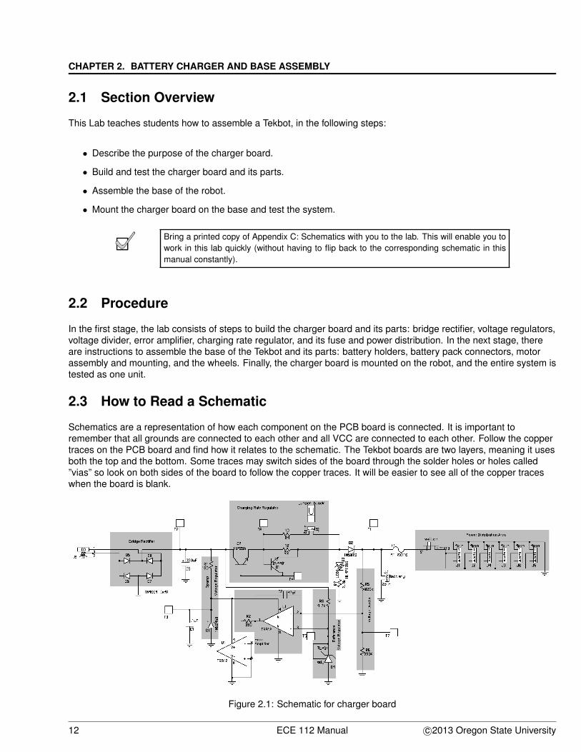
Schematics are a representation of how each component on the PCB board is connected. It is important toremember that all grounds are connected to each other and all VCC are connected to each other. Follow the coppertraces on the PCB board and find how it relates to the schematic. The Tekbot boards are two layers, meaning it usesboth the top and the bottom. Some traces may switch sides of the board through the solder holes or holes called”vias” so look on both sides of the board to follow the copper traces. It will be easier to see all of the copper traceswhen the board is blank.
Figure 2.1: Schematic for charger board
12 ECE 112 Manual c©2013 Oregon State University
2.4. BUILDING THE CHARGER BOARD
What is pin 1 of J9 of the charger board connected to?Where do the batteries get plugged into on the charger board?What is S1 and what does it do?
2.4 Building the Charger Board
The procedure for building the charger board parts is explained in the sub-sections: purpose, build, and test. Eachpart has been shaded respectively in the schematic diagram for the charger board, found in Appendix C:Schematics. The purpose sub-section explains why that part/shaded block is needed for the charger board. Thebuild sub-section describes the steps to build that portion of the circuit, as indicated in the shaded area of theSchematic. It also explains what supporting parts need to be soldered in. The test sub-section describes theprocess(es) necessary to test the block.
For complex systems such as the charger board, it is necessary to test each section assoon as it is built, so that errors are easily isolated. By building and testing each part insuccession and checking it for functionality, it is easy to isolate errors to the most recentlybuilt area.
2.4.1 Bridge Rectifier
Purpose:
There are basically three types of wall warts: the AC wall wart and two varieties of DC wall warts. The AC wall wartprovides an AC voltage at its output connector. The DC wall warts come in two varieties: with a positive center pinoutput connector, or with a negative center pin output connector. The bridge rectifier allows the charger board to useany of the above-mentioned wall warts without issues.
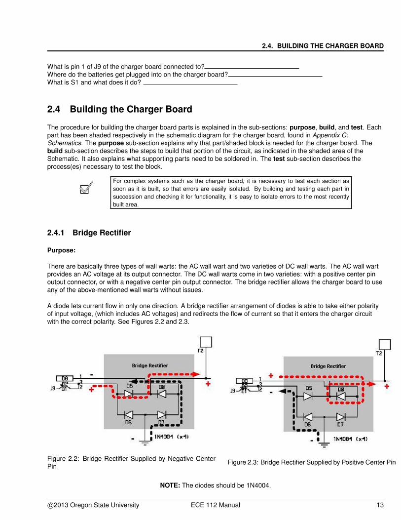
A diode lets current flow in only one direction. A bridge rectifier arrangement of diodes is able to take either polarityof input voltage, (which includes AC voltages) and redirects the flow of current so that it enters the charger circuitwith the correct polarity. See Figures 2.2 and 2.3.
Figure 2.2: Bridge Rectifier Supplied by Negative CenterPin
Figure 2.3: Bridge Rectifier Supplied by Positive Center Pin
NOTE: The diodes should be 1N4004.
c©2013 Oregon State University ECE 112 Manual 13
CHAPTER 2. BATTERY CHARGER AND BASE ASSEMBLY
If a component has polarity, it must be placed into the circuit in only one orientation or it willnot work correctly. Typically, most components will be instantly damaged if their polarity isnot observed. Diodes have the characteristic of polarity too. Diodes, however, are designedto pass current in one direction as well as to withstand substantial reverse voltage while notpassing any current.
Diodes allow current to flow from the anode to the cathode. The cathode is the sideof the diode with the band around it, (which indicates that current flows out of that end).
Build:
In order to build the bridge rectifier, read the following section Diode Placement Hint thoroughly. It will not only behelpful, but is also essential, before working on the next section Soldering the diodes.
Diode placement hint:
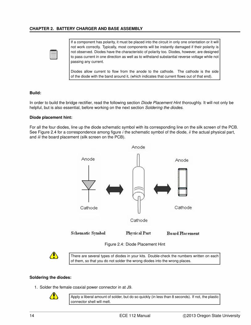
For all the four diodes, line up the diode schematic symbol with its corresponding line on the silk screen of the PCB.See Figure 2.4 for a correspondence among figure i the schematic symbol of the diode, ii the actual physical part,and iii the board placement (silk screen on the PCB).
Figure 2.4: Diode Placement Hint
There are several types of diodes in your kits. Double-check the numbers written on eachof them, so that you do not solder the wrong diodes into the wrong places.
Soldering the diodes:
1. Solder the female coaxial power connector in at J9.
Apply a liberal amount of solder, but do so quickly (in less than 8 seconds). If not, the plasticconnector shell will melt.
14 ECE 112 Manual c©2013 Oregon State University
2.4. BUILDING THE CHARGER BOARD
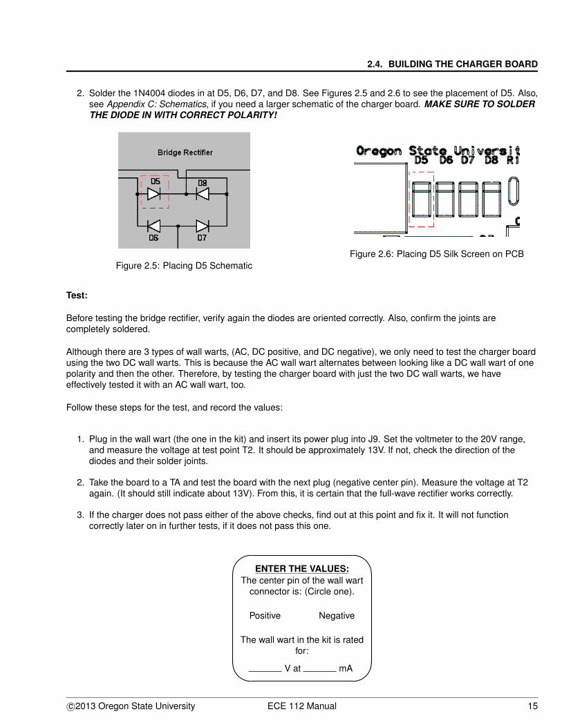
2. Solder the 1N4004 diodes in at D5, D6, D7, and D8. See Figures 2.5 and 2.6 to see the placement of D5. Also,see Appendix C: Schematics, if you need a larger schematic of the charger board. MAKE SURE TO SOLDERTHE DIODE IN WITH CORRECT POLARITY!
Figure 2.5: Placing D5 SchematicFigure 2.6: Placing D5 Silk Screen on PCB
Test:
Before testing the bridge rectifier, verify again the diodes are oriented correctly. Also, confirm the joints arecompletely soldered.
Although there are 3 types of wall warts, (AC, DC positive, and DC negative), we only need to test the charger boardusing the two DC wall warts. This is because the AC wall wart alternates between looking like a DC wall wart of onepolarity and then the other. Therefore, by testing the charger board with just the two DC wall warts, we haveeffectively tested it with an AC wall wart, too.
Follow these steps for the test, and record the values:
1. Plug in the wall wart (the one in the kit) and insert its power plug into J9. Set the voltmeter to the 20V range,and measure the voltage at test point T2. It should be approximately 13V. If not, check the direction of thediodes and their solder joints.
2. Take the board to a TA and test the board with the next plug (negative center pin). Measure the voltage at T2again. (It should still indicate about 13V). From this, it is certain that the full-wave rectifier works correctly.
3. If the charger does not pass either of the above checks, find out at this point and fix it. It will not functioncorrectly later on in further tests, if it does not pass this one.
'
&
$
%
ENTER THE VALUES:The center pin of the wall wart
connector is: (Circle one).
Positive Negative
The wall wart in the kit is ratedfor:
V at mA
c©2013 Oregon State University ECE 112 Manual 15
CHAPTER 2. BATTERY CHARGER AND BASE ASSEMBLY
TA Signature:(Bridge Rectifier Works)
2.4.2 Voltage Regulators
Purpose:
The op amp U1 keeps the chargers output voltage constant by comparing its output against a reference voltage. Itmust be powered with approximately 13V. The op amp also needs the reference voltage, which is 2.5V. A voltageregulator is therefore, a reliable way to obtain these two voltages.
Build
Use Appendix B: Parts List and Appendix C: Schematics to solder all of the parts needed for both: the voltageregulator and the reference voltage regulator.
To implement the above, follow these steps:
1. Solder in C3 and C1 before you build the reference and op amp voltage regulator. (C3 has polarity, but C1doesnt). Notice that C3 has minus signs on one side of it. Put the negative lead on that side into the hole that isconnected to ground. (Follow traces on the PCB).
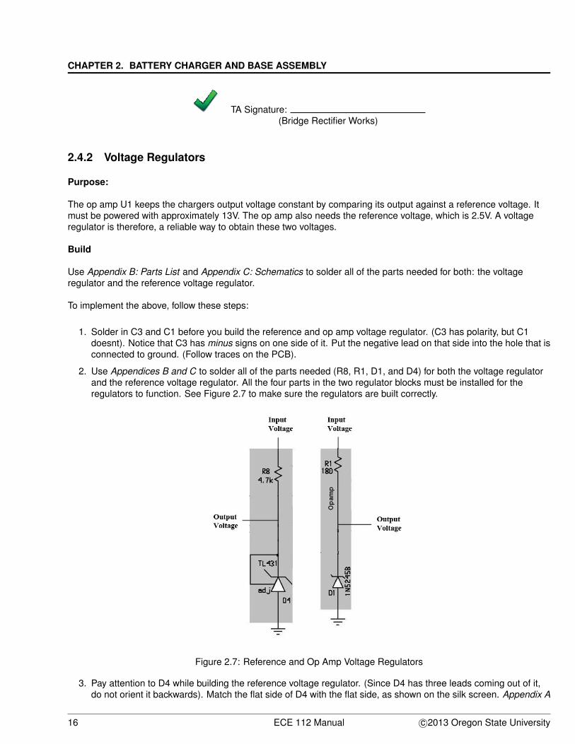
2. Use Appendices B and C to solder all of the parts needed (R8, R1, D1, and D4) for both the voltage regulatorand the reference voltage regulator. All the four parts in the two regulator blocks must be installed for theregulators to function. See Figure 2.7 to make sure the regulators are built correctly.
Figure 2.7: Reference and Op Amp Voltage Regulators
3. Pay attention to D4 while building the reference voltage regulator. (Since D4 has three leads coming out of it,do not orient it backwards). Match the flat side of D4 with the flat side, as shown on the silk screen. Appendix A
16 ECE 112 Manual c©2013 Oregon State University
2.4. BUILDING THE CHARGER BOARD
has a resistor color code chart to help find the correct resistors. You can double-check the resistor values usingthe DMM.
Test:
The 1N5245B will regulate at about 13V to supply the op amp with power. The TL431 provides a regulated referencevoltage of 2.5V to the op amp.
These regulators will be tested:
1. Plug in the wall wart and insert its power plug into J9.
2. Measure and record the voltage from Test Point T2 to ground. It should be about the same or (+/- 0.5V) fromwhat was previously measured.
3. Measure and record the voltage from T3 to ground. It should be 13V (+/- 1.0V).
4. Measure and record the voltage from T5 to ground. It should be 2.5V (+/- 100mV).
5. If either voltage regulator does not pass all of the above checks, find out at this point and fix it. Not only will itnot function correctly later, but other parts will be damaged too.
'
&
$
%
ENTER THE VALUES:
Voltage T2: V
Voltage T3: V
Voltage T5: V
2.4.3 Voltage Divider, Error Amplifier, and Charging Rate Regulator
Voltage Divider
The charger seeks to maintain 8.7V at its output terminal. This is the voltage of a fully charged battery pack. Thevoltage divider multiplies the output voltage by 0.286. When the output voltage is 8.7V, the input to the op amp is2.5V (that is, 0.286 x 8.7V).
Error Amplifier
The op amp acts as an error amplifier that senses the difference between the 2.5V reference and the divided-downvoltage at T7. If T7 is lower than 2.5V, then the error amplifier output increases its output voltage. If T7 is higher than2.5V, the amplifier output is reduced.
Charging Rate Regulator
The rate regulator acts as the valve controlled by the error amplifier to charge the batteries at a higher or lowervoltage, as dictated by the error amplifier. This valve is needed to allow for the larger amounts of current required forcharging the batteries.
c©2013 Oregon State University ECE 112 Manual 17
CHAPTER 2. BATTERY CHARGER AND BASE ASSEMBLY
Build:
The integrated circuit (IC) U1 has polarity. To implement the above, follow these steps:
1. Match the side of the chip with the half-circle onto the silkscreen with the same half-circle. As Q1 and Q2 bothhave polarity, work with caution.
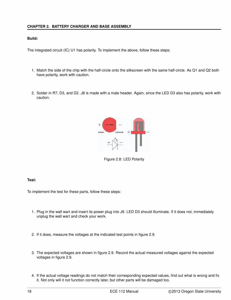
2. Solder in R7, D3, and D2. J8 is made with a male header. Again, since the LED D3 also has polarity, work withcaution.
Figure 2.8: LED Polarity
Test:
To implement the test for these parts, follow these steps:
1. Plug in the wall wart and insert its power plug into J9. LED D3 should illuminate. If it does not, immediatelyunplug the wall wart and check your work.
2. If it does, measure the voltages at the indicated test points in figure 2.9.
3. The expected voltages are shown in figure 2.9. Record the actual measured voltages against the expectedvoltages in figure 2.9.
4. If the actual voltage readings do not match their corresponding expected values, find out what is wrong and fixit. Not only will it not function correctly later, but other parts will be damaged too.
18 ECE 112 Manual c©2013 Oregon State University

2.4. BUILDING THE CHARGER BOARD
Figure 2.9: Voltage Readings
2.4.4 Fuse and Power Distribution
Purpose:
Every electrical system has to be powered by a source. Connectors provide the mechanical mechanism to do this.The connectors primarily used on the TekBot are 0.1” socketed headers. This type of connector is common,inexpensive, and is available in many configurations. It works well especially when the connectors need to beinserted and removed many times over the life of the circuit.
Build:
In order to build the external connectors, follow these steps:
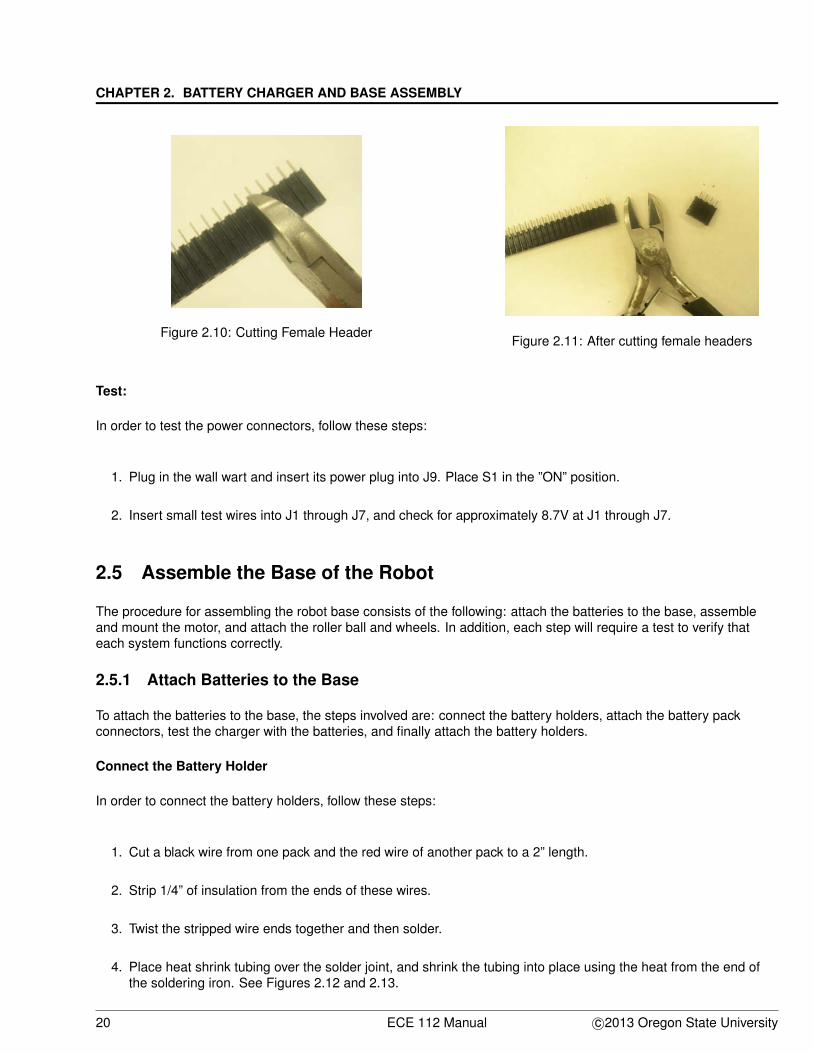
1. J1 to J7 are female connectors. Create these by ’snapping them off’ of the long sections of the female headerin the kit.
2. Snap one of the positions in-half so the other connectors are complete and not damaged. See Figures 2.10and 2.11.
3. Solder in the fuse F1 and the switch S1.
c©2013 Oregon State University ECE 112 Manual 19
CHAPTER 2. BATTERY CHARGER AND BASE ASSEMBLY
Figure 2.10: Cutting Female HeaderFigure 2.11: After cutting female headers
Test:
In order to test the power connectors, follow these steps:
1. Plug in the wall wart and insert its power plug into J9. Place S1 in the ”ON” position.
2. Insert small test wires into J1 through J7, and check for approximately 8.7V at J1 through J7.
2.5 Assemble the Base of the Robot
The procedure for assembling the robot base consists of the following: attach the batteries to the base, assembleand mount the motor, and attach the roller ball and wheels. In addition, each step will require a test to verify thateach system functions correctly.
2.5.1 Attach Batteries to the Base
To attach the batteries to the base, the steps involved are: connect the battery holders, attach the battery packconnectors, test the charger with the batteries, and finally attach the battery holders.
Connect the Battery Holder
In order to connect the battery holders, follow these steps:
1. Cut a black wire from one pack and the red wire of another pack to a 2” length.
2. Strip 1/4” of insulation from the ends of these wires.
3. Twist the stripped wire ends together and then solder.
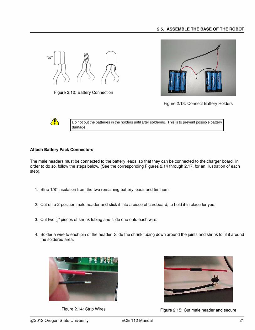
4. Place heat shrink tubing over the solder joint, and shrink the tubing into place using the heat from the end ofthe soldering iron. See Figures 2.12 and 2.13.
20 ECE 112 Manual c©2013 Oregon State University
2.5. ASSEMBLE THE BASE OF THE ROBOT
Figure 2.12: Battery Connection
Figure 2.13: Connect Battery Holders
Do not put the batteries in the holders until after soldering. This is to prevent possible batterydamage.
Attach Battery Pack Connectors
The male headers must be connected to the battery leads, so that they can be connected to the charger board. Inorder to do so, follow the steps below. (See the corresponding Figures 2.14 through 2.17, for an illustration of eachstep).
1. Strip 1/8” insulation from the two remaining battery leads and tin them.
2. Cut off a 2-position male header and stick it into a piece of cardboard, to hold it in place for you.
3. Cut two 14 ” pieces of shrink tubing and slide one onto each wire.
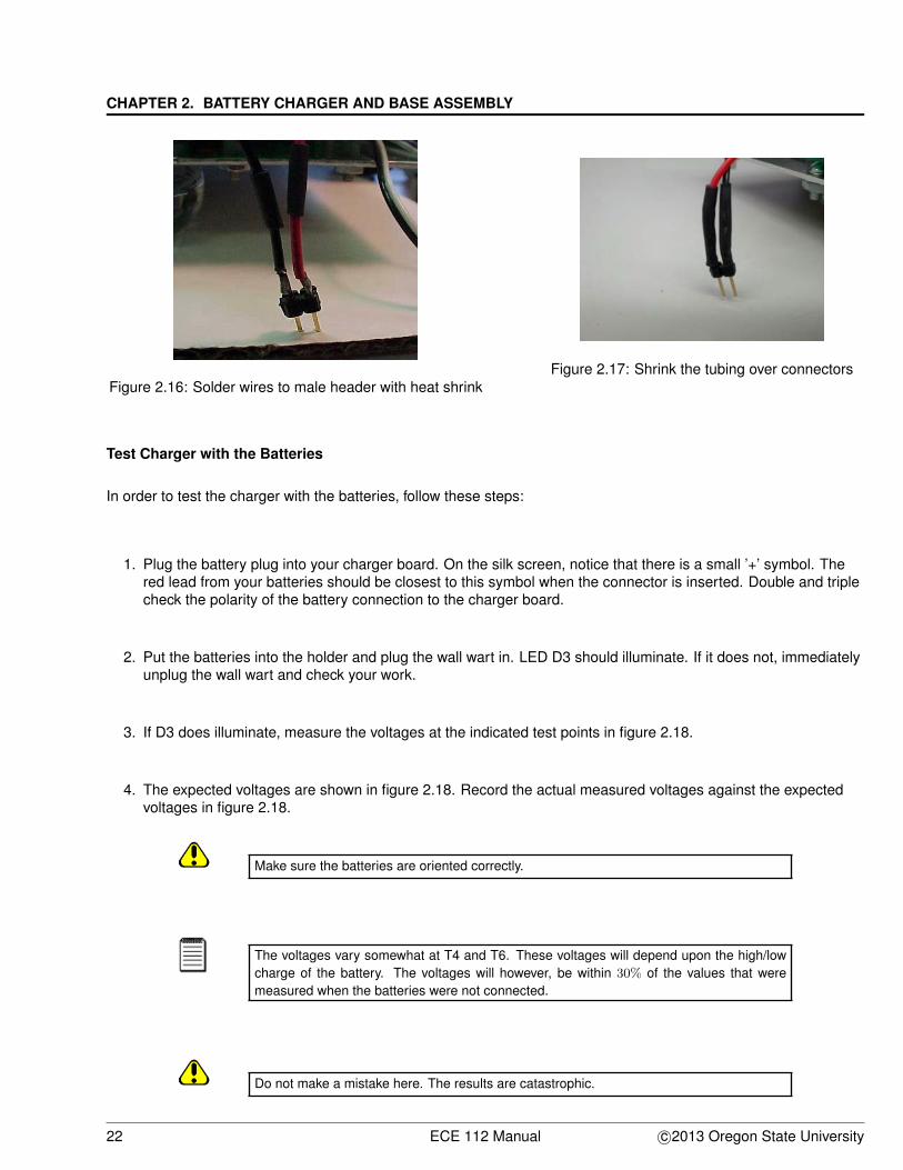
4. Solder a wire to each pin of the header. Slide the shrink tubing down around the joints and shrink to fit it aroundthe soldered area.
Figure 2.14: Strip Wires Figure 2.15: Cut male header and secure
c©2013 Oregon State University ECE 112 Manual 21
CHAPTER 2. BATTERY CHARGER AND BASE ASSEMBLY
Figure 2.16: Solder wires to male header with heat shrinkFigure 2.17: Shrink the tubing over connectors
Test Charger with the Batteries
In order to test the charger with the batteries, follow these steps:
1. Plug the battery plug into your charger board. On the silk screen, notice that there is a small ’+’ symbol. Thered lead from your batteries should be closest to this symbol when the connector is inserted. Double and triplecheck the polarity of the battery connection to the charger board.
2. Put the batteries into the holder and plug the wall wart in. LED D3 should illuminate. If it does not, immediatelyunplug the wall wart and check your work.
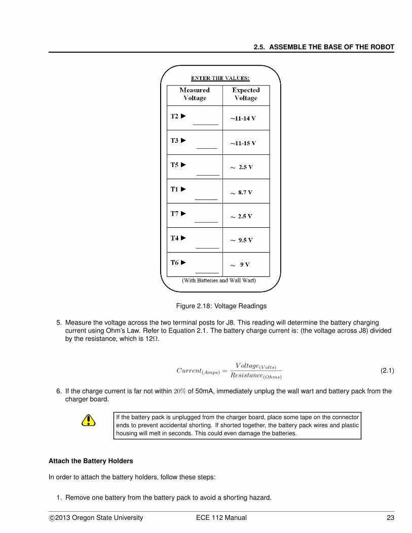
3. If D3 does illuminate, measure the voltages at the indicated test points in figure 2.18.
4. The expected voltages are shown in figure 2.18. Record the actual measured voltages against the expectedvoltages in figure 2.18.
Make sure the batteries are oriented correctly.
The voltages vary somewhat at T4 and T6. These voltages will depend upon the high/lowcharge of the battery. The voltages will however, be within 30% of the values that weremeasured when the batteries were not connected.
Do not make a mistake here. The results are catastrophic.
22 ECE 112 Manual c©2013 Oregon State University
2.5. ASSEMBLE THE BASE OF THE ROBOT
Figure 2.18: Voltage Readings
5. Measure the voltage across the two terminal posts for J8. This reading will determine the battery chargingcurrent using Ohm’s Law. Refer to Equation 2.1. The battery charge current is: (the voltage across J8) dividedby the resistance, which is 12Ω.
Current(Amps) =V oltage(V olts)
Resistance(Ohms)(2.1)
6. If the charge current is far not within 20% of 50mA, immediately unplug the wall wart and battery pack from thecharger board.
If the battery pack is unplugged from the charger board, place some tape on the connectorends to prevent accidental shorting. If shorted together, the battery pack wires and plastichousing will melt in seconds. This could even damage the batteries.
Attach the Battery Holders
In order to attach the battery holders, follow these steps:
1. Remove one battery from the battery pack to avoid a shorting hazard.
c©2013 Oregon State University ECE 112 Manual 23
CHAPTER 2. BATTERY CHARGER AND BASE ASSEMBLY
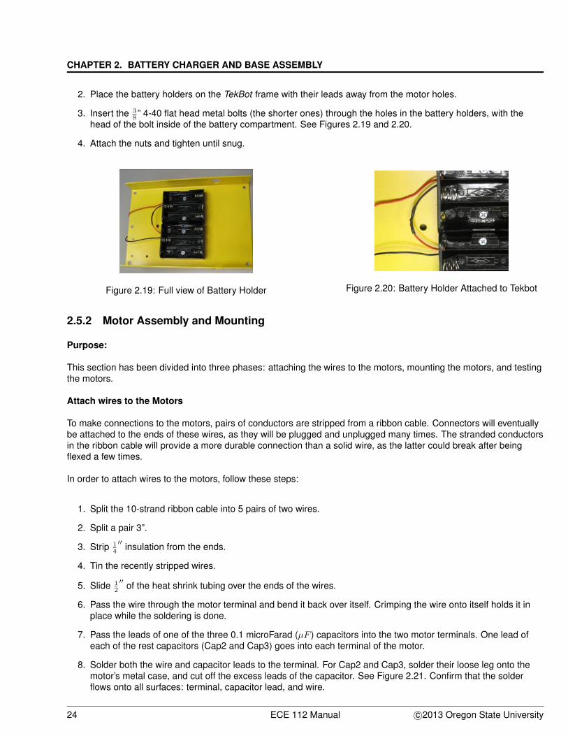
2. Place the battery holders on the TekBot frame with their leads away from the motor holes.
3. Insert the 38 ” 4-40 flat head metal bolts (the shorter ones) through the holes in the battery holders, with the
head of the bolt inside of the battery compartment. See Figures 2.19 and 2.20.
4. Attach the nuts and tighten until snug.
Figure 2.19: Full view of Battery Holder Figure 2.20: Battery Holder Attached to Tekbot
2.5.2 Motor Assembly and Mounting
Purpose:
This section has been divided into three phases: attaching the wires to the motors, mounting the motors, and testingthe motors.
Attach wires to the Motors
To make connections to the motors, pairs of conductors are stripped from a ribbon cable. Connectors will eventuallybe attached to the ends of these wires, as they will be plugged and unplugged many times. The stranded conductorsin the ribbon cable will provide a more durable connection than a solid wire, as the latter could break after beingflexed a few times.
In order to attach wires to the motors, follow these steps:
1. Split the 10-strand ribbon cable into 5 pairs of two wires.
2. Split a pair 3”.
3. Strip 14
′′ insulation from the ends.
4. Tin the recently stripped wires.
5. Slide 12
′′ of the heat shrink tubing over the ends of the wires.
6. Pass the wire through the motor terminal and bend it back over itself. Crimping the wire onto itself holds it inplace while the soldering is done.
7. Pass the leads of one of the three 0.1 microFarad (µF ) capacitors into the two motor terminals. One lead ofeach of the rest capacitors (Cap2 and Cap3) goes into each terminal of the motor.
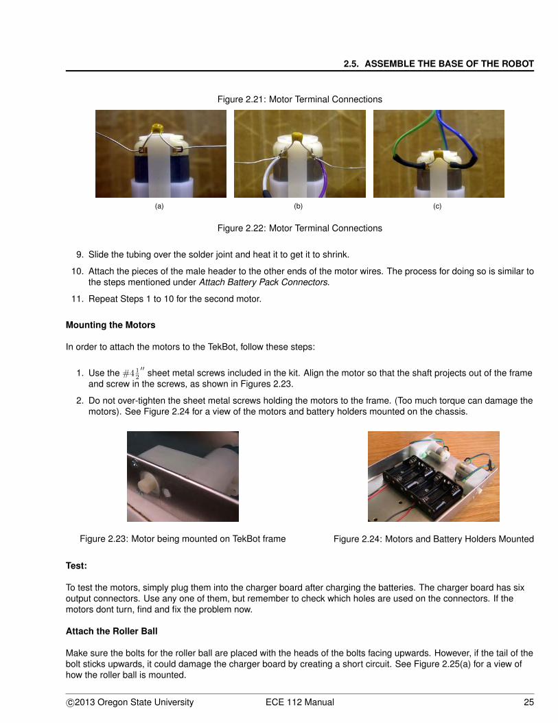
8. Solder both the wire and capacitor leads to the terminal. For Cap2 and Cap3, solder their loose leg onto themotor’s metal case, and cut off the excess leads of the capacitor. See Figure 2.21. Confirm that the solderflows onto all surfaces: terminal, capacitor lead, and wire.
24 ECE 112 Manual c©2013 Oregon State University
2.5. ASSEMBLE THE BASE OF THE ROBOT
Figure 2.21: Motor Terminal Connections
(a) (b) (c)
Figure 2.22: Motor Terminal Connections
9. Slide the tubing over the solder joint and heat it to get it to shrink.
10. Attach the pieces of the male header to the other ends of the motor wires. The process for doing so is similar tothe steps mentioned under Attach Battery Pack Connectors.
11. Repeat Steps 1 to 10 for the second motor.
Mounting the Motors
In order to attach the motors to the TekBot, follow these steps:
1. Use the #4 12
′′ sheet metal screws included in the kit. Align the motor so that the shaft projects out of the frameand screw in the screws, as shown in Figures 2.23.
2. Do not over-tighten the sheet metal screws holding the motors to the frame. (Too much torque can damage themotors). See Figure 2.24 for a view of the motors and battery holders mounted on the chassis.
Figure 2.23: Motor being mounted on TekBot frame Figure 2.24: Motors and Battery Holders Mounted
Test:
To test the motors, simply plug them into the charger board after charging the batteries. The charger board has sixoutput connectors. Use any one of them, but remember to check which holes are used on the connectors. If themotors dont turn, find and fix the problem now.
Attach the Roller Ball
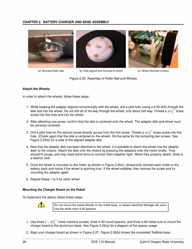
Make sure the bolts for the roller ball are placed with the heads of the bolts facing upwards. However, if the tail of thebolt sticks upwards, it could damage the charger board by creating a short circuit. See Figure 2.25(a) for a view ofhow the roller ball is mounted.
c©2013 Oregon State University ECE 112 Manual 25
CHAPTER 2. BATTERY CHARGER AND BASE ASSEMBLY
(a) Mounted Roller Ball (b) Disk aligned and mounted to wheel (c) Wheel Mounted to Motor
Figure 2.25: Assembly of Roller Ball and Wheels
Attach the Wheels
In order to attach the wheels, follow these steps:
1. While keeping the adapter aligned concentrically with the wheel, drill a pilot hole (using a # 50 drill) through thedisk and into the wheel. Do not drill all of the way through the wheel, only about half way. Thread a #2 1
2
′′ brassscrew into this hole and into the wheel.
2. After attaching one screw, confirm that the disk is centered onto the wheel. The adapter disk and wheel mustbe correctly centered.
3. Drill a pilot hole for the second screw directly across from the first screw. Thread a #2 12
′′ brass screw into thishole. (Check again that the disk is centered on the wheel). Do the same for the remaining two screws. SeeFigure 2.25(b) for a view of the aligned adapter disk.
4. Now that the adapter disk has been attached to the wheel, it is possible to attach the wheel (via the adapterdisk) to the motors. Attach the disk onto the motors by pressing the adapters onto the motor shafts. Theyshould fit snugly, and may need some force to connect them together tight. When they properly attach, there isa distinct click.
5. Once the wheel is mounted on the motor as shown in Figure 2.25(c), temporarily connect each motor to thebattery pack and notice if the wheel is spinning true. If the wheel wobbles, then remove the screw and trymounting the adapter again.
6. Repeat Steps 1 to 5 for other wheel.
Mounting the Charger Board on the Robot
To implement the above, follow these steps:
Do not mount the board directly to the metal base, or severe electrical damage will occur.Use the white nylon 4-40 spacers.
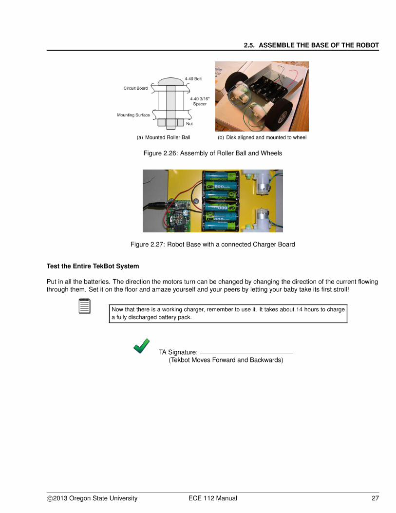
1. Use three 4 − 40 12
′′ metal machine screws, three 4-40 round spacers, and three 4-40 metal nuts to mount thecharger board to the aluminium base. See Figure 2.26(a) for a diagram of the spacer usage.
2. Align your charger board as shown in Figure 2.27. Figure 2.26(b) shows the completed TekBots base.
26 ECE 112 Manual c©2013 Oregon State University
2.5. ASSEMBLE THE BASE OF THE ROBOT
(a) Mounted Roller Ball (b) Disk aligned and mounted to wheel
Figure 2.26: Assembly of Roller Ball and Wheels
Figure 2.27: Robot Base with a connected Charger Board
Test the Entire TekBot System
Put in all the batteries. The direction the motors turn can be changed by changing the direction of the current flowingthrough them. Set it on the floor and amaze yourself and your peers by letting your baby take its first stroll!
Now that there is a working charger, remember to use it. It takes about 14 hours to chargea fully discharged battery pack.
TA Signature:(Tekbot Moves Forward and Backwards)
c©2013 Oregon State University ECE 112 Manual 27
CHAPTER 2. BATTERY CHARGER AND BASE ASSEMBLY
2.6 Study Questions
1. As was mentioned earlier, a diode only lets current flow in one direction. Why do you think that the diode D2was included in the charger circuit? What problem(s) do you think, may occur, if it was excluded from thecircuit?
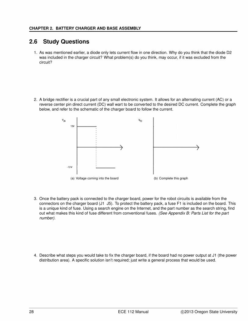
2. A bridge rectifier is a crucial part of any small electronic system. It allows for an alternating current (AC) or areverse center pin direct current (DC) wall wart to be converted to the desired DC current. Complete the graphbelow, and refer to the schematic of the charger board to follow the current.
(a) Voltage coming into the board (b) Complete this graph
3. Once the battery pack is connected to the charger board, power for the robot circuits is available from theconnectors on the charger board (J1 J5). To protect the battery pack, a fuse F1 is included on the board. Thisis a unique kind of fuse. Using a search engine on the Internet, and the part number as the search string, findout what makes this kind of fuse different from conventional fuses. (See Appendix B: Parts List for the partnumber).
4. Describe what steps you would take to fix the charger board, if the board had no power output at J1 (the powerdistribution area). A specific solution isn’t required; just write a general process that would be used.
28 ECE 112 Manual c©2013 Oregon State University
2.6. STUDY QUESTIONS
2.6.1 Challenge
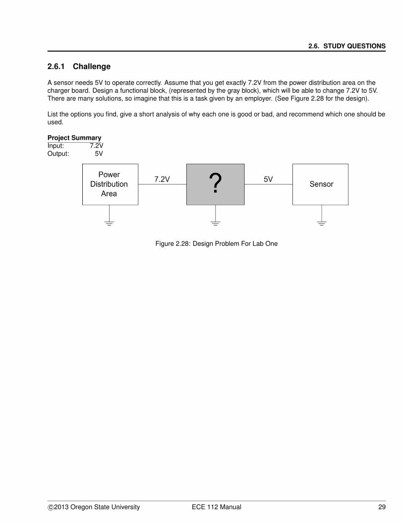
A sensor needs 5V to operate correctly. Assume that you get exactly 7.2V from the power distribution area on thecharger board. Design a functional block, (represented by the gray block), which will be able to change 7.2V to 5V.There are many solutions, so imagine that this is a task given by an employer. (See Figure 2.28 for the design).
List the options you find, give a short analysis of why each one is good or bad, and recommend which one should beused.
Project SummaryInput: 7.2VOutput: 5V
Figure 2.28: Design Problem For Lab One
c©2013 Oregon State University ECE 112 Manual 29
CHAPTER 2. BATTERY CHARGER AND BASE ASSEMBLY
30 ECE 112 Manual c©2013 Oregon State University


