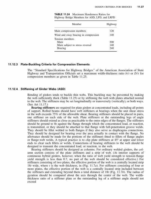
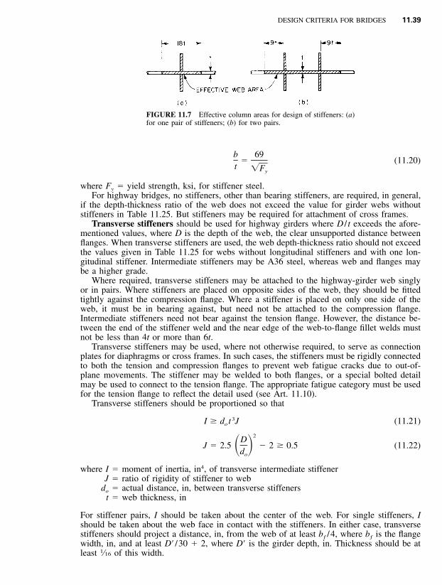
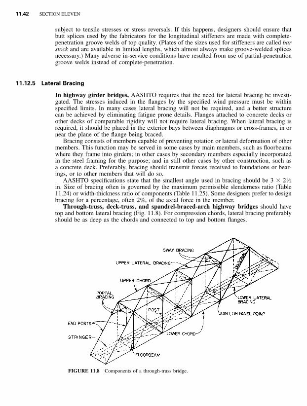
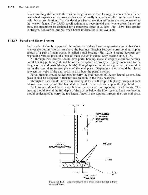
11.1 SECTION 11 DESIGN CRITERIA FOR BRIDGES PART 1 APPLICATION OF CRITERIA FOR COST-EFFECTIVE HIGHWAY BRIDGE DESIGN Robert L. Nickerson,* P.E. President, NBE, Ltd., Hampstead, Maryland Dennis Mertz,* P.E. Assoc. Professor of Civil Engineering, University of Delaware, Newark, Delaware The purpose of this section is to provide guidance to highway bridge designers for application of standard design specifications to the more common types of bridges and to provide rules of thumb to assist in obtaining cost-effective and safe structures. Because of the complexity of modern specifications for bridge design and construction and the large number of standards and guides with which designers must be familiar to ensure adequate designs, this section does not provide comprehensive treatment of all types of bridges. Because specifications are continually being revised, readers are cautioned to use the latest edition, including interims, in practical applications. 11.1 STANDARD SPECIFICATIONS Designs for most highway bridges in the United States are governed by the ‘‘Standard Spec- ifications for Highway Bridges’’ or the ‘‘LRFD Bridge Design Specifications’’of the Amer- ican Association of State Highway and Transportation Officials (AASHTO), 444 N. Capitol St., NW, Washington, DC 20001. AASHTO updates these specifications annually. Necessary revisions are published as ‘‘Interim Specifications.’’A new edition of the Standard Specifi- cations has been published about every fourth year, incorporating intervening ‘‘Interim Spec- *Revised Sec. 10, originally written by Frank D. Sears, Bridge Division, Federal Highway Administration, Wash- ington, D.C. Material on ASD and LFD design was updated by Roger L. Brockenbrough.
Transcript
11.1
SECTION 11DESIGN CRITERIA FOR BRIDGES
PART 1
APPLICATION OF CRITERIA FOR COST-EFFECTIVEHIGHWAY BRIDGE DESIGN
Robert L. Nickerson,* P.E.President, NBE, Ltd.,Hampstead, Maryland
Dennis Mertz,* P.E.Assoc. Professor of Civil Engineering,University of Delaware,Newark, Delaware
The purpose of this section is to provide guidance to highway bridge designers for applicationof standard design specifications to the more common types of bridges and to provide rulesof thumb to assist in obtaining cost-effective and safe structures. Because of the complexityof modern specifications for bridge design and construction and the large number of standardsand guides with which designers must be familiar to ensure adequate designs, this sectiondoes not provide comprehensive treatment of all types of bridges. Because specifications arecontinually being revised, readers are cautioned to use the latest edition, including interims,in practical applications.
11.1 STANDARD SPECIFICATIONS
Designs for most highway bridges in the United States are governed by the ‘‘Standard Spec-ifications for Highway Bridges’’ or the ‘‘LRFD Bridge Design Specifications’’ of the Amer-ican Association of State Highway and Transportation Officials (AASHTO), 444 N. CapitolSt., NW, Washington, DC 20001. AASHTO updates these specifications annually. Necessaryrevisions are published as ‘‘Interim Specifications.’’ A new edition of the Standard Specifi-cations has been published about every fourth year, incorporating intervening ‘‘Interim Spec-
* Revised Sec. 10, originally written by Frank D. Sears, Bridge Division, Federal Highway Administration, Wash-ington, D.C. Material on ASD and LFD design was updated by Roger L. Brockenbrough.
11.2 SECTION ELEVEN
ifications.’’ The design criteria for highway bridges in this section are based on the 16th(1996) edition of the Standard Specifications, with 1997 and 1998 Interims, and the 2nd(1998) edition of the LRFD Specifications. Current plans of AASHTO are to discontinuemaintenance of the Standard Specifications and to emphasize the LRFD Specifications. Acomplete design example for a two-span continuous I-girder bridge is included as an Ap-pendix to this section to illustrate application of the LRFD Specifications.
For complex design-related items or modifications involving new technology, AASHTOissues tentative ‘‘Guide Specifications,’’ to allow further assessment and refinement of thenew criteria. AASHTO may adopt a ‘‘Guide Specification,’’ after a trial period of use, aspart of the Standard Specifications.
State highway departments usually adopt the AASHTO bridge specifications as their min-imum standards for highway bridge design. Because conditions vary from state to state,however, many bridge owners modify the standard specifications to meet specific needs. Forexample, California has specific requirements for earthquake resistance that may not beappropriate for many east-coast structures.
To ensure safe, cost-effective, and durable structures, designers should meet the require-ments of the latest specifications and guides available. For unusual types of structures, orfor bridges with spans longer than about 500 ft, designers should make a more detailedapplication of theory and performance than is possible with standard criteria or the practicesdescribed in this section. Use of much of the standard specifications, however, is appropriatefor unusual structures, inasmuch as these generally are composed of components to whichthe specifications are applicable.
11.2 DESIGN METHODS
AASHTO ‘‘Standard Specifications for Highway Bridges’’ present two design methods forsteel bridges: service-load, or allowable-stress, design (ASD) and strength, or load-factor,design (LFD). Both are being replaced by load-and-resistance-factor design (LRFD). TheLRFD Specifications utilize factors based on the theory of reliability and statistical knowl-edge of load and material characteristics. (See also Sec. 6.) It identifies methods of modelingand analysis. It incorporates many of the existing AASHTO ‘‘Guide Specifications.’’ Also,it includes features that are equally applicable to ASD and LFD that are not in the StandardSpecifications. For example, the LRFD specifications include serviceability requirements fordurability of bridge materials, inspectability of bridge components, maintenance that includesdeck-replacement considerations in adverse environments, constructability, ridability, econ-omy, and esthetics. Although procedures for ASD are presented in many of the followingarticles, LFD or LRFD may often yield more economical results. A structure designed byLRFD methods will be better proportioned, with all parts of the structure theoretically de-signed for the same degree of reliability.
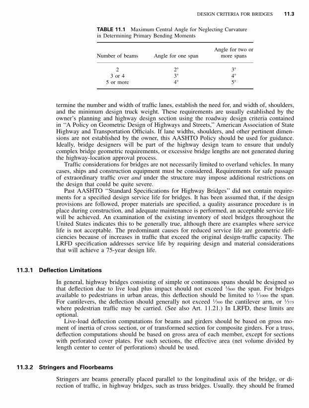
Curved girders are not fully covered by the LRFD Specifications, and were not a part ofthe calibration data base. The LRFD Specification does allow girders with slight curvaturesto be designed as if they are straight. Specifically, it is permitted for ‘‘torsionally stiff closedsections whose central angle subtended by a curved span . . . is less than 12.0�.’’ and for‘‘open sections whose radius is such that the central angle subtended by each span is lessthan the value given in’’ Table 11.1. For the design of bridges with greater curvatures, referto the AASHTO ‘‘Guide Specifications for Horizontally Curved Highway Bridges,’’ includingthe latest Interim Specifications. Also see Arts. 12.6 and 12.7. Current research may sub-stantially modify these criteria in the future.
11.3 PRIMARY DESIGN CONSIDERATIONS
The primary purpose of a highway bridge is to safely carry (geometrically and structurally)the necessary traffic volumes and loads. Normally, traffic volumes, present and future, de-
DESIGN CRITERIA FOR BRIDGES 11.3
TABLE 11.1 Maximum Central Angle for Neglecting Curvaturein Determining Primary Bending Moments
Number of beams Angle for one spanAngle for two or
more spans
2 2� 3�3 or 4 3� 4�
5 or more 4� 5�
termine the number and width of traffic lanes, establish the need for, and width of, shoulders,and the minimum design truck weight. These requirements are usually established by theowner’s planning and highway design section using the roadway design criteria containedin ‘‘A Policy on Geometric Design of Highways and Streets,’’ American Association of StateHighway and Transportation Officials. If lane widths, shoulders, and other pertinent dimen-sions are not established by the owner, this AASHTO Policy should be used for guidance.Ideally, bridge designers will be part of the highway design team to ensure that undulycomplex bridge geometric requirements, or excessive bridge lengths are not generated duringthe highway-location approval process.
Traffic considerations for bridges are not necessarily limited to overland vehicles. In manycases, ships and construction equipment must be considered. Requirements for safe passageof extraordinary traffic over and under the structure may impose additional restrictions onthe design that could be quite severe.
Past AASHTO ‘‘Standard Specifications for Highway Bridges’’ did not contain require-ments for a specified design service life for bridges. It has been assumed that, if the designprovisions are followed, proper materials are specified, a quality assurance procedure is inplace during construction, and adequate maintenance is performed, an acceptable service lifewill be achieved. An examination of the existing inventory of steel bridges throughout theUnited States indicates this to be generally true, although there are examples where servicelife is not acceptable. The predominant causes for reduced service life are geometric defi-ciencies because of increases in traffic that exceed the original design-traffic capacity. TheLRFD specification addresses service life by requiring design and material considerationsthat will achieve a 75-year design life.
11.3.1 Deflection Limitations
In general, highway bridges consisting of simple or continuous spans should be designed sothat deflection due to live load plus impact should not exceed 1⁄800 the span. For bridgesavailable to pedestrians in urban areas, this deflection should be limited to 1⁄1000 the span.For cantilevers, the deflection should generally not exceed 1⁄300 the cantilever arm, or 1⁄375
where pedestrian traffic may be carried. (See also Art. 11.21.) In LRFD, these limits areoptional.
Live-load deflection computations for beams and girders should be based on gross mo-ment of inertia of cross section, or of transformed section for composite girders. For a truss,deflection computations should be based on gross area of each member, except for sectionswith perforated cover plates. For such sections, the effective area (net volume divided bylength center to center of perforations) should be used.
11.3.2 Stringers and Floorbeams
Stringers are beams generally placed parallel to the longitudinal axis of the bridge, or di-rection of traffic, in highway bridges, such as truss bridges. Usually. they should be framed
11.4 SECTION ELEVEN
into floorbeams. But if they are supported on the top flanges of the floorbeams, it is desirablethat the stringers he continuous over two or more panels. In bridges with wood floors,intermediate cross frames or diaphragms should be placed between stringers more than 20ft long.
In skew bridges without end floorbeams, the stringers, at the end bearings, should be heldin correct position by end struts also connected to the main trusses or girders. Lateral bracingin the end panels should be connected to the end struts and main trusses or girders.
Floorbeams preferably should be perpendicular to main trusses or girders. Also, connec-tions to those members should be positioned to permit attachment of lateral bracing, ifrequired, to both floorbeam and main truss or girder.
Main material of floorbeam hangers should not be coped or notched. Built-up hangersshould have solid or perforated web plates or lacing.
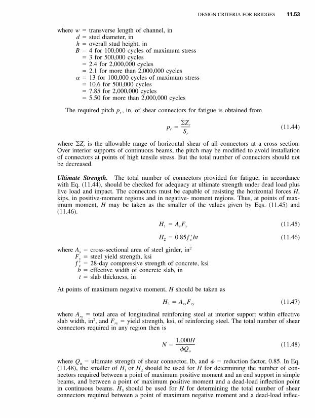
11.4 HIGHWAY DESIGN LOADINGS
The AASHTO ‘‘Standard Specifications for Highway Bridges’’ require bridges to be designedto carry dead and live loads and impact, or the dynamic effect of the live load. Structuresshould also be capable of sustaining other loads to which they may be subjected, such aslongitudinal, centrifugal, thermal, seismic, and erection forces. Various combinations of theseloads must be considered as designated in groups I through X. (See Art. 11.5.1.)
The LRFD Specification separates loads into two categories: permanent and transient. Thefollowing are the loads to be considered and their designation (load combinations are dis-cussed in Art. 11.5.4):
Permanent Loads
DD � downdragDC � dead load of structural components and nonstructural attachmentsDW � dead load of wearing surfaces and utilitiesEH � horizontal earth pressure loadEL � accumulated locked-in force effects resulting from constructionES � earth surcharge loadEV � vertical pressure from dead load of earth fill
LS � live load surchargePL � pedestrian live loadSE � settlementSH � shrinkageTG � temperature gradientTU � uniform temperatureWA � water load and stream pressureWL � wind on live loadWS � wind load on structure
Certain loads applicable to the design of superstructures of steel beam/girder-slab bridgesare discussed in detail below.
Dead Loads. Designers should use the actual dead weights of materials specified for thestructure. For the more commonly used materials, the AASHTO Specifications provide theweights to be used. For other materials, designers must determine the proper design loads.It is important that the dead loads used in design be noted on the contract plans for analysispurposes during possible future rehabilitations.
Live Loads. There are four standard classes of highway vehicle loadings included in theStandard Specifications: H15, H20, HS15, and HS20. The AASHTO ‘‘Geometric Guide’’states that the minimum design loading for new bridges should be HS20 (Fig. 11.l) for allfunctional classes (local roads through freeways) of highways. Therefore, most bridge ownersrequire design for HS20 truck loadings or greater. AASHTO also specifies an alternativetandem loading of two 25-kip axles spaced 4 ft c to c.
The difference in truck gross weights is a direct ratio of the HS number; e.g., HS15 is75% of HS20. (The difference between the H and HS trucks is the use of a third axle onan HS truck.) Many bridge owners, recognizing the trucking industries’ use of heavier ve-hicles, are specifying design loadings greater than HS20.
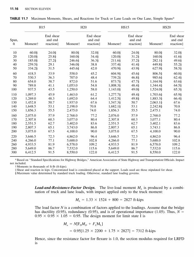
For longer-span bridges, lane loadings are used to simulate multiple vehicles in a givenlane. For example, for HS20 loading on a simple span, the lane load is 0.64 kips per ft plusan 18-kip concentrated load for moment or a 26-kip load for shear. A simple-span girderbridge with a span longer than about 140 ft would be subjected to a greater live-load designmoment for the lane loading than for the truck loading (Table 11.7). (For end shear andreaction, the breakpoint is about 120 ft). Truck and lane loadings are not applied concurrentlyfor ASD or LFD.
In ASD and LFD, if maximum stresses are induced in a member by loading of more thantwo lanes, the live load for three lanes should be reduced by 10%, and for four or morelanes, 25%. For LRFD, a reduction or increase depends on the method for live-load distri-bution.
For LRFD, the design vehicle design load is a combination of truck (or tandem) and laneloads and differs for positive and negative moment. Figure 11.2 shows the governing liveloads for LRFD to produce maximum moment in a beam. The vehicular design live loadingis one of the major differences in the LRFD Specification. Through statistical analysis ofexisting highway loadings, and their effect on highway bridges, a combination of the designtruck, or design tandem (intended primarily for short spans), and the design lane load, con-stitutes the HL-93 design live load for LRFD. As in previous specifications, this loadingoccupies a 10 ft width of a design lane. Depending upon the number of design lanes on thebridge, the possibility of more than one truck being on the bridge must be considered. Theeffects of the HL-93 loading should be factored by the multiple presence factor (see Table
11.6 SECTION ELEVEN
FIGURE 11.1 Standard HS loadings for design of highway bridges. Truck loading forASD and LFD. W is the combined weight of the first two axles. V is the spacing of theaxles, between 14 and 30 ft, inclusive, that produces maximum stresses.
11.2). However, the multiple presence factor should not to be applied for fatigue calculations,or when the subsequently discussed approximate live load distribution factors are used.
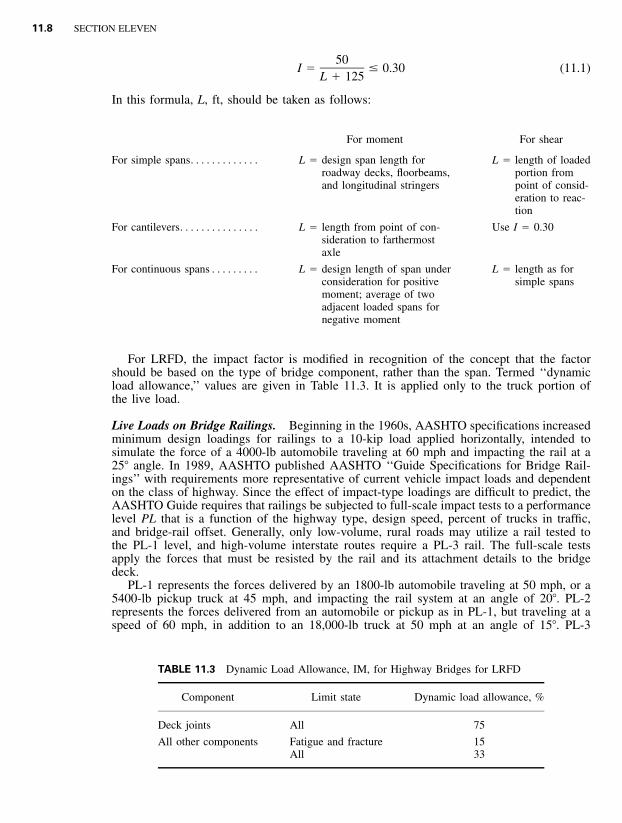
Impact. A factor is applied to vehicular live loads to represent increases in loading due toimpact caused by a rough roadway surface or other disturbance. In the AASHTO StandardSpecifications, the impact factor I is a function of span and is determined from
DESIGN CRITERIA FOR BRIDGES 11.7
FIGURE 11.2 Loadings for maximum moment and reaction for LRFDdesign of highway bridges.
TABLE 11.2 Multiple Presence Factors
Number of loaded lanes Multiple presence factor, m
1 1.202 1.003 0.85
�3 0.65
11.8 SECTION ELEVEN
TABLE 11.3 Dynamic Load Allowance, IM, for Highway Bridges for LRFD
Component Limit state Dynamic load allowance, %
Deck joints All 75
All other components Fatigue and fractureAll
1533
50I � � 0.30 (11.1)
L � 125
In this formula, L, ft, should be taken as follows:
L � length of loadedportion frompoint of consid-eration to reac-tion
For cantilevers. . . . . . . . . . . . . . . L � length from point of con-sideration to farthermostaxle
Use I � 0.30
For continuous spans . . . . . . . . . L � design length of span underconsideration for positivemoment; average of twoadjacent loaded spans fornegative moment
L � length as forsimple spans
For LRFD, the impact factor is modified in recognition of the concept that the factorshould be based on the type of bridge component, rather than the span. Termed ‘‘dynamicload allowance,’’ values are given in Table 11.3. It is applied only to the truck portion ofthe live load.
Live Loads on Bridge Railings. Beginning in the 1960s, AASHTO specifications increasedminimum design loadings for railings to a 10-kip load applied horizontally, intended tosimulate the force of a 4000-lb automobile traveling at 60 mph and impacting the rail at a25� angle. In 1989, AASHTO published AASHTO ‘‘Guide Specifications for Bridge Rail-ings’’ with requirements more representative of current vehicle impact loads and dependenton the class of highway. Since the effect of impact-type loadings are difficult to predict, theAASHTO Guide requires that railings be subjected to full-scale impact tests to a performancelevel PL that is a function of the highway type, design speed, percent of trucks in traffic,and bridge-rail offset. Generally, only low-volume, rural roads may utilize a rail tested tothe PL-1 level, and high-volume interstate routes require a PL-3 rail. The full-scale testsapply the forces that must be resisted by the rail and its attachment details to the bridgedeck.
PL-1 represents the forces delivered by an 1800-lb automobile traveling at 50 mph, or a5400-lb pickup truck at 45 mph, and impacting the rail system at an angle of 20�. PL-2represents the forces delivered from an automobile or pickup as in PL-1, but traveling at aspeed of 60 mph, in addition to an 18,000-lb truck at 50 mph at an angle of 15�. PL-3
DESIGN CRITERIA FOR BRIDGES 11.9
represents forces from an automobile or pickup as in PL-2, in addition to a 50,000-lb van-type tractor-trailer traveling at 50 mph and impacting at an angle of 15�.
The performance criteria require not only resistance to the vehicle loads but also accept-able performance of the vehicle after the impact. The vehicle may not penetrate or hurdlethe railing, must remain upright during and after the collision. and be smoothly redirectedby the railing. Thus, a rail system that can withstand the impact of a tractor-trailer truck,may not be acceptable if redirection of a small automobile is not satisfactory.
The LRFD Specifications have included the above criteria, updated to include strongpreference for use of rail systems that have been subjected to full scale impact testing,because the force effects of impact type loadings are difficult to predict. Test parameters forrail system impact testing are included in NCHRP Report 350 ‘‘Recommended Proceduresfor the Safety Performance Evaluation of Highway Features.’’ These full-scale tests providethe forces that the rail-to-bridge deck attachment details must resist.
Because of the time and expense involved in full-scale testing, it is advantageous tospecify previously tested and approved rails. State highway departments may provide thesedesigns on request.
Earthquake Loads. Seismic design is governed by the AASHTO ‘‘Standard Specificationsfor Seismic Design of Highway Bridges.’’ Engineers should be familiar with the total contentof these complex specifications to design adequate earthquake-resistant structures. Thesespecifications are also the basis for the earthquake ‘‘extreme-event’’ limit state of the LRFDspecifications, where the intent is to allow the structure to suffer damage but have a lowprobability of collapse during seismically induced ground shaking. Small to moderate earth-quakes should be resisted within the elastic range of the structural components withoutsignificant damage. (See Art. 11.11.)
The purpose of the seismic design specifications is to ‘‘. . . establish design and construc-tion provisions for bridges to minimize their susceptibility to damage from earthquakes.’’Each structure is assigned to a seismic performance category (SPC), which is a function oflocation relative to anticipated design ground accelerations and to the importance classifi-cation of the highway routing. The SPC assigned, in conjunction with factors based on thesite soil profile and response modification factor for the type of structure, establishes theminimum design parameters that must be satisfied.
Steel superstructures for beam/girder bridges are rarely governed by earthquake criteria.Also, because a steel superstructure is generally lighter in weight than a concrete superstruc-ture, lower seismic forces are transmitted to the substructure elements.
Vessel Impact Loads. A loading that should be considered by designers for bridges thatcross navigable waters is that induced by impact of large ships. Guidance for considerationof vessel impacts on a bridge is included in the AASHTO ‘‘Guide Specification and Com-mentary for Vessel Collision Design of Highway Bridges.’’ This Guide Specification is basedon probabilistic theories, accounting for differences in size and frequency of ships that willbe using a waterway. The Guide is also the basis for the LRFD extreme-event limit state forvessel collision.
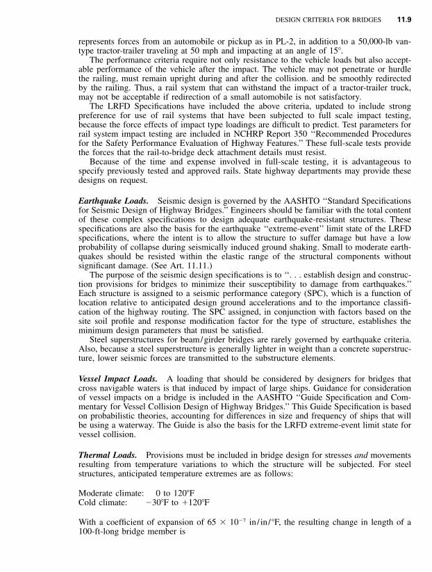
Thermal Loads. Provisions must be included in bridge design for stresses and movementsresulting from temperature variations to which the structure will be subjected. For steelstructures, anticipated temperature extremes are as follows:
Moderate climate: 0 to 120�FCold climate: �30�F to �120�F
With a coefficient of expansion of 65 � 10�7 in / in / �F, the resulting change in length of a100-ft-long bridge member is
If a bridge is erected at the average of high and low temperatures, the resulting change inlength will be one-half of the above.
For complex structures such as trusses and arches, length changes of individual membersmay induce secondary stresses that must be taken into account.
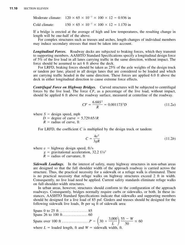
Longitudinal Forces. Roadway decks are subjected to braking forces, which they transmitto supporting members. AASHTO Standard Specifications specify a longitudinal design forceof 5% of the live load in all lanes carrying traffic in the same direction, without impact. Theforce should be assumed to act 6 ft above the deck.
For LRFD, braking forces should be taken as 25% of the axle weights of the design truckor tandem per lane, placed in all design lanes that are considered to be loaded and whichare carrying traffic headed in the same direction. These forces are applied 6.0 ft above thedeck in either longitudinal direction to cause extreme force effects.
Centrifugal Force on Highway Bridges. Curved structures will be subjected to centrifugalforces by the live load. The force CF, as a percentage of the live load, without impact,should be applied 6 ft above the roadway surface, measured at centerline of the roadway.
26.68S 2CF � � 0.00117S D (11.2a)R
where S � design speed, mphD � degree of curve � 5,729.65/RR � radius of curve, ft
For LRFD, the coefficient C is multiplied by the design truck or tandem:
24vC � (11.2b)
3gR
where v � highway design speed, ft / sg � gravitational acceleration, 32.2 f /s2
R � radius of curvature, ft
Sidewalk Loadings. In the interest of safety, many highway structures in non-urban areasare designed so that the full shoulder width of the approach roadway is carried across thestructure. Thus, the practical necessity for a sidewalk or a refuge walk is eliminated. Thereis no practical necessity that refuge walks on highway structures exceed 2 ft in width.Consequently, no live load need be applied. Current safety standards eliminate refuge walkson full-shoulder-width structures.
In urban areas, however, structures should conform to the configuration of the approachroadways. Consequently, bridges normally require curbs or sidewalks, or both. In these in-stances, AASHTO Standard Specifications indicate that sidewalks and supporting membersshould be designed for a live load of 85 psf. Girders and trusses should be designed for thefollowing sidewalk live loads, lb per sq ft of sidewalk area:
* ‘‘Standard Specifications for Highway Bridges,’’ American Association of State Highway and Trans-portation Officials.
For LRFD a load of 75 psf is applied to all sidewalks wider than 2 ft.Structures designed for exclusive use of pedestrians should be designed for 85 psf under
either AASHTO specification.
Curb Loading. For ASD or LFD, curbs should be designed to resist a lateral force of atleast 0.50 kip per lin ft of curb. This force should be applied at the top of the curb or 10 inabove the bridge deck if the curb is higher than 10 in. For LRFD, curbs are limited to nomore than 8 in high.
Where sidewalk, curb, and traffic rail form an integral system, the traffic railing loadingapplies. Stresses in curbs should be computed accordingly.
Wind Loading on Highway Bridges. The wind forces prescribed below, based on theAASHTO Standard Specifications, Group II and Group V loadings, are considered a uni-formly distributed, moving live load. They act on the exposed vertical surfaces of all mem-bers, including the floor system and railing as seen in elevation, at an angle of 90� with thelongitudinal axis of the structure. These forces are presumed for a wind velocity of 100 mph.They may be modified in proportion to the square of the wind velocity if conditions warrantchange.
Superstructure. For trusses and arches: 75 psf but not less than 0.30 kip per lin ft in theplane of loaded chord, nor 0.15 kip per lin ft in the plane of unloaded chord.
For girders and beams: 50 psf but not less than 0.30 kip per lin ft on girder spans.Wind on Live Load. A force of 0.10 kip per lin ft should be applied to the live load,
acting 6 ft above the roadway deck.Substructure. To allow for the effect of varying angles of wind in design of the sub-
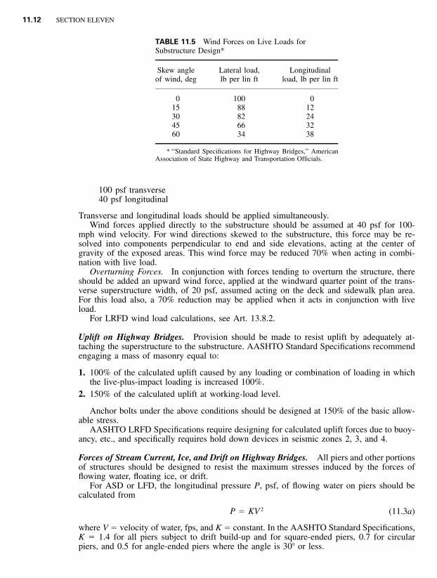
structure, the following longitudinal and lateral wind loads for the skew angles indicatedshould be assumed acting on the superstructure at the center of gravity of the exposed area.
When acting in combination with live load, the wind forces given in Table 11.4 may bereduced 70%. But they should be combined with the wind load on the live load, as givenin Table 11.5.
For usual girder and slab bridges with spans not exceeding about 125 ft, the followingwind loads on the superstructure may be used for substructure design in lieu of the moreelaborate loading specified in Tables 11.4 and 11.5:
Wind on structure50 psf transverse12 psf longitudinal
Wind on live load
11.12 SECTION ELEVEN
TABLE 11.5 Wind Forces on Live Loads forSubstructure Design*
Skew angleof wind, deg
Lateral load,lb per lin ft
Longitudinalload, lb per lin ft
0 100 015 88 1230 82 2445 66 3260 34 38
* ‘‘Standard Specifications for Highway Bridges,’’ AmericanAssociation of State Highway and Transportation Officials.
100 psf transverse40 psf longitudinal
Transverse and longitudinal loads should be applied simultaneously.Wind forces applied directly to the substructure should be assumed at 40 psf for 100-
mph wind velocity. For wind directions skewed to the substructure, this force may be re-solved into components perpendicular to end and side elevations, acting at the center ofgravity of the exposed areas. This wind force may be reduced 70% when acting in combi-nation with live load.
Overturning Forces. In conjunction with forces tending to overturn the structure, thereshould be added an upward wind force, applied at the windward quarter point of the trans-verse superstructure width, of 20 psf, assumed acting on the deck and sidewalk plan area.For this load also, a 70% reduction may be applied when it acts in conjunction with liveload.
For LRFD wind load calculations, see Art. 13.8.2.
Uplift on Highway Bridges. Provision should be made to resist uplift by adequately at-taching the superstructure to the substructure. AASHTO Standard Specifications recommendengaging a mass of masonry equal to:
1. 100% of the calculated uplift caused by any loading or combination of loading in whichthe live-plus-impact loading is increased 100%.
2. 150% of the calculated uplift at working-load level.
Anchor bolts under the above conditions should be designed at 150% of the basic allow-able stress.
AASHTO LRFD Specifications require designing for calculated uplift forces due to buoy-ancy, etc., and specifically requires hold down devices in seismic zones 2, 3, and 4.
Forces of Stream Current, Ice, and Drift on Highway Bridges. All piers and other portionsof structures should be designed to resist the maximum stresses induced by the forces offlowing water, floating ice, or drift.
For ASD or LFD, the longitudinal pressure P, psf, of flowing water on piers should becalculated from
2P � KV (11.3a)
where V � velocity of water, fps, and K � constant. In the AASHTO Standard Specifications,K � 1.4 for all piers subject to drift build-up and for square-ended piers, 0.7 for circularpiers, and 0.5 for angle-ended piers where the angle is 30� or less.
DESIGN CRITERIA FOR BRIDGES 11.13
In the ASSHTO LRFD Specifications, the pressure P, ksf, is calculated from
2C VDP � (11.3b)1000
where V � velocity of water, fps, for design flood and appropriate limit state, and CD is adrag coefficient (0.7 for semi-circular nosed pier, 1.4 for square ended pier, 1.4 for debrislaunched against pier, and 0.8 for wedge nosed pier with nose angle 90� or less).
For ice and drift loads, see AASHTO specifications.Buoyancy should be taken into account in the design of substructures, including piling,
and of superstructures, where necessary.
11.5 LOAD COMBINATIONS AND EFFECTS
11.5.1 Overview
The following groups represent various combinations of service loads and forces to whicha structure may be subjected. Every component of substructure and superstructure should beproportioned to resist all combinations of forces applicable to the type of bridge and its site.
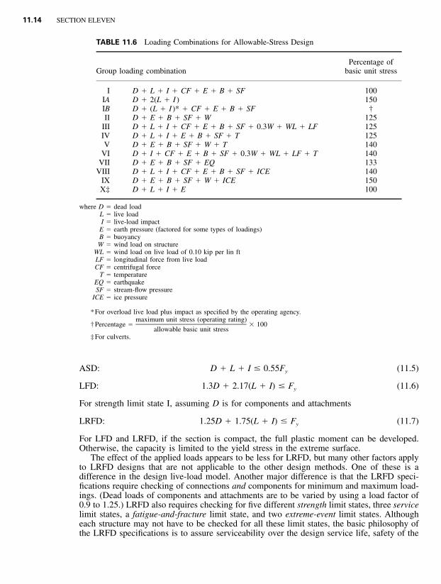
For working-stress design, allowable unit stresses depend on the loading group, as indi-cated in Table 11.6. These stresses, however, do not govern for members subject to repeatedstresses when allowable fatigue stresses are smaller. Note that no increase is permitted inallowable stresses for members carrying only wind loads. When the section required for eachloading combination has been determined, the largest should be selected for the memberbeing designed.
The ‘‘Standard Specifications for Highway Bridges’’ of the American Association of StateHighway and Transportation Officials specifies for LFD, factors to be applied to the varioustypes of loads in loading combinations. These load factors are based on statistical analysisof loading histories. In addition, in LRFD, reduction factors are applied to the nominalresistance of materials in members and to compensate for various uncertainties in behavior.
To compare the effects of the design philosophies of ASD, LFD, and LRFD, the grouploading requirements of the three methods will be examined. For simplification, only D, L,and I of Group I loading will be considered. Although not stated, all three methods can beconsidered to use the same general equation for determining the effects of the combinationof loads:
N�(F � load) � RF � nominal resistance (11.4)
where N � design factor used in LRFD for ductility, redundancy, and operationalimportance of the bridge
� 1.0 for ASD and LFD�(F � load) � sum of the factored loads for a combination of loads
F � load factor that is applied to a specific load� 1.0 for ASD; D, L, and I
load � one or more service loads that must be considered in the designRF � resistance factor (safety factor for ASD) that is applied to the nominal
resistanceNominal resistance � the strength of a member based on the type of loading; e.g., tension,
compression, or shear
For a non-compact flexural member subjected to bending by dead load, live load, andimpact forces, let D, L, I represent the maximum tensile stress in the extreme surface dueto dead load, live load, and impact, respectively. Then, for each of the design methods, thefollowing must be satisfied:
11.14 SECTION ELEVEN
TABLE 11.6 Loading Combinations for Allowable-Stress Design
Group loading combinationPercentage of
basic unit stress
I D � L � I � CF � E � B � SF 100IA D � 2(L � I ) 150IB D � (L � I )* � CF � E � B � SF †II D � E � B � SF � W 125
III D � L � I � CF � E � B � SF � 0.3W � WL � LF 125IV D � L � I � E � B � SF � T 125V D � E � B � SF � W � T 140
VI D � I � CF � E � B � SF � 0.3W � WL � LF � T 140VII D � E � B � SF � EQ 133
VIII D � L � I � CF � E � B � SF � ICE 140IX D � E � B � SF � W � ICE 150X‡ D � L � I � E 100
where D � dead loadL � live loadI � live-load impact
E � earth pressure (factored for some types of loadings)B � buoyancyW � wind load on structure
WL � wind load on live load of 0.10 kip per lin ftLF � longitudinal force from live loadCF � centrifugal force
T � temperatureEQ � earthquakeSF � stream-flow pressure
ICE � ice pressure
* For overload live load plus impact as specified by the operating agency.
† Percentage � � 100maximum unit stress (operating rating)
allowable basic unit stress‡ For culverts.
ASD: D � L � I � 0.55F (11.5)y
LFD: 1.3D � 2.17(L � I) � F (11.6)y
For strength limit state I, assuming D is for components and attachments
LRFD: 1.25D � 1.75(L � I) � F (11.7)y
For LFD and LRFD, if the section is compact, the full plastic moment can be developed.Otherwise, the capacity is limited to the yield stress in the extreme surface.
The effect of the applied loads appears to be less for LRFD, but many other factors applyto LRFD designs that are not applicable to the other design methods. One of these is adifference in the design live-load model. Another major difference is that the LRFD speci-fications require checking of connections and components for minimum and maximum load-ings. (Dead loads of components and attachments are to be varied by using a load factor of0.9 to 1.25.) LRFD also requires checking for five different strength limit states, three servicelimit states, a fatigue-and-fracture limit state, and two extreme-event limit states. Althougheach structure may not have to be checked for all these limit states, the basic philosophy ofthe LRFD specifications is to assure serviceability over the design service life, safety of the
DESIGN CRITERIA FOR BRIDGES 11.15
bridge through redundancy and ductility of all components and connections, and survival(prevention of collapse) of the bridge when subjected to an extreme event; e.g., a 500-yearflood. (See Art. 11.5.4.)
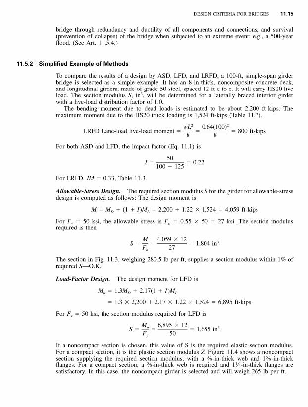
11.5.2 Simplified Example of Methods
To compare the results of a design by ASD. LFD, and LRFD, a 100-ft, simple-span girderbridge is selected as a simple example. It has an 8-in-thick, noncomposite concrete deck,and longitudinal girders, made of grade 50 steel, spaced 12 ft c to c. It will carry HS20 liveload. The section modulus S, in3, will be determined for a laterally braced interior girderwith a live-load distribution factor of 1.0.
The bending moment due to dead loads is estimated to be about 2,200 ft-kips. Themaximum moment due to the HS20 truck loading is 1,524 ft-kips (Table 11.7).
For Fy � 50 ksi, the section modulus required for LFD is
M 6,895 � 12u 3S � � � 1,655 inF 50y
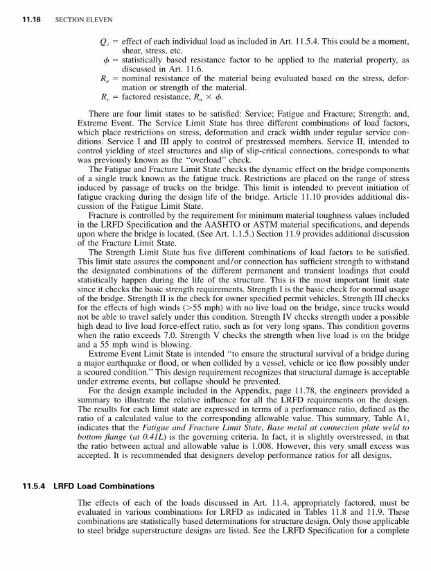
If a noncompact section is chosen, this value of S is the required elastic section modulus.For a compact section, it is the plastic section modulus Z. Figure 11.4 shows a noncompactsection supplying the required section modulus, with a 3⁄8-in-thick web and 15⁄8-in-thickflanges. For a compact section, a 5⁄8-in-thick web is required and 11⁄4-in-thick flanges aresatisfactory. In this case, the noncompact girder is selected and will weigh 265 lb per ft.
11.16 SECTION ELEVEN
TABLE 11.7 Maximum Moments, Shears, and Reactions for Truck or Lane Loads on One Lane, Simple Spans*
* Based on ‘‘Standard Specifications for Highway Bridges,’’ American Association of State Highway and Transportation Officials. Impactnot included.
† Moments in thousands of ft-lb (ft-kips).‡ Shear and reaction in kips. Concentrated load is considered placed at the support. Loads used are those stipulated for shear.§ Maximum value determined by standard truck loading. Otherwise, standard lane loading governs.
Load-and-Resistance-Factor Design. The live-load moment ML is produced by a combi-nation of truck and lane loads, with impact applied only to the truck moment:
M � 1.33 � 1524 � 800 � 2827 ft-kipsL
The load factor N is a combination of factors applied to the loadings. Assume that the bridgehas ductility (0.95), redundancy (0.95), and is of operational importance (1.05). Thus, N �0.95 � 0.95 � 1.05 � 0.95. The design moment for limit state I is
M � N[F M � F M ]u D D L L
� 0.95[1.25 � 2200 � 1.75 � 2827] � 7312 ft-kips
Hence, since the resistance factor for flexure is 1.0, the section modulus required for LRFDis
DESIGN CRITERIA FOR BRIDGES 11.17
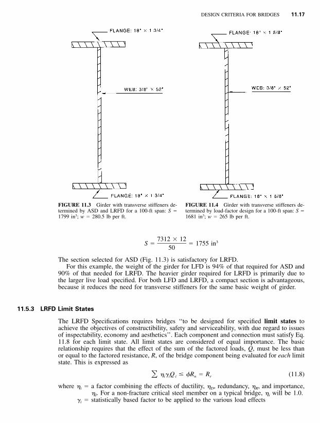
FIGURE 11.3 Girder with transverse stiffeners de-termined by ASD and LRFD for a 100-ft span: S �1799 in3; w � 280.5 lb per ft.
FIGURE 11.4 Girder with transverse stiffeners de-termined by load-factor design for a 100-ft span: S �1681 in3; w � 265 lb per ft.
7312 � 12 3S � � 1755 in50
The section selected for ASD (Fig. 11.3) is satisfactory for LRFD.For this example, the weight of the girder for LFD is 94% of that required for ASD and
90% of that needed for LRFD. The heavier girder required for LRFD is primarily due tothe larger live load specified. For both LFD and LRFD, a compact section is advantageous,because it reduces the need for transverse stiffeners for the same basic weight of girder.
11.5.3 LRFD Limit States
The LRFD Specifications requires bridges ‘‘to be designed for specified limit states toachieve the objectives of constructibility, safety and serviceability, with due regard to issuesof inspectability, economy and aesthetics’’. Each component and connection must satisfy Eq.11.8 for each limit state. All limit states are considered of equal importance. The basicrelationship requires that the effect of the sum of the factored loads, Q, must be less thanor equal to the factored resistance, R, of the bridge component being evaluated for each limitstate. This is expressed as
� � Q � �R � R (11.8)� i i i n r
where �i � a factor combining the effects of ductility, �D, redundancy, �R, and importance,�I. For a non-fracture critical steel member on a typical bridge, �i will be 1.0.
�i � statistically based factor to be applied to the various load effects
11.18 SECTION ELEVEN
Qi � effect of each individual load as included in Art. 11.5.4. This could be a moment,shear, stress, etc.
� � statistically based resistance factor to be applied to the material property, asdiscussed in Art. 11.6.
Rn � nominal resistance of the material being evaluated based on the stress, defor-mation or strength of the material.
Rr � factored resistance, Rn � �.
There are four limit states to be satisfied: Service; Fatigue and Fracture; Strength; and,Extreme Event. The Service Limit State has three different combinations of load factors,which place restrictions on stress, deformation and crack width under regular service con-ditions. Service I and III apply to control of prestressed members. Service II, intended tocontrol yielding of steel structures and slip of slip-critical connections, corresponds to whatwas previously known as the ‘‘overload’’ check.
The Fatigue and Fracture Limit State checks the dynamic effect on the bridge componentsof a single truck known as the fatigue truck. Restrictions are placed on the range of stressinduced by passage of trucks on the bridge. This limit is intended to prevent initiation offatigue cracking during the design life of the bridge. Article 11.10 provides additional dis-cussion of the Fatigue Limit State.
Fracture is controlled by the requirement for minimum material toughness values includedin the LRFD Specification and the AASHTO or ASTM material specifications, and dependsupon where the bridge is located. (See Art. 1.1.5.) Section 11.9 provides additional discussionof the Fracture Limit State.
The Strength Limit State has five different combinations of load factors to be satisfied.This limit state assures the component and/or connection has sufficient strength to withstandthe designated combinations of the different permanent and transient loadings that couldstatistically happen during the life of the structure. This is the most important limit statesince it checks the basic strength requirements. Strength I is the basic check for normal usageof the bridge. Strength II is the check for owner specified permit vehicles. Strength III checksfor the effects of high winds (�55 mph) with no live load on the bridge, since trucks wouldnot be able to travel safely under this condition. Strength IV checks strength under a possiblehigh dead to live load force-effect ratio, such as for very long spans. This condition governswhen the ratio exceeds 7.0. Strength V checks the strength when live load is on the bridgeand a 55 mph wind is blowing.
Extreme Event Limit State is intended ‘‘to ensure the structural survival of a bridge duringa major earthquake or flood, or when collided by a vessel, vehicle or ice flow possibly undera scoured condition.’’ This design requirement recognizes that structural damage is acceptableunder extreme events, but collapse should be prevented.
For the design example included in the Appendix, page 11.78, the engineers provided asummary to illustrate the relative influence for all the LRFD requirements on the design.The results for each limit state are expressed in terms of a performance ratio, defined as theratio of a calculated value to the corresponding allowable value. This summary, Table A1,indicates that the Fatigue and Fracture Limit State, Base metal at connection plate weld tobottom flange (at 0.41L) is the governing criteria. In fact, it is slightly overstressed, in thatthe ratio between actual and allowable value is 1.008. However, this very small excess wasaccepted. It is recommended that designers develop performance ratios for all designs.
11.5.4 LRFD Load Combinations
The effects of each of the loads discussed in Art. 11.4, appropriately factored, must beevaluated in various combinations for LRFD as indicated in Tables 11.8 and 11.9. Thesecombinations are statistically based determinations for structure design. Only those applicableto steel bridge superstructure designs are listed. See the LRFD Specification for a complete
DESIGN CRITERIA FOR BRIDGES 11.19
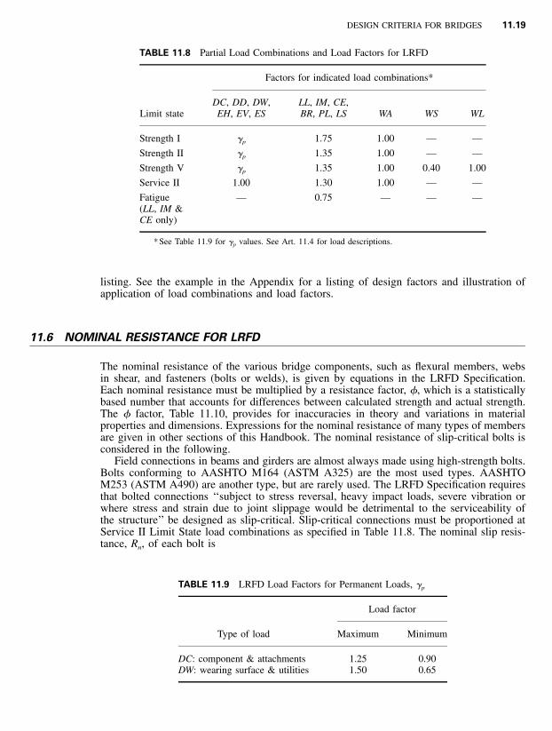
TABLE 11.8 Partial Load Combinations and Load Factors for LRFD
Limit state
Factors for indicated load combinations*
DC, DD, DW,EH, EV, ES
LL, IM, CE,BR, PL, LS WA WS WL
Strength I �p 1.75 1.00 — —
Strength II �p 1.35 1.00 — —
Strength V �p 1.35 1.00 0.40 1.00
Service II 1.00 1.30 1.00 — —
Fatigue(LL, IM &CE only)
— 0.75 — — —
* See Table 11.9 for �p values. See Art. 11.4 for load descriptions.
TABLE 11.9 LRFD Load Factors for Permanent Loads, �p
listing. See the example in the Appendix for a listing of design factors and illustration ofapplication of load combinations and load factors.
11.6 NOMINAL RESISTANCE FOR LRFD
The nominal resistance of the various bridge components, such as flexural members, websin shear, and fasteners (bolts or welds), is given by equations in the LRFD Specification.Each nominal resistance must be multiplied by a resistance factor, �, which is a statisticallybased number that accounts for differences between calculated strength and actual strength.The � factor, Table 11.10, provides for inaccuracies in theory and variations in materialproperties and dimensions. Expressions for the nominal resistance of many types of membersare given in other sections of this Handbook. The nominal resistance of slip-critical bolts isconsidered in the following.
Field connections in beams and girders are almost always made using high-strength bolts.Bolts conforming to AASHTO M164 (ASTM A325) are the most used types. AASHTOM253 (ASTM A490) are another type, but are rarely used. The LRFD Specification requiresthat bolted connections ‘‘subject to stress reversal, heavy impact loads, severe vibration orwhere stress and strain due to joint slippage would be detrimental to the serviceability ofthe structure’’ be designed as slip-critical. Slip-critical connections must be proportioned atService II Limit State load combinations as specified in Table 11.8. The nominal slip resis-tance, Rn, of each bolt is
11.20 SECTION ELEVEN
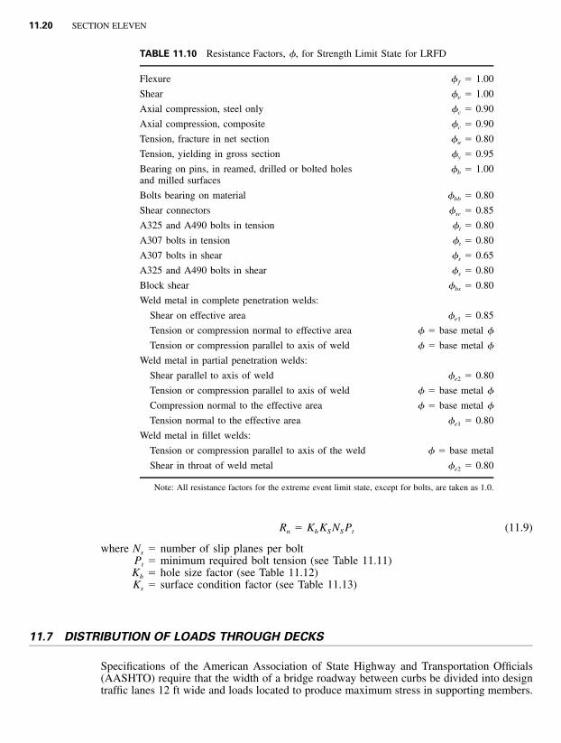
TABLE 11.10 Resistance Factors, �, for Strength Limit State for LRFD
Flexure �ƒ � 1.00
Shear �v � 1.00
Axial compression, steel only �c � 0.90
Axial compression, composite �c � 0.90
Tension, fracture in net section �u � 0.80
Tension, yielding in gross section �y � 0.95
Bearing on pins, in reamed, drilled or bolted holesand milled surfaces
�b � 1.00
Bolts bearing on material �bb � 0.80
Shear connectors �sc � 0.85
A325 and A490 bolts in tension �t � 0.80
A307 bolts in tension �t � 0.80
A307 bolts in shear �s � 0.65
A325 and A490 bolts in shear �s � 0.80
Block shear �bs � 0.80
Weld metal in complete penetration welds:
Shear on effective area �e1 � 0.85
Tension or compression normal to effective area � � base metal �
Tension or compression parallel to axis of weld � � base metal �
Weld metal in partial penetration welds:
Shear parallel to axis of weld �e2 � 0.80
Tension or compression parallel to axis of weld � � base metal �
Compression normal to the effective area � � base metal �
Tension normal to the effective area �e1 � 0.80
Weld metal in fillet welds:
Tension or compression parallel to axis of the weld � � base metal
Shear in throat of weld metal �e2 � 0.80
Note: All resistance factors for the extreme event limit state, except for bolts, are taken as 1.0.
R � K K N P (11.9)n h S S t
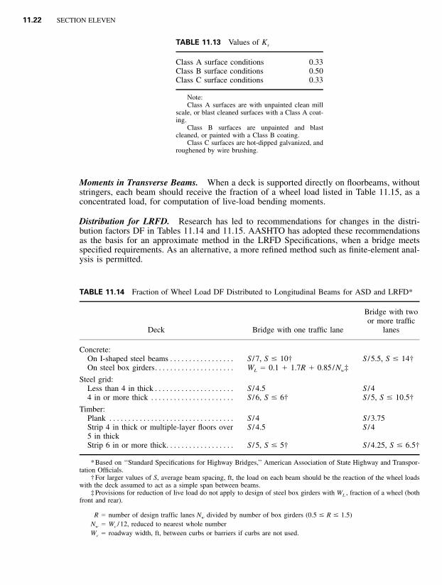
where Ns � number of slip planes per boltPt � minimum required bolt tension (see Table 11.11)Kh � hole size factor (see Table 11.12)Ks � surface condition factor (see Table 11.13)
11.7 DISTRIBUTION OF LOADS THROUGH DECKS
Specifications of the American Association of State Highway and Transportation Officials(AASHTO) require that the width of a bridge roadway between curbs be divided into designtraffic lanes 12 ft wide and loads located to produce maximum stress in supporting members.
Oversize and short-slotted holes 0.85Long-slotted holes with slot perpendicular to direction of force 0.70Long-slotted holes with slot parallel to direction of force 0.60
(Fractional parts of design lanes are not used.) Roadway widths from 20 to 24 ft, however,should have two design lanes, each equal to one-half the roadway width. Truck and laneloadings are assumed to occupy a width of 10 ft placed anywhere within the design lane toproduce maximum effect.
If curbs, railings, and wearing surfaces are placed after the concrete deck has gainedsufficient strength, their weight may be distributed equally to all stringers or beams. Other-wise, the dead load on the outside stringer or beam is the portion of the slab it carries.
The strength and stiffness of the deck determine, to some extent, the distribution of thelive load to the supporting framing.
Shear. For determining end shears and reactions, the deck may be assumed to act as asimple span between beams for lateral distribution of the wheel load. For shear elsewhere,the wheel load should be distributed by the method required for bending moment.
Moments in Longitudinal Beams. For ASD and LRFD, the fraction of a wheel load listedin Table 11.14 should be applied to each interior longitudinal beam for computation of live-load bending moments.
For an outer longitudinal beam, the live-load bending moments should be determinedwith the reaction of the wheel load when the deck is assumed to act as a simple span betweenbeams. When four or more longitudinal beams carry a concrete deck, the fraction of a wheelload carried by an outer beam should be at least S /5.5 when the distance between that beamand the adjacent interior beam S, ft, is 6 or less. For 6 � S � 14, the fraction should be atleast S / (4 � 0.25S). For S � 14, no minimum need be observed.
11.22 SECTION ELEVEN
TABLE 11.13 Values of Ks
Class A surface conditions 0.33Class B surface conditions 0.50Class C surface conditions 0.33
Note:Class A surfaces are with unpainted clean mill
scale, or blast cleaned surfaces with a Class A coat-ing.
Class B surfaces are unpainted and blastcleaned, or painted with a Class B coating.
Class C surfaces are hot-dipped galvanized, androughened by wire brushing.
TABLE 11.14 Fraction of Wheel Load DF Distributed to Longitudinal Beams for ASD and LRFD*
Steel grid:Less than 4 in thick . . . . . . . . . . . . . . . . . . . . . S / 4.5 S / 44 in or more thick . . . . . . . . . . . . . . . . . . . . . . S / 6, S � 6† S / 5, S � 10.5†
Timber:Plank . . . . . . . . . . . . . . . . . . . . . . . . . . . . . . . . . S / 4 S / 3.75Strip 4 in thick or multiple-layer floors over5 in thick
S / 4.5 S / 4
Strip 6 in or more thick. . . . . . . . . . . . . . . . . . S / 5, S � 5† S / 4.25, S � 6.5†
* Based on ‘‘Standard Specifications for Highway Bridges,’’ American Association of State Highway and Transpor-tation Officials.
† For larger values of S, average beam spacing, ft, the load on each beam should be the reaction of the wheel loadswith the deck assumed to act as a simple span between beams.
‡ Provisions for reduction of live load do not apply to design of steel box girders with WL , fraction of a wheel (bothfront and rear).
R � number of design traffic lanes N divided by number of box girders (0.5 � R � 1.5)w
N � W / 12, reduced to nearest whole numberw c
W � roadway width, ft, between curbs or barriers if curbs are not used.c
Moments in Transverse Beams. When a deck is supported directly on floorbeams, withoutstringers, each beam should receive the fraction of a wheel load listed in Table 11.15, as aconcentrated load, for computation of live-load bending moments.
Distribution for LRFD. Research has led to recommendations for changes in the distri-bution factors DF in Tables 11.14 and 11.15. AASHTO has adopted these recommendationsas the basis for an approximate method in the LRFD Specifications, when a bridge meetsspecified requirements. As an alternative, a more refined method such as finite-element anal-ysis is permitted.
DESIGN CRITERIA FOR BRIDGES 11.23
TABLE 11.15 Fraction of Wheel Load Distributed to Transverse Beams*
* Based on ‘‘Standard Specifications for Highway Bridges,’’ American Association of State Highway and Transpor-tation Officials.
† When the spacing of beams S, ft, exceeds the denominator, the load on the beam should be the reaction of thewheel loads when the deck is assumed to act as a simple span between beams.
The LRFD Specification gives the following equations as the approximate method fordetermining the distribution factor for moment for steel girders. They are in terms of theLRFD design truck load per lane, and their application is illustrated in the design examplein the Appendix. For one lane loaded
0.4 0.3 0.1KS S gDF � 0.06 � (11.10)� � � � � �314 L 12Lt s
For two lanes loaded
0.6 0.2 3 0.1DF � 0.075 � (S /9.5) (S /L) (K /12Lt ) (11.11)g s
where S � beam spacing, ftL � span, ftts � thickness of concrete slab, in
Kg � n(I � Aeg2)
n � modular ratio � ratio of steel modulus of elasticity Es to the modulus of elasticityEc of the concrete slab
I � moment of inertia, in4, of the beamA � area, in2, of the beameg � distance, in, from neutral axis of beam to center of gravity of concrete slab
Eq. 11.10 and 11.11 apply only for spans from 20 ft to 240 ft with 4-1⁄2 to 12 in thickconcrete decks (or concrete filled, or partially filled, steel grid decks), on four or more steelgirders spaced between 3.5 ft and 16.0 ft. The multiple presence factors, m, in Table 11.2are not to be used when this approximate method of load distribution is used. For girderspacing outside the above limits, the live load on each beam is determined by the lever rule(summing moments about one support to find the reaction at another support by assumingthe supported component is hinged at interior supports). When more refined methods ofanalysis are used, the LRFD Specification states that ‘‘a table of live load distribution co-efficients for extreme force effects in each span shall be provided in the contract documentsto aid in permit issuance and rating of the bridge.’’
11.24 SECTION ELEVEN
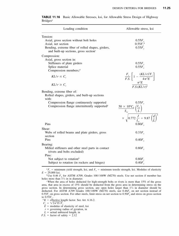
11.8 BASIC ALLOWABLE STRESSES FOR BRIDGES
Table 11.16 lists the basic allowable stresses for highway bridges recommended in AASHTO‘‘Standard Specifications for Highway Bridges’’ for ASD. The stresses are related to theminimum yield strength Fy , ksi, or minimum tensile strength Fu, ksi, of the material in allcases except those for which stresses are independent of the grade of steel being used.
The basic stresses may be increased for loading combinations (Art. 11.5). They may besuperseded by allowable fatigue stresses (Art. 11.10).
Allowable Stresses in Welds. Standard specifications require that weld metal used inbridges conform to the ‘‘Bridge Welding Code,’’ ANSI/AASHTO/AWS D1.5, AmericanWelding Society.
Yield and tensile strengths of weld metal usually are specified to be equal to or greaterthan the corresponding strengths of the base metal. The allowable stresses for welds inbridges generally are as follows:
Groove welds are permitted the same stress as the base metal joined. When base metalsof different yield strengths are groove-welded, the lower yield strength governs.
Fillet welds are allowed a shear stress of 0.27Fu, where Fu is the tensile strength of theelectrode classification or the tensile strength of the connected part, whichever is less. Whenquenched and tempered steels are joined, an electrode classification with strength less thanthat of the base metal may be used for fillet welds, but this should be clearly specified inthe design drawings.
Plug welds are permitted a shear stress of 12.4 ksi.These stresses may be superseded by fatigue requirements (Art. 11.10). The basic stresses
may be increased for loading combinations as noted in Art. 11.5.Effective area of groove and fillet welds for computation of stresses equals the effective
length times effective throat thickness. The effective shearing area of plug welds equals thenominal cross-sectional area of the hole in the plane of the faying surface.
Effective length of a groove weld is the width of the parts joined, perpendicular to thedirection of stress. The effective length of a straight fillet weld is the overall length of thefull-sized fillet, including end returns. For a curved fillet weld, the effective length is thelength of line generated by the center point of the effective throat thickness. For a fillet weldin a hole or slot, if the weld area computed from this length is greater than the area of thehole in the plane of the faying surface, the latter area should be used as the effective area.
Effective throat thickness of a groove weld is the thickness of the thinner piece of basemetal joined. (No increase is permitted for weld reinforcement. It should be removed bygrinding to improve fatigue strength.) The effective throat thickness of a fillet weld is theshortest distance from the root to the face, computed as the length of the altitude on thehypotenuse of a right triangle. For a combination partial-penetration groove weld and a filletweld, the effective throat is the shortest distance from the root to the face minus 1⁄8 in forany groove with an included angle less than 60� at the root of the groove.
In some cases, strength may not govern the design. Standard specifications set maximumand minimum limits on size and spacing of welds. These are discussed in Art. 5.19.
Rollers and Expansion Rockers. The maximum compressive load, Pm, kips, should notexceed the following:
for cylindrical surfaces,
2FWD y1P � 8 (11.12)� �m 1 � D /D E1 2 s
for spherical surfaces,
DESIGN CRITERIA FOR BRIDGES 11.25
TABLE 11.16 Basic Allowable Stresses, ksi, for Allowable Stress Design of HighwayBridgesa
Loading condition Allowable stress, ksi
Tension:Axial, gross section without bolt holes 0.55Fy
Shear:Webs of rolled beams and plate girders, grosssection
0.33Fy
Pins 0.40Fy
Bearing:Milled stiffeners and other steel parts in contact
(rivets and bolts excluded)0.80Fy
Pins:Not subject to rotationh 0.80Fy
Subject to rotation (in rockers and hinges) 0.40Fy
a Fy � minimum yield strength, ksi, and Fu � minimum tensile strength, ksi. Modulus of elasticityE � 29,000 ksi.
b Use 0.46 Fu for ASTM A709, Grades 100 / 100W (M270) steels. Use net section if member hasholes more than 11⁄4 in in diameter.
c When the area of holes deducted for high-strength bolts or rivets is more than 15% of the grossarea, that area in excess of 15% should be deducted from the gross area in determining stress on thegross section. In determining gross section, any open holes larger than 11⁄4 in diameter should bededucted. For ASTM A709 Grades 100 / 100W (M270) steels, use 0.46Fu on net section instead of0.55Fy on gross section. For other steels, limit stress on net section to 0.50Fu and stress on gross sectionto 0.55Fy .
d K � effective length factor. See Art. 6.16.2.Cc � 2�2� E / Fy
E � modulus of elasticity of steel, ksir � governing radius of gyration, inL � actual unbraced length, in
F.S. � factor of safety � 2.12
11.26 SECTION ELEVEN
TABLE 11.16 Basic Allowable Stresses, ksi, for Allowable Stress Design of HighwayBridgesa (Continued )
g Not to exceed 0.55Fy .L � length, in, of unsupported flange between lateral connections, knee braces, or other points of support
Iyc � moment of inertia of compression flange about the vertical axis in the plane of the web, in4
d � depth of girder, in
J �where b and t are the flange width and thickness, in, of the compression and
3 3 3[(bt ) � (bt ) � Dtc t w ,3
tension flange, respectively, and tw and D are the web thickness and depth, in, respectivelySxc � section modulus with respect to compression flange, in3
Cb � 1.75 � 1.05 (M1 / M2) � 0.3 (M1 / M2)2 � 2.3 where M1 is the smaller and M2 the larger end moment inthe unbraced segment of the beam; M1 / M2 is positive when the moments cause reverse curvature andnegative when bent in single curvature.
Cb � 1.0 for unbraced cantilevers and for members where the moment within a significant portion of theunbraced segment is greater than or equal to the larger of the segment end moments.
For the use of larger Cb values, see Structural Stability Research Council Guide to Stability DesignCriteria for Metal Structures. If cover plates are used, the allowable static stress at the point of theoreticalcutoff should be determined by the formula.
h Applicable to pins used primarily in axially loaded members, such as truss members and cable adjustinglinks, and not applicable to pins used in members subject to rotation by expansion or deflection.
2 3FD y1P � 40 (11.13)� �m 21 � D /D E1 2 s
where D1 � diameter of rocker or roller surface, inD2 � diameter of mating surface, in. D2 should be taken as positive if the curvatures
have the same sign, infinite if the mating surface is flat.Fy � specified minimum yield strength of the least strong steel at the contact surface,
ksiEs � modulus of elasticity of steel, ksiW � width of the bearing, in
Allowable Stresses for Bolts. Bolted shear connections are classified as either bearing-typeor slip-critical. The latter are required for connections subject to stress reversal, heavy impact,large vibrations, or where joint slippage would be detrimental to the serviceability of thebridge. These connections are discussed in Sec. 5. Bolted bearing-type connections are re-stricted to members in compression and secondary members.
Fasteners for bearing-type connections may be ASTM A307 carbon-steel bolts or A325or A490 high-strength bolts. High-strength bolts are required for slip-critical connections andwhere fasteners are subjected to tension or combined tension and shear.
Bolts for highway bridges are generally 3⁄4 or 7⁄8 in in diameter. Holes for high-strengthbolts may be standard, oversize, short-slotted, or long-slotted. Standard holes may be up to1⁄16 in larger in diameter than the nominal diameters of the bolts. Oversize holes may havea maximum diameter of 15⁄16 in for 3⁄4-in bolts and 11⁄16 in for 7⁄8-in bolts. Minimum diameterof a slotted hole is the same as that of a standard hole. For 3⁄4-in and 7⁄8-in bolts, short-slotted holes may be up to 1 in and 11⁄8 in long, respectively, and long-slotted holes, amaximum of 17⁄8 and 23⁄16 in long, respectively.
In the computation of allowable loads for shear or tension on bolts, the cross-sectionalarea should be based on the nominal diameter of the bolts. For bearing, the area should betaken as the product of the nominal diameter of the bolt and the thickness of the metal onwhich it bears.
Allowable stresses for bolts specified in ‘‘Standard Specifications for Highway Bridges’’of the American Association of State Highway and Transportation Officials (AASHTO) aresummarized in Tables 11.17 and 11.18. The percentages of stress increase specified for loadcombinations in Art. 11.5 also apply to high-strength bolts in slip-critical joints, but thepercentage may not exceed 133%.
DESIGN CRITERIA FOR BRIDGES 11.27
TABLE 11.17 Allowable Stresses, ksi, on Bolts in Highway Bridges—ASD
ASTMdesignation
Allowable tension,Ft
Allowable shear, Fv
Slip-critical connections
Standard-sizeholes
Oversize and short-slotted holes
Long-slotted holes
Transverseload
Parallelload
Bearing-typejoints
A307 18 11
A325 38a 1915*23†15‡
13*19†13‡
11*16†11‡
9*14†9‡
A490 47a 2519*29†19‡
16*24†16‡
13*20†13‡
11*17†11‡
* Class A: When contact surfaces have a slip coefficient of 0.33, such as clean mill scale and blast-cleaned surfaces, with Class Acoating.
† Class B: When contact surfaces have a slip coefficient of 0.50, such as blast-cleaned surfaces and such surfaces with Class B coating.‡Class C: When contact surfaces have a slip coefficient of 0.40, such as hot-dipped galvanized and roughened surfaces.Class A and B coatings include those with a mean slip coefficient of as least 0.33 or 0.50, respectively. See Appendix A, ‘‘Specification
for Structural Joints Using ASTM A325 or A490 Bolts,’’ Research Council on Structural Connections of the Engineering Foundation.
Single bolt in line of force in astandard or short-slotted hole
0.9Fu*† 0.9Fu*†
Two or more bolts in line of forcein standard or short-slotted holes
1.1Fu*† 1.1Fu*
Bolts in long-slotted holes 0.9Fu*† 0.9Fu*
* Fu � specified minimum tensile strength of connected parts. Connections with boltsin oversize holes or in slotted holes with the load applied less than about 80� or morethan about 100� to the axis of the slot should be designed for a slip resistance less thanthat computed from Eq. 11.14.
† Not applicable when the distance, parallel to the load, from the center of a bolt tothe edge of the connected part is less than 11⁄2d, where d is the nominal diameter of thebolt, or the distance to an adjacent bolt is less than 3d.
11.28 SECTION ELEVEN
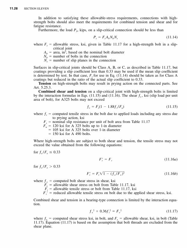
In addition to satisfying these allowable-stress requirements, connections with high-strength bolts should also meet the requirements for combined tension and shear and forfatigue resistance.
Furthermore, the load PS, kips, on a slip-critical connection should be less than
P � F A N N (11.14)s s b b s
where Fs � allowable stress, ksi, given in Table 11.17 for a high-strength bolt in a slip-critical joint
Ab � area, in2, based on the nominal bolt diameterNb � number of bolts in the connectionNs � number of slip planes in the connection
Surfaces in slip-critical joints should be Class A, B, or C, as described in Table 11.17, butcoatings providing a slip coefficient less than 0.33 may be used if the mean slip coefficientis determined by test. In that case, Fs for use in Eq. (11.14) should be taken as for Class Acoatings but reduced in the ratio of the actual slip coefficient to 0.33.
Tension on high-strength bolts may result in prying action on the connected parts. SeeArt. 5.25.3.
Combined shear and tension on a slip-critical joint with high-strength bolts is limitedby the interaction formulas in Eqs. (11.15) and (11.16). The shear ƒv , ksi (slip load per unitarea of bolt), for A325 bolts may not exceed
ƒ � F (1 � 1.88ƒ /F ) (11.15)v s t u
where ƒt � computed tensile stress in the bolt due to applied loads including any stress dueto prying action, ksi
Fs � nominal slip resistance per unit of bolt area from Table 11.17Fu � 120 ksi for A 325 bolts up to 1-in diameter
� 105 ksi for A 325 bolts over 1-in diameter� 150 ksi for A 490 bolts.
Where high-strength bolts are subject to both shear and tension, the tensile stress may notexceed the value obtained from the following equations:
for ƒv /Fv � 0.33
F � � F (11.16a)t t
for ƒv /Fv � 0.33
2F � � F �1 � (ƒ /F ) (11.16b)t t v v
where ƒ v � computed bolt shear stress in shear, ksiFv � allowable shear stress on bolt from Table 11.17, ksiFt � allowable tensile stress or bolt from Table 11.17, ksi
Ft� � reduced allowable tensile stress on bolt due to the applied shear stress, ksi.
Combined shear and tension in a bearing-type connection is limited by the interaction equa-tion.
2 2 2ƒ � 0.36ƒ � F (11.17)v t v
where ƒv � computed shear stress ksi, in bolt, and Fv � allowable shear, ksi, in bolt (Table11.17). Equation (11.17) is based on the assumption that bolt threads are excluded from theshear plane.
DESIGN CRITERIA FOR BRIDGES 11.29
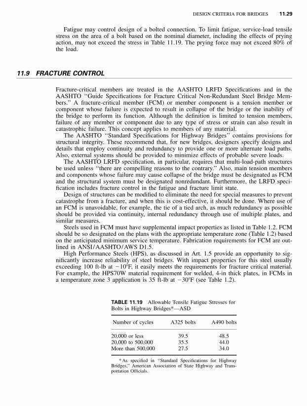
TABLE 11.19 Allowable Tensile Fatigue Stresses forBolts in Highway Bridges*—ASD
Number of cycles A325 bolts A490 bolts
20,000 or less 39.5 48.520,000 to 500,000 35.5 44.0More than 500,000 27.5 34.0
* As specified in ‘‘Standard Specifications for HighwayBridges,’’ American Association of State Highway and Trans-portation Officials.
Fatigue may control design of a bolted connection. To limit fatigue, service-load tensilestress on the area of a bolt based on the nominal diameter, including the effects of pryingaction, may not exceed the stress in Table 11.19. The prying force may not exceed 80% ofthe load.
11.9 FRACTURE CONTROL
Fracture-critical members are treated in the AASHTO LRFD Specifications and in theAASHTO ‘‘Guide Specifications for Fracture Critical Non-Redundant Steel Bridge Mem-bers.’’ A fracture-critical member (FCM) or member component is a tension member orcomponent whose failure is expected to result in collapse of the bridge or the inability ofthe bridge to perform its function. Although the definition is limited to tension members,failure of any member or component due to any type of stress or strain can also result incatastrophic failure. This concept applies to members of any material.
The AASHTO ‘‘Standard Specifications for Highway Bridges’’ contains provisions forstructural integrity. These recommend that, for new bridges, designers specify designs anddetails that employ continuity and redundancy to provide one or more alternate load paths.Also, external systems should be provided to minimize effects of probable severe loads.
The AASHTO LRFD specification, in particular, requires that multi-load-path structuresbe used unless ‘‘there are compelling reasons to the contrary.’’ Also, main tension membersand components whose failure may cause collapse of the bridge must be designated as FCMand the structural system must be designated nonredundant. Furthermore, the LRFD speci-fication includes fracture control in the fatigue and fracture limit state.
Design of structures can be modified to eliminate the need for special measures to preventcatastrophe from a fracture, and when this is cost-effective, it should be done. Where use ofan FCM is unavoidable, for example, the tie of a tied arch, as much redundancy as possibleshould be provided via continuity, internal redundancy through use of multiple plates, andsimilar measures.
Steels used in FCM must have supplemental impact properties as listed in Table 1.2. FCMshould be so designated on the plans with the appropriate temperature zone (Table 1.2) basedon the anticipated minimum service temperature. Fabrication requirements for FCM are out-lined in ANSI/AASHTO/AWS D1.5.
High Performance Steels (HPS), as discussed in Art. 1.5 provide an opportunity to sig-nificantly increase reliability of steel bridges. With impact properties for this steel usuallyexceeding 100 ft-lb at �10�F, it easily meets the requirements for fracture critical material.For example, the HPS70W material requirement for welded, 4-in thick plates, in FCMs ina temperature zone 3 application is 35 ft-lb at �30�F (see Table 1.2).
11.30 SECTION ELEVEN
11.10 REPETITIVE LOADINGS
Most structural damage to steel bridges is the result of repetitive loading from trucks orwind. Often, the damage is caused by secondary effects, for example, when live loads aredistributed transversely through cross frames and induce large out-of-plane distortions thatwere not taken into account in design of the structure. Such strains may initiate small fatiguecracks. Under repetitive loads, the cracks grow. Unless the cracks are discovered early andremedial action taken, they may create instability under a combination of stress, loading rate,and temperature, and brittle fracture could occur. Proper detailing of steel bridges can preventsuch fatigue crack initiation.
To reduce the probability of fracture, the structural steels included in the AASHTO spec-ifications for M270 steels, and ASTM A709 steels when ‘‘supplemental requirements’’ areordered,* are required to have minimum impact properties (Art. 1.1.5). The higher the impactresistance of the steel, the larger a crack has to be before it is susceptible to unstable growth.With the minimum impact properties required for bridge steels, the crack should be largeenough to allow discovery during the biannual bridge inspection before fracture occurs. TheM270 specification requires average energy in a Charpy V-notch test of 15 ft-lb for grade36 steels and ranging up to 35 ft-lb for grade 100 steels, at specified test temperatures. Moreconservative values are specified for FCM members (Art. 11.9). Toughness values dependon the lowest ambient service temperature (LAST) to which the structure may be subjected.Test temperatures are 70�F higher than the LAST to take into account the difference betweenthe loading rate as applied by highway trucks and the Charpy V-notch impact tests.
Allowable Fatigue Stresses for ASD and LFD Design. Members, connections, welds, andfasteners should be designed so that maximum stresses do not exceed the basic allowablestresses (Art. 11.8) and the range in stress due to loads does not exceed the allowable fatiguestress range. Table 11.20A lists allowable fatigue stress ranges in accordance with the numberof cycles to which a member or component will be subjected and several stress categoriesfor structural details. The details described in Table 6.27 for structural steel for buildings aregenerally applicable also to highway bridges. The diagrams are provided as illustrative ex-amples and are not intended to exclude other similar construction. (See also Art. 6.26.) Theallowable stresses apply to load combinations that include live loads and wind. For deadplus wind loads, use the stress range for 100,000 cycles. Table 11.20B lists the number ofcycles to be used for design.
Stress range is the algebraic difference between the maximum stress and the minimumstress. Tension stress is considered to have the opposite algebraic sign from compressionstress.
Table 11.20A (a) is applicable to redundant load-path structures. These provide multipleload paths so that a single fracture in a member or component cannot cause the bridge tocollapse. The AASHTO standard specifications list as examples a simply supported, single-span bridge with several longitudinal beams and a multi-element eye bar in a truss. Table11.20A (b) is applicable to non-redundant load-path structures. The AASHTO specificationsgive as examples flange and web plates in bridges with only one or two longitudinal girders,one-element main members in trusses, hanger plates, and caps of single- or two-columnbents.
Improved ASD and LFD Provisions for Fatigue Design. AASHTO has published ‘‘GuideSpecifications for Fatigue Design of Steel Bridges.’’ These indicate that the fatigue provisionsin the ‘‘Standard Specifications for Highway Bridges’’ do not accurately reflect the actual
* ASTM A709 steels thus specified are equivalent to AASHTO material specification M270 steels and grade des-ignations are similar.
DESIGN CRITERIA FOR BRIDGES 11.31
TABLE 11.20A Allowable Stress Range, ksi, for Repeated Loads on Highway Bridgesa—ASD andLFD Design
(a) For redundant load-path structures
Stress category
Number of loading cycles
100,000b 500,000c 2,000,000dMore than2,000,000d
A 63 (49)e 37 (29)e 24 (18)e 24 (16)e
B 49 29 18 16B� 39 23 14.5 12C 35.5 21 13 10
12g
D 28 16 10 7E 22 13 8 4.5E� 16 9.2 5.8 2.6F 15 12 9 8
(b) For non-redundant load-path structures
A 50 (39)e 29 (23)e 24 (16)e 24 (16)e
B 39 23 16 16B� 31 18 11 11C 28 16 10
12f9
11f
D 22 13 8 5Eg 17 10 6 2.3E� 12 7 4 1.3F 12 9 7 6
a Based on data in the ‘‘Standard Specifications for Highway Bridges,’’ American Association of State Highway andTransportation Officials.
b Equivalent to about 10 applications every day for 25 years.c Equivalent to about 50 applications every day for 25 years.d Equivalent to about 200 applications every day for 25 years.e Values in parentheses apply to unpainted weathering steel A709, all grades, when used in conformance with Federal
Highway Administration ‘‘Technical Advisory on Uncoated Weathering Steel in Structures,’’ Oct. 3, 1989.f For welds of transverse stiffeners to webs or flanges of girders.gAASHTO prohibits use of partial-length welded cover plates on flanges more than 0.8 in thick in non-redundant
load-path structures.
fatigue conditions in such bridges; instead, they combine an artificially high stress rangewith an artificially low number of cycles to get a reasonable result. The actual effective stressranges rarely exceed 5 ksi, whereas the number of truck passages in the design life of abridge can exceed many million.
For this reason, these guide specifications give alternative fatigue-design procedures tothose in the standard specifications. They are based on a more realistic loading, equal to75% of a single HS20 (or HS15) truck with a fixed rear axle spacing of 30 ft. The proceduresaccurately reflect the actual conditions in bridges subjected to traffic loadings and providethe following additional advantages: (1) They permit more flexibility in accounting for dif-fering traffic conditions at various sites. (2) They permit design for any desired design life.(3) They provide reasonable and consistent levels of safety over a broad range of designconditions. (4) They are based on extensive research and can be conveniently modified in
11.32 SECTION ELEVEN
TABLE 11.20B Design Stress Cycles for Main Load-Carrying Members for ASD
Type of road Case ADTTaTruck
loadingLane
loadingb
Freeways, expressways, majorhighways, and streets
I 2,500 or more 2,000,000c 500,000
Freeways, expressways, majorhighways, and streets
II Less than 2,500 500,000 100,000
Other highways and streets notincluded in Case I or II
III 100,000 100,000
a Average Daily Truck Traffic (one direction).b Longitudinal members should also be checked for truck loading.c Members must also be investigated for ‘‘over 2 million’’ stress cycles produced by placing a single truck on
the bridge.
the future if needed to reflect new research results. (5) They are consistent with fatigue-evaluation procedures for existing bridges.
The guide specifications use the same detail categories and corresponding fatigue strengthdata as the standard specifications. They also use methods of calculating stress ranges thatare similar to those used with the standard specifications.
Thus, it is important that designers possess both the standard specifications and the guidespecifications to design fatigue-resistant details properly. However, there is a prevailing mis-conception in the interpretation of the term ‘‘fatigue life.’’ For example, the guide specifi-cations state, ‘‘The safe fatigue life of each detail shall exceed the desired design life of thebridge.’’ The implication is that the initiation of a fatigue crack is the end of the service lifeof the structure. In fact, the initiation of a fatigue crack does not mean the end of the lifeof an existing bridge, or even of the particular member, as documented by the many bridgesthat have experienced fatigue cracking and even full-depth fracture of main load-carryingmembers. These cracks and fractures have been successfully repaired by welding, drilling ahole at the crack tip, or placing bolted cover plates over a fracture. These bridges continueto function without reduction in load-carrying capacity or remaining service life.
Fatigue Provisions for LRFD. The AASHTO load-and-resistance factor design specifica-tions can be best understood by considering a schematic log-log fatigue-resistance curvewhere stress range is plotted against number of cycles, Fig. 11.5. The curve represents thelocus of points of equal fatigue damage. Along the sloping portion, for a given stress range,a corresponding finite life is anticipated. The constant-amplitude fatigue threshold repre-sented by the dashed horizontal line defines the infinite-life fatigue resistance. If all of thestress ranges experienced by a detail are less than the stress range defined by the fatiguethreshold, it is anticipated that the detail will not crack.
The LRFD Specifications attempt to combine the best attributes of the Guide Specification,including the special fatigue loading described previously, and those of the Standard Spec-ifications, including the detail category concept. The LRFD Specifications define the nominalfatigue resistance for each fatigue category as
1/3A 1(F ) � � (F ) (11.18)� �n THN 2
where N � (365)(75)n(ADTT )SL
A � fatigue detail category constant, Table 11.21n � number of stress range cycles per truck passage, Table 11.22
However, the nominal fatigue resistance range for base metal at details connected with trans-versely loaded fillet welds, where a discontinuous plate is loaded, is taken as the lesser of(F )c
n and:
H0.06 � 0.79
tpc � �(F ) � (F ) (11.19)n n 1/61.1t p
where (F ) �cn the nominal fatigue resistance for detail category C, ksi
H � effective throat of fillet weld, int p � thickness of loaded plate, in
11.34 SECTION ELEVEN
TABLE 11.22 Cycles per Truck Passage, n
(a) Longitudinal members
Member type
Span length
�40.0 ft �40.0 ft
Simple-span girders 1.0 2.0
Continuous girders1) Near interior support 1.5 2.02) Elsewhere 1.0 2.0
M164 (A325) bolts in axial tension 31.0M253 (A490) bolts in axial tension 38.0
The term (A /N ) in Eq. 11.18 represents the sloping line in Fig. 11.5, and (F )TH the1/3
horizontal line. The multiplier of 1⁄2 represents the ratio of the factored fatigue load to themaximum load. In other words, if the stress range due to the factored fatigue truck is lessthan 1⁄2 of the constant-amplitude fatigue threshold, the detail should experience infinite life.The load factor for fatigue is 0.75, Table 11.8. The truck loading for fatigue is shown inFig. 11.6.
The fatigue resistance defined in LRFD is similar to that in earlier specifications, althoughthe format is different. Complete LRFD design examples, including fatigue designs of typicalgirder details, have demonstrated that design in accord with the LRFD Specifications isbasically equivalent to design in accordance with the provisions for redundant structures in
DESIGN CRITERIA FOR BRIDGES 11.35
FIGURE 11.6 Design truck for calculation of fatigue stresses. Impact is taken as 15% of liveload.
the Standard Specifications. In developing the LRFD provisions, it was determined thatbecause of the greater fracture toughness specified for non-redundant structures, a reductionin allowable stress range for such structures was unnecessary.
An understanding of the fatigue susceptibility of various details is important for the designof reliable structures. Numerous references are available to maintain familiarity with the stateof the art, including:
Fisher, J. W., Frank, K. H., Hirt, M. A., and McNamee, B. M. (1970). Effect of Weldmentson the Fatigue Strength of Steel Beams, NCHRP Report 102. Highway Research Board,Washington, DC.Fisher, J. W., Albrecht, P. A., Yen, B. T., Klingerman, D. J., and McNamee, B. M. (1974).Fatigue Strength of Steel Beams with Transverse Stiffeners and Attachments. NCHRPReport 147. Highway Research Board, Washington, DC.Fisher, J. W., Hausammann, H., Sullivan, M. D., and Pense, A. W. (1979). Detection andRepair of Fatigue Damage in Welded Highway Bridges. NCHRP Report 206. Transpor-tation Research Board, Washington, DC.Fisher, J. W., Barthelemy, B. M., Mertz, D. R., and Edinger, J. A. (1980). Fatigue Be-havior of Full-Scale Welded Bridge Attachments. NCHRP Report 227. TransportationResearch Board, Washington, DC.Fisher, J. W. (1974). Guide to 1974 AASHTO Fatigue Specifications, American Instituteof Steel Construction, Chicago, Ill.Keating, P. B. and Fisher, J. W. (1986). Evaluation of Fatigue Test Data and DesignCriteria. NCHRP Report 299, Transportation Research Board, Washington, DC.
11.11 DETAILING FOR EARTHQUAKES
Bridges must be designed so that catastrophic collapse cannot occur from seismic forces.Damage to a structure, even to the extent that it becomes unusable, may be acceptable, butcollapse is not!
The ‘‘Standard Specifications for Seismic Design of Highway Bridges’’ of the AmericanAssociation of State Highway and Transportation Officials contain standards for seismicdesign that are comprehensive in nature and embody several concepts that are significantdepartures from previous design provisions. They are based on the observed performance ofbridges during past earthquakes and on recent research. The specifications include an exten-sive commentary that documents the basis for the standards and an example illustrating theiruse. LRFD specifications include seismic design as part of the Extreme Event Limit State.
Although the specifications establish design seismic-force guidelines, of equal importanceis the emphasis placed on proper detailing of bridge components. For instance, one of theleading causes of collapse when bridges are subjected to earthquakes is the displacementthat occurs at bridge seats. If beam seats are not properly sized, the superstructure will fall
11.36 SECTION ELEVEN
off the substructure during an earthquake. Minimum support lengths to be provided at beamends, based on seismic performance category, is a part of the specifications. Thus, to ensureearthquake-resistant structures, both displacements and loads must be taken into account inbridge design.
Retrofitting existing structures to provide earthquake resistance is also an important con-sideration for critical bridges. Guidance is provided in ‘‘Seismic Retrofitting Guidelines forHighway Bridges,’’ Federal Highway Administration (FHWA) Report No. RD-83/007, and‘‘Seismic Design and Retrofit Manual for Highway Bridges,’’ FHWA Report No. IP-87-6,Federal Highway Administration, McLean, VA 22101.
11.12 DETAILING FOR BUCKLING
Prevention of buckling is important in bridge design, because of the potential for collapse.Three forms of buckling must be considered in bridge design.
11.12.1 Types of Buckling
The first, and most serious, is primary buckling of an axially loaded compression member.Such column buckling may include Euler-type elastic buckling and inelastic buckling. Thisis a rare occurrence with highway bridges, attesting to the adequacy of the current designprovisions.
A second form of buckling is local plate buckling. This form of buckling usually manifestsitself in the form of excessive distortion of plate elements. This may not be acceptable froma visual perspective, even though the member capacity may be sufficient. When very thinplates are specified, in the desire to achieve minimum weight and supposedly minimum cost,distortions due to welding may induce initial out-of-plane deformations that then developinto local buckling when the member is loaded. Proper welding techniques and use of trans-verse or longitudinal stiffeners, while maintaining recommended width-thickness limitationson plates and stiffeners, minimize the probability of local buckling.
The third, and perhaps the most likely form of buckling to occur in steel bridges, is lateralbuckling. It develops when compression causes a flexural member to become unstable. Suchbuckling can be prevented by use of lateral bracing, members capable of preventing defor-mation normal to the direction of the compressive stress at the point of attachment.
Usually, lateral buckling is construction-related. For example, it can occur when a memberis fabricated with very narrow compression flanges without adequate provision for transpor-tation and erection stresses. It also can occur when adequate bracing is not provided duringdeck-placing sequences. Consequently, designers should ensure that compression flanges areproportioned to provide stability during all phases of the service life of bridges, includingconstruction stages, when temporary lateral bracing may be required.
11.12.2 Maximum Slenderness Ratios of Bridge Members
Ratios of effective length to least radius of gyration of columns should not exceed the valueslisted in Table 11.24.
The length of top chords of half-through trusses should be taken as the distance betweenlaterally supported panel points. The length of other truss members should be taken as thedistance between panel-point intersections, or centers of braced points, or centers of endconnections.
DESIGN CRITERIA FOR BRIDGES 11.37
TABLE 11.24 Maximum Slenderness Ratios forHighway Bridge Members for ASD, LFD, and LRFD
Member Highway
Main compression members 120
Wind and sway bracing in compression 140
Tension membersMain 200Main subject to stress reversal 140Bracing 240
11.12.3 Plate-Buckling Criteria for Compression Elements
The ‘‘Standard Specifications for Highway Bridges’’ of the American Association of StateHighway and Transportation Officials set a maximum width-thickness ratio b / t or D / t forcompression members as given in Table 11.25.
11.12.4 Stiffening of Girder Webs (ASD)
Bending of girders tends to buckle thin webs. This buckling may be prevented by makingthe web sufficiently thick (Table 11.25) or by stiffening the web with plates attached normalto the web. The stiffeners may be set longitudinally or transversely (vertically), or both ways.(See Art 11.17.)
Bearing stiffeners are required for plate girders at concentrated loads, including all pointsof support. Rolled beams should have web stiffeners at bearings when the unit shear stressin the web exceeds 75% of the allowable shear. Bearing stiffeners should be placed in pairs,one stiffener on each side of the web. Plate stiffeners or the outstanding legs of anglestiffeners should extend as close as practicable to the outer edges of the flanges. The stiffenersshould be ground to fit against the flange through which the concentrated load, or reaction,is transmitted, or they should be attached to that flange with full-penetration groove welds.They should be fillet welded to both flanges if they also serve as diaphragms connections.They should be designed for bearing over the area actually in contact with the flange. Noallowance should be made for the portions of the stiffeners fitted to fillets of flange anglesor flange-web welds. A typical practice is to clip plate stiffeners at 45� at upper and lowerends to clear such fillets or welds. Connections of bearing stiffeners to the web should bedesigned to transmit the concentrated load, or reaction, to the web.
Bearing stiffeners should be designed as columns. For ordinary welded girders, the col-umn section consists of the plate stiffeners and a strip of web. (At interior supports ofcontinuous hybrid girders, however, when the ratio of web yield strength to tension-flangeyield strength is less than 0.7, no part of the web should be considered effective.) Forstiffeners consisting of two plates, the effective portion of the web is a centrally located strip18t wide, where t is the web thickness, in (Fig. 11.7a). For stiffeners consisting of four ormore plates, the effective portion of the web is a centrally located strip included betweenthe stiffeners and extending beyond them a total distance of 18t (Fig. 11.7b). The radius ofgyration should be computed about the axis through the center of the web. The width-thickness ratio of a stiffener plate or the outstanding leg of a stiffener angle should notexceed
11.38 SECTION ELEVEN
TABLE 11.25 Maximum Width-Thickness Ratios for Compression Elements of Highway Bridge Members for ASD
a F � specified minimum yield strength of the steel, ksiy
F � allowable bending stress, ksib
F � allowable shear stress, ksiv
b ƒ � computed compressive stress, ksia
ƒ � computed compressive bending stress, ksib
ƒ � computed shear stress, ksiv
ƒ � top flange compressive stress due to noncomposite dead load.dlc For outstanding plates, outstanding legs of angles, and perforated plates at the perforations. Width b is the distance from the edge of
plate or edge of perforation to the point of support. t is the thickness.d b is the width of the compression flange and t is the thickness.e b is the width of flange angles in compression, except those reinforced by plates. t is the thickness.f b represents the depth of the web D, clear unsupported distance between flanges.g When used as compression members, b is the distance between points of support for the plate and between roots of flanges for webs
of rolled elements. t is the thickness.h Plate buckling coefficient k is defined as follows:
2d Dsfor � 0.4 k � 5.17 � �D dc s
2d Dsfor � 0.4 k � 11.64 � �D D � dc c s
where ds is the distance from the centerline of a plate longitudinal stiffener or the gage line of an angle longitudinal stiffener to the innersurface or the leg of the compression flange component, and Dc is the depth of the web in compression.
DESIGN CRITERIA FOR BRIDGES 11.39
FIGURE 11.7 Effective column areas for design of stiffeners: (a)for one pair of stiffeners; (b) for two pairs.
b 69� (11.20)
t �Fy
where Fy � yield strength, ksi, for stiffener steel.For highway bridges, no stiffeners, other than bearing stiffeners, are required, in general,
if the depth-thickness ratio of the web does not exceed the value for girder webs withoutstiffeners in Table 11.25. But stiffeners may be required for attachment of cross frames.
Transverse stiffeners should be used for highway girders where D / t exceeds the afore-mentioned values, where D is the depth of the web, the clear unsupported distance betweenflanges. When transverse stiffeners are used, the web depth-thickness ratio should not exceedthe values given in Table 11.25 for webs without longitudinal stiffeners and with one lon-gitudinal stiffener. Intermediate stiffeners may be A36 steel, whereas web and flanges maybe a higher grade.
Where required, transverse stiffeners may be attached to the highway-girder web singlyor in pairs. Where stiffeners are placed on opposite sides of the web, they should be fittedtightly against the compression flange. Where a stiffener is placed on only one side of theweb, it must be in bearing against, but need not be attached to the compression flange.Intermediate stiffeners need not bear against the tension flange. However, the distance be-tween the end of the stiffener weld and the near edge of the web-to-flange fillet welds mustnot be less than 4t or more than 6t.
Transverse stiffeners may be used, where not otherwise required, to serve as connectionplates for diaphragms or cross frames. In such cases, the stiffeners must be rigidly connectedto both the tension and compression flanges to prevent web fatigue cracks due to out-of-plane movements. The stiffener may be welded to both flanges, or a special bolted detailmay be used to connect to the tension flange. The appropriate fatigue category must be usedfor the tension flange to reflect the detail used (see Art. 11.10).
Transverse stiffeners should be proportioned so that
3I � d t J (11.21)o
2DJ � 2.5 � 2 � 0.5 (11.22)� �do
where I � moment of inertia, in4, of transverse intermediate stiffenerJ � ratio of rigidity of stiffener to web
do � actual distance, in, between transverse stiffenerst � web thickness, in
For stiffener pairs, I should be taken about the center of the web. For single stiffeners, Ishould be taken about the web face in contact with the stiffeners. In either case, transversestiffeners should project a distance, in, from the web of at least bƒ /4, where bƒ is the flangewidth, in, and at least D� /30 � 2, where D� is the girder depth, in. Thickness should be atleast 1⁄16 of this width.
11.40 SECTION ELEVEN
Intermediate transverse stiffeners should have a gross cross-sectional area A, in2, of atleast
2A � Y [0.15BDt (1 � C )(ƒ /F ) � 18t ] (11.23)w v v w
where Y � ratio of the yield strength of the web steel to the yield strength of the stiffenersteel
tw � web thickness, inƒv � computed shear stress, ksi, in the webFv � allowable shear stress, ksi, in the webB � 1.0 for pairs of stiffeners
� 1.8 for single angles� 2.4 for single plates
C � ratio of buckling shear stress to yield shear stress� 1.0 when D / t w � 190�k /Fy (11.24a)
� when 190 � D / t w � 2376000 k
�k /F �k /Fy y�D / t Fw y
(11.24b)
�when D / t w � 237
45,000k�k /Fy2(D / t ) Fw y
(11.24c)
k � 5[1 � (D /d o)2] (11.24d )
When A computed from Eq. (11.23) is very small or negative, transverse stiffeners need onlysatisfy Eq. (11.21) and the width-thickness limitations given previously.
Intermediate transverse stiffeners, with or without longitudinal stiffeners, should be spacedclose enough that the computed shear stress ƒ does not exceed�v
0.87(1 � C )ƒ � � F C � (11.25a)� �v v 2�1 � (d /D)o
where C is defined by Eqs. (11.24a) to (11.24d ). Spacing is limited to a maximum of 3D,or for panels without longitudinal stiffeners, to ensure efficient fabrication, handling, anderection of the girders, to 67,600D(tw /D)2. At a simple support, the first intermediate stiffenershould be close enough to the support that the shear stress in the end panel does not exceed
ƒ � � CF /3 � F /3 (11.25b)v y y
but not farther than 1.5D.If the shear stress is larger than 0.6Fv in a girder panel subjected to combined shear and
bending moment, the bending stress Fs with live loads positioned for maximum moment atthe section should not exceed
F � (0.754 � 0.34ƒ /ƒ �)F (11.26)s v v y
Fabricators should be given leeway to vary stiffener spacing and web thickness to optimizecosts. Girder webs often compose 40 to 50% of the girder weight but only about 10% ofgirder bending strength. Hence, least girder weight may be achieved with minimum webthickness and many stiffeners but not necessarily at the lowest cost. Thus, the contractdrawings should allow fabricators the option of choosing stiffener spacing. The contractdrawings should also note the thickness requirements for a web with a minimum number ofstiffeners. (A stiffener is required at every cross frame.) This allows fabricators to choose
DESIGN CRITERIA FOR BRIDGES 11.41
the most economical fabrication process. If desired, flange thicknesses can be reducedslightly if the thicker-web option is selected. In some cases, the most economical resultsmay be obtained with a stiffened web having a thickness 1⁄16 in less than that of an unstiffenedweb (Art. 11.17).
Preferably, the drawings should show the details for a range from unstiffened to fullystiffened webs. During the design stage, this is a relatively simple task. In contrast, after aconstruction contract has been awarded, the contractor cannot be expected to submit alter-native girder designs, with or without value engineering, because it is often more troublethan the effort is worth. Contractors generally bid on what is shown on the plans, riskingthe possibility of losing the contract to a concrete alternative or to another contractor. Onthe other hand, by providing contract documents with sufficient flexibility, owners can profitfrom the fact that different fabricators have different methods of cost-effective fabricationthat can be utilized on behalf of owners.
Longitudinal stiffeners should be used where D / t exceeds the values given in Table11.25. They are required, even if the girder has transverse stiffeners, if the values of D/t fora web with transverse stiffeners is exceeded.
The optimum distance, d s, of a plate longitudinal stiffener from the inner surface of thecompression flange is D /5 for a symmetrical girder. The optimum distance, d s, for an un-symmetrical composite girder in positive-moment regions may be determined from
d 1s � (11.27)Dcs ƒDL�LL1 � 1.5� ƒDL
where Dcs is the depth of the web in compression of the non-composite steel beam or girder,ƒDL is the non-composite dead-load stress in the compression flange, and ƒDL is the total�LL
non-composite and composite dead-load plus the composite live-load stress in the compres-sion flange at the most highly stressed section of the web. The optimum distance, d s, of thestiffener in negative-moment regions of composite sections is 2Dc /5, where Dc is the depthof the web in compression of the composite section at the most highly stressed section ofthe web. The stiffener should be proportioned so that
2d o3I � Dt 2.4 � 0.13 (11.28a)� � � �D
where I � moment of inertia, in4, of longitudinal stiffener about edge in contact with weband do � actual distance, in, between transverse stiffeners. Width-thickness ratio of the lon-gitudinal stiffener should not exceed
b 95.94s � (11.28b)ts �Fy
Bending stress in the stiffener should not exceed the allowable for the stiffener steel. Thestiffener may be placed on only one side of the web. Not required to be continuous, it maybe interrupted at transverse stiffeners.
Spacing of transverse stiffeners used with longitudinal stiffeners should satisfy Eq.(11.25a) but should not exceed 1.5 times the subpanel depth in the panel adjacent to a simplesupport as well as in interior panels. The limit on stiffener spacing given previously to ensureefficient handling of girders does not apply when longitudinal stiffeners are used. Also, incomputation of required moment of inertia and area of transverse stiffeners from Eqs. (11.21)to (11.23), the maximum sub-panel depth should be substituted for D.
Longitudinal stiffeners become economical for girder spans over 300 ft. Often, however,they are placed on fascia girders for esthetic reasons and may be used on portions of girders
11.42 SECTION ELEVEN
FIGURE 11.8 Components of a through-truss bridge.
subject to tensile stresses or stress reversals. If this happens, designers should ensure thatbutt splices used by the fabricators for the longitudinal stiffeners are made with complete-penetration groove welds of top quality. (Plates of the sizes used for stiffeners are called barstock and are available in limited lengths, which almost always make groove-welded splicesnecessary.) Many adverse in-service conditions have resulted from use of partial-penetrationgroove welds instead of complete-penetration.
11.12.5 Lateral Bracing
In highway girder bridges, AASHTO requires that the need for lateral bracing be investi-gated. The stresses induced in the flanges by the specified wind pressure must be withinspecified limits. In many cases lateral bracing will not be required, and a better structurecan be achieved by eliminating fatigue prone details. Flanges attached to concrete decks orother decks of comparable rigidity will not require lateral bracing. When lateral bracing isrequired, it should be placed in the exterior bays between diaphragms or cross-frames, in ornear the plane of the flange being braced.
Bracing consists of members capable of preventing rotation or lateral deformation of othermembers. This function may be served in some cases by main members, such as floorbeamswhere they frame into girders; in other cases by secondary members especially incorporatedin the steel framing for the purpose; and in still other cases by other construction, such asa concrete deck. Preferably, bracing should transmit forces received to foundations or bear-ings, or to other members that will do so.
AASHTO specifications state that the smallest angle used in bracing should be 3 � 21⁄2in. Size of bracing often is governed by the maximum permissible slenderness ratio (Table11.24) or width-thickness ratio of components (Table 11.25). Some designers prefer to designbracing for a percentage, often 2%, of the axial force in the member.
Through-truss, deck-truss, and spandrel-braced-arch highway bridges should havetop and bottom lateral bracing (Fig. 11.8). For compression chords, lateral bracing preferablyshould be as deep as the chords and connected to top and bottom flanges.
DESIGN CRITERIA FOR BRIDGES 11.43
If a double system of bracing is used (top and bottom laterals), both systems may beconsidered effective simultaneously if the members meet the requirements as both tensionand compression members. The members should be connected at their intersections.
AASHTO ASD and LFD specifications require that a horizontal wind force of 50 lb/ ft2
on the area of the superstructure exposed in elevation be included in determining the needfor, or in designing, bracing. Half of the force should be applied in the plane of each flange.The maximum induced stresses F, ksi, in the bottom flange from the lateral forces can becomputed from
F � RF (11.29a)cb
where R � (0.2272L � 11) /Sd3/2 without bottom lateral bracing
� (0.059L � 0.640) / with bottom lateral bracing�Sd
L � span, ftSd � diaphragm or cross frame spacing, ft
Fcb � 72Mcb / tƒ bƒ2
Mcb � 0.08WSd2
W � wind loading, kips per ft, along exterior flangetƒ � flange thickness, inbƒ � flange width, in
11.12.6 Cross Frames and Diaphragms for Deck Spans
In highway bridges, rolled beams and plate girders should be braced with cross frames ordiaphragms at each end. Also, AASHTO specifications for ASD and LFD require that in-termediate cross frames or diaphragms be spaced at intervals of 25 ft or less. They shouldbe placed in all bays. Cross frames should be as deep as practicable. Diaphragms should beat least one-third and preferably one-half the girder depth. Cross frames and diaphragmsshould be designed for wind forces as described above for lateral bracing. The maximumhorizontal force in the cross frames or diaphragms may be computed from
F � 1.14WS (11.29b)c d
End cross frames or diaphragms should be designed to transmit all lateral forces to thebearings. Cross frames between horizontally curved girders should be designed as mainmembers capable of transferring lateral forces from the girder flanges.
Although AASHTO specifications for ASD and LFD require cross frames or diaphragmsat intervals of 25 ft or less, it is questionable whether spacing that close is necessary forbridges in service. Often, a three-dimensional finite-element analysis will show that few, ifany, cross frames or diaphragms are necessary. Inasmuch as most fatigue-related damage tosteel bridge is a direct result of out-of-plane forces induced through cross frames, the pos-sibility of eliminating them should be investigated for all new bridges. However, althoughcross frames may not be needed for service loads, they may be necessary to ensure stabilityduring girder erection and deck placement.
The AASHTO LRFD specifications do not require cross frames or diaphragms but specifythat the need for diaphragms or cross frames should be investigated for all stages of assumedconstruction procedures and the final condition. Diaphragms or cross frames required forconditions other than the final condition may be specified to be temporary bracing. If per-manent cross frames or diaphragms are included in the structural model used to determineforce effects, they should be designed for all applicable limit states for the calculated memberloads.
For plate girders, stiffeners used as cross-frame connection stiffeners should be connectedto both flanges to prevent distortion-induced fatigue cracking. Although many designers
11.44 SECTION ELEVEN
FIGURE 11.9 Girder connects to a cross frame through a trans-verse stiffener.
believe welding stiffeners to the tension flange is worse than leaving the connection stiffenerunattached, experience has proven otherwise. Virtually no cracks result from the attachmentweld, but a proliferation of cracks develop when connection stiffeners are not connected tothe tension flange. The LRFD specifications also recommend that, where cross frames areused, the attachment be designed for a transverse force of 20 kips (Fig. 11.9). This appliesto straight, nonskewed bridges when better information is not available.
11.12.7 Portal and Sway Bracing
End panels of simply supported, through-truss bridges have compression chords that slopeto meet the bottom chords just above the bearings. Bracing between corresponding slopingchords of a pair of main trusses is called portal bracing (Fig. 12.8). Bracing between cor-responding vertical posts of a pair of main trusses is called sway bracing (Fig. 11.8).
All through-truss bridges should have portal bracing, made as deep as clearance permits.Portal bracing preferably should be of the two-plane or box type, rigidly connected to theflanges of the end posts (sloping chords). If single-plane portal bracing is used, it should beset in the central transverse plane of the end posts. Diaphragms then should be placedbetween the webs of the end posts, to distribute the portal stresses.
Portal bracing should be designed to carry the end reaction of the top lateral system. Endposts should be designed to transfer this reaction to the truss bearings.
Through trusses should have sway bracing at least 5 ft deep in highway bridges at eachintermediate panel point. Top lateral struts should be at least as deep as the top chord.
Deck trusses should have sway bracing between all corresponding panel points. Thisbracing should extend the full depth of the trusses below the floor system. End sway bracingshould be designed to carry the top lateral forces to the supports through the truss end posts.
DESIGN CRITERIA FOR BRIDGES 11.45
11.12.8 Bracing of Towers
Towers should be braced with double systems of diagonals and with horizontal struts at caps,bases, and intermediate panel points. Sections of members of longitudinal bracing in eachpanel should not be less than those of members in corresponding panels of the transversebracing.
Column splices should be at or just above panel points. Bracing of a long column shouldfix the column about both axes at or near the same point.
Horizontal diagonal bracing should be placed, at alternate intermediate panel points, inall towers with more than two vertical panels. In double-track towers, horizontal bracingshould be installed at the top to transmit horizontal forces.
Bottom struts of towers should be strong enough to slide the movable shoes with thestructure unloaded, when the coefficient of friction is 0.25. Column bearings should bedesigned for expansion and contraction of the tower bracing.
11.13 CRITERIA FOR BUILT-UP TENSION MEMBERS
A tension member and all its components must be proportioned to meet the requirementsfor maximum slenderness ratio given in Table 11.24. The member also must be designed toensure that the allowable tensile stress on the net section is not exceeded.
The net section of a high-strength-bolted tension member is the sum of the net sectionsof its components. The net section of a component is the product of its thickness and netwidth.
Net width is the minimum width normal to the stress minus an allowance for holes. Thediameter of a hole for a fastener should be taken as 1⁄8 in greater than the nominal fastenerdiameter. The chain of holes that is critical is the one that requires the largest deduction forholes and may lie on a straight line or in a zigzag pattern. The deduction for any chain ofholes equals the sum of the diameters of all the holes in the chain less, for each gage spacein the chain, s2 /4g, where s is the pitch, in, of any two successive holes and g is the gage,in, of those holes.
For angles, the gross width should be taken as the sum of the widths of the legs less thethickness. The gage for holes in opposite legs is the sum of the gages from back of angleless the thickness. If a double angle or tee is connected with the angles or flanges back toback on opposite sides of a gusset plate, the full net section may be considered effective.But if double angles, or a single angle or tee, are connected on the same side of a gussetplate, the effective area should be taken as the net section of the connected leg or flangeplus one-half the area of the outstanding leg. When angles connect to separate gusset plates,as in a double-webbed truss, and the angles are interconnected close to the gussets, forexample, with stay plates, the full net area may be considered effective. Without such inter-connection, only 80% of the net area may be taken as effective.
For built-up tension members with perforated plates, the net section of the platethrough the perforation may be considered the effective area.
In pin-connected tension members other than eyebars, the net section across the pin-hole should be at least 140%, and the net section back of the pinhole at least 100% of therequired net section of the body of the member. The ratio of the net width, through thepinhole normal to the axis of the member, to thickness should be 8 or less. Flanges notbearing on the pin should not be considered in the net section across the pin.
To meet stress requirements, the section at pinholes may have to be reinforced with plates.These should be arranged to keep eccentricity to a minimum. One plate on each side shouldbe as wide as the outstanding flanges will allow. At least one full-width plate on each segmentshould extend to the far side of the stay plate and the others at least 6 in beyond the nearedge. These plates should be connected with fasteners or welds arranged to distribute thebearing pressure uniformly over the full section.
11.46 SECTION ELEVEN
Eyebars should have constant thickness, no reinforcement at pinholes. Thickness shouldbe between 1⁄2 and 2 in, but not less than 1⁄8 the width. The section across the center of thepinhole should be at least 135%, and the net section back of the pinhole at least 75% of therequired net section of the body of the bar. The width of the body should not exceed thepin diameter divided by 3⁄4 � Fy /400, where Fy is the steel yield strength, ksi. The radiusof transition between head and body of eyebar should be equal to or greater than the widthof the head through the center of the pinhole.
Eyebars of a set should be symmetrical about the central plane of the truss and as nearlyparallel and close together as practicable. But adjacent bars in the same panel should be atleast 1⁄2 in apart. The bars should be held against lateral movement.
Stitching. In built-up members, welds connecting plates in contact should be continuous.Spacing of fasteners should be the smaller of that required for sealing, to prevent penetrationof moisture (Art. 5.11), or stitching, to ensure uniform action. The pitch of stitch fastenerson any single line in the direction of stress should not exceed 24t, where t � thickness, in,of the thinner outside plate or shape. If there are two or more lines of fasteners with staggeredpattern, and the gage g, in, between the line under consideration and the farther adjacentline is less than 24t, the staggered pitch in the two lines, considered together, should notexceed 24t or 30t � 3g /4. The gage between adjacent lines of stitch fasteners should notexceed 24t.
Cover Plates. When main components of a tension member are tied together with coverplates, the shear normal to the member in the planes of the plates should be assumed equallydivided between the parallel plates. The shearing force should include that due to the weightof the member plus other external forces.
When perforated cover plates are used, the openings should be ovaloid or elliptical (min-imum radius of periphery 11⁄2 in). Length of perforation should not exceed twice its width.Clear distance between perforations in the direction of stress should not be less than thedistance l between the nearer lines of connections of the plate to the member. The cleardistance between the end perforation and end of the cover plate should be at least 1.25l. Forplates groove-welded to the flange edge of rolled components, l may be taken as the distancebetween welds when the width-thickness ratio of the flange projection is less than 7; oth-erwise, the distance l should be taken between the roots of the flanges. Thickness of aperforated plate should be at least 1⁄50 of the distance between nearer lines of connection.
When stay plates are used to tie components together, the clear distance between themshould be 3 ft or less. Length of end stay plates between end fasteners should be at least1.25l, and length of intermediate stay plates at least 0.563l. Thickness of stay plates shouldnot be less than l /50 in main members and l /60 in bracing. They should be connected byat least three fasteners on each side to the other components. If a continuous fillet weld isused, it should be at least 5⁄16 in.
Tension-member components also may be tied together with end stay plates and lacingbars like compression members. The last fastener in the stay plates preferably should alsopass through the end of the adjacent bar.
11.14 CRITERIA FOR BUILT-UP COMPRESSION MEMBERS
Compression members should be designed so that main components are connected directlyto gusset plates, pins, or other members. Stresses should not exceed the allowable for thegross section. The radius of gyration and the effective area of a member with perforatedcover plates should be computed for a transverse section through the maximum width ofperforation. When perforations are staggered in opposite cover plates, the effective area
DESIGN CRITERIA FOR BRIDGES 11.47
should be considered the same as for a section with perforations in the same transverseplane.
Solid-Rib Arches. A compression member and all its components must be proportioned tomeet the requirements for maximum slenderness ratio in Table 11.24. The member also mustsatisfy width-thickness requirements (Table 11.25). In addition, for solid-rib arches, longi-tudinal stiffeners are required when the depth-thickness ratio of each web exceeds
D 158� 60� (11.30)
t �ƒa
where D � unsupported distance, in, between flange componentst � web thickness, in
ƒa � maximum compressive stress in web, ksi
If one longitudinal stiffener is used, it should have a moment of inertia Is, in4, of at least
3I � 0.75Dt (11.31)s w
where D � clear unsupported depth of web, in, and tw � web thickness, in. If the stiffeneris placed at middepth of the web, the width-thickness ratio should not exceed
D / t � 237/�ƒ (11.32)w a
If two longitudinal stiffeners are used, each should have a moment of inertia of at least
3I � 2.2Dt (11.33)s w
If the stiffeners are placed at the third points of the web depth, the width-thickness ratioshould not exceed
D / t � 316/�ƒ (11.34)w a
Maximum width-thickness ratio for an outstanding element of a stiffener is given by
b� 51.4� � 12 (11.35)
ts �ƒ � ƒ /3a b
where b� � width of outstanding element, ints � thickness of the element, in
ƒb � maximum compressive bending stress, ksi
The preceding relationships for webs applies when
0.2 � ƒ /(ƒ � ƒ ) � 0.7 (11.36)b b a
For flange plates between the webs of a solid-rib arch, the width-thickness ratio shouldnot exceed
b 134ƒ� � 47 (11.37)
tƒ �ƒ � ƒa b
Maximum width-thickness ratio for the overhang of flange plates is given by
b� 51.4ƒ� � 12 (11.38)
tƒ �ƒ � ƒa b
11.48 SECTION ELEVEN
Stitching. In built-up members, welds connecting plates in contact should be continuous.Spacing of fasteners should be the smaller of that required for sealing, to prevent penetrationof moisture (Art. 5.11), or stitching, to ensure uniform action and prevent local buckling.The pitch of stitch fasteners on any single line in the direction of stress should not exceed12t, where t � thickness, in, of the thinner outside plate or shape. If there are two or morelines of fasteners with staggered pattern, and the gage g, in, between the line under consid-eration and the farther adjacent line is less than 24t, the staggered pitch in the two lines,considered together, should not exceed 12t or 15t � 3g /8. The gage between adjacent linesof stitch fasteners should not exceed 24t.
Fastener Pitch at Ends. Pitch of fasteners connecting components of a compressionmember over a length equal to 1.5 times the maximum width of member should not exceed4 times the fastener diameter. The pitch should be increased gradually over an equal distancefarther from the end.
Shear. On the open sides of compression members, components should be connected withperforated plates or by lacing bars and end stay plates. The shear normal to the member inthe planes of the plates or bars should be assumed equally divided between the parallelplanes. The shearing force should include that due to the weight of the member, otherexternal forces, and a normal shearing force, kips, given by
P 100 L /rV � � (11.39)� �100 L /r � 10 3,300/Fy
where P � allowable compressive axial load on member, kipsL � length of member, inr � radius of gyration, in, of section about axis normal to plane of lacing or per-
forated plate
Perforated Plates. When perforated cover plates are used, the openings should be ovaloidor elliptical (minimum radius of periphery 11⁄2 in). Length of perforation should not exceedtwice its width. Clear distance between perforations in the direction of stress should not beless than the distance l between the nearer lines of connections of the plate to the member.The clear distance between the end perforation and end of the cover plate should be at least1.25l. For plates groove-welded to the flange edge of rolled components, l may be taken asthe distance between welds when the width-thickness ratio of the flange projection is lessthan 7; otherwise, the distance l should be taken between the roots of the flanges. Thicknessshould meet the requirements for perforated plates given in Table 11.25.
11.15 PLATE GIRDERS AND COVER-PLATED ROLLED BEAMS
Where longitudinal beams or girders support through bridges, the spans preferably shouldhave two main members. They should be placed sufficiently far apart to prevent overturningby lateral forces.
Spans. For calculation of stresses, span is the distance between center of bearings or otherpoints of support. For computing span-depth ratio for continuous beams, span should betaken as the distance between dead-load points of inflection.
Allowable-Stress Design. Beams and plate girders should be proportioned by the moment-of-inertia method; that is, for pure bending, to satisfy the flexure formula:
I M� (11.40)
c Fb
DESIGN CRITERIA FOR BRIDGES 11.49
where I � moment of inertia, in4, of gross section for compressive stress and of net sectionfor tensile stress
c � distance, in, from neutral axis to outermost surfaceM � bending moment at section, in kipsFb � allowable bending stress, ksi
The neutral axis should be taken along the center of gravity of the gross section. For com-puting the moment of inertia of the net section, the area of holes for high-strength bolts inexcess of 15% of the flange area should be deducted from the gross area.
Span-Depth Ratio. Depth of steel beams or girders for highway bridges should preferablybe at least 1⁄25 of the span.
For bracing requirements, see Art. 11.14.
Cover-Plated Rolled Beams. Welds connecting a cover plate to a flange should be contin-uous and capable of transmitting the horizontal shear at any point. When the unit shear inthe web of a rolled beam at a bearing exceeds 75% of the allowable shear for girder webs,bearing stiffeners should be provided to reinforce the web. They should be designed to satisfythe same requirements as bearing stiffeners for girders in Art. 11.12.
The theoretical end of a cover plate is the section at which the stress in the flangewithout that cover plate equals the allowable stress, exclusive of fatigue considerations.Terminal distance, or extension of cover plate beyond the theoretical end, is twice thenominal cover-plate width for plates not welded across their ends and 1.5 times the widthfor plates welded across their ends. Length of a cover plate should be at least twice the beamdepth plus 3 ft. Thickness should not exceed twice the flange thickness.
Partial-length welded cover plates should extend beyond the theoretical end at least theterminal distance or a sufficient distance so that the stress range in the flange equals theallowable fatigue stress range for base metal at fillet welds, whichever is greater. Ends oftapered cover plates should be at least 3 in wide. Welds connecting a cover plate to a flangewithin the terminal distance should be of sufficient size to develop the computed stress inthe cover plate at its theoretical end.
Because of their low fatigue strength, cover-plated beams are seldom cost-effective.
Girder Flanges. Width-thickness ratios of compression flanges of plate girders should meetthe requirements given in Art. 11.12. For other girders, see Arts. 11.16, 11.18, and 11.19.
Each flange of a welded plate girder should consist of only one plate. To change size,plates of different thicknesses and widths may be joined end to end with complete-penetrationgroove welds and appropriate transitions (Art. 5.26).
Plate girders composed of flange angles, web plate, and cover plates attached with boltsor rivets are no longer used. In existing bolted girders, flange angles formed as large a partof the flange area as practicable. Side plates were used only where flange angles more than7⁄8 in thick would otherwise be required. Except in composite design, the gross area of thecompression flange could not be less than the gross area of the tension flange.
When cover plates were needed, at least one cover plate of the top flange extended fulllength of the girder unless the flange was covered with concrete. If more than one coverplate was desirable, the plates on each flange were made about the same thickness. Whenof unequal thickness, they were arranged so that they decreased in thickness from flangeangles outward. No plate could be thicker than the flange angles. Fasteners connecting coverplates and flange were required to be adequate to transmit the horizontal shear at any point.Cover plates over 14 in wide should have four lines of fasteners.
Partial-length cover plates extended beyond the theoretical end far enough to develop theplate capacity or to reach a section where the stress in the remainder of the flange and coverplates equals the allowable fatigue stress range, whichever distance is greater.
11.50 SECTION ELEVEN
Flange-to-Web Connections. Welds or fasteners for connecting the flange of a plate girderto the web should be adequate to transmit the horizontal shear at any point plus any loadapplied directly to the flange. AASHTO permits the web to be connected to each flange witha pair of fillet welds.
For flange splices, see Arts. 5.26 and 5.27.
Girder Web and Stiffeners. The web should be proportioned so that the average shearstress over the gross section does not exceed the allowable. In addition, depth-thickness ratioshould meet the requirements of Art. 11.14. Also, stiffeners should be provided, whereneeded, in accordance with those requirements. For web splices, see Arts. 5.26, 5.27, and5.30.
Camber. Girders should be cambered to compensate for dead-load deflection. Also, onvertical curves, camber preferably should be increased or decreased to keep the flangesparallel to the profile grade line.
See also Art. 11.17.
11.16 COMPOSITE CONSTRUCTION WITH I GIRDERS
With shear connectors welded to the top flange of a beam or girder, a concrete slab may bemade to work with that member in carrying bending stresses. In effect, a portion of the slab,called the effective width, functions much like a steel cover plate. In fact, the effective slabarea may be transformed into an equivalent steel area for computation of composite-girderstresses and deflection. This is done by dividing the effective concrete area by the modularratio n, the ratio of modulus of elasticity of steel, 29,000 ksi, to modulus of elasticity of theconcrete. The equivalent area is assumed to act at the center of gravity of the effective slab.The equivalent steel section is called the transformed section.
Allowable-Stress Design. Composite girders, in general, should meet the requirements ofplate girders (Art. 11.15). Bending stresses in the steel girder alone and in the transformedsection may be computed by the moment-of-inertia method, as indicated in Art. 11.15, orby load-factor design, and should not exceed the allowable for the material. The stress rangeat the shear connector must not exceed the allowable for a Category C detail.
The allowable concrete stress may be taken as 0.4ƒ , where ƒ � unit ultimate compres-� �c c
sive strength of concrete, psi, as determined by tests of 28-day-old cylinders. The allowabletensile stress of steel reinforcement for concrete should be taken as 20 ksi for A615 Grade40 steel bars and 24 ksi for A615 Grade 60 steel bars. The modular ratio n may be assumedas follows:
ƒ �c n
2,000–2,300 112,400–2,800 102,900–3,500 93,600–4,500 84,600–5,900 76,000 or more 6
To account for creep of the concrete under dead load, design of the composite section should
DESIGN CRITERIA FOR BRIDGES 11.51
FIGURE 11.10 Effective width of concrete slab for composite construction.
include the larger of the dead-load stresses when the transformed section is determined withn or 3n.
The neutral axis of the composite section preferably should lie below the top flange ofthe steel section. Concrete on the tension side should be ignored in stress computations.
Effective Slab Width. The assumed effective width of slab should be equal to or less thanone-quarter the span, distance center to center of girders, and 12 times the least slab thickness(Fig. 11.10). For exterior girders, the effective width on the exterior side should not exceedthe actual overhang. When an exterior girder has a slab on one side only, the assumedeffective width should be equal to or less than one-twelfth the span, half the distance to thenext girder, and 6 times the least slab thickness (Fig. 11.10).
Span-Depth Ratios. For composite highway girders, depth of steel girder alone shouldpreferably be at least 1⁄30 of the span. Depth from top of concrete slab to bottom of bottomflange should preferably be at least 1⁄25 of the span. For continuous girders, spans for thispurpose should be taken as the distance between dead-load inflection points.
Girder Web and Stiffeners. The steel web should be proportioned so that the average shearstress over the gross section does not exceed the allowable. The effects of the steel flangesand concrete slab should be ignored. In addition, depth-thickness ratio should meet therequirements of Art. 11.12. Also, stiffeners should be provided, where needed, in accordancewith those requirements. For web splices, see Arts. 5.26, 5.27, and 5.30.
Bending Stresses. If, during erection, the steel girder is supported at intermediate pointsuntil the concrete slab has attained 75% of its required 28-day strength, the composite sectionmay be assumed to carry the full dead load and all subsequent loads. When such shoring isnot used, the steel girder alone must carry the steel and concrete dead loads. The compositesection will support all loads subsequently applied. Thus, maximum bending stress in thesteel of an unshored girder equals the sum of the dead-load stress in the girder alone plusstresses produced by loads on the composite section. Maximum bending stress in the concreteequals the stresses produced by those loads on the composite section at its top surface.
The positive-moment portion of continuous composite-girder spans should be designedin the same way as for simple spans. The negative-moment region need not be designed forcomposite action, in which case shear connectors need not be installed there. But additionalconnectors should be placed in the region of the dead-load inflection point as indicated later.If composite action is desired in the negative-moment portion, shear connectors should be
11.52 SECTION ELEVEN
installed. Then, longitudinal steel reinforcement in the concrete should be provided to carrythe full tensile force. The concrete should be assumed to carry no tension.
Shear Connectors. To ensure composite action, shear connectors must be capable of re-sisting both horizontal and vertical movements between concrete and steel. They shouldpermit thorough compaction of the concrete so that their entire surfaces are in contact withthe concrete. Usually, headed steel studs or channels, welded to the top flange of the girder,are used.
Channels should be attached transverse to the girder axis, with fillet welds at least alongheel and toe. Minimum weld size permitted for this purpose is 3⁄16 in.
Studs should be 3⁄4- or 7⁄8-in nominal diameter. Overall length after welding should be atleast 4 times the diameter. Steel should be A108, Grades 1015, 1018, or 1020, either fullyor semikilled. The studs should be end-welded to the flange with automatically timed equip-ment. If a 360� weld is not obtained, the interrupted area may be repaired with a 3⁄16-in filletweld made by low-hydrogen electrodes in the shielded metal-arc process. Usually, two ormore studs are installed at specific sections of a composite girder, at least four stud diametersc to c.
Clear depth of concrete cover over the tops of shear connectors should be at least 2 in.In addition, connectors should penetrate at least 2 in above the bottom of the slab. Cleardistance between a flange edge and a shear-connector edge should not be less than 1 in inhighway bridges, 11⁄2 in in railroad bridges.
Pitch of Shear Connectors. In general, shear connectors should not be spaced more than24 in c to c along the span. Over interior supports of continuous beams, however, widerspacing may be used to avoid installation of connectors at points of high tensile stress.
Pitch may be determined by fatigue shear stresses due to change in horizontal shear orby ultimate-strength requirements for resisting total horizontal shear, whichever requires thesmaller spacing. (Also, see the following method for stress design.)
Fatigue. As live loads move across a bridge, the vertical shear at any point in a girderchanges. For some position of the loading, vertical shear at the point due to live load plusimpact reaches a maximum. For another position, shear there due to live load plus impactbecomes a minimum, which may be opposite in sign to the maximum. The algebraic dif-ference between maximum and minimum shear, kips, is the range of shear Vr.
The range of horizontal shear, kips per lin in, at the junction of a slab and girder at thepoint may be computed from
V QrS � (11.41)r I
where Q � statical moment, in3, about the neutral axis of the composite section, of thetransformed compressive concrete area, or for negative bending moment, of thearea of steel reinforcement in the concrete
I � moment of inertia, in4, about the neutral axis, of the transformed compositegirder in positive-moment regions, and in negative-moment regions, the momentof inertia, in4, about the neutral axis, of the girder and concrete reinforcementif the girder is designed for composite action there, or without the reinforcementif the girder is non-composite there
The allowable range of shear, kips per connector, is
Z � BwFOR CHANNELS: r
h2Z � d � 4FOR WELDED STUDS: � �r d
(11.42)
(11.43)
DESIGN CRITERIA FOR BRIDGES 11.53
where w � transverse length of channel, ind � stud diameter, inh � overall stud height, inB � 4 for 100,000 cycles of maximum stress
� 3 for 500,000 cycles� 2.4 for 2,000,000 cycles� 2.1 for more than 2,000,000 cycles
� 13 for 100,000 cycles of maximum stress� 10.6 for 500,000 cycles� 7.85 for 2,000,000 cycles� 5.50 for more than 2,000,000 cycles
The required pitch pr , in, of shear connectors for fatigue is obtained from
�Zrp � (11.44)r Sr
where �Zr is the allowable range of horizontal shear of all connectors at a cross section.Over interior supports of continuous beams, the pitch may be modified to avoid installationof connectors at points of high tensile stress. But the total number of connectors should notbe decreased.
Ultimate Strength. The total number of connectors provided for fatigue, in accordancewith Eq. (11.44), should be checked for adequacy at ultimate strength under dead load pluslive load and impact. The connectors must be capable of resisting the horizontal forces H,kips, in positive-moment regions and in negative- moment regions. Thus, at points of max-imum moment, H may be taken as the smaller of the values given by Eqs. (11.45) and(11.46).
H � A F (11.45)1 s y
H � 0.85ƒ �bt (11.46)2 c
where As � cross-sectional area of steel girder, in2
Fy � steel yield strength, ksiƒ ��c 28-day compressive strength of concrete, ksib � effective width of concrete slab, int � slab thickness, in
At points of maximum negative moment, H should be taken as
H � A F (11.47)3 rs ry
where Ars � total area of longitudinal reinforcing steel at interior support within effectiveslab width, in2, and Fry � yield strength, ksi, of reinforcing steel. The total number of shearconnectors required in any region then is
1,000HN � (11.48)
�Qu
where Qu � ultimate strength of shear connector, lb, and � � reduction factor, 0.85. In Eq.(11.48), the smaller of H1 or H2 should be used for H for determining the number of con-nectors required between a point of maximum positive moment and an end support in simplebeams, and between a point of maximum positive moment and a dead-load inflection pointin continuous beams. H3 should be used for H for determining the total number of shearconnectors required between a point of maximum negative moment and a dead-load inflec-
11.54 SECTION ELEVEN
tion point in continuous beams. H3 � 0 if slab reinforcement is not used in the computationof section properties for negative moment.
twQ � 550 t � l�ƒ �FOR CHANNELS: � �u ƒ c2
h2Q � 0.4d �ƒ �E � 4FOR WELDED STUDS: � �u c c d
(11.49)
(11.50)
where Ec � modulus of the concrete, psi � 33w 3 / 2 �ƒ �ctƒ � average thickness of channel flange, intw � thickness of channel web, inl � length of channel, in
ƒ ��c 28-day strength of concrete, psiw � weight of the concrete, lb / ft3
d � stud diameter, inh � stud height, in
Additional Connectors at Inflection Points. In continuous beams, the positive-momentregion under live loads may extend beyond the dead-load inflection points, and additionalshear connectors are required in the vicinity of those points when longitudinal reinforcingsteel in the concrete slab is not used in computing section properties. The number neededis given by
ƒrN � A (11.51)c rs Zr
where Ars � total area, in2, of longitudinal reinforcement at interior support within effectiveslab width
ƒr � range of stress, ksi, due to live load plus impact in slab reinforcement oversupport (10 ksi may be used in the absence of accurate computations)
Zr � allowable range, kips, of shear per connector, as given by Eqs. (11.42) and(11.43)
This number should be placed on either side of or centered about the inflection point forwhich it is computed, within a distance of one-third the effective slab width.
11.17 COST-EFFECTIVE PLATE-GIRDER DESIGNS
To get cost-effective results from the many different designs of fabricated girders that cansatisfy the requirements of specifications, designers should obtain advice from fabricatorsand contractors whenever possible. Also useful are steel-industry-developed rules-of-thumbintended to help designers. The following recommendations, modified to reflect currenttrends, should be considered for all designs.
1. Load-and-resistance factor design (LRFD) is the preferred design procedure. Load-factordesign (LFD) yields more economical girder designs than does allowable-stress design(ASD).
2. Properly designed for their environment, unpainted weathering-steel bridges are moreeconomical in the long run than those requiring painting. Consider the following gradesof weathering steels: ASTM A709 grade 50W, 70W, HPS70W, or 100W. Grade 50W isthe most often used.
DESIGN CRITERIA FOR BRIDGES 11.55
3. The most economical painted design is that for hybrid girders, using 36-ksi and 50-ksisteels. Painted homogenous girders of 50-ksi steel are a close second. The most eco-nomical design with high performance steel (HPS) will also be hybrid, utilizing grade50W steel for all stiffeners, diaphragm members, and web and flanges, where grade 70Wstrength is not required. Rolled sections (angles, channels, etc.) are not available in HPSgrades.
4. The fewer the girders, the greater the economy. Girder spacing must be compatible withdeck design, but sometimes other factors govern selection of girder spacing. For econ-omy, girder spacing should be 10 ft or more.
5. Transverse web stiffeners, except those serving as diaphragm or cross-frame connections,should be placed on only one side of a web.
6. Web depth may be several inches larger or smaller than the optimum without significantcost penalty.
7. A plate girder with a nominally stiffened web—1⁄16 in thinner than an unstiffened web—will be the least costly or very close to it. (Unstiffened webs are generally the mostcost-effective for web depths less than 52 in. Nominally stiffened webs are most eco-nomical in the 52- to 72-in range. For greater depths, fully stiffened webs may be themost cost-effective.)
8. Web thickness should be changed only where splices occur. (Use standard-plate-thickness increments of 1⁄16 in for plates up to 2 in thick and 1⁄8-in increments for platesover 2 in thick.)
9. Longitudinal stiffeners should be considered for plate girders only for spans over 300ft.
10. Not more than three plates should be butt-spliced to form the flanges of field sectionsup to 130 ft long. In some cases, it is advisable to extend a single flange-plate size thefull length of a field section.
11. To justify a welded flange splice, about 700 lb of flange steel would have to be elimi-nated. However, quenced-and-tempered plates are limited to 50 ft lengths.
12. A constant flange width should be used between flange field splices. (Flange widthsshould be selected in 1-in increments.)
13. For most conventional cross sections, haunched girders are not advantageous for spansunder 400 ft.
14. Bottom lateral bracing should be omitted where permitted by AASHTO specifications.Omit intermediate cross frames where permitted by AASHTO (see LRFD SpecificationArt, 6.7.4) but indicate on the plans where temporary bracing will be required for girderstability during erection and deck placement. Space permanent intermediate crossframes, if required, at the maximum spacing consistent with final loading conditions.
15. Elastomeric bearings are preferable to custom-fabricated steel bearings.16. Composite construction may be advantageous in negative-moment regions of composite
girders.
Designers should bear in mind that such techniques as finite-element analysis, use ofhigh-strength steels, and load-and-resistance-factor design often lead to better designs.
Consideration should be given to use of 40-in-deep and 42-in-deep rolled sections. Thesemay be cost-effective alternatives to welded girders for spans up to 100 ft or longer. Economywith these beams may be improved with end-bolted cover-plate details that allow use ofcategory B stress ranges (Art. 11.10). Contract documents that allow either rolled beams orwelded girders ensure cost-effective alternatives for owners.
With fabricated girders, designers should ensure that flanges are wide enough to providelateral stability for the girders during fabrication and erection. Flange width should be at
11.56 SECTION ELEVEN
FIGURE 11.11 Composite construction with box girders.
least 12 in, but possibly even greater for deeper girders. The AISC recommends that, forshipping, handling, and erection, the ratio of length to width of compression flanges shouldbe about 85 or less.
Designers also should avoid specifying thin flanges that make fabrication difficult. A thinflange is subject to excessive warping during welding of a web to the flange. To reducewarping, a flange should be at least 3⁄4 in thick.
To minimize fabrication and deck forming costs when changes in the area of the topflange are required, the width should be held constant and required changes made by thick-ness transitions.
11.18 BOX GIRDERS (ASD)
Closed-section members, such as box girders, often are used in highway bridges because oftheir rigidity, economy, appearance, and resistance to corrosion. Box girders have high tor-sional rigidity. With their wide bottom flanges (Fig. 11.11), relatively shallow depths can beused economically. And for continuous box girders, intermediate supports often can be in-dividual, slender columns simply connected to concealed cross frames.
While box girders may be multicell (with three or more webs), single-cell girders, asillustrated in Fig. 11.11, are generally preferred. For short spans, such girders can be entirelyshop-fabricated, permitting assembly by welding under closely controlled and economicalconditions. Longer spans often can be prefabricated to the extent that only one field spliceis necessary. One single-cell girder can be used to support bridges with one or two trafficlanes. But usually, multiple boxes are used to carry two or more lanes to keep box widthsmall enough to meet shipping-clearance requirements.
Through the use of shear connectors welded to the top flanges, a concrete deck can bemade to work with the box girders in carrying bending stresses. In such cases the concretemay be considered part of the top flange, and the steel top flange need be only wide enoughfor erection and handling stability, load distribution to the web, and placement of requiredshear connectors (Fig. 11.11).
Composite box girders are designed much like plate girders (Arts. 11.15 and 11.16).Criteria that are different are summarized in the following. For distribution of live loads tobox girders, see Art. 11.7.
Additional criteria apply to curved box-girder bridges.
Girder Spacing. The criteria are applicable to bridges with multiple single-cell box girders.Width center to center of top steel flanges in each girder should nearly equal the distancecenter to center between adjacent top steel flanges of adjacent boxes. (Width of boxes shouldnearly equal distance between boxes.) Cantilever overhang of deck, including curbs andparapets, should not exceed 6 ft or 60% of the distance between centers of adjacent top steelflanges of adjacent box girders.
DESIGN CRITERIA FOR BRIDGES 11.57
Bracing. Diaphragms, cross frames, or other bracing should be provided within box girdersat each support to resist transverse rotation, displacement, and distortion. Intermediate inter-nal bracing for these purposes is not required if stability during concrete placement andcuring has been otherwise ensured.
Lateral systems generally are not required between composite box girders. Need for alateral system should be determined as follows: A horizontal load of 25 psf on the area ofthe girder exposed in elevation should be applied in the plane of the bottom flange. Theresisting section should comprise the bottom flange serving as web, while portions of thebox-girder webs, with width equal to 12 times their thickness, serve as flanges. A lateralsystem should be provided between bottom flanges if the combined stresses due to the 25-psf load and dead load of steel and deck exceed 150% of the allowable stress.
Access and Drainage. Manholes or other openings to the box interior should be providedfor form removal, inspection, maintenance, drainage, or access to utilities.
Box-Girder Webs. Web plates may be vertical or inclined. A trapezoidal box generallyrequires a heavier bottom plate, and sometimes also a heavier concrete slab, but it mayreduce the number of girders needed to support a deck. Design shear for an inclined web,kips, may be calculated from
VvV � (11.52)w cos �
where Vv � vertical shear, kips, on web and � � angle web makes with the vertical.Transverse bending stresses due to distortion of the cross section and bottom-flange vi-
brations need not be considered if the web slope relative to the plane of the bottom flangeis 4:1 or more and the bottom-flange width does not exceed 20% of the span. Furthermore,transverse bending stresses due to supplementary loadings, such as utilities, should not ex-ceed 5 ksi. When any of the preceding limits are exceeded, transverse bending stresses dueto all causes should be restricted to a maximum stress or stress range of 20 ksi.
Bottom Flange in Tension. Bending stress cannot be assumed uniformly distributed hor-izontally over very wide flanges. To simplify design, only a portion of such a flange shouldbe considered effective, and the horizontal distribution of the bending stresses may be as-sumed uniform over that portion.
For simply supported girders, and between inflection points of continuous spans, thebottom flange may be considered completely effective if its width does not exceed one-fifththe span. For wider flanges, effective width equals one-fifth the span.
Unstiffened Compression Flanges. Compression flanges designed for the basic allowablestress of 0.55Fy need not be stiffened if the width-thickness ratio does not exceed
b 194� (11.53)
t �Fy
where b � flange width between webs, int � flange thickness, in
Fy � steel yield strength for flange, ksi
When 194/ � b / t � 420/ , but not more than 60, the stress in an unstiffened�F �Fy y
bottom flange, ksi, should not exceed
11.58 SECTION ELEVEN
c�F � F 0.326 � 0.244 sin (11.54)� �b y 2
420 � (b / t) �Fyc � (11.55)
226
When b / t 420/ , the stress, ksi, in the flange should not exceed�Fy
57,600F � (11.56)b 2(b / t)
b / t preferably should not exceed 60, except in areas of low stress near inflection points.
Longitudinally Stiffened Compression Flanges. When b / t � 45, use of longitudinal stiff-eners should be considered. When used, they should be equally spaced across the compres-sion flange. The number required depends heavily on the ratio of spacing to flange thickness.
For the flange, including the longitudinal stiffeners, to be designed for the basic allowablestress 0.55Fy, this ratio should not exceed
w 97� (11.57)
t �F /ky
where w � width of flange, in, between longitudinal stiffeners or distance, in, from a webto nearest stiffener and k � buckling coefficient, which may be assumed to be between 2and 4. For larger values of w / t, but not more than 60 or 210/ , the stress, ksi, in the�F /ky
flange should not exceed
c��F � F 0.326 � 0.224 sin (11.58)� �b y 2
210 � (w / t) �F /kyc� � (11.59)
113
When 210/ � w / t � 60, the stress, ksi, should not exceed�F /ky
14,400kF � (11.60)b 2(w / t )
Stiffeners should be proportioned so that the depth-thickness ratio of any outstandingelement does not exceed
d 82.2s � (11.61)ts �Fy
where ds � depth, in, of outstanding element and ts � thickness, in, of element. The momentof inertia, in4, of each longitudinal stiffener about an axis through the base of the stiffenerand parallel to the flange should be at least
3I � �wt (11.62)s
where � � 0.07k3n4 for n � 1� 0.125k3 for n � 1
n � number of longitudinal stiffeners
Longitudinal stiffeners should be extended to locations where the maximum stress in the
DESIGN CRITERIA FOR BRIDGES 11.59
flange does not exceed that allowed for base metal adjacent to or connected by fillet welds.At least one transverse stiffener should be installed near dead-load inflection points. It shouldbe the same size as the longitudinal stiffeners.
Compression Flanges Stiffened Longitudinally and Transversely. When w / t � 97/and the number of longitudinal stiffeners exceeds two, addition of transverse stiffeners�F /ky
should be considered. They are not necessary, however, if the ratio of their spacing to flangewidth b exceeds 3. For the flange, including stiffeners, to be designed for the basic allowablestress 0.55Fy, w / t for the longitudinal stiffeners should not exceed
where a � spacing, in, of transverse stiffeners. For larger values of w / t but not more than60 or 210 , the stress, ksi, in the flange should not exceed�F /ky 1
c��F � F 0.326 � 0.224 sin (11.65)� �b y 2
210 � (w / t) �F /ky 1c� � (11.66)
113
When 210 � w / t � 60, the stress, ksi, should not exceed�F /ky 1
14,400k1F � (11.67)b 2(w / t)
Spacing of transverse stiffeners should not exceed 4w when k1 has its maximum valueof 4.
When transverse stiffeners are used, each longitudinal stiffener should have a moment ofinertia Is as given by Eq. (11.62) with � � 8. Each transverse stiffener should have a momentof inertia, in4, about an axis through its centroid parallel to its bottom edge of at least
3 30.10(n � 1) w ƒ Ab ƒI � (11.68)t Ea
where ƒb � maximum longitudinal bending stress, ksi, in flange in panels on either side oftransverse stiffener
Aƒ � area, in2, of bottom flange, including stiffenersE � modulus of elasticity of flange steel, ksi
Depth-thickness ratio of outstanding elements should not exceed the value determined byEq. (11.61).
Transverse stiffeners need not be connected to the flange. But they should be attached tothe girder webs and longitudinal stiffeners. Each of these web connections should be capableof resisting a vertical force, kips,
F Sy tR � (11.69)w 2b
where St � section modulus, in3, of transverse stiffener and � yield strength, ksi, ofFy
11.60 SECTION ELEVEN
stiffener. Each connection of a transverse and longitudinal stiffener should be capable ofresisting a vertical force, kips,
F Sy tR � (11.70)s nb
Flange-to-Web Welds. Total effective thickness of welds connecting a flange to a webshould at least equal the web thickness, except that when two or more diaphragms per spanare provided, minimum size fillet welds may be used (see Art. 11.22). If fillet welds areused, they should be placed on both sides of the flange or web.
11.19 HYBRID GIRDERS
When plate girders are to be used for a bridge, costs generally can be cut by using flangeswith higher yield strength than that of the web. Such construction is permitted for highwaybridges under AASHTO specifications if the girders qualify as hybrid girders. Such girdersare cost effective because the web of a plate girder contributes relatively little to the girderbending strength and the web shear strength depends on the depth/ thickness ratio.
Hybrid girders, in general, may be designed for fatigue as if they were homogeneousplate girders of the flange steel. Composite and noncomposite I-shaped girders may qualifyas hybrid.
Noncomposite girders must have both flanges of steel with the same yield strength. Yieldstrength of web steel should be lower, but not more than 35% less. Different areas may beused at the same cross section for top and bottom flanges. If, however, the bending stress ineither flange exceeds 0.55Fyw , where Fyw is the specified minimum yield stress of the web,ksi, the tension-flange area should be larger than the compression-flange area. In compositeconstruction, the transformed area of the effective concrete slab or reinforcing steel shouldbe included in the top-flange area.
Composite girders, in contrast, may have a compression flange of steel with yield strengthless than that of the tension flange but not less than that of the web. Yield strength of websteel should be lower, but not by more than 35%, than the yield strength of the tensionflange.
Criteria governing design of hybrid girders generally are the same as for homogeneousplate girders (Arts. 11.15 and 11.16). Those that differ follow.
Web. Average shear stress in the web should not exceed the allowable for the web steel.The bending stress in the web may exceed the allowable for the web steel if the stress
in each flange does not exceed the allowable for the flange steel multiplied by a reductionfactor R.
2� (1 � ) (3 � � )R � 1 � (11.71)
6 � � (3 � )
where � Fyw /Fyƒ
Fyw � minimum specified yield strength of web, ksiFyƒ � minimum specified yield strength of flange, ksi
� � ratio of web area to tension-flange area � ratio of distance, in, between outer edge of tension flange and neutral axis (of
the transformed section for composite girders) to depth, in, of steel section
DESIGN CRITERIA FOR BRIDGES 11.61
FIGURE 11.12 Orthotropic-plate construction. (a) With open ribs. (b) With closed ribs. (c) Deckand ribs act as the top flange of the main girder. (d ) Deck acts as the top flange of the floorbeam.(e) Deck distributes loads to the ribs.
In computation of maximum permissible depth-thickness ratios for a web, ƒb should betaken as the calculated bending stress, ksi, in the compression flange divided by R.
In design of bearing stiffeners at interior supports of continuous hybrid girders for which � 0.7, no part of the web should be assumed to act in bearing.
Flanges. In composite girders, the bending stress in the concrete slab should not exceedthe allowable stress for the concrete multiplied by R.
In computation of maximum permissible width-thickness ratios of a compression flange,ƒb should be taken as the calculated bending stress, ksi, in the flange divided by R.
11.20 ORTHOTROPIC-DECK BRIDGES
In orthotropic-deck construction, the deck is a steel plate overlaid with a wearing surfaceand stiffened and supported by a rectangular grid. The steel deck assists its supports incarrying bending stresses. Main components usually are the steel deck plate, longitudinalgirders, transverse floorbeams, and longitudinal ribs. Ribs may be open-type (Fig. 11.12a)or closed (Fig. 11.12b).
The steel deck acts as the top flange of the girders (system I, Fig. 11.12c). Also, the steeldeck serves as the top flange of the ribs (Fig. 11.12e) and floorbeams (system II, Fig. 11.12d).In addition, the deck serves as an independent structural member that transmits loads to theribs (system III, Fig. 11.12e).
Load Distribution. In determining direct effects of wheel loads on the deck plate, in designof system III for H20 or HS20 loadings, single-axle loads of 24 kips, or double-axle loadsof 16 kips each spaced 4 ft apart, should be used. The contact area of one 12- or 8-kip
11.62 SECTION ELEVEN
wheel may be taken as 20 in wide (perpendicular to traffic) and 8 in long at the roadwaysurface. The loaded area of the deck may be taken larger by the thickness of the wearingsurface on all sides, by assuming a 45� distribution of load through the pavement.
Deck Thickness. Usually, the deck plate is made of low-alloy steel with a yield point of50 ksi. Thickness should be at least 3⁄8 in and is determined by allowable deflection undera wheel, unless greater thickness is required by design of system I or II. Deflection due towheel load plus 30% impact should not exceed 1⁄300 of spacing of deck supports. Deflectioncomputations should not include the stiffness of the wearing surface. When support spacingis 24 in or less, the deck thickness, in, that meets the deflection limitation is
1 / 3t � 0.07ap (11.72)
where a � spacing, in, of open ribs, or maximum spacing, in, of walls of closed ribs andp � pressure at top of steel deck under 12-kip wheel, ksi.
Allowable Stresses (ASD). Stresses in ribs and deck acting as the top flange of the girdersand in the ribs due to local bending under wheel loads should be within the basic allowabletensile stress. But when the girder-flange stresses and local bending stresses are combined,they may total up to 125% of the basic allowable tensile stress. Local bending stresses arethose in the deck plate due to distribution of wheel loads to ribs and beams. AASHTOstandard specifications limit local transverse bending stresses for the wheel load plus 30%impact to a maximum of 30 ksi unless fatigue analysis or tests justify a higher allowablestress. If the spacing of transverse beams is at least 3 times that of the webs of the longi-tudinal ribs, local longitudinal and transverse bending stresses need not be combined withother bending stresses, as indicated in the following.
Elements of the longitudinal ribs and the portion of the deck plate between rib websshould meet the minimum thickness requirements given in Table 11-25. The stress ƒa maybe taken as the compressive bending stress due to bending of the rib, bending of the girder,or 75% of the sum of those stresses, whichever is largest. Unless analysis shows that com-pressive stresses in the deck induced by bending of the girders will not cause overall bucklingof the deck, the slenderness ratio L/r of any rib should not exceed
L 1.5 F� 1000 � 2.7 (11.73)2�r F Fy y
where L � distance, in, between transverse beamsr � radius of gyration, in3, about the horizontal centroidal axis of the rib plus effec-
tive area of deck plateFy � yield strength, ksi, of rib steelF � maximum compressive stress, ksi (taken positive) of the deck plate acting as the
top flange of the girders
The effective width, and hence the effective area, of the deck plate acting as the top flangeof a longitudinal rib or a transverse beam should be determined by analysis of the orthotropic-plate system. Approximate methods may be used. (See, for example, Art. 4.13 or ‘‘DesignManual for Orthotropic Steel Plate Deck Bridges,’’ American Institute of Steel Construction.)For the girders, the full width of the deck plate may be considered effective as the top flangeif the girder span is at least 5 times the maximum girder spacing and 10 times the maximumdistance from the web to the nearest edge of the deck. (For continuous beams, the spanshould be taken as the distance between inflection points.) If these conditions are not met,the effective width should be determined by analysis.
The elements of the girders and beams should meet requirements for minimum thicknessgiven in Table 11.25 and for stiffeners (Art. 11.12.4).
DESIGN CRITERIA FOR BRIDGES 11.63
When connections between ribs and webs of beams, or holes in beam webs for passageof the ribs, or rib splices occur in tensile regions, they may affect the fatigue life of thebridge adversely. Consequently, these details should be designed to resist fatigue as describedin Art. 11.10. Similarly, connections between the ribs and the deck plate should be designedfor fatigue stresses in the webs due to transverse bending induced by wheel loads.
At the supports, some provision, such as diaphragms or cross frames, should be made totransmit lateral forces to the bearings and to prevent transverse rotation and other defor-mations.
The same method of analysis used to compute stresses in the orthotropic-plate construc-tion should be used to calculate deflections. Maximum deflections of ribs, beams, and girdersdue to live load plus impact should not be more than 1⁄500 of the span. See also Art. 12.10.
11.21 SPAN LENGTHS AND DEFLECTIONS
Many designers believe that steel girders, because of their lower weight per foot, shouldhave longer spans than concrete beams for a bridge at the same location. This is not nec-essarily the case. The AISC has conducted studies that show that there are substantial econ-omies for the steel alternative when the spans are kept the same, including the cost of extrasubstructure units. However, as with any preliminary study, site-specific considerations mayindicate otherwise. For example, where the foundation or substructure costs, or both, areextremely high, it is probable that longer steel girders, with fewer substructure units, wouldbe more cost-effective than shorter spans.
Deflection of steel bridges has always been important in design. If a bridge is too flexible,the public often complains about bridge vibrations, especially if sidewalks are present. Thereis also a concern that bridge vibrations may accelerate fatigue damage or cause prematuredeck deterioration. In an attempt to satisfy all these concerns, the AASHTO standard spec-ifications include limitations on deflection and depth-span ratios as a means of ensuringsufficient stiffness of bridge members (Art. 11.3.1).
There is some doubt about the need for these limitations, especially relative to the po-tential for increased deck cracking. Many studies indicate flexibility of the superstructure isnot a cause of increased deck cracking. The AISC notes that most European countries donot have live-load deflection limits in their design specifications.
The AASHTO LRFD specifications require that deflections be checked as part of theservice limit state and include in the ‘‘Commentary’’ the statement: ‘‘Service limit states areintended to allow the bridge to perform acceptably for its service life. . . . Bridges shouldbe designed to avoid undesirable structural or psychological effects from their deflection andvibrations. While no specific deflection, depth, or frequency limitations are specified herein,except for orthotropic decks, any large deviation from past successful practice regardingslenderness and deflections should be cause for review of the design to determine that it willperform adequately.’’
The LRFD specifications provide optional criteria for deflections that are essentially thesame as those in the standard specifications. These provisions apply to all structures, not juststeel, as was the case in the past. The LRFD specifications also require checking I-sectionmembers for permanent deflections.
11.22 BEARINGS
Bridges should be designed so that a total movement due to temperature change of 11⁄4 inper 100 ft can take place. Also, provisions should be made for changes in length of span
11.64 SECTION ELEVEN
resulting from live-load stresses. In spans over 300 ft long, allowance should be made forexpansion and contraction in the floor system.
Expansion bearings may be needed to permit such movements. (See also Art. 11.26.) Inaddition, to control of the movements, at least one fixed bearing is required in each simpleor continuous span. A fixed bearing should be firmly anchored against horizontal and verticalmovement, but it may permit the end of the member supported to rotate in a vertical plane.An expansion bearing should permit only end rotation and movement parallel to the longi-tudinal axis of the supported member, unless provisions for transverse expansion are nec-essary
Allowable bearing on granite is 800 psi and on sandstone or limestone, 400 psi, whenthe masonry projects 3 in or more beyond the edge of the bearing plate. For smaller projec-tions, only 75% of these stresses is allowed. For reinforced concrete, the basic allowablestress ƒc is 30% of the 28-day compressive strength. When the supporting surface is wideron all sides than the loaded area A1, the allowable stress may be multiplied by ��A /A2 1
2, where A2 is the area of the supporting surface.Bearings for spans of 50 ft or more should be designed to permit end rotation. For the
purpose, curved bearing plates, elastomeric pads, or pin arrangements may be used. Elas-tomeric bearings are generally preferred. At expansion bearings, such spans may be providedwith rollers, rockers, or sliding plates. Shorter spans may slide on metal plates with smoothsurfaces.
In all cases, design of supports should ensure against accumulation of dirt, which couldobstruct free movement of the span, and against trapping of water, which could acceleratecorrosion. Beams, girders, or trusses should be supported so that bottom chords or flangesare above the bridge seat.
Self-lubricating bronze or copper-alloy sliding plates, with a coefficient of friction of0.10 or less, may be used in expansion bearings instead of elastomeric pads, rollers, orrockers. These plates should be at least 1⁄2 in thick and chamfered at the ends.
Rockers generally are preferred to rollers because of the smaller probability of becomingfrozen by dirt or corrosion. The upper surface of a rocker should have a pin or cylindricalbearing. The lower surface should be cylindrical with center of rotation at the center ofrotation of the upper bearing surface. At the nominal centerline of bearing, the lower portionshould be at least 11⁄2 in thick. The effective length of rocker for computing line bearingstress should not exceed the length of the upper bearing surface plus the distance from lowerto upper bearing surface. Adequate web material should be provided and arranged to ensureuniform load distribution over the effective length. The rocker should be doweled to the baseplate.
Rollers are the alternative when the pressure on a rocker would require it to have toolarge a radius to keep bearing stress within the allowable. Rollers may be cylindrical orsegmental. They should be at least 6 in in diameter. They should be connected by substantialside bars and guided by gearing or other means to prevent lateral movement, skewing, andcreeping. The roller nest should be designed so that the parts may be easily cleaned.
Effective bearing area for rockers and rollers equals effective length times effectivewidth. Effective length of bearing area may be taken equal to effective length of rocker, orto roller length plus twice the thickness of the base plate. Effective width of bearing areamay be taken as 4 times the base-plate thickness for rockers, or the distance between endrollers plus 4 times the baseplate thickness for rollers. The vertical load may be assumeduniformly distributed over the effective bearing area, except for eccentricity from rockertravel.
Sole plates and masonry plates should be at least 3⁄4 in thick. For bearings with slidingplates but without hinges, the distance from centerline of bearing to edge of masonry plate,measured parallel to the longitudinal axis of the supported member, should not exceed 4 inplus twice the plate thickness. For spans on inclines exceeding 1% without hinged bearings,the bottom of the sole plate should be radially curved or beveled to be level.
DESIGN CRITERIA FOR BRIDGES 11.65
Elastomeric pads are bearings made partly or completely of elastomer. They are used totransmit loads from a structural member to a support while allowing movements betweenthe bridge and the support. Pads that are not all elastomer (reinforced pads) generally consistof alternate layers of steel or fabric reinforcement bonded to the elastomer. In addition tothe reinforcement, the bearings may have external steel plates bonded to the elastomericbearings. AASHTO prohibits tapered elastomeric layers in reinforced bearings.
The AASHTO ‘‘Standard Specifications for Highway Bridges’’ contain specifications forthe materials, fabrication, and installation of the bearings. The specifications also presenttwo methods for their design, both based on service loads without impact and the shearmodulus at 73�F. The grade of elastomer permitted depends on the temperature zone in whichthe bridge is located. The specifications also require that either (1) a positive slip apparatusbe installed and bridge components be able to withstand forces arising from a bearing forceequal to twice the design shear force or (2) bridge components be able to sustain the forcesarising from a bearing force equal to four times the design shear force. If the shear forceexceeds one-fifth the dead-load compressive force, the bearing should be fixed against hor-izontal movement.
Design should allow for misalignment of girders because of fabrication or erection tol-erances, camber, or other sources. It should also provide for subsequent replacement ofbearings, when necessary. Also, it should ensure that bearings are not subjected to upliftwhen in service.
A beam or girder flange seated on an elastomeric bearing should be stiff enough to avoiddamaging it. Stiffening may be achieved with a sole plate or bearing stiffeners. I beams andgirders symmetrically placed on a bearing do not require such stiffening if the width-thickness ratio bƒ / tƒ of the bottom flange does not exceed
b Fƒ y� 2 (11.74)�t 3.4ƒƒ c
where b �ƒ total width, in, of the flanget �ƒ thickness, in, of flange or flange plus sole plate
Fy � minimum yield strength, ksi, of girder steelƒc � average compressive stress P/A, ksi, due to dead plus live load, without impact
PTFE pads are bearings with sliding surfaces made of polytetrafluoroethylene (PTFE),which may consist of filled or unfilled sheet, fabric with PTFE fibers, interlocked bronzeand filled PTFE structures, PTFE-perforated metal composites and adhesives, or stainless-steel mating surfaces. The AASHTO standard specifications contain specifications for thematerials, fabrication, and installation of the bearings.
The sliding surfaces of the pads permit translation or rotation by sliding of the PTFEsurfaces over a smooth, hard mating surface. This should preferably be made of stainlesssteel or other corrosion-resistant material. To prevent local stresses on the sliding surface,an expansion bearing should permit rotation of at least 1� due to live load, changes in camberduring construction, and misalignment of the bearing. This may be achieved with such de-vices as hinges, curved sliding surfaces, elastomeric pads, or preformed fabric pads.
PTFE sliding surfaces should be factory-bonded or mechanically fastened to a rigidbackup material capable of resisting bending stresses to which the surfaces may be subjected.The surface mating to the PTFE should be an accurate mate, flat, cylindrical, or spherical,as required, and should cover the PTFE completely in all operating positions of the bearing.Preferably, the mating surface should be oriented so that sliding will cause dirt and dust tofall off it.
Pot bearings are used mainly for long-span bridges. They are available as fixed, guidedexpansion, and nonguided expansion bearings, designed to provide for thermal expansionand contraction, rotation, camber changes, and creep and shrinkage of structural members.
11.66 SECTION ELEVEN
TABLE 11.26 Minimum Number of Anchor Bolts per Bearing for ASD andLFD
They consist of an elastomeric rotational element, confined and sealed by a steel piston andsteel base pot. In effect, a structure supported on a pot bearing floats on a low-profile hy-draulic cylinder, or pot, in which the liquid medium is an elastomer.
To facilitate rotation of the elastomeric rotational element, either PTFE sheets are attachedto the top and bottom of the elastomeric disk or the element is lubricated with a materialcompatible with the elastomer. To permit longitudinal or transverse movements, the uppersurface of the steel piston is faced with a PTFE sheet and supports a steel sliding-top bearingplate. The mating surface of that plate is faced with polished stainless steel.
Pot bearings have low resistance to bending in their plane. Consequently, a sole plate,beveled if necessary, should be provided on top of the bearing and a masonry plate shouldbe installed on the bottom. A member should not be supported on both a pot bearing and abearing with different properties.
To ensure contact between the piston and the elastomer, minimum load should be at least20% of the design vertical load capacity.
Pedestals and shoes, if required, usually are made of cast steel or structural steel. Designshould be based on the assumption that the vertical load is uniformly distributed over theentire bearing surface. The difference in width or length between top and bottom bearingsurfaces should not exceed twice the vertical distance between them. For hinged bearings,this distance should be measured from the center of the pin.
AASHTO recommends that the web plates and angles connecting built-up pedestals andshoes to the base plate should be at least 5⁄8 in thick.
If pedestal size permits, webs should be rigidly connected transversely to ensure stabilityof the components. Webs and pinholes in them should be arranged to keep eccentricity to aminimum. The net section through a pinhole should provide at least 140% of the net arearequired for the stress transmitted through the pedestal or shoe. All parts of pedestals andshoes should be prevented from lateral movement on the pins.
Nuts with washers should be used to hold pins in place. Length of pins should be adequatefor full bearing.
Anchor bolts subject to tension should be designed to engage a mass of masonry thatwill provide resistance to uplift equal to 150% of the calculated uplift due to service loadsor 100% of loading combinations for which live load plus impact is increased 100%, which-ever is larger. The bolts, however, may be designed for 150% of the basic allowable stress.Resistance to pullout of anchor bolts may be obtained by use of swage bolts or by placingon each embedded end of a bolt a nut and washer or plate. Minimum requirements fornumber of bolts for each bearing, diameter, and embedment are given in Table 11.26 forASD and LRFD. The LRFD specifications does not set minimums.
DESIGN CRITERIA FOR BRIDGES 11.67
FIGURE 11.13 Symbols indicate welds to be made to a girder.Asterisks indicate that the weld sizes are to be selected by thefabricator. A note should be placed on the drawing to that effect.This does not apply when stress levels control.
11.23 DETAILING FOR WELDABILITY
Overdetailing of weld sizes and joint configurations can cause unnecessary fabrication andin-service problems and higher costs. Some designers believe ‘‘more weld metal is better’’and ‘‘complete-penetration groove welds are better than fillet welds.’’ But oversizing weldsor specifying joint figurations that are not practical can cause weld defects that are otherwiseavoidable.
Whenever possible, designers should allow fabricators to select the type of joint to beused and the size of weld (Fig. 11.13). Include maximum and minimum sizes for fillet weldsas follows:
Limitations on Fillet-Weld Size. The maximum size of a fillet weld is the same as thematerial thickness, up to 1⁄4 in. For material 1⁄4 in thick or more, size is limited to 1⁄16 in lessthan the material thickness, unless the drawings indicate that the weld should be built up toget full throat thickness.
Minimum size of fillet weld is based on the base-metal thickness of the thinner partjoined, and single-pass welds must be used. For material 3⁄4 in thick or less, weld size shouldbe at least 1⁄4 in. For thicker material, weld size may not be less than 5⁄16 in. Only if thestrength requirement exceeds that provided by the minimum size of fillet weld is it necessaryto indicate the size of a fillet weld on the drawings. The ‘‘Bridge Welding Code,’’ ANSI/AASHTO/AWS D1.5, provides adequate assurance of proper weld strength and quality.Letting fabricators select joint details for efficient utilization of their plant setup ensures themost costeffective fabrication.
The AASHTO specifications also require that the minimum length of a fillet weld be 4times its size but at least 11⁄2 in. If a fillet weld is subjected to repeated stress or to a tensileforce not parallel to its axis, it should not end at a corner of a part or a member. Instead, itshould be turned continuously around the corner for a distance equal to twice the weld size(if the return can be made in the same plane). End returns should not be provided aroundtransverse stiffeners. Seal welds should be continuous.
Welding of Box Girders. Poor detailing of a box girder or other type of enclosed memberhas been another source of fabrication problems and has contributed to adverse in-serviceperformance when designs have not provided properly for fabrication. For example, designersoften specify a complete-penetration groove weld for a corner, and the backing bar needed
11.68 SECTION ELEVEN
FIGURE 11.14 Corner joints for a box-shape member. Detail A re-quires a fillet weld between web and top flange. Asterisk indicates thatthe size of the weld is to be selected by the fabricator. This does notapply when stress levels control. Detail B shows two schemes for weld-ing of the web to the bottom flange, one not recommended and the otherpreferred.
to ensure integrity of the weld is not always installed properly. Backing bars are sometimesleft discontinuous, and this soon causes a fatigue crack to initiate. Also, when internal stiff-eners are required for a box girder, which is frequently the case for large sections, assemblyproblems are encountered where welds or backing bars are interrupted at the stiffeners. Figure11.14 shows a detail with backing bar that is not recommended for a box girder and apreferred arrangement that eliminates both the need for a backing bar and for welding to bedone inside the box for attachment of the web to the top plate.
The assembly procedure requires first welding of the two webs to the bottom flange. Forthe purpose, continuous fillet welds are placed on one or both sides. Then, the stiffeners arewelded to the webs (also to the compression flange if the member will be subjected tobending). Finally, the top flange is connected to the webs with fillet welds. The advantageof this procedure lies in the fact that it is usually practicable to get a fillet weld of betterquality, easier to inspect with a nondestructive test, and less expensive than a complete-penetration weld.
DESIGN CRITERIA FOR BRIDGES 11.69
Welding of HPS Steels. With the introduction of HPS to the designers inventory of steels,additional weld parameters must be considered. At the present time, HPS is a quenched-and-tempered (Q&T) steel. The LRFD Specification states that the engineer may specifyelectrode classifications with strengths less than the base metal when detailing fillet weldsfor Q&T steels. The Bridge Welding Code, AWS D1.5, also allows use of undermatchedfillet welds for all steels where the stress is in tension or compression parallel to the weldaxis, and shear on the effective area meets AASHTO design requirements. Although under-matched welds are applicable to any design, it is of particular importance for steels withstrengths of 70 ksi and higher.
Rules for Fillet Welds. The following rules are recommended for detailing of fillet weldsfor all girders, particularly those of HPS:
1. Use only minimum size fillet welds, except where greater strength is required.2. Use undermatched fillet welds (consumables for grade 50 steels) for grade 70 steels and
higher.3. Use non-weathering consumables for all single pass fillet welds (AWS D1.5, Art. 4.1.5)
even on unpainted structures.4. For fillet welds joining steels of two different yield points, use consumables applicable
to the lower strength base metal.
11.24 STRINGER OR GIRDER SPACING
One of the major factors affecting the economy of highway bridges with a concrete deck onstringers or longitudinal girders is spacing of the main members. Older bridges typically hadspacing of 8 ft or less. Now, however, longer concrete-deck spans (up to 15 ft) are practicablethrough use of such devices as stay-in-place metal or precast-concrete forms. This makespossible fewer girders. (To eliminate the potential for fracture criticality when I-shape girdersare used, there should be at least three.) Although the steel weight per square foot of bridgemay be higher with fewer girders, the reduced costs of fabrication, handling, transportation,erecting, and painting, if required, usually provides substantial overall savings.
11.25 BRIDGE DECKS (ASD and LFD)
Highway-bridge decks usually are constructed of reinforced concrete. Often, this concrete ismade with conventional aggregate and weighs about 150 lb per cu ft. Sometimes, it is madewith lightweight aggregate, resulting in 100 to 110 lb per cu ft concrete. Lightweight ag-gregate normally consists of slag, expanded shale, or expanded clay.
In some concrete decks, the wearing surface is cast integrally with the structural slab. Inothers, a separate wearing surface, consisting of asphaltic concrete or conventional concrete,is added after the structural slab has been placed.
In instances where weight saving is important, particularly in movable spans, or in spanswhere aerodynamic stability is of concern, an open, steel-grid floor is specified. Wherecompromise is necessary, this grid is partly or completely filled with asphaltic or lightweightconcrete to provide protection under the structure or to provide a more suitable riding surface.
For orthotropic-plate structures, it is necessary to provide over the steel deck a wearingsurface on which traffic rides. These wearing surfaces are generally of three types: a layeredsystem, stabilized mastic system, or thin combination coatings.
The layered system consists of a steel-deck prime coat, such as zinc metallizing,bituminous-base materials, or epoxy coatings. Over this coat is applied a copper or aluminum
11.70 SECTION ELEVEN
foil, or an asphalt mastic, followed by a leveling course of asphalt binder or stabilized mastic,and a surface course of stone-filled mastic asphalt or asphaltic concrete.
The stabilized mastic system consists of a prime coat on the steel, as in the layered system,followed by a layer of mastic, which is choked with rolled-in crushed rock.
Combination coatings contain filled epoxies or alkyd-resin binders in a single coatingwith silica sand.
A bridge deck serves as a beam on elastic foundations to transfer wheel loads to thesupporting structural steel. In orthotropic bridges, the deck also contributes to the load-carrying capacity of longitudinal and transverse structural framing. In composite construc-tion, the concrete deck contributes to the load-carrying capacities of girders. In fulfillingthese functions, decks are subject to widely varying stresses and strains, due not only toload but also to temperature changes and strains of the main structure.
In general, bridge decks are designed as flexural members spanning between longitudinalor transverse beams and supporting wheel loads. A wheel usually is considered a concen-trated load on the span but uniformly distributed in the direction normal to the span.
Concrete Slabs. The effective span S, ft, for a concrete slab supported on steel beamsshould be taken as the distance between edges of flanges plus half the width of a beamflange.
Allowable Stresses. The allowable compressive stress for concrete in design of slabs is0.4ƒ , where ƒ � 28-day compressive strength of concrete, ksi. The allowable tensile stress� �c c
for reinforcing bars for grade 40 is 20 ksi and for grade 60, 24 ksi. Slabs designed forbending moment in accordance with the following provisions may be considered satisfactoryfor bond and shear.
Bending Moment. Because of the complexity of determining the exact load distribution,AASHTO specifications permit use of a simple empirical method. The method requires useof formulas for maximum bending moment due to live load (impact not included). Twoprincipal cases are treated depending on the direction in which main reinforcement is placed.The formulas are summarized in Table 11.27. In these formulas, S is the effective span, ft,of the slab, as previously defined.
For rectangular slabs supported along all edges and reinforced in two directions perpen-dicular to the edges, the proportion of the load carried by the short span may be assumedfor uniformly distributed loads as
4bp � (11.75)4 4a � b
For a load concentrated at the center,
3bp � (11.76)3 3a � b
where a � length of short span of slab, ft, and b � length of long span of slab, ft. If thelength of slab exceeds 1.5 times the width, the entire load should be assumed carried by thereinforcement of the short span. The distribution width E, ft, for the load taken by eitherspan should be determined as provided for other slabs in Table 11.27. Reinforcement deter-mined for bending moments computed with these assumptions should be used in the centerhalf of the short and long spans. Only 50% of this reinforcement need be used in the outerquarters. Supporting beams should be designed taking into account the nonuniform loaddistribution along their spans.
All slabs with main reinforcement parallel to traffic should be provided with edge beams.They may consist of a slab section with additional reinforcement, a beam integral with butdeeper than the slab, or an integral, reinforced section of slab and curb. Simply supportededge beams should be designed for a live-load moment, ft-kips, of 1.6S for HS20 loading
DESIGN CRITERIA FOR BRIDGES 11.71
TABLE 11.27 Live-Load Bending Moments, ft-kips per ft of Width, in ConcreteSlabs for ASD and LFD*
* Based on ‘‘Standard Specifications for Highway Bridges,’’ American Association of State High-way and Transportation Officials.
† x � distance, ft, from load to support.‡ Moments in continuous spans with main reinforcement parallel to traffic should be determined
by analysis for the truck or appropriate lane loading. Distribution of wheel loads E � 4 � 0.06S �7 ft. Lane loads should be distributed over a width of 2E.
and 1.2S for HS15 loading, where S is the beam span, ft. For positive and negative momentsin continuous beams, these values may be reduced 20%.
Distribution reinforcement is required in the bottom of all slabs transverse to the mainreinforcement, for distribution of concentrated wheel loads. The minimum amounts to useare the following percentages of the main reinforcement steel required for positive moment:
100For main reinforcement parallel to traffic, � 50%
�S
220For main reinforcement perpendicular to traffic, � 67%
�S
where S � effective span of slab, ft. When main reinforcing steel is perpendicular to traffic,the distribution reinforcement in the outer quarters of the slab span need be only 50% ofthe required distribution reinforcement.
Transverse unsupported edges of the slab, such as at ends of a bridge or expansion joints,should be supported by diaphragms, edge beams, or other means, designed to resist momentsand shears produced by wheel loads.
The effective length, ft, of slab resisting post loadings may be taken as
E � 0.8x � 3.75 (11.77)
where no parapet is used, with x � distance, ft, from center of post to point considered. Ifa parapet is used, E � 0.8x � 5.
Steel Grid Floors. For grid floors filled with concrete, the load distribution and bendingmoments should be determined as for concrete slabs. The strength of the composite steeland concrete slab should be computed by the transformed-area method (Art. 11.16). If nec-
11.72 SECTION ELEVEN
essary to ensure adequate load transference normal to the main grid elements, reinforcementshould be welded transverse to the main steel.
For open-grid floors, a wheel load should be distributed normal to the main bars over adistance equal to twice the center-to-center spacing of main bars plus 20 in for H20 loading,or 15 in for H15 loading. The portion of the load assigned to each bar should be uniformlydistributed over a length equal to the rear-tire width (20 in for H20 loading and 15 in forH15). The strength of the section should be determined by the moment-of inertia method(Art. 11.15). Supports should be provided for all edges of open-grid floors.
11.26 ELIMINATION OF EXPANSION JOINTS IN HIGHWAYBRIDGES
At expansion bearings and at other points where necessary, expansion joints should be in-stalled in the floor system to permit it to move when the span deflects or changes length. Ifapron plates are used, they should be designed to bridge the joint and prevent accumulationof dirt on the bridge seats. Preferably, the apron plates should be connected to the endfloorbeam. For amount of movement to provide for, see Art. 11.21. However, jointlessbridges have many advantages and should be considered where possible.
Short-span bridges usually have expansion joints at one or both abutments. Longer-spanstructures usually have such joints at pier or off-pier hinges. Although these joints mayrelieve some forces caused by restraint of thermal movements, the joints have been a majorsource of bridge deterioration and poor ridability. The LRFD specifications of the AmericanAssociation of State Highway and Transportation Officials (AASHTO) acknowledges that‘‘Completely effective joint seals have yet to be developed for some situations. . . .’’ Toprovide more durable bridges, the goal in design should be to minimize the number of joints.One way to do this for multiple-span bridges is to use continuous beams or girders. Another,more general, alternative is to eliminate joints completely.
Some states permit jointless, or integral, steel-girder bridges with spans up to about 400ft or longer. With this type of construction, restriction of the change in bridge length due tomaximum temperature change induces longitudinal forces at fixed piers and abutments. Thismust be taken into account in design of substructures. Experience has shown, however, thatthe effect of these forces on superstructure design is negligible and that, with proper detailing,substructure design is relatively unaffected.
Tennessee is a major user of jointless steel-girder bridges for spans of 400 ft or more.Through experience, they have developed details that are able to resist thermal forces andmovements (Fig. 11.15), thus eliminating leaking bridge joints. Tennessee has successfullycompleted a two-span continuous bridge 473 ft long with integral abutments at each end.
The AASHTO ‘‘Standard Specifications for Highway Bridges’’ specifies that movementcalculations for integral abutments take into account not only temperature changes but alsocreep of the concrete deck and pavements. The abutments should be designed to sustain theforces generated by restraint to thermal movements developed by the pressures of fills behindthe abutments. (The specifications prohibit use of integral abutments constructed on spreadfootings keyed into rock.) Approach slabs should be connected directly to abutments andwingwalls, to prevent intrusion of water behind the abutments. Nevertheless, means shouldbe provided for draining away water that may get entrapped.
The AASHTO specifications also require that details comply with recommendations inTechnical Advisory T5140.13, Federal Highway Administration. These recommendationsinclude the following:
Steel bridges with an overall length less than 300 ft should be constructed continuouslyand, if unrestained, have integral abutments. (‘‘An unrestrained abutment is one that is freeto rotate, such as a stub abutment on one row of piles or an abutment hinged at the foot-ing.’’—‘‘Structure Memorandum,’’ State of Tennessee.) Greater lengths may be used whenexperience dictates such designs are satisfactory.
DESIGN CRITERIA FOR BRIDGES 11.73
FIGURE 11.15 Details for an integral abutment.
In the area immediately behind integral abutments, traffic will compact the fill where itis partly disturbed by abutment movement, if not prevented from doing so. For the purpose,approach slabs should be provided to span this area. The span length should be at least equalto a minimum of 4 ft for bearing on the soil plus the depth of the abutment (based on theassumption of a 1:1 slope from the bottom of the rear face of the abutment.) The Advisorysuggests that a practical slab length is 14 ft.
The Advisory recommends that approach slabs be designed for live-load bending mo-ments as indicated for the case of main reinforcement parallel to traffic in Table 11.27, withS � slab length minus 2 ft.
The Advisory also recommends that the slabs be anchored by steel reinforcement to thesuperstructure. In addition, positive anchorage should be provided between integral abut-ments and the superstructure. Figure 11.15 is an example of such construction.
The Advisory calls attention to a detail used by North Dakota that it considers desirable.To accommodate pavement growth and bridge movement, the state inserts a roadway ex-pansion joint 50 ft away from the bridge.
Properly detailed and constructed, jointless bridges eliminate the maintenance that wouldbe required if expansion joints were used, especially corrosion and deterioration of substruc-
11.74 SECTION ELEVEN
ture and superstructure because of leakage. Also, jointless bridges provide better ridability.As a bonus, the cost of joints is eliminated. The LRFD Specification encourages the use ofjointless bridges to improve ‘‘rideability’’ of the roadway surface, but provides minimaldesign guidance. However, comprehensive design and detailing provisions for bridges withintegral abutments are available from the American Iron and Steel Institute (AISI), as IntegralAbutments for Steel Bridges. A design procedure for the piles supporting the integral abut-ment is included.
Where foundation conditions are not considered acceptable for integral abutment bridges,‘‘semi-integral’’ abutments are acceptable, within the same length limitations. A semi-integralabutment is virtually identical to an integral abutment, except that there is a horizontal jointseparating the backwall and beam from the pile footing. Thus, bridges with battered pilesor rock foundations are candidates for semi-integral abutments. Semi-integral abutments arealso used effectively in bridge rehabilitations to eliminate joints.
11.27 BRIDGE STEELS AND CORROSION PROTECTION
One of the most important decisions designers have to make is selection of the proper gradeof steel and corrosion-protection system. These should not only meet structural needs butalso provide an economical structure capable of long-term, low-maintenance performance.
Specifications of the American Association of State Highway and Transportation Officialsrecognize structural steels designated M270 with a specified grade. These are equivalent toASTM A709 steels of the same grades except for AASHTO-specified mandatory notchtoughness. Material properties of M270 steels and other equivalent ASTM steels are listedin Table 11.28. (See also Table 1.1 and Art. 1.1.5). Steels that meet AASHTO M270 re-quirements are prequalified for use in welded bridges.
Designers should have available AASHTO ‘‘Standard Specifications for TransportationMaterials and Methods of Sampling and Testing,’’ Part 1, ‘‘Specifications,’’ and Part 2,‘‘Tests,’’ to ensure that appropriate material properties are specified for their designs.
High Performance Steels (HPS), a new addition to the family of bridge steels, providean opportunity to significantly increase reliability while reducing cost. Only Grade HPS70W,with a minimum yield point of 70,000 psi, has been fully developed and is presently availablefor bridge design. To qualify as HPS, the material has to provide improved weatheringcharacteristics and significantly higher impact toughness. HPS has a corrosion index, I, of6.5 and higher, thus providing increased resistance to weathering over earlier grades of steelsdesignated as weathering (W). Weathering grades are defined as having a corrosion index, I,of 6.0 and higher as calculated using ASTM Standard G101. In addition, Charpy V-notch(CVN) impact properties for this steel usually exceed 100 ft-lbs at �10�F.
11.27.1 Minimum Steel Thickness
Because structural steel in bridges is exposed to the weather, minimum-thickness require-ments are imposed on components to obtain a long life despite corrosion. Where steel willbe exposed to unusual corrosive influences, the component should be increased in thicknessbeyond required thickness or specially protected against corrosion.
In highway bridges, structural steel components, except railings, fillers, and webs of cer-tain rolled shapes, should be at least 5⁄16 in thick. Web thickness of rolled beams or channelsshould be at least 0.23 in (0.25 in for LRFD). Closed ribs in orthotropic-plate decks shouldbe at least 3⁄16 in thick (0.25 in for LRFD). Fillers less than 1⁄4 in thick should not be extendedbeyond splicing material. In addition, minimum thickness may be governed by slendernessratios (Table 11.24) or maximum width-thickness or depth-thickness ratios (Table 11.25).
DESIGN CRITERIA FOR BRIDGES 11.75
TABLE 11.28 Highway-Bridge Structural Steels*
TypeStructurala
steelHigh-strength
low-alloy steelaQuenched and tempered
low-alloy steelbHigh-yield-strength, quenched and
tempered alloy steelb
AASHTOdesignation
M 270grade 36
M 270grade 50
M 270grade 50W
M 270grade 70W
In process M 270grades 100 /100W
EquivalentASTMdesignations
A 709grade 36
A 709grade 50
A 709grade 50W
A 709grade 70W
A 709 gradeHPS70W
A 709grades 100 /100W
Plate 21⁄2 inthick or less
Plates over 21⁄2 inthick to 4 in, incl.
Minimum tensilestrength, Fu 58 65 70 90 90 110 100
* Based on specifications of American Association of State Highway and Transportation Officials. See also Table 1.1 and Art. 1.1.5.a For plate thicknesses 4 in or less and all structural shape groups.b Not available as structural shapes.
11.27.2 Weathering Steels
A preferred way to achieve economy for bridges is to use steel of a ‘‘weathering’’ gradewhen conditions permit. This is a type of steel that has enhanced atmospheric corrosionresistance when properly used and does not require painting under most conditions. Althoughit costs slightly more per pound than other steels of equivalent grade its initial cost and life-cycle cost is usually less than that of painted structural steel. The weathering grades areavailable only with yield points of 50 ksi and higher. Before selecting a weathering steel,designers should determine the corrosivity of the environment in which the bridge will belocated as a first step. This will determine whether the use of an unpainted steel of grade50W, 70W, HPS70W, or 100W (Table 11.28 and Arts. 1.1.4 and 1.1.5) is appropriate. Thesesteels provide the most cost-effective grade that can be used in most situations and haveproven to be capable of excellent performance even in areas where deicing salts are used.But use of good detailing practices, such as jointless bridges, is imperative to assure adequateperformance (Art. 11.26).
The Federal Highway Administration ‘‘Guidelines for the Use of Unpainted WeatheringSteel,’’ to ensure a long-term and adequate performance of unpainted steels, recommends thefollowing:
If the proposed structure is to be located at a site with any of the environmental or locationcharacteristics noted below, use of uncoated weathering-grade steels should be consideredwith caution. A study of both the macroenvironment and microenvironment by a corrosionconsultant may be required. In all environments, designers must pay careful attention todetailing, specifically as noted in the following recommendations for design details. Also,owners should implement, as a minimum, the maintenance actions as noted in the following.
Environments to be treated with caution include marine coastal areas; regions with fre-quent high rainfall, high humidity, or persistent fog; and industrial areas where concentratedchemical fumes may drift directly onto structures.
Locations to be treated with caution include grade separations in tunnel-like conditions,where concentration of vehicle exhausts may be highly corrosive; also, low-level water cross-
11.76 SECTION ELEVEN
ings, with clearance of 10 ft or less over stagnant, sheltered water or 8 ft or less over movingwater.
Design details for uncoated steel in bridges and other highway structures require carefulconsideration of the following:
1. Elimination of bridge joints where possible.2. If expansion joints are used, they must be able to control water that comes on the deck.
A trough under the deck joint may serve to divert water away from vulnerable elements.3. Painting all superstructure steel within a distance of 11⁄2 times the depth of girder from
bridge joints.4. Avoiding use of welded drip bars where fatigue stresses may be critical.5. Minimizing the number of bridge-deck scuppers.6. Eliminating details that serve as water and debris ‘‘traps.’’7. If box girders are used, they should be hermetically sealed, when possible, or provided
with weep holes to allow proper drainage and circulation of air. All openings in boxesthat are not sealed should be covered or screened.
8. Protecting pier caps and abutment walls to minimize staining.9. Sealing overlapping surfaces exposed to water, to prevent capillary penetration of mois-
ture.
Maintenance actions advisable include the following:
1. Implementing procedures designed to detect and minimize corrosion.2. Controlling roadway drainage by diverting roadway drainage away from the bridge struc-
ture, cleaning troughs or resealing deck joints, maintaining deck drainage systems, andperiodically cleaning and, when needed, repainting all steel within a minimum distanceof 11⁄2 times the depth of the girder from bridge joints.
3. Regularly removing all dirt, debris, and other deposits that trap moisture.4. Regularly removing all vegetation and other matter that can prevent the natural drying of
wet steel surfaces.5. Maintaining covers and screens over access holes.
The preceding recommendations are applicable to all structures, painted or unpainted, toensure satisfactory performance. Unpainted structures that have been in existence for 30 ormore years in environments consistent with these recommendations have provided excellentservice, testifying to the adequacy of the weathering grades of steel. (‘‘Performance of Weath-ering Steel in Highway Bridges—A Third Phase Report’’, American Iron and Steel Institute,Washington, DC, 1995.)
11.27.3 Paint Systems
Where weathering grades of steel are not appropriate, only high-performance paint systemsshould be specified for corrosion protection. Designers should be aware, however, that rec-ommendations for paint systems change periodically, primarily due to the need for consid-eration of environmental impacts. Lead-based paints, for example, are no longer acceptabledue to their health hazard. Also, concern for the effect of volatile organic compounds on theozone in the atmosphere has caused a change from mineral-based to water-based paints.Consequently, designers should ensure that only current technology is specified in contractdocuments.
DESIGN CRITERIA FOR BRIDGES 11.77
The AASHTO ‘‘Guide for Painting Steel Structures’’ provides state-of-the-art informationfor the painting of new bridge steels, as well as paint removal and repainting of existingsteel bridges.
11.28 CONSTRUCTABILITY
Sometimes, unnecessary problems develop during construction of a bridge that could haveeasily been prevented with an appropriate design. Also, the construction procedures used bya contractor may lock in stresses unaccounted for in design that will adversely influence theservice life of the bridge. Two specific areas where difficulties have occurred have been inconstruction of curved girder bridges and in deck-concrete placing sequences, especiallywhen the bridge has a large skew.
As part of bridge design, the designers should assume an erection and concrete placingsequence and check for construction stresses. The assumed methods should be included onthe contract plans for the contractor’s information, with the understanding that deviationswill be accepted subject to the ability of the contractor to demonstrate that no adverse stresseswill result from the proposed method.
The AASHTO LRFD specifications, to ensure that designers properly consider construc-tibility, specify that bridges be designed so that fabrication and erection can be performedwithout undue difficulty or distress and that effects of locked-in construction forces are withintolerable limits. When the method of construction of a bridge is not self-evident, or couldinduce unacceptable locked-in stresses, the designer should propose at least one feasiblemethod on the plans. If the design requires some strengthening or temporary bracing orsupport during erection by the selected method, the plans should indicate the need thereof.
To provide for the above, designers should check for what is essentially a constructionlimit state. For the purpose, the following factored load should be used:
where D is the dead load, L is the live load, and W is the wind load. This concept shouldbe applied to all designs, regardless of which specification is used.
11.29 INSPECTABILITY
Inspectability of all bridge members and connections is an essential design-stage consider-ation. This is especially apparent when the structure includes enclosed sections, such as boxgirders. Bridge service life has been impaired in the past when designers, concerned withstress distribution, either did not include access holes or made them so small it was impos-sible for an inspector to perform an adequate inspection. To ensure inspectability, experiencedbridge inspectors should review the bridge design at an early stage of development.
Another consideration is safety of inspectors and traffic using the bridge during the in-spection. A preferred method of inspection has been use of a type of crane that allows easyaccess to underbridge members. But, on routes with very high traffic volumes, the presenceof an inspection vehicle on the bridge creates a safety hazard to both inspection personneland the traveling public. Other means of inspection should be provided in these instances,such as inspection ladders, walkways, catwalks, covered access holes, and provision forlighting, if necessary.
11.78 SECTION ELEVEN
11.30 REFERENCE MATERIALS
Besides the ‘‘Standard Specifications for Highway Bridges’’ and the ‘‘LRFD Bridge DesignSpecifications’’ referred to frequently in preceding articles, the American Association of StateHighway and Transportation Officials publishes numerous reference books, guide specifi-cations, manuals, interim specifications, periodicals and other reference materials useful fordesign, fabrication, and erection of steel highway bridges. Obtain the latest catalog listingthese from AASHTO, 444 N. Capitol St., NW, Washington, DC 20001.