Section 15010, Mechanical Provisions (1) Related Documents: A. Contract requirements of Division 1 Specification Sections, apply to work of this section. B. Refer to Electrical Requirements, Division 16, for basic electrical requirements for all mechanical equipment and for electrical coordination requirements. (2) Scope of Work – General: A. This section specifies the basic requirements for mechanical installations and includes requirements common to all sections of Division 15. It expands and supplements the requirements specified in sections of Division 0. B. Provide supervision and craftsmen competent in all aspects of the contracted mechanical work. The Contractor shall be completely and solely responsible for the proper and timely installation and completion of all mechanical work. Immediately remove all non-conforming work and properly furnish and install conforming work at no additional cost to the PSD No.1. C. Provide all materials, labor, transportation, tools, permits, fees, inspections, utilities and incidentals necessary for the complete and fully functional installation of all mechanical work indicated and described in Division 15 specifications and the Contract Documents. D. It is the intent of the Contract Documents to provide an installation complete in every respect. In the event that additional details or special construction is required for work indicated or specified under this section of work or work specified in other sections, it shall be the responsibility of the Contractor to provide all material and equipment which is usually furnished with such systems in order to complete the installation, whether mentioned or not. Rev.2 1/21/14 239
Transcript
Section 15010, Mechanical Provisions
(1) Related Documents:A. Contract requirements of Division 1 Specification Sections, apply to work of
this section.B. Refer to Electrical Requirements, Division 16, for basic electrical
requirements for all mechanical equipment and for electrical coordination requirements.
(2) Scope of Work – General:A. This section specifies the basic requirements for mechanical installations and
includes requirements common to all sections of Division 15. It expands and supplements the requirements specified in sections of Division 0.
B. Provide supervision and craftsmen competent in all aspects of the contracted mechanical work. The Contractor shall be completely and solely responsible for the proper and timely installation and completion of all mechanical work.Immediately remove all non-conforming work and properly furnish and install conforming work at no additional cost to the PSD No.1.
C. Provide all materials, labor, transportation, tools, permits, fees, inspections, utilities and incidentals necessary for the complete and fully functional installation of all mechanical work indicated and described in Division 15 specifications and the Contract Documents.
D. It is the intent of the Contract Documents to provide an installation complete in every respect. In the event that additional details or special construction is required for work indicated or specified under this section of work or work specified in other sections, it shall be the responsibility of the Contractor to provide all material and equipment which is usually furnished with such systems in order to complete the installation, whether mentioned or not.
(3) Definitions:A. Provide shall mean “furnish and install complete and ready for intended use.”B. Concealed shall mean “hidden from sight as in trenches, chases, furred spaces
or hung ceilings.C. Exposed shall mean “not concealed” as defined above.D. “Contractor” shall mean the General Contractor or his designated
Subcontractor(s) for Mechanical Work.E. “Mechanical Work” shall mean all Division 15 work.
(4) Codes and Standards:A. All mechanical work shall be in strict accordance with the most current
edition of the Uniform Building Code, Uniform Mechanical Code, Uniform Plumbing Code, National Fire Protection Association, Uniform Fire code, National Electrical Code, and all applicable State and local codes, laws and ordinances. In case of conflict with drawings or specifications, the codes and ordinances govern.
B Provide all equipment furnished under Division 15 with UL, CSA, or ETL labels as required by the Washington State Administrative Code and/or the Washington State Department of Labor and Industries.
Rev.2 1/21/14239
(5) Permits and Fees:A. The Contractor shall obtain and pay for all required permits and fees
necessary to fully complete all work included in the Contract Drawings and Specifications.
(6) Intent and Interpretation:A. The drawings and specifications are intended to supplement each other and
any detail contained in one and not the others shall be included as if contained in both. Items not specifically mentioned in the specifications or noted on the drawings, but which are necessary to make a complete working installation shall be included.
B. The drawings are partly diagrammatic and do not necessarily show the exact location of all new mechanical work, such as duct work or piping, and existing utilities, unless specifically dimensioned. Make offsets with fittings as required.
C. Riser and other diagrams are schematic only and do not necessarily show the physical arrangement of the equipment. They shall not be used for obtaining quantities or lineal runs of piping ductwork, or other mechanical work.
D. The location of mechanical work such as piping and ductwork shall be checked to determine that it clears all openings and structural members; that it may be properly concealed; and that it clears cabinets, lights and equipment having fixed locations. Provide offsets, transitions, and fittings as required to reroute mechanical work around obstructions at no additional cost to the Owner.
E. Mechanical drawings shall serve as the working drawings for Division 15 work but the Contractor shall refer to the Architectural, Civil, Structural and Electrical drawings for additional detail affecting the installation of work. Architectural, civil, and structural drawings shall take precedence over the Mechanical drawings if any dimensional discrepancies exist.
F. The approximate location of each item is indicated on the drawings. These drawings are not intended to give complete and exact details in regard to location. Exact locations are to be determined by actual measurements at the building, prior to commencing work, and will I all cases be subject to the approval of the Architect and he reserves the right to make any reasonable changes in the locations indicated without additional cost.
G. Provide all work in strict accordance with the codes having jurisdiction, the specifications, the drawings and Manufacturer’s instructions.
H. In case of conflicting or redundant criteria in specifications, on drawings, or Manufacturer’s instructions, the most stringent criteria and requirements shall apply.
(7) Coordination and Cooperation:A. The Contractor shall coordinate with the work of all trades involved on the
project. The Contractor is referred to the Architectural, Structural and Electrical and other building drawings for additional building details necessary for proper work coordination.
Rev.2 1/21/14240
B The Contractor will not be paid for cutting, patching, wiring, finishing or any other work required for relocation of work installed due to interferences between work of the various trades.
C. Protect surrounding areas, surfaces, and equipment to preclude damage from work of Division 15 sections.
(8) Inspection:A. Verify installation conditions as satisfactory to receive work of Division 15
sections. Do not start work until any unsatisfactory conditions are corrected. Beginning work constitutes acceptance of conditions as satisfactory.
(9) Demonstration:A. Demonstrate that all mechanical systems operate and function as designed and
in accordance with manufacturer’s recommendations. Perform demonstrations as requested and in the presence of the Architect/Engineer, give one week prior notice. Provide all instruments and personnel as required to conduct demonstration to Architect/Engineer’s satisfaction.
(10) Schedule of Values (Supplement to Division 1 requirements):A. Provide schedule of values for Mechanical Work under Division 15 including
but not limited to: (Each item listed below shall included separate figures for labor and material.)1. Mobilization.2. Plumbing: Rough-in and finish, equipment and fixtures. 3. Ductwork: Rough-in and finish.4. Air Handling Equipment5. Insulation: Ductwork and piping rough-in and finish6. Testing, Adjusting, and balancing, rough-in and finish7. HVAC Control System8. Fire Protection Work9. De-mobilization (must equal mobilization)10. Operation and Maintenance Manual.11. Additional systems and equipment as required by Architect-Engineer
and PSD No. 1.(11) Submittals per Section 1300:(12) Shop Drawings per Section 1300:(13) Records per Section 1300:(14) Products:
A. Provide specified products, see Division 1 “General Requirements” for substitute product requirements and procedures; the Architect/Engineer and PSD No. 1 is the sole judge of equivalency.
B. Installation of miscellaneous plumbing items, equipment and fixtures specified under Divisions 1 through 17, Division 11, noted on the drawings, or otherwise furnished: Provide rough-in and finish along with appropriate strainer, tailpiece, trap, waste, vent and supplies as required. See all other Division 15 Sections for supplemental and additional requirements.
C. Product and Equipment Manufacturers: Provide all similar products, equipment and material from one manufacturer, no exceptions.
Rev.2 1/21/14241
D ASME Rated Pressure Vessels: All pressure vessels provided under Division 15 Sections for supplemental and additional requirements.
(15) Approved Equal, Alternant and Substitute Manufacturers, Products and Equipment:
A. Where approved equal, alternate or substitute products and equipment are proposed by the Contractor and approved for incorporation into the project work, any architectural or engineering design required to incorporate that work shall be the responsibility of the Contractor, along with any resulting work and cost, such as changes in layout, increased sizes or lengths of run of services or for any additional utilities that may be required. All changes in the project work resulting form the Contractor’s proposed use of approved equals, alternates or substitutions shall be fully identified and included with the submittal documents.
Rev.2 1/21/14242
Section 15050, Basic Mechanical Materials and Methods
(1) Description:A. Description: This section describes specific requirements, products, and
methods of execution which are typical throughout the mechanical work of this project. Additional requirements for the specific systems will be found in the sections specifying those systems, and supersede these requirements.
(2) Job Conditions:A. Obtain approval from A/E prior to cutting any structural members of furring
elements.B. Coordinate with structural and architectural work to determine acceptable
locations for sleeves and supports which are required but may not be specifically show on the plans. Schedule installation of sleeves and special supports in manner timely to the work of other crafts. Provide offsets necessary for proper coordination with other work and reroute systems appropriately.
C. Replace any spray applied fire-proofing damaged by installation of mechanical if present in construction.
(3) Dimension and Fit:A. Fabricate materials accurately from measurements take at the job site, not
from the drawings.B. D not spring or bend pipe to fit conditions or make up joints.
(4) Serviceability of Products:A. Furnish all products to provide the proper orientation of serviceable
components to access space provided.B. Coordinate installation of piping, ductwork, equipment, system components,
and other products to allow proper service of all items requiring periodic maintenance or replacement.
C. Replace or relocate all products incorrectly ordered or installed to provide proper serviceability.
D. Provide code required access, power and lighting, and platforms as required.(5) Accessibility:
A. Provide access doors in ceilings, walls, floors, ducts, etc., for access to traps, valves, dampers, automatic devices, and all serviceable or operable equipment in concealed areas.
(6) Routing:A. Route all pipelines and ductwork parallel with building lines and as high as
possible except where underground or shown otherwise on the building plans.B. Route piping and ducts to clear all doors, windows, and other openings, and to
avoid all other pipes and ducts, light fixtures, and similar products.C. Conceal all pipes and ducts where routed through finished areas, unless
authorized by Architect/Engineer or otherwise indicated on plans.D. Priority: In general, medium pressure ducts (over 3.0 inches W.G.), graded
pipes, and electrical raceways have priority of routing. Route other work elsewhere, over or under, as necessary. Order of priority does not reduce requirement for all trades to fully coordinate work.
Rev.2 1/21/14243
(7) Seismic Protection:A. Description
1. Included but not limited to:a. The requirements for seismic protection measures to be applied to
mechanical equipment and systems specified herein are in addition to any other items called for in other sections of these specifications. Mechanical equipment shall include all ductwork, piping, and equipment specified in Division 15.
2. Exclusiona. Floor mounted equipment weighing less than 400 lb, furniture or
temporary or movable equipment.B. Quality Assurance
1. Reference Standardsa. All ductwork and piping shall be provided with seismic restraints in
accordance with Seismic Hazard Level (SHL) B of the Seismic Restraint Manual: Guidelines for Mechanical Systems dated 1991 and Addenda, as published by the Sheet Metal and Air Conditioning Contractors National Association, Inc. (SMACNA) and in accordance with the Uniform Building Code.
2. Design Criteria a. This facility is located in seismic zone 2B.b. The occupancy category is special occupancy structure.c. The importance factor is 1.0.
(8) Maintenance MapsA. Provide and post 11” x 17” laminated maintenance maps in all mechanical
rooms showing locations of all shutoff valves for all mechanical systems. Provide permanent brass tags or plastic laminate signs at each valve with number system related to map. Submit final maintenance maps for approval. Provide five copies upon approval to PSD No. 1.
(9) Access Panels:A. Furnish minimum 18 x 18 inch panels for ceilings and for access to equipment
in soffits and shafts, and minimum 12 x 12 inch panels for walls unless indicated otherwise. Access panel shall be lockable.
B. Furnish where indicated and where required to access temperature control dampers, valves, fire dampers, trap primers, shock arresters, and other appurtenances requiring operation, service, or maintenance. Review locations with the Owner’s Representative prior to installation.
(10) Pipe Sleeves:A. Interior Wall Sleeves: 12 gauge galvanized steel, flush with wall on both
sides.B. Interior Floor Sleeves: 12 gauge galvanized steel and extend two inches above
finish floor.C. Exterior Wall Sleeves: Cast iron, flush with wall on both sides.D. On Grade Floor Sleeves: Same as exterior wall sleeves.
Rev.2 1/21/14244
(11) Floor, Wall and Ceiling Escutcheon Plates:A. Furnish split type plates as follows:
(12) Piping Markers:A. Acceptable Manufacturers: W.H. Brady, SetonB. Pipes shall be labeled with all-vinyl, self-sticking labels or letter. For pipe
covering sizes up to and including 1 ¼-inch outside diameter, select labels with ½-inch letters. For sizes from 1 ½-inch through 2-inch outside diameter, ¾-inch letters; for sizes from 2 1/2-inch through 6 inch outside diameter, 1 ¼-inch letters. The pipe markers shall be identified and color coded as follows. Install directional arrow adjacent to pipe marker indicating direction of flow. Arrows shall be same sizes and color as identification labels.
Service Pipe Marker Background Color
Heating Hot Water Glycol Heating Supply YellowGlycol Heating Return Yellow
Chilled Water Chilled Water Supply GreenChilled Water Return Green
Storm Drain Water Storm Drain GreenCold Water Domestic Cold Water GreenHot Water Domestic Hot Water Supply Yellow
Domestic Hot Water Recirc YellowSanitary Waste Sanitary Waste GreenVent Vent GreenFuel Gas Natural Gas Yellow
(13) Mechanical Supporting Devices:A. General
1. Securely fasten all mechanical work to the structure to prevent hazard to human life and limb, and to prevent damage to products of construction under all conditions of operation.
B. Foundation and Supports1. Mount all equipment, plenums, piping and ductwork on foundations or
suspend from primary building structure with additional structural members as required to provide secure and safe permanent installation. Design additional structural members for load imposed. Provide vibration isolation between equipment and supporting structure.
2. Provide concrete foundations, including housekeeping pads for all mechanical equipment located on cast-in-place concrete structures. Coordinate final sizes and locations.
3. Provide fabricated steel supports, frames, bases, and support or appurtenances for proper installation for all equipment.
4. Where Superstrut framing channel product series numbers are the only numbers listed, equal products by Uni-Strut or 0 – Strut with equivalent finish may be used.
Rev.2 1/21/14245
5. Where Grinnel figure numbers are the only numbers listed, equivalent products by Michigan may be furnished.
C. Pipe Supports: Standard components, selected in accordance with MSS SP69, that satisfy the criteria of MSS SP-58, and framing channels and clamps.1. Single Pipes: Install hangers for cold piping outside the insulation using
high density (6 lb. per cubic foot) insulation and 18 gal. galvanized sheet metal shield or saddle. Provide copper plated hangers for copper pipe.
2. Trapeze Hangers: Where pipes are clustered, parallel, and in the same plane, they may be supported by trapeze hangers. Provide rods and framing channel sized to suit load imposed.
3. Provide inserts for poured concrete and drop-in expansion anchors for pre-cast slabs.
4. Manufacturers: Grinnell, C & P, Michigan, Super StrutD. Inserts: Provide all inserts required for installation of piping. In poured
concrete provide wrought steel or malleable iron adjustable type. Where expansion bolts are necessary to secure piping or equipment, use drop-in type anchors, to be inserted by drilling concrete. Power driven inserts not permitted for supporting piping to ceiling.
(14) Seismic Protection:A. Materials
1. Materials and equipment shall conform to the respective specifications and other requirements specified below.a. Square-head bolts and heavy hexagon nuts, ANSI B18.2.1 and BI
8.2.2 and ASTM A 307 or A 576.b. Bolts underground, ASTM A 325.c. Sway brace shall conform to applicable requirements of MSS SP-58
and SP-69. Material used for members listed in Table shall be structural steel conforming with ASTM A36.
d. Flexible Couplings: Flexible couplings shall have same pressure ratings as adjoining pipe
e. Flexible ball joints conforming to the following requirements may be employed on aboveground piping. Joints shall have cast or wrought steel casing and ball parts capable of 360 degrees rotating plus not less than 15 degrees angular movement. Joints shall be certified to be suitable for the service intended by the manufacturer, based on not less than 2 years satisfactory operation in a similar application.
f. Flexible couplings and joints of the mechanical joint type may be used for aboveground or underground piping.
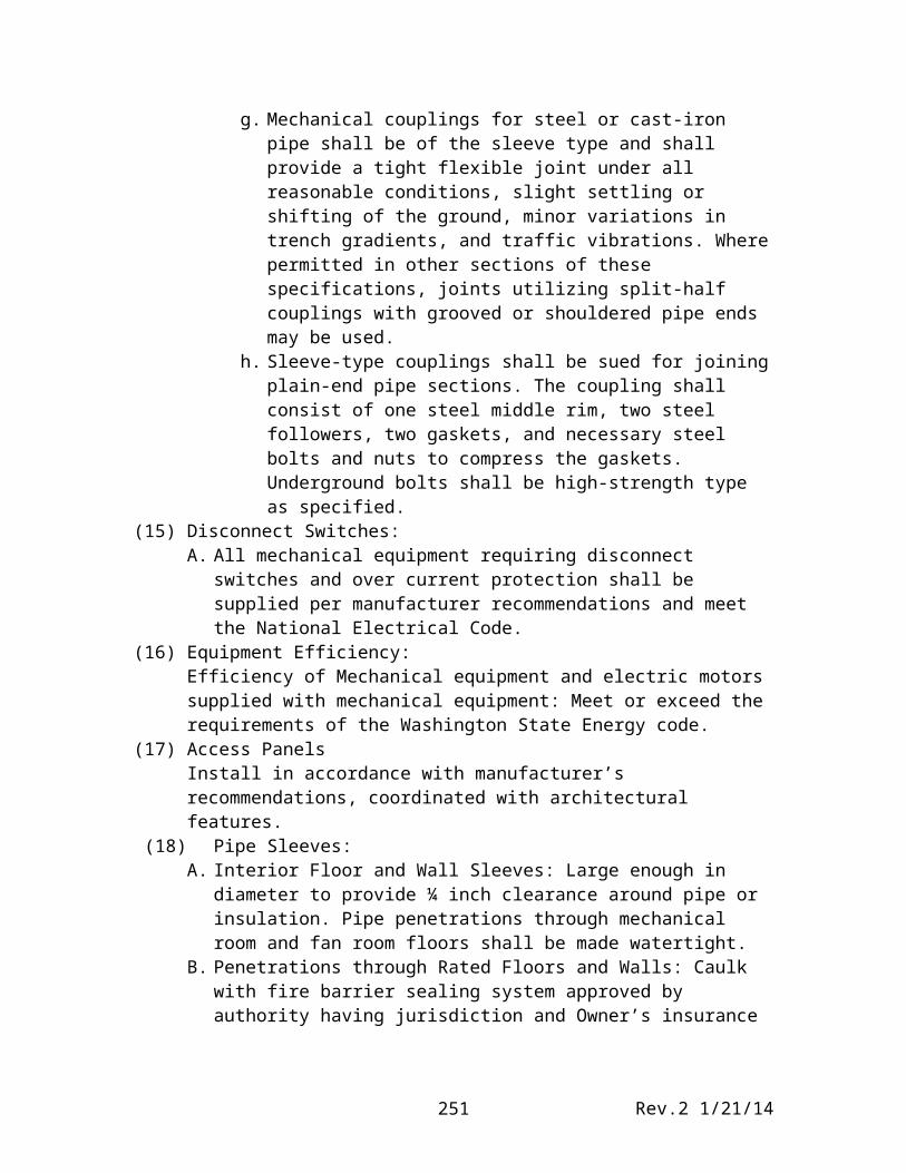
g. Mechanical couplings for steel or cast-iron pipe shall be of the sleeve type and shall provide a tight flexible joint under all reasonable conditions, slight settling or shifting of the ground, minor variations in trench gradients, and traffic vibrations. Where permitted in other sections of these specifications, joints utilizing split-half couplings with grooved or shouldered pipe ends may be used.
h. Sleeve-type couplings shall be sued for joining plain-end pipe sections. The coupling shall consist of one steel middle rim, two steel followers,
Rev.2 1/21/14246
two gaskets, and necessary steel bolts and nuts to compress the gaskets. Underground bolts shall be high-strength type as specified.
(15) Disconnect Switches:A. All mechanical equipment requiring disconnect switches and over current
protection shall be supplied per manufacturer recommendations and meet the National Electrical Code.
(16) Equipment Efficiency:Efficiency of Mechanical equipment and electric motors supplied with mechanical equipment: Meet or exceed the requirements of the Washington State Energy code.
(17) Access PanelsInstall in accordance with manufacturer’s recommendations, coordinated with architectural features.
(18) Pipe Sleeves:A. Interior Floor and Wall Sleeves: Large enough in diameter to provide ¼ inch
clearance around pipe or insulation. Pipe penetrations through mechanical room and fan room floors shall be made watertight.
B. Penetrations through Rated Floors and Walls: Caulk with fire barrier sealing system approved by authority having jurisdiction and Owner’s insurance underwriter, with rating equal to floor or wall penetrated.
C. Exterior Wall Sleeves: Large enough to allow for caulking and made watertight. Caulking shall be from outside. Secure sleeves against displacement.
D. On-Grade floor Sleeves: Same as exterior wall sleeves, caulked from inside.E. Layout: Layout work in advance of pouring of slabs or construction of wall
and furnish and set inserts and sleeves necessary to complete the work.F. Coordination: Cutting and patching required as a result of lack of coordination
of this operation shall be at no additional cost.(19) Floor, Wall and Ceiling Escutcheon Plates:
A. Install on piping passing though finished walls, floors, ceilings, partitions and plaster furring. Escutcheon plates shall completely cover opening around pipe.
B. Secure wall and ceiling plates to pipe or structure.C. Plates shall not penetrate insulation vapor barriers.D Plates not required in unfinished spaces.
(20) Piping Markers:A. Install in accordance with ANSI A13.1 or the following, whichever is more
stringent, apply labels or letters after completion of pipe cleaning, insulation, painting, or other similar work, as follows.1. Every 20 feet along continuous exposed lines.2. Every 10 feet along continuous concealed lines.3. Adjacent to each valve and stub-out for future.4. Where pipe passes through a wall, into and out of concealed spaces.5. On each riser.6. On each leg of a “T”.7. Locate conspicuously where visible.
Rev.2 1/21/14247
B. Further apply labels or letters to lower quarters of the pipe on horizontal runs except where view is not obstructed on the upper quarters and pipe is normally viewed from above.
(21) Mechanical Piping and Supporting Devices:A. General: Fabricate and install piping and tubing in accordance with ASME
B31.9 or the Uniform Plumbing Code as applicable, the drawings, and this specification.1. Install all piping systems in accordance with manufacturer’s
recommendations. Provide pipe racks, pipe stands, trapeze hangers, etc., as required.
2. Provide adjustable hangers complete with inserts, adjusters, bolts, nuts, swivels, all-thread rods, etc., except where specified otherwise, for all pipes.
3. Do not use wire or perforated metal to support piping.4. Except as otherwise indicated for exposed continuous pipe, runs, install
hangers and supports of same type and style as installed for adjacent similar piping.
B. Foundations and Supports:1. Provide where shown on drawing, or as specified, and per manufacturer’s
installation instructions.C. Pipe Supports:
1. Suspended Piping: support piping at each change in direction. Support piping on either side of control valves, pumps, at equipment connections, and wall penetrations so that piping is independently supported.
2. Piping shall be independently supported form pipe hangers and shall not be laid through trusses, or supported from other piping or ductwork.
3. Riser piping shall be supported at the top and bottom of the riser with intermediate supports as required. Riser piping shall not depend on a friction clamp for load bearing support.
D. Vertical Piping:1. Pipe supports shall hold a piping away from wall unless otherwise
approved.2. Riser clamps to be directly under fitting (mechanical couplings not
included) or welded to pipe.3. Risers to be supported at each floor penetration.4. Provide structural steel supports at the base of pipe risers. Size supports to
carry all forces exerted by piping system when systems are in operation.E. Horizontal Piping:
1. Support within two feet at each change in direction.2. For cast iron no-hub piping and fitting assemblies less than 5’-0” long,
provide hangers at each pipe end and fittings.F. Building Attachments:
1. Fastening or attaching to deck structure is prohibited. Support all piping from primary structural members, beams, joists, or provide intermediate supporting members between joists or beams.
Rev.2 1/21/14248
2. Provide all additional structural steel angles, channels, or other intermediate members required to support piping where structures do not occur as required for proper support.
3. Arrange supports to prevent eccentric loading of joists and joist girders. Locate supports at joist panel points.
(22) Cleaning and Adjusting:A. General: Thoroughly clean Mechanical and plumbing equipment, fixtures,
piping and ductwork of stampings and markings (except those required by codes), iron cuttings and other refuse. Clean plenums and equipment casings of debris and small particles of rubbish and dust before installing and making final duct connections. Provide temporary filters for all equipment with filters, replace with new filters after construction activities in building are complete.
B. Painted Surfaces: Clean scratched or marred factory finished and painted surfaces of rust or other foreign matter and paint with matching color industrial enamel or manufacturer supplied touch up paint.
C. Adjusting: After mechanical equipment has had minimum of thirty days of operation, lubricate and grease all equipment. Re-tighten belts to proper tension. Adjust fans, valves, control valves and other miscellaneous equipment requiring adjustment to setting indicated or directed.
D. Additional requirements are specified under specific sections of this Division.(23) Painting:
A. Equipment Room and Finished Areas:1. Insulation: Apply PVC jacket, see Section 152502. hangers, un-insulated piping, miscellaneous ironwork, structural steel
stands, un-insulated tanks, equipment bases: Paint one coat of black enamel.
3. Steel valve bodies band bonnets: One coat of black enamel4. Brass valve bodies: Not painted.5. Equipment: One coat of grey machinery enamel. Do not paint nameplates
or factory finished equipment.6. Grilles, Diffusers, and Registers: Paint sheet metal and visible ductwork
behind grilles, diffusers, and registers flat black.B. Refer to Architectural Specification Section and individual Sections of
Division 15 for supplemental and additional painting requirements.C. Finish exterior mechanical equipment, materials, devices, and construction
with finish type and color as selected by Architect, submit color palette for approval.
D. Finish interior mechanical equipment, materials, devices and construction with finish type and color as selected by Architect, submit color palette for approval.
Rev.2 1/21/14249
Section 15250, Mechanical Insulation
(1) Description: This section describes piping insulation and ductwork insulation, both internal and external.
(2) Pipe Insulation:A. Acceptable Manufacturers:
1. Where Manvivlle/Schuller is the only manufacturer indicated, equivalent products by Owens-Corning maybe furnished.
B. Glass Fiber, All-Purpose Jacket (850 F Temp. Limit): Preformed glass fiber one piece, with vapor barrier jacket, thermal conductively less than .25 at 100 deg F. Shuller Micro-Lok Ap-T Plus.
C. Glass Fiber, Blanket: One pound density, with vapor barrier jacket. Schuller with “FSK” jacket.
D. Preformed Pipe coverings: one-piece heavy duty PVC insulated pipe jacketing and pipe fitting covers. Schuller Zeston 2000/300 PVC assembled with Perma Weld solvent.
1. Where Manville/Schuller in the only manufacturer indicated, equivalent products by Owens-Corning may be furnished.
B. External Insulation: Glass fiber blanket, ¾ lb./cu. ft. with vapor barrier jacket. Schuller “Microlite” with “FSK” jacket.
C. Insulation thermal conductivity shall be a minimum of k = 0.24.D. Vapor barrier is required on the exterior of the insulation to protect it form
condensation.E. The vapor barrier shall be continuous with all joints sealed and having a perm
rating 0.5 perm.(4) Duct Insulation, Internal:
A. Acceptable Manufacturers: Where Schuller is the only manufacturer indicated, equivalent approved products by Owens-Corning may furnished no exceptions.
B. Rectangular Duct Internal Liner: Mat-faced density 1-1/2 lb./cu. ft. minimum, antimicrobial acoustical duct blanket, Schuller “Linacousitc” duct liner.
C. Round Duct Internal Liner: Schuller Spiracoustic and Spriacoustic Plus round duct liner with anti-microbial airstream coating. Minimum thermal conductivity of k = 0.24.
D. Adhesive: Benjamin Foster 85-20, Tuff-Bond or equivalent.E. Weld or Stick Pins: Duro Dyne with NC-I nylon stop clips, Grip-Nail, Gemco,
Tuff-Bond or equivalent.F. Sealant: Schuller Super Seal or equal: All joints shall be sealed so that
condensation within the insulation will not occur.(5) Pressure Sensitive Tape:
A. Acceptable Manufacturers” Where Nashua tapes are indicated, equivalent products by other insulation manufacturers specified in this section are acceptable.
Rev.2 1/21/14250
B. Pipe Insulation:1. Glass fiber, all-purpose jacket: Nashua Type 3572. Glass fiber blanket: Nashua Type FSK3. Preformed pipe covering: Nashua type ASJ
C. Duct Insulation1. External insulation: Nashua type FSK
(6) Pipe Insulation:A. Applied Locations:
1. Potable cold Water above Ground Insulation: Thickness of ½ inch on run-outs up to 2-inch diameter. Thickness of ½ inch on piping up to 2 inch diameter, thickness of 1 inch on pipe sizes above 2-inch diameter. Glass fiber with all-purpose jacket.
2. Potable Hot Water Above Ground Insulation: Thickness of ½ inch on run-outs, thickness of 1 inch on pipe sizes up 2-inches diameter, thickness of 1-1/2 inches on pipe sizes 2-1/2 inches diameter and larger; Glass fiber will all purpose jacket.
3. Heating Hot Water Supply and Return Piping Insulation: Thickness of 1.5 inches on piping up to 8 inches in diameter, runouts to individuals terminal units less than 12 feet in length may be 0.5 inches thick. Exposed piping shall have red PVC jacketing.
4. Chilled Water Supply and Return Pipe Insulation: Thickness of 0.5 inches on piping 1 inch diameter and less, 0.75 inches on piping greater than 1 to 2 inches, and 1.0 inches on piping greater than 2.0 inches in diameter. Runouts to individual terminal units not exceeding 12 feet in length may have 0.5-inch thick insulation. Exposed piping shall have blue PVC jacketing. Exterior chilled water piping shall have RPR- Z embossed aluminum jacketing (0.016”, T-3003 H14)
5. Rain Water Leaders/Roof Drain Piping Insulation: 0.5 inches minimum thickness, or as recommended by insulation manufacturer for application.
B. Installation, Piping Insulation:1. General Requirements
a. Installed in accordance with manufacturer’s recommendations.b. Install insulation over clean, dry surfaces only.c. No staples are to be used on runs where electric heat trace exists.d. Insulation kits shall be installed with all joints butted tightly to
minimize crevices.e. Install pre-formed PVC pipe covering on all interior insulation
wherever piping is not enclosed in a wall or ceiling cavity. Install colored PVC jacketing at all air handling units and equipment to a height of 10 feet above the floor in mechanical attics.
2. Piping: Butt side and end joints tightly and paste factory applied jacket at longitudinal and circumferential joints. Finish and seal exposed ends neatly with the jacket material, glass cloth and mastic, or use preformed pipe coverings.
3. Applicationa. Slip pipe insulation onto pipe and seal butt joints.
Rev.2 1/21/14251
b. Where slip on technique is not possible, slit insulation, apply to pipe, and seal seam and joints.
c. Piping Specialties: Fully insulate all components of all piping systems. Items requiring access for service or repair (pumps, valves, strainers, etc.) shall be provided with removable, reusable, insulation pads, EJ Bartells, or equal.
d. Install embossed aluminum jacketing (T-3003 H14, 0.020 inches thick) on exterior chilled water pipe, RPR or equal.
(7) Duct Insulation:A. Ducts shall be insulated with the minimum thermal resistances as follows
unless more stringent levels are listed herein or noted on drawings.1. Supply, return, exhaust and pressure relief ducts within conditioned space,
R-3.3. Exhaust and relief ducts outside conditioned space, R 3.3.2. Supply and return ducts in concrete or in ground, R-5.3.3. Supply or return ducts outside conditioned space, R-7.
The applied locations are:1. Supply and return ductwork outside the building: Internally lined.2. Supply and return ductwork inside the building: Internally lined unless
noted otherwise on drawing.a. Round supply and return duct 18 inches in diameter and smaller may
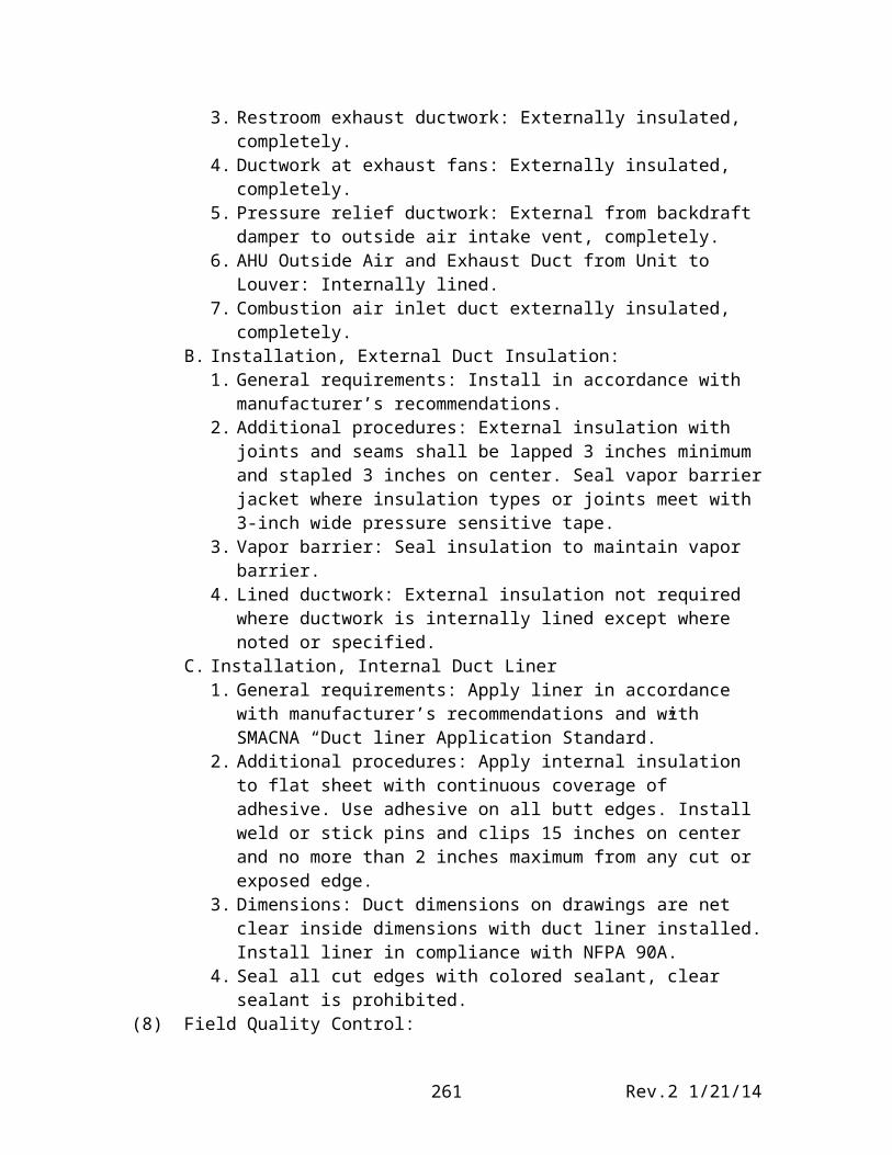
be externally insulated, unless noted otherwise.3. Restroom exhaust ductwork: Externally insulated, completely.4. Ductwork at exhaust fans: Externally insulated, completely.5. Pressure relief ductwork: External from backdraft damper to outside air
intake vent, completely.6. AHU Outside Air and Exhaust Duct from Unit to Louver: Internally lined.7. Combustion air inlet duct externally insulated, completely.
B. Installation, External Duct Insulation:1. General requirements: Install in accordance with manufacturer’s
recommendations.2. Additional procedures: External insulation with joints and seams shall be
lapped 3 inches minimum and stapled 3 inches on center. Seal vapor barrier jacket where insulation types or joints meet with 3-inch wide pressure sensitive tape.
3. Vapor barrier: Seal insulation to maintain vapor barrier.4. Lined ductwork: External insulation not required where ductwork is
internally lined except where noted or specified.C. Installation, Internal Duct Liner
1. General requirements: Apply liner in accordance with manufacturer’s recommendations and with SMACNA “Duct liner Application Standard.”
2. Additional procedures: Apply internal insulation to flat sheet with continuous coverage of adhesive. Use adhesive on all butt edges. Install weld or stick pins and clips 15 inches on center and no more than 2 inches maximum from any cut or exposed edge.
Rev.2 1/21/14252
3. Dimensions: Duct dimensions on drawings are net clear inside dimensions with duct liner installed. Install liner in compliance with NFPA 90A.
4. Seal all cut edges with colored sealant, clear sealant is prohibited.(8) Field Quality Control:
A. Field Tests: Testing of systems shall have been completed and systems approved prior to applying insulation.
B. Existing Systems:1. Repair existing insulation damaged during installation of work. 2. Make neat connections where new and existing insulation meet.3. Where existing piping, ductwork or equipment is removed, cover existing surfaces neatly to match existing.
C. Accessibility: Provide removable insulation sections to cover parts of equipment which must be opened periodically for maintenance; including metal vessel covers, fasteners, valves, flanges, frames, and accessories. Do not insulate boiler manholes, handholes, cleanouts, ASME stamp, and manufacturer’s nameplates. Provide neatly beveled edge at interruptions of insulation.
Rev.2 1/21/14253
Section 15300, Fire Protection
(1) Work included:A. Work includes design and construction of fire protection system extensions to
all Pasco School District No. 1 campus buildings and building additions constructed or revised by this project.
B. Contract requirements of Division 1 apply to all work in this Section.C. Provide phased installation of the work in the section in accordance with the
requirements of Section 01100. Each Phase shall be fully functional and ready for occupancy.
(2) Quality Assurance:A. Regulatory Requirements:
1. Comply with all applicable city, county, and state codes and ordinances. In case of conflict with drawings or specifications, the codes and ordinances govern. Arrange and pay for all permits and inspections required.2. Authorities Having Jurisdiction:
a. Local Fire and Building Departmentsb. Country Fire Marshalc. State Fire Marshald. Owner’s Insurance Company
B. Design Criteria:1. Provide complete fire protection system as indicated and required. Design
and install entire system in accordance with indicated codes, standards and regulations. Provide all standard accessories necessary for complete and operable system, including complete sprinkler riser connections and/or extension of the existing on-site fire sprinkler systems and infrastructure, fire department connection, inspectors test connections, sprinklers, piping, 911 system tie-in, fire station alarm tie-in, water movement sensor tie-in, and smoke detection system tie-in.
2. Hazard Classification:In accordance with NFPA -13.3. Application: All areas including electrical and mechanical rooms,
concealed spaces at ceilings, under stages, attic spaces, exterior canopies and overhangs, Elevator Equipment Room and shaft, water wall with all required non-combustible baffles at stage proscenium, and other areas as required per NFPA – 13.
4. Piping Design: Hydraulically designed.5. Water Supply: Obtain latest water supply engineering test data prior to
design. Use 10% safety margin in system design.6. Fire protection during construction shall be in accordance with NFPA-13.7. The sprinkler plans and hydraulic calculations shall be prepared by or
under the direct supervision of and stamped by a Washington State Certified Level 3 Fire Protection Designer, verifying compliance with NFPA – 13, or as approved by the authority having jurisdiction.
8. Locate fire protection riser in Room (to be determined) as required or directed.
Rev.2 1/21/14254
C. Standards:1. National Fire Protection Association, NFPA – 13, Installation of Sprinkler
Systems.2. Factory Mutual (FM) Approval Guide.3. Underwriters’ Laboratories Fire Protection Equipment List
D. Qualifications: The Sprinkler Contractor shall design, supply and install the entire sprinkler system; the use of subcontractors to the Sprinkler contractor is not acceptable. The Sprinkler Contractor shall possess a valid sprinkler contractor license from the State of Washington. Use workers skilled in this trade.
E. Coordination with Other Trades:1. Carefully check construction documents before designing or installing any
of this work. Consider the work of all other trades, and coordinate this work with that of the Sheet Metal, Plumbing, and Electrical Contractors so that the best arrangement of all equipment, piping, conduit, ducts, etc., can be obtained.
2. Identify any points of conflict between this work and that of the other trades, so that the conflict may be properly adjusted. Work installed by this Contractor which interferes with the work of other trades shall be removed and re-installed at the Contractor’s expense. It shall be understood that no change orders to the Contract will be permitted to accomplish the above results.
F. Building Coordination: Arrange pipe routing to minimize impact on the interior decorative finishes; coordinate with and obtain approval from A/E. Clearly note exposed fire protection piping in finished areas on submittal drawings. The Architect reserves the right to reject exposed fire protection piping not clearly noted as such on drawings. Rejected piping shall be removed and reinstalled within building construction, at no additional cost to the Owner.
(3) Submittals:A. General: Submit in accordance with Section 1300 and the following. Do not
submit until approved by all Authorities Having Jurisdiction.B. Product Date:
1. Pipe and Fittings.2. Valves.3. Dry Pipe and Wet Pipe Alarm Valves and Appurtenances.4. Sprinklers.5. Supports and Appurtenances.6. Backflow Preventer.7. Fire Department Connection.8. Alarm and Signal Devices.
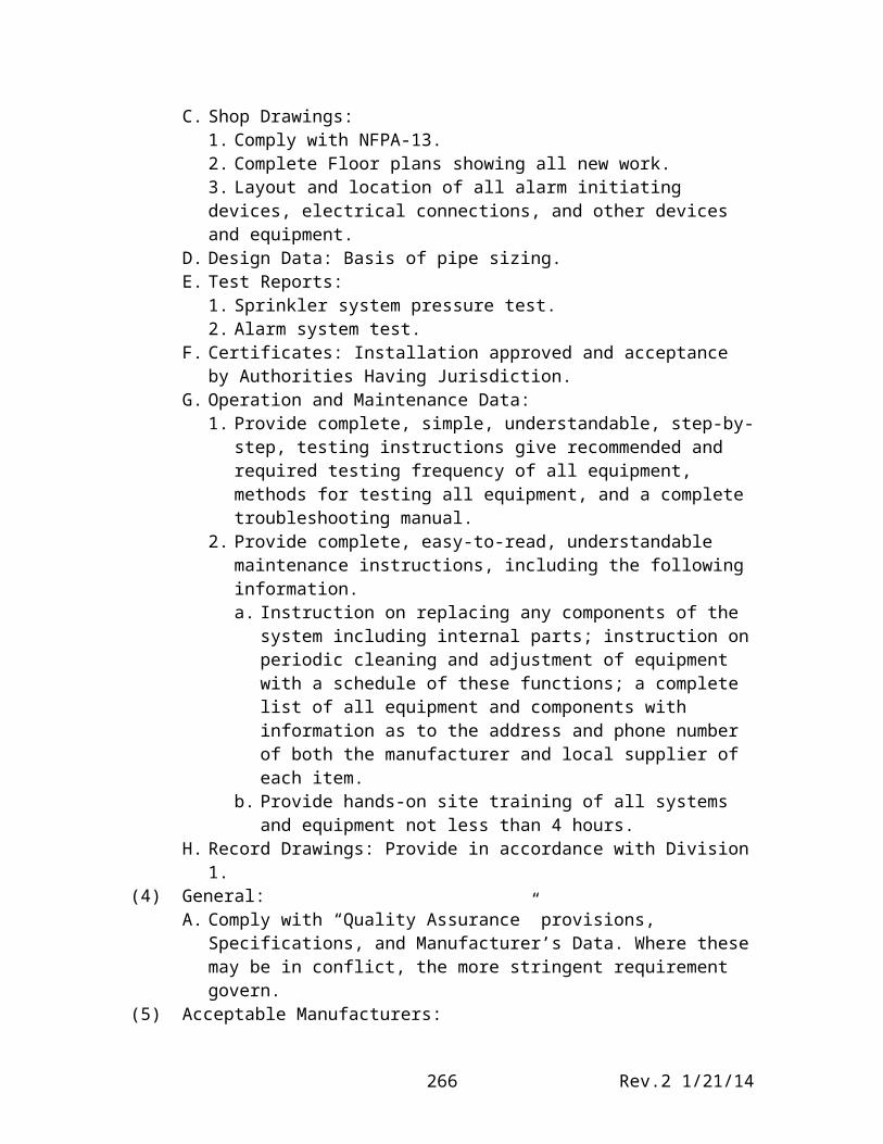
C. Shop Drawings:1. Comply with NFPA-13.2. Complete Floor plans showing all new work.3. Layout and location of all alarm initiating devices, electrical connections, and other devices and equipment.
Rev.2 1/21/14255
D. Design Data: Basis of pipe sizing.E. Test Reports:
1. Sprinkler system pressure test.2. Alarm system test.
F. Certificates: Installation approved and acceptance by Authorities Having Jurisdiction.
G. Operation and Maintenance Data:1. Provide complete, simple, understandable, step-by-step, testing
instructions give recommended and required testing frequency of all equipment, methods for testing all equipment, and a complete troubleshooting manual.
2. Provide complete, easy-to-read, understandable maintenance instructions, including the following information.a. Instruction on replacing any components of the system including
internal parts; instruction on periodic cleaning and adjustment of equipment with a schedule of these functions; a complete list of all equipment and components with information as to the address and phone number of both the manufacturer and local supplier of each item.
b. Provide hands-on site training of all systems and equipment not less than 4 hours.
H. Record Drawings: Provide in accordance with Division 1.(4) General:
A. Comply with “Quality Assurance” provisions, Specifications, and Manufacturer’s Data. Where these may be in conflict, the more stringent requirement govern.
(5) Acceptable Manufacturers:A. Listed manufacturers with products equivalent to specific product indicated (if
any) are acceptable; A/E is sole judge of equivalency.B. Non-listed manufacturers may be considered by the A/E if request is received
(6) Materials:A. Use only new, unused material of first-class construction, designed and
guaranteed to perform service required, approved by NFPA, FM, and UL for the intended purpose.
B. Above-Grade Pipe and Fittings:
Rev.2 1/21/14256
1. Pipe: Comply with NFPA-13 and 14; black steel, ASTM A53, A135, or A795. For pipe other than Schedule 40 or Schedule 10, provide as UL listed and FM approved.
2. Fittings:a. UL listed for sprinkler service and for the specific type of pipe.b. Provide minimum 125 psi class.c. Two inches and smaller: 150-pound black malleable iron, screwed,
ANSI B16.3 and ASTM A197.d. 2-1/2 inches and larger: Grooved joint fittings, malleable iron ASTM
A47 or ductile iron ASTM A536 bodies; flanged fittings, forged steel or ductile iron.
e. Grooved Joint Couplings: UL listed for sprinkler service: malleable iron ASTM A47 or ductile iron ASTM A536 housing; chlorinated butyl gasket; nuts and bolts ASTM A183; minimum 110,000 psi tensile.
f. Provide galvanized steel pipe and fittings for drain lines.C. Underground 4-inch to 8-inch:
1. Pipe: ductile iron, cement lined, Class 50 or 51, ANSI A21.51 and AWWA C151, 350 psi rated water working pressure.
2. Fittings: Ductile iron, cement lined, ANSI A21.10 and AWWA C110, 250 psi rated water working pressure.
3. Joints: AWWA C111, mechanical or Tyton, in general, flanged at connections to valves and equipment.
D. Components:1. Valves:
a. General: UL and FM approved, minimum 175 psi class. b. Gate Valves:
1) Two inches and smaller: 175-pound UL-FM bronze gate, solid wedge disc, OS&Y, screwed.
2) 2-1/2 inches and larger: 175-pound UL-FM iron body gate, solid wedge disc, OS&Y, flanged
c. Wet Pipe Alarm Valve and Appurtenances: 175 psi UL-FM cast iron body; cast bronze clapper, clamp ring, and valve seat; water pressure gauges, pressure operated relief valve, alarm test valve, emergency release, and drain valves.
d. Dry Pipe Alarm Valve and Appurtenances: 175 psi UL-FM cast iron differential type alarm valve and trim, maintenance air compressor, air maintenance device, accelerator, anti-flood device, and alarm devices. Coordinate power and alarm requirements with work of Division 16.
2. Sprinklers:a. General: Provide sprinklers of type required by Authorities Having Jurisdiction for service indicated, listed by UL or FM. In no case use sprinklers rated less than 50 F higher than anticipated ambient temperature.b. Type: Sprinklers Installed in finished ceilings shall be concealed plate type, white finish. Sprinklers installed above finished ceilings or
Rev.2 1/21/14257
areas without ceilings shall be upright or Pendant type, rough bronze finish.c. Provide shields where sprinklers are subject to damage from student activities; comply with NFPA-13, and Owner requirements.d. Head Type, Sidewall: Freeze-proof design.e. Sprinkler Cabinet: Provide with the required number of sprinklers of all ratings and types installed and a sprinkler wrench, located adjacent to the riser.
3. Pipe Supports: Provide metal pipe supports, flexible connections, sway braces, hangers, clamps and other pipe support items in accordance with NFPA-13. Provide pipe hangers and braces seismically designed per NFPA-13. Do not use “C-Clamp” hangers unless provided with integral seismic retaining strap.
4. Identification Signs: Provide enameled signs for all drain valves, test valves, control valves and alarm valves indicating their use.
5. Miscellaneous Connections and Fittings: Provide drains, and other items in accordance with NFPA-13.
6. Vertical Backflow Preventer: Provide where required.7. Fire Department Connection: Bright chrome finish Potter-Roemer 5020
Series 13 double-clappered Siamese; provide the coupling connection in accordance with NFPA-194; install drip connections.
8. Alarm and Signal Devices:a. Air Pressure Switch (Dry Pipe System): Differential type installed and
connected in such a manner that loss of air pressure due to fusing of a single sprinkler head will automatically energize the fire alarm system; equip with two contacts of the normally open type.
b. Water flow switch (Wet Pipe System): Vane-type flow switch, installed and connected in such a manner that flow of water equal to or greater that than from a single head will automatically energize the fire alarm system; equip with two contacts of the normally open type. Provide field adjustable time delay, adjustable form 0-60 seconds.
c. Valve Monitor Switches: 115 VACd. Pressure Gages: 3-1/2- inch dial, phosphor bronze tube, brass socket,
A. Extend fire protection main form 5 feet outside of the building to fire riser. (verify location)
B. Install, apply, erect, and perform the work in accordance with “Quality Assurance” provisions, specifications and manufacturer’s installation instructions and direction. Where these may be in conflict, the more stringent requirements govern.
C. Cooperate with other trades to insure adequate space for piping placement. All fire protection piping and equipment shall be concealed except in areas where not feasible and fire protection riser room. Clearly annotate drawings indicating exposed piping on submitted drawings.
D. Review plans, specifications, and shop drawings of other trades to coordinate work.
E. Install in strict accordance with reviewed shop drawings.F. Do not begin installation until approvals are received from Authorities
having jurisdiction and approved submittals are available on site.G. Service Interruptions: Obtain advance approval for PSD No.1 and the local
fire department.H. Mount exterior alarm bell on exterior wall of building; obtain A/E approval of
location.I. Mount fire department, connection on exterior wall of building or in site work
above grade; obtain A/E approval of location.(11) Installation of Piping and Sprinklers:
A. Offset, crossover and otherwise route piping to install system in available space.
B. Install, accurately cut steel piping to measurements established at the jobsite, free of fins and burrs. Install using full pipe lengths; random pipe lengths jointed by couplings will not be accepted. Clean all piping before placing in position and maintain in a clean condition. Work into place without springing or forcing. Support pipe from structural members only. For pipe joints, provide full-cut threads. Apply pipe compound to male threads only. Connect joints so that not more than three threads on the pipe remain exposed.
C. Install drips and drains where necessary to discharge to standard interior floor drains or sinks, or to exterior splash blocks. In no case shall a direct connection be made to any of the sewer systems. Install dirt legs and drain valves at low pints of all piping to permit complete drainage of system without disconnection of any piping.
D. Provide piping system completely braced to withstand damage from earthquakes. Install flexible couplings and earthquake bracing in accordance with NFPA-13.
Rev.2 1/21/14259
E. Provide chrome plated escutcheon plates at exposed pipe penetrations of ceilings, floors and walls.
F. Install sprinkler head at center of ceiling grid pattern in suspended tee bar ceilings. No exceptions.
G. Hold piping as tight to structure as possible. In general, run piping in areas without ceilings parallel to building elements.
H. Inspector Test Valves: Install test valve at the highest and most hydraulically remote part of the system in relation to the riser assembly. Locate test valves such that they are conveniently accessible from the floor. Obtain A/E approval of locations. Pipe to building exterior with splash block, or to floor drain or janitor’s sink within building.
(12) Fire Detection and System Actuation:Building Fire Alarm System Interface: Integrate the operation of the sprinkler system into the Building Fire Alarm Systems.A. Coordinate with fire alarm system work of Division 16; provide interlocks as
required.B. Provide water flow switch for wet pipe riser. Provide air pressure switch for
dry pipe alarm valve riser. Provide valve monitor switches for valves, including post indicator valves.
(13) Field Quality Control:A. Hydraulically test sprinkler piping in accordance with NFPA-13 and NFPA-
14 requirements. No leakage will be permitted in piping. Prior to performing the pressure test, notify the Authorities Having Jurisdiction, the A/E and PSD No.1 of the pressure test schedule; give notice at least two weeks prior to tests.
B. Test complete alarm system, including control and signal circuits:1. Operate each signal initiating device.2. Test operation of all features of the system under normal operation.3. Test all supervisory features of the system.
C. Give one week notice and arrange for field tests and inspections by the local authorities, including paying for inspection fees and securing permits for same.
D. Approval and Acceptance: After the sprinkler system has been completely installed, pressure tested, and all substantial completion review items corrected, obtain the approval and acceptance of the system by the Authorities Having Jurisdiction, in accordance with NFPA-13. Retests due to failure to meet he design requirements shall be at the Sprinkler Contractor’s expense.
Rev.2 1/21/14260
Section 15400, Plumbing Piping
(1) Description: Provide piping, pipe fittings, valves, supports and anchors, and incidental related items as required for complete plumbing piping system.
(2) Applicable Standards:A. Piping material and installation shall meet requirements of the IPC.B. Chlorination of domestic cold and hot water piping shall be in accordance
with County and State health requirements.Quality AssuranceA. Pipe Cleaning: Should any pipe be plugged or should foaming of water
systems occur, the piping shall be disconnected, cleaned, and reconnected without additional cost to PSD No. 1.
B. Damage to the building or systems resulting from failure to properly clean the system shall be corrected without expense to PSD No.1.
(3) Acceptable Manufacturers:A. Valves: Where only Jenkins figure numbers are listed, equivalent products by
Stockham, Milwaukee, or other recognized manufacturer of equal quality are acceptable.
(4) Cast Iron Soil Pipe, Service Weight:A. General: A code approved hubless system conforming to Cast Iron Soil Pipe
Institute Standard 301.B. Pipe and Fittings: Service weight hubless cast iron conforming to ASTM A
74. C. Couplings:
1. Above grade: “C.I. No Hub” band type coupling consisting of stainless steel clamp and shield assemblies, with a neoprene sealing sleeve (ASTM-C-564)
D. Service:1. Sanitary sewer and waste to 5 feet outside building line.2. Vent piping 2 inches and larger.3. Rain leaders and overflows to 5 feet outside building line.
(5) Ductile Iron Water Pipe:A. Pipe: Ductile iron pipe, Class 52, conforming to ANSI A21.51.B. Fittings: Class 150 “Bolt Tite” mechanical joint type complete with gaskets,
bolts and nuts; or “Tyton” for joints employing a single gasket for the joint seal with Bell-and-Spigot pipe.
C. Service:1. Buried water mains from 5 feet outside building line.
(6) Galvanized Steel Pipe:A. Pipe: Schedule 40 conforming to ASTM A120.B. Fittings: 150 lb. screwed malleable iron on 2-1/2 inches and below, 150 lb.
flanged above; provide screw-on flanges for joining sections of pipe. Coated cast iron recessed drainage fittings on waste and vent in tight spaces.
C. Service:1. Miscellaneous indirect waste piping.
Rev.2 1/21/14261
2. At Contractor’s option, waste and vent piping 1-1/2 inches and under, above grade.
(7) Copper Pipe:A. Pipe: Hard-drawn or soft copper tubing, Class L or K, or Type DWV per
Note: Alternate mechanical type fittings may be considered for small diameter (1 inch nominal and under) Type L, pipe above grade. Submit for approval.
C. Service:1. Domestic hot and cold water piping below ground, Type K, soft.2. Domestic hot and cold water piping above ground, Type L, hard-drawn.3. Trap priming lines, Type K, annealed.4. Drain, Waste, and Vent above ground, Type DWV.
C. 2 ½ inches and larger: Iron Swing Check: Iron body, horizontal swing, bolted bonnet, bronze mounted, flanged, re-grinding bronze renewable disc and seat ring, 125 psi rating, Jenkins 624.
(11) Ball Valves:A. Bronze Ball: Bronze body, cap , stem and ball. One-quarter turn handle, two-
piece construction, PTFE-N seats, packing and O-rings, Milwaukee BA Series, or equal product by Hammond, no exceptions.
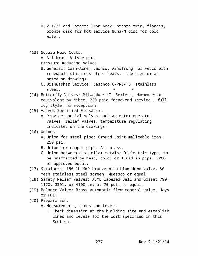
(12) Globe Valves:A. 2-1/2’ and Larger: Iron body, bronze trim, flanges, bronze disc for hot service
Buna-N disc for cold water.
Rev.2 1/21/14262
(13) Square Head Cocks:A. All brass V-type plug.Pressure Reducing ValvesB. General: Cash-Acme, Cashco, Armstrong, or Febco with renewable stainless
steel seats, line size or as noted on drawings.C. Dishwasher Service: Caschco C-PRV-TB, stainless steel.
(14) Butterfly Valves: Milwaukee “C” Series”, Hammond, or equivalent by Nibco, 250 psig “dead-end service”, full lug style, no exceptions.
(15) Valves Specified Elsewhere:A. Provide special valves such as motor operated valves, relief valves,
temperature regulating indicated on the drawings.(16) Unions:
A. Union for steel pipe: Ground Joint malleable iron. 250 psi.B. Union for copper pipe: All brass.C. Union between dissimilar metals: Dielectric type, to be unaffected by heat,
cold, or fluid in pipe. EPCO or approved equal.(17) Strainers: 150 lb SWP bronze with blow down valve, 30 mesh stainless steel
screen, Muessco or equal.(18) Safety Relief Valves: ASME labeled Bell and Gosset 790, 1170, 3301, or 4100 set
at 75 psi, or equal.(19) Balance Valve: Brass automatic flow control valve, Hays or FDI.(20) Preparation:
A. Measurements, Lines and Levels1. Check dimension at the building site and establish lines and levels for the
work specified in this Section.2. Establish all inverts, slopes, and elevations by instrument, working from
an established datum point. Elevation markers and line shall be provided for use to determine that slopes and elevations are in accordance with Drawings and Specifications.
3. Use established grid and area lines for locating trenches in relation to building and boundaries.
(21) Piping Installation:A. Install all plumbing in compliance with the International Plumbing code.B. Install unions in all non-flanged piping connections to apparatus and adjacent
to all screwed control valves, traps, and appurtenances requiring removal for servicing, so located that piping may be disconnected without disturbing the general service.
C. Support all piping independently at apparatus so that its weight shall not be carried by the equipment.
D. Underground Water System: Provide concrete thrust blocks, prior to testing pipe, at changes in direction. Block size as require for types of fittings involved. Comply with City of Pasco standards.
E. Dielectric Fittings: Provide dielectric couplings, unions or flanges between dissimilar metals. Additionally, provide dielectric couplings as required to isolate catholically protect piping and equipment. Fittings shall be suitable for the pressure and temperature to be encountered. Provide insulating couplings
Rev.2 1/21/14263
or unions to prevent electrolysis between dissimilar metals, when use of dissimilar metals cannot be avoided in system.
F. Vent Through Roof Location: Provide flashing and seal as recommended by roofing supplier for particular application or complete per drawing detail.
G. Trim: Provide escutcheons at each point where pipe or fittings enter wall at fixture.
H. Provide line size strainers upstream of all pressure reducing valves and backflow prevention devices, complete with stainless steel strainer and blow down valve capped.
(22) Piping Joints:A. Screwed Joints: Ream pipe ends. Apply dope or tape to male thread only.
Brass joints shall be made with Teflon tape only. Make up fitting with not over two thread showed beyond the fitting ends. Make junctions of galvanized pipe to cast iron with tapped spigots or half couplings screwed to the end of galvanized pipe to form a spigot end.
B. Solder Type Joints: Clean the copper tubing and fittings thoroughly with emery cloth or steel wool before applying the flux. The copper tubing shall have all burrs removed, be reamed to full bore, and be true and round for all joints. Apply heat uniformly to secure penetration of the rod. Leave a full bead around the entire circumference of the joint to show proper penetration and sealing. Use of lead-bearing solder on domestic/potable water supply piping is prohibited. Use ASTM B32 95-5 Tin Antimony.
(23) Installation of Valves:A. Provide valves at connections to equipment where shown or required for
equipment isolation.B. Install all valves accessible and same size as connected piping.C. Provide separate support for valves where necessary.
(24) Applied Locations of Valves:A. In piping two inches and smaller, Hot and Cold Water:
1. Bronze swing check valves.2. Ball valves.
B. In piping 2-1/2 inches and larger, hot and cold water:1. Iron/bronze butterfly valves.2. Iron gate valves.3. Iron globe valves.4. Iron swing check valves.
C. Drain Valves: Provide hose end drain valves at water system low points and high points where system cannot be drained through fixtures or equipment.
D. Automatic balancing valves in hot water recirculation lines as required to balance flow throughout loop.
(25) Valve Identification:General: Identify valves to indicate their function and system served.
(26) Pipe Testing:A. General:
1. Leaks: Repair all leaks and retest until stipulated results are achieved.
Rev.2 1/21/14264
2. Notification: Advise the PSD No. 1 and/or City of Pasco 48 hours in advance of each test. Failure to do so will require test to be rescheduled.
3. Testing Equipment: Provide all necessary pumps, gauges, connections, and similar items required to perform the tests.
B. Pipe Testing Requirements1. Sanitary and roof drainage systems: Test entire system or sections of
system by closing all openings in piping except the highest openings and filling system with water to the point of overflow. If the system is tested in sections, plug each opening except the highest opening of the section under test and fill each section with water, but none with less than 10-feet head of water. Keep the water in system, or in portions under test, for at least 45 minutes before inspection stars. Test for two (2) hour with no drop in pressure allowed. Locate and repair leaks.
2. Piping-general: Test all piping as noted below, with no leaks or loss in pressure for time indicated. Repair or replace defective piping until tests are completed successfully:
Test System Pressure Medium DurationDomestic Hot and Cold Water 120 psig Water 4 hoursGas Piping 75 psig Nitrogen 4 hoursDrain Waste and Vent 10 ft. H20 Water 5 minutesCompressed Air 150 psig Nitrogen 4 hoursSafety Shower 120 psig Water 4 hours
(27) Suggested drawing notes:1. Provide final locations for rough-in and finish of kitchen floor sinks, floor
drains, waste, hot and cold water supply connections and locations per section 11400 vendor drawings.
2. Provide all floor drains, floor sinks, indirect waste connections, and open hub drains with vents and trap primers.
3. Coordinate floor and wall cleanout locations with casework and other furnishings, relocate as required.
4. survey and field verify all invert elevation shown on plumbing drawing. Invert elevations shown are approximate, provide building waste plumbing to properly interconnect with site waste plumbing. See civil drawings.
5. T-Pull branch piping not allowed in sizes smaller than 1” nominal. All changes in direction shall be made with fittings.
6. All penetrations and sleeves thru floors/walls shall be sealed weathertight.7. 2” waste with trap up to open hub drain with trap primer connection to serve
hood control RPBA.
Rev.2 1/21/14265
Section 15450, Plumbing Fixtures and Trim
(1) Description: This section describers certain components of the domestic plumbing system, including related specific requirements, products, and methods of execution. Plumbing water, waste and vent piping, and other primary distribution components of the plumbing system are included with related work specified elsewhere.
Scope: Provide the products specified and shown.(2) Floor Drains (Elementary, Secondary and High School)
A. FD-1 General Use, Round or Square: Cast-iron boyd with adjustable height strainer assembly, 7” diameter, ½” thick nickel bronze strainer, and trap primer connection. Provide with surface membrane clamp for floor covering. Provide square floor drains in ceramic tile floor.
B. FS-1 and FS-2 Floor Sink: FS-1, stainless steel body stainless steel recessed grate and rim, 12” x 12” x 8 for ceramic tile floor (Smith 3008); FS-2, 8” x 8” x 6” cast-iron uncoated with nickel bronze grate and 4” funnel elsewhere; trap primer connections aluminum dome strainer, and surface membrane clamp for floor covering, where required.
C. FD-2 Wood Deck, Round: 14 ¼” x 14 ¼” cast-iron body with recessed surface membrane flange, for securing drain to wood deck and trap primer connection, vandal proof grate, Smith DX 2568-U.
D. Manufacturers: J.R. Smith, Mifab, Ancon1. Provide all floor drains with traps, trap primers connections, and trap primer
(3) Clean Outs:A. Floor Clean Outs (FCO)
Smith 4020F series. Provide top adjustable to the finished floor.B. Top for Floor Clean Outs
1. Standard Top: Round scoriated nickel bronze.C. Note: Provide “F” flashing flange for all floor clean outs except clean outs
installed in concrete slab on grade.D. Wall Clean Outs (WCO)
Smith 4402 series, countersunk plugs, with smooth round access cover, perma-coated steel or polished stainless steel.
E. Yard Clean Outs (YCO) Smith 4250 SeriesF, Manufacturers: Smith, Zurn, Ancon
(4) CW-1, Can Washer (Elementary)(Secondary and High School to be determined):A. Smith 3371 14-gauge SST body with No. 4 finish, with SST grate, aluminum
sediment bucket, and adjustable bronze spay nozzle. Provide with Smith 3380 recessed in wall control box.
(5) Fixtures:A. Manufacturers
1. The fixtures are listed and are chosen from standard manufacturers as follows, unless specifically named otherwise.
2. Provide all similar fixtures and trim from one manufacturer, except where specified otherwise.
3. Equality: The following manufacturers are considered equal.a. Fixtures: American Standard, Kohler, no exceptions.b. Single Lever Faucets: Elkay, Symmons, Just.c. Stainless Steel Sinks: Elkay, Bradley, Just.d. Drinking fountains: Elkay, Halsey Taylor, Haws, Kohler, Oasise. Carriers: J.R. Smith, Zurn, Ancon, All commercial carriers must be
bolted to floor with ½” diameter boltsf. Flush Valves: Sloan Manual flush valves, no exceptions. g. Faucets: Chicago Faucet, Sloan, Powers, Coyne Delaney, Central
Brass, unless noted otherwise. No Zurn metered faucets.B. Traps, Stops, Supplies, Carriers and Trim
1. Provide P-traps, stops, trim, strainers, and supplies for all fixtures.2. P-Traps: 17 gauge chrome-plated tube type or cast brass.3. Supplies: Flexible, chrome plated.4. Stops: Removable key (wheel handle) type, chrome plated, Brass Craft
OR12C (FIP x Compression, or equal.5. Provide accessory trim and trim plates.6. Provide appropriate carriers for wall mounted fixtures.7. Manufacturers: American Standard, Kohler, equal.
C. Fixtures Specified Elsewhere or Otherwise Furnished; Provide appropriate strainer, tailpiece, trap, waste and supplies.
D. Handicapped Fixtures.1. Provide fixture in compliance with American National Standard A117.1.2. Provide fixtures operable with one hand without grasping, pinching, or
twisting of the wrist, and requiring not more than five pounds of operating force.
3. Provide ADA conforming Anti-Microbial lavatory piping cover on exposed lavatory water and drain piping. Truebro Lav-Shield #2018, no exception. Enclose faucet sensor module inside lavatory plumbing shield.
E. Fixture List: Mounting heights as shown and noted on Architectural drawings. Verify all sink dimensions with casework prior to ordering.1. WC, Water Closet: Wall mounted, flash valve, elongated bowl, vitreous
china, siphon jet action, 1.6 gallons per flush, 1-1/2” top spud, Kingston Water Saver 1.6. Seat open front heavy-duty commercial solid white without cover and stainless steel check hinge, Church 9500 C, Bemis 1655 C or Olsonite 95, no exceptions. Sloan Manual Flushometer and metal cover. (Verify with PSD N0.1)
Rev.2 1/21/14267
2. UR, Urinal: Vitreous china, ¾” top spud, floor mounted, Branham 1.0 urinal, stainless steel removable dome strainer. Flush valve: Sloan Manual. (Verify with PSD N0.1).
3. UR-1; Urinal: Vitreous china, 1 ¼” top spud, wall mount, blow-out, 1.0 gallon flush, Stanwell. ADA compliant at 17” rim height. Flush valve: Sloan Manual (Verify with PSD N0.1)
4. L-1, Lavatory: Kingston wall hung, white vitreous china with front overflow centered single-hole faucet ledge. “D” shaped bowl, self draining deck area with contoured back an side splash shields, ADA approved. Faucet: Sloan Optima Plus EBF-650, 2.2 gpm sensor operated with vandal-resistant aerator (Verify with PSD N0.1) (may be manual valves) and chrome plated brass grid drain, no exceptions.
5. L-2, Lavatory: Interlude countertop white vitreous china with centered, single-hole faucet ledge, front overflow, ADA approved. Faucet: Sloan Optima Plus EBF-650, 2.2 gpm sensor operated with vandal-resistant aerator (Verify with PSD N0.1) (may be manual valves) and chrome-plated brass gird drain, no exceptions.
6. SH-1, Shower: Single piece seamless acrylic barrier-free ADA compliant shower module, Crane ADA-3636S or approved equal. Unit shall be white with stainless steel grab bars, fold-up, wheelchair transfer seat, stainless steel curtain rod, shower curtain, recessed dome light, chrome-plated brass shower drain, thermostatic controlled single lever mixing valve with check stops, slide guide, and hand spray with vacuum breaker.
7. SK-1 and SK-1A: Classroom Sink: 18-gauge stainless steel, 19”x16”x7-1/2” (6-1/2” ADA) deep bowl. Rear faucet ledge and right drinking fountain ledge.
Elkay Manufacturing Co.Model DRKR-2522-RFaucet: Elkay LK-4100, no exceptionsStrainer/Drain: Elkay LK-35Bubbler: Elkay LK-1141A Sink Bubbler, no exceptions.
a. Sinks in Special Ed. Rooms shall be ADA compliant with a maximum 6 ½” deep bowl and LX-356 strainer/drain.
8. SK-3, Lounge Sink: 18 gauge stainless steel single-compartment sink with holes furnished as required, with non-abrasive sound deadener.
Faucet: LK-412 with chrome plated wrist blade handles and centers to match basin.Strainer Drain: SST grid.
10. SK-2 Sink, Countertop, Art Room: Elkay, Model LR-3122. 18-gauge stainless steel, self-rim, 3-inch vertical radius coved corners, three faucet holes on 4-inch centers, 28” x 14 ¾” x 7” deep. Faucet: Chicago 786-FC deck-mounted, GN2A 5-3/5” rigid swing gooseneck spout plain outlet, 317 wristblade handles, 8” centers, 11-1/8” overall height. Drain; Elkay LK-18 brass drain outlet fitting for 3-1/2” sink opening, 3” perforated grid strainer, 1-1/2” brass tailpiece. Plaster Trap: Z-1180, solids interceptor, fabricated steel, low inlet, high outlet, removable sediment basket with primary and secondary flow diffusing/intercepting screens, gasketed non-skid cover secured with recessed and covered center securing handle (gas and watertight). Provide in lieu of fixture “P” trap.
11. MC-1, MC-2, Mopcepter: SBC-1725-BP 36X24X12 and HL-2110 36” x 24” x 12”, both with combination dome strainer and stainless steel cap, (2) stainless steel backsplash panels, and lint basket. Drain body cast brass cadmium plated, 3 inch diameter. Service faucet T-10-VB chrome plated, vacuum breaker, integral stops, wall brace for spout pail hook, and ¾” hose thread on spout. Hose and hose bracket T-35, 36” long flexible hose, rubber reinforced with cloth. Bracket stainless steel with rubber grip. Mop Hanger T-40, 24’ x 3”, 18 gauge #302 SST, with three rubber tool grips. Caulk backsplash panels to rim of mopceptor.
12. DF-1, Drinking Fountain: (ADA) Elkay barrier-free all stainless steel frost proof, Model No. EDFP-10-FP-C or EDFP-14-FP-C where barrier free is required, with self-closing front push button, perforated dome strainer, tail piece, automatic pressure regulator stream control valve, bubbler, bottom cover plate and mounting hanger, or approved equal.
13. EWC-1 Barrier Free electric water cooler, 8.0 gph chilled water, single basin, trim bezel, flexible bubbler guard, stainless steel cabinets, 115V, 380 W, Oasis P8AM.
14. EWC-2, Drinking Fountain: (ADA) Oasis two-level, barrier-free electric refrigerated no-lead water cooler, Model No. PR8AMSL 8GPH capacity, one-piece stainless steel basin, front pushbutton, refrigerant 134A, mounting hangers, strainer and tail piece, bubbler, five-year warranty, stainless steel cabinets with apron for upper unit. Fountain shall meet ADA height requirements for both handicapped and able-bodies access, and have bottom cover plate.
15. WF-1 Wash Fountain: Junior Height Acorn Solid Surface Barrier-Free 3-station Corterra-Lav. Bowl shall be reinforced skid surface polished and finished with an integral backsplash and spray head. Spray nozzles shall be vandal-resistant type with 0.5 GPM flow controls. Corterra-Lav shall be supplied with mounting angles and bracket for anchoring to the wall as recommended by the manufacturer. Provide with hands-free battery operated sensor activation. Provide chrome plated loose key brass hose bib with vacuum breaker at wash fountain base for restroom washdown.
Rev.2 1/21/14269
Conterra-Lav shall be custom color as selected by Architect, submit full color palette. Provide with a thermostatic mixing valve with check stops and strainers in H&C supplies.
16. DF-2, Drinking Fountain and Cuspidor: Oasis recessed all stainless steel Model No. FLF231PM with perforated domed strainer, tail piece, self-closing front push button, bubbler, and mounting hanger.
17. REF-1: Refrigerator ice-maker hook up, Guy Gray BIM875, or approved.(6) Hose Bibs:
A. HB-1, Exterior Wall Hydrant: 12 inch Non-freeze, Box Type: (every 100 ft. exterior wall) Vacuum breaker with bronze casing, ¾” inlet and outlet, Smith figure No. 5519. With interior isolation valve.
B. HB-2, Interior Wall Hydrant: Chrome finish T&S Brass Model #737-PC, with loose key. Provide with vacuum breaker. Mount 18” above finished floor.
C. Products by Ancon, Wade and Zurn with matching features and characteristics are considered equal.
(7) Roof Drains:A. Jay R. Smith 1000 Series, or approve equal.
(8) Execution:A. Store all fixtures and trim above ground in a covered location not subject to
accidental damage by traffic or other construction activities. Handle fixtures and trim carefully to avoid chipping, denting, scratching, or other damage. Replace damaged items with same item in new condition.
B. Provide permanent metal and wire positioners and supports to secure fixtures and piping rigidly in proper alignment without sway or side play.
C. Anchor all fixture securely to withstand applied vertical load of not less than 250 pounds on the front of the fixture, without noticeable movement. Use all anchor points provided on fixtures and carriers.
D. Install all fixtures plumb, level, and flush to the finished Architectural surface so that the maximum gap between the fixture and the surface does not exceed 3/16”. Caulk the edge of the joint between fixture and surface with silicone waterproof caulking compound. Color as selected by Architect.
E. Adjust all functional components for proper operation in accordance with manufacturer’s recommendations, or as otherwise directed.
F. Clean all fixtures and trim thoroughly.
Rev.2 1/21/14270
Section 15460, Plumbing Equipment
(1) Description:This section describes certain equipment of the domestic plumbing system,
including related specific requirements, products, and methods of execution. Plumbing water, waste and vent piping, and fixtures are included with related work specified elsewhere.
(2) Water Hammer Arrestors: Sweat on, lead free, meeting requirements of ASNI/ASME A112.261M and the ASNI/ASSE 1010 A-F sizing convention. Sioux Chief, J.R.Smith, or Precision Plumbing Products, Inc.
(3) Trap Primers: Fully automatic, activated by drop in building water pressure. Precision Plumbing Products, Inc., Oregon No. 1 with distribution units as required.
(4) Water heaters:A. Gas water heater(s) shall be a Power VT commercial type (latest generation)
manufactured by the P.V.I. Corporation, or approved equal. Water heater(s) shall be nickel lined and include a direct-vent natural gas burner with electronic flame safeguard, intermittent ignition, main and pilot automatic gas valves, redundant solenoid gas valve, gas pressure regulator, diaphragm air switch for proof of blower operation, and flame inspection port. Heater(s) shall be equipped with 4” handhole cleanout, shall have an ASME working pressure of 160 psi, and stamped National Board, and listed by Underwriters Laboratories. Controls shall include: high temperature limit control (manual reset), upper and lower thermostats, combination temperature and pressure gauge, low water cutoff and ASME rated temperature relief valve. The heater(s) shall be insulated with a vermin-proof glass fiber insulation or equal. Heater(s) must meet or exceed current ASHRAE 90.1b-1990 for recovery efficiency and standby loss. The Jacket shall have a baked enamel finish. All internal surfaces of the heater(s) exposed to water shall have a nickel shield liner. Heater(s) tank shall have a 10-year warranty. Professional start-up service shall be included. Unit capacities shall be as scheduled. Provide with stainless steel AL-249C, Metalbestos or equal, sealed galvanized steel combustion air duct, or Schedule 80 CPVC where approved by PVI and the IMC.
Note 1: Architect/Engineer to coordinate closely with the District during the design phase. “Hot water on demand” may be acceptable
dependant on program and school size.
(5) Circulating Pumps:A. General
Furnish and install pumps with capacities scheduled. Pumps shall be single-stage, close coupled, in-line design. Capable of being serviced without disturbing piping connections.
Rev.2 1/21/14271
Pump volute shall be bronze. Bronze impeller shall be enclosed type, dynamically balanced, keyed and secured to the shaft by a locking cap screw or nut.
The liquid cavity shall be sealed off at the motor shaft by an internally-flushed mechanical seal with ceramic seal seat and carbons seal ring, suitable for continuous operation at 211 degree F. A shaft sleeve shall completely cover the wetted area under the seal.
Pump shall be rated for minimum of 125 psi working pressure.
Premium efficiency motor shall meet NEMA specifications and shall be the size, voltage and enclosure scheduled.
Each pump shall be factory tested, thoroughly cleaned and painted with at least one coat of high-grade machinery enamel prior to shipment. Pumps shall be Taco, B&G, Armstrong, or approved equal.
(6) Compression Tank:A. Carbon steel tank with heavy-duty butyl diaphragm, ASME rated for 240 deg
F at 125 psig, gallon capacity as required.B Mfg: Bell and Gossett, Amtrol, Taco, Teel or equal.
(7) Heat Trace: Raychem Wintergard Wet with metal braid and waterproof outer jacket, 120V, 6 watts per foot.
(8) Mixing Valve: Power Hydro-Guard Series E or Symmons Thermixer Series, no exceptions. Locate at hot water tank.
(9) Grease Interceptor: Cast iron with acid-resisting coating and white enamel coated flow control valve. Interceptor shall be furnished with acid-resistant coated lift-out sediment bucket and aluminum cover with “uni-lock” fasteners, with extensions and accessories as required.
(10) Temperature Gages: 3-inch dial face with stem length to match application. Stainless steel construction with plastic crystal and dished anti-parallax dial. Accurate to 1% of scale reading. Provide with separable wells and 20 to 240 deg F temperature range. Trerice, Marsh, Ashcroft, Weksler, or equal.
(11) Pressure Gauges: 3 ½ inch dial, adjustable pointer, blowout grommet and acrylic window, 1% of full scale accuracy. Provide with Anderson Greenwood gauge valve Model M931, VS Gauge Model 4801, Ashcroft 1009, Trerice No. 890, or Marsh Series 5000.
(12) Backflow Preventers DCVA and RPBA: Models as approved by Washington State, double check valve assembly and reduced pressure backflow preventer assembly. Units installed in hot potable water piping or serving water heaters or boilers shall be rated for continuous operation at 140 deg F. Provide with Airgap drain and route to nearest floor drain. Provide 2 year extended warranty.
(13) Washing Machine Supply/Drain WM-1: Guy Gray, hot and cold water, drain and electrical; coordinate with Division 16, BB200TS, or approved.
(14) Water Softener, Automatic: King K5 series commercial softener or as required, rated for a continuous flowrate of (to be determined) gpm at a pressure drop of 16
Rev.2 1/21/14272
psi with a maximum of (to be determined) grains of hardness removal capacity. Provide with ASME rated corrosion resistant steel resin tank, all brass control valve non metallic brine tank and automatic brine system, and Electronic Controls System with digital integral components, King or approved equal. Prior to cold water system operation fully charge salt storage tank with pellet salt saver type salt, start water softener and submit manufacturer’s certification of proper installation and operation. Fully charge salt storage tank immediately prior to substantial completion.
(15) ExecutionWater Hammer ArrestorsA. Install water hammer arrestors per manufacturer’s recommendations. Install
water hammer arrestors at locations indicated on drawings, providing additional arrestors, sizes and locations as recommended by manufacturer. Where arrestor locations are not indicated on plans, provide arrestors located between the last two fixtures on all hot and cold potable water branch lines sized for the connected fixture units and length of branch line. Install in such a manner as to be readily accessible for repair or replacement.
B. Install trap primers for all floor drains. Field located trap primers shall be readily accessible for repair or replacement. Provide access panels where required.
C. Install backflow preventers as shown on drawings in accordance with the requirements of the AWWA Cross Connection Control Manual and the City of Pasco.
D. Install water heaters with accessory combustion air duct and vent flue, properly flashed at roof and sidewall. Coordinate and provide flue and combustion air enclosure chase(s) where required.
Rev.2 1/21/14273
Section 15480, Fuel Gas Systems
(1) Description: This section describes specific requirements, products, and methods of execution relating to the provision for Fuel Gas Systems for the project.
(2) Connection at Utility Gas Main:A. Coordinate with the Natural Gas Company for installation of the new service.B. Provide natural gas volume and pressure to the buildings as shown on the
drawings and noted herein. Provide full flow strainer downstream of meter.(3) Piping Above Ground:
A. Pipe: Black steel, standard weight, ASTM A53 Grade A or B, or ASTM A106, Grade A,B, or C.
(4) Piping Below Ground:A. Welded Schedule 40 black steel piping and fittings.B. Wrap exterior piping with Schuller Trantex pipeline tape E-20, protective pipe
D-2564.(5) Miscellaneous Products in Contact with Gas:
A. Provide flexible connectors, valves, strainers, unions and other appurtenances of a type designated and approved for handling the fuel gas used.
B. Regulators: Provide regulators of the capacity specified on the drawings to reduce line pressure to equipment operating pressure. Route full size vent to code approved outside location and provide screened end. Submit capacity curves with marked operating points. Manufacturer: Fisher or approved equal.
C. Ball Valves: Ball valves shall be 150-pound bronze body, stainless steel ball and stem with TFE seats, packing and gasket for sizes through 2-inch. Ball valves shall be Jenkins Fig. 32AS.
D. Strainers: Y type, cast iron or steel, with stainless steel screen, WOG Service, Armstrong, Crane, Sarco.
(6) Pressure Reducing Regulator:A. Shall be cast iron or aluminum with threaded ends, spring and lower casing of
aluminum and diaphragm and valve disc or nitrite.B. Spring shall be furnished installed in the valve to control the leaving gas
pressure to 7-14 inches water gauge when the service entering pressure is 2 psig (verify).
C. Shall be Fisher Controls having properly sized seat ring diameter selected for gas input capacities as shown on the drawings or as required by the equipment being served.
D. Coordinate with other Division 15 specifications sections. Provide individual equipment regulators as required to meet manufacturer’s recommendations. All other boiler service regulators shall be Fisher (model to be determined).
(7) Unions:A. Union for steel pip: Ground Joint malleable iron. 250 psi.B. Union between dissimilar metals: Dielectric type, to be unaffected by heat,
cold, or fluid in pipe. EPCO or approved equal.
Rev.2 1/21/14274
(8) Plug Valves:A. 200 psig W.O.G. screwed cast iron body, lubricated, UL label for 175 psi
working pressure, regular or full area port. ASTM A126 Grade B, wrench operated.
(9) Utility Markers:A. Provide plastic tape utility markers over all buried piping. Provide
identification on tape.B. Material shall be Brady Identoline plastic tape, 6-inch, Seton.
(10) Installation:A. Arrange all products to be readily accessible for inspection, testing and shut
off of gas supply.B. Install all pipe and fittings clean and free from cuttings, burrs, and defects in
structure or threading, and thoroughly brushed and scale blown.C. Do not install any building low pressure piping in concrete or masonry.D. Provide connections at all gas consuming appliances. Connect all movable
appliances with flexible connectors in accordance with the requirements of the gas code and appliance manufacturer’s instructions.
E. All gas piping concealed in walls shall use welded fittings.F. All gas piping exposed in building or roof shall be painted safety yellow.
(11) Testing:A. Test all gas piping before connection to gas source, equipment, or appliances.
Do not cover or enclose any untested portion of the gas system.B. Test all piping in accordance with the International Mechanical Code.C. Test Fuel gas system at Full Load (volume) and verify pressure remains stable
and constant at design pressure. Part of Commissioning Process.D. Obtain a certified of Final Inspection from the Administrative Authority
having Jurisdiction.
Rev.2 1/21/14275
Section 15500, Hydronic and Irrigation Systems
(1) Pipe and Fittings:A. Hydronic Systems (above grade Irrigation Systems) (Copper or Steel Option)
to 210 degrees Fahrenheit:1. Type L copper pipe, wrought copper fittings, solder: ASTM B32 GR Sn
50 and HN, HB, or TC2. Steel Pipe: Schedule 40 ASTM A53ERW welded pipe and fittings,
threaded or flanged at equipment.(2) Temperature Gages:
A. Adjustable, 3 inch industrial type SST gage, glass lens, hermetically sealed, true anti-parallax design, 1% accuracy ASME B40.3 Grade A, with midpoint of range at operating conditions.
B. Separable wells for all temperature gages used in piping systems, minimum insertions of 2 ½”.
C. Manufacturers: Tel-Tru Model AA, or equal by Terrice, Marsh Ashcroft or Weksler.
(3) Automatic Flow Control Valves:A. Silent non-clogging operation integral with readout ports. Provide with
integral isolation valve or install adjacent isolation valve in piping.B. Manufacturers: Hays, FDI, or approved equal.
(4) Centrifugal PumpsA. Base- Mounted Pumps 1. General Description: Pumps shall be base-mounted, centrifugal,
separately-coupled, end-suction, single-stage, bronze-fitted, radially split case design, and rated for 175 psig working pressure and 225º F continuous water temperature.
2. Casings Construction: Cast iron, with flanged piping connections, and threaded gage tappings at inlet and out flange connections.
3. Impeller Construction: Statically and dynamically balanced, closed, overhung, single-suction, fabricated from cast bronze conforming to ASTM B 584, keyed to shaft and secured by a locking capscrew.
4. Wear Rings: Replaceable, bronze.5. Pump Shaft and Sleeve Bearings: Steel shaft, with bronze sleeve.6. Seals: Mechanical seals consisting of carbon steel rotating ring, stainless
steel spring, ceramic seats, and flexible bellows and gasket.7. Pump Couplings: Flexible, capable of absorbing torsional vibration and
shaft misalignment; complete with metal coupling guard.8. Mounting Frame: Factory-welded frame and cross members, fabricated of
steel channels and angles conforming to ASTM B 36. Fabricate for mounting pump casing, coupler guard, and motor. Grind welds smooth prior to application of factory finish. Motor mounting holes for field-installed motors shall be field-drilled.
9. Motor: Totally Enclosed Fan Cooled (TEFC), secured to mounting frame with adjustable alignment on mounting frame. Sizes as scheduled on
Rev.2 1/21/14276
Drawings. VFD driven motors shall be rated per NEMA MG1, Part 31 “Inverter Fed Motors”.
10. Variable frequence drive requirements are called out in Specification Section 15850, Item 19.
B. Dual-Arm Pumps1. General Description: Pumps shall be dualArm split coupled Vertical In-
Line centrifugal pumping unit.2. Casing Construction: The cast casing with equal size suction and
discharge flanges, having separate tapped flush line and pressure gauge connections, shall incorporate two radially split, single stage centrifugal pumps. The inlet and outlet ports on the casing shall be at least one size larger than the single pump size, so that both units may operate in parallel with no loss of single pump efficiency. Each port shall be fitted with an isolation valve that allow the units to operate in parallel, or standby, yet may be used to isolate one pumping unit for servicing or removal, with the other pump still operating.
3. Impellers: Each pump shall have a cast bronze dynamically balanced impeller.
4. Pump Shaft and Seals: Stainless steel shaft, lower seal flush throttle bushing, outside balanced mechanical seal with stainless steel parts and Viton secondary seal and bronze gland plate with stainless steel studs and nuts.
5. Flush Line: Each pump shall be fitted with a factory furnished flush line to the mechanical seal. The flush line is to be fitted with a manual air vent.
6. Pump Couplings: Rigid split type spacer coupling that permits removal of the mechanical seal without disturbing the pump or motor connections.
7. Motors: Each driving motor shall be an industry standard vertical solid shaft, squirrel cage induction type, built to NEMA standards. The motor shall be suitable for a 460 Volt, 3 Phase, 60 Hz power supply and shall be connected to the pump by means of a pump coupling.
(5) Gaskets:A. Provide flange gaskets and special shape gaskets of sheet material of size and
thickness required. EPDM material.B. Mfg: GARLOCK or equal.
(6) Tank, Bladder, Type:A. Tank with bladder with the acceptance volume (to be determined), ASME
constructed.B. Connections shall include system connection, charging valve, and drain
connections.C. Mrf: Amtrol or equal.
Rev.2 1/21/14277
(7) Air Separator:A. Inlet and outlet connections of the pipe size shown on the drawings. 150 PSI
construction automatic high capacity, 150 psig, air vent, and blow-down valve for strainer.
B. Mfg: ITT Bell & Gossett Model 107A.(8) Make up Water Assembly/ Pipe to drain
A. Reduced pressure back pressure regulating type with built in check valve, and relief valve for BTU capacity required, back-flow preventer, strainer, and pressure reducing valve with pressure gauge.
(9) Dual Feed Glycol Feeder, Chilled Water and Heating Water:A. Provide IAT construction services GFS50-2 high temp glycol feeder,
complete free standing system to maintain pressure and glycol level in two separate closed loop systems. The closed loop system pressure shall be maintained by monitoring the pressure and adding a premixed glycol solution when the pressure drops below a preset value. When the system pressure increases above the pressure switch setpoint, the control unit will shut the glycol feed off.
B. Provide a back flow prevention valve in the discharge of the pump to prevent system solution from backing up in to the feed tank when the glycol pump is off. A low level cutoff switch shall be provided to prevent the pump from running when the supply tank is empty. The cutoff switch also activates an alarm buzzer and closes the alarm dry contact. An adjustable pressure relief valve to be installed in the discharge lines. If system pressure increases beyond the limit set on the pressure relief valve, the valve opens, and the glycol solution is bypassed back into the solution tank.
C. The control panel shall be housed in a NEMA type enclosure and is prewired to include all electrical connections to the pump, pressure switch and level switch. A 18 gauge, 3 wire, 7’6”, 115VAC power cord is prewired and supplied with the system.
D. Warranty:1. Glycol Feed Systems shall be guaranteed for one year, from the date of
substantial completion, against manufacturing defect in material and workmanship
which develop in the service for which they are designed.E. Manufacturers:
1. IAT Construction Services.2. King Total Water Systems.3. Flint Services, Incorporated.4. or approved equal.
(10) Glycol-Water Mix (Chilled Water and Hot Heating Water):A. 35% by volume Dow Chemical Dowfrost HD Inhibited propylene glycol, no
exceptions. Provide (3) full 55 gallon drums of 100% glycol and (3) empty 55-gallon drums at project completion. (Elementary)(Secondary and High School to have 6 extra full drums and 6 extra empty drums) Charge system
Rev.2 1/21/14278
with water of quality and chemical characteristics as recommended by DOW Chemical. Locate full barrels as directed by PSD No. 1.
(11) Pipeline Strainers:A. Y-type strainers with stainless steel screen with 0.045 inch perforations.
Manufacturers: Armstrong, Crane, SarcoB. Provide drain with ball valve and hose connection and cap on all strainers.
(12) Air Vents:A. Automatic Air Vents: Provide air vents designed for 75 psig minimum
operating pressure and 230 F maximum operating temperature. Vents to be float type with integral air relief port and built in or separate shut off valve. Manufacturers: Spriovent, Armstrong Model 11-AV or approved equal.
B. Manual Air Vents: Not used. Provide valve with nipple and cap on plug where venting is required.
C. High-Capacity Air Vents – Automatic: Float type vent with integral shutoff valve for service. Rated 150 PSIG, 250 Fahrenheit. ITT Bell and Gossett Model 107A or as noted on drawings.
(13) Pressure Gauges:A. Provide pressure gauges of the range required for the system installed where
shown.B. Gauges: 4 ½” dial, adjustable pointer, movement bushed with parts of
dissimilar metal to reduce were. Bourdon type stainless steel or brass tube and socket. Case is black finished aluminum with blowout grommet and acrylic window. ¼” NPT lower process connection. Accuracy per ASNI Standard B40.1 Grade 1A of plus of minus 1% of full scale. Manufacturers: U.S. Gauge Model 4801, Ashcroft Model 1009, Marsh 5000, Tel-Tru Model 52B series, or approved equal.
C. Provide Anderson Greenwood gauge valve Model M931, ½” NPT connections and integral needle type bleed valve, at all gauges.
inches. Relief pressure as noted on the drawings.(15) Expansion Loop:
A. No thrust load, ASME B31.1, Flexicraft Metraloop piping expansion loops, or approved equal. Material to match piping, provide full size of pipe.
(16) Execution:A. General
1. Coordinate and work directly with the Testing and Balancing Agency to provide all systems in proper operating order. Make corrections and adjustments as required.
2. Thoroughly clean the exterior of all apparatus and equipment at the completion of the work, and touch-up paint as required on all finished surfaces.
B. Pipe and Fittings1. Support piping per Section 15050. Route piping so as to avoid air
entrapment at sections which cannot be vented. Provide all valves,
Rev.2 1/21/14279
connectors, unions and controls show on drawings or as required to provide competent isolation for service.
2. Typical Pipinga. Close all openings in pipes with appropriate caps, plugs, and covers
during storage and progress of the work to preclude introduction of contaminants.
b. Slope all pipelines and provide low point drains for all piping and equipment.
c. Provide nipples minimum 2 pipe diameters long for connections. (No close nipples accepted.)
Pumps-In-Line-Mounted1. Mount pumps at locations show on drawings. Independently support
motor of pump and piping on each side of pump so pump can be removed leaving piping intact. Provide 10 diameters of straight piping on suction side of pump, or provide suction diffuser.
C. Valves1. Provide valves where shown and as required for isolation of equipment
requiring service.2. Provide system low point drain valves with hose end connection and with
cap to affect a double seal.3. Per Section 15400.
D. Automatic Flow Control Valves1. Provide hydronic units, unit heaters, coils, and where required for proper
operation of three-way control valves or Hydronic system balancing. Coordinate with Sections 15850 and 15900.
2. Install per manufacturer’s instructions.E. Unions
1. Provide where shown on drawings and adjacent to all tanks, coils and other equipment requiring removal or replacement for service.
F. Expansion Joints1. Provide where shown on drawings. Submit shop drawings showing anchor
construction and attachment details to structural members.G. Strainers
1. Provide where shown and upstream of all pumps.H. Air Vents
1. Provide where shown on drawings and at all piping system high points.2. Provide a minimum ¾” pipe size chamber below automatic air vents to
collect air.I. Pressure Gauges
1. Provide pressure gauges where shown and across the suction and discharge of all pumps of 10 gpm and greater capacity. Use one gauge assembly with isolation valves for reading suction, discharge, or differential pressure.
J. Temperature Gages
Rev.2 1/21/14280
1. Provide temperature gages where shown and as follows:a. At inlet and outlet of each boiler.
(17) ControlsA. Install all temperature wells, valves, and other control items furnished by
controls contractor under Section 15900.(18) Testing and Cleaning
A. Clean system using following procedure:1. Pressure flush system with water to remove mill scale and dirt.2. Flush all piping with a tri-sodium-phospate (TSP), or equal two ounces per
gallon of system water to remove grease or equivalent cleaning agent. Pump solution through system at 180 degrees Fahrenheit for four hours.
3. Repeat process until the system is clean to the satisfaction of the PSD No. 1.
4. Submit certification of flushing prior to charging system with glycol solution to the Architect-Engineer and PSD No. 1.
B. Hydrostatically test the system at 120 psig with no pressure drop over a four-hour period after system temperature has stabilized.
C. Observe the system for leaks, faulty circulation, expansion and contraction clearances, during the foregoing operations. Note and correct all deficiencies.
D. Exercise proper care during cleaning and testing of the system to insure no damage is done to any valves, fittings, or work of other trades involved in this project. Restore any system, components thereof, or work of other trades, so damaged, to new or original condition at no additional cost to the owner.
Rev.2 1/21/14281
Section 15550, Boilers and Accessories
(1) Description: This section describes hot water boilers and air-heating equipment.(2) Submittals per Section 1300. Include sequence of operation for Boiler
Management System.(3) Heating Hot Water Boilers and Accessories
A. High Efficiency Condensing Boiler:1. Furnish and install LATEST GENERATION natural gas fired Clever
Brooks Clear Fire Condensing MODEL CFC (size to be determined) modulating combustion hot water boiler as required. Provide with stainless steel tubes and tubesheets and /or stainless steel combustor, stainless street exhaust pipes, and vibration/sound reduction package as required. Provide 2-year extended parts warranty in addition to the standard warranty for all parts.
2. Each unit shall be modulating combustion type complete with boiler fittings and automatic “Falcon” on board controls. The boiler (with all wiring) shall be completely factory assembled as a self-contained unit. Each boiler shall be neatly finished, thoroughly tested and properly packaged for shipping. Boiler design and construction shall be in accordance with Section IV of the ASME Code for hot water heating boilers with maximum water working pressure of 60 psi. Boiler shall also comply to CSD-1 Code requirements.
The boiler shall have no minimum flow requirements or minimum return water temperature requirements and be suitable for use with 35% Propylene Glycol Solution. The boiler shall be a firetube design.
The combustor head and tubes shall be stainless steel construction. The pressure vessel shall be fully insulated with 2” of high temperature insulation. The exhaust pipes shall be stainless steel construction.
3. Boiler shall have a minimum firing rate input of (to be determined) MBH. Operating efficiency shall range up to 98% depending on return water temperature.
4. The flame safeguard shall be as required. The control shall provide a pre-purge and post purge. The control may maintain a running history of operating hours, number of cycles and the most recent flame failures. This control may have the capability to be connected to a keyboard display module which will retrieve that information.
Each boiler shall be of the unitized venturi, Gas Valve, Burner and burner head. This pre-mix design shall utilize a variable speed fan connected to a venturi to simultaneously modulate fuel and air. Turn down shall be 5:1 minimum.
Rev.2 1/21/14282
The combustion location shall be such that all combustion assembly components are located within water backed areas. Combustion controls shall be LATEST GENERATION integrated microprocessor-based controller and shall perform the following functions.
a. Electronic ignition. Auto restart upon resumption of power after failure.
b. Burner sequencing and flame supervision with safe start check, pre-purge, electronic direct spark ignition, and post purge. Flame rod to prove combustion.
c. Modulating combustion fan and burner modulation over a 5:1 turndown ratio.
d. Safety shutdown with display of error.e. Low gas pressure, air proving, high limit, and frost protection.f. The supply temperature and set point temperature shall be displayed at
all times by an LED readout. Output shall be a continuous PID via 4-20 mA current. (The control shall have the ability to reset the boiler water temperature based on outside air temperature or an input signal from a building management system) (see section 15900)
Controller shall have an option for communication device to computer interface for commissioning and advanced diagnostics.
All controls to be panel mounted and so located on the boiler as to provide ease of servicing the boiler without disturbing the controls and also located to prevent possible damage by water according to CSA requirements. Electrical power supply shall be 208/220/230 volts, 60 cycle, single phase, (verify) with a control circuit transformer to reduce voltage to 120 volts for control circuit requirements only.
5. Any pressure vessel shall be guaranteed against thermal shock for 20 years when utilized in a closed loop Hydronic heating system with a temperature differential of 170 degrees for less. All other components are covered by a two-year warranty.
B. Boiler Management Control System1. Use the latest generation “Falcon” on board Boiler Management Control
System and/ or2. Use the following paragraph for application with up to (5) boilers and up
to (3) sequenced header pumps:a. Supply a fully integrated boiler control system to coordinate the
operation of (2) fully modulating hot water boilers, (2) header primary water circulating pumps and boiler water flow control valves in order to maintain the hot water supply (HWS) temperature at setpoint. The control system shall be microprocessor-based and suitable for wall mounting.
3. Use the following paragraph for application with up to (5) boilers and (1) header pump with a variable frequency drive (VFD):
Rev.2 1/21/14283
a. Supply a fully integrated boiler control system to coordinate the operation of (2) fully modulating hot water boilers, (1) header primary water circulating pump with a variable frequency drive (VFD) and boiler water flow control valves in order to maintain the hot water supply (HWS) temperature at setpoint . The control system shall be microprocessor-based and suitable for wall mounting.
4 Use the following paragraph for application with up to (7) boilers and boiler pumps with a variable frequency drive (VFD):a. Supply a fully integrated boiler control system to coordinate the
operation of (2) fully modulating hot water boilers and boiler primary water circulating pumps in order to maintain the hot water supply (HWS) temperature at setpoint. The control system shall be microprocessor-based and suitable for wall mounting.
b. The control system shall incorporate a HWS header temperature PID control scheme. Boilers shall be modulated in “Unison” (all at the same firing rate) to optimize the efficiency of the boilers. Modulation signals shall be 4-20 MAdc and shall be electrically isolated channel-channel and channel-ground.
c. When the HWS temperature control loop is in the “automatic” mode, the control system shall establish the HWS temperature setpoint based on the time of day, day of the week and outside air temperature. When in “manual” mode the operator may set the HWS temperature via a front panel display. All temperatures and time/date data must be field adjustable through “fill-in-the-blanks” style displays. Alternately, the control system shall accept a 4-20 mAdc outdoor air temperature reset setpoint signal from an external Building Automation System (BAS).
d. The control system shall utilize both HWS temperature and boiler firing rate percent to start and stop the boilers and shall minimize the total number of boilers in operation. The controller shall start and stop boilers when the HWS temperature is outside the adjustable temperature limit for longer than the adjustable time delay. In order to minimize header temperature deviations the control system shall start and stop the next boiler when the “lead” boiler is at an adjustable firing rate limit for longer than the adjustable time delay. The control system shall monitor both boiler lockout and limit circuits to automatically skip over those boilers that are powered down for maintenance, tripped or otherwise will not start. The lead boiler shall either automatically rotate every 1 to 168 hours or shall be manually selected by the operator. The boiler shall be run at low fire for warm-up for a preset low fire hold time. The base load ramp rate shall be field adjustable. The control system shall reduce the firing rate to a minimum before stopping a boiler to prevent accumulation of fuel in the furnace.
Rev.2 1/21/14284
e. Provide main header primary water pump control to improve fired equipment availability. Start the quantity of header pumps as required for the number of boilers in operation. The control system shall monitor pump outlet flow switch status to automatically start a standby pump when a command to start the pump fails to produce flow. System must keep at least one pump running to ensure water is always moving past the header temperature sensor even after the last boiler has been stopped.
5. Use the following paragraph for sequenced header pumps or a single header pump with a variable frequency drive (VFD). If you are specifying a system with boiler pumps delete the following paragraph:f. Provide boiler water flow valve control to prevent water from
flowing through off-line boilers and lowering the HWS temperature); continue water flow for an adjustable cool down period after the boiler has stopped; and ensure water is always moving past the header temperature sensor even after the last boiler has been stopped. The valve shall be immediately closed if any trips occur during pre-purge, pilot, or main flame trial for ignition.
g. The control system shall include a 16 line x 40 Character (or greater) LCD display for boiler sequence control and status, alarm and event summaries, and setup menus for easy operation, tuning and troubleshooting. Alarms, events and operator actions shall be logged with Time/Date stamp and English language description. The control system shall include a minimum of 200 point memory. The control system shall include a minimum 100x150 pixel historical trending display or a paperless chart recorder or other videographic hardware to permit the logging of at least 32 data points for at least 45 days. Provide a minimum of 4 “pens” per chart with 8 minute thru 24 hour chart “width’ selections available.
6. In the following paragraph the reference to “valve” applies to applications with sequenced header pumps or a single header pump with a VFD only. If you are specifying a system with boiler pumps delete the reference to the valve:h. Include hard wired backup stations to permit manual operation of
the plant should the control system require service. Manual operation must be possible when the microprocessor is not functioning. Hard wired “Hand-Off-Auto” control switches must be wired directly into every boiler, pump, and valve Start/Stop circuit. Each 4-20 mAdc modulating control output must include a hard wired manual backup station with Auto/Manual switch, output control knob and output level indicator (bar graph, analog meter or digital display).
i. The control system shall include simultaneous communication to a Data Acquisition System (DAS), Building Automation System
Rev.2 1/21/14285
(BAS) or Building Management System (BMS) via RS485 Modbus protocol and to a Personal computer and an alphanumeric pager via standard telephone lines. The individual boiler limits, lockout, start/stop, warm standby, and firing rate status shall be readable. Header setpoint, plant firing rate, boiler quantity called to start, boiler selected as lead, and all setup parameters shall be readable and writable. (Coordinate with Section 15900)
7 Use the following paragraph for applications with sequenced header pumps. In the model numbers, “x” refers to boiler quantity and should be replaced with a number from 2 to 5; “y” refers to pump quantity from 2 to 3. If this configuration is selected, delete the following two paragraphs:j. The control system shall be manufactured and labeled in
accordance with UL508 requirements. Inspection and labeling shall be supervised by UL or other OSHA approved Nationally Recognized test lab (NRTL). The control system shall be a Preferred Instruments, Danbury, CT, Model JC-CDWHP-x-I-y with 190604 (Historical Trending) and 190603 (Telephone Modem) features. (Coordinate with Section 15900)
8. Use the following paragraph for applications with a single header pump with a Variable Frequency Drive (VFD). In the model numbers, “x” refers to boiler quantity and should be replaced with a number from 2 to 5. If this configuration is selected, delete the previous and following paragraphs:k. The control system shall be manufactured and labeled in
accordance with UL508 requirements. Inspection and labeling shall be supervised by UL or other OSHA approved Nationally Recognized test lab (NRTL). The control system shall be a Preferred Instruments, Danbury, CT, Model JC-CDHWHP-x-I with 190604 (Historical Trending) and 190603 (Telephone Modem) features. (Coordinate with Section 15900)
9. Use the following paragraph for applications with boiler pumps. In the model numbers, “x” refers to boiler quantity and should be replaced with a number from 2 to 7. If this configuration is selected delete the previous two paragraphs:l. The control system shall be manufactured and labeled in
accordance with UL508 requirements. Inspection and labeling shall be supervised by UL or other OSHA approved Nationally Recognized test lab (NRTL). The control system shall be a Preferred Instruments, Danbury, CT, Model JC-CDHWBP-x-I with 190604 (Historical Trending) and 190603 (Telephone Modem) features. (Coordinate with Section 15900)
The Boiler Management Control System shall have the following interface points for connection to the building, Energy Management Control System
Rev.2 1/21/14286
(EMCS). All connection points will be to a clearly labeled terminal strip within the BSCS:
Inputs:Remote system supply water temperature setpoint (0-10VDC scaled to 100 deg. F to 200 deg. F) (verify and coordinate)System enable/disable (open to enable)
Outputs:System supply water temp (2-10VDC) (verify and coordinate)System return water temp (2-10VDC) (verify and coordinate)Boiler return water temps. (2-10VDC) (verify and coordinate)Boiler run status (one per boiler)Boiler failure signal (one per boiler)General System alarm
The BMCS shall be supplied with the required number of 1000 ohm RTD’s with two wire 4-20 MA temperature transmitters correctly calibrated to jobsite conditions. Thermisters will not be allowed. Water temperature sensors shall be supplied with stainless steel dry immersion wells. Outdoor air sensors shall be supplied in a weather-tight wall mounted enclosure.
The BMCS shall utilize closed-loop PID control to sequence the associated boilers in a lead-lag format and stage their firing rates in response to the building system load so that only the minimum boiler capacity needed to meet the load is put on line and boiler cycling is minimized. Gain values of the P-I-D loop will be easily field adjustable though the panel mounted operator interface. The lead boiler will be automatically alternated base don operating (fuel valve open) hours; setpoint to be field adjustable.
In the “Remote” mode of operation the system supply water temperature setpoint will be supplied by the building’s EMCS. If that signal is not present or is out of range, the BMCS shall operate as a stand-alone temperature setpoint system.
In the “Local” mode the BMCS shall operate as a stand-alone temperature setpoint system.
The BMCS shall be able to determine if any boiler is available for use, if the safety limits are closed and if a boiler has been commanded on line
Rev.2 1/21/14287
and fails for any reason. If the lead boiler fails the lag boiler will be made lead until the fault in the lead boiler is rectified.
In the event of a failure with the automation, boiler mounted limits may automatically start and stop the boilers to maintain the back-up loop temperature set point (field adjustable). Boiler mounted backup modulation controls may control burner firing rate. This back-up mode transfer shall be made without operator input and can be manually forced by control panel selector switches.
The control panel shall be supplied by the boiler supplier who will assume single source responsibility for the operation of the boilers and controls.
C. The boiler supplier shall provide field services as follows:1. Two 8 hours man-days for factory personnel designated following for start up
and test of boilers and BMCSa. Clever Brooks (Cole Industrial) “Dan Learn”
2. One 4 hour on site owner training session.3. Provide written comprehensive start-up report detailing all aspects of boiler
and boiler control system start-up procedure and start-up operating characteristics.
4. Provide 24 hour response for warranty service on the BMLS. Include overtime costs as required.
(4) Low Water Cutoff:A. Provide for each boiler a McDonnell-Miller #63 (900 Series) low water cutoff
wired in series with burner controls, where required by the State of Washington.
(5) Boiler Blue Venting:A. The boiler shall be CSA approved as an indirect or direct vent boiler. Venting
shall be accomplished with a stainless steel, double-wall, sealed vent piping installed in accordance with the vent manufacturer’s installation instructions and applicable national and local codes. Stack shall be category IV compliant for positive pressure, condensing applications. Vibration isolation components are not required.
(6) Flow Switch:A. Provide flow switch to prove water flow for boiler operation, as required.
(7) Combustion Air Duct:A. For direct venting the boiler shall have the combustion air intake supply
ducted with schedule 40 PVC pipe or round, single-wall galvanized sheet metal duct from outside. Combustion air duct shall be insulated to prevent the formation of condensation on the outside surface during periods of cold weather.
B. Slope toward boiler at ¼” per foot, install ASTM Schedule 40 PVC pipe, fittings, primer, and solvent cement.
(8) Set equipment on vibration isolators as required. Field route flue and combustion air to exterior. Level equipment to within proper tolerances. Submit shop drawings of proposed equipment layout and base.
Rev.2 1/21/14288
(9) Anchor equipment to building structure using drop-in expansion anchors.(10) Start-up Service:
A. After completion of the installation, start the heating plant in the presence of a factory representative of the boiler manufacturer. Provide a startup report by the representative, including combustion analysis and performance, control settings and a performance chart of the control system furnished. Submit a letter of certification with start-up report from this representative stating that the boilers are in proper operating order.B. The BMCS panel shall be programmed at the time of manufacturer to the
extent possible in order to prevent extended delays during startup phase.C. As-built Data: After startup and final commissioning of Boilers and Controls,
provide a CD with current parameters of BMCP and a typewritten Sequence of Operation for the Boilers and Pumps.
(11) Install all piping to allow for normal thermal expansion and contraction. Provide anchors where necessary and where shown. Provide expansion loops, expansion compensators, and alignment guides to suit conditions and as shown on the drawings.
(12) Coordinate wiring so that all burners and controls for each fired device are powered from a single electrical circuit serving that device.
(13) Pipe overflows from back-flow preventers, air vents and relief valves to drain with air gap. Coordinate with PSD No. 1.
(14) Install boiler pipe, flue, drains, pressure regulators and other appurtenances per manufacturer’s recommendations.
Rev.2 1/21/14289
Section 15650, Chillers and Accessories
(1) Description: this section describes specific requirements, products, and methods of execution relating to the chilled water systems for the project.
(2) Submittals per Section 1300A. Manufacturer’s data sheets for all equipment and components, highlighted to
show applicable features, including all size, capacity data, electrical characteristics and a control diagram showing all components and a written sequence of operation.
B. Start-up report.(3) Quality Assurance:
A. Qualifications: Equipment manufacturer must specialize in the manufacture of the products specified and have five years experience with the equipment and refrigerant offered.
B. Regulatory Requirements: Comply with the codes and standards specified.C. Acceptable Manufacturers: Carrier and Trane rotary screw machines, only.
(4) Delivery and Handling:A. Chillers shall be delivered and unloaded at the job site completely assembled
and charged with R-22 or 104A, refrigerant and oil by the manufacturer.B. Comply with the manufacturer’s instructions for rigging and handling
equipment.(5) Warranty:
The refrigerant equipment manufacturer’s warranty shall be a period of five years from date of substantial completion. It shall cover defects in material and workmanship which have proven defective within the above period, including refrigerant lost due to a warranty failure.
(6) Chiller Capacities (To be determined) Ton Nominal at ARI conditions:
HighLeaving Chilled Water Temperature 40 deg FAmbient Condenser Entering Air Temperature 95 deg FPercent by Volume inhibited Propylene Gycol 30% 35%GPM Evaporator Flow Rate TBDMinimum EER 9.4 (minimum)
(7) Unit Description:Provide for installation by others a factory assembled, factory charged, and factory run tested air-cooled packaged chiller. Chiller shall consist of multiple compressors, direct expansion evaporators or chillers as required, air-cooled condenser section, control system and all components necessary for safe and controlled unit operation
(8) Design Requirements:A. General: Provide a complete packaged chiller as specified herein.B. Performance: The chiller shall be capable of stable operation to a minimum
of 12.5 percent of full load without hot gas bypass. Nominal performance shall be in accordance with ARI Standard 590.
Rev.2 1/21/14290
C. Acoustics: Sound pressure levels for the units shall meet or be lower than 75 dBA on the overall “A” weighted sound pressure level. Measurements to be taken at full load at a distance of 30 feet from the side of the unit.
(9) Chiller ComponentsA. Screw Compressors: The compressors shall be field serviceable, factory
mounted on vibration isolators. The manufacturer shall provide an extended 5-year parts and labor warranty, including refrigerant. Submit certification of 5-year warranty at project closeout.Electric motors shall be hermetically sealed, squirrel cage induction type and cooled by circulating liquid refrigerant. Full load power factor shall be a minimum of 0.90. Compressor motors shall have both thermal and current sensitive overload devices, and shall have reverse rotation protective controls.
B. Evaporator: The evaporator shall be direct expansion type with carbon steel shell, polypropylene water baffles, and high efficiency internally finned copper tubes rolled into steel tube sheets. Refrigerant heads shall be removable. The evaporator shall be insulated with 1-1/2 inch closed cell polyurethane insulation. The evaporator shall be designed, inspected, and stamped in accordance with ASME Section VII requirements. The shell shall have drain and vent connections. Fouling factor shall be ARI standard.
C. Condenser: The condenser coils shall have seamless copper tubes mechanically bonded into plate type fins. The fins shall have full drawn collars to completely cover the tubes. A subcooling coil shall be an integral part of the main condenser coil. Condenser fans shall be propeller type arranged for vertical air discharge and individually drive by direct drive fan motors. Each fan shall be in its own compartment to eliminate cross flow of condenser air during fan cycling and shall be equipped with a heavy-gauge fan guard. Fan motors shall be weather protected, single-phase, direct-drive, open drip-proof type.
D. Refrigerant Circuit: The unit must have refrigerant circuits completely independent of each other with at least one compressor per circuit. Each circuit shall include an electronic expansion valve, compressor suction and discharge shutoff valves, a liquid line shutoff valve, replaceable core filter-drier, sight glass with moisture indicator, liquid line solenoid valve (no exceptions), and insulated suction line. Unit shall include suction and discharge pressure gages or digital display and separate access ports for gage manifold connections and charging port.
E. Unit casing and all structural members and rails shall be fabricated of continuous G90 galvanized steel. The control enclosure and unit panels shall be cleaned and phophatized, then painted with a urethane finish. Unit base, structural members, and fan panel tops shall not be painted.
F. Microprocessor Based Control System: A NEMA Type 3R weatherproof control panel contain the field power connections points, control interlock terminals, and control system. Power and starting components shall include factory fusing of fan motors and control circuit; individual contactors for each fan motor, solid-state start time, solid-state compressor three-phase motor overload protection, inherent fan motor overload protection and single-point
Rev.2 1/21/14291
unit power terminal blocks for connection to remote disconnect switch. Hinged access doors shall be lockable. Barrier panels are required to protect against accidental contact with line voltage when accessing the control system.
1. Enclosure shall be ventilated with thermostatically controlled electric fan with filtered inlet and weather-proof exhaust.
The system shall stage the unit based on the leaving water temperature. Safeties controlled by the microprocessor include motor protection, high discharge pressure, loss of refrigerant, loss of water flow, freeze protection, low oil, and low refrigerant pressure. Controls shall include auto/stop switch, chilled water temperature and setpoint, operating temperatures and pressure, and diagnostic messages. The following features and functions shall be included:
1. The LCD type display shall have a minimum of 32 characters with all messages in English. Coded messages and LED displays are not acceptable.
2. Critical parameters shall have their own section of control and be password protected.
3. Resetting chilled water temperature by either controlling the return water temperature and by remote 4-20mA DC signal.
4. A soft load function, to prevent the system from operating at full load during the chilled fluid pull-down period.
5. Electronic time clock to allow programming of a yearly startup schedule.6. Auto restart after a power failure without an external battery backup or
auxiliary power for maintaining program memory.7. Safety shutdowns shall be date and time stamped with system
temperatures and pressures recorded. A minimum of six previous occurrences shall be kept in a revolving memory.
8. Start-to-Start and stop-to-start timers to provide minimum compressor off-time with maximum motor protection.
9. Capability of communications with a PC or remote monitoring through a twisted par RS-232 interface.
10. Lead-lag by manual selection or automatically by circuit run hours.11. Discharge pressure control unloading in response to high discharge
pressure or low evaporator pressure.12. Pro-active compressor unloading in response to high discharge pressure or
low evaporator pressure.13. Continuous diagnostic checks of unit operation to provide a pre-alarm
signal in advance of a shutdown allowing time for remedial action to be taken.
14. Control circuit transformer, factory mounted.15. Delta-delta reduced inrush starters, factory mounted.16. Ground fault protection, factory installed.17. Low ambient head pressure control to 0 deg F (-17.8 deg Celsius), factory
mounted.
Rev.2 1/21/14292
18. Protective welded wire lower guards on compressor section.19. Control system microprocessor shall have built-in surge, spike, and
transient voltage protection.20. 115 V GFI convenience outlet.21. Non Electronic chilled water flow switch (if required for operation).
(10) Electrical:Unit shall operate one 460 volt, 3 phase, 60 Hz power. Control voltage shall be provided by an internal 115 volt, single phase, 60 Hz control power transformer.
(11) Startup:A. Ensure proper charge of refrigerant and oilB. Adjust and level chiller, provide all required appurtenances.C Provide authorized factory starting of chillers and instruction to PSD No. 1 on
proper operation and maintenance. Submit start-up report and printed sequence of operations.
(12) Install units where shown on the drawings and in accordance with manufacturer’s recommendations. If manufacturer’s instructions conflict with specifications or drawings, clarify with Engineer prior to proceeding. Conflicting work shall be corrected to Engineer’s satisfaction at no additional cost to Owner.
(13) Vibration Isolation:A. Isolate all equipment and piping within chiller from casing and frame.B. Provide properly sized equipment base and rubber-in-shear type vibration
isolators under chiller. Obtain written statement from refrigeration equipment manufacturer that the support and isolation is suitable for the application.
C. Provide piping isolators on all refrigerant piping. Arrange piping and support to prevent noticeable sound and vibration transmission to building structure.
(14) Coordination:Fully coordinate and work directly with the Balancing and Testing Agency as directed by the Mechanical Contractor to provide all systems in proper operating order. Make corrections and adjustments as required by the Testing and Balancing Agency, in a timely manner.
Rev.2 1/21/14293
Section 15850, Air Handling and Distribution
(1) Description: this section describes specific requirements, products, and methods of execution relating to the project air handling and distribution, exhaust and control system. Provide all HVAC systems as specified, fully functional and complete in every detail
(2) Submittals per section 1300A. Manufacturer’s technical product data for all equipment and components,
highlighted to show applicable features, including all size, capacity data, electrical characteristics and a control diagram showing all components and a written sequence of operation. Submit fan performance curves clearly showing specified operating point with TSP, power, RPM, and efficiency indicated.
B. Submit assembly-type drawings showing unit dimensions, weight loadings, required clearances and field connection details.
C. Air diffuser and grilles: Product data showing dimensions, details of construction, and performance data, including air volumes, outlet velocity, pressure drop, throw, and noise level throughout variable flow volume range.
(3) Ductwork:A. Ductwork Systems:
1. Ductwork Construction: Galvanized steel sheets in accordance with SMACNA HVAC Duct Construction Standards, Metal and Flexible. Sheet steel shall be ASTM A653 with G-90 galvanized coating.
a. Applicable duct construction pressure classification is 2.0 inches water gage for supply and return ductwork, 2.0 for exhaust ductwork.
b. Exposed Ductwork: 20 gauge minimum, round shall be spiral seam. Do not dent, scratch, warp or allow deflection in ductwork. Install duct work neat, square and true. All cut edges shall be square and true. No visible gaps or cracks are allowed. Hangers shall be equally spaced, all thread rod type. Fasteners shall be installed in uniform neatly spaced columns and rows. Touch-up scratches and cut edges with ZRC.
c. Ductwork Seal Class designation is A for all ductwork: seal all transverse joints, longitudinal seams, and duct wall penetrations.
d. Provide tapered transitions at all changes in duct size and at connections to fans and other equipment.
e. Turning Vanes: In all 90 degree turns in ducts provide single thickness turning vanes or 1-1/2 radius elbows.
f. Duct passing through exit corridors shall be 26 gage, minimum.g. Ducts passing through roof shall have weatherproof leak-tight
penetrations properly flashed and sealed.h. Duct shall be round or rectangular as required or shown, no
exceptions. Duct dimensions shown are net clear inside dimensions, see Section 15250.
2. Flexible Ducta. Do not use flexible duct unless specifically called for on the plans.
Rev.2 1/21/14294
b. At diffuser connections and return outlets where shown flex duct shall not be exposed.
1) Provide duct listed as UL-181 Class I air duct and constructed in compliance with NFPA 90A, R-value of 5.5 minimum, with inner liner and durable tear and puncture resistant outer liner.
2) Maximum length 6’. Install with not more than 90 degree full radius bend.
3) Make joints with stainless steel quick lock pivoting head metal screw clamps or drawband.
4) Clamps-Tridon LS Series, Duct Tape Nashua 357, Drawbands Panduit PLT-H, or equal.
5) All elbows shall be rigid metal duct.c. Provide bell mouth spin-in fitting with damper at all take-offs
Flexmaster Series 3000S, or equal.d. Manufacturer: Valuflex UPC #090 or approved equal.
(4) Duct Accessories:A. Dampers
1. Not all volume dampers are shown on the drawings.2. Provide air volume dampers at each duct branch for supply, return, and
exhaust ductwork and in the duct leading to each supply, return, and exhaust openings to adjust the system to produce the design air quantities, and as required.
3. Provide opposed blade dampers in grilles or diffusers if insufficient clearance exists between terminal device and duct for installation of volume damper in branch duct.
4. Relocate dampers in ductwork and provide elbows, extensions, and other ductwork construction as required to eliminate noise.
5. Volume Dampers.a. Damper Quadrants: indicating dial regulator and sealed end bearings.
Provide remote operators at hard ceilings and other areas as required, Vent Fabrics or approved equal.
b. Damper fabrication:1) Minimum gage and duct construction shall be in accordance with
SMACNA standards.2) Airfoil damper blade shall be aligned with handle and index
pointer.3) All operators accessible and lockable.4) Maximize distance from branch dampers to diffusers.
Locate damper a minimum of 3 feet from diffusers.5) All damper shafts shall have sealed bearings.
6. Motorized Dampersa. Ruskin CD 35 with Belimo line voltage actuator.
B. Gravity Backdraft Dampers1. Provide back draft dampers counter-balanced to desired static pressure setting. Wide open static pressure not to exceed 0.15 inch water column.
Rev.2 1/21/14295
2. Damper blades aluminum with vinyl edge seals.3. Damper Frames extruded Aluminum, synthetic bearing material.4. Assembly designed for operation at (-20) degrees F.5. Manufacturer: Ruskin CBD-2 or approved equal.
C. Access Panels and Doors1. System Access Panels.
a. Sheet-metal doors reinforced, cross-bracketed, or otherwise.b. Seal doors airtight with felt edged gaskets.c. Secure with hinges and sash locks.d. Ruskin ADC or equal.e. Entire assembly UL rated as required.
D. Flexible fabric ductwork and equipment connections: 30 oz. Ventfabrics Ventglas or Duro-Dyne Durolon neoprene coated fire retardant glass fabric.
E. Duct Sealer: Oil resistant elastomer containing approximately 50% solids by weight in blended ketone solvent. Container label shall show name of material, date of manufacture, shelf-life, curing time, mixing and application instructions. RCD Corporation non-flammable water based air duct sealant or equal.
F. Zinc Rich Coating: Southern Coatings Inc. “Galvicon”, ZRC products Co. “ZRC”, or equal. Touch up damaged surfaces on galvanized surfaces with zinc-rich coating.
G Fasteners: ASTM A-307, Grade A or B with ASTM A 563 heavy nuts, UNC threads, cadmium plating or electro-galvanizing finish.
(5) Grilles, Registers and DiffusersA. Provide grilles, registers, and diffusers of the types, sizes and manufacturer in
this specification called for on plans and in schedule on drawings.B. Provide diffusers of the size, style, and manufacturer called out on drawings
1. Diffuser shall be tested in accordance with ASHRAE Standard 70-1991.2. Diffusers shall be constructed of steel, unless noted otherwise. Cone type
diffusers shall be of multiple single-piece cone construction with the back cone including an integrally drawn inlet (welded-in inlets and corner joints are not acceptable). Modular core type diffusers shall consist of fixed louver directional modules, which can be easily repositioned in the field without tools for 1, 2, 3, or 4-way discharge.
3. Diffuser finish shall be white, baked on, with a pencil hardness of HB to H. The paint must pass a 100-hour ASTM D117 Corrosive Environment Salt Spray Test without creepage, blistering, or deterioration of film. The paint must pass a 250- hour ASTM-870 Water Immersion Test. The paint must pass the ASTM D-2794 Reverse Impact Cracking Test with an applied force of 50 inch pounds.
C. Provide round, square or rectangular diffusers complete with equalizing grid. Install grids orientated to square diffuser face.
D. Equip diffusers with panels of the proper size to match the suspended ceiling layout or with the proper frame for surface mounting. Fully correlate diffuser and grille style, dimension, and fit with ceiling.
E. Manufacturers: Metal-Aire, Titus or Krueger, no exceptions.
Rev.2 1/21/14296
(6) Filters:A. Disposable Filters.
1. Capacities and sizes as required or provided with equipment. UL Class II.2. Filters: Pleated non-woven cotton fabric type with frame and support grid.
25 to 30 percent efficient per ASHRAE 52-76. FARR 30-30 or approved equal.
(7) Sound Control:A. Lined Duct: See Section 15250.
(8) Fire/Smoke Dampers:A. Fire/Smoke Dampers:
1. Code Compliance: Provide fire/smoke dampers with a UL 555 label for fire rating indicated and in conformance with NFPA 90A.
2. Multiple blade type with fusible link and spring operator, powered open by integral electric motor 115V, 60 Hz. Minimum leakage by Authority having Jurisdiction.
3. Dampers shall be suitable for horizontal or vertical installation with accessories as required.
1. Entire assembly UL labeled.2. Manufacturer: Ruskin, style, time rating, and model as recommended by
manufacturer for the application, damper shall have maximum air pressure drop of 0.1 inches water column at design cfm.
(9) Indoor Air Handling-Units:A. Indoor air handling units shall be by the McQuay Company.B. Alternate manufacturers complying with plans and specifications must be
submitted and approved by the engineer within 10 days prior to bid date. Acceptance of alternate manufacturer does not imply technical requirements of specification (including but not limited to all performance criteria, efficiencies and warranties) are waived.
C. General Description:1. Configuration: Fabricate as detailed on prints.2. Performance: Conform to ARI 410 and 430 Standards. See schedule on
prints.3. Acoustics: Sound power levels (dB) for the unit shall not exceed the
specified levels shown on the unit schedule. The manufacturer shall provide the necessary sound treatment to meet these levels if required.
D. Unit Construction1. Fabricate unit with heavy gauge channel posts and panels secured with
mechanical fasteners. All panels, access doors, and ship sections shall be
Rev.2 1/21/14297
sealed with permanently applied bulb-type gasket. Shipped loosegasketing is not allowed.
2. Panels and access doors shall be constructed as a 2-inch nominal thick; thermal broke double wall assembly, injected with foam insulation with and R-value of not less than R-13. a. The outer panel shall be constructed of G90 galvanized steel. b. The inner liner shall be constructed of G90 galvanized steel. c. The floor plate shall be constructed as specified for the inner liner. d. Unit will be furnished with solid inner liners.
3. Panel deflection shall not exceed L/240 ratio at 125% of design static pressure, maximum 5 inches of positive or negative static pressure. Deflection shall be measured at the panel midpoint.
4. The casing leakage rate shall not exceed .5 cfm per square foot of cabinet area at 5” static pressure.
5. Module to module field assembly shall be accomplished with an overlapping, full perimeter internal splice joint that is sealed with bulb type gasketing on both mating modules to minimize on-site labor and meet indoor air quality standards.
6. Access doors shall be flush mounted to cabinetry, with minimum of two six inch long stainless steel piano-type hinges, latch and full size handle assembly. Access doors shall swing outward for unit sections under negative pressure. Access doors on positive pressure sections, shall have a secondary latch to relieve pressure and prevent injury upon access.
7. An 8-inch formed G60 galvanized steel base rail shall be provided by the unit manufacturer for structural rigidity and condensate trapping. The base rail shall be constructed with 12-gauge nominal for unit sizes 003-035 and 10-gauge nominal for unit sizes 040-090. The following calculations shall determine the required height of the base rail to allow for adequate drainage. Use the largest pressure to determine base rail height. [(Negative)(Positive) static pressure (in)] (2) + 4”= required base rail height. Should the unit base rail not be factory supplied at this height, the contractor is required to supply a concrete housekeeping pad to make up the difference.
E. Fan Assemblies:1. Acceptable fan assembly shall be a double width, double inlet, class I,
belt-drive type housed forward curved fan dynamically balanced as an assembly, as shown in schedule. Maximum fan RPM shall be below first critical fan spend. Fan assemblies shall be dynamically balanced by the manufacturer on all three planes and at all bearing supports. Copper lubrication lines shall be provided and extend from the bearings and attached with grease fittings to the fan base assembly near access door. If not supplied at the factory, contractor shall mount copper lube lines in the field. Fan and motor shall be mounted internally on a steel base. Factory
mount motor on slide base that can be slid out the side of unit if removal is required. Provide access to motor, drive, and bearings through hinged access door.
Rev.2 1/21/14298
2. Acceptable fan assembly shall be a double width, double inlet, class II, belt-drive type housed forward curved fan dynamically balanced as an assembly, as shown in schedule. Maximum fan RPM shall be below first critical fan spend. Fan assemblies shall be dynamically balanced by the manufacturer on all three planes and at all bearing supports. Copper lubrication lines shall be provided and extend from bearings and attached with grease fittings to the fan base assembly near access door. If not supplied at the factory, contractor shall mount copper lube lines in field. Fan and motor shall be mounted internally on a steel base. Factory mounted motor on slide base that can be slid out the side of unit if removal is required. Provide access to motor, drive, and bearings through hinged access door.
3. Fan and motor assembly shall be mounted on 2” deflection spring vibration type isolators inside cabinetry.
F. Bearings, Shafts, and Drives1. Bearings: Basic load rating computed in accordance with AFMBA-ANSI
Standards. The bearings shall be designed for service with an L-50 life of 500,000 hours and shall be a heavy duty pillow block, self-aligning, grease-lubricated ball or spherical roller bearing type.
2. Shafts shall be solid, hot rolled steel, ground and polished, keyed to shaft, and protectively coated with lubricating oil. Hollow shafts are not acceptable.
3. V-Belt drives shall be cast iron or steel sheaves, dynamically balanced, bored to fit shafts and keyed. Fixed sheaves, matched belts, and drive rated based on motor horsepower. Minimum of 2 belts shall be provided on all fans with 10 HP motors and above. Standard drive service factor minimum shall be 1.1 S.F. for 1/4 HP – 7.5 HP, 1.3 S.F for 10 HP and larger, calculated based on fan brake horsepower.
4. Variable frequency drives shall be per Item 12 of this specification, as required.
G. Electrical1. Fan motors shall be manufacturer provided and installed, Open Drip
Proof, premium efficiency (meets or exceeds EPAct requirements), 1750 RPM, single speed, 230-460V / 60 HZ / 3P. Complete electrical characteristics for each fan motor shall be as shown in schedule. See 7 below for VFD driven motors.
2. Wiring Termination: Provide terminal lugs to match branch circuit conductor quantities, sizes, and materials indicated. Enclosed terminal lugs in terminal box sized NFPA 70.
3. Manufacturer shall provide ASHRAE 90.1 Energy Efficiency equation details for individual equipment to assist Building Engineer for calculating system compliance.
4. Installing contractor shall provide GFI receptacle within 25 feet if unit to satisfy National Electrical Code Requirements.
Rev.2 1/21/14299
5. All motor starter components shall be furnished by others and mounted in the field.
6. Variable frequency drive shall be furnished and mounted by manufacturer. See schedule for special options.
7. Variable frequency driven motors shall be rated per NEMA MG1, Part 31, “Inverter Fed Motors”.
H. Cooling and/or Heating Coils1. Certification: Acceptable water cooling and refrigerant coils shall be
certified in accordance with ARI Standard 410 and bear ARI label. Coils exceeding the scope of the manufacturer’s certification and/or the range of ARI’s standard rating conditions will be considered provided the manufacturer is a current member of the ARI Forced Circulation Air-Cooling and Air-Heating Coils certification programs and that the coils
have been rated in accordance with ARI Standard 410. Manufacturer must be ISO 9002 certified.2. Water cooling and/or heating coil sized, rated for and suitable for use with
35% glycol, shall be provided. Provide access to coil(s) for service and cleaning. Enclose coil headers and return bends fully within unit casing. Unit shall be provided with coil connections that extend a minimum of 5” beyond unit casing for ease of installation. Drain and vent connections shall be provided exterior to unit casing. Coil connections must be factory sealed with grommets on interior and exterior panel liners to minimize air leakage and condensation inside panel assembly. If not factory packaged, Contractor must supply all coil connection grommets and sleeves. Coil shall be removable through side and/or top panels of unit without the need to remove and disassemble the entire section from the unit.
3. Headers shall consist of seamless copper tubing to assure compatibility with primary surface. Headers to have intruded tube holes to provide maximum brazing surface for tube to header joint, strength, and inherent flexibility. Header diameter should vary with fluid flow requirement.
4. Fins shall have a minimum thickness of 0.0075 inch aluminum plate construction. Fins shall have full drawn collars to provide a continuous surface cover over the entire tube for maximum heat transfer. Tubes shall be mechanically expanded into the fins to provide a continuous primary to secondary compression bond over the entire finned length for maximum heat transfer rates. Bare copper tubes shall not be visible between fins.
5. Coil tubes shall be 5/8 inch OD seamless copper, 0.020 inch nominal tube wall thickness, expanded into fins, brazed at joints. Soldered U-bends shall be provided to minimize the effects of erosion and premature failure having a minimum tube wall thickness of .025 inches.
6. Coil connections shall be carbon steel, NPT threaded connection. Connection size to be determined by manufacturer based upon the most efficient coil circulating. Vent and drain fittings shall be furnished on the connections, exterior to the air handler. Vent connections provided at the highest point to assure proper venting. Drain connection shall be provided at the lowest point to insure complete drainage and prevent freeze-up.
Rev.2 1/21/14300
7. Coil casing shall be a formed channel frame of galvanized steel.
I. Filters1. Furnish flat panel filter section with 2-inch throw away MERV 5 filter.
Provide side loading and removal of filters.2. Furnish angled filter in mixing box section with 2-inch throw away
MERV 5 filter. Provide side loading and removal of filters.3. Filer media shall be UL 900 listed, Class I or Class II.4. Contractor shall provide and install a magnehelic air filter gage for
measuring resistance to actuated air flow through the filters, one for each bank of filters. The gage shall be diaphragm actuated with pointer zero adjustment and have a 3 7/8” diameter white dial with black figures and graduations. Accessories shall include surface mounting bracket, two static pressure tips, 6’ lengths aluminum tubing and vent valves. Gages shall be Dwyer Model 2001 (0 – 1.0 in wc range), or equal.
J. Additional Section1. Plenum section shall be provided and properly sized for inlet and/or
discharge air flow (between 600 and 1500 feet per minute). The plenum shall provide single or multiple openings as shown on drawings and project schedules.
2. Access section shall be provided for access between components,3. Mixing box section shall be provided with bottom outside air opening and
no return air opening with or without parallel low leak airfoil damper blades. Damper shall be hollow core galvanized steel airfoil blades, fully gasketed and have continuous vinyl seals between damper blades in a galvanized steel frame. Dampers shall have stainless steel jamb seals along end of dampers. Linkage and ABS plastic end caps shall be provided when return and outside air dampers sized for full airflow. Return and outside air dampers of different sizes must be driven separately. Damper Leakage: Leakage rate shall be less than two tenths of one percent leakage at 2 inches static pressure differential. Leakage rate tested in accordance with AMCA Standard 500. a. Mixing box section shall be provided with bottom outside air
opening and end return air opening with or without parallel low leak airfoil damper blades. Dampers shall be hollow core galvanized steel airfoil blades, fully gasketed and have continuous vinyl seals between damper blades in a galvanized steel frame. Dampers shall have stainless steel jamb seals along end of dampers. Linkage and ABS plastic end caps shall be provided when return and outside air dampers sized for full airflow. Return and outside air dampers of different sizes must be driven separately. Damper Leakage: Leakage rate shall be less than two tenths of one percent leakage at 2 inches static pressure differential. Leakage rate tested in accordance with AMCA Standard 500.
Rev.2 1/21/14301
4. Mixing box section shall be provided with end outside air opening and bottom return air opening with or without parallel low leak airfoil damper blades.. Damper shall be hollow core galvanized steel airfoil blades, fully gasketed and have continuous vinyl seals between damper blades in a galvanized steel frame. Dampers shall have stainless steel jamb seals along end of dampers. Linkage and ABS plastic end caps shall be provided when return and outside air dampers sized for full airflow. Return and outside air dampers of different sizes must be driven separately. Damper Leakage: Leakage rate shall be less than two tenths of one percent leakage at 2 inches static pressure differential. Leakage rate tested in accordance with AMCA Standard 500.
5. Energy recovery wheel heat exchanger shall be constructed of alternate layers of corrugated and flat aluminum sheet material. Both sides of the exchanger shall be completely smooth with less that 0.005” variation between alternate layers to allow for optimum sealing surface for brush seals. The rotor shall have smooth air channels to ensure laminar airflow for low-pressure drops. Dry particle up to 900 microns shall pass freely through the rotor without clogging the media. The rotor media shall be capable of being cleaned with low temperature steam without degrading unit performance. The rotor media must be made of aluminum that is coated to prohibit corrosion. All surfaces shall be coated with a non-migrating absorbent specifically developed for the selective transfer of water vapor. Performance shall be as scheduled and verified by manufacturer. Assuming equal sensible and latent recovery effectiveness shall not derive performance. The rotor housing shall be constructed using a heavy-duty extruded and anodized aluminum tube frame (rotors less than 42” shall have a heavy duty galvanized frame without insulation) with double wall galvanized sheet metal panels with fiberglass insulation. Adjustable brush seals must be provided along the periphery of the rotor and between the inlet and outlet air passage to effectively prevent air leakage and cross-contamination between airflows. Total airflow between air streams from leakage and purge shall be less than 10% at 2.5”w.g. differential pressure between airflows. Rotor and casing shall be reinforced to prevent deflection from differential pressures to less than 0.03 inches. All rotors shall be mounted on sealed permanently lubricated spherical bearings. All rotors over 80” in diameter must have flanged or pillow block bearing that can be serviced or replaced without removal of the rotor from the case. The unit shall be provided with a factory set, field adjustable purge sector, as shown on unit schedule, designed to limit cross contamination at qualified appropriate design conditions to less than 0.04 percent of the exhaust air stream concentration. Independent laboratory evaluations must indicate purge sector configurations, rotor construction, gasses, air pressure differentials, rotor speeds and other phenomena that
Rev.2 1/21/14302
constitute “appropriate design conditions” required to limit cross-contamination and air leakage. The rotor drive system shall consist of a self-adjusting belt around the rotor perimeter driven by an AC motor with gear reduction. The variable speed drive shall be specifically designed for heat wheel applications and include: an AC inverter, soft start/stop, rotation detection with alarm contacts, automatic self-cleaning jog cycle, and a self testing capability. The speed controller shall be capable of accepting a potentiometer, VDC, or MA control signal. The temperature control system shall consist of an integral control panel with remote temperature sensors mounted in each of the four air streams to monitor exchanger performance. The control shall modulate rotor speed to (1) prevent frost build-up, (2) reduce heat recovery for economizer mode, and (3) switch to maximum heat recovery when outdoor temperature is higher than indoor temperature. A digital display keypad for monitoring temperatures and changing set points shall be included as shown on the unit schedule. Face and bypass dampers shall be furnished as shown on the unit schedule and drawings. ARI Certification: Sensible and latent recovery effectiveness must be clearly certified by the energy recovery wheel supplier through ARI in accordance with ARI Standard 1060.
(10) Variable Air Volume (VAV) Terminal BoxA. General: Factory-assembled, externally powered, variable air volume control
terminal. Unit shall be complete with a damper assembly, flow sensor, externally mounted volume controller, collars, for duct connection and all required features. Control box shall be clearly marked with identification label that lists such information as nominal cfm, maximum and minimum all limits, coil type and coil hand, where applicable.
B. Unit Cabinet:1. Constructed of 22-gage galvanized steel with round or rectangular inlet
collar rectangular discharge with slip and drive connection. All primary air inlet collars shall accommodate standard flex duct sizes.
2. Insulated with ½ in. thick, 1.5-lb, equivalent density mat-faced insulation that meets requirements of UL 181 and NFPA-90A.
C. Damper Assembly: The control air damper assembly shall be constructed of heavy gauge galvanized steel with solid shaft rotating in Delrin® bearings. Damper shaft shall be marked at the end to indicate damper position. Damper blade shall incorporate a flexible gasket for the airflow shutoff and operate over a full 90º.
D. Controls: Units shall have pressure-independent pneumatic, electronic, or communication controls, as specified, capable of maintaining required airflow set points +/–5% of the unit capacity at any inlet pressure up to 6-in. wg. The controllers shall be capable of resetting between factory or field-set maximum and minimum (>350 fpm inlet duct velocity) set points to satisfy room thermostat demand. The unit shall be equipped with an amplified flow probe located in unit inlet. Air flow for the pressure independent controller (supplied by others) shall be determined with a factory supplied 12 point total pressure, center averaging cross flow
Rev.2 1/21/14303
sensor, having magnification resulting in no greater than 2625 fpm at 1” developed signal.
E. Accessories1. Hot Water Heating Coil: Coil shall be mounted in a minimum 20 Ga.
Galvanized steel casing with slip and drive discharge connections, and factory mounted on the base unit shown on the equipment drawings. Coils shall have:
a. Aluminum fins (10ft/in.) bonded to the copper tubes by mechanical expansion.
b. Number of coil rows and circuits shall be selected to provide performance as required by the plans.
c. Up to 4 rows as shown on equipment drawings or designed on equipment schedule. Right or left-hand fittings with sweat connection sizes as indicated on equipment drawings.
F. Performance: The pressure drop through the units shall not exceed scheduled values, including hot water coils.
G. Acoustical Requirement 1. Unit supplied shall be rated in accordance with ARI 880 certification
program at the rate flow rates and pressures. The unit manufacturer shall furnish octave band sound power data for both casing radiated and discharge sound levels with the selected lining and above flow sensor, as tested per ARI Industry Standard 880-98, at the required flow rates and inlet pressures. Both Discharge and Radiated sound data shall result in room Sound Pressure levels not to exceed those listed below, with tolerance of + 2 dB in any band for less than 20% of the units, when determined in accordance with ARI 885-98 Appendix B with the following listed assumptions”
a. Desired Room Sound Pressure level, dB by Octave Band:
----- Discharge Assumptions -----Sound Power Division based on 2 Power Splits5 feet of Lined Duct5 feet of 8” Flexible ductEnd reflection based on a 10” round duct
Rev.2 1/21/14304
Room Absorption based on a 2400 cubic foot room, 5 feet from the source:
ARI 885-98 assumes that ceiling located sound sources are not point, but area sources, and the room attenuation is included in the ceiling/space effect, based on the ceiling tile selected.
Ceiling: ARI 885-98 Type 2, 10 pcf Mineral TileOctave Band: 2 3 4 5 6 7Total Space Effects: 15 17 19 25 30 33
c. Maximum Allowable Sound Power: Based on the assumption above, neither Radiated or Discharge Unit sound power shall exceed the following levels at an inlet pressure of 1.0” w.g.:
(11) Rooftop Air Conditioners 6 Ton and SmallerA. Rooftop Air Conditioners shall be manufactured by The Trane Company.B. Alternate manufacturers complying with plans and specifications must be submitted and approved by the engineer within 10 days prior to bid date.
Acceptance of alternate manufacturer does not imply technical requirements of specification (including but not limited to all performance criteria, efficiencies and warranties) are waived.C. Description: Factory assembled and tested; designed for exterior installation; consisting of compressor, indoor and outside refrigerant coils, indoor fan and outside coil fan, refrigeration and temperature controls, filters and dampers.D. Casing: Galvanized-steel construction with enamel paint finish, removable panels or access doors with neoprene gaskets for inspection and access to internal parts, minimum ½-inch-thick thermal insulation, knockouts for electrical and piping connections, exterior condensate drain connection, and lifting lugs.E. Indoor Fan: Forward curved, centrifugal, belt driven by single motor.F. Outside Coil Fan: Propeller type, directly driven by motor.G. Refrigerant Coils: Aluminum-plate fin and seamless copper tube in steel casing with equalizing-type vertical distributor.
Rev.2 1/21/14305
H. Compressor: Hermetic scroll compressor with integral vibration isolators, internal over current and over temperature protection, internal pressure relief,
and crankcase heater.I. Refrigeration System:
1. Compressor.2. Outside coil and fan.3. Indoor coil and fan.4. Expansion valve with replaceable thermostatic element.5. Refrigerant Dryer.6. High-pressure switch.7. Low-pressure switch.8. Thermostat for coil freeze-up protection during low-ambient temperature
operation or loss of air.9. Low-ambient switch.10. Brass service valves installed in discharge and liquid lines.11. Charge of refrigerant.
J. Filters: 2-inch thick, pleated, throwaway filters in filter rack.K. Heat Exchanger: Aluminized-steel construction for natural-gas fired burners with the following controls:
1. Redundant single or dual gas valve with manual shutoff.2. Direct-spark pilot ignition.3. Electronic flame sensor.4. Induced-draft blower.5. Flame rollout switch.
L. Economizer: Return- and outside-air dampers with neoprene seals, outside-air filter, and hood.
1. Damper Motor: Fully modulating spring return with adjustable minimum position.
2. Control: Electronic-control system uses outside-air temperature to adjust mixing dampers.
3. Relief Damper: Gravity actuated with bird screen and hood.
M. Power Connection: Provide for single connection of power to unit with unit mounted disconnect switch accessible from outside unit and control-circuit transformer with built-in circuit breaker.
N. Unit Controls: Solid-state control board and components contain at least the following features:
1. Indoor fan on/ff delay.2. Default control to ensure proper operation after power interruption.3. Service relay output.4. Unit diagnostics and diagnostic code storage.5. Field-adjustable control parameters.
Rev.2 1/21/14306
6. Defrost control.7. Economizer control.8. Gas valve delay between first- and second-stage firing.9. Low-ambient control, allowing operation down to 0 deg F.10. Minimum run time.11. Night setback mode.12. Return-air temperature limit.13. Smoke alarm with smoke detector installed in return air.14. Low-refrigerant pressure control.
O. DDC: Install stand-alone control module providing link between unit controls and DDC system. Control module shall be compatible and function with temperature-control system specified in Division 15 Section “HVAC Instrumentations and Controls.”
P. Accessories:1. Service Outlets: Two, 115-V, ground-fault, circuit-interrupter type.2. Condensate drain trap.3. Hail guards of steel, painted to match casing.
Q. Roof Curb: Steel with corrosion-protection coating, gasketing, and factory-installed wood nailer; complying with NRCA standards; minimum height of 14 inches.
(12) Rooftop Air Conditioners 7-1/2 to 25 TonsA. Rooftop Air Conditioners shall be manufactured by The Trane Company.B. Alternate manufacturers complying with plans and specifications must be
submitted and approved by the engineer within 10 days prior to bid date. Acceptance of alternate manufacturer does not imply technical requirements of specifications (including but not limited to all performance criteria, efficiencies and warranties) are waived.
C. Description: Factory assembled and tested; designed for exterior installation; consisting of compressor, indoor and outside refrigerant coils, indoor fan and outside coil fan, refrigeration and temperature controls, filters and dampers.
D. Casing: Galvanized-steel construction with enamel paint finish, removable panels or access doors with neoprene gaskets for inspection and access to internal parts, minimum 1/2-inch-thick thermal insulation, knockouts for electrical and piping connections, exterior condensate drain connection, and lifting lugs.
E. Indoor Fan: Forward curved, centrifugal, belt driven with adjustable motor sheaves, grease-lubricated ball bearings, and motor.
F. Outside Coil Fan: Propeller type, directly driven by permanently lubricated motor.
G. Refrigerant Coils: Aluminum-plate fin seamless copper tube in steel casing with equalizing-type vertical distributor.
Rev.2 1/21/14307
H. Compressor(s): Number as scheduled hermetic scroll compressors with integral vibration isolators, internal overcurrent and overtemperature protection, internal pressure relief, and crankcase heater(s).
I. Refrigeration System:1. Compressor(s).2. Outside coil and fan.3. Indoor coil and fan.4. Check valves.5. Expansion valves with replaceable thermostatic elements.6. Refrigerant dryers.7. High-pressure switches.8. Low-pressure switches.9. Thermostats for coil freeze-up protection during low-ambient temperature
operation or loss of air.10. Independent refrigerant circuits.11. Brass service valves installed in discharge and liquid lines.12. Charge of refrigerant.13. Hot-Gas Bypass: Factory-installed valve.14. Timed Off Control: Automatic-reset control shuts compressor off after
five minutes.
J. Filters: 2-inch thick, fiberglass, pleated, throwaway filters in filter rack.K. Heat Exchanger: Aluminized-steel construction for natural-gas-fired burners
with the following controls:1. Redundant dual gas valve with manual shutoff.2. Direct-spark pilot ignition.3. Electronic flame sensor.4. Induced-draft blower.5. Flame rollout switch.
L. Economizer: Return- and outside-air dampers with neoprene seals, outside-air filter and hood.
1. Damper Motor: Fully modulating spring return with adjustable minimum position.
2. Control: Electronic-control system uses outside-air temperature to adjust mixing dampers.
3. Relief Damper: Gravity actuated with bird screen and hood.M. Power Connection: Provide for single connection of power to unit-mounted
disconnect switch accessible from outside unit and control-circuit transformer with built-in circuit breaker.
N. Unit Controls: Solid-state control board and components contain at least the following features:
1. Indoor fan on/ff delay.2. Default control to ensure proper operation after power interruption.
Rev.2 1/21/14308
3. Service relay output.4. Unit diagnostics and diagnostic code storage.5. Field-adjustable control parameters.6. Defrost control.7. Economizer control.8. Gas valve delay between first- and second-stage firing.9. Indoor-air quality control with carbon dioxide sensor.10. Low-ambient control, allowing operation down to 0 deg F.11. Minimum run time.12. Night setback mode.13. Return-air temperature limit.14. Smoke alarm with smoke detector installed in return air.15. Low-refrigerant pressure control.
O. DDC: Install stand-alone control module providing link between unit controls and DDC temperature-controlled system. Control module shall be compatible and function with temperature-control system specified in Division 15 Section “HVAC Instrumentations and Controls.”
P. Accessories:1. Service Outlets: Two, 115-V, ground-fault, circuit-interrupter type.2. PVC Condensate drain trap.3. Hail guards of steel, painted to match casing.
Q. Roof Curb: Steel with corrosion-protection coating, gasketing, and factory-installed wood nailer; complying with NRCA standards; minimum height of 14 inches.
(13) Rooftop Air Conditioners 30 Tons and LargerA. Rooftop Air Conditioners shall be manufactured by The Trane Company.B. Alternate manufacturers complying with plans and specifications must be
submitted and approved by the engineer within 10 days prior to bid date. Acceptance of alternate manufacturer does not imply technical requirements of specifications (including but not limited to all performance criteria, efficiencies and warranties) are waived.
C. General: Units shall be specifically designed for outdoor rooftop installation on a roof curb and be completely factory assembled and texted, piped, internally wired, fully charged with R-22, compressor oil and shipped in one piece. Units shall be available for direct expansion cooling with natural gas. Filters, outside air system, exhaust air system, optional non-fused disconnect switches and all operating and safety controls shall be furnished factory installed. All units shall be UL approved and factory run tested. Cooling capacity shall be rated in accordance with ARI Standard 360. All units shall be printed on long life water resistant material and shall ship attached to control panel doors.
D. Casing: Exterior panels shall be zinc coated galvanized steel, phosphatized and painted with and air-dry finish durable enough to withstand a minimum of
Rev.2 1/21/14309
500 hours consecutive salt spray application in accordance with standard ASTM B117. Screws shall be coated with zinc-plus-zinc chromate. Double Wall Construction hinged access doors shall provide access to filters, return/exhaust air, heating and supply fan section. All access doors and panels shall have neoprene gaskets. Interior surfaces or exterior casing members shall have 1/2 inch Tuf-Skin® fiberglass insulation. Unit base shall be watertight with heavy gauge formed load bearing members, formed recess and curb overhang. Unit lifting lugs shall accept chains or cables for rigging. Lifting lugs shall also serve as unit tie down points.
E. Refrigeration System1. Compressors: Trane 3-D™ Scroll compressors have a simple mechanical
design with only three major parts. Scroll type compression provides inherently low vibration. The 3–D Scroll provides a completely enclosed compression chamber which leads to increased efficiency. Exhaustive testing on the 3-D Scroll, including start up with shell full of liquid, has proven that slugging does not fail involutes. Direct-drive, 3600 rpm, suction gas-cooled hermetic motor. Trane 3–D Scroll compressor includes
centrifugal oil pump, oil level sightglass and oil charging valve. Each compressor shall have crankcase heaters installed, properly sized
to minimize the amount of liquid refrigerant present in the oil sump during off cycles. Discharge and liquid line service valves are standard on each refrigerant circuit.2. Evaporator Coil: Internally enhanced copper tubing 1/2 –inch O.D. shall
be mechanically bonded to heavy-duty aluminum fins of configurated design. All coils shall be equipped with thermal expansion valves and factory pressure and leak tested at 300 psi.
3. Condenser Coil: Configurated aluminum fin or configurated copper fin secondary surface shall be mechanically bonded to primary surface of 3/8-inch O.D. copper tubing for extra corrosion resistance. Subcooling circuit(s) shall be provided as standard. All coils shall be factory tested at 450 psig air pressure and vacuum dehydrated.
4. Condenser Fans and Motors: All condenser fans shall be vertical discharge, direct drive fans, statically balanced, with steel blades and zinc plated steel hubs. Condenser fan motors shall be three-phase motors with permanently lubricated ball bearings, built-in current and thermal overload protection and weather tight slingers over motor bearings
F. Air Handling System: Supply Fan: All supply fans shall have two double inlet forward-curved fans mounted on a common shaft with fixed sheave drive and shall be dynamically balanced tested in factory. Supply fan shall be test run in unit as part of unit test and unit shall reach rated rpm before the fan shaft passes through first critical speed. Fan shaft shall be mounted on two grease lubricated ball bearings designed for 200,000 hours average life. Optional extended grease lines shall allow greasing of bearings from unit filter section. Fan motor and fan assembly shall be mounted on common base to allow consistent belt tension with no relative motion between fan and motor shafts.
Rev.2 1/21/14310
Entire assembly shall be completely isolated from unit and fan board by double deflection rubber-in shear isolators, or by optional two-inch deflection spring isolation. All supply fan motors meet U.S. Energy Policy Act of 1992 (EPACT).
G. Unit Controls: Solid-state control board and components contain at least the following features:1. Indoor fan on/off delay.2. Default control to ensure proper operation after power interruption.3. Service relay output.4. Unit diagnostics and diagnostic code storage.5. Field-adjustable control parameters.6. Defrost control.7. Economizer control.8. Gas valve delay between first- and second-stage firing.9. Indoor-air quality control with carbon dioxide sensor.10. Low-ambient control, allowing operation11. Minimum run time.12. Night setback mode.13. Return-air temperature limit.14. Smoke alarm with a smoke detector installed in return air.15. Low-refrigerant pressure control.
H. DDC Temperature Control: Install stand-alone control module providing link between unit controls and DDC temperature-control system. Control module shall be compatible and function with temperature-control system specified in Division 15 Section “HVAC Instrumentation and Controls.”
I. Filters:1. General: Filter options shall mount integral within unit and be accessible
by hinged access panels.2. Filters shall be two-inch high efficiency medial filters with average dust
spot efficiency of 25-35 percent and an average arrestance in excess of 90 percent when tested in accordance with ASHRAE 52-76.
J Exhaust Air: Modulating 100 percent exhaust air fan option: Two, double-inlet, forward-curved fans shall be mounted on a common shaft with fixed sheave drive. All fans shall be dynamically balanced and tested in factory before being installed in unit. Exhaust fan shall be test run in unit as part of unit test. Unit shall reach rated rpm before fan shaft passes through first critical speed. Fan shaft shall be mounted on two grease lubricated ball bearings designed for 200,000-hour average life. Optional extended grease lines shall be provided to allow greasing of bearings from unit filter section. Fan motor and assembly shall be mounted on common base to allow consistent belt tension with no relative motion between fan and motor shaft. On motor sizes larger than five hp entire assembly shall be completely isolated from unit and fan board by double deflection, rubber in shear isolators or spring isolation. Discharge dampers at unit shall modulate exhaust airflow in response to OA damper position. All exhaust fan motors meet the U.S. Energy Policy Act of 1992 (EPACT).
Rev.2 1/21/14311
K. Outside Air: 0-100 percent modulating economizer: Operated through the primary temperature controls to automatically utilize OA for “free” cooling. Automatically modulated return and OA dampers shall maintain proper temperature in the conditioned space. Economizer shall be equipped with an automatic lockout when the outdoor high ambient temperature is too high for proper cooling. Minimum position control shall be standard and adjustable at the Human Interface Panel or with a remote potentiometer or through the building management system. A spring return motor shall ensure closure of OA dampers during unit shutdown or power interruption. Mechanical cooling shall be available to air economizer mode at any ambient. Low leak economizer dampers shall be standard with leakage rate of 2.5% of nominal airflow (400 CFM/ton) at 1 inch wg. Static pressure.
L. Gas-Fired Heating System: All gas-fired units shall be completely assembled and have a wired gas fired heating system integral within unit. Units shall be UL or CSA approved specifically for outdoor applications downstream from refrigerant cooling coils. All gas piping shall be threaded connection with a pipe cap provided. Gas supply connection shall be provided through the side or bottom of unit. All units shall be fire tested prior to shipment. Heat exchanger shall be tubular two pass design with stainless steel primary and secondary surfaces. Free floating design shall eliminate expansion and contraction stresses and noises. Gasketed cleanout play shall be provided for cleaning of tubes/ turbulators. • Heat exchanger shall be factory pressure and leak tested.
1. Burner shall be a stainless steel industrial type with an air proving switch to prevent burner operation if the burner is open for maintenance
or inspection. Ceramic cone shall be provided to shape the flame to prevent impingement on sides of heat exchanger drum. Burner assembly shall house ignition and monitoring electrode.
2. Combustion Blower shall be centrifugal type fan to provide air required for combustion. Fan motor shall have built-in thermal overload
protection.3. Gas Safety Controls shall include electronic flame safety controls to
require proving of combustion air prior to ignition sequence which shall include a 60 second pre-purge cycle. Direct spark ignition shall be provided on 235 and 350 MBh heat exchangers and pilot ignition shall be provided on 500, 850 and 1000 MBh heat exchanger units. Sixty second delay shall be provided between first and second stage gas valve operation on two-stage heaters. Continuous electronic flame supervision shall be provided as standard. • Full Modulation Gas Heaters shall be made from
grades of stainless steel suitable for condensing situations. The heater shall have a turn down ration of at least 4 to 1.
4. Limited Modulation Gas Heaters shall have a minimum turn down ratio of at least 3 to 1.
Rev.2 1/21/14312
M. Roof Mounting Curb: Roof mounting curb shall be heavy gauge zinc coated steel with nominal two-inch by four-inch nailer setup. Supply/return air opening gasketing shall be provided. Curb shall ship knocked down for easy assembly. Channel shall be provided to allow for adjustments of return air opening location. Curb shall be manufactured to National Roofing Contractors Association guidelines.
(14) Energy Recovery VentilatorA. Description: ERV unit is an outdoor rooftop mounted, electrically controlled
outdoor air pre-conditioner utilizing an Airxchange Energy Recovery Cassette to reduce the heating and cooling load placed on the HVAC unit by untreated outdoor air. Exhaust air shall be introduced to the ERV unit through a transition connected to the HVAC unit, which utilizes either a horizontal or vertical return. Supply air will be introduced to the HVAC unit through the HVAC economizer opening.
B. Quality Assurance:1. Unit shall be designed in accordance with UL Standard 1995.2. Unit shall be ETL tested and certified.3. Roof curb shall be designed to conform to NRCA Standards.4. Insulation and adhesive shall meet NFPA 90A requirements for flame spread
and smoke generation.5. Unit casing shall be capable of withstanding Federal Test Method Standard
No. 141 (Method 6061) 500-hour salt spray test.C. General: the ERV unit shall be a factory assembled, single piece unit. Contained
within the unit enclosure shall be all factory wiring with a single, pre-determined point of power input and a single point of 24 volt control wiring.
D. Unit Cabinet:1. Unit cabinet shall be constructed of galvanized steel coated with a pre-painted
baked enamel finish.2. The pre-conditioned area of the exhaust air stream and post-conditioned area
of the supply air stream shall be insulated with a 1 inch, 2 pound density foiled faced insulation. Insulation contained within a double walled panel, with equivalent R values may be substituted.
3. Cabinet panels shall be hinged (except on AA cabinet).4. Exhaust and supply air streams shall have back-draft dampers to prevent air
penetration during off cycles.5. Holes shall be provided in the base rails for rigging shackles to facilitate
overhead rigging. E. Blowers:
1. Blower shall be belt driven. Belt shall include an adjustable pulley (direct-drive motors on AA cabinet).
2. Blower wheel shall be made from steel with a corrosion resistant finish (except for AA cabinet). It shall be a dynamically balanced, double-inlet type with forward-curved blades.
F. Filter Section:
Rev.2 1/21/14313
1. Standard filter section shall consist of commercially available, 2 inch pleated filters.
G. Controls and Safeties:1. Control box power out must be interrupted when the access panel is opened.2. ERV unit shall operate in conjunction with HVAC unit fan. Factory wire plug
will be provided.3. Space controlled, 24 colt output signal, must ne provided for stand alone units
(optional).4. Frost protection to prevent supply motor overload.5. Motorized Dampers – out air and exhaust air.6. Wheel by-pass switch based upon outside air enthalpy. Include stop / jog
control.H. Electrical Requirements:
1. All unit power wiring shall enter unit cabinet at a single location.I. Energy Recovery Cassette:
1. The energy recovery media (lightweight polymer) shall be a nominal 70% effective. Effectiveness ratings shall be ARI 1060 certified.
2. The wheel must have desiccant permanently integrated into the media of the wheel.
3. The energy recovery cassette shall be an UL Recognized component for electrical and fire safety.
J. Special Features:1. Roof curb: Formed of heavy gauge galvanized steel with wood nailer strip
and shall be capable of supporting entire unit weight.2. Transition Option: ERV unit has a specially designed transition to mate the
ERV unit with the HVAC unit. Transition must be ordered with the ERV unit.
3. Fused Disconnect Switch: For 480 Volt power, a 30 amp, 600 volt, 3 pole, NEMA3R fused disconnect switch shall be factory installed.
4. Frost Protection:a. frost protection module shall sense pressure differential across the energy
recovery cassette.b. Supply blower must be shut-off if the pressure differential across the
energy recovery cassette exceeds a factory set point. Blower will remain off for an adjustable period of time.c. Exhaust blower and wheel shall remain in operation in order to remove
any frost build-up on the wheel.5. Wheel By-pass Option with Stop Jog Control– Air sensor used to prevent the
wheel from rotating if the outside air enthalpy is acceptable for free cooling. Both exhaust and supply blowers will remain on. Wheel is periodically activated to expel contaminants,
6. Motorized Outside Air Damper – The outside air dampers are motorized with 24 volt motors.
7. Motorized Exhaust Damper – The exhaust dampers are motorized with24 volt motors.
(15) Make-Up Air Handling Unit
Rev.2 1/21/14314
A. Make-up air handling units shall be manufactured by Greenheck.B. Alternate manufacturers complying with plans and specifications must be
submitted and approved by the engineer within 10 days prior to bid date. Acceptance of alternate manufacturer does not imply technical requirements of specification (including but not limited to all performance criteria, efficiencies and warranties) are waived.
C. General: Performance to be as scheduled on plans. Make-up air units shall be ETL listed to ANSI Z83.4
D. Gas Train and Controls: Direct fired gas system shall have a draw through design and field adjustable burner baffles. Gas trains shall include a direct spark ignition system and shall have digital coded fault indicator capability. Fault indicator shall provide service history by storing codes for the last five faults. Dual safety shutoff valves shall be industrial duty and use 120 VAC control signals. Temperature control shall incorporate a Maxitrol electronic modulation control system.
E. Unit Casing and Frames: Unit shall be of internal frame type construction of galvanized steel. All frames and panels shall be G90 galvanized steel. Where top panels are joined there shall be a standing seam to insure positive weather protection. All metal-to-metal surfaces exposed to the weather shall be sealed. All components shall be easily accessible through removable or hinged doors.
F. Insulation: Unit casing to be lined with 1 inch fiberglass insulation. Insulation in accordance with NFPA 90A and tested to meet UL 181 erosion requirements and secured to unit with waterproof adhesive and permanent mechanical fasteners.
G. Fan Section: Centrifugal fans shall be doubled width, double inlet and forward curved. Fan and motor shall be mounted on a common base and shall be internally isolated. All blower wheels shall be statically and dynamically balanced. Ground and polished steel fan shafts shall be mounted in permanently lubricated ball bearings. Bearings shall be selected for a minimum (L10) life in excess of 100,000 hours at maximum cataloged speeds.
H. Motors and Drives: Motors shall be energy efficient, complying with EPACT standards for single speed OPD and TE enclosures. Motors shall be permanently lubricated, heavy duty type, matched to the fan load and furnished ay the specific voltage, phase and enclosure. The motors shall be factory wired to a factory supplied disconnect switch. Drives shall be sized for a minimum of 150% of driven horsepower. Pulleys shall be cast and have machined surfaces, 15 horse power and less shall be supplied with an adjustable drive pulley.
I. Electrical: All internal electrical components shall be prewired for single point power connection. All electrical components shall be UL listed, recognized or classified where applicable and wired in compliance with the National Electrical Code. Control center shall include motor starter, control circuit fusing, control transformer for 24 VAC circuit and integral door interlocking disconnect switch. Contractors, Class 20 adjustable overload protection and single protection shall be standard.
Rev.2 1/21/14315
J. V-Bank Filter Section: Filters shall be mounted in a V-bank arrangement such that velocities across the filters do no exceed 350 feet per minute. Filters shall be easily accessible through a removable access panel.
K. Evaporate Cooling Section: The evaporate cooling section includes a galvanized steel housing with a louvered intake, 2 inch aluminum mesh filter and a stainless steel evaporative cooling module. The evaporative cooling media is Munters GLASdek and has a depth of 12 inches for 90% cooling effectiveness. The entire section mounts directly to the front of the DG unit, eliminating transition or ductwork. Drain and overflow shall be trapped through the side of the cooling section. The evaporative cooling section shall be provided with freeze protection, automatic drain and fill and the Water Wizard evaporative optimizer.
(16) Computer Room Air Conditioners
A. Computer room air conditioning units shall be by Liebert.B. Alternative manufacturers complying with plan and specifications must be
submitted and approved by the engineer within 10 days prior to bid date. Acceptance of alternative manufacturer does not imply technical requirements of specifications (including but not limited to all performance criteria, efficiencies and warranties) are waived.
C. Summary: The system shall be designed to maintain temperature and relative humidity conditions within the room. The manufacturer shall design and furnish all equipment to be full compatible with heat dissipation requirements of the site.
D. Cabinet and Frame Construction1. The frame shall be constructed of MIG welded tubular and formed steel.
All frame components shall be finished in a black, powder-coat finish to protect against corrosion. The exterior panels shall be 20 gauge steel and shall be powder coated with Z-0430 color paint. The panels shall be insulated with a minimum 1 inch, 1-1/2 lbs. density fiber insulation. Front and side panels shall have captive, 1/4 turn fasteners.2. The cabinet shall be designed so that all components are serviceable and
removable from the front of the unit.E. Fan and Motor Section
1. The fan shall be the centrifugal type, double width, double inlet. The shaft shall be heavy duty steel with self-aligning ball bearings with minimum
life span of 100,000 hours. 2. The fan motors shall be 1750 ROM and mounted on an adjustable base.
The drive package shall be sized for 200% of the fan motor horsepower, and equipped with an adjustable motor pulley. The fan/motor assembly shall be mounted on vibration isolators. The fan shall be located to draw air over the coil to ensure even air distribution and maximum coil performance.
F. Filter: The filter shall be 2 inches thick and rated not less than 30%
Rev.2 1/21/14316
efficiency based on ASHRAE 52.1.G. Advanced Microprocessor Control
1. The Advanced control processor shall be microprocessor based with a front monitor LCD display panel and control keys for user inputs. The controls shall be menu driven with on-screen prompts for easy user operation. The system shall allow user review and programming of temperature setpoints, alarm parameters, and setup selections including choice of control type. A password shall be required to make system changes. For all user selections, the range of acceptable input (temperature, humidity, or time delay) shall be displayed on the monitor screen. The system shall provide monitoring of room conditions, operational status in % of each function, component run times, date and time, and four analog inputs from sensors provided by other.
2. Control: The control system shall allow programming of the following room conditions:
a. Temperature Setpoint 65 to 85º F.b. Temperature Sensitivity +1 to +9.9º F.c. All setpoints shall be adjustable from the individual unit front
monitor panel. The microprocessor can be set within these ranges, however, the unit may not be able to control to extreme combinations of temperature and humidity.
d. Temperature Sensors shall be capable of being calibrated using the front monitor panel controls to coordinate with other temperatureand humidity sensors in the room.
3. Compressor Short-Cycle Control: The control system shall include a program to prevent compressor short-cycling.
4. System Auto-Restart: For start-up after power failure, the system shall provide automatic restart with a programmable (up to 9.9 minutes in 6-second increments) time delay. Programming can be performed either at the unit or from the central site monitoring system.
5. Sequential Load Activation: During start-up, or after power failure, the microprocessor shall sequence operational load activation to minimize inrush current. Systems allowing multiple loads to start simultaneously are unacceptable.
6. Front Monitor Display Panel: The microprocessor shall provide a front monitor LCD backlit display panel with 4 rows of 20 characters with adjustable contrast. This display (along with five front mounted control keys) shall be the only operator interface required to obtain all available system information such as room conditions, operational status, alarms, control and alarm setpoints, and all user selections including alarm delays, sensor calibration, DIP switch selections, and diagnostics. All indicators shall be in language form. No symbols or codes shall be acceptable.
7. Alarms: The microprocessor shall activate an audible and visual alarm in event of any of the following conditions:a. High temperature
Rev.2 1/21/14317
b. Low temperaturec. High Humidityd. Low Humiditye. Short Cyclef. Compressor Overloadg. Main Fan Overloadh. High Head Pressurei. Change Filterj. Loss of Air Flowk. Low Suction Pressurel. Loss of Powerm. Custom Alarm (#1 to #4)n. Custom alarms are four customer accessible alarm inputs to be
indicated on the front panel. Custom alarms can be identified with prepared (programmed) alarm labels for the following frequently used inputs:
1) Water Under Floor2) Smoke Detected3) Standby GC Pump On4) Loss of Water Flow5) Standby Unit On
o. User customized text can be entered for two of the four custom alarms. Each alarm (unit and custom) can be separately enabled or disabled, selected to activate the common alarm, and programmed for a time delay of 0 to 255 seconds.
8. Audible Alarm: The audible alarm shall annunciate any alarm that is enabled by the operator.
9. Common Alarm: A programmable common alarm shall be provided to interface user selected alarms with a remote.
10. Remote Monitoring: All alarms shall be communicated to the Liebert monitoring system with the following information: date and time of occurrence, unit number, and present temperature and humidity.
Note: Alarms may be transmitted off site via BMS or security system. Provide interface, coordinate and wire for proper operation.
11. Analog Inputs: The system shall include four customer accessible analog inputs for sensors provided by others. The analog inputs shall accept a 4 to 29 mA signal. The user shall be able to change the input to 0 to 5 VDC or 0 to 10 VDC if desired. The gains for each analog input shall be programmable from the front panel. The analog inputs shall be able to be monitored from the front panel.
12. Diagnostics: The control system and electronic circuitry shall be provided with self-diagnostics to air in troubleshooting. The microcontroller board shall be diagnosed and reported as pass/not pass. Control inputs shall be indicated as on or off from the front monitor panel without using jumpers or a
Rev.2 1/21/14318
service terminal. Each control output shall be indicated by an LED on a circuit board.
13. Date Collection: The control system shall maintain accumulative operating hours of compressor, fan motor, and Econ-O-Coil. The ten most recent alarms shall also be retained.
14. Communication: A network interface card shall be included capable of communication with the installed building management system (BMS).
H. Floor Stand: The floor stand shall be constructed of a heliarc-welded tubular steel frame. The floor stand shall be coated using an autodeposition process to protect against corrosion. The floor stand shall have adjustable legs with vibration isolation pads. The floor stand shall be: 9 inches high.
I. Disconnect Switch, Locking Type: The manual disconnect switch shall be mounted in the high voltage section of the electrical panel. The switch shall
be accessible from the outside of the unit with the door closed, and prevent access to the high voltage electrical components unit switched to the “OFF” position.J. Smoke Detector: The smoke detector senses the return air, shuts down the unit
upon detection, and sends visual and audible alarm. Dry contacts are available for a remote customer alarm. This smoke detector is not intended to function as or replace any room smoke detection system that may be required by local or national codes.K. Condensate Pump: The condensate pump shall be complete with dual integral
float switch, pump, motor assembly, and reservoir.L. GLYCOOL Self-Contained Systems:
1. GLYCOOL Coil: The GLYCOOL coil shall be constructed of copper tubes and aluminum fins and be located upstream of the evaporator coil. The GLYCOOL coil shall be designed for closed-loop applications using
properly treated glycol solutions. The coil shall be rated at 48,300 BTU/HR sensible cooling capacity with a 45 º F entering glycol solution temperature.
2. 3-Way GLYCOOL Valve: The GLYCOOL coil shall be equipped with a fully proportional 3-way control valve. This motorized control valve shall control the amount of flow to the GLYCOOL coil and maintain constant temperature and relative humidity.
3. Glycol Condenser: The glycol system shall be equipped with a coaxial condenser for use with 40% ethylene glycol mixture.
4. Design Pressure: The GLYCOOL coil/condenser circuit shall be designed for a pressure of 150 PSI.
5. Comparator Circuit: The system shall be equipped with a microprocessor controlled comparator sensor that permits free-cooling operation whenever entering glycol temperature is below return-air temperature.
6. Propellers Fan Drycooler: The Liebert manufactured drycooler shall be low profiled, slow speed, direct drive propeller fan type. The drycooler shall
be constructed of aluminum and contain a copper tube aluminum fin coil with
Rev.2 1/21/14319
an integral electric control panel. The drycooler shall be designed for 105º F ambient.
7. Single Glycol Pump Package: This system shall be provided with a centrifugal pump mounted in a weatherproof and vented enclosure. The
pump shall be rated for 1.5 hp and operate on 460 Volt, 3 phase, 60 Hz.
(17) Electric Unit Heater: Size, capacities, features, and manufactures as required.(18) Fans:
A. General Requirements for All Fans1. Provide fans of size, type, and capacity (to be determined) or approved
equal. All fans constructed to AMCA Standards, AMCA listed and labeled, and UL listed and labeled.
2. Balance fans statically and dynamically at factory.3. Factory paint fan housing, fan wheel (except aluminum), frame and
support bracket with premium epoxy finish at factory after properly preparing surfaces. Finish fan curb and roof flashing to match. Color as selected by Architect.
4. Arrange fans to be cleanable and so that wheel, bearings, shaft and drive are removable. Provide plug type clean out doors or split fan housing. Gasket joints and bolt airtight.
5. Provide vibration isolation for all fans.6. Assemble fans at factory, and test with permanent motor for proper
operation, alignment, and balance.7. Provide accessory roof curbs and/or roof caps as recommended by the fan
manufacturer.8. Provide bird screens with all exterior fans
B. In-line Centrifugal FanCeiling-mounted or duct-mounted exhaust fans shall be of the centrifugal direct-drive type. The fan housing shall be constructed of galvanized steel with pre-punched mounting brackets. The housing interior shall be lined with ½” acoustical insulation. The outlet duct collar shall include an aluminum back-draft damper and shall be adaptable for horizontal or vertical discharge. The access for wiring shall be external. The motor disconnect shall be integral. The motor shall be mounted on vibration isolators. The motor shall be thermally protected. The fan wheel(s) shall be of the forward curved centrifugal type, constructed of galvanized steel and dynamically balanced. Fans shall bear the AMCA Certified Ratings Seals for sound and air performance and shall be UL Listed. Provide with flexible fabric duct connectors and vibration hangers.
C. Roof and Wall Exhausters1. Roof exhaust fans shall be centrifugal type. The fan wheels shall be
centrifugal backward inclined, constructed of aluminum and shall include a wheel cone carefully matched to the inlet cone for precise running tolerances. Wheels shall bee statically and dynamically balanced. The fan housing and shroud shall be constructed of heavy-gauge aluminum with a rigid internal support structure. Windbands shall have a rolled bead for
Rev.2 1/21/14320
added strength and shall be joined to curbcaps with a welded seam. Motors shall be heavy-duty ball-bearing type, carefully matched to the fan load, and furnished at the specified voltage, phase and enclosure. Fractional horsepower motors shall have integral motor overload protection and disconnecting means. Fresh air for motor cooling shall be drawn into the motor compartment form an area free of discharge contaminants. Motors shall be readily accessible for maintenance. Fans shall have a motorized damper at inlet interlocked to open when fan operates/close when fan stops, where scheduled. Each fan shall bear a permanently affixed manufacturer’s nameplate containing the model number and individual serial be listed as a power roof ventilator for restaurant cooking appliances with grease trap. Fans shall have hinged base for ease of maintenance.
a. Belt-Driven Type: Motors and drives shall be mounted on vibration isolator out of the airstream. Drive frame assemblies shall be constructed of heavy-gauge steel and mounted on vibration isolators.
Precision ground and polished fan shafts shall be mounted in permanently sealed, lubricated pillow block ball bearings. Bearings shall be selected for a minimum (L50) life in excess of 200,000 hours at maximum cataloged operating speed. Drives shall be sized for a minimum of 150% of driven horsepower.
Pulleys shall be of the fully machined cast-iron type, keyed and securely attached to the wheel and motor shafts.
Motor pulleys shall be adjustable for final system balancing. A disconnect switch shall be factory installed and wired from the fan motor to a junction box installed within the motor compartment. A conduit chase shall be provided through the curb cap to the motor compartment for ease of electrical wiring.
b. Direct-Driven Type: Motors shall be mounted on vibration isolators out of the airstream.
(19) Variable frequency Drives for pumps, MZ and AHU unit. Supply, return, exhaust fans, and heat recovery units, variable frequency drive, AC Tech MCH or Graham VLT Series 6000, or approved equal. Provide with (3) contractor bypass enclosure (drive, off, line, capable of operation with the drive removed for repair), motor starter, integral 3% impedance DC link reactors and accessories. Provide start-up services for variable frequency drive. Submit integral 3” impedance DC link reactors start-up report and provide support for testing, adjusting and balancing, and Owner training (4 hours). VFD bypass shall have an integral lockable main fused disconnect and low/over voltage and protection. Provide 36-month written warranty for labor, materials and drive equipment.
(20) Water-Wash Exhaust Hood (Elementary) (Secondary and High School to be determined)
Rev.2 1/21/14321
A. Acceptable Manufacturers:1. Gaylord industries, Inc., Model CG, custom air, with options as specified, or approved equal, as required. Exhaust fan to be stored at 125% of hood requirement.
B. Island Hood shall be as required and mounted as shown on Architectural drawings.
C. General: Water-wash exhaust hood with exhaust damper shall be a high-velocity type grease extractor with an air inlet opening above and parallel to the cooking surface. Each ventilator to utilize four full-length horizontal self-draining baffles for centrifugal grease extraction. There will be one baffle located at the inlet of the extraction chamber which will be a grease extracting baffle in its open position and a fire damper baffle when closed. Baffle to close in the direction of airflow. Main grease gutter to have 1-1/2” pitch to drain opening with pre-flush drain line. Centrifugal grease extraction efficiency of up to 95% when operated at design conditions o be accomplished without the use of filters, cartridges, or constant running water. Ventilator to operate at air quantities as shown on plans. Provide stainless steel, flashing panels between hood and ceiling, continuous around hood perimeter.
D. Construction: The ventilator and flashing panels shall be of all stainless steel construction, not less than 18 gauge, type 304. All exposed surfaces shall be a No. 4 finish.
E. Accessibility and Inspection: Full-length non-gasket hinged inspection doors shall be provided so that service can be performed on all interior parts without removing any panels, dampers, or baffles
F. Automatic Wash Down System: Ventilator to be equipped with two full-length wash pipes for automatic detergent injected cleaning utilizing 140 degree F hot water. Components for cleaning and fire protection system shall be housed in a combination QUENCHER cabinet and ventilator control cabinet. Provide with cabinet “RP” backflow preventer meeting Washington State requirements. Include connection and testing.
G. Internal Fire Protection: Ventilator shall be equipped with an internal QUENCHER fire protection system. Pulling the fire switch on the control cabinet shall turn on water spray in the extraction chamber. The fire damper shall stay open and the exhaust fan remains on. When activated, 350 degrees F thermostats located at the duct collar shall automatically close the spring loaded fire damper, turn on water spray, and shut off the exhaust fan.
H. Plumbing/Electrical: Ventilator and combination control cabinet shall be factory pre-plumbed and pre-wired to a single connection point.
I. Lights: Full length sealed fluorescent light fixtures.J. Approvals: Ventilator to be listed or recognized by IBCO, NSF, UL, and in
accordance with all recommendations of NFPA Standard #96. Each ventilator must meet all applicable codes.
(21) Dishwasher Exhaust Hood (Elementary, Secondary) (High School to be determined)
Rev.2 1/21/14322
A. Gaylord, 18 ga 304 stainless, 4 finish, no perimeter gutter, NSP standard No. 2 size or as required, or approved equal. Exhaust fan to be sized at 125% of hood requirement.
(22) Ductless Cooling/Heating UnitsA. Outdoor-mounted, air cooled split system. Outdoor section suitable for on the
ground, rooftop, balcony, or under-deck installation. Unit shall consist of a hermetic compressor, an air-cooled coil, propeller-type draw-through outdoor fan, full refrigerant charge, and control box. Unit shall discharge air horizontally. Units shall function as the outdoor component of an air-to-air cooling system.
B. Indoor direct expansion fan coil that can be, console or under-ceiling mounted. Fan coil shall be shipped complete with heat exchanger coil, fan, fan motor, piping connector, electrical controls, infrared remote control system, wall and ceiling mounting brackets. Fan shall be centrifugal blower type with air intake in the bottom of the unit and discharge in the front. Automatic, motor-driven vertical air sweep shall be provided standard.
C. Quality Assurance1. Unit construction shall comply with ANSI/ASHRAE 15, latest revision,
and with the NEC.2. Unit shall be rated with the matching outdoor unit per ARI Standards
210/240.3. Units shall be constructed in accordance with UL Standards.4. Unit cabinet shall be capable of withstanding 500-hour salt spray test.5. Air-cooled condenser coils shall be leak tested at 350-psig.
D. Delivery, Storage and Handling:1. Units shall be stored and handled per unit manufacturer’s
recommendations.E. Warranty:
1. One-year parts, 5-year compressor limited warranty.F. Unit Cabinet: Outdoor cabinet shall be zinc-coated steel finished with baked
enamel paint. Inlet grilles shall be attractively styled. Indoor cabinet is made up of high impact plastic. Mounting brackets for either floor or ceiling installation shall be provided.
G. Coils: Coils shall be copper tube with aluminum fins and galvanized steel tube sheets. Fins shall be bonded to the tubes by mechanical expansion. A drain pan under the coil will have a drain hose connection to remove condensate. The units use a capillary tube-metering device in the outdoor unit.
H. Motors/Fans:1. Motors shall be permanently lubricated with inherent overload protection.2. Indoor fan motors are 3-speed. Outdoor fans with be direct-drive,
propeller type, and will discharge air horizontally. Fans will-draw air across the outdoor coil.
3. Outdoor fan motors are totally enclosed; single-phase motors with class B insulation.
4. Motor shafts will have inherent corrosion resistance.
Rev.2 1/21/14323
5. Fan blades are corrosion resistant and are statically and dynamically balanced.
I. Compressor:1. Compressor shall be fully hermetic reciprocation type.2. Compressor shall be equipped with oil system, operating oil charge and
motor. Internal overloads shall protect the compressor from over temperature and overcurrent.
3. Motor shall be NEMA rated class F, suitable for operation in a refrigerant atmosphere.
4. Reciprocating compressors on Heat Pump units shall be equipped with crankcase heaters to minimize liquid refrigerant accumulation in compressor during shutdown and to prevent refrigerant dilution of oil.
5. Compressor assembly shall be installed on rubber vibration isolators and shall have internal spring isolation.
6. Compressors shall be single-phase.J. Controls: Controls shall consist of a microprocessor based control system with
a two way communicating infra-red remote control. The temperature control range shall be from 54 F to 90 F. The unit shall have the following:
1. An automatic restart after power failure at the same operating conditions as at failure.
2. Day/Night setback timer modes.3. Evaporator coil freeze protection.4. Clock.5. Filter needs cleaning status indication.6. Automatic airsweep control to provide on or off activation of airsweep
louvers.7. Auto mode to provide modulating fan speed based on difference between
temperature setpoint and space temperature.8. Fan only operation to provide air circulation when no cooling or heating is
required.9. Fans speed control shall be user-selectable: high, medium, low, or
automatic operation during all operating modes.10. A time delay shall prevent compressor restart in less than 3 minutes.11. Automatic heating-to-cooling changeover to provide automatic heating
and cooling operation. Control shall include deadband to prevent rapid mode cycling. (Heat Pump Models)
12. Sleep set back.13. Set temperature and room temperature displays.14. Dehumidification mode.15. Fahrenheit or Celsius display.
K. Filters: Unit shall have filter track with factory-supplied cleanable filters.L. Electrical Requirements: Unit shall operate on 208v 60 Hz power supply.
Power and control connections shall have terminal connections.M. Operating characteristics: See Drawings.N. Options:
2. Units shall have factory standard internal condensate pump.3. Wall mount kit.
(23) KV-1: Vent-A-Kiln model 1437, with 500 cfm blower, flexible duct, overhead pulley and counterweight system, swinging wall bracket (11-47), time controller MTC105, or as required, or approved equal. One per kiln.
(24) KV-2: Vent-Sure vacuum wall mount kiln vent system with bypass box, 3” flexible duct, or as required, or approved equal. One per kiln.
(25) DuctworkA. Provide opposed air foil blade volume dampers in all rectangular duct
branches and butterfly dampers in all round duct branches.B. Provide back draft damper for all exhaust fans if motor operated dampers are
not specified. Provide 1/8-inch mesh insect screen at all exhaust discharges.C. Pressurize each duct until the duct pressure reaches maximum flow and static
the AHU is capable of achieving. Survey joints, seam penetrations and fittings for a audible leaks. Mark and repair all leaks after shutting down blower.
(26) Ductwork SupportsA. Hold all ductwork tight against roof structure.B. Support all ductwork to prevent sag, play, and swing.
(27) AccessA. Furnish all fans with consideration of location of motor and drive.B. Provide access to all fire/smoke dampers, damper motors, through ductwork
and also through any intervening construction such as shaft walls, room partitions, ceilings, etc. Access opening shall be large enough to permit maintenance and resetting of the device.
(28) CollarsA. Provide 2-inch wide 18 gauge sheet metal collars where exposed ducts pass
through walls, floors, or ceilings, finish to match adjacent surfaces.(29) Balancing
A. Fully coordinate and work directly with the Balancing and Testing Agency to provide all systems in proper operating order. Make corrections and adjustments as required by the Balancing and Testing Agency in a timely manner.
(30) Offsets and TransitionsA. The drawings may not show all required offsets and transitions. Provide
offsets and transitions with as small an angle of offset as possible.(31) Suggested Drawing Notes:
1. See Architectural specification sections for exterior wall louvers.2. Provide all Mechanical systems in accordance with the fire wall, fire blocking
and fire stop provisions shown on the Architectural drawings.3. Coordinate supply air diffusers and return/exhaust air grille locations with
Architectural drawings. Coordinate duct routing with light fixture locations.4. Mechanical work shown is diagrammatic. Provide offsets, transitions, and
other ductwork, piping and associated construction where required to avoid building structural elements or the work of together trades.
5. Ductwork dimensions shown are net inside dimensions, enlarge duct dimensions as required for internally lined ductwork.
Rev.2 1/21/14325
6. Paint exterior ductwork, fans, curbs and sheet metal with epoxy finish, color as selected by Architect, provide sheet metal sleeves for plumbing vents, combustion flues and all other Mechanical components penetrating the roof to match roofing material and color. Paint unfinished galvanized, aluminum or ss exterior surfaces, materials or equipment, provided under Division 15, color as selected by Architect.
7. Temperature sensors shall be located where shown 48 inches above finish floor. (Verify)
8. Provide bird screens inside all exterior louvers.9. Provide access panels for all Mechanical and Plumbing equipment.
Rev.2 1/21/14326
Section 15900, Controls and Instrumentation
(1) Description: This section describes specific requirements, products, and methods of execution relating to the system of temperature controls and instrumentation for the project.
(2) Scope Of WorkA. Furnish and install a complete and fully functioning Direct Digital Control
(DDC) System and/or Distributed Control System (DCS) to control and monitor the building air conditioning, heating and ventilation systems as described in this Section, in the sequences of Operation, and as indicated on the Drawings.
B. The DDC and/or DCS system shall utilize distributed, microprocessor based control products which communicate with a local operation terminal (client) located in building or facility. Local operation terminal and any required associated software and hardware shall be provided under this contract.
C. The DDC and/or DCS system shall consist of local operation terminal, terminal unit controllers, building interface modules, sensors, automatic valves, actuators, control dampers, operators, operating software, operator training, wiring, installation labor, warranty and all other necessary material devices, and labor to provide a complete and fully functioning system, whether noted or omitted herein or on drawings.
(3) Quality AssuranceA. Manufacturer’s Qualifications: Firms regularly engaged in manufacturer of
DDC and/or DCS control equipment, of types and capacity required, and whose products have been in satisfactory use in similar service for not less than five (5) years.
B. Installer’s Qualifications: Firms specializing and experienced in DDC and/or DCS control system installations for not less than (10) years and located in a 50 mile radius of the Tri-Cities.
(4) Acceptable ManufacturersA. General: The latest versions of the Alerton BACtalk System Building Controls
have been selected by the Owner as a physical and quality standard for this procurement. This is no substitute specification which has been determined to be in the best interests of the Owner in the standardization of HVAC controls. This standardization provides the opportunity for long-term reduction of operations, maintenance, and repair cost associated with the HVAC systems. (See Alternates for Carrier Comfort (view) Network System).
(5) WarrantyA. The DDC Contractor shall warrant that all systems, sub-systems, component
parts, and software are fully free from defective design, materials, and workmanship for a period of two years from the date of final acceptance. If, within two years from Owner/Engineer acceptance date any control system component is defective in workmanship or material, it shall be repaired, adjusted, or replaced at no cost to the Owner by the Contractor. System shall be in operation for 30 days prior to substantial completion and seeking acceptance from the Owner/Engineer.
Rev.2 1/21/14327
B. Include a minimum of thirty-two (32) hours additional programming for changes as directed during the warranty period.
C. The DDC/DCS Contractor shall provide for guaranteed maximum on premises response time of eight (8) hours for major system failures (emergency service) and 24 hours for minor repairs (routine service) during the warranty period. Provide spare parts stock at no cost to Owner to allow immediate repair of components subject, to multiple or repetitive failures.
D. Preventive Maintenance: During the warranty period, the DDC/DCS Contractor shall provide all maintenance at no additional charge. This shall include all part, labor, and related expenses for correction of the deficiency or breakdown and for routine preventative maintenance of control system equipment and devices.
(6) System Service and AcceptanceA. Submittals:
1. Shop Drawings shall be submitted in accordance Section 01300, and shall consist of a complete list of equipment and materials, including manufacturer’s descriptive and technical literature, control sequences of operation, catalog cuts, and installation instructions. Shop drawings shall also contain complete wiring and wiring routing, routing, schematic diagrams, tag number of devices, software descriptions, calculations, and any other details required to demonstrate that the system will function properly. Drawings shall show proposed floor plan layout and installation of all equipment and the relationship to other parts of the work, including DDC/DCS panel physically layout and schematics.
Shop drawings shall be approved before any equipment is installed. Therefore, shop drawings must be submitted in time for review so that all installations can be completed per the project’s completion schedule.
All drawings shall be reviewed after the final system checkout and updated or corrected to provide “as-built” drawings to show exact installation. The exact locations of all control devices and equipment shall be shown. They system will not be considered complete until the “as-built” drawings have received their final approval. The DDC Contractor shall deliver three (3) sets of “as-built” drawings.
Before final DDC/DCS configuration, the DDC/DCS Contractor shall provide I/O Summary forms that include: Description of all points. Listing of binary and analog hardware required to interface
the DDC to equipment for each DDC function. Listing of all analog alarm limits. Listing of all DDC application programs associated with
each piece of equipment. Failure modes for control functions to be performed in case
of DDC failure.
Rev.2 1/21/14328
B. Reference Manuals/Project Specific Manuals:1. Reference manuals for the system shall include information which falls
into four general categories; System Description, Control Logic, Operation and Maintenance. Project specific manuals shall include detailed information describing the installation.
C. Reference Materials:1. System reference material shall be contain as a minimum, an overview of
the system, its organization, the concepts of networking and central site/field hardware relationships. It shall include detailed information on: Hardware- cutsheets and product descriptions Engineering- design requirements for initial installations and/or
additions to existing systems. Installation – mounting and connection details for filed hardware,
accessories and central site equipment. Field hardware setup, checkout and tuning techniques. Central site setup, software loading and checkout techniques. A listing of basic terminology, standard alarms and messages, error
messages and frequently used commands.2. Control Logic reference material shall contain as a minimum descriptions
of the control software programs used in a system. Descriptions shall include: Diagrams and listing showing maximum input/output point
configurations for controlled equipment. A description of the control elements and sequences available for
the equipment. A listing of the information which is displayed to the operator for
each piece of controlled equipment. A listing of alarm and message conditions which may be detected
for each piece of controlled equipment and the standard alarm and message texts which can be displayed when those conditions exist.
Copies of graphic screens showing the equipment operating parameters and status graphics with definitions for each item displayed.
3. Operating reference material shall contain a basic system overview and as a minimum, sections detailing: Activating the central site. Central site screen menus and their definitions. Establishing set points and schedules. Uploading and downloading software, set points, schedules,
operating parameters and status between the central site and filed hardware.
Collecting trend data and generating trend plots. Enabling alarms and messages. Report generation. Backing up software and date files. Using the central site with “third party” software.
Rev.2 1/21/14329
4. Maintenance reference material shall contain as a minimum section detailing. Electrical and air supply considerations. Grounding and lighting protection. Hardware switch settings. Field calibration of sensors. Use of indicator lights and diagnostic software for system tuning
and troubleshooting. A list of troubleshooting symptoms with suggested corrective
actions. A list of error messages, their definitions and suggested corrective
action. The DDC/DCS Contractor shall supply five (5) properly indexed
copies of all reference material in three-ring hard cover bindings.(7) Project Specific Materials
A. Project specific materials shall contain as a minimum, the following:1. Complete point identification, including terminal number, symbol,
engineering units, and control program reference number.2. Field information, including location, device type and function, electrical
parameters, and installations drawing number.3. The location and identification of DDC control hardware.4. Complete identification application software for each piece of controlled
equipment, including sequences of operation.5. An installed hard disk copy of all system software upon successful
completion of the acceptance test.6. The DDC/DCS Contractor shall supply five (5) properly indexed copies of
all project specific manuals in three-ring hard cover bindings.(8) Acceptance Test and Acceptance
A. Upon completion of the DDC/DCS installation, the DDC/DCS Contractor shall start up the system and perform all necessary calibration, testing, and debugging operations. The DDC/DCS Contractor shall provide all calibration documentation, including indication of compliance with set points defined in the I/O Summary Tables. An acceptance test shall be performed by the DDC/DCS Contractor in the presence of the Mechanical Commissioning Authority and/or PSD No. 1.
B. The DDC/DCS Contractor shall submit an acceptance testing plan for the entire DDC/DCS system sixty (60) days prior to the acceptance test. The plan shall include a detailed written test procedure, a representative set of field data forms for each type of test, and an outline of the certified test report that will be presented. The following test shall be performed by the DDC/DCS Contractor:
1. The following two-part tests shall be scheduled after completion of equipment installation.
a. The first part includes an operational test of all field equipment and transmission media. Perform detailed cross check of each sensor by
Rev.2 1/21/14330
making a comparison between reading at the sensor and a standard test instrument. Note all results and deviations for review. Perform cross check of each control point by making a comparison between control command at the DDC controllers or field input/output devices. Verify that all systems are operable in specified failure mode upon control module or network failure, or loss of power. Verify that all systems return to control module control automatically upon resumption of operation or return of power. All materials and equipment shall have passed the calibration and operational tests before commencing the performance test.
b. The second part includes performance testing. These tests shall validate the functionality of all DDC control loops and scheduled control sequences. During the test period, all possible control sequences shall be exercised either by normal control operation or forced operation as required. Log and submit all results. When the system performance is deemed satisfactory, the system parts will be accepted for beneficial use and placed under warranty.
c. Provide temporary use of standard I/O devices for use during Acceptance testing such as printers and operator terminals as required.
(9) Owner’s InstructionsA. The DDC/DCS Contractor shall provide the services of competent instructors
to provide full instructions to three persons in the operation, maintenance, and programming of the DDC system. The training shall be specifically oriented to the system and interfacing equipment installed. The training shall be provided in two phase. A minimum of eight (8) hours after system completion and a total of eight (8) additional hours during the warranty period to be scheduled at the Owner’s discretion.
B. The DDC/DCS contractor shall provide the services the competent instructors to provide full instructions, training facilities, and educational and training materials for one Pasco School District staff. The training shall occur off site at a “DDC/DCS contractor run school” for a minimum of 5 days in the operation, maintenance, troubleshooting, and programming of the DDC/DCS system. The training shall be specifically oriented to the control system, control routines and equipment installed. Pasco School District will provide transportation and logging for the district staff. The DDC/DCS contractor will provide all training services and shall be solely responsible for all other costs associated with this training.
C. On-site Operator Training:1. The DDC/DCS Contractor shall provide all training materials required to instruct all operator personnel on:
a. System Overviewb. Operator commandsc. Emergency operationd. Report generation
2. Programmer Training:
Rev.2 1/21/14331
The DDC/DCS Contractor shall provide all training materials required to instruct all programmer personnel on:a. Database entry.b. Trend logs, reports, and point summaries.c. Alarm limits.d. Application programs.e. System commands.
3. Maintenance Training:The DDC/DCS Contractor shall provide all instructional materials required to instruct all maintenance personnel on:a. General operation of the central system and field equipment b. Diagnosticsc. Failure recovery proceduresd. Operations and use of DDC test equipmente. Alarm formatsf. Maintenance and Calibration of DDCg. Troubleshooting and repair instructions.
(10) Spare PartsA. The DDC Contractor shall submit a complete list of recommended spare parts
for use in keeping downtime to a minimum. The spare parts list shall be accompanied with a price list. Spare parts and prices shall be consistent with the system components and requirements. Provide spare parts stock for Owner at no additional cost during warranty period.
(11) LocationA. Locate DDC system local control component cabinets as directed by PSD
No. 1 in the building..(12) DDC/DCS System Description- General
A. This specification defines the requirements for a distributed Direct Digital Control (DDC) system interface with a PC based Local Site and handling both analog and binary inputs/outputs on a “stand-alone” basis. The objective of this control concept is to provide a control system with a maximum level of flexibility and reliability by distributing control requirements over a network of small microprocessor-based control modules. The DDC/DCS system shall include all required network communication interface modules to act as a gateway between building controllers and the DDC/DCS system. Operations personnel shall be able to access the DDC/DCS system vial existing lap-top computer and software. Any additional costs for software/hardware to accomplish this shall be the contractors. New software must be compatible with existing software and hardware.
B. It is also desired that the system performs enhanced control operations to minimize energy consumption within comfort conditions, including part or all of the following integral software programs. All programs shall be executed automatically without the need for operator intervention and shall be flexible enough to allow user customization.1. Time-of-day scheduling.2. Calendar-based scheduling.
Rev.2 1/21/14332
3. Holiday scheduling4. Temporary schedule overrides5. Start-Stop Time Optimization6. Automatic Daylight Savings Time Switchover7. Night setback control8. Enthalpy switchover (economizer)9. Trend capabilities10. Demand Limiting
C. The DDC/DCS system shall be designed and installed with a minimum of 50% spare network capacity for future expendability without the need for additional central software or hardware.
D. The DDC/DCS shall have power-fail protection of all setpoints and control routines, and 100% stand-alone operation capability.
(13) Global ControllersA. Global Controllers shall be stand-alone, programmable, microprocessor-
based. They shall be multi-tasking, multi-user, real-time digital control processors consisting of modular hardware with plug-in enclosed processors, communication controllers and power supplies. Controller size shall be sufficient to fully meet the requirements of this specification.
B. Each Global Controller shall have sufficient memory to support its operating system and databases, including:1. Control processes2. Energy management applications: Occupancy pre-purge, multilevel
3. Alarm management applications, including custom alarm messages.4. Historical/trend data5. Maintenance support applications6. Custom processes: Automatic and adaptive tuning of PID loops.7. Operator I/O.8. Network communications.9. Manual override monitoring, start-up and troubleshooting.
C. Global Controllers shall provide at least two RS-232C serial data communications port for operation of operator I/O devices such as industry standard printers, operator terminals, modems and portable laptop operator’s terminals. DDC Controllers shall allow temporary use of portable devices without interrupting the normal operation of permanently connected network, printers or terminals
D. Each Global Controller shall continuously perform self-diagnostics, communication diagnosis and diagnosis of all panel components. The Global Controller shall provide both local and remote annunciation of any detected component failures, low battery conditions or repeated failure to establish communication.
E. Alarm management shall be provided to monitor and direct alarm information to operator devices. Each Global Controller shall perform distributed, independent alarm analysis and filtering to minimize operator interruptions
Rev.2 1/21/14333
due to non-critical alarms, minimize network traffic and prevent alarms from being lost. At no time shall the Global Controller’s ability to report alarms be affected by either operator or activity at a PC work station, local I/O device or communications with other panels on the network.
F A variety of historical data collection utilities shall be provided to manually or automatically samples, store and display system data for points. Each Global Controller shall have a dedicated RAM-based buffer for trend data. Trend data shall be stored at the Global Controllers and uploaded to the work station when retrieval is desired. Uploads shall occur based upon either user-defined interval, manual command or when the trend buffers are full.
G. Global controller shall have capability to page three operations personnel in case of alarm.
(14) Application Specific ControllersA. Provide Application Specific Controllers (ASC) as required to control the
HVAC equipment. Each ASC shall be a microprocessor-based direct digital control unit and shall be capable of operating either as a standalone controller or on a communications network originating at the Global Controller. Provide each ASC with sufficient memory to operate in a truly independent manner; that is, each ASC shall support its own inputs and outputs, operating systems, database and programs necessary to perform control sequences and energy management routines. Application specific Controllers shall include all point inputs and outputs necessary to perform the specified control sequences.
Each ASC shall be accessible for the purpose of control and monitoring from a central or remote operator’s terminal as specified herein.
B. Each ASC shall be Underwriters Laboratories listed under UL 916 PAZX.C. Each ASC shall support monitoring and control of the following types of
points required by the operational sequence.1. Analog inputs : 4-20 mA
0-10 VdcRTDs
2. Analog outputs: 0-10 Vdc4-20 mA
3. Digital inputs: Dry contact closurePulse AccumulatorVoltage Sensing
4. Digital outputs: Contact closure (motor starters, size 1-4)(15) General Application Controllers (GAC)
A. Provide General Applications Controllers (GAC) as required for equipment not controlled by Application Specific Controllers (ASC). GAC shall include all point inputs and outputs necessary to perform the control sequences. Provide hand-off automatic switches where specifically noted. Switches shall
Rev.2 1/21/14334
be mounted either within the controller’s key-accessed enclosure or externally mounted with each switch keyed to prevent unauthorized overrides.
B. All databases and programs shall be stored in non-volatile EEPROM, flash RAM, or a battery back-up shall be provided. All programs shall be field-customized to meet the user’s exact control strategy requirements.
C. Local alarming and trending capabilities shall be provided for convenient troubleshooting and system diagnostics. Alarm limits and trend data information shall be user-definable for any point.
D. Each GAC shall have connection provisions for a portable lap-top or similar programmer’s service tool. This tool shall allow the user to display, generator or modify all point databases and operating programs. All new values and problems shall then be restored to EEPROM or flash RAM.
E. Each GAC shall be Underwriters Laboratories listed under UL 916 PAZX.F. Each GAC shall support monitoring and control of the following types of
points required by the operational sequence.1. Analog inputs : 4-20 mA
0-10 VdcRTDs
2. Analog outputs: 0-10 Vdc4-20 mA
3. Digital inputs: Dry contact closurePulse AccumulatorVoltage Sensing
4. Digital outputs: Contact closure (motor starters, size 1-4)(16) Remote Interface Via LAN and Onsite Connectivity
A. LAN: Remote access to the local control system shall be provided. System shall be provided with all devices and software necessary for remote monitoring and operation via Owner’s local area network (LAN) both locally and from remoter operations building. Contractor shall establish and verify operation of Owner’s interface. Software access shall not require any changes or modifications to the control system devices. See Paragraph 3.1.A.1.
(17) Remote Terminal (Server) SoftwareA. Provide personal computer-based software that shall provide, as a minimum,
the following functionality, as required.1. Graphical viewing and control of environment: based on floor plans of the
facility showing all controlled equipment and control points.2. Scheduling and override of building operations.3. Energy management.4. Collection and analysis of historical data.5. Definition and construction of dynamic color graphics.6. Editing programming, storage and downloading of controller databases.7. Web control
Rev.2 1/21/14335
B. Provide a graphical user interface through which system operations may be performed using a mouse or similar pointing device. The interface shall allow for all system operations and applications to be quickly and easily selected using the mouse in conjunction with groups of drop-down menus, lists, graphics, and icons. Provide functionality such that all operations can also be performed using the keyboard as a backup interface device. Provide additional capability that allows at least ten (10) special function keys to perform often-used operations.
C. System operator shall be able to enter either Microsoft Word or Excel software on-line without having to exit the graphical interface package through Microsoft Windows menu selection.
D. The software shall provide a multi-tasking environment that allows the user to run several applications simultaneously. The mouse shall be used to quickly select and switch between multiple applications. This shall be accomplished through the use of Microsoft Windows 2000 Professional, XP Professional (verify with PSD No. 1, will change) supporting concurrent viewing and controlling of systems operations. Provide functionality such that any of the following may be performed simultaneously, and in any combination, via user-sized windows.1. Dynamic color graphics and graphic control.2. Alarm reporting and acknowledging.3. Time-of-day scheduling.4. Trend data definition and presentation.5. Graphic definition.6. Graphic construction.
E. Graphic displays shall be high-resolution, multi-colored presentations of actual building data and parameters. Graphic displays may be quickly and easily viewed via any or all of the following methods as a minimum.1. Graphic links.2. Drop-down menus3. Special function keys.4. Points in alarm.
F. Point values such as temperature, humidity and flow, and point status such as on/off, normal and alarm shall automatically and continually update to indicate current operating conditions.
G. As a minimum, symbols, text and colors shall be dynamic in nature.H. As part of this project, provide the capability to control any I/O point from a
dynamic graphic display. Include a commandable dynamic graphic with customized background graphic for each mechanical system to be monitored and/or controlled per the project plans and sequence of operation.
I. All values shall be displayed in both texts and symbolic form, such as an analog bar, gauge or other standard measurement device. Setpoint values shall be changed by simply moving a pointer to the desired setting on the measurement device.
J. Provide alarm annunciation capabilities, such that alarm status shall be displayed automatically on the screen regardless of system operation or
Rev.2 1/21/14336
application modes. The quantity of current alarms shall be displayed via a flashing icon or similar symbol. In addition, provide an audible signal to indicate the occurrence of new alarms.
K. Provide a drop-down menus type format for simplification of time-of-day scheduling and overrides of building operations. Provide the following spreadsheet graphic types as a minimum.1. Weekly schedules2. Zone schedules3. Monthly calendars
L Monthly calendars for a 24-month period shall be provided which allow for simplified scheduling of holidays and special days in advance. Holidays and special days shall be user selected with the pointing device and shall automatically reschedule equipment operation as previously defined on the weekly schedules.
M. Provide trending capabilities that allow the user to easily monitor and preserve records of system activity over an extended period of time. Any and/or all system points may be trended automatically a time-based intervals and/or changes of value, both of which shall be user-definable. Trend data may be stored on hard disk for future diagnostics and reporting.
N. Trend data report graphics shall be provided to allow the user to view all trended point data.
O. Provide a general purpose graphics package which allows the user to quickly and easily define or construct color graphics displays. In addition, provide a library of standard HVAC equipment and symbols such as air handling units, chillers, cooling towers and boilers and standard electrical symbols that shall aid the user in definition of standard or custom graphics.
P. Energy use profiles in formats such as a bar chart graphics.Q. Provide the capability to backup and store all system databases on the PC hard
disk. In addition, all database changes may be performed while the PC is on-line without disrupting other system operations. Changes shall be automatically recorded and downloaded to the appropriate DDC Controller. Similarly, changes made at the DDC Controller can be automatically uploaded to the PC, ensuring system continuity. The user shall also have the option to selectively download changes as desired.
R. Multiple use security levels shall be provided to allow for various degrees of system access and control. Provide a minimum of four levels of access, with each increasing level allowing control of additional system operations and applications. The system shall automatically generate a report of log on/log off time and system activity for each user. Provide automatic log-off capability to prevent unauthorized system use.
S. Complete power failure protection and automatic system restart. Provide power surge and overcurrent protection for electronic control devices.
(18) Field-installed Sensors and Control DevicesA. General
Rev.2 1/21/14337
1. Provide field-installed sensors and control devices as required for a complete system installation. Except as otherwise indicated, provide manufacturer’s standard control system components as indicated by published product information, designed and constructed as recommended by manufacturer.
B. Temperature Sensors:1. All temperature sensors shall be solid-state electronic, employing a
resistance type output (RTD). Duct sensors shall be rigid or flexible probe with sensor element length suitable for complete duct coverage. All sensors shall have a minimum accuracy of plus or minus 0.5 degrees F.
2. An override switch shall initiate override of the night setback or unoccupied mode to normal operation when activated. The switch function may be locked out, canceled or limited as to time or temperature in software.
3. Sensors located in corridors, auditoriums, cafeterias, gymnasiums and common areas shall be blank stainless steel wall type with override button.
4. Office, classroom, and conference room sensors shall have local setpoint adjustment by occupants and occupancy override button. Range of load setpoint adjustment shall be programmed at DDC system.
5. Some temperature control zones have more than one temperature sensor. The temperature sensors shall be polled to control to the room/space furthest from setpoint.
6. Temperature sensor locations may be relocated during the control submittal approval phase at no additional cost to the Owner.
C. Control Damper and Valve Actuators:1. Provide proportional or floating type electric actuators of sufficient size
and reserve power (minimum 150% of maximum load) to operate control dampers and valves matched to application as described in the Sequence of Operation. Where multiple valves or dampers are sequenced together, provide true analog control or provide positive position feedback on floating actuators. Upon loss of power, actuators shall operate in a fail-safe manner as indicated to be normally open or normally closed, or as required for freeze protection utilizing spring return or capacitors. Actuators shall be designed and listed to operate in the application environment. All control actuators shall be furnished by an ISO 9000 manufacturing facility. Actuators for equipment specified in other sections shall be furnished in this section unless noted otherwise. Actuators shall Belimo, or approved equal.
D. Control valves:1. Provide factory-fabricated electrical three-way mixing globe/plug style
control valves or two-way globe/plug control valves as scheduled with equal percentage characteristics of the body material and pressure class for service application required. Valve body pressure rating shall be 125 psig minimum. Provide valves which mate and match material of connecting piping. Size control valves which mate and match material of connecting piping. Size control valves for a maximum full flow pressure drop of 4 psi
Rev.2 1/21/14338
for water service. Ball type and heat-activated type control valves are not acceptable. All control valves shall be furnished by an ISO 9000 manufacturing facility. Coordinate with Mechanical Contractor and HVAC equipment suppliers as necessary to provide complete fully functioning equipment integrated and compatible with this control system. Provide under this section all control components, devices, and accessories not provided with HVAC equipment.
E. Low Mixed Air/Temperature Detection Sensor1. Provide mixed air/low-temperature protection sensor with sensing
elements 20 feet long in length. Sensor shall be designed to operate in response to coldest one (1) foot length of sensing element, regardless of other parts of element.
F Provide water flow switches of bellows-actuated mercury or snap-acting type, with appropriate scale range and differential adjustment, with stainless steel or bronze wheel. For chilled water applications, provide vapor-proof type. Electronic flow switches not acceptable.
G. Current Sensing Relays:1. Provide current sensing relays for hardware status of fans or pumps where
remote mounting of device is desirable. Provide current sensing relays where air pressure differential is not adequate to operate a differential pressure switch. Current sensing relays shall have an integral LED indicating equipment status and field adjustable current setpoint range.
H. Control Relays:1. Provide general purpose control relays sized for the application. Where the
relay and the DDC Controller are not located in a the same room or area, provide integral LEDs for indication of control signal status.
I. IAQ Sensors:1. Provide in each Air Handling Unit main return air, duct mounted VOC
and/or C02 sensors, as required. VOC sensor shall provide 0-10v DC signal to control system. Control system shall modulate outside air damper to maintain indoor air quality based upon the sensor furthest from setpoint, or one sensor as selected by the operator. Sensor shall be G-Controls AQS, CO2 sensor shall be an AIRTEST TR9221-RL, or an approved equal.
(19) Local Operators TerminalA. Provide personal computer local operators terminal (client) with all DDC
software and computer operating software required for fully functional operation.
B. Local Operator’s Terminal shall have as a minimum (Verify with PSD No. 1, will change).
Processor: 2.5GHz INTEL PIV ™Motherboard: VIA KT-133 (Socket A)Memory: 128MB PC100 SDRAM (1 DIMM)Floppy Drive: 3.5” 1.44 Floppy DriveHard Drive: 40GB Ultra ATA-66 Hard Drive (7200RPM)Video Card: TNT2 Model 64 32 MB SDRAM AGP /w TV out
Rev.2 1/21/14339
Monitor: 17” (15.7” VA) .25dp Color MonitorDVD/CDR Combo: DVD-ROM/CD-Rewritable DriveSound: Advanced 3D wavetable AudioSpeakers: Altec Lansing ACS21 speakersModem: V.90 Standard 56K Fax ModemCase: ATX Tower CaseKeyboard & Mouse: Microsoft Natural Keyboard Elite and Microsoft IntelliMouse ™Operating System: Microsoft Windows XP Professional (verify)Software: Microsoft Office 2002Warranty: 2 year parts and labor warrantyNetwork Adapter: 10/100 PCI Ethernet AdapterUninterruptible power supply APC Back-up Pro with 650VA, and surge protector
1. The DDC/DCS system shall also provide for remote interface via a LAN line (digital). Provide separate devices that connect to the Owner’s digital network.
B. Control devices:1. Controller enclosures, electrical junction boxes, shall be sized and located
per NEC requirements. Special attentions hall be given to NEC Section 110-16 concerning working clearances.
2. Controller enclosures shall be listed by an independent testing laboratory for its intended use and have hinged, locking doors.
3. Controllers serving multiple pieces of equipment shall be located within the same room or general area as the equipment it serves.
4. Install systems and materials in accordance with manufacturer’s details and instructions and details on the drawings.
5. Provide nameplates beneath each control device mounted on the panel face with name and description of device function. Provide laminated plastic nameplates in coordinated contrasting colors.
6. Tag all control devices with coordinated high contrast adhesive labels to match control shop drawings.
C. Electrical Wiring Products:1. Provide electric components, devices, raceway, wing, and wring
connections required for the installation of the Direct Digital Temperature control system. Comply with requirements of local codes and ordinances, National Electrical Code, and Division 16.
2. Control wiring shall not be exposed in any areas. Control wiring shall be routed in conduit, no exceptions.
D. Power Circuit Wiring (110 V or Greater):1. Dedicated power circuits adequate for all operating conditions shall be
provided for each Global Controller and General Application Controller, field locate spare circuits or spaces in electrical panels and install circuits as required. Extend power as required.
Rev.2 1/21/14340
E. Control Wiring:1. Control and signal circuits shall be #18 AWG stranded minimum and shall
be sized for less than 2% voltage drop over its longest installed length. Control wiring shall not be placed near power wiring.
F. Miscellaneous:1. The Mechanical Contractor shall
a. Install immersion wells, pressure tappings, and any associated shut-off cocks.
b. Install all in-line devices, such as flow meters, flow switches, and control valves.
c. Provide all line voltage contactors for control of single phase motors where not furnished as a part of packaged equipment.
G. The DDC/DCS Contractor shall:1. Terminate all devices furnished and installed under this contract as per the
manufacturer’s recommendations, subject to the requirements of local codes and these specifications.
(21) Sequence of Operation (general) (specific requirements to be determined)A. General
1. All HVAC and controlled equipment, system schedules, operating parameter values, and setpoint values shall be clearly displayed and labeled by the graphics interface and maintenance staff adjustable at operators remoter terminal (located at central maintenance building), including but not limited to (as applicable): schedule mode, room temperature, mixed air temperature, discharge temperature, outside air damper position, return air damper position, relief damper position, fan status, filter status, control valve(s) position, IAQ output scaled from 0-100% air pollution, exhaust fan status, relief fan status, hot deck temperature, cold deck temperature, return air temperature, building chilled water supply and return temperatures, hot water heating supply and return temperatures, alarms, pump status, heat exchanger, equipment reset temperatures, current sensors, flow switches and heating/cooling equipment failure alarms on self contained roof top units.
2. Provide on-site interface ports for via laptop computer, provide all necessary programming and software on existing Owner’s laptop computers.
3. Simultaneous heating and cooling of supply air is prohibited.4. Verify occupied and unoccupied temperature setpoints with PSD No. 1.
(22) Hydronic Heating SystemA. General: Gas-fired hot water boilers.B. System Controls and Start/Stop
1. General: The building hot water boilers shall operate with its controls. See Section 15550 for boiler specifications and data, furnished by others. Coordinate with the boiler control panel supplier.
2. Hot heating water pumps (as required) (coordinate with Boiler Management System). The DDC/DCS system shall start heating hot water pumps and prove flow with either a flow switch or Hawkeye electronic
Rev.2 1/21/14341
command relay prior to enabling the remote boiler control panel. Pump operation shall be averaged for run time and number of starts. When freezing conditions are detected at any AHU, a hot water heating pump shall be started and the boilers enabled, setpoint per the reset schedule.
3. The DDC/DCS system shall: 1-provide a signal to enable the boiler control system, 2-supply a boiler water temperature setpoint signal 0-10VDC scaled to 100 deg F to 140 deg F. Boiler water temperature reset schedule shall be adjustable, initial schedule is as follows:
OAT Boiler Water TemperatureAbove 60 deg F Boiler off60 deg F 100 deg F50 deg F 110 deg F40 deg F 120 deg F30 deg F 130 deg F20 deg F 140 deg F
4. If any space temperature is 4 deg F below heating setpoint and the heating control valve is in the full flow (or full flow through) position (an in the case of multi-zone units the respective zone damper is also in the full heating position), an alarm shall be annunciated at the remote operators control panel and the boiler water temperature shall be raised to the next higher setpoint, and so on, until space setpoint is satisfied.
5. The DDC systems hall display at the local remote operators control panel the following.- System supply water temp (2-10VDC)- System return water temp (2-10VDC)- Boiler return water temps. (2-10VDC)- Boiler run status (one per boiler)- Boiler failure signal (one per boiler)- General system alarm B1, B2 and so forth and other system
parameters.6. The DDC/DCS system contractor shall be responsible for wiring of all
boiler system components shall provide all field wiring and raceway and additional control devices, as required.
(23) Chilled Water Systems OperationA. General: Building cooling is provided by an air-cooled chiller or chillers.B. The new DDC system shall provide start/stop scheduling, cycle averaging,
and hours of operation averaging, and hours of operation averaging for redundant chilled water pumps, Note: may be a dual arm pumps controlled by a duplex pump controller, pumps do not run concurrently.
C. The control system graphics shall display status for all controlled components’, entering and leaving chilled water temperatures at building, and flow switch status for each pump.
D.
Rev.2 1/21/14342
1. Chilled water pump operation shall be initiated based upon actual demand for cooling within the building. First stage cooling shall be economizer when available.2. Chilled water pumps shall start and run at low speed to circulate water at
0º F OAT for freeze protection.E. Chilled water temperature shall be reset by DDC system based on outside air
temperature. Initial chilled water temperature setpoint shall be 42 deg F, at OAT of 80 deg F or above chilled water setpoint shall be 40 deg F.
(24) Air Handling systems OperationA. General
1. Systems provide heating, cooling, and ventilation. Individual room setpoints are scheduled for 70 deg F heating and 75 deg F cooling, or as directed by PSD No. 1.
2. Status of fans is monitored through current sensors in motor starters. Filter pressure drop is monitored for each filter or filter bank. Alarms are annunciated upon failure of any device and upon filter pressure drop exceeding the setpoint limit.
B. System Occupied to Unoccupied Setback1. Programmed scheduling: each air-handling unit, fan coil schedule is setup
or setback based upon individually programmed occupied and unoccupied times with weekday, weekend and holiday schedules. Optimal Setup/Setback is performed. Interlocks as follows:
a. Exhaust fan(s) in area served by each air handling system are interlocked with the air handling unit supply fan, according to exhaust fan schedule (as applicable).
2. Normal shutdown: Dampers and valves shall be in the following positions (as applicable):
a. outdoor air damper: closed.b. Return air damper: open.c. Coil control valves: bypass or closed (as applicable).
3. Safety shut down: the following will cause system fans to shut down, and outside air damper to close:
a. Fire/alarms/smoke detector interlockb. Freeze protection control.
C. Freeze protection control: Freeze-stat shall shut down the affected unit, close the outside air damper, open the coil control valves to full open or full flow through (as applicable), and start the main chiller and boiler loop heating circulation pumps.
D. Outside Air/IAQ: All air handling equipment shall modulate the damper position based upon the 0-10V signal form the IAQ or CO2 sensors. At a 2-volt output the damper shall be at minimum outside air position during occupied setup periods, and shall modulate open proportionally in response to a further increase in voltage from the device furthest from setpoint, or as selected. The IAQ control routine is overridden to maintain room temperature setpoint, temperature has priority over IAQ.
Rev.2 1/21/14343
E. Warm-Up Cycle: Operate air handling unit continuously on 100% return air and on full heat to bring room temperatures up to occupied cycle setpoint.
F. Building Purge: When outside air temperatures are suitable, purge building with 100% outside air (economizer) for 1 hour prior to occupancy.
G. Air Handling Units. System/room temperature control during occupied mode:1. The economizer controlled automatic dampers and cooling coil control
valve shall be modulated in sequence to maintain the cold deck supply air temperature setpoint; initial setpoint of 60 deg F. Reset cold deck temperature and optimize from the room with the highest demand..
2. A low limit control override modulates the outside and return air dampers during economizer operation to prevent cold deck supply air temperature form decreasing below 40 deg F.
3. Override the economizer cycle if any zone is calling for heating.4. Override the economizer cycle when outside air temperature exceeds
return air temperature.5. Supply air temperatures shall be optimized to minimize return air.6. The supply and return or exhaust fans shall be equipped with variable
frequency drives (VFD). The variable frequency drives shall setup or setback based on the programmed occupancy schedules. The setback fan speed shall be 25% of full speed, the setup fan speed shall be 50% of fan speed. If setpoint duet pressure conditions cannot be maintained the fan speed shall increased sequentially in 10% increments, until setpoint duet pressure can be maintained. The reverse shall occur when setpoint duet pressure is satisfied. Appropriate time delays (adjustable) between control actions shall be built into the control routine to prevent system instability.
(25) Duct free cooling units:1. Single zone split systems shall maintain setpoint temperatures (76 deg F
cooling).(26) Miscellaneous Exhaust Fans: To be determined.
Rev.2 1/21/14344
Section 15990, Testing, Adjusting, and Balancing
(1) Description: This section describes general requirements and methods of execution relating to the testing and balancing of the mechanical systems provided.
(2) Scope:1. Furnish the services of a qualified and approved independent balancing and
testing agency to perform the work of this specification section.2. The work of this section includes, but is not necessarily limited to:
a. Testing and balancing all fans and all air handling systems.b. Testing and balancing fluid systems.
1) Hydronic heating and cooling systems. c. Working directly with the mechanical contractor and/or commissioning
agent to obtain proper system operation and adjustments.d. Providing a draft report for review and approval prior to report.e. Provide final report.
3. The work of this section does not include:a. Adjusting burners for proper combustion operation.b. Refrigeration work.c. Control system adjustments.
(3) Applicable StandardsA. SMACNA Manual for the Balancing an Adjustment of Air Distribution
Systems.B. AMCA Publication 203, Field Performance Measurements.C. AMCA Standard 300-67, Test Code for Sound Rating.D. American Air Balancing Council (AABC) Recommended Procedures.E. National Environmental Balancing Bureau (NEBB) Recommended
Procedures.(4) Qualification of Agency
A. Subcontractor minimum qualifications include:1. Maintain a complete service organization that has operated within
Washington for at least three years prior to bid date of this project.2. Demonstrate satisfactory completion of five projects of similar size and
scope in the State of Washington. Submit references, no exceptions.3. Bids by suppliers, contractors, or by a firm that does not maintain a full-
time staff of active and experienced HVAC systems balancers are not acceptable.
(5) Submittals per Section 1300A. Submit demonstration of qualifications and obtain Engineer approval prior to
star of work.B. Submit T & B plan, procedures, and forms prior to starting work.C. Submit Final Report per paragraph 3.8. This is a project closeout requirement.
(6) Timing of WorkA. Do not begin balancing and testing until the systems are completed and in full
working order.B. Schedule the testing and balancing work in cooperation with other trades.
Rev.2 1/21/14345
C. Complete the testing and balancing before the date of final project completion.
(7) Contractor Responsibility to Balancing AgencyA. Award the test and balance contract to the approved Testing and Balancing
Agency, upon receipt of contract, to allow the Balance and Testing Agency to schedule this work in cooperation with other trades involved and comply with completion date.
B. Place all heating, ventilating air conditioning systems, equipment, and controls into normal full operation for the Testing and Balancing Agency and continue the operation of same during each working day of testing and balancing.
C. Provide scaffolding, ladders, and access to each system for proper testing and balancing.
D. Provide and change pulleys, belts, and dampers, and add any dampers and access doors as required for correct balance, as recommended by the Balancing and Testing Agency or as directed by Mechanical Commissioning Authority and/or after review of draft or final balancing report, at no additional cost.
(8) InstrumentsA. Maintain all instruments accurately calibrated and in good working order. Use
instruments accurately calibrated and in good working order. Use instruments with the following minimum performance characteristics.
1. Air Velocity Instruments: Direct reading in feet per minute, 2 percent accuracy.
2. Static Pressure Instruments: Direct reading in inches water gauge, 2 percent accuracy.
3. RPM Instruments: Direct reading in revolutions per minute, ½ percent accuracy, or revolution counter accurate within two counts per 100.
4. Temperature Readout: Direct reading in degrees F, plus or minus 1 degree F.
5. Pressure Readout: Direct reading in feet of water of psi, ½ percent accuracy.
6. Water flow instruments: Differential pressure type; direct reading in feet of water of psi, ½ percent accuracy, suitable for readout of balancing valve provided.
7. Sound Measuring Instrument: Octave Band Analyzer, which essentially complies to ANSI Standard 2.14 1971 with a range of 24 db or 150 db sound pressure level reference .0002 microbar. Calibrate sound test instrument before use to a close coupler and a driving loudspeaker that produces a known sound pressure level at the microphone of the analyzer.
(9) General Procedures For All SystemsA. In cooperation with the control contractor or manufacturer’s representative,
coordinate adjustments of automatically operated dampers and valves, including the controlling thermostats, to operate as specified, indicated, and/or noted.
B. Use manufacturer’s ratings on all equipment to make required calculations.
Rev.2 1/21/14346
C. MAKE FINAL ADJUSTMENTS FOR EACH SPACE PER HEATING OR COOLING COMFORT REQUIREMENTS. State reason for variance from design cfm, i.e., “too noisy”, “too drafty’, etc.
(10) Requirements For All Air Handling SystemsA. Identify each diffuser, grille, and register as to specific location and area.B. Identify and list size, type, and manufacturer or diffusers, grilles, registers,
and all equipment tested.C. In readings and tests of diffusers, grilles, and registers, include required fpm
velocity and test fpm velocity at required cfm and test cfm after adjustments. If test apparatus is designed to read cfm directly, velocity readings may be omitted. Identify test apparatus used. Identify wide open (W.O.) runs.
D. Adjust all diffusers, grilles, and registers to minimize drafts and excess noise in all areas.
E. Maintain relative space-to-space pressure relations implied or stated on drawings.
(11) Balancing Duct WorkA. Analyze system and identify major branches. Tabulate design cfm for each
branch.B. Select the branch which appears to be the longest supply duct run form
the fan or to have the highest positive static pressure requirement. Take into account the return duct with the highest negative static pressure requirement.
C. Adjust the other branch dampers or the fan to establish 100% design airflow through the selected branch.
D. Adjust the airflow through each air inlet (exhaust systems) or outlet (supply systems) on the selected branch to within plus or minus five percent or design requirement so that at least one balancing damper serving the inlet (or outlet) is wide open.
E. Proceed to another branch and set up 100% design airflow. Balance each inlet or outlet to within plus or minus five percent of design requirements, again leaving at lest one wide-open run. Repeat this process until all branches are balanced with 100% airflow.
F. Once each branch has been balanced at 100% flow with one wide-open run on each branch, balance with branches together, leaving at lest one branch damper wide open. At this point, adjust the fan delivery so that each branch is at about 100% design airflow. Adjust the branch dampers so that each inlet (or outlet) in the system is within 10% of design airflow.
G. Adjust the fan for design airflow. Plus or minus 5% does not apply here. Coordinate with Section 15850 to replace fan drives if required.
H. Read and record the airflow at each inlet (or outlet).I. Secure each branch damper and mark the balanced position of the damper
quadrant.
Rev.2 1/21/14347
(12) Constant Volume Fan and Variable Frequency Drive Equipped Fan AdjustmentA. Balance duct work before making final fan adjustment.B. Verify that system if free of debris, that inlets and discharges are not
obstructed, an that filters are clean.C. Make pitot traverse of main duct work to determine airflow and record.
(Readout airflow measuring systems where provided, in lieu of pilot traverse.)D. Adjust fan RPM to obtain design airflow. Do not use VFD to adjust fan
speed, design airflow shall be achieved by reducing fan speed by adjusting fan sheaves or replacing drive.
E. Test and record motor amperage and voltage for each phase leg. Reduce fan rpm if necessary so that motor running amperage does not exceed motor nameplate amperage. Record final amperage and voltage.
F. Record fan rpm.G. Test and record fan suction and discharge static pressures.H. Record airflow.I. Test and adjust system for minimum design cfm outside air, as shown.J. Test and record entering air temperatures (db heating and cooling, wb cooling)
at coils.K. Test and record leaving air temperatures (db heating and cooling, wb cooling)
at coils.L. Test and record static pressure drop across each filter and coil except a single
reading may be taken across filter or coil banks.(13) Procedures for Variable-Air-Volume Systems
A. Compensating for Diversity (Verify with Engineer prior to starting work). When the total airflow of all terminal units is more than the indicated airflow of the fan, place a selected number of terminal units at a maximum set-point airflow condition until the total airflow of the terminal units equals the indicated airflow of the fan. Select the reduced airflow terminal units so they are distributed evenly among the branch ducts.
B. Pressure-Independent, Variable-Air-Volume Systems: After the fan systems have been adjusted, adjust the variable-air-volume systems as follows:1. Set the air handling unit outside-air dampers at minimum and return- and
exhaust-air dampers at a position that simulates full-cooling load.2. Select the terminal unit that is most critical to the supply-fan airflow and
static pressure. Measure static pressure. Adjust system static pressure so the entering static pressure for the critical terminal unit is not less than the sum of terminal-unit manufacturer’s recommended minimum inlet static pressure plus the static pressure needed to overcome terminal-unit discharge system losses.
3. Measure total system airflow. Adjust to within indicated airflow.4. Set terminal units at maximum airflow and adjust controller or regulator to
deliver the designed maximum airflow. Use terminal-unit manufacturer’s written instructions to make this adjustment. When total airflow is correct, balance the air outlets downstream from terminal units as described for constant-volume air systems.
Rev.2 1/21/14348
5. Set terminal units at minimum airflow and adjust controller or regulator to deliver the designed minimum airflow. Check air outlets for a proportional reduction in airflow as described for constant-volume air systems.
a. If air outlets are out of balance at minimum airflow, report the condition but leave outlets balanced for maximum airflow.
6. Remeasure the return airflow to the fan while operating at maximum return airflow and minimum outside airflow. Adjust the fan and balance the return-air ducts and inlets as described for constant-volume air systems.
7. Measure static pressure at the most critical terminal unit and adjust the static pressure controller at the main supply-air sensing station to ensure that adequate static pressure is maintained at the most critical unit.
8. Record the final fan performance data.(14) Fluid system Testing and Balancing (Systems shall be equipped with automatic
flow balancing valves)A. Preparation of System – Phase One
1. Complete air balance before beginning fluid balance.2. Clean all strainers.3. Examine fluid in system to determine if treated and clean.4. Check pump rotation.5. Verify expansion tanks are not air bound and system full of fluid.6. Verify all air vents at high points of fluid system are installed properly and
are operating freely. Make certain all air is removed from the circulation system.
7. Open all valves to full flow position, including coil and heater stop valves, close bypass valves, and open return line balancing cocks. Set temperature controls so that automatic valves are open to full flow-through apparatus.
8. Check operation of automatic flow control valve.B. Test and Balance Procedure – Phase two.
1. Set pumps to proper gpm delivery.2. Check entering and leaving fluid temperatures and pressure drop through
major heat transfer equipment.3. Check fluid temperatures at inlet side of coils and other heat transfer
equipment. Note rise or drop of temperatures from source.4. Record flow across automatic and manual balancing valves.5. Set manual bypass valves at 3-way control valves so that bypass loop has
a 2 psi grater pressure drop than the full flow through coil path.C. Test and balance Procedure – Phase Three.
1. Check and record the following items:a. Entering and leaving fluid and air temperatures at coils and major
heat transfer equipment.b. GPM flow of each coil and major equipment.c. Pressure drop of each coil and major equipment.d. Pressure drop across bypass valve.e. Pump operating suction and discharge pressure and final total
developed head.
Rev.2 1/21/14349
f. Pump gpm.g. Rated and actual running amperage and voltage of pump motor.h. Full nameplate data of all pumps and equipment.
(15) Sound Testing ProceduresA. Provide the following test data for normally occupied space.
1. Measure sound pressure level with all normal equipment on and running. If limit of noise is not exceeded, proceed to next space in question.
2. Measure sound pressure level with all equipment off and room empty of personnel, except test personnel. Keep all doors and windows closed at time of test. This represents the background noise level. Turn all equipment back on.
3. Shut off and stop each unit of noise-making equipment one at a time, and take sound readings before turning off the next unit.
4. Repeat until all units are off and sound level has returned to background level.
5. Note units that exceed specified sound levels, not apparent method of transmission, and makes a recommendation for reducing their sound level to acceptable limits.
6. If noise or vibration is due to balanced condition of system, make adjustments necessary to eliminate problems. Include a brief statement in the report identifying any changes made.
7. Maximum noise level in classrooms is Noise Criteria (NC) 35.(16) Balancing Report
A. Compile the test data and submit eight copies of the complete test data for forwarding to the Engineer for acceptance and/or analysis and recommendations.
B. Include a complete list of all test equipment used, including apparatus manufacturer’s name, model number, serial number, and date last calibrated.
C. Provide full size scale drawings of the entire facility. Include complete identification of all elements. Identify by box number, room name and number, air outlet symbol, orientation in room, baseboard symbol, etc., to clearly and positively identify the location of each element. Record flowrates, balancing damper position, and static pressures for all ductwork, air-handling equipment and terminal air devices.
D. Include all test data specified in addition to test data recommended in the applicable standards referenced. Tabulate all nameplate data at all balanced equipment and at the associated motors.
E. Tabulate data separately for each system. Describe balancing method used of reach system.
F. Fan data: include 8 1/2x11 minimum, factory performance curves for all fans (AHU, MZ or exhaust). Each curve shall clearly indicate fan rpm at full flow, fan cfm at maximum available horsepower and operating conditions of and at end of balancing procedure (hp, rpm, amps, speed central setting).
G. Include at the front of the report a summary of problems encountered, deviations from design, remaining problems, recommendations, and comments.
Rev.2 1/21/14350
Section 15995, Mechanical Commissioning and Support
(1) DescriptionA. The purpose of this section is to specify Division 15 responsibilities in the
commissioning process.B. The systems to be commissioned are listed in Section 01810.C. Commissioning requires the participation of Division 15 to ensure that all systems
are operating in a manner consistent with the Contract Documents. The general commissioning requirements and coordination are detailed in Division 1. Division 15 shall be familiar with all parts of Division 1 and shall execute all commissioning responsibilities assigned to them in the Contract Documents.
(2) Responsibilities
A. General Responsibilities: The Contractor’s commissioning responsibilities applicable to each of the mechanical, controls, fire sprinkler, and TAB contractors of Division 15 are as follows (all references apply to commissioned components only):
1. In each purchase order or subcontract written, include requirements for submittal data, commissioning documentation, O&M data and training.
2. Attend a commissioning scoping meeting and other meetings necessary to facilitate the commissioning process.
3. Contractors shall assist in clarifying the installation, operation, maintenance, and control of commissioned components if requested by the Commissioning Authority.
B. Mechanical Contractor: The responsibilities of the HVAC mechanical contractor in addition to those listed in A. are:
1. Assist and cooperate with the Controls and TAB contractor and Commissioning Authority by:
a. Putting all HVAC components and systems into operation and continuing the operation during each working day of TAB and commissioning, as required.
b. Including cost of sheaves and belts that may be required by TAB.c. Providing temperature and pressure taps according to the Construction
Documents for TAB and commissioning testing.d. Install a P/T plug at each water sensor that is an input point to the control
system.e. List and clearly identify on the as-built drawings the locations of all
instrumentation.
2. Provide to the Commissioning Authority a written sequence of operation for packaged controlled components demonstrating compliance with the
Rev.2 1/21/14351
sequence of operation found in Division 15. (Equipment manufacturers’ stock sequences may be included, but will generally require additional narrative).
C. Controls Contractor. The commissioning responsibilities of the controls contractor, in addition to those listed in (A) are:
1. Provide a list to Architect’s consultant for approval of initial and recommended values for all adjustable settings, set-points and parameters that are typically set or adjusted by operating staff; and any other control settings or fixed values, delays, etc. that will be useful during testing and operating the components.
2. Provide schedules to Owner for approval.
3. Provide a list of deviations/alterations from the specified sequence of operations to the Architect’s consultant for approval.
4. Assist and cooperate with the TAB contractor in the following manner:
a. Meet with the TAB contractor prior to beginning TAB and review the TAB plan to determine the capabilities of the control system toward completing TAB. Provide the TAB any needed unique instruments for setting terminal unit boxes and instruct TAB in their use (handheld control system interface for use around the building during TAB, etc.).
b. For a given area, have all required installation checklists, calibrations, startup of the system completed and approved by the Architect and Commissioning Authority prior to TAB.
c. Provide a qualified technician to operate the controls to assist the TAB contractor in performing TAB, or provide sufficient training for TAB to operate the system without assistance.
D. TAB Contractor. The duties of the TAB contractor, in addition to those listed in (A) are:
1. Six weeks prior to starting TAB, submit to the Contractor the qualifications of the site technician for the project, including the name of the contractors and facility managers of recent projects the technician on which was lead. The Commissioning Authority will approve the site technician’s qualifications for this project.
2. Provide formal progress reports and deficiency reports weekly to the Commissioning Authority.
Rev.2 1/21/14352
3. Communicate in writing to the controls contractor all set-point and parameter changes made or problems and discrepancies identified during TAB that affect the control system setup and operation.
4. Provide a draft TAB report within two weeks of completion. A copy will be provided to the Commissioning Authority. The report will contain a full explanation of the methodology, assumptions and the results in a clear format with designations of all uncommon abbreviations and column headings.
a. Provide a list of all components and systems that perform out of specified
parameters.
b. Provide the Commissioning Authority with any requested data, gathered, but not shown on the draft reports.
5. Provide a final TAB report for the Owner’s Representative and Commissioning Authority with details, as in the draft.
6. Participate with the Commissioning Authority in checking performance on the original TAB.
(3) CoordinationA. Refer to Section 01810 for a listing of all sections where commissioning
requirements are found, for systems to be commissioned and for functional testing requirements.
(4) SubmittalsA. General Submittals: Contractor shall provide to the Commissioning Authority,
through established or mutually agreed upon channels, normal cut sheets and shop drawing submittals for all commissioned components.
1. Provide additional documentation to the Commissioning Authority.
a. Detailed manufacturer installation and start-up, operating, troubleshooting and maintenance procedures, fan and pump curves, full factory testing reports, if any, and full warranty information, including all responsibilities of the Owner to keep the warranty in force clearly identified.
b. The installation, start-up and checkout materials that are actually shipped inside the equipment and the actual field checkout sheet forms to be used by the factory or field technicians to the Commissioning Authority.
2. The Commissioning Authority may request further documentation necessary for the commissioning process.
Rev.2 1/21/14353
a. This data request may be made prior to normal submittals.
3. Provide a complete copy of the O&M manuals for all Divisions, through established channels, to the Commissioning Authority for review and approval.
4. Advise the TAB firm when systems are complete and ready for balancing. Coordinate TAB activities with other construction schedule activities.
B. Mechanical Contractor Submittals:
1. Prepare a preliminary schedule for pipe and duct system testing, flushing and cleaning, component start-up and completion for use by the Contractor in developing the startup plan. Update the schedule as appropriate.
C. Controls Contractor Submittals:
1. Sequences of Operation Submittals. The Controls Contractor’s submittals of control drawings shall include complete detailed sequences of operation for each component, regardless of the completeness and clarity of the sequences in the specifications. They shall include:
a. An overview narrative of the system (1 or 2 paragraphs) generally describing its purpose, components and function.
2. Control Drawings Submittal
a. The control drawings shall have a key to all abbreviations.
b. The control drawings shall contain graphic schematic depictions of the systems and each component.
c. The schematics will include the system and component layout of any equipment that the control system monitors, enables or controls, even if the equipment is primarily controlled by packaged or integral controls.
d. Provide a full points list with at least the following included for each point:
1) Controlled system2) Point abbreviation3) Point description4) Display unit5) Control point or setpoint (Yes / No)6) Monitoring point (Yes / No)
Rev.2 1/21/14354
7) Intermediate point (Yes / No)8) Calculated point (Yes / No)9) Key:
a) Point Description: DB temp, airflow, etc.b) Control or Set-point: Point that controls equipment and can have
its set-point changed (OSA, SAT, etc.)c) Intermediate Point: Point whose value is used to make a
calculation which then controls equipment (space temperatures that are averaged to a virtual point to control reset).
d) Monitoring Point: Point that does not control or contribute to the control of equipment, but is used for operation, maintenance, or performance verification.
e) Calculated Point: “Virtual” point generated from calculations of other point values.
10) All interactions and interlocks with other systems.11) Detailed delineation of control between any packaged controls and the
DDC, listing what points the DDC monitors only and what DDC points are control points and are adjustable.
D. TAB Contractor:
1. Submit the outline of the TAB plan and approach for each system and component to the Owner’s Representative, Commissioning Authority, and the Controls contractor six weeks prior to starting the TAB. This plan will be developed after the TAB has some familiarity with the control system.
2. The submitted plan will include:
a. Certification that the TAB contractor has reviewed the construction documents and the systems with the design engineers and contractors to sufficiently understand the design intent for each system.
b. An explanation of the intended use of the DDC. The controls contractor will comment on feasibility of the plan.
c. All field checkout sheets and logs to be used that list each component to be tested, adjusted and balanced with the data cells to be gathered for each.
d. Discussion of what notations and markings will be made on the duct and piping drawings during the process.
e. Final test report forms to be used.
Rev.2 1/21/14355
f. Detailed step-by-step procedures for TAB work for each system and issue: terminal flow calibration (for each terminal type), diffuser proportioning, branch / sub-main proportioning, total flow calculations, rechecking, diversity issues, expected problems and solutions, etc. Criteria for using air flow straighteners or relocating flow stations and sensors will be discussed. Provide the analogous explanations for the waterside.
g. List of all airflow, water flow, sound level, system capacity and efficiency measurements to be performed and a description of specific test procedures, parameters, formulas to be used.
h. Details of how total flow will be determined (Air: sum of terminal flows via DDC calibrated readings or via hood readings of all terminals, supply (SA) and return air (RA) pitot traverse, SA or RA flow stations. Water: pump curves, circuit setter, flow station, ultrasonic, etc.).
i. The identification and types of measurement instruments to be used and their most recent calibration date.
j. Specific procedures that will ensure that both air and water side are operating at the lowest possible pressures and provide methods to verify this.
k. Confirmation that TAB understands the outside air ventilation criteria under all conditions.
l. Details of whether and how minimum outside air cfm will be verified and set, and for what level (total building, zone, etc.).
m. Details of how building static and exhaust fan / relief damper capacity will be checked.
n. Proposed selection points for sound measurements and sound measurement methods.
o. Details of methods for making any specified coil or other system plant capacity measurements.
p. Details of any TAB work to be done in phases (by floor, etc.), or of areas to be built out later.
q. Details regarding specified deferred or seasonal TAB work.
r. Details of any specified false loading of systems to complete TAB work.
Rev.2 1/21/14356
s. Details of all exhaust fan balancing and capacity verifications, including any required room pressure differentials.
t. Details of any required interstitial cavity differential pressure measurements and calculations.
(5) Installation ChecklistsA. General Requirements: Complete the installation checklists for each component
and each system to be commissioned. Keep these checklists on-site and updated at a minimum of once per week.
3. The field technician or installer should complete the updates by initialing the signoff box.
4. The installer should be aware of the importance of proper installation and that verification of the installation of components will be on going through out construction by the Commissioning Authority.
5. The checklists are to be available for review by the Commissioning Authority at any time.
(6) StartupA. General Requirements: Develop a project start-up plan using manufacturer’s start-
up procedures and the installation checklists for all commissioned components. Submit to Commissioning Authority for review and approval 14 days prior to startup. Refer to Section 01810 for further details on the start-up plan.
1. Notify the Owner’s Representative and Commissioning Authority, when pipe
and duct system testing, flushing, cleaning, startup of each component and TAB will occur. Be responsible to notify the Owner’s Representative and Commissioning Authority, ahead of time, when commissioning activities not yet performed or not yet scheduled will delay construction.
B. Mechanical Contractor: Provide startup for all HVAC components, except for the building automation control system.
1. The HVAC mechanical and controls contractors shall follow the start-up plan. Division 15 has start-up responsibility and is required to complete systems and sub-systems so they are fully functional, meeting the design objectives of the Contract Documents. The commissioning procedures and functional testing do not relieve or lessen this responsibility or shift that responsibility partially to the Commissioning Authority or Owner.
2. During the startup and initial checkout process, execute the mechanical-related portions of the installation checklists for all commissioned components.
Rev.2 1/21/14357
3. Perform and clearly document all completed startup and system operational checkout procedures, providing a copy to the Architect and Commissioning Authority.
4. Provide skilled technicians to execute starting of components. Ensure that they are available and present during the agreed upon schedules and for sufficient duration to complete the necessary tests, adjustments and problem solving.
C. Controls Contractor: The Controls Contractor shall keep the Architect’s consultant and Commissioning Authority informed of all changes to the components list during programming and setup.
1. Indicate what tests on what systems should be completed prior to TAB using the control system for TAB work. Coordinate with the Architect’s consultant and Commissioning Authority and TAB contractor for this determination.
D. TAB Contractor: Coordinate with the mechanical and controls contractors for components and systems that have completed startup.
(7) Functional Performance TestsA. General Requirements: Refer to Section 01810 for a list of systems to be
commissioned and for a description of the process and specific details on the required functional performance tests.
B. Mechanical Contractor: Provide skilled technicians to assist with functional performance testing under the direction of the Contractor for specified components in Section 01810.
C. Controls Contractor: Provide specific functional performance test procedure to the Commissioning Authority for review and approval as specified in Section 01810. Assist and cooperate with the Architect’s consultant and Commissioning Authority in the following manner:
1. Draft test procedures to ensure feasibility, safety, and components protection, and provide necessary written alarm limits to be used during the tests.
2. Draft the Functional Performance Tests for sequence of testing and provide feedback to the Commissioning Authority
3. Using a skilled technician who is familiar with this building, assist the Commissioning Authority in the execution of the functional testing of the controls system. Assist in the functional testing of all components specified in Section 15995 and 16995.
4. Execute all control system trend logs specified or requested.
Rev.2 1/21/14358
D. TAB Contractor: The CA may verify the accuracy of the TAB work prior to commencing Functional Performance testing activities that may be adversely affected by improper balancing.
1. Test, Adjust, and Balance (TAB) Reports: After TAB activities are completed; submit report to the Commissioning Authority and the Architect’s consultant.
a. Identify the following:1) Systems or subsystems for which final balancing is complete. 2) Status of deficiencies and balancing issues encountered, including
corrective actions taken.3) Plan & Schedule for completion of unfinished work.
E. Deferred Testing1. Refer to Section 01810, for requirements of deferred testing. Assist with
seasonal or deferred functional performance testing, performed by the Commissioning Authority.
2. Correct deficiencies and make necessary adjustments to O&M manuals and as-built drawings for applicable issues identified in any seasonal testing.
(8) Testing Documentation, Issues and ApprovalsA. Refer to Section 01810 for specific details on issues relating to installation
checklists, start-up, and functional performance tests. B. Correct deficiencies (differences between specified and observed performance) as
interpreted by the Commissioning Authority and retest the components.
(9) Operation and Maintenance (O&M) ManualsA. General Requirements: The following O&M manual requirements do not replace
O&M manual documentation requirements elsewhere in these specifications. Refer to Section 01810 for specific details on O&M manuals.
1. Prepare O&M manuals according to the Contract Documents, including clarifying and updating the original sequences of operation to as-built conditions.
2. During construction, maintain as-built redline drawings for all drawings and final as-built for contractor-generated coordination drawings. Update after completion of commissioning (excluding deferred testing).
3. The Commissioning Authority shall receive a copy of the O&M manuals for review and approval.
B. Controls Contractor: Special Control System O&M Manual Requirements. In addition to documentation that may be specified elsewhere, the controls contractor shall compile and organize at minimum the following data on the control system in labeled 3-ring binders with indexed tabs.
1. Operation and Maintenance Manuals containing:
Rev.2 1/21/14359
a. Specific instructions on how to perform and apply all functions, features, modes, etc. mentioned in the controls training sections of this specification and other features of this system. These instructions shall be step-by-step. Indexes and clear tables of contents shall be included. The detailed technical manual for programming and customizing control loops and algorithms shall be included.
b. Full as-built set of control drawings (refer to Submittal section above for details). An updated as-built version of the control drawings and sequences of operation shall be included in the final controls O&M manual submittal.
c. Full as-built sequence of operations for each component.
d. Full points list. In addition to the updated points list required in the original submittals (Part 1 of this section), a listing of all rooms shall be provided with the following information for each room:
1) Floor2) Room number3) Room name4) Air handler unit ID5) Reference drawing number6) Air terminal unit tag ID7) Heating and/or cooling valve tag ID8) Minimum cfm9) Maximum cfm
C. Systems Technical Manual containing:
1. Copies of all checkout tests and calibrations performed by the Contractor (not commissioning tests).
2. The manual shall be organized and subdivided with permanently labeled tabs for each of the following data in the given order:
a. Sequences of operationb. Control drawingsc. Points listsd. Controller / module datae. Thermostats and timersf. Sensors and DP switchesg. Valves and valve actuatorsh. Dampers and damper actuatorsi. Program setups (software program printouts)
Rev.2 1/21/14360
3. Field checkout sheets and trend logs should be provided to the Commissioning Authority for inclusion in the Commissioning Manual.
4. Full print out of all schedules and set points after testing and acceptance of the system.
5. Electronic copy on disk of the entire program for this facility.
6. Marking of all system sensors and thermostats on the as-built floor plan and mechanical drawings with their control system designations.
7. Maintenance instructions, including sensor calibration requirements and methods by sensor type, etc.
8. Control component submittals, parts lists, etc.
C. List and clearly identify on the as-built duct and piping drawings the locations of all static and differential pressure sensors (air, water and building pressure).
D. TAB Contractor: The TAB will compile and submit the following with other documentation that may be specified elsewhere in the Specifications.
1. Final report containing an explanation of the methodology, assumptions, test conditions and the results in a clear format with designations of all uncommon abbreviations and column headings.
2. The TAB shall mark on the drawings where all traverse and other critical measurements were taken and cross reference the location in the TAB report.
(10) Training
A. General Requirements: The Contractor shall be responsible for training coordination and scheduling and ultimately to ensure that training is completed. Refer to Section 01810 for additional details.
1. Provide Training checklists for each session and specification section and/or subject.a. Prerequisites and Agenda must be complete before training can begin.
2. Provide training of the Owner’s personnel using expert qualified personnel.3. The trainings will be tailored to the needs and skill-level of the trainees. 4. The trainers will be knowledgeable on the system and its use in buildings. For
the on-site sessions, the most qualified trainer(s) will be used. The Commissioning Authority shall approve the instructor prior to scheduling the training.
Rev.2 1/21/14361
5. During any demonstration, should the system fail to perform in accordance with the requirements of the O&M manual or sequence of operations, the system will be repaired or adjusted as necessary and the demonstration repeated.
6. Training shall normally start with classroom sessions followed by hands-on training on each component, which shall illustrate the various modes of operation, including startup, shutdown, fire/smoke alarm, power failure, etc.
7. Training sessions should be limited to maximum of 4 hours per day unless approved by the Owner’s representative and Commissioning Authority.
8. Classroom sessions shall include the use of overhead projections, slides, video/audio-taped material as might be appropriate.
9. The training sessions shall follow the outline in the Table of Contents of the operation and maintenance manual and illustrate whenever possible the use of the O&M manuals for reference.
10. Training shall include:a. Use of the printed installation, operation and maintenance instruction
material included in the O&M manuals. b. A review of the written O&M instructions emphasizing safe and proper
operating requirements, preventative maintenance, and special tools needed and spare parts inventory suggestions. The training shall include start-up, operation in all modes possible, shutdown, seasonal changeover and any emergency procedures.
c. Discussion of relevant health and safety issues and concerns.d. Discussion of warranties and guarantees.e. Common troubleshooting problems and solutions.f. Explanatory information included in the O&M manuals and the location of
all plans and manuals in the facility.g. Discussion of any peculiarities of component installation or operation.
11. Hands-on training shall include start-up, operation in all modes possible, including manual, shutdown and any emergency procedures and preventative maintenance for all components.
B. Commissioning Authority: The Commissioning Authority shall be responsible for overseeing and approving the content and adequacy of the training of Owner personnel.
C. Mechanical Contractor. The mechanical contractor shall have the following training responsibilities:
1. Provide the Owner’s Representative and Commissioning Authority with a training plan and training checklists two weeks before the planned training for approval.
2. Provide designated Owner personnel with comprehensive orientation and training in the understanding of the systems and the operation and maintenance of all HVAC components.
Rev.2 1/21/14362
3. The appropriate trade or manufacturer's representative shall provide the instructions on each major component. This person may be the start-up technician for the component, the installing contractor or manufacturer’s representative. Practical building operating expertise as well as in-depth knowledge of all modes of operation of the specific component is required. More than one party may be required to execute the training. Training cannot coincide with startup or other contract requirements.
4. The mechanical contractor shall fully explain and demonstrate the operation, function and overrides of any local packaged controls, not controlled by the central control system.
D. Duration of Training. The appropriate contractor shall provide training on each component as required in the main specifications, not less than 16 hours total.
E. Controls Contractor: The controls contractor shall have the following training
responsibilities:
1. The controls contractor shall attend sessions other than the controls training, as requested, to discuss the interaction of the controls system as it relates to the component being discussed.
2. Provide the Contractor with a training plan and completed training checklists for approval two weeks before the planned training according to the outline described in Section 01810.
3. The controls contractor shall provide designated Owner personnel training on the control system in this facility. The intent is to clearly and completely instruct the Owner on all the capabilities of the control system.
4. Training manuals. The systems technical manual and O&M manual and any special training manuals will be provided and demonstrated for each training session. Handouts shall include detailed description of the subject matter for each session. The materials will cover all control sequences and have a definitions section that fully describes all relevant words used in the manuals and in all software displays. The Owner’s Representative and Commissioning Authority will approve manuals. Copies of audiovisuals shall be provided with the manuals.
5. Controls training shall occur after functional testing is complete, unless approved otherwise by the Owner’s Representative and Commissioning Authority.
6. There shall be three training sessions:
a. Training I. Control System. The first training shall consist of 8 hours of actual training. This training may be held on-site or in the supplier’s
Rev.2 1/21/14363
facility. If held off-site, the training may occur prior to final completion of the system installation. Upon completion, each student, using appropriate documentation, should be able to perform elementary operations and describe general hardware architecture and functionality of the system.
b. Training II. Building Systems. The second session shall be held on-site for a period of 16 hours of actual hands-on training after the completion of system commissioning. The session shall include instruction on:
1) Specific hardware configuration of installed systems in this building and specific instruction for operating the installed system, including HVAC systems, lighting controls and any interface with security and communication systems.
2) Security levels, alarms, system start-up, shut-down, power outage and restart routines, changing set-points and alarms and other typical changed parameters, overrides, freeze protection, manual operation of component, optional control strategies that can be considered, energy savings strategies and set points that if changed will adversely affect energy consumption, energy accounting, procedures for obtaining vendor assistance, etc.
3) All trending and monitoring features (values, change of state, totalization, etc.), including setting up, executing, downloading, viewing both tabular and graphically and printing trends. Trainees will actually set-up trends in the presence of the trainer.
4) Every screen shall be completely discussed, allowing time for questions.
5) Use of keypad or plug-in laptop computer at the zone level.6) Use of remote access to the system via phone lines or networks.7) Setting up and changing an air terminal unit controller.8) Graphics generation9) Point database entry and modifications10) Understanding DDC field panel operating programming (when
applicable)c. Training III. The third training will be conducted on-site six months after
occupancy and consist of 8 hours of training. The session will be structured to address specific topics that trainees need to discuss and to answer questions concerning operation of the system.
F. TAB Contractor: The TAB contractor shall have the following training
responsibilities:
Rev.2 1/21/14364
1. TAB shall meet for 4 hours with Owner’s personnel after completion of TAB and instruct them on the following:
2. Go over the final TAB report, explaining the layout and meanings of each data type.
3. Discuss any outstanding deficient items in control, ducting or design that may affect the proper delivery of air or water.
4. Identify and discuss any terminal units, duct runs, diffusers, coils, fans and pumps that are close to or are not meeting their design capacity.
5. Discuss any temporary settings and steps to finalize them for any areas that are not finished.
6. Other salient information that may be useful for facility operations, relative to TAB.