Section 16232 Continuous Power Supply System 16232 1.0 Descriplion of Change Author Prc’dous Lotus Notes Version Prc~ious Lo[u.~ Noles Version K2 Baseline Added vibration Itansducer:, to 2.7. B.5}, per white paper. Published anti removed Intet Confidential from footer, Updated 1borer per WBS. Merged ~iih AT and lOS, No D IC or l:llx change~ required. Captured DI D (P03 and DEB3I changes. Captured recommendations [iom vendors. Added OAT fi:~nv, and updated references in 1.7. lhfblished Updated references in 1.7. B. Re’dew with whhe paper, but change.,, captured in Re~ 2 [ above. Published Captured bmtery enclosure changes flom lessons learned. Updated references. Correcled tyro,’,. Published. P. Sarikas K. McPeters K. Mkche!! WP # F-00-136 Date 418/00 5;2/00 0/25{10 12 12/00 2.0 12/14/00 2.1 D. Dupy W-01-002 12119/01 B. Woo& 2.2 D. Dupy 2111/02 ~.0 L. Orosco 2 14,02 3.t I). Dupy 1-01-403 3’21,03 4.0 C. Bustos 324:03 4.1 D. Dupy !03I(}3 5 0 L. Orosco 31/04 1. General 1.1. Work Included A. This Section specifies the rcquiretnents necessary to furnish and install continuous power supply (CPS) system designed to provide regulated alternating cun-ent (AC) to connected critical loads. The supplier shall provide a CPS rotary systmn compatible with the environmental and electrical characteristics required for the specified loads. B. Provide the manufacturer’s standard design, consisting of [single] [multiple] [paralleled] [isolated-redundant] modules in accordance with thc Contract Docmnents and the Drawings. 1.2. Related Work This Section shall be used in conjunction with the %llowing other specification and related Contract Documents to establish the total requirements for CPS systems: 1) Section 01721 Site Design Criteria. 2) Section 13805 Electrical And Controls Requirements For Package Equipment. 3) Section 15071 - Mechanical Sound And Vibration Controh 4) Section 15072 Seismic Restraint Criteria. 5) Section 16010 Basic ElectricalRequirements. 6) Section 16050 Basic Electrical Materials And Methods. IMCS Rev 5.0 dated 03/01/04 Section 16232 Continuous Power Supply System Page 1 of 26 Fab28 004355
Transcript
Section 16232Continuous Power Supply System
16232
1.0
Descriplion of Change Author
Prc’dous Lotus Notes VersionPrc~ious Lo[u.~ Noles VersionK2 BaselineAdded vibration Itansducer:, to 2.7. B.5}, per whitepaper.Published anti removed Intet Confidential fromfooter,Updated 1borer per WBS. Merged ~iih AT andlOS, No D IC or l:llx change~ required. CapturedDI D (P03 and DEB3I changes. Capturedrecommendations [iom vendors.Added OAT fi:~nv, and updated references in 1.7.lhfblishedUpdated references in 1.7. B. Re’dew with whhepaper, but change.,, captured in Re~ 2 [ above.PublishedCaptured bmtery enclosure changes flom lessonslearned. Updated references. Correcled tyro,’,.Published.
P.SarikasK. McPetersK. Mkche!!
WP #
F-00-136
Date
418/005;2/000/25{1012 12/00
2.0 12/14/00
2.1 D. Dupy W-01-002 12119/01B. Woo&
2.2 D. Dupy 2111/02
~.0 L. Orosco 2 14,02
3.t I). Dupy 1-01-403 3’21,03
4.0 C. Bustos 324:03
4.1 D. Dupy !03I(}3
5 0 L. Orosco 31/04
1. General
1.1. Work Included
A. This Section specifies the rcquiretnents necessary to furnish and install continuouspower supply (CPS) system designed to provide regulated alternating cun-ent (AC) toconnected critical loads. The supplier shall provide a CPS rotary systmn compatiblewith the environmental and electrical characteristics required for the specified loads.
B. Provide the manufacturer’s standard design, consisting of [single] [multiple][paralleled] [isolated-redundant] modules in accordance with thc Contract Docmnentsand the Drawings.
1.2. Related Work
This Section shall be used in conjunction with the %llowing other specification andrelated Contract Documents to establish the total requirements for CPS systems:1) Section 01721 Site Design Criteria.
2) Section 13805 Electrical And Controls Requirements For Package Equipment.3) Section 15071 - Mechanical Sound And Vibration Controh4) Section 15072 Seismic Restraint Criteria.5) Section 16010 Basic ElectricalRequirements.
6) Section 16050 Basic Electrical Materials And Methods.
IMCS Rev 5.0 dated 03/01/04Section 16232Continuous Power Supply System
10) Section 16075 Electrical Identification.11) Section 16080Startup Testing And Commissioning Of Electrical Equipment.12) Section 16122Low-Voltage Conductors And Cable.
13) Section 16131- Conduit.
14) [Section 16233 Packaged Engine Generator Systems Control Panel -Appendix]
!’. ’. ~. ’. ! ’. ’. ’. ’. ~. ~.! ’. ! ! ! ! ! !’ 2 ~.!".!!!!!![!![!!!!!! !:’.!!!!!!!!!!!!!!! !!!!!’.’.!!!![!!!’.’.’.’.’.’.’.!!’.15) Section 16411 - Enclosed Circuit Breakers And Disconnect Switches.16) Section 16430 Low-Voltage, Metal-Clad Switchgear.17) Section 16443 - Panclboards.18) Section 16461 Dry-Type Transformers.19) Appendix at the end of this Section.
B. CAUTION! Use of this Section without including the above-listed item will resultin omission of basic requirements.
C. In the event of conflict regarding CPS system requirements between this Section andany other section, the provisions of this Section shall govern.
1.3. System Description
A. CPS System Rating: as indicated on the Drawings at [0.8][0.9][1.0] power factor.
B. CPS System Configuration: as indicated on the Drawings.
Bypass: Prnvide the capability to bypass CPS system, connecting the source directlyto the load. Operation of the bypass shall be capable of being manually orautomatically initiated as required for proper system operation. Operation of thebyt~ass shall proceed without interruption to the load and be reversible to bring theCPS system back on line, again without interruption to the load.
D. System shall be designed to be refilled with fucl while the diesel engine is running.
IMCS Rev 5.0 dated 03]01/04Section 16232Continuous Power Supply System
Page 2 of 26
Fab28 004356
[Isolated-redundant CPS system shall be designed to synchronize to the upstreamemergency generators. See Drawings.]
F. Operation:1) In normal operation, the supply delivered to the load shall meet the elcctrical
characteristics specified elsewhere in this Section and shall be held insynchronism with the system input power source. This is the normal operationalmode and is a steady-state condition.
2) Should input power deviate more than plus 0.4 or minus 0.3 Hz in frequency orgreater than plus 10 percent or minus [10][20] percent voltage, the CPS shalltransfer from normal operation to emergency operation. In this mode, the supplydelivered to the load shall not deviate in voltage and frequency more thanspecified elsewhere in this Section (electrical characteristics for dynamicconditions).
3) The performance parameters of the CPS system during emergency operationshall be identical to those applicable to the normal operation mode, except thatthe output specification shall be determined by the system’s internal references.
4) The CPS system bypass shall be automatic without load interruption. Theinherent characteristics of the rotating machines shall allow spring-chargedbreakers to momentarily parallel the synchronous machine with the utility in amake-before-break sequence. The internal controls of the CPS shall allow theload transfer without inten’upting power to the critical load. The procedure shallbe reversed to bring the CPS back on line.
5) [The CPS system shall be capable of synchronism to the upstream emergencygeneration system within 5 seconds or 20% of the stored energy, whichever isless.]
IMCS Rev 5.0 dated 03/01/04Section 16232Continuous Power Supply System
Page 3 of 26
Fab28 004357
1.4. Sequence of Operation
A. See appendix at the end ol’this Section.
B. [Refer to appendix Section 16233 Emergency Generator System Sequence ofOperation.]
1.5. Factory Test Procedures
A. Conduct an inspection and a functional no-load test to determine that switches, statuslights, audible alarms, alarm lights, and all other operation functions of the CPS arein accordance with the specification requirements.
With each CPS module operating from ac power source, measure and record thevoltage and frequency behavior under the following conditions:1) Change over from nomaal to emergency operation at no load.2) Retransfer to normal operation.3) Change over from normal operation to emergency operation at 50 percent load.
4) Shed 50 percent load during emergency operation.5) Connect 50 percent load during emergency operation.6) Retrans~’er to normal operation.7) Shed 50 percent load during normal operation.8) Connect 50 percent load during normal operation.9) Change over from normal to emergency operation with 100 percent load.10) Retransfer to normal operation.
With each CPS module operating from ac power source, conduct the followingsystem tests:l) Start with system in normal operation at 100 percent load.2) Transferlobypass.
3) Transfer from bypass.4) Demonstrate load-sharing capabilities; record load at each module.5) For redundant systems, demonstrate loss of a redundant module; successful
transfer of load to redundant module; successful restart of the lost module backto the CPS system, record load at each module.
IMCS Rev 5,0 dated 03/01/04Section 16232Continuous Power Supply System
Page 4 of 26
Fab28 004358
6) For redundant systems, demonstrate loss of two modules and successful transferto bypass, successful restart [and paralleling ]of the two lost modules wifu therest of the system; successful transfer of load to redundant module, record loadat each module, and successful retransfcr back to the CPS system.
7) [On systems paralleled for capacity, demonstrate loss of one module andsuccessful transfer to bypass, successful restart and paralleling of the lost modulewith the rest of the system, and successful retransfer back to the CPS system.]
D. During testing, measure and record the vibration levels of each CPS power module.
E. Measure and record the harmonic voltage distortion for individual ham]onics and thetotal hamaonic distortion.
F. Notify the Owner, in writing, at least 4 weeks prior to start of factory testing foroptional witnessing of specified tests.
G. During testing, measure and record the frequency and voltage of each CPS module.
H. Test Circuit Breakers:1) Visual and Mechanical Inspection:
a. Remove drawont circuit breaker from ccll.b. Clean circuit breaker and inspect for defects or damage.c. Inspect and check contact alignment.d. Inspect finger clusters on line and load stabs.e. Check for proper mechanical operation. I,ubricatc where necessary.f. Check auxiliary devices for proper operation.g. Check breaker-racking device (if applicable) for alignment and friction-tree
operation. Lubricate, if necessary.2) Electrical Tests:
a. Insulation Resistance Test: Megger main poles of breaker pole to pole, fromeach pole to ground, and across the open contacts of each pole.
b. Contact Resistance Test:i. Measure contact resistance in microbms across each main pole contact.ii. Investigate any value exceeding 500 microhms or deviation of 50
percent or more from adjacent contacts or similar breakers.
IMCS Rev 510 dated 03101/04Section 16232Continuous Power Supply System
Page 5 oi 26
Fab28 004359
c. Megger all control wiring at 1,000 V DC [’or check of insulation resistance.Do not megger those circuits connected to solid-state components.
d. Check [’or minimum value of pickup voltage on close and trip coils.e. Check breaker tripping by operation of each protective device.f. DC high-pot test each vacuum bottle as per manufacturer’s recommendation.
1.6. Additional Factory Tests To Be Witnessed
A. Test system, under load, in the presence of the Owner. Tests shall verify thatoperation and performance of CPS system meets all specification requirements.
1.7. References and Regulatory Requirements
CPS and the electrical components and/or systems shall be listed and labeled by anationally recognized testing laboratory (NRTL) such as: UL, ETL, CSA, or FM;shall be labeled and/or listed as part ofa UL-labeled assembly, or shall be evaluatedagainst UL 508A and/or NFPA 79 by a third party acceptable to the authority havingjurisdiction (AHJ) as suitable for the use intended. Control panels shall be listed foruse as industrial controls. All labels shall be applied at the manufacturer’s factory orfacility prior to shipment.
Conform to the following Standards:1) ANSI Z55.1-1967 (R1973) - American National Standard for Gray Finishes tbr
Industrial Apparatus and Equipment.2) [ASTM D975-2002 - Standard Specification for Diesel Fuel Oils.]3) NEMA Type 1 or 4 See NEMA 250.4) NEMA 250-1997 - Enclosures for Electrical Equipment (1000 Volts Maximum),
which consolidates the descriptions and applications, features and test criteria,and design tests of all NEMA type enclosures (except for rotary type apparatus)into a single docmnent.
5) NFPA 79-2002 Electrical Standard for Industrial Machinery.6) UL 508A-2001 (R2003) Industrial ControlPanels.7) UL 891-1998 (R2003) - Dead-Front Switchboards.8) [UL 1236-2002 Battery Chargers for Charging Engine-Starter Batteries.]
1.8. Submittals
A. Provide the following information in addition to the standard requirements with theBid:1) Description of system transient responses during startup, switchover, and
shutdown.2) Certified performance curves showing [fuel consumption, ]voltage, and output
frequency versus steady-state load in kilowatts module efficiency curves, andprojected bearing life for each bearing.
IMCS Rev 5.0 dated 03/01/04Section 16232Continuous Power Supply System
Page 6 of 26
Fab28 004360
B. Provide the following within 4 weeks of award of Contract:1) [Fuel consumption rate curves at various loads, ]ventilation, heat rejection to
space,[ and combustion air requirements] and electrical diagrams, including one-line and schematic diagn’ams.
2) Pointoto.point wiring diagrams of field-installed interconneetion wiring,including connections necessary for a complete and operational system.
3) Dimensioned drawings of conduit and cable enlry locations for power, control,instrumentation, alarm and monitoring systems.
4) All specified test reports.
5) [Certified horsepower torque curves showing manufacturer’s approval of theengine for the system rating.]
6) Vibration isolator type.
7) Circuit breaker time-current curves.
C. In addition to the requircd number of copies of paper Drawings, all Drawings shallbe provided in electronic format on CD or diskettes in either "DWG (drawing file) orDXF" format.
2. Products
2.1. Acceptable Manufactures
A. Dynamic Diesel CPS System, Hitec, formerly Holec Inc.
B. GE- EuroDiesel.
C. Piller.
2.2. CPS Functions
A. Power conditioning shall be achieved by a combination of a choke coil and asynchronous ac machine nmning at a synclu’onous speed of 1,800 rpm. Thiscombination shall act as a filter to perfbrm the following fanctions:
IMCS Rev 5.0 dated 03/01/04Section 16232Continuous Power Supply System
Page 7 of 26
Fab28 004361
1) Reduce input voltage variations front between plus or minus 10 percent orgreater to plus or minus 1 percent at the output.
2) Reduce voltage and current total harmonic distortion at the input to less than5 percent.
3) Improve power factor at input terminals from a load rating of 0.8 lag to 0.9 lag or
better at the input.
B. Energy storagc shall be achieved using kinetic energy from a rotating machineoperating at a maximum speed of 5,400 rpm. No storage batteries are allowed[,except for diesel start].
C. Output shall be maintained at 60 Hz, plus or minus 0.5 Hz.[ If required by theVendor, the diesel engine shall be started by a separately derived source andseparated from its load (the kinetic energy storage device) by means of a free-wheelclutch.]
D. [If configured as per paragraph C above and required by the Vendor, the emergencyoperation shall be achieved when the diesel engine speed matches the speed of thesynchronous machine, when the free-wheel clutch shall engage to provide directconnection between the engine and the synchronous machine.]
2.3. Operating Characteristics
A. The overall efficiency, input to output, shall be 95 percem minimum when supplyingfull-rated load with a power factor between unity and 0.8 lag. Certified efficiencystatements shall be required. Certified efficiency statements shall be required by theOwner and signed by an official of the Vendor company. [If efficiency is measuredand found to be less than 95% during site acceptance, the Owner shall have the
IMCS Rev 5.0 dated 03/01/04Section 16232Continuous Power Supply System
Page 8 of 26
Fab28 004362
option to deduct from its final progress payment an amount equal to the additionalprojected full load losses over a five (5) year period. For putI~oses of liabilitycalculations, the utility cost per kilowatt-hour (kWH) will be set at $0.055 per kWH.Efficiency shall be rounded to the nearest tenth of a point (0.1%).]
The system shall be capable of withstanding any combination of the followingenvironmental conditions without mechanical or electrical damage or degradation ofoperating characteristics:1) Operating Ambient Temperatures and altitude requirements: see Section 01721,
Site Design Critcria.2) Nonoperating and Storage Ambient Temperatures: minus 20 degrees C to
80 degrees C.3) Relative Humidity: 0 to 95 percent, noncondensing, for all temperature rangcs
stated in Section 0172 l, Site Design Criteria.
:.el:,amte~,-.~! e< ,,catio speci :all_~buih~,’iltadef~’rlhcCI~St-it~ils.
C. A maximum [80][85]-dBA audible noise shall be generated by the CPS under anycondition of normal operation when ~neasured at a distance of 3 feet from the powermodule.
p t miel ledundal~t operat on and the secoi~d optiol~ is l\;r isc laled redm~d i a operation.
D. lEach module shall be capable of parallel operation with additional modules °f likesize ~br redundancy or for capacity extension.][Each module shall bc capable oftransferring load to the redundant unit in au isolated redundant configuration.]
E. Each modulc shall be capable of providing output short-circuit current of at least10 times the nominal rating of the module.
IMCS Flev 5.0 dated 03/01104Section 16232Continuous Power Supply System
Page 9 of 26
Fab28 004363
2.4. [Fuel Tank
Skid Mounted Base Tank and Accessories: UL-Listed fuel tank mounted beneathengine, designed to be refilled with fuel while the engine is running, sized to operateat 100 percent load for [8 hours]J10 hours][24 hours] with rupture basin fabricatedinto the CPS main base frame, including:l) Fire rating to meet applicable local code requirements. If filling of secondary
prevent trapped air fi’om becoming pressurized and damaging the tank andenclosure floor plates.
2) Hea’qc-duty motor, sized and specified by A/E.
3) Two-inch manual fuel fill-tube with screw on type vented cap; bulk deliverycompatible. Provide check valve and ball valve to prevent backfiow from remotefuel fill station.
4) Provision for remote fuel fill station, located upstream of tank inlet solenoidvalve. Remote fuel-fill station by others.
5) Outlet valve to facilitate tank pressure test prior to attaching external piping.6) 4-20mA analog sensing unit tbr local and remote annunciation of fuel level.7) Provide digital fuel level indicator for remote fuel fill station, to be installed in
field by installing Contractor. Fuel level indicator shall be rated for theappropriate hazardous classification of the area near the remote fuel fill station.Fuel level indicator shall be Tramont ECM2000 or approved equal.
8) Provide audible alarm hem and flashing red light for remote fuel fill station, tobe installed in field by installing Contractor. Audible alarm horn and flashingred light shall be rated for the appropriate hazardous classification of the areanear the rcmote fuel fill station.
9) Built to UL and NFPA specifications.10) Fuel strainer mounted to fuel inlet of tank.11) Tank inlet solenoid valve with a manual bypass facility (controlled from tank
mounted fuel level sensor).12) Wire reinforced flexible fuel lines with threaded connections and swivel fittings
for each fuel connection on the engine. Coordinate fuel supply line size fromtank and fuel return line size to the tamk to meet engine manufacturer’s minimuminstallation requirements and maximum tank pumping capacity.
13) Provide the diesel engine manufacturer’s standard fuel system, including areplaceable spin-on type fuel filter conveniently located for servicing.
14) Provide leak detection in rupture basin prewired to control fuel oil return pump.Leak detection shall have provision for remote annunciation.
15) Provide fuel transfer system cooling as required to maintain fuel temperature foroptimal engine performance.]
IMCS Rev 5.0 dated 03101104Section 16232Continuous Power Supply System
Page 10 of 26
Fab28 004364
2.5. [Sound-Attenuating Enclosure
A. Provide sound-attenuating enclosure for CPS system where indicated on theDrawings. Enclosure shall be weatherproof or NEMA Type 1 as indicated onDrawings.
B. Comply with either 1) or 2) below:1) Enclosure shall meet the local requirements for portable buildings.2) Accessibility for Field Inspection: Enclosure shall be constructed with surface-
mounted electrical equipment and perforated wall and ceiling panels such thatthe electrical and structural components are accessible for field inspection. Theauthority having jurisdiction shall make determination as to acceptability forfield inspection.
Sized to contain CPS and supporting equipment. Reinforced steel housing, minimmn14 gauge, shall allow access to control panel and service points, with two lockabledoors on each side, keyed alike. Enclosure shall protect against adverse weather andenvironmental conditions, discourage tampering, and act as a barrier to birds,rodents, etc. Provide 18-inch chamtel base complete with a flail 7-gauge floor, six-point lift, and CPS mounting provisions.
Provide hinged, gasketed side doors with three-point latches. The door latches shallbe fittcd with inside door operators that allow the doors to open from the insidewhile padlocked from the exterior. All doors used for normal service access shall behinged and shall bc free to swing more than 120 degrees from the closed position tofacilitate frec access. Doors shall also be easily removable.
include shuttered air openings on front and sides as required; 24-V DC motorizedintake and radiator discharge dampcrs shall open when engine operates; spnngloaded to close when the engine is not operating; shutter motors shall be providedwith birdscrccns.
F. Provide means of cooling to keep CPS within environmental specifications duringnormal operation when diesel engine is not running.
G. Access may be provided by employing a removable roof section and end wall toallow access for maintenance activities.
Provide mounting pads, shipping snubbers, and seismic, vibration isolators betweenthe base and CPS. Vibration levels at full rated power after field installation,mcasured at the CPS bearing caps (or alternate location specified by A/E) shall notexceed 3 mils peak-to-peak at the primary operating speed in the vertical and twohorizontal directions.
IMCS Roy 5.0 dated 03/01/04Section 16232Continuous Power Supply System
Page 11 of 26
Fab28 004365
Extend oil, water, and fumes disposal lines to the exterior of the enclosure.
Provide muffler support brackets and roof dress collar for side inlet muffler onenclosure roof and enclosure roof suppott provisions for the muffler extension.
Provide air intake and radiator discharge silencers as required to achieve soundattenuation level of 85 dBA at 3 meters from the exterior of the enclosure.
Finish: Sandblast base and enclosure and factory apply primer and two finish coatsof manufacturer’s standard color heat-resistant engine paint. Touch up areasdamaged during shipment or installation. Exterior finish of enclosure minimum 3mils (dry fihn) epoxy chemical-resistant finish, ANSI No. 70, light gray. Supplypaint chip salnples prior to final finish fbr review.
[Provide personnel access steps and landit~gs at doors and openings intended to allowwalk-in access to the CPS enclosure interior. Coordinate access step direction andlandings with other enclosures, buildings, and structures shosvn on the planDrawings.]
Provide minimum two appropriately sized thermostatically controlled electric spaceheaters, to meet ambient criteria in Section 01721, Site Design Criteria.
The enclosure will be served with one 80 ampere, 480Y/277V, 3-phase, 4-wirccircuit.1) Provide onc bolt-in 80-amp, 480/277V, 3-phase, 4-wire, 22,000-AIC service
entry circuit breaker to provide power for lighting, receptacles, heaters, batterycharger, etc. Breaker shall meet the requirements of Section 1641 l, EnclosedCircuit Breakers And Disconnect Switches.
2) Provide one 37.5-kVA, 480-208Y/120-V AC transformer. Transformer shallmeet the requiretnents of Section 16461, Dry-Type Transformers.
3) Provide one 100-amp, 208/120V, 3-phase panelboard, cormected to the37.5-kVA transformer, complete with a bolt-in main and bolt-in-type branchcircuit breakers for the jacket water heater, battery charger, space heaters,interior lights, and duplex receptacles. Panelboard shall meet the requirementsof Section 16443, Panelboards.
4) Provide wiring and circuits to heaters, lighting, receptacles, battery charger, andother CPS equipment required for a complete and operational system. Wiring toequipment shall be in EMT conduit with compression fittings. Conduit shallmeet the requirements of Section 1613 l, Conduit. Conductors shall meet therequirements of Section 16122, Low-Voltage Conductors And Cable.
Provide a minimum of six two-lamp industrial fluorescent fixtures with wirc guardsand two 20A, 120-V AC, minimum 2,000-watt capacity each, GFCl-type duplexreceptacles. Provide four three-way and four-way wall-mounted toggle switches, oneat each access door.
Q. Provide one "two head" halogen Ni-cad battery emergcncy lighting fixture withassociated battery charger, voltmeter, and test switch.
IMCS Rev 5.0 dated 03/01/04Section 16232Continuous Power Supply System
Page 12 of 26
Fab28 004366
R. Provide NEMA Type 4 enclosures for pull boxes, junction boxes, outlet boxes,control enclosures, transformers, panclboards, disconnects, etc., inside the enclosure.
S. Electrical Clearance: Design and locate components inside CPS enclosure tomaintain NEC working clearances around discolmects, panelboards, control panels,and other electrical equipment.
T. Follow the requircmcnts of Section 16050, Basic Electrical Materials And Methods.
U. Follow the requiremcnts of Section 16060, Grounding.
V. Follow the requirements of Section 16070, Suppoiting Methods.]
Input:1) Input Voltage: [As shown on the Drawings][480 V AC, 3-phase, [3][4]-wirc,
[high-resistance ground, ]60 Hz, plus 10 percent, minus 20 percent or statelimits].
2) input Frequency: 60 Hz, continuously adjustable from 0.5 Hz to 5 Hz.
3) Input Power Factor: unity to 0.8.4) h~put Short-Circuit: Contribution shall be limited to no more than two times
full-load currem tbr less than 100 milliseconds at the input side.
Output - Normal Operating Mode (Steady-State Conditions):1) Output Voltage: plus or minus I percent.
a. Input Voltage Fluctuations: up to plus 10 percent, minus 10 percent.b. Ambient Temperature Variations: maintain output voltage performance
when the ambient temperature ranges between 5 and 40 degrees C.2) The output frequency shall be identical to utility frequency with maximum
excursion of plus or minus 0.5 Hz.3) Harmonic voltage content tbr all linear-type load conditions at various input
voltages shall be a maximum 3 percent total harmonic content, phase to phaseand phase to neutral at unity and 0.8 lagging power factor with a maximum2 percent for any single harmonic.
4) Output Overloads:a. 150 percent for 2 minutes.b. 125 percent for 5 minutes.c. 110 percent for 1 hour per 10-hour period.d. Minimum of 1,000 percent maximum instantaneous short-circuit current to
clear branch circuit faults.
5) Voltage Asymmetry: Maximum deviation of phase voltage and phase angle withunbalanced phase currents shall be 2 percent relative to sywalaetrical system atrelative difference in current less than 20 percent of nominal current andmaximum phase current no more than the nominal current.
IMCS Rev 5.0 dated 03/01/04Section 16232Continuous Power Supply System
Page 13 of 26
Fab28 004367
6) Phase displacement shall be 120 degrees, plus or minus 1 percent for balancedloads; 120 degrecs, plus or minus 2 percent for 20 percent unbalanced loads.
7) Output Voltage Transients: limited to 30 volts, 5 microsecond duration,equivalent to 1.5 percent of input transient.
C. Output - Dynamic Conditions (per unit):1) Under the following conditions:
a. Utility power failure.b. Short circuit in the utility power source.e. Load changes between plus or minus 10 percent to plus or minus 50 percent.
2) The output voltage regulation shall be plus or minus 5 percent of nominalvoltage for a period of 50 milliseconds. After 1 second the regulation shallreturn to steady-state conditions.
3) Output frequency regulation shall be plus or minus 0.3 Hz.4) Frequency slew rate shall not exceed 0.5 Hz per second.
D. Output - Emergency Operation (Steady-State Conditions):1) Voltage regulation shall be plus or minus 1 percent of nominal voltage.2) Frequency shall be plus or lninus 0.3 Hz.
2.7. Equipment
[CPS system shall be designed to supply continuous power to critical equipment forutility outages of a duration limited only by the availability of a diesel fuelsupply.][CPS system shall be designed to supply ride-through power to criticalequipment for utility outages for a duration of 25 seconds, minimum.] The CPSsystem shall provide power factor improvement and constant harmonic filteringwhen being supplied from the utility source.
Subbase, vibration, vibration isolators, and vibration transducers:1) Mount CPS on cormnon structural steel fl’ame sufficiently rigid to prevent
deflection between vibration isolators.2) Demonstrate freedmn from torsional vibration by torslograph records taken
during the factory test of this or a similar unit.3) Isolate complete subbasc from the fbundation with appropriate single spring
isolator. Refer to Section 15071, Mechanical Sound And Vibration Control.4) With the CPS system running at full rated power after field installation, vibration
levels shall meet the following balance requirements: Vibration levels measuredat the CPS bearing caps (or an alternate location specified by the A/E), shall notexceed 3 mils peak-to-peak at the primary operating speed (1800 rpm/30 Hz) inthe vertical and two horizontal directions.
IMCS Rev 5.0 dated (13101104Section 16232Continuous Power Supply System
Page 14 of 26
Fab28 004368
5) Provide thctory installed vibration transducers :~br monitoring of bearlngcondition. See Section 15071, Mechanical Sound and Vibration Control,Paragraph 1.3.N and appendices for details.
C. Each CPS modulc shall consist of the following components:
1) Choke Panel:a. In combination with the synchronous machine, the choke shall function as a
filter to condition the input power and to provide voltage total harmonicdistortion of less than 5 percent at the input terminals.
b. The choke shall operate to dccouple the input powcr supply from the systemoutput bus, allowing for voltage regulation control of the output duringsteady-state and utility-transient conditions.
c. Choke shall be equipped with excess temperature sensors.2) Synchronous Machine:
a. The synchronous ac compound machine shall function to stabilize the outputvoltage in conjunction with the choke and to generate energy duringemergency operation. It shall also supply the reactive component of the loadcurrent to improve the power factor at the input terminals during normaloperation.
b. The brushless excitation system shall consist of a rotating rectifier.c. The machine shall be equipped with roller bearings for reliability and
extended life.3) Energy Storage Device (ESD):
a. The ESD shall serve as the storage device for kinetic energy which shall beused to power the synchronous machine during the startup time [of the dieselengine or during ]short utility outages[, when the diesel is unavailable.When the diesel engine is rurming, the induction coupling shall act tostabilize the output frequency].
b. ESD shall be equipped with excess temperature sensors.c. The ESD shall be equipped with roller bearings tbr reliability and extended
life.d. The ESD shall be equipped with gas envelope leak detection.
4) [Free-Wheel Clutch: The fi’ee-wheel clutch shall mechanically couple the dieselengine to the synchronous machine during emergency operation
IMCS Rev 5.0 dated 03/01/04Section 16232Continuous Power Supply System
Page 15 of 26
Fab28 004369
5) Diesel Engine:a. A diesel engine shall be provided of adequate size to allow the system to
perform in accordance with its steady-state performance characteristicsunder the indicated enviromnental conditions and altitude.
b. A company having local service facilities near the user’s location shallmanufacture the diesel engine.
c. To facilitate the engine starting, the engine shall be thermostatically heatedas required by thc Vcndor.
d. An engine cooling system shall be provided in accordance with the systemrequirements.
e. Provide engine drip pan, complete with sump and drain provisions.f. Provide prewired oil pressure differential switch gauge plumbed with
stainless steel braided Teflon hose.
g. Exhaust Silencer: For CPS system not mounted in ~veatherproof sound-attenuating enclosure, provide exhaust silencer.i. Residential type, 95 dBA at 10 feet.iL Provide muffler companion flanges and flexible stainless steel exhaust
fitting, suitable for horizontal orientation, sized in accordance withengine manufacturer’s instructions.
iii. Mount so weight is not supported by engine.iv. The flex exhaust cormections shall be of adequate diameter and length to
allow a sufficient degree of freedom between engine and silencer andshall include, on one end, a "floating" tlange, which may be rotated foraligmnent.
v. Supply all bolts, nuts, washers, gaskets, etc., necessary to co,meet theflex coxmections to the engine and to the silencer.
6) Fuel Lines:a. The supplier shall provide adequately sized flexible fuel lines for supply and
return fuel ports.b. The lines shall be brought to the base rail for Contractor connection to the
fuel supply and shall comply with local codes prevailing at the job site.7) Starting Batterics:
a. Provide engine start batteries sized in accordance with the systemrequirements.
b. Each of the starting batteries shall have sufficient capacily for cranking theengine for at least three 30-second intervals with a 10-second rest periodbetween each attempt at the minimum ambient temperature specified inSection 01721, Site Design Criteria.
c. Provide all necessary cables, clamps and terminations to install and connectthe batteries.
8) Battery Charger:a. The charger shall be LaMarche model A46 or approved equal per UL 1236.b. One constant potential, current limiting type battery charger shall be
supplied per set of starting batteries. The charger shall have float andequalizing charge potential to conform to the battery manufacturer’srecommendations.
c. Provide built-in equalizer charge timer.
IMCS Rev 5.0 dated 03101/04Section 16232Continuous Power Supply System
Page 16 of 26
Fab28 004370
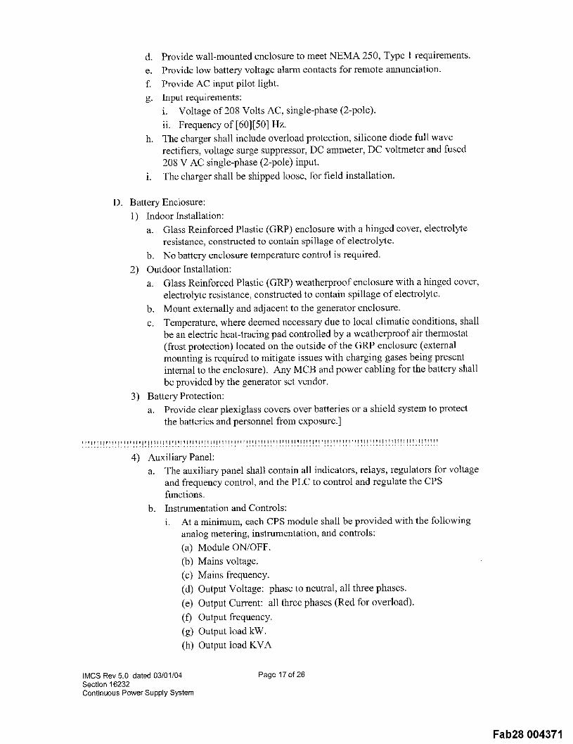
d. Provide wall-mounted enclosure to meet NEMA 250, Type I requirements.e. Provide low battery voltage alarm contacts for remote aimunciation.f. Provide AC input pilot light.g. input requirements:
i. Voltage of 208 Volts AC, single-phase (2-pole).ii. Frequency of[60][50] Hz.
h. The charger shall include overload protection, silicone diode full waverectifiers, voltage surge suppressor, DC ammeter, DC voltmeter and fused208 V AC single-phase (2-pole) input.
i. The charger shall be shipped loose, for field installation.
D. Battery Enciosttre:l) Indoor Installation:
a. Glass Reinforced Plastic (GRP) enclosure with a hinged cover, electrolyteresistance, constructed to contain spillage of electrolyte.
b. No battery enclosure temperature control is required.2) Outdoor Installation:
a. Glass Reinforced Plastic (GRP) weatherproof enclosure with a hinged cover,electrolyte resistance, constructed to contain spillage of electrolyte.
b. Mount externally and adjacent to the generator enclosure.c. Temperature, where deemed necessary due to local climatic conditions, shall
be an electric heat-tracing pad controlled by a weatherproof air them~ostat(frost protection) located on the outside of the GRP enclosurc (externalmounting is required to mitigate issues with charging gases being presentinternal to the enclosure). Any MCB and power cabling for the battery shallbe provided by the generator set vendor.
3) Battery Protection:a. Provide clear plexiglass covers over batteries or a shield system to protect
the batleries and personnel from cxposure.]
4) Auxiliary Panel:a. The auxiliary panel shall contain all indicators, relays, regulators for voltage
and frequency conlrol, and the PLC to control and regulate the CPSfi~nctions.
b. I~strumentation and Controls:i. At a minimum, each CPS module shall be provided with the following
analog metering, instrumentation, and controls:(a) Module ON/OFF.(b) Mains voltage.(c) Mains frequency.(d) Output Voltage: phase to neutral, all three phases.(e) Output Current: all three phases (Red for overload).(f) Output frequency.(g) Output load kW.(h) Output load KVA
IMCS Rev 5.0 dated 03/01104Section 16232Continuous Power Supply System
Page 17of 26
Fab28 004371
(i) Output power factor.(j) Circuit breaker position I.EDs.(k) Single CPS Only: bypass switch (normal/bypass).
(q) Indicator Lights or LED equivalent (push button):(1) Alarm: red (reset Klaxon).(2) Warning: yellow (reset alarm).(3) Operation: green (lamp test).
it. Required control relays and timers.iii. Voltage and current translbrmers as required.iv. Signaling:
(a) Choke Overtemperature: yellow.(b) Emergency stop: red.(c) ESD Gas Envelope Leak Detection: ydlow.(d) ESD Failure: red.(e) Fire shutdown: red.(f) Mains Supply Failure: yellow.(g) Not Standby: yellow.(h) Synchronous Machine Failure: red.
(i) [Battery Voltage Low: yellow.(j) Cooling Water Temperature High: red.(k) Fuel Level Low: yellow.(1) Base Tank Secondary Containment Leak Detection: red.(m)Boost charging battery: yellow.
(n) Cooling System On: green.
(o) Cooling Water Level Low: yellow.(p) Cooling water temperature low: yellow,(q) Fuel Tank Full: yellow.(r) Lube Oil Pump Failure: yellew.
IMCS Rev 5.0 dated 03/01/04Section 16232Continuous Power Supply System
Page 18 of 26
Fab28 004372
(s) Oil Pressure Low: red.(t) Overspeed: red.
(u) Reverse Reactive Load: red (parallel only).(v) Start Failure: red.]
c. FMS Interface: The FMS interface shall be provided by others and shallserve as a centralized alarm and control system tbr the facility. Provide thefollowing interface signals at each dynamic diesel auxiliary panel.i. A dry relay contact, set to activate when the control signals indicate a
Yellow Warning condition. A Ycllow Warning condition indicates teata serious condition exists, but the CPS unit is still on line and capable ofsupplying continuous power.
ii. A dry relay contact, set to activate when the control signals indicate aRed Warning condition. A Red Warning condition indicates that aserious condition exists, and the CPS unit is shut down.
iv. A dry relay contact, set to activate when system is in operation.5) Central Control Cabinet:
a. Master logic for [paralleling] [isolated redundant] modules with loadmanagement.
b. Master logic for automatic make-before-break bypass control; includeprovisions for manual operation.
c. Close bypass circuit breaker push button or switch.d. Close load circuit breaker push button or switch.e. System status.f. Main bus and bypass bus metering (kW, volt, Hz).
6) [Neutral Grounding System: CPS system shall be compatible with the upstream480V unit-substation high-resistance grounded system.]
2.8. Packaging
A. Provide all circuit breakers with the capability of accepting padlocks for safety orsecurity lockouts.
IMCS Rev 5.0 dated 03/01/04Section 16232Continuous Power Supply System
Page 19of 26
Fab28 004373
B. Provide locks on all doors to enclosures.
C. Provide floor-mounted enclosures with access all around for ease of installation andmaintenance.
D. Enclosures shall be complete with readily accessible input and output terminalconnections for all required field wiring.
E. Provide a com~ection point at each enclosure to permit attachment to the buildingground system.
F. Provide EMO but|on covers.
G. Metal enclosure surfaces shall be properly treated to remove all dirt, oxidation, and
grease prior to painting and shall be painted with higll quality scratch resistant paint.
H. Interior shect metal surfaces, used as ground or signal references for electroniccontrol circuits, shall be zinc plated.
2.9. Relay Settings
A. The CPS system Vendor shall be responsible for relay and circuit breaker settingsassociated with the CPS. The CPS system Vendor shall be responsible to coordinatethe settings with the main electrical system.
3. Execution
3.1. Installation
A. Install CPS system in accordance with manufacturer’s instructions.
kditol: )ele~e ~hc par;lglal~h-, ill brackct~ ira diesel engil’~e is n~l to be used.
B. [Fill secondary containment of skid mounted base tank with concrete, if required forfire rating, in accordance with manul’acturer’s instructions. Core drill column inconcrete for secondary containment leak detection.
C. Install analog fuel level gauge, and audible alarm horn and flashing red light for fueltank full alarm, at remote fuel fill station.]
D. Nameplates:1) When weathcrproof sound-attenuating enclosure is specil] ed, the installing
Contractor shall provide and install laminated plastic nameplates with engraved
IMCS Rev 5.0 dated 03/01/04Section 16232Continuous Power Supply System
Page 20 of 26
Fab28 004374
2)
letters per the requirements of Section 16075, Electrical Identification.Nameplates shall be provided for panelboard, transformer, enclosed circuitbreakers, and other applicable electrical equipment inside CPS enclosure.When the CPS equipment is not enclosed in a sound-attenuating enclosure, theinstalling Contractor shall provide and install laminated plastic nameplates wifl~engraved letters per the requirements of Section 16075, Electrical Identification.Provide nameplates for enclosed circuit breakers, and other applicable electricalequipment inside the CPS equipment cabinets and enclosures.
3.2. Field Quality Control
Balance of CPS System: With CPS ram~ing at full rated power after fieldinstallation, vibration levels measured at thc CPS bearing caps (or an alternatelocation specified by the A!E) sl~all not exceed 3 mils peak-to-peak at the primaryoperating speed in the vertical and two horizontal directions. Adjustments shall bemade as necessary to bring the CPS within the specified litnits. Balance reports shallbe provided for cach installed CPS.
B. Relay Settings: The CPS system Vendor shall be rcsponsible for setting and
calibrating relays and circuit breakers, complete with testing and certification.
3.3. Manufacturer’s Services
A. Provide a factory-trained field representative a| the jobsite to personally supervisethe complete installation and startup of the system; including setting, alignment,assembly, and com~ections until the system is commissioned and accepted by theOwner. Furnish the manufacturer’s written certification ensuring that each item ofequipment is complete, in good condition, free from damage, and properly installed,com~ected, and adjusted.
3.4. Startup (By CPS System Manufacturer)
A. As a minimum, include verification that the installation confomls to manufacturer’srecon~nendations.
B. Test CPS system in accordance with the requirements of Section 16080, StartupTesting And Commissioning Of Electrical Equipment.
C. Make required adjustments to the equipment, hafurm Contractor in writing of anydeficiencies.
Site Test Procedures (By CPS System Manufacturer):1) Perform a complete, no-load, functional test of the equipment to determine that
the equipment has suffered no impairment in perfor~nance since factory testswere completed.
2) Utilizing Contractor-supplied and co~mected load banks, repeat the followingtests performed at the factory:
IMCS Rev 5.0 dated 03/01/04Section 16232Continuous Power Supply System
Page 21 of 26
Fab28 004375
With each CPS module operating from power source, measure and recordthe ac following under no load, 25 percent load, 50 percent load, 75 percentload, 100 percent load, and 125 percent load for 5 minutesi. Efficiency.ii. Input voltage.iii. Input frequency.iv. Input current.v. Input power factor.vi. Output voltage.vii. Output frequency.viii.Output current.ix. Output and input kW[, including diesel starting battery charger].
b. During testing, measure and record the noise levels of each CPS modulec. For [isolated-redundant][paralleled] modules, perform the following tests
only after each module has satisfactorily completed all of the tests listedabove:i. [Demonstrate load-sharing capabilities. Record the load at each
module.]ii. Demonstrate the loss of a module; successful transfer of the load to a
redundant module; successful restart of the lost module back to the CPSsystem. Record the load at each module.
iii. Demonstrate the loss of two modules and successful transfer to bypass,successful restart [and paralleling ]of the two lost modules with the restof the system, record the load at each module, and successful retransferback to tbe CPS system.
iv. On systems paralleled for capacity, demonstrate loss of one module andsuccessfully transfer to bypass, successful restart and paralleling of thelost module with the rest of the system, and successful retransfer back tothe CPS system. Record the load at each module.
3) Measure and record the CPS efficiency with full load at unity power factor.
4) Perform communications failure check.
5) [Test CPS system to ensure ability to properly synchronize to upstreamemergency generator system. CPS system shall meet system criteria previouslyindicated in this specification while operating on line with generators.]
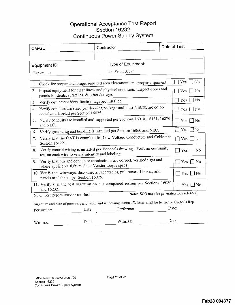
3.5. Operational Acceptance Test Repo~
A. Use the OAT form at the end of this Part to record progress and results of installationfor each unit.
IMCS Rev 5.0 dated 03/01/04Section 16232Continuous Power Supply System
Page 22 of 26
Fab28 004376
CM/GC
Equipment ID:
Operational Acceptance Test ReportSection 16232
Continuous Power Supply System
Contractor
Type of Equipment:
Date of Test
Check for proper anchorage, required area clearances, and proper alig[maent.
2. Inspect equipment for cleanliness nnd physical condition. Inspect doors andpanels for dents, scratches, & other damage.
4. Verify conduits are sized per drawing package and meet NEC®, are color-coded and labeled per Section 16075.
5. Verify conduits are installed and supported per Sections 16010, 16131, 16070and NEC.
6. Verify grounding and bonding is installed Per Secti°n 16060 and NTEC"
7. Verify that the OAT is complete for Low-Voltage Conductors and Cable perSection 16122.
8. Verify control wiring is installed per Vendor’s drawings. Perform continuitytest on each wire to verify integrity and labeling.
9. Verify that bus and conductor terminations are correct, verified tight andwhere applicable tightened per Vendor torque specs.
10. Veri@ that wireways, disconnects, receptacles, pull boxes, J boxes, andpanels are labeled per Section 16075.
ll. Verify that the test organization has completed testing per Sections 16080and 16232.
Note: Lest Reports must be attached.
[] Yes [] No
[] Yes []
[] Yes [] No
[] Yes [] No
[] Yes [] No
[] Yes [] No
[] Yes [] No
[] Yes [] No
[] Yes [] No
[] Yes [] No
[] Yes [] No
Note: SOR must be generated tbr each no "4.
Signature and date o[’persons performing and witnessing test(s) - Witness shall be by GC or Owner’s Rep.
Performer: Date: Performer: Date:
Witness: Date: Witness: Date:
IMCS Rev 5.0 dated 03/01/04Section 16232Continuous Power Supply System
Page 23 of 26
Fab28 004377
4. AppendixContinuous Power Supply (CPS) System
Section 16232Sequence Of Operations
4.1. [Description: Typical Isolated Redundant System
The Continuous Power System is configured as two Isolated Redundant Systemscomposed of five 750 kVA rotary, CPS modules, battery-free primary CPS moduleswith a sixth 750 kVA module in reserve to support any primary module that haseither:1) Failed2) Lost input power for a time approaching the available stored energy of the
primary module3) Transferred to internal bypass4) Been removed from service for preventative maintenance
B. Refer to Drawings for actual quantity of units to be installed in initial phase of work.
A PLC based CPS system controller shall be furnished. The controller must:1) Monitor the load on each primary and reserve CPS module to determine whether
more than one primary module will be allowed to transfer to the single reserveunit.
2) Be capable of assigning priorities to each primary load.
3) Logically command either the reserve module or a primary module tosynchronize its output to the other prior to performing an overlapping transferbetween modules.
4) Be capable of synchronizing the CPS system to the upstream emergencygenerator system.
Input Power (480 Volt, 3-phase, 4-wire with the neutral not bonded to ground at themodule, but referenced to the high-resistance ground at the input transformer) to theCPS system is from a substation with a main-tie-tie-main bus configuration; wherebyeach end and the middle main bus segment is fed from an independent 4160V / 480Vtransformer. Each of these transfom~ers is high-resistance grounded and is fed fromthe emergency switchgear in such a way that power to each transformer may be anyone of three utility sources or various combinations of diesel gcnerators.
E. In order to assure synchronized transfer from the reserve CPS m°dule t° a primarymodule load, the voltage of each CPS module input shall be monitored by the CPScontrol system by hard-wired sync check relays.
F. Each module shall proxdde 750kVA (750kW), 480 Volt, 3-phase, 3-wire output to adedicated critical load switchboard.
IMCS Rev 5.0 dated 03/01/64Section 16232Continuous Power Supply System
Page 24 of 26
Fab28 004378
G. Typical Sequence o f Operation:1) Normal Operation:
a. Each of (5) primary UPS modules (#2, #3, #4, #5, and #6) and the reservemodule (#1) is supplied by its assigned utility source
b. The output of each primary module powers its load via the normally-closedcircuit breaker of the MATB transfer pair, with a voltage phase-shift from itssource proportional to the amount of load.
c. The reserve module maintains output voltage to the normally open circuitbreaker of the MATB transfer pair.
2) Loss of Utility to Primary Module #2:a. Load is maintained with regulated voltage for up to 25-seconds at fall load
by the discharge of the dynamic stored energy system.b. After a time delay, the diesel engine generator system starts and rc-ei~ergizes
the input transformer. The primary module synchronizes to the generatorsystem voltage and closes the module’s input breaker. Power is rampedfrom the dynamic stored energy system to the diesel generator.
c. The CPS module is recharged to full capacity from the generator system.Should there be a block load that would otherwise cause the generatorfrequency to deviate, the CPS shall discharge to maintain frequency withinplus 0.5 I-Iz. and ramping the new load onto the generator.
3) Loss of Utility to Primary Module #2 - Diesel Fails to Start (or Input BreakerTrips):a. Load is maintained with regulated voltage for up to 25-seconds at full load
by the discharge of the dynamic stored energy system.b. Seeing no input source after a time delay, the control system commands the
primary module to synchronize to the output of the reserve module(maximum time is 3-seconds).
c. The normally-open reserve breaker closes and following a nominal 100millisecond overlap, the normally-closed primary breaker of the MATBtransfer pair opens, thus transferring load to the reserve module. Theprimary, module shuts down when its stored energy is depicted.
d. Load is maintained via the reserve module and its input source u~til inputpower is rcstored to the primary module and it is restarted and its output busenergized.
e. Return to the primary module is via a manually initiated, automatic controlsequence of the PLC controller that performs a 100 millisecond returutransfer to the primary module. Redundancy is restored to the system.
4) Loss of Utility to Primary Module #2 & #3 - Diesel Fails to Start (or InputBreakers Trip):a. See 3)a and 3)b above.b. The PLC controller monitors the load on each primary module. Should the
total load of #2 & #3 be less than or equal to the capacity of the reservemodule, both MA’fB transfer pairs operate as in 3)c thru 3)c above insequence by priority.
c. Should the load on the 2 primary modules exceed the capacity of the reservemodule, the reserve module transfer shall be to the higher priority load. If nopriority is assigned, the larger load shall be assumed to be the higher priority.
5) Maintenance Shutdown
IMCS Rev 5.0 dated 03/01/04Section 16232Continuous Power Supply System
Page 25 of 26
Fab28 004379
a. The site deeldcs on system configuration:i. Transfer the primary load to thc reserve module to maintain CPS
protection, but remove redundancy from the other loads
ii. Start the diesel generator system for the primary module to be shutdown. Transfcr the load to CPS internal bypass. Transfer the load toexternal MOTS bypass. The reserve module maintains redundancy forthe remaining primary modules.
iii. Transfer the load of the primary module to bc shut down to intcrnalbypass on utility. Transfer the load to the external MOTS bypass. Thereserve module maintains redundancy for the remaining primarymodules.]
4.2. [Description: Typical Parallel Redundant System
A. To be defined.]
End Of Section
IMCS Rev 5.0 dated 03/01/04Section 16232Continuous Power Supply System