In Section 1, we discussed the construction of the solar loop. At the solar collector, the sun’s energy is turned into heat in the form of a hot antifreeze solution. In this section we will dicuss construction of systems that will transform this energy into something that is useful to us. This usually involves the use of a heat exchanger. The FUNDAMENTALS publication has additional information about heat exchangers. In this section, we define a heat exchanger as a device that exchanges the heat within one material (or fluid) to another material (or fluid) without a mixing of the materials. In general,there are three common ways to make domestic hot water with the heated antifreeze solu- tion that the solar loop will provide. They are: 1. An external heat exchanger 2. A wrap-around type 3. An immersion type SECTION 2: END USES OF THE SOLAR ENERGY by Radiantec Company DOMESTIC HOT WATER External Heat Exchange Heat exchangers 1
Transcript
In Section 1, we discussed the construction of the solar loop. At the solar collector, the sun’s energy is turned into heat in the form of a hot antifreezesolution.
In this section we will dicuss construction of systems that will transform thisenergy into something that is useful to us. This usually involves the use of a heat exchanger.
The FUNDAMENTALS publication has additional information about heatexchangers. In this section, we define a heat exchanger as a device thatexchanges the heat within one material (or fluid) to another material (or fluid) without a mixing of the materials.
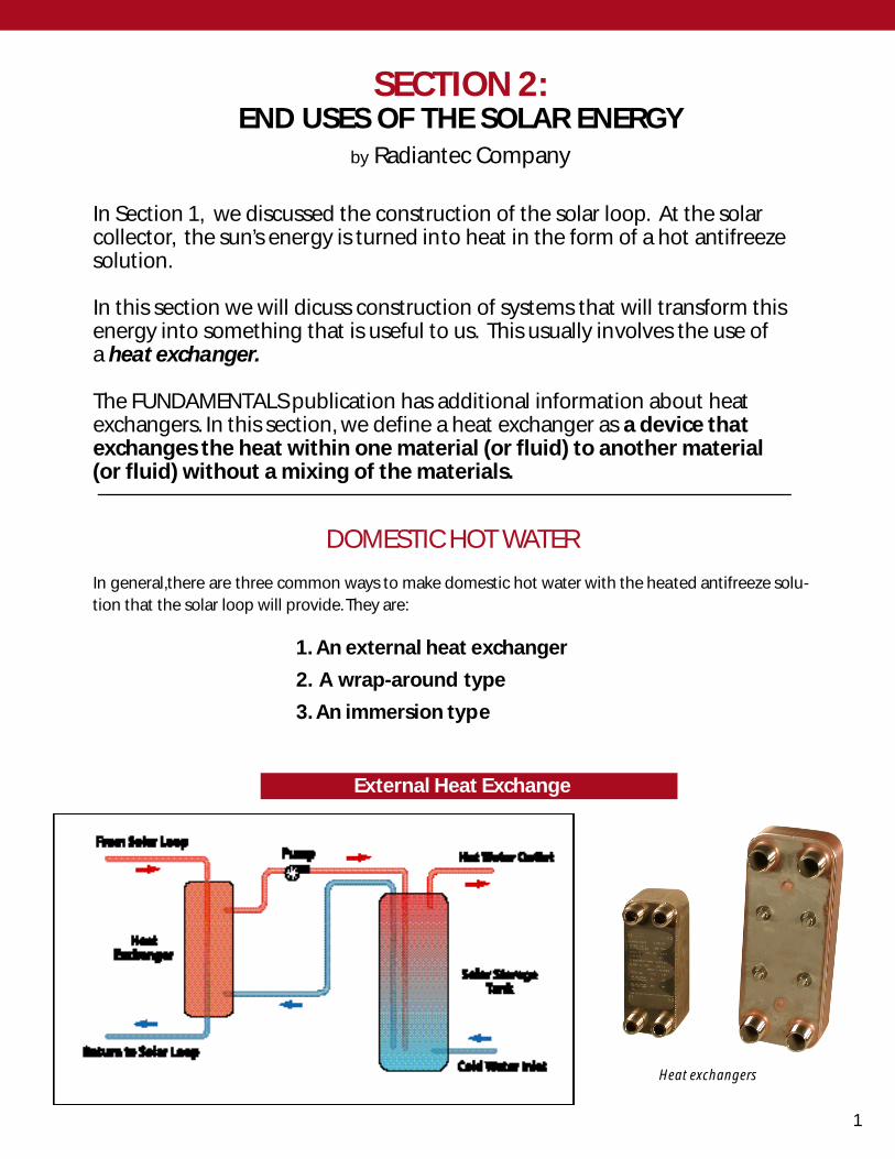
In general,there are three common ways to make domestic hot water with the heated antifreeze solu-tion that the solar loop will provide. They are:
1. An external heat exchanger
2. A wrap-around type
3. An immersion type
SECTION 2:END USES OF THE SOLAR ENERGY
by Radiantec Company
DOMESTIC HOT WATER
External Heat Exchange
Heat exchangers
1
This is a safe and efficient way to mount a stainless steel, plate-type heatexchanger.
Mount a piece of foam insulation board to the wall with glue. Make a sturdywooden frame for the heat exchanger. Screw the frame to the wall (through thefoam board) with long lag bolts. Attach the pipes to the heat exchanger andcover with another piece of foam insulation.
The domestic hot water storage tank will have two extra dip tubes. It may alsohave an auxiliary electric element.
The advantage of this approach is the separation of components. If one compo-nent fails, it does not disable the other. There is more flexibility in design.
A disadvantage is the somewhat higher cost and the complexity of a secondpump.
I t is best to use a special solar tank with ex tra dip tubes .
Do not apply excessive turning pressure to the fittings whichshould be dielectric to reduce corrosion.Instead, use the matingand machining detail decribed on page 12 of the SOLAR CON-STRUCTION MANUAL. Don’t solder directly to them.
CONTROL OF THE DOMESTIC HOT WATER PRODUCTION
Solar storage tank with extra dip tubes
Deatil of mounted heat exchanger
Connect the pump for thedomestic hot water directly tothe solar loop pump so thatthe solar controller will turnthem both on and off at thesame time.
2
USING A WRAP-AROUND HEAT EXCHANGER
The advantage of this approach is that the solar antifreeze solutionis highly unlikely to contaminate the potable domestic hot waterheater (double wall, vented separation). There is simplicity andmechanical elegance in the avoidance of the second pump.
The disadvantage is that if one component fails, it will disable theother component with it , and there will be somewhat less flexibilit yin design. At present, when you buy the tank, you get whateverheat exchanger comes with it.
Use the same precautions as above when attaching the fittings. Thehot solar fluid should come in at the top attachment to the wrap-around heat exchanger and exit at the bottom for a little extra effi-ciency.
CONTROL OF THE HEATING PROCESS— Fluid from the Solar Loopshould flow to the domestic hot water heat exchanger wheneverthe Solar Loop is operating. There is no need for a separate domes-tic hot water pump because the heat is transferred from the solarfluid to the tank directly by conduction.
The domestic hot water heater with an immersion type of heatexchanger is mechanically identical to the wrap-around type withthe exception that the heat exchanger is within the heated fluid.Extra precaution must be taken to avoid contamination of thepotable domestic hot water.
Higher efficiency and performance are possible because of immer-sion of the whole heat exchanger and often, higher storage capaci-ties are available.
The same cautions about attaching to fittings apply.
CONTROL OF THE HEATING PROCESS— Same as with the wrap-around type.
USING AN IMMERSION HEAT EXCHANGER
Wrap-around type
Immersion type
3
The solar heating system should have a good way to deal with potential overheating, particularly in thesummer when space heating is not needed. At Radiantec, we design the domestic hot water use toalways be “on”, even if everything else is “off”. This is because solar collectors should not stagnate in thesun with nothing to do. Because domestic hot water is a year around use, we design the heat dump intothe domestic hot water.
Control of overheating is achieved in several ways.
1. If the solar panels are set at an angle that directly faces the winter sun, they will be set considerablyoff the direct angle in mid-summer. This orientation will greatly lower summer performance at high tem-peratures. Some designers specify a lower efficiency heat exchanger for the domestic hot water heateron the theory that during the winter, the space heating will pick up any heat that the hot water heatermisses, and in the summer, a high efficiency heat exchanger will only cause overheating.
2. A simple shut off. Many solar controllers deal with potential overheating in this manner. Solar collec-tors must be able to withstand stagnation conditions because it can happen as a result of power failure ormechanical failure. Some medium temperature flat plate solar collectors can rise in temperature to 275° Fif they stagnate in the direct sunlight. An antifreeze solution will also raise the boiling point of the solarfluid. Certification standards specify that the solar collectors must be able to stagnate for a period of 30days without damage or loss of efficiency. Nevertheless, Radiantec does not recommend stagnation asthe primary control strategy although it can be retained as a backup.
3. Operation of the “Temperature and Pressure Relief Valve”. Every domestic hot water tank is required tohave a relief valve that will open at 200° F. But this is only intended to be a last ditch emergency device.While reassuring, this valve is not designed to operate frequently, and will start to leak eventually if it isused often. It can also dump the entire contents of the tank instead of just a little.
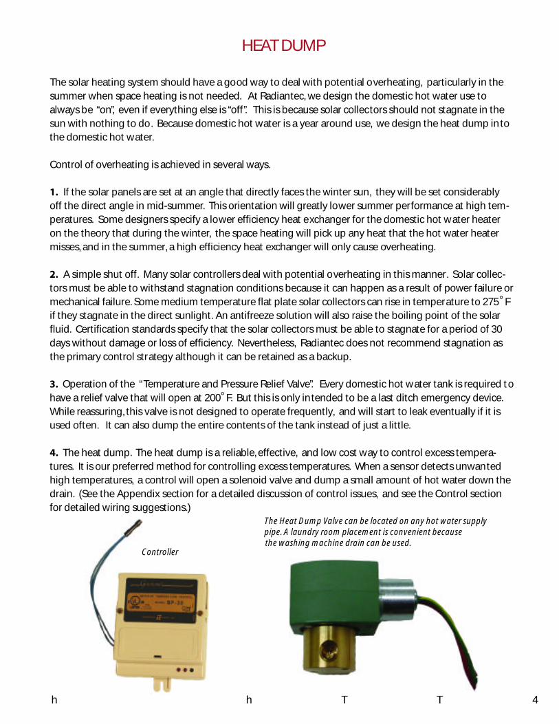
4. The heat dump. The heat dump is a reliable, effective, and low cost way to control excess tempera-tures. It is our preferred method for controlling excess temperatures. When a sensor detects unwantedhigh temperatures, a control will open a solenoid valve and dump a small amount of hot water down thedrain. (See the Appendix section for a detailed discussion of control issues, and see the Control sectionfor detailed wiring suggestions.)
The Heat Dump Valve can be located on any hot water supply
4TTh heatTthe
pipe. A laundry room placement is convenient because
HEAT DUMP
Controllerthe washing machine drain can be used.
When solar energy in combined with underfloor radiant heating, the result is high effi-ciency and excellent comfort. The solar energy harvest is efficient because of the rela-tively low operating temperature of underfloor heat.
Radiantec Company offers a DESIGN AND CONSTRUCTION MANUAL in PDF formatwhich is available at radiantec.com/next.htm. This manual will provide the detailsfor installing underfloor radiant heat.
One limitation of conventional building styles is their ability to store heat for use oncloudy days and at night when the sun did not shine.
Earlier building styles were able to store heat because of the materials that they were made of.
SPACE HEATING USING SOLAR ENERGY
Concrete installation Floor joist installation
5
The Solar Option 2 stores solar energy in both domestic hot water tanks and in the building itself.
Studies have shown that the passive heat storage detail shown above can store enough heat toenable high solar heating percentages in all areas of the continental United States
LONG TERM PASSIVE HEAT STORAGE
Figure 1
6
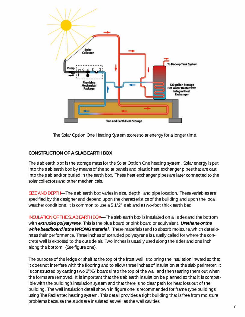
The Solar Option One Heating System stores solar energy for a longer time.
CONSTRUCTION OF A SLAB EARTH BOX
The slab earth box is the storage mass for the Solar Option One heating system. Solar energy is putinto the slab earth box by means of the solar panels and plastic heat exchanger pipes that are castinto the slab and/or buried in the earth box. These heat exchanger pipes are later connected to thesolar collectors and other mechanicals.
SIZE AND DEPTH—The slab earth box varies in size, depth, and pipe location. These variables arespecified by the designer and depend upon the characteristics of the building and upon the localweather conditions. It is common to use a 5 1/2” slab and a two-foot thick earth bed.
INSULATION OF THE SLAB EARTH BOX—The slab earth box is insulated on all sides and the bottomwith extruded polystyrene. This is the blue board or pink board or equivalent. Urethane or thewhite beadboard is the WRONG material. These materials tend to absorb moisture, which deterio-rates their performance. Three inches of extruded polystyrene is usually called for where the con-crete wall is exposed to the outside air. Two inches is usually used along the sides and one inchalong the bottom. (See figure one).
The purpose of the ledge or shelf at the top of the frost wall is to bring the insulation inward so thatit does not interfere with the flooring and to allow three inches of insulation at the slab perimeter. Itis constructed by casting two 2”X6” boards into the top of the wall and then tearing them out whenthe forms are removed. It is important that the slab earth insulation be planned so that it is compat-ible with the building’s insulation system and that there is no clear path for heat loss out of thebuilding. The wall insulation detail shown in figure one is recommended for frame type buildingsusing The Radiantec heating system. This detail provides a tight building that is free from moistureproblems because the studs are insulated as well as the wall cavities.
7
FILLING THE EARTH BOX—The earth box is filled with clean fill that contains no topsoil or organicmatter that might cause the slab to settle. Clean sand or gravel is ideal. The following is a list of“Non-problem” soils.
SOIL TYPE SOIL DESCRIPTIONGW,GP Gravels or sandy gravels :little or no finesGM,GC Gravels or sandy gravels with sand or siltSW, SP Sand with little or no finesML Fine sand with silt or clayMH Inorganic clay or silt
CAUTION: Do not spend extra money on stone. It will not store more heat. Do not use fill withsharp stones as they could damage the pipes. Do not use crushed rock or cinders in the vicinity ofthe pipes.
COMPACTION—The earth box is heavily compacted during the fill. Good compaction is importantwith any slab to prevent settling and cracking from differential settling of the fill. Compaction isperformed with a mechanical compactor on 6” lifts (layers) of soil. Compaction continues untilthe soil feels very solid (90-95% of optimum dry density).
PLACEMENT OF THE MANIFOLD BOX—The manifold box is the place where the plastic pipe com-ing from the slab earth box connects to the copper pipe in the rest of the system. The manifoldbox should contain equipment for air testing the slab earth heat exchanger to ensure there are noleaks in the pipe. The solar fluid will come down from the solar panels by way of a copper pipe andthen branch off into several plastic tubing heat exchanger pipes. The solar fluid is cooled by theslab and then returns to the solar collectors.
8
The manifold box as supplied by Radiantec Company contains the manifold, pressure gauge, airstem, air vent and a valve. It has been pre tested at the factory. This equipment comes in a sturdyplywood box that protects the components from shipping damage, and is also used for protectionduring the remainder of the building construction.
Partly disassemble the manifold box by removing the top, the bottom and the upper half of thesides. This will permit access to the manifold for connection to the plastic heat exchanger tubing.
Locate and level the box in the place called for in the plans. If tubing is to be placed within the earthbox as well as in the slab, it will be necessary to set the manifold box upon stilts in order to level it inthe proper location. An easy way to do this is with large C clamps and four short pieces of 2”X4”boards. It is important to note that the manifold box must be secured well. If the manifold boxbecomes crooked during the earth filling, it may not be practical to straighten it later. It will lookunsightly and spoil the overall professional appearance of the work.
The manifold box is now ready to be connected to the polyethylene heat exchanger tubing.Designate one side to be the supply and the other to be the return.
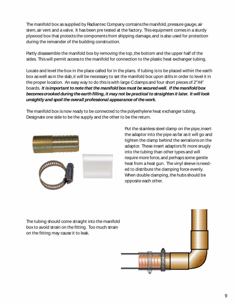
Put the stainless steel clamp on the pipe, insertthe adaptor into the pipe as far as it will go andtighten the clamp behind the serrations on theadaptor. These insert adaptors fit more snuglyinto the tubing than other types and willrequire more force, and perhaps some gentleheat from a heat gun. The vinyl sleeve is need-ed to distribute the clamping force evenly.When double clamping, the hubs should beopposite each other.
The tubing should come straight into the manifoldbox to avoid strain on the fitting. Too much strainon the fitting may cause it to leak.
9
PLACEMENT OF THE PIPE
Tighten the nut ontothe threaded fittingwith the compressionring in between.There is no need totighten the fittingexcessively.
1/2” P EX TUBING WITH A COMPRESSION FITTING TO 3/4”TUBING
10
PLACEMENT OF THE PIPE
1. Use only the pipe specified for the job. Check the pipe carefully for shipping damage. The pipeshould come to the job site in a shipping car ton to help spot damage. Inspect the pipe continuouslywhen working with it. We recommend that you order an extra coil of tubing and either use it la ter orsend it back. Radiantec will not charge a restocking fee.
2. Considerations in pipe selection include temperature and pressure resistances, solubility withantifreeze solutions, durability over time, appropriate flow characteristics, proper rate of heat transferand other important factors. Do not substitute tubing without considering what the change willmean. A slab heat exchanger constructed from the proper material will outlast the building in which itis installed.
3. Pipes may be concentrated somewhat in areas such as bathr ooms where more heat and air circula-tion is wanted.
4. Do not go over the pipe with wheelbarrows. Do not drop heavy equipment on the pipes or oth -erwise abuse them. Pipes will withstand the ordinary conditions of a concrete pour. Make sure thateach person doing the earth filling or concrete work kno ws this.
5. During earth fill, pipes may be held in place with construction boards or with wire mesh.
6. It is not unusual to have to discard a small amount of tubing in order to get go od arrangement. Itwill not make much difference
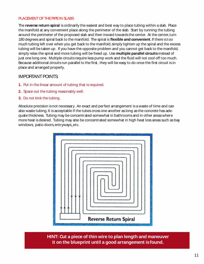
PLACEMENT OF THE PIPE IN SLABS
The reverse return spiral is ordinarily the easiest and best way to place tubing within a slab. Placethe manifold at any convenient place along the perimeter of the slab. Start by running the tubingaround the perimeter of the proposed slab and then inward towards the center. At the center, turn180 degrees and spiral back to the manifold. The spiral is flexible and convenient. If there is toomuch tubing left over when you get back to the manifold, simply tighten up the spiral and the excesstubing will be taken up. If you have the opposite problem and you cannot get back to the manifold,simply relax the spiral and more tubing will be freed up. Use multiple parallel circuits instead ofjust one long one. Multiple circuits require less pump work and the fluid will not cool off too much.Because additional circuits run parallel to the first, they will be easy to do once the first circuit is inplace and arranged properly.
IMPORTANT POINTS:
1. Put in the linear amount of tubing that is required.
2. Space out the tubing reasonably well.
3. Do not kink the tubing.
Absolute precision is not necessary. An exact and perfect arrangement is a waste of time and canalso waste tubing. It is acceptable if the tubes cross one another as long as the concrete has ade-quate thickness. Tubing may be concentrated somewhat in bathrooms and in other areas wheremore heat is desired. Tubing may also be concentrated somewhat in high heat loss areas such as baywindows, patio doors, entryways,,etc.
HINT: Cut a piece of thin wire to plan length and maneuverit on the blueprint until a good arrangement is found.
11
THE PRESSURE TEST—Before burying pipe, pressure test the assembly with 50 psi of air for at least4 hours, and preferably overnight. Use a soap suds solution and check for bubbles. Any leaks aremost likely right at the manifold. There should be no loss of pressure. Schedule the work so youare not rushed at this time. Maintain working pressure (20 psi) while the pipe is being buried orcast into the concrete. If tubes are to be installed within the earth bed as well as within the slab, itwill be necessary to pressure test the earth loops before the slab loops are in place. The use oftwo separate manifolds is the easiest way to do this.
CONCRETE RECOMMENDATIONS—(these are general recommendations and what Radiantec con-siders good practice. However, Radiantec does not accept responsibility for the design of any par-ticular project.)
1. Foundation walls with footings should be provided to bear the weight of the building.Carryover slabs, thickened edge slabs, etc. are often structurally inadequate and cannot be insu-lated well. When used, they must be professionally designed.
2. Slabs should not bear on the foundation walls but should bear upon the compacted fill.
3. Floor slabs should be 5” thick,minimum. No length or width of the slab should exceed 75 feetwithout an isolation joint. Control joints should be placed every 15 to 20 feet. Odd shapes shouldbe divided into rectangles with control joints or isolation joint.
4. The concrete mix for a floor slab should be a 6 bag mix with 3,500 psi compressive strength. Itshould contain 6 gallons of water per sack and should have a slump of 2-4”. This mixture will bequite stiff and not as easy to work with as a soupy mixture. It is however, a lot stronger and moreresistant to cracking. A vibrator is handy when placing stiff concrete. Water may be added ifabsolutely necessary.
5. Use a moist cure method of curing the concrete. The work should be kept moist with coveringsfor at least 3 days after the pour. No load should be placed on the slab during this time. It is neverbeneficial to cause a slab to dry out quickly.
Very heavy objects such as fireplaces, chimneys, etc. should be footed separately from the slab andpipes. Hot water heaters should have their own pad that is isolated from the slab. Places that willbear interior partitions should be made stronger with extra concrete and more steel. The mani-fold box should be reconstructed with the boards that were removed in order to protect the man-ifold from accidents during the remainder of the building construction.
12
An advantage of the snow melting application is that it can use low-grade sunshinethat is not useful for anything else because of its very low operating temperature.
A supplemental boiler is often used if all weather operation is needed. For efficiency,the boiler is used in conjunction with strong sunlight in order to get the job over withquickly, so the heat can be turned off.
Use 1/2” PEX for high strength and durability. Its thicker walls and lower efficiency areless important because of the large temperature difference between the heating fluidand the ground. Typical spacing is 12” on center. Scraps of wire mesh, left over fromconcrete work, can be used for tying and managing the tubing.
The tubing should be placed in the earth about 6”- 8” beneath the surface.
Pressurize the tubing when work is being done above it.
Run cold water through the tubing if asphalt is being placed.
In general,do not insulate under the snowmelt area. The ground beneath is usuallywarmer than 32° F.
SNOW MELT
13
Studies in greenhouses show that root zone heating can be highly effective. Root zone heat-ing can extend the season on both ends. It can make it possible to grow plants that would nototherwise grow in your zone.
GARDENS
SOLAR ENERGY CAN BE FUN. A HIGH PERFORMING SOLAR HEATINGSYSTEM WILL MAKE MORE HEAT THAN YOU REALLY NEED FOR HEATING
AND DOMESTIC HOT WATER AT CERTAIN TIMES.
YOU CAN USE THE EXCESS HEAT IN FUN AND IMAGINATIVE WAYS THATYOU MIGHT NOT CONSIDER IF YOU HAD TO USE FOSSIL FUELS
GO AHEAD, IT’S FREE!
14
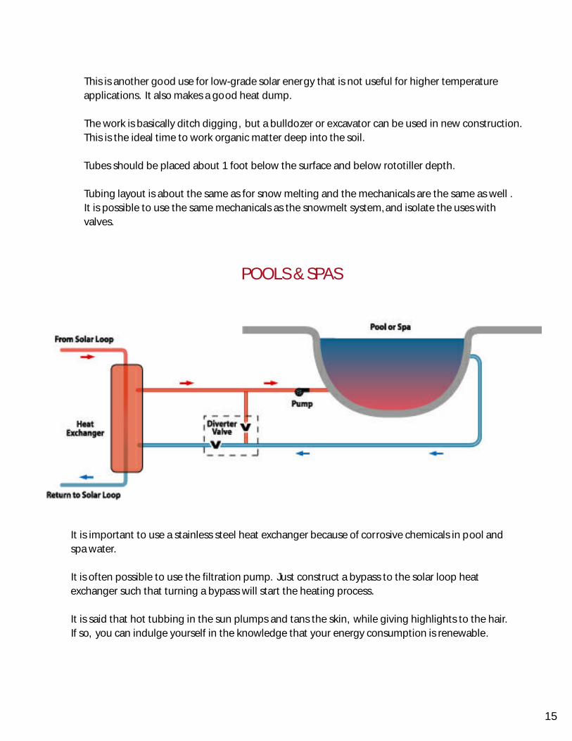
It is important to use a stainless steel heat exchanger because of corrosive chemicals in pool andspa water.
It is often possible to use the filtration pump. Just construct a bypass to the solar loop heatexchanger such that turning a bypass will start the heating process.
It is said that hot tubbing in the sun plumps and tans the skin, while giving highlights to the hair.If so, you can indulge yourself in the knowledge that your energy consumption is renewable.
This is another good use for low-grade solar energy that is not useful for higher temperatureapplications. It also makes a good heat dump.
The work is basically ditch digging, but a bulldozer or excavator can be used in new construction.This is the ideal time to work organic matter deep into the soil.
Tubes should be placed about 1 foot below the surface and below rototiller depth.
Tubing layout is about the same as for snow melting and the mechanicals are the same as well .It is possible to use the same mechanicals as the snowmelt system, and isolate the uses withvalves.