83
| Date post: | 11-Jul-2018 |
| Category: |
Documents |
| Upload: | truongphuc |
| View: | 214 times |
| Download: | 0 times |


Locomotive Control StationFig. 2-1
SECTION 2
CAB CONTROLS
INTRODUCTION
All of the control equipment used during locomotiveoperation is located in four separate areaswithin the cab .These are the (1) control panel, (2) the engine controlpanel, (3) the locomotive controller and (4) the air brakepedestal . Each of these areas contains various devicesthe engineman should be familiar with as most of themwill be used at one time or another during operation.
The first two areas are panels on which aremounted switches and circuit breakers that must beproperly positioned to establish electrical circuits foroperation. Once set, these devices need no furtherattention since actual operation of the locomotive is thencontrolled from the control station shown in Fig. 2-1 .This location contains the locomotive controller and airbrake pedestal which are the remaining control areas.
Each of the control areas and the equipment theycontain are fully described in the following articles .The paragraph number corresponds with the numbersgiven on the illustrations.
CONTROL PANEL,Fig. 2-2
The control panel switches, shown in Fig. 2-2, arelocated within the electrical cabinet which forms therear wall of the locomotive cab . Their position is in theupper left hand corner .
Upon opening the cabinet door,the following items will be observed .
1 . AUXILIARY GENERATOR VOLTAGEREGULATOR
The locomotive low voltage system and equip-ment are designed for operation on 74 volt DCpower supplied by the auxiliary generator. This

CAB CONTRO LS
1 . Voltage Regulator
8. Auxiliary Generator Field2. Control Circuit Breaker
Fuse3 . Local Control Circuit
9. Fuse Test EquipmentBreaker
10. Battery Field Fuse4. Lights Circuit Breaker
11. External Battery Charging5. External Battery Charging
FuseReceptacle
12. Auxiliary Generator Fuse6. Alternator Field Fuse
13. Starting Fuse7. Ground Relay Knife Switch
14. Main Battery Knife Switch
Control PanelFig. 2-2
CAB CONTROLS
voltage must be kept constant regardless ofchanges in engine (and generator) speed.
The voltage regulator is used in the auxiliarygenerator field excitation circuit and functions tovary excitation as needed to hold output voltageconstant despite speed changes . This devicefunctions entirely automatically and should neverbe disturbed in operation .
2. CONTROL 30-AMPERE CIRCUIT BREAKER
This circuit breaker must be in the ON positionin order for the locomotive to be operated . Itestablishes power from the battery for operatingthe fuel pump and starting the engine . Oncethe engine is running, power is supplied throughthe control circuit breaker from the auxiliarygenerator to maintain operating control.
3 . LOCAL CONTROL 30-AMPERE CIRCUITBREAKER
This circuit breaker must be in the ON positionin order for the locomotive to be operated, Itestablishes "local" power from the auxiliarygenerator to operate certain of the heavy-dutyelectro-magnetic switchgear components con-tained in that particular unit.
This switch is necessary since the circuitsenergizing such equipment could not be train-lined in a multiple unit consist due to the ex-cessive power requirements from the lead unitauxiliary generator. Thus the lead unit simplyestablishes control or pilot circuits in trailingunits which in turn bring in the actual equip-ment components using local control power .
4 . LIGHTS - 30-AMPERE CIRCUIT BREAKER
This circuit breaker must be ON to supplypower for the individual switches provided forplatform, engineroom and identification lights .

CAB CONTROLS
5. BATTERY CHARGING RECEPTACLE
Whenever it is considered necessary, the loco-motive storage battery may be charged froman external source through means of the charg-ing receptacle provided . A fuse, discussed inItem 11, is provided to protect the chargingcircuit .
6 . ALTERNATOR FIELD 60-AMPERE FUSE
The alternator receives its excitation through apair of slip rings connected to the low voltageDC auxiliary generator output . To protect thesewindings, a 60-ampere fuse is provided in theexcitation circuit . This fuse must be good andin place at all times during locomotive operation.
In the event that the fuse is blown, alternatorexcitation and resulting AC power output willcease. This causes the no AC voltage relay(NVR) to function setting off the no power alarmsand reducing engine to idle, or stop dependingon throttle setting in the unit affected.
7 . GROUND RELAY KNIFE SWITCH
The purpose of the ground relay knife switchis to eliminate the ground protective relay fromthe locomotive circuits during certain shopmaintenance inspections . It MUST ALWAYSBE KEPT CLOSED in normal operation other-wise the protection offered by the ground relaywould be nullified and possible serious equip-ment damage could occur . It may be openedhowever in the event of extreme emergencyupon receipt of definite instruction to that effectfrom a responsible officer of the railroad .
CAB CONTROLS
8 . AUXILIARY GENERATOR FIELD30-AMPERE FUSE
The field excitation circuit of the auxiliarygenerator is protected by a 30-ampere fuse .This fuse must be good and in place at alltimes during locomotive operation .
In the event that this fuse is burned out, itopens the generator excitation circuit whichstops generator output to the low voltage sys-tem. An alternator failure (no power) alarmwould then occur due to the functioning of theno AC voltage relay (NVR) since the auxiliarygenerator could no longer provide excitationcurrent for the alternator. The NVR also opensthe circuit to the ER relay which causes theengine speed inthe unit affected tobe reduced toidle, or stop if in the 5th or 6th throttle position .
9 . FUSE TEST EQUIPMENT
To facilitate the testing of fuses, a pair of fusetest blocks, a test light and a test light toggleswitch are installed on the control panel.
Fuses may be readily tested as follows .
First,move the toggle switch ON to make sure thefuse test light is not burned out .
Extinguish thelight by moving the toggle switch OFF. Placea fuse across the test blocks so that the metalends of the fuse are in firm contact with theblocks .
If the fuse is good, the light will comeon.
If the fuse is burned out, the light will notcome on and a new fuse is required .
It is advisable to always test fuses before in-stalling them in their circuits . Always isolatethe circuits in question by opening their switchesbefore changing or replacing fuses.

CAB CONTROLS
10. BATTERY FIELD 80-AMPERE FUSE
The battery field windings of the main genera-tor are excited with current received from thelocomotive low voltage system. This circuit isestablished by means of the battery field (BF)contactor .
The 80-ampere battery field fuse isused in this circuit for protection against pos-sible overload or short circuit damage .
The fuse must be in good condition, since if itis blown, the locomotive unit concerned will notdevelop normal power due to lack of main gen-erator excitation . In such instances, no alarmswould occur but the trouble would be recognizeddue to loss of locomotive power.
11. EXTERNAL BATTERY CHARGING100-AMPERE FUSE
In the event that the locomotive storage batteryis to be charged from an external source, aplug receptacle, Item 5, Fig. 2-2, is provided .The 100-ampere charging fuse is in the circuitbetween the receptacle and battery to preventcharging current in excess of equipment andwiring capacity .
This fuse is required only during instances ofexternal battery charging. It does not affectlocomotive operation in any way.
12 . AUXILIARY GENERATOR 150-AMPERE FUSE
During locomotive operation, the auxiliary gen-erator supplies all of the locomotive low voltagerequirements . This generator is rated at 10kilowatt capacity . To prevent overloading andpossible damage due to excessive current de-mands, a 150-ampere fuse is installed in thecircuit connecting the generator to the lowvoltage system.
- 205 -
NOTE :
CAB CONTROLS
On units equipped with a steam generator, ahigher capacity 18 KW auxiliary generator isused in place of the basic 10 KW machine . Thefuse used in such instances has a capacity of 250amperes. Care should be taken to make surethat this larger capacity fuse is never installedon units equipped with the smaller generator .
The auxiliary generator fuse must be installedand in good condition at all times during loco-motive operation. In the event that the fuseblows out, the circuit for alternator excitationwill be open with the result the AC currentoutput will cease . This causes the no AC volt-age relay (NVR) to drop out which de-energizesthe ER relay and brings the engine to idle, orstop if in the 5th or 6th throttle position . The nopower alarm would also occur and be indicatedon the unit affected .
13 . STARTING 400-AMPERE FUSE
The starting fuse is in use only during theperiod that the diesel engine is actually beingstarted. At this time, battery current flowsthrough the fuse and starting contactor to mo-torize the main generator and crank the engine .
Although this fuse should be in good conditionand always left in place, it has no affect onlocomotive operation other than for engine start-ing . A defective fuse can be determined whenattempting to start the engine since at that time,even though the starting contactor closes, thecircuit is open preventing the generator fromcranking the engine .
14 . MAIN BATTERY KNIFE SWITCH
The large double pole, single throw knife switchat the lower right hand corner of the control
- 206 -

panel is the main battery switch and is usedto connect the battery to the locomotive lowvoltage system. It should be kept closed at alltimes during operation.
If this switch were left open, the fuel pumpcould not be started, the lights would not func-tion and the engine could not be started. If theswitch were opened after the engine was startedand the auxiliary generator was supplying thelow voltage needs, then the batteries could notbe charged.
This switch may be opened during certain shopmaintenance procedures and in instances wherethe engine is shut down and the locomotive takenout of service for an extended layover . Thiswill prevent the battery from being dischargedin the event the lights or other low voltage de-vices are inadvertently left operating during thelayover.
ENGINE CONTROL PANEL, Fig. 2-3
The engine control panel, Fig . 2-3, is mounted inthe rear wall of the cab above the electrical cabinet .This panel contains several switches, circuit breakersand alarm lights, along with engine start, stop andground relay buttons and a battery charging ammeter.Since all of these items will be used at one time oranother during operation, a brief description of theirindividual functions follows :
1 . LIGHT SWITCHES
CAB CONTROLS
Individual switches are provided for platformand engineroom lights . In order for theseswitches to be functional, the 30-ampere "lights"circuit breaker (located on the control panel)must be ON.
CAB CONTROL-S
c. ~ U0 3
~cli M
c. m
c0 0UCd
x
o ~ s. a~ 3a~mx~ a,Co ai
O
O1-4 c.
a .~
oa
by.2o=- U .y 60 .G
Wco~aa
cdad$ w
Uo 0wwxz
0
0CCd
CqU ~
'-+ 4
M 0 $. 0a"w ,~ 0x14 N
M
M
CAB CONTROLS
2. BATTERY CHARGING METER
With the main battery knife switch closed, thebattery charging meter is connected into thelow voltage circuit to indicate whether currentis flowing to or from the storage battery . Thismeter does not indicate the output current ofthe auxiliary generator . Since the storagebattery is usually well charged, the meter innormal operation should read zero or a slightcharge .
When the engine and auxiliary generator arestopped, all low voltage current requirementssuch as for lights, fuel pump motor and cabheaters are supplied by the storage battery . Insuch instances, current would be coming fromthe battery which would be discharging, andthe meter pointer would be reading to the leftof the center-zero position.
When the diesel engine is started, the auxiliarygenerator is in operation and will be supplyingall low voltage current needs . In addition, thegenerator will also be charging the storagebattery . In such instances, current will beflowing to the storage battery and would be in-dicated by the meter pointer being to the rightof center-zero or charge side of the meter.
During normal operation, the meter shouldalways be indicating either zero or a slightcharge . A zero indication would mean that thebattery was fully charged . The meter shouldnever indicate discharge with the diesel enginerunning, even at idle speed. Such a readingwould indicate that the battery was discharging,which if allowed to continue, could possiblylead to ultimate failure of the locomotive unit.
NOTE
CAB CONTROLS
3. GROUND RELAY RESET PUSH BUTTON
The ground relay can detect a low voltage groundwhen starting the engine or a high voltage groundduring operation under power. In either in-stance, it would trip to set off the alarm andilluminate the ground relay light on the con-troller . In addition, the diesel engine speedcould not be advanced above IDLE in the unitaffected .
To reset the ground relay and restore locomo-tive power, it is first necessary to isolate theunit affected or place the throttle in idle . Theground relay reset button may then be depressedto reset the relay and restore the locomotivecircuits for normal operation .
The button should not be held in as this will notkeep relay from tripping . Repeated tripping ofthe ground relay under power is cause for isolation of the unit concerned .
In instances wheretripping is accompanied by wheel slip light in-dications, the locomotive should be stopped andall wheels inspected to make sure that none aresliding .
4 . ENGINE START PUSH BUTTON
In order to start the diesel engine, the fuelpump must be running, the isolation switchmust be in the START position and then theSTART push button may be depressed . Doingso establishes circuits to close the startingcontactor (GS) which allows battery current toflow through the armature and starting fieldwindings of the main generator . This motor-izes the generator to crank the engine.
In starting the engine, the push button shouldbe depressed firmly and held in until the enginestarts (no more than 15 seconds) .
If the engine

CAB CONTROLS
does not start, refer to the trouble shootingsection of this manual for likely causes .
5 . ENGINE STOP PUSH BUTTON
To stop the diesel engine, the isolation switchmust first be placed in the START positionafter which the engine STOP push button maybe depressed. Doing so energizes the "D" orshutdown solenoid in the engine governor . Thegovernor then functions to move all of the injec-tor racks to the no fuel position which causesthe diesel engine to stop.
When stopping the engine, the button must bedepressed firmly and held IN until the engineis completely stopped. Releasing it prematurelywill allow the engine to regain fuel and returnto idle speed.
6 . HOT ENGINE ALARM LIGHT
The hot engine alarm light (red) operates inconjunction with the alarm bell to warn theengineman that the engine cooling water hasreached an excessive temperature . This alarmlight will be illuminated only in the unit affectedalthough the alarm bell will ring on all unitsin the locomotive consist .
The hot engine alarm will not affect locomotivespeed or power. It simply serves as a warning.The alarm will not cease functioning untilengine temperature is reduced to a normalvalue . The bell cannot be silenced by isolatingthe unit as is true with other types of alarms.
Refer to the trouble shooting section for causesand correction of a hot engine.
CAB CONTROLS
7 . NO POWER ALARM LIGHT
The green no power light will come on and thealarm bell will ring any time the no AC voltagerelay (NVR) is open with the isolation switch inRUN position . This would occur if the enginestopped for any reason or an alternator failureoccurred during operation .
When this alarm occurs, the engine willbe eitherrunning at idle or stopped. If it occurred withthe engine running, it indicates a true alternatorfailure or electrical difficulty . If, on the otherhand it occurs when the engine stops, the causeof such stopping may be the cause of the alarm.
Refer to the trouble shooting section for possi-ble cause and the corrective action to be taken.
8 . LOW OIL ALARM LIGHT
Built into the diesel engine governor is a mech-anism to detect low engine lubricating oil pres-sure or high suction . In either event, a smallbutton will pop out of the governor to stop thediesel engine and activate the alarms throughmovement of a switch.
The yellow low oil alarm light will come onand the alarm bell will ring through circuitsestablished by this tripped switch. Isolatingthe unit or resetting the governor button willextinguish the alarm light and silence the bell.Refer to the trouble shooting section for detailsof causes and corrections .
9. MISCELLANEOUS CIRCUIT BREAKERS
Provision is made for the installation of sev-eral circuit breakers in the lower left handportion of the engine control panel. These

A. On Lead Units
CAB CONTROLS
can include one each for the water cooler,automatic train control (if used), the headlight,road lights, and cab heater. The headlightcircuit breaker is rated at 30-amperes whilethe others have 15-ampere capacities. Thesecircuit breakers should be turned ON to obtainoperation of desired features .
10 . HEADLIGHT CONTROL SWITCH
The twin sealed-beam front and rear headlightsare controlled by the front and rear headlightswitches on the locomotive control panel. Adimming switch is mounted on the right sideof the controller. Before these switches willfunction, the 30-ampere headlight circuit breakeron the engine control panel must be placed ON.
On locomotives equipped for multiple unit op-eration, a remote headlight control switch ismounted on the engine control panel. This re-mote headlight control switch permits operationof the headlight of the rear unit to be controlledfrom the lead unit .The switch isshown in Fig. 2-4and its positionsare set on eachunit as follows :
If only a singlelocomotive unitis being used,place the switchin the "SINGLE
Remote Headlight SwitchUNIT"position .
Fig. 2-4
In multiple unit service, if trailing units arecoupled to the No. 2 or long hood end of thelead unit then place the switch in the "CON-TROLLING - coupled at No. 2 end position."
CONTROLLING CONTROLLINGWITH UNIT COUPLED WITH UNIT COUPLEDAT NO. 2 END
AT NO . I END
HEADLIGHT CONTROL
NOTE
CAB CONTROLS
In multiple unit service, if trailing unitsare coupled to the No . 1 or short hood endof the lead unit, place switch in "CONTROL-LING - coupled at No. 1 end position."
B. On Intermediate Units
On units operating in between other unitsin a multiple unit consist, place the switchin the "SINGLE UNIT" position .
C . On Trailing Units
The last unit in a multiple unit consistshould have the headlight control switchplaced in the "CONTROLLED" from otherunit position .
11 . UNIT SELECTOR SWITCH
The unit selector switch is used only on loco-motives equipped with dynamic brakes . Itspurpose is to adjust circuit resistance for uni-form dynamic brake operation regardless of thenumber of units in the locomotive consist .This switch should be set to the No. 1, 2, 3 or4 position depending on the number of locomo-tive units physically and electrically connectedtogether . The switch position should not bechanged for any reason other than to correspondto a change in number of units being operated .For example, it should not be changed if one ofthe units is isolated or shut down yet remainsin the locomotive consist.
This switch position is of importance only inthe lead or controlling locomotive unit duringoperation in dynamic braking . It has no functionon intermediate or trailing units .
Switch position may be changed only while thethrottle is in IDLE or locomotive is at rest.

CAB CONTROLS
It should never be moved while operating indynamic braking .
12 . ISOLATION SWITCH
The isolation switch has two positions, START(or isolate) and RUN. The functions of thesetwopositions, shown in Fig. 2-5, are as follows :
A. Start Position
The isolation switch is placed in this posi-tion whenever the diesel engine is to bestarted or stopped. The START and STOPpush buttons are effective only in this switchposition .
The START position is also used to isolatethe unit which will prevent it from develop-ing power and responding to controls . Insuch instances, the engine will be runningat idle speed regardless of throttle position .This position will also silence the alarmbell in the event of a no power or low lubeoil alarm. It will not, however, stop thealarm in the event of a hot engine.
Isolation Switch PositionsFig. 2-5
B. Run Position
CAB CONTROLS
After the engine has been started, the unitmay be placed "on the line" by moving theisolation switch to the RUN position . Theunit will then respond to control and willdevelop power in normal operation .
NOTE : The isolation switch should never be movedfrom one position to another while operating indynamic braking . Dynamic braking should betemporarily terminated (by placing throttle inidle) whenever it is desired to place the unit onor off the line . It is also good practice whileoperatingunder power to first return the throttleto idle before changing isolation switch position.
13 . FUEL PUMP CIRCUIT BREAKER
Located at the lower right hand corner of theengine control panel is another group of circuitbreakers. They include double-pole 30-amperecircuit breakers for the RADIO, HOPPERHEATER (if used) and a single-pole 15-ampereFUEL PUMP circuit breaker . The fuel pumpcircuit breaker must be ON for normal oper-ation. The others may be placed on to meetoperating requirements .
The fuel pump circuit breaker must be ON inall units of the locomotive consist in order forthe individual fuel pumps to operate . The othercircuit breakers may be placed off on all trail-ing units without affecting operation .
LOCOMOTIVE CONTROLLER, Fig. 2-6
The locomotive controller is shown in Fig . 2-6.It contains the necessary switches, gauges and operatinglevers that are used by the engineman during operationof the locomotive. The individual components of the

CAB CONTROLS
Locomotive ControllerFig. 2-6
B . Run Position
CAB CONTROLS
After the engine has been started, the unitmaybe placed "on the line" by moving theisolation switch to the RUN position . Theunit will then respond to control and willdevelop power in normal operation.
NOTE : The isolation switch should never be movedfrom one position to another while operating indynamic braking. Dynamic braking should betemporarily terminated (by placing throttle inidle) whenever it is desired to place the unit onor off the line. It is also good practice whileoperatingunder power to first return the throttleto idle before changing isolation switch position .
13 . FUEL PUMP CIRCUIT BREAKER
Located at the lower right hand corner of theengine control panel is another group of circuitbreakers . They include double-pole 30-amperecircuit breakers for the RADIO, HOPPERHEATER (if used) and a single-pole 15-ampereFUEL PUMP circuit breaker. The fuel pumpcircuit breaker must be ON for normal oper-ation. The others may be placed on to meetoperating requirements .
The fuel pump circuit breaker must be ON inall units of the locomotive consist in order forthe individual fuel pumps to operate . The othercircuit breakers may be placed off on all trail-ing units without affecting operation.
LOCOMOTIVE CONTROLLER, Fig. 2-6
The locomotive controller is shown in Fig. 2-6 .It contains the necessary switches, gauges and operatinglevers that are used by the engineman during operationof the locomotive . The individual components of the
1 . Load Indicating 3 . Indicating Lights 6 . Throttle LeverMeter 4 . Operating Switches 7 . Reverse Lever
2 . Air Gauges 5 . Headlight Dimming 8 . Selector LeverSwitch

CAB CONTROLS
1 . Load Indicating
3. Indicating Lights
6 . Throttle LeverMeter
4. Operating Switches 7 . Reverse Lever2 . Air Gauges
5. Headlight Dimming 8 . Selector LeverSwitch
Locomotive ControllerFig. 2-6
CAB CONTROLS
controller are described, together with their functions,in the following paragraphs.
1 . LOAD INDICATING METER
The locomotive pulling force is indicated bythe load indicating meter located at the upperportion of the controller . This meter is grad-uated to read amperes of electrical currentwith 1500 being the maximum reading on thescale .
The meter is connected so as to indicate thecurrent flowing through the No . 2 traction motor.Since the amperage is the same in all motors,each motor will be receiving the amount shownon the meter.
Since the traction motors receive their powerfrom the main generator, the meter readingsmay be multiplied to determine the approximategenerator current output . The multiplying fac-tor will depend, however, on the particulartransition circuit in effect at the time the read-ing is taken. For example, when operating intransition 1, the multiplying factor is 2 andin transition 2, 3 and 4 it is 3 .
Thus a meter reading of 200 amperes wouldindicate a generator output of 400 ampereswhen operating in transition 1, and in transition2, 3 and 4, 600 amperes. The generator loadcan thus be readily determined.
2 . AIR GAUGES
Air gauges to indicate main reservoir air pres-sure as well as various pressures concernedwith the air brakes are prominently locatedalong the top of the controller. These gaugesare indirectly illuminated for night visibility .

NOTE:
B. PC Open Light
CAB CONTROLS
3. INDICATING LIGHTS
Three or more indicating lights are installedto provide a visual warning of operating dif-ficulties . The three basic lights are wheelslip, PC open, and ground relay . Additionallights would be used for specially installedequipment such as dynamic braking and traincontrol . The function of these lights are asfollows :
A. Wheel Slip Light
In the event that a pair of wheels shouldslip on any unit in the locomotive consist,it will be detected by the wheel slip relaysin the unit concerned. The wheel slip relayinitiates corrective action at the same timethat it lights the warning light . The lightwill normally flash on and off as the wheelslip control system functions to correct theslip (through sand application or unloading).Since wheel slip control is automatic, thethrottle and locomotive power need not bereduced unless slippage is continuous.
A steady burning wheel slip light during opera-tion may indicate a pair of sliding wheels orcircuit difficulty . In such instances, the loco-motive should be stopped for a careful inspec-tion to ascertain that there are no locked-slidingwheels .
The PC or pneumatic control switch func-tions to automatically reduce locomotivepower in the event that an emergency orsafety control air brake application occurs .It does so by reducing the speed of ALL en-gines to idle regardless of throttle position.
- 219 -
CAB CONTROLS
When the switch is tripped, the PC open indi-cating light on the controller will be illumi-nated. This light is extinguished and locomo-tive power restored by resetting the PC switch.This occurs automatically provied that(1) control of the air brake is recovered and(2) the throttle is returned to IDLE position .
C . Ground Relay Light
The ground relay light will be illuminatedwhenever the ground relay trips . In suchinstances the unit concerned will not developpower and the engine will stop if in the 5thor 6th throttle position .
The light is extinguished and power restoredby resetting the ground relay. This is doneby isolating the unit or placing the throttlein idle, then momentarily depressing thereset button on the engine control panel.
D. Brake Warning
A brake warning light is installed on unitsequipped with dynamic brakes and functionsin conjunction with a brake warning relay.The purpose of the relay and light is toindicate excessive braking current whenoperating in dynamic braking.
Due to the use of an automatic brake limit-ing regulator, the warning light should sel-dom if ever be illuminated and then onlymomentarily . Correction for excessive cur-rent generally occurs automatically and quiterapidly .
In the event that the brake warning lightcomes on and does not go out quickly, thebraking strength should be immediately re-duced to prevent possible equipment damage .
- 220 -

CAB CONTROLS
By moving the throttle towards IDLE, theexcessive braking strength should be re-moved and the warning light will be quicklyextinguished .
4. OPERATING SWITCHES
A group of switches is located along the frontface of the controller, each identified by anameplate indicating switch function . Theswitches are in the ON position when movedupward.
Before the engine can be started, the CONTROLAND FUEL PUMP switch must be placed ON.After being started, the engine speed can becontrolled by the throttle providing the ENGINERUN switch is placed ON. To obtain powerfrom the locomotive, the GENERATOR FIELDswitch must be placed ON. These three im-portant switches are grouped together at theextreme right side of the controller. Theyshould be placed in "OFF" position on con-trollers of trailing units .
Other switches control operation of the auto-matic sanding feature, automatic control orseries for switching service, and various lights .They are placed on as needed .
5 . HEADLIGHT DIMMING SWITCH
A three position switch is located on the con-troller to the right of the throttle . It may beset for DIM headlights on both ends of the lo-comotive or BRIGHT, for the lights at eitherfront or rear of the unit .
For this switch to function, the two headlightswitches on the controller as well as the head-light circuit breaker on the engine control panelmust be placed "ON."
-221-
CAB CONTROLS
6. THROTTLE LEVER
The throttle lever actuates switches within thecontroller to establish low voltage electricalcircuits to the engine governor for purposesof controlling engine speed. The throttle hasten positions namely, STOP, IDLE and runningspeeds 1 through 8 as shown in Fig. 2-7 . Eachof these positions is shown in the illuminatedindicator in the upper left hand corner of thecontroller.
To stop all engines, the throttle lever is pulledout away from the controller and then movedone step beyond IDLE to the STOP position .The IDLE position is as far forward as thethrottle lever can be moved without pulling itaway from thQ con-troller .
Each notch onthe throttle in-creases the enginespeed from 275RPM at IDLE andRun 1 to 835 RPMat f u11 throttle .The engine speedincreases in 80RPM incrementsfrom position 1to 8 .
7 . REVERSE LEVERThrottle Positions
The reverse lever,
Fig. 2-7Fig . 2-8, has threepositions : FORWARD, NEUTRAL and REVERSE.Direction in which the locomotive moves iscontrolled by movement of this lever to theFORWARD or REVERSE position . With the
- 222 -

CAB CONTROLS
lever in NEUTRAL, no power will be developedif the throttle is opened . The reverse levershould be moved ONLY when the locomotive isstanding still .
The reverse lever can be removed from thecontroller only when the lever is in NEU-TRAL position,the throttle is inIDLE and the se-lector lever is inOFF. Removalof the reverselever locks theoperating controlsin the controller.The reverse levershould be removedfrom the control-.lers in all butthe lead unit of amultiple unit loco-
Reverse Lever Positionsmove consist.
Fig. 2-8
8. SELECTOR LEVER
ForwardNeutral
R
~'i
iUIU
uuulllllll,Illll
09P30
A selector lever is applied to the controller ininstances where the locomotive unit is equippedwith dynamic brakes or when it would be nec-essary to manually control transition on trailingunits not equipped with automatic transition.When used, this lever would thus serve toestablish proper circuits for either or both ofthese functions .
The position of the lever is indicated by thelower indicating band illuminated through theopening at the upper left corner of the con-troller front panel. The lever is spring loadedso that movement all the way in one directionwill index the selector cam one notch only in
that :
CAB CONTROLS
that direction .
It must be allowed to return tocenter position before indexing again in eitherdirection .
When the selector lever is indexed to the "B"or braking position, the electro-magnetic con-tactors for dynamic braking are energized . Inthis position the throttle lever moves freely(without notching) to control a 500-ohm brakingrheostat and dynamic braking strength.When the lever is moved to the center or "OFF"position, all circuits are open. This positionis used for locking the controller in unattendedor trailing units .
For operation under power, the lever would beindexed to the No . 1 position . Succeeding posi-tions such as Nos. 2, 3 and 4 would be usedonly when it is necessary to cause transitionon nonautomatic trailing units operating in thelocomotive consist if so equipped.
MECHANICAL INTERLOCKS ON THECONTROLLER
The levers on the controller are interlocked so
1 . Reverse lever in NEUTRAL.a. Throttle may be moved to any position .b . Selector may be moved between OFF and 1
(or the 1-4 range) .2 . Reverse lever in FORWARD or REVERSE.
a. Throttle may be moved to any position .b . Selector may be moved to any position .
3 . Throttle in IDLE or STOP.a . Reverse lever may be moved to any position .b . Selector may be moved to any position .

CAB CONTROLS
4. Throttle above IDLE .a. Reverse lever position cannot be changed.b. Selector cannot be moved out of B to OFF
or from 1 to OFF . It may, however, bemoved in the 1-4 range .
5. Selector in OFF.a. Reverse lever may be moved to any position .b. Throttle may be moved between IDLE and
STOP only .
6. Selector in "B."a. Reverse lever cannot be moved.b. Throttle may be moved to any position .
7. Selector in 1 (or the 1-4 range) .a. Reverse lever may be moved to any position .b . Throttle may be moved to any position .
Where positions 2, 3 and 4 for manual transitionare incorporated in the selector, this handlemay be moved from 1 to these positions if thereverse lever is in FORWARD or REVERSE,and with the throttle in any position . Permis-sible movement of the throttle and reverselevers with the selector in 2, 3 or 4 is thesame as with the selector in 1 .
AIR BRAKE EQUIPMENT, Fig. 2-9
The basic locomotives are equipped with the type26L air brakes . Available as optional equipment aretype 24RL or 6BL air brakes which may be installedto meet customer preference . Since the type 26L isbasic or "standard" equipment, only that type of airbrake will be discussed in this manual.
The 26L air brake control equipment is locatedon a pedestal to the left of the controller . As shownin Fig . 2-9, this equipment consists of an automaticbrake, independent brake, multiple unit valve (when MUcontrol is installed), cut-off valve and a trainline airpressure adjustment device . Not shown is the deadengine feature .
- 225 -
CAB CONTROLS
Side View
Front View
26L Air Brake PedestalFig. 2-9
1 . AUTOMATIC BRAKE VALVE
The automatic brake valve handle maybe placedin six (6) operating positions as shown in Fig .2-10 and identified below .
(1) Release(2) Minimum reduction(3) Service(4) Suppression (train and safety control
reset position)(5) Handle off(6) Emergency
- 226 -
1 . Automatic Air Brake Handle2 . Independent Brake Handle3 . Multiple Unit Valve4 . Cut-Off Valve5 . Trainline Air Pressure Knob

2. INDEPENDENTAIR BRAKE
CAB CONTROLS
T h e
independentair brake handleis located directlybelow the auto-matic brake handle.It has two positionsnamely, RELEASEand FULL APPLI-CATION. Betweenthese two positionsis the applicationzone. Since thisis a self-lappingbrake, it automat-ically laps off theflow of air andmaintains b r a k ecylinder pressurecorresponding tothe position of the handle in the application zone.
3 . MULTIPLE UNIT VALVE
Brake Handle PositionsFig. 2-10
Depression of the independent brake valve handlewhen in the RELEASE position causes releaseof any automatic brake application existing onthe locomotive.
The multiple unit, MU-2 valve is located on theleft hand side of the air brake pedestal, asshown in Fig. 2-9. Its purpose is to pilot theF1 selector valve which is a device that enablesthe air brake equipment of one locomotive unitto be controlled by that of another unit .
The MU-2 valve has three positions which are :
(1) LEAD or DEAD(2) TRAIL 6 or 26*(3) TRAIL 24
- 227 -
CAB CONTROLS
The valve is positioned by pushing in and turn-ing to the desired setting .
* Whenever the MU-2 valve is in the TRAIL 6or 26 position and if actuating trainline is notused then the actuating end connection cutoutcock must be opened to atmosphere. This isnecessary to prevent the inadvertent loss ofair brakes due to possible pressure build-upin the actuating line .
4 . CUT-OFF VALVE
The cut-off valve is located on the automaticbrake valve housing directly beneath the auto-matic brake valve handle. This valve has thefollowing three positions :
(1) CUT-OUT(2) PASS (Passenger)(3) FRT (Freight)
5 . TRAINLINE PRESSURE ADJUSTMENT
The trainline air pressure adjusting knob islocated behind the automatic brake valve at theupper portion of the brake pedestal . It may beseen by referring to Fig. 2-9.
DEAD ENGINE FEATURE
The SD18 locomotive is equipped with a dead en-gine feature which is a part of the 26L braking equip-ment. This feature is located beneath the cab floorand is accessible from the outside of the locomotivethrough side doors provided .
BRAKE EQUIPMENT POSITIONS
When operating SD18 locomotives equipped with26L air brakes, the brake equipment should be posi-tioned according to the information given in Fig. 2-11.
- 228 -

AutomaticBrake Valve
IndependentBrake Valve
Cutoff
Dead EngineValve
I
Cutout Cock26D
Control Valve26F
Control ValveMU2Valve
OverspeedCutout Cock
DeadmanCutout Cock
Type OfService
SINGLE LOCOMOTIVE EQUIPMENT
MULTIPLE LOCOMOTIVE EQUIPMENT AND EXTRAS
26L Air Brake Equipment PositionsFig . 2-11
n
Lead Release Release Passenger Closed Graduated Lead Open OpenFreight Direct
Trail 6Trail Handle Off Release Cutout Closed Graduated or 26 Open OpenPosition Direct Trail 24
ShippingDead In Handle Off Release Cutout Open Direct Dead Closed ClosedTrain Position Release
Double Release Release Cutout Closed Graduated Lead Open OpenHeading Direct
DualControl:
Operative PassengerStation Release Release
FreightClosed
Non-Operative Handle Off Release CutoutStation Position
Lead Release Release PassengerFreight Closed
Relief ValveAt ControlReservoir
Cutout CockClosed
No Relief ValveDoubleHeading Release Release Cutout Closed At Control Cutout Cock
ClosedReservoir
Shipping Relief Valve
Dead InTrain
Handle OffPosition Release Cutout Open
At ControlReservoir
Cutout CockOpened
73 - 2X

INTRODUCTION
SECTION 3
OPERATION
This section of the manual covers recommendedprocedures for operation of the locomotive. The pro-cedures are outlined without detailed explanations ofequipment location or function as these are coveredin other sections of this manual.
The information is arranged in a sequence com-mencing with inspections in preparation for service,starting the engine, running light, coupling to train, andthen through routine operating phases . Special operatingsituations are also discussed as are special featuressuch as dynamic braking .
PREPARATION FOR SERVICE
A. GROUND INSPECTION
Check locomotive exterior and running gear for :
1 . Leakage of fuel oil, lube oil, water or air .
2. Loose or dragging parts.
3 . Proper hose connections between units in mul-tiple .
4 . Proper positioning of all angle cocks and shut-off valves .
5 . Air cut in to truck brake cylinders .
6 . Satisfactory condition of brake shoes .
7 . Condensation in main air reservoir .
8 . Adequate supply of fuel .
9 . Adequate supply of water (on units with steamgenerators operating in passenger service).

B. ENGINEROOM INSPECTION
By opening the access doors along the sides ofthe long hood end of the locomotive, the engineroommay be readily inspected.
Observe the following items :
1 . Check air compressor for proper lubricatingoil supply.
2 . Observe for proper water level on tank sightglass .
3 . Check all valves for proper positioning .
4 . Observe for leakage of fuel oil, lubricating oil,water or air .
5 . Observe that control (and dynamic braking)jumper cables are installed between units op-erating in multiple .
6 . Perform the following engine inspection, thenclose all engineroom access doors and latchthem securely .
. ENGINE INSPECTION
The engine should be inspected before as well asafter starting as follows :
1 . Using dipstick check oil pan for proper lubri-cating oil supply.
2 . Check governor forproper oil supply.
3 . Check to see thatengine overspeedlever is set, Fig.3-1.
4 . Make sure gover-nor low oil pres-sure trip buttonis set .
OPERATION
- 301
To Set
5 . Observe that en-
Engine Overspeed Tripgine top deck, air
Fig. 3-1
box and oil paninspection coversare in place andsecurely closed.
CONTROL PANEL
OPERATION
6 . Open air boxdrains, Fig . 3-2,and allow accumu-lation t o drain.Report any observance of water
Air Box Drainsdraining when
Fig. 3-2valve is opened .Draining will occur faster if engine is running.Close drain valves before operating locomotive.
7 . If fuel pump is running, check fuel system con-dition by observing fuel flow through sightglasses on engine mounted filter .
8 . If engine is running, observe lube oil gauge forproper operating pressure .
D . LEAD UNIT CAB INSPECTION
On the lead or control unit, the four control areasdescribed in Section 2 should be checked and the equip-ment positioned for operation as follows :
1 . Main battery switch closed .
2 . Control circuit breaker ON.
3 . Ground relay knife switch closed.
4 . All fuses installed and in good condition .
5 . Local control circuit breaker ON.
6 . Lights circuit breaker ON.
- 302 -

ENGINE CONTROLPANEL
1. Fuel pump circuitbreaker ON.
2 . Isolation switch inSTART position .
OPERATION
3. Unit selectorswitch (whereused), Fig . 3-3, in
Unit Selector Switchposition to corre-
Fig. 3-3spond with totalnumber of units in locomotive consist .
4 . Headlight control switch in proper position forlead unit operation .
5 . Miscellaneous switches and circuit breakers,lights, cab heater, water cooler ON as required.
6 . If engine is running, observe that battery charg-ing ammeter reads zero or charge .
LOCOMOTIVE CONTROLLER
At the locomotive controller, the switches andoperating levers should be positioned for operation asfollows :
1 . Place control and fuel pump switch ON.2 . Place engine run switch ON.3 . Install reverse lever.4 . Make sure throttle is in IDLE.5 . Position auto-series switch for proper service.
AIR BRAKES - TYPE 26L
1. Insert automatic brake valve handle (if removed)and place in SUPPRESSION position . This willnullify any safety control application if used.
2 . Insert independent brake valve handle (if re-moved) and move to FULL APPLICATION po-sition .
3 . Position cutoff valve to either FRGT or PASSdepending on make-up of train .
4 . Place MU valve in LEAD position .
E . TRAILING UNIT CAB INSPECTION
Switches, circuit breakers and control equipmentlocated in the cab of a trailing unit should be checkedfor proper positioning as follows :
CONTROL PANEL
OPERATION
1. All knife switches closed.
2. All circuit breakers ON.3 . All fuses installed and in good condition .
ENGINE CONTROL PANEL
1. Fuel pump circuit breaker ON.2 . Isolation switch in START position .3 . Headlight control switch in position to corre-
spond with unit position in consist .4 . Other switches and circuit breakers may be
placed ON as needed or left off, as they do notaffect locomotive operation .
LOCOMOTIVE CONTROLLERThe controller switches and operating levers should
be positioned as follows :1 . All switches should be OFF.2 . Throttle should be in IDLE.
3 . Selector lever should be in OFF.

4. Reverse lever should be placed in NEUTRALthen REMOVED from the controller to lock theother levers.
AIR BRAKES - TYPE 26L
1. Place automatic brake valve handle in HANDLEOFF position. Remove handle if so equipped .
2 . Place independent brake valve handle in FULLRELEASE position. Remove handle if soequipped .
3. Place MU valve in desired position for trailingunit operation.
4. Place cutoff valve in CUTOUT position .
TO START DIESEL ENGINEAfter completing the preceding inspections, the
diesel engine may be started as follows :
1 . Make sure the isolation switch is in START,fuel pump circuit breaker is ON, and the con-trol and fuel pump switch is ON.
2 . Firmly press start push button IN as shown inFig. 3-4, and hold (not more than 15 seconds)until engine starts and runs. If engine fails tostart, consult "Trouble Shooting" section forpossible causes .
3 . After starting en-gine, check forground relay trip-ping. Depress re-set button .
4 . Observe if engineoil pressure issatisfactory.
OPERATION
5. Place unit "on-the-line" b y moving
Starting Engineisolation switch to
Fig. 3-4
RUN position asshown in Fig. 3-5.
PRECAUTIONS BEFOREMOVING LOCOMOTIVE
The following pointsshould be carefully checkedbefore attempting to movethe locomotive under itsown power.
OPERATION
HANDLING LIGHT LOCOMOTIVE
GhUG6G I ENG~NE I ENGINERESET STAR'. STOP
N1Nlli1li0llit',P.
1 . MAKE
SURETHAT MAIN RE-
Placing Engine On The LineSERVOIR
AIR
Fig. 3-5PRESSURE ISNORMAL (approximately 130-140 pounds). Thisis very important since the locomotive isequipped with electro-magnetic switchgear whichwould function in response to control and permitoperation without air pressure required for thisfunction .
2 . Check for proper application and release ofair brakes .
3 . Release hand brake and remove any blockingof the wheels .
With the engine started and placed "on-the-line"and the preceding inspections and precautions completed,the locomotive is handled as follows :
1 . Place generator field switch ON.2 . Place headlight and other lights ON as needed .3 . Move reverse lever to desired direction of mo-
tion, either FORWARD or REVERSE .4. Place selector lever in No. 1 position .5 . Depress safety control foot pedal (if used) .

OPERATION
6. Release air brakes .7 . Open throttle to Run 1, 2 or 3 as needed to
move locomotive at desired speed.NOTE : Engine should not be operated above throttle
position No. 3 until water temperature is greaterthan 130° F.
8 . Throttle should be in IDLE before coming to adead stop.
9 . Reverse lever should not be moved except whenlocomotive is completely stopped.
COUPLING LOCOMOTIVE UNITS TOGETHERWhen coupling units together for multiple unit op-
eration, the procedure below should be followed :1 . Couple and stretch units to insure couplers are
locked.
2 . Install control and dynamic braking jumpercables between units .
3 . Attach platform safety chains between units .4 . Perform ground, engineroom and engine inspec-
tions as outlined in preceding articles .5 . Position cab controls for trailing unit operation
as outlined in preceding articles .
6 . Connect air brake hoses between units as followsUnit equipped with 26L brake equipment to op-erate in multiple (lead or trail) with 24RL or6BL units.
OPERATION
7. Open required air hose cutout cocks on bothunits .
NOTE : Units with 26L brake equipment must have theactuating pipe end hose cutout cock CLOSED atthe rear of the locomotive when they are leading units with 6SL or 6BL brake equipment . Iftwo or more units of 26L brake equipment areconnected together and leading the consist theend hoses must be coupled together between unitsand the cutout cocks on the actuating pipe lineOPENED on each unit. Units with 26L brakeequipment must have the actuating pipe cutoutcock OPEN at both ends when attached to, buttrailing, units with 6SL or 6BL brake equip-ment. (This is required to insure proper brakeaction on the trailing units.)
A setup of the brakes must then be made on theconsist to determine if brakes apply on eachunit. Brakes' then must be released to deter-mine if all brakes release . The same proceduremust be followed to check the independent brakeapplication. Also, release an automatic serviceapplication by depressing the independent brakevalve handle downward. Inspect all brakes inthe consist to determine if released .
COUPLING LOCOMOTIVE TO TRAIN
Locomotive should be coupled to train with thesame care taken as when coupling cars together . Aftercoupling, make the following checks :
1 . Test to see that couplers are locked by stretch-ing connection.
2 . Connect air brake hoses.
3 . Slowly open air valves on locomotive and trainto cut in brakes .
4. Pump up air if necessaryby following procedurebelow.
6BL 26L 24RLBrake pipe to Brake pipe to Brake pipeMR equalizing to MR equalizing to MR equalizingpipe pipe pipe
- Actuating pipe to Actuating pipeBC equalizing to BC equalizing to Indep.applic . &pipe pipe rel . pipe
Sanding pipe to Sanding pipe to Sanding pipe

PUMPING UP AIR
OPERATION
After cutting in air brakes on train, note the re-action of the main reservoir air gauge. If pressurefalls below trainline pressure, pump up air as follows :
1 . Place generator field switch OFF .2. Move reverse lever to NEUTRAL.3 . Open throttle as needed to speed up engine and
thus increase air compressor output .
NOTE : Throttle may be advanced to RUN 4, 5 or 6 ifnecessary . Engine should not, however, be rununloaded (as in pumping up air) at speeds be-yond throttle No. 6 position .
BRAKE PIPE LEAKAGE TESTPrior to operating the 26L brake equipment, a
leakage test must be performed. This is accomplishedin the following manner .
1 . The cutoff valve is positioned in either FRGTor PASS, depending on the equipment make upof the train .
2 . Move the automatic brake valve handle grad-ually into service position and the equalizingreservoir gauge should be observed until a 15psi reduction is obtained .
3 . Without any further movement of the automaticbrake valve handle, observe the brake pipegauge until this pressure has dropped 15 psiand exhaust has stopped blowing .
4 . At this moment turn the cutoff valve to CUTOFF position . This cuts out the maintainingfunction of the brake valve .
5 . From the instant the cutoff valve is turned toCUT OFF position, the brake pipe gauge shouldbe observed and any possible drop in brakepipe pressure should be timed for one minute .
STARTINGA TRAIN
OPERATION
Brake pipe leakage must not exceed 1 psi perminute .
6 . After checking trainline leakage for one min-ute and the results are within required limits,return the cutoff indicator to the required po-sition FRGT or PASS and proceed to reducethe equalizing gauge pressure until the pressureis the same as brake pipe gauge pressure .This is accomplished by moving the automaticbrake valve handle gradually to the right untila full service application has been obtained .
7 . After pipe leakage test has been completed, re-turn the automatic brake valve handle to RE-LEASE position.
The method to be used in starting a train dependsupon many factors such as, the type of locomotive beingused. the type, weight and length of the train, and amountof slack in the train ; as well as the weather, grade andtrack conditions. Since all of these factors are variable,specific train starting instructions cannot be providedand it will therefore be up to the engineman to use goodjudgment in properly applying the power to suit require-ments. There are, however, certain general rules thatshould be observed and they are discussed in the fol-lowing paragraphs.
A basic characteristic of the diesel locomotive isits VERY HIGH STARTING TRACTIVE EFFORT. It istherefore imperative that the air brakes are COMPLETELY RELEASED before any attempt is made tostart a train . On an average 100 car freight trainhaving uniformly distributed leakage, it may take 10minutes or more to completely release the brakes aftera reduction has been made. It is therefore importantthat sufficient time is allowed after stopping, or other-wise applying brakes, to allow them to be fully releasedbefore attempting to start the train .

OPERATION
The locomotive possesses sufficiently high tractiveeffort to enable it to start most trains without takingslack. The indiscriminate practice of taking slackshould thus be avoided. There will, however, be in-stances in which it would be advisable (and sometimesnecessary) to take slack in starting a train. Careshould be taken in such cases to prevent excessivelocomotive acceleration which would cause undue shockto draft gear and couplers and lading .
Throttle handling in starting trains is of impor-tance since it has a direct bearing on the power beingdeveloped . As the throttle is advanced, a power increaseoccurs at a rate dependent upon characteristics of thegovernor and load regulator . This rate of increase maybe noted by observing the load indicating meter. Al-though factors are present to regulate the rate of powerbuild-up, it is still largely controlled by changes inthrottle position.
It is therefore advisable to advance the throttleone notch at a time when starting a train . A trainshould be started in as low a throttle position as possible, thus keeping the speed of the locomotive at aminimum until all slack has been removed and the traincompletely stretched. Sometimes it is advisable toreduce the throttle a notch or two at the moment thelocomotive begins to move in order to prevent stretch-ing slack too quickly or to avoid slipping .
When ready to start, the following general pro-cedure is recommended:
1 . Place the selector lever (if used) in the No. 1or RUN position.
2 . Move reverse lever to the desired direction,either FORWARD or REVERSE.
3 . Place generator field switch in ON position .
4 . Place automatic sanding switch ON if desired.
5 . Release both automatic and independent airbrakes .
OPERATION
6. Open the throttle one notch every 1 to 2 secondsas follows :
a. To Run 1 - Note the load meter pointer startmoving to the right .
b . To Run 2 - Note engine speed increase .
Atan easy starting place, the locomotive maystart the train in Run 1 to 2 .
c . To Run 3 or higher (experience and the de-mands of the schedule will determine this)until the locomotive moves.
7 . Reduce throttle one or more notches if accel-eration is too rapid.
8 . After the train is stretched, advance throttleas desired.
NOTE : If the wheel slip indicator flashes continuously,reduce the throttle one notch. Reopen the throttlewhen rail conditions improve . It is seldom ifever necessary to manually apply sand with theautomatic sanding feature "cut in."
ACCELERATION OF A TRAIN
After the train has been started, the throttle maybe advanced as rapidly as desired to accelerate thetrain . The speed with which the throttle is advanceddepends upon demands of the schedule and the type oflocomotive and train involved. In general however, ad-vancing the throttle one notch at a time is a good prac-tice and will minimize slipping .
The load indicating meter provides the best guidefor throttle handling when accelerating a train . By ob-serving this meter itwill be noted that the pointer movestowards the right (increased amperage) as the throttleis advanced. As soon as the increased power is ab-sorbed, the meter pointer begins moving towards theleft . At that time, the throttle may again be advanced.Thus for maximum acceleration without slipping, the

OPERATION
throttle should be advanced one notch each time themeter pointer begins moving towards the left until fullpower is reached in throttle position 8 .
Additional train acceleration is provided by forwardtransition taking place automatically during throttlechanges or after reaching full throttle . This transitionor changing of electrical circuits takes place auto-matically without any attention or action required onthe part of the engineman.
NOTE : In the event that trailing locomotive units arenot equipped with automatic transition, manualshifting of the lead unit selector lever will benecessary to cause transition on such units . Theshift points (1 through 4) are based on speed.Such information is provided by the railroad ormaybe obtained from Electro-Motive on request.
SLOWING DOWN BECAUSE OF A GRADEWhen entering upon an ascending grade, the loco-
motive and train will slow down and the increased loadwill be noted by the indicating meter pointer movingtowards the right. Backward transition will take placeautomatically (see preceding note) .
AIR BRAKING WITH POWERThe method of handling the air brake equipment
is left to the discretion of the individual railroad. How-ever, when braking with power, it must be rememberedthat for any given throttle position, the draw bar pullrapidly increases as the train speed decreases . Thispull might become great enough to part the train unlessthe throttle is reduced as the train speed drops. Sincethe pull of the locomotive is indicated by the amperageon the load meter, the engineman can maintain a con-stant pull on the train during a slow down, by keepinga steady amperage on the load meter . This is accom-plished by reducing the throttle a notch whenever theamperage starts to increase . It is recommended thatthe independent brakes be kept fully released during
OPERATION
power braking. The throttle MUST be in Idle beforethe locomotive comes to a stop.
OPERATION OVER RAILROAD CROSSINGWhen approaching railroad crossings, the throttle
should be reduced to Run 5 just before the lead unitreaches the crossing. It should be left reduced untilall units have passed over the crossing, then reopenedas required. This procedure will reduce arcing fromthe brushes to the traction motor commutators .
RUNNING THROUGH WATERUnder ABSOLUTELY NO CIRCUMSTANCES should
the locomotive be operated through water deep enoughto touch the bottom of the traction motors. Water anydeeper than 3" above the rail is likely to cause tractionmotor damage.
When passing through any water on the rails, ex-ercise every precaution under such circumstances andalways go very slowly, never exceeding 2 to 3 MPH .
WHEEL SLIP LIGHT INDICATIONSThe momentary flashing of the wheel slip light
generally indicates a pair of wheels are slipping . Cor-rective action is seldom necessary particularly if theautomatic sanding feature is cut in .
Automatic sanding together with the electricalwheel creep and slip relays function to prevent wheelslips and to quickly correct those that do occur. Wherenecessary, the power of the locomotive is automaticallyand gradually reduced to overcome a slip . Power isthen gradually reapplied after slipping has stopped.This wheel slip control equipment thus functions tomaintain the maximum locomotive tractive effort pos-sible during operation . Manual sanding is seldom ifever necessary .
In instances where the wheel slip light flashes onand off when starting a train then stays on more or

OPERATION
less continuously as speed increases indicates someelectrical difficulty or a SLIDING PAIR, OF WHEELS .
Due to the seriousness of sliding wheels, undersuch indications, the locomotive should be IMMEDI-ATELY STOPPED and an investigation made to determine the cause. The wheels may be sliding due to alocked brake, damaged traction motor bearings, orbroken pinion or gear teeth .
Repeated ground relay tripping accompanied byunusual noises such as thumping or squealing may alsobe an indication of serious traction motor trouble thatshould be investigated at once.
Do not allow any unit to remain in a locomotiveconsist that must be isolated due to repeated wheel slipor ground relay action UNLESS IT IS ABSOLUTELYCERTAIN THAT ALL OF ITS WHEELS ROTATE FREELY.
LOCOMOTIVE SPEED LIMIT
The maximum speed at which the locomotive maybe safely operated is determined by the gear ratio .This ratio is expressed as a double number such as62-15. The 62 indicates the number of teeth on theaxle gear while the 15 represents the number of teethon the traction motor pinion gear.
Since the two gears are meshed together, it can beseen that for this particular ratio, the motor armatureturns approximately four times for every one revolutionof the driving wheels . The locomotive speed limit istherefore determined by the maximum permissible ro-tation speed of the motor armature. Exceeding thismaximum could result in serious damage to the tractionmotors.
Various gear ratios are available to suit specificlocomotive operating requirements . For each gear ratio,there is a maximum operating speed. This informationis given in the "General Data" section at the beginningof this manual.
OPERATION
Although notbasically applied, overspeed protectiveequipment is available for installation on locomotives .This consists of an electro-pneumatic arrangement withmany possible variations to suit specific requirements .In general however, an electrical microswitch in thespeed recorder is used to detect the overspeed . Thisswitch in turn causes certain air brake functions tooccur to reduce the train speed.
MIXED GEAR RATIO OPERATION
If the units of the consist are of different gearratios, the locomotive should not be operated at speedsin excess of that recommended for the unit having thelowest maximum permissible speed. Similarly, opera-tion should never be slower than the minimum continuousspeed (or maximum motor amperage) of units havingestablished overload short time ratings .
To obtain a maximum tonnage rating for any singleapplication, Electro-Motive will, upon request, analyzethe actual operation and make specific tonnage ratingrecommendations .
DYNAMIC BRAKING
Dynamic braking, on locomotives so equipped, canprove extremely valuable in retarding train speed inmany phases of locomotive operation. It is particularlyvaluable while descending grades, thus reducing thenecessity for using air brakes.
Depending on locomotive gear ratio, the maximumbraking strength is obtained between 15 and 25 MPH.It should also be remembered that dynamic brake function is primarily to hold train speed constant and is nottoo effective in slowing down or stopping trains . It isthus important that dynamic braking is started BEFOREtrain speed becomes excessive . While in braking, thespeed should not be allowed to "creep" up by carelesshandling of the brake.

OPERATION
To operate dynamic brakes, proceed as follows :
1 . Observe that the unit selector switch positionin the lead unit corresponds to the number ofunits in the locomotive consist.
2 . The reverse lever should be positioned in thedirection of locomotive movement.
3 . Throttle must be reduced to Idle .
4 . Move selector lever from No. 1 to OFF posi-tion. Pause 10 seconds before proceeding.
5. Move the selector lever to the "B" or brakingposition . This establishes the dynamic brakingcircuits . It will also be noted that a slightamount of braking effort occurs as evidencedby the load indicating meter .
6 . After the slack is bunched, the throttle is usedto control dynamic braking strength . As it isadvanced about 13° away from IDLE it will benoted that the engine speed automatically in-creases from 275 RPM (idle) to 435 RPM.
7 . Braking effort may be increased by slowly ad-vancing the throttle to the full 8th notch po-sition if desired. Maximum braking effort isautomatically limited to 700 amperes by adynamic brake current limiting regulator .
8 . With automatic regulation of maximum brakingstrength, the brake warning light on the con-troller should seldom give indication of exces-sive braking current. If the brake warning lightdoes flash on however, movement of the throttlehandle should be stopped until the light goes out.
If the light fails to go out after several seconds,move the throttle handle back towards IDLEslowly until the light does go out . After thelight goes out, throttle may again be advancedto increase braking effort .
OPERATION
NOTE : The brake warning light circuit is "trainlined"so that a warning will be given in the lead unitif any unit in the consist is generating excessivecurrent in dynamic braking. Thus regardless ofthe load indicating meter reading (which may beless than brake rating) whenever the warninglight comes on, it should not be allowed to re-main for any longer than several seconds beforesteps are taken to reduce braking strength.
9 . When necessary, the automatic brake may beused in conjunction with the dynamic brake .However, the independent brake must be KEPTFULLY RELEASED whenever the dynamic brakeis in use, or the wheels may slide . As thespeed decreases below 10 MPH the dynamicbrake becomes less effective . When the speedfurther decreases, it is permissible to com-pletely release the dynamic brake by placingthe selector lever in the OFF or No. 1 position,applying the independent brake simultaneouslyto prevent the slack from running out.
SD18 locomotives equipped with dynamic brakingcan be operated with older units that are not equippedwith brake current limiting regulators. If all the unitsare of the same gear ratio, the unit having the lowestmaximum brake current rating should be placed as thelead unit in the consist. The engineman can then oper-ate and control the braking effort up to the limit of theunit having the lowest brake current rating, withoutoverloading the dynamic brake system of a trailingunit . The locomotive consist MUST always be operatedso as not to exceed the braking current of the unithaving the lowest maximum brake current rating.
Units equippedwith dynamic brake current limitingregulators can be operated in multiple with SD18 loco-motives in dynamic braking regardless of the gear ratio,or difference in the maximum brake current ratings .

Units not equipped with dynamic brake currentlimiting regulators and of different gear ratios will re-quire special operating instructions when used in mul-tiple with a SD18 locomotive in dynamic braking .
DYNAMIC BRAKE WHEEL SLIDE CONTROL
The electrical relays used to correct a wheel slipwhile under power are also used to correct the tendencyof one pair of wheels to rotate slower while in dynamicbraking due to an unusual rail condition .
When a pair of wheels is detected tending to rotateat a slower speed, the retarding effort of the tractionmotors in the unit affected is reduced (main generatorbattery field excitation is reduced in the unit affected)and sand is automatically applied to the rails (automaticsanding switch on the controller must be in ON position) .When the retarding effort of the traction motors in theunit is reduced, the tendency of the wheel set to rotateat a slower speed is overcome. After the wheel setresumes normal rotation, the retarding effort of thetraction motors returns (increases) to its former value.Automatic sanding continues for approximately 20 sec-onds after the wheel slide tendency is corrected.
HUMP SPEED CONTROL
OPERATION
When applied, the electrical hump speed controlcircuit controls the positioning of the load regulator,thereby controlling the excitation to the main generator .
From this it can be seen that a combination ofthrottle setting (i .e ., engine RPM) and applied voltage(main generator excitation voltage) produces the powerto move the train . Locomotive power can be reducedby reducing the throttle setting . However, reducingpower in smaller increments better suits the operatingconditions peculiar to humping service. Reducing theexcitation as the load lessens makes possible a finebalance between power output and power required.
BRAKE PIPE FLOWI N DICATOR
When applied, abrakepipe flow indicator, Fig .3-6, is a very useful supplement to locomotive airbrake equipment . The in-dicator provides the follow-ing desirable indications :
OPERATION
1. It indicates a train-line that is suffi-ciently charged tostart the initialbrake test whenthe
differential
Brake Pipe Flow Indicatorbetween the pointer
Fig. 3-6hand and sectorhand reaches 7 pounds or less .
2 . It indicates the continuous system leakage ofthe particular train being handled. This indi-cation is the lowest number reached after thetrain is fully charged, the reading should be5 or less.
3 . A change in reading from the number indicatedas a normal continuous system leakage indicatesone of the following conditions :
a. Conductor initiated Service Reduction fromthe caboose .
b. Conductor initiated Emergency Applicationfrom the caboose .
c . An application caused by a break-in-two orseparation of the train .
4 . This indicator provides readings in service po-sition of the brake valve as well as differentialindication in running position of the brake valve.

OPERATION
5. Only practice and experience will bring out allthe many valuable uses of this indicator . Theindication shown in Fig. 3-6, for example, isthat which would be noted with brakes releasedand train charged, ready for initial brake test .
The flow indicator consists of a duplex gauge caseand bezel with a special movement, and employs bourdontubes with enough sensitivity to indicate differentialsencountered during the various brake operating condi-tions . This is accomplished by measurement of differ-ential pressures across an orifice in the main reservoirline to the brake valve, which would indicate the degreeof work the brake valve was required to do in order tosupply the demand of the brake pipe.
DOUBLE HEADING
Prior to double heading behind another locomotive,make a full service brake pipe reduction with the auto-matic brake valve, and place the cutoff valve in CUTOUT position . Return the automatic brake valve handleto the RELEASE position and place the independent brakevalve in RELEASE position. On 26L equipment placethe MU valve in LEAD position.
The operation of the throttle is normal, but thebrakes are controlled from the lead locomotive. Anemergency air brake application may be made however,from the automatic brake valve of the second unit . Also,the brakes on this unit may be released by depressingthe independent brake valve handle in the RELEASEposition .
OPERATION I N HELPER SERVICE
Basically, there is no difference in the instruc-tions for operating the locomotive as a helper or witha helper.
In most instances it is desirable to get overa grade in the shortest possible time.
Thus, whereverpossible, operation on grades should be in full throttle 8position. The throttle may be reduced however, in
instances where excessive wheel slips are occurring.For proper traction motor cooling, the locomotive shouldnever be operated on grades below the 5th throttleposition .
TO ISOLATE A UNIT
OPERATION
When an occasion arises that makes it advisableto isolate a locomotive unit, the following precautionsshould be observed.
1 . When operating under power, the throttle shouldbe reduced to IDLE, the isolation switch maythen be moved from RUN to START, thus iso-lating the unit . The throttle may be reopenedand the train operated by power from remaininglocomotive units .
2 . When operating in dynamic braking, it is im-portant to get out of dynamic braking beforeattempting to isolate unit. This is done byreducing the throttle to IDLE. The isolationswitch can now be moved to START position,thus eliminating the braking of that unit. If thebraking is resumed, other units will functionnormally.
NOTE : Unit should not be placed "on-the-line" whileoperating in dynamic braking without first plac-ing throttle in IDLE to stop braking effort .
CHANGING OPERATING ENDS
When the consist of the locomotive includes two ormore units with operating controls, the following pro-cedure is recommended when changing from one operating end to the opposite end on locomotives equippedwith 26L brakes .
A. On The End Being Cut Out
1 . Move the automatic brake valve handle to serv-ice position and make a 20 pound reduction .

OPERATION
2. After brake pipe exhaust stops, place cutoffvalve in CUT OUT position by pushing dial in-dicator handle in and turning to the desiredposition .
3 . Place independent brake in fully released po-sition.
4 . Place MU valve in the desired TRAIL positiondepending on brake equipment on trailing units .(MU valve is located in the left hand side ofthe air pedestal . Push dial indicator inwardand turn to desired position .)
5 . Position automatic brake valve in HANDLE OFFposition . dandle maybe removedif so equipped.)
6 . Place selector lever in OFF.
7. Place reverse lever in NEUTRAL position andREMOVE to lock controller.
8 . At the engine control panel, place headlightcontrol switch in proper position for trailingoperation.
9 . At the controller, place all switches in the OFFposition. Be absolutely sure that the fuel pumpand control, generator field, and engine runswitches are OFF.
10. After placing preceding switches OFF, moveimmediately to cab of new lead unit.
Since fuel pumps will be inoperative, engineswill starve for fuel unless control circuit isquickly re-established on unit being cut in .
B . On The End Being Cut In
1. At the controller, place the fuel pump and con-trol switch ON. This will re-establish controlcircuit and fuel pumps will again be running.
2. Make certain the throttle lever is in IDLE,selector lever is in OFF, and the generatorfield switch is OFF.
OPERATION
3. Insert reverse lever and leave in NEUTRALposition.
4. Insert automatic brake valve handle (if removed)and place in SUPPRESSION position to nullifyany safety control, overspeed or train control,if used.
5. Insert independent brake valve handle (if re-moved) and move handle to full independentapplication position .
6 . Position cutoff valve in either FRGT or PASSposition depending on make-up of the train.
7 . Place MU valve in LEAD position .
8 . At the engine control panel, place headlight con-trol switch in proper position . Other switchesand circuit breakers maybe placed ON as needed .
9 . At the controller, move engine run switch ON.Generator field and other switches may beplaced ON as needed .
TO STOP ENGINE
There are three ways of stopping the engine :(1) normal, (2) under power, and (3) emergency .
1 . Normally stopping an engine applies when thelocomotive isstanding still. Inthis case, placeisolation switch inS T A R T positionand press in onStop button, Fig.3-7, holding it untilengine stops.
2 . Under power orwhile operating in
Stopping Enginedynamic braking,
Fig. 3-7
o(Air
umuimummmmmmur~umioiimilllll ~lIII~l~h~

OPERATION
an engine can be taken "off-the-line" by firstreducing the throttle to IDLE, then placing theisolation switch in the START position. Afterbeing isolated the engine may be stopped in thenormal manner using the stop push button.
3 . In an emergency, all engines "on-the-line" aresimultaneously stopped by pulling the throttlelever out awayfrom the controller, then pushingit one step beyond IDLE to the STOP position.
NOTE : The diesel engine may also be stopped by man-ually taking control away from the governor bymeans of the layshaft lever. Moving this levertowards "no fuel," will move all injector racksout and stop the engine by stopping fuel injection .
SECURING LOCOMOTIVE FOR LAYOVER
1 . Place the reverse lever in NEUTRAL positionand the throttle in IDLE.
2 . Place the selector lever in the OFF positionand remove the reverse lever from controller.
3 . Place isolation switch in START and press Stopbutton IN until engine stops.
4 . Place all switches on the controller panel inthe OFF position (down) .
5 . Open all knife switches in the electrical cabinet.Place all the circuit breakers and switches onthe engine control panel in the OFF position .
6. Apply hand brake and block wheels, if necessary .
7. Cover exhaust stacks, if there is danger of asevere rain.
8 . Drain or otherwise protect engine if there isany danger of freezing .
OPERATION
TOWING DEAD IN TRAIN
In instances where a locomotive unit equipped with26L air brakes is placed within a train consist to betowed, its control and air brake equipment should beset as follows :
1 . Drain all air from main reservoirs and airbrake equipment .
2 . Place the MU valve in DEAD position.
3 . Place cutoff valve in CUT OUT position .
4. Place independent brake valve handle in RE-LEASE position.
5 . Place automatic brake valve handle in HANDLEOFF position .
6 . Cut in dead engine feature by turning cutoutcock to OPEN position. Dead engine feature islocated beneath cab floor and may be reachedthrough an access door at side of locomotive.
7 . If engine is to remain IDLING, switches shouldbe positioned as follows :
a . Isolation switch in START position .
b . All knife switches CLOSED.
c . Local control circuit breaker ON.
d. Battery field 80-ampere fuse should be re-moved. Other fuses should be left in place.
e . Place the control and fuel pump switch ON.
f . Place control circuit breaker ON.
g . Place fuel pump circuit breaker ON.
h . Place throttle in IDLE, selector in OFF,reverser in NEUTRAL. REMOVE REVERSELEVER FROM CONTROLLER to lock con-trols .

OPERATION
8. If locomotive is to be towed DEAD in a train,switches should be positioned as follows :
a. All knife switches OPEN.
b. All circuit breakers OFF.
c . All control switches OFF.d. Throttle should be in IDLE, selector in OFF.
REVERSE LEVER SHOULD BE REMOVEDFROM CONTROLLER.
NOTE: If there is danger of freezing, the engine coolingsystem should be drained according to the pro-cedure outlined below.
FREEZING WEATHER PRECAUTIONS
As long as the diesel engine is running, the cool-ing system will be kept adequately warm regardless oftemperatures encountered in freezing weather . It isonly when the engine is shut down or stops for anyreason that the cooling system requires protectionagainst freezing.
In instances where such danger of freezing is pres-ent, the cooling system should be completely drainedor have steam admitted where possible .
Further information on these methods of protection may be foundin the section on engine systems .

SECTION 4
MECHANICAL EQUIPMENT AND SYSTEMS
DIESEL ENGINE
The General Motors 16 cylinder Model 5671)1diesel engine, Fig. 4-1, is used as the source of powerfor the SD18 locomotive. At full operating speed of835 RPM, this engine delivers 1800 horsepower to thegenerator for traction purposes .
Engine starting speed when being cranked by themotorized main generator is 75 to 100 RPM. Idling
Model 16-5671)1Fig. 4-1

SYSTEMS
speed is 275 RPM.
Engine speed and power is advancedby the throttle in 8 increments of 80 RPM each until thefull speed of 835 RPM is reached .
The FRONT end of the engine is known as theaccessory end since it contains the water and lubricatingoil pumps, the governor and an overspeed trip mechanism. Engine power is transmitted from the crankshaftto the direct coupled main generator which is locatedat the REAR end of the engine.
The engine has 16 cylinders, 8 in each bank of the45° "V" arrangement. The cylinders are numbered 1through 8 starting at the right front corner of the engineand 9 through 16 starting at the left front corner.
Each cylinder has an 8-1/2" bore and a 10" strokeproviding a 567 cu. in . piston displacement from whichthe engine model designation is derived. Operation ison the highly efficient two stroke cycle principle .
Engine overspeed protection is provided by a mech-anical tripping device located in the camshaft counter-weight housing at the upper front portion of the engine.A lever extends from this housing and is in the SETpositionwhen inclined toward the right side of the engine.At speeds exceeding approximately 915 RPM, the over-speed trip device functions to stop the injection of fuelwhich stops the diesel engine . When tripped, the leveris inclined toward the left side of the engine and mustbe manually reset before the engine can be started.
ENGINE GOVERNOR
The governor, on the front end of the engine,performs the function of controlling the speed of thediesel engine, as directed by the position of the throttleat the control stand.
The speed of the engine is con-trolled from 275 RPM at II)LE to 835 RPM in Run 8.The throttle position is transmitted to the electro-hydraulic governor through electrical circuits. The
SYSTEMS
governor is connected through linkage to the injectorcontrol shafts on each bank of the engine. By regulatingthe position of the injector racks, and consequently thefuel injected to each cylinder, the speed of the engineis controlled.
The governor performs its job of seeingthat the engine rotates at the speed ordered by thethrottle, regardless of how much or how little fuel isneeded.
A device called the load regulator is actuated byoil pressure controlled by the load control pilot valvein the governor.
The regulator action in turn controlsengine loading by adjusting main generator excitationand in this way maintains a predetermined speed/fuelrelationship in the engine. This prevents undesiredoverloading or underloading of the diesel engine andinsures stable operation at all throttle positions .
A low oil pressure device built into the governorprotects the engine in case of low oil pressure or highvacuum on the suction side of the main lubricating oilpump.
If such lubricating oil trouble occurs, the gov-ernor will act to stop the engine and actuate the alarmbell . When the engine stops, the no power light willalso be on in the unit affected .
The governor is also equipped with two micro-switches, LRS and OLS, which protect against possibleengine overload .
The switches are set to close when apredetermined high rate of fuel consumption is reached.When the LRS switch closes, the "quick starting" featureof the SD18 is cut out, and the control of engine loadingis returned to the load regulator. (The "quick starting"feature is effective only in transition 1.) When theOLS switch closes, the ORS is energized moving theload regulator toward the minimum field position, re-ducing the load on the engine .

COOLING SYSTEM
ENGINE COOLING
SYSTEMS
A schematic flow diagram of the engine cooling sys -tem is shown in Fig . 4-2 . Water is circulated through-out the system by means of two centrifugal pumpsmounted on the front of the engine . The pumps aregear driven from the front or accessory drive geartrain of the engine .
Water, drawn from the engine cooling water tankand lubricating oil cooler assembly by the pumps, isforced into manifolds extending through the airbox ineach bank of the engine. Jumpers connect this manifoldto the individual cylinder liners . Water flows throughthe liners and cylinder heads providing the necessarycooling. The heated water leaves the engine and flowsthrough the radiator assembly where it is cooled. Leav-ing the radiators the cooled water returns to the oilcooler to repeat the cycle.
AIR COMPRESSOR COOLING
The water cooled air compressor receives itscooling water supply directly from the pumps on thediesel engine as shown in Fig. 4-2 . There are novalves in this line thus cooling will be provided when-ever the engine is running . Upon leaving the air com-pressor, the water is then piped back to the tank forrecirculation .
TEMPERATURE CONTROL
During circulation through the diesel engine andair compressor, the cooling system water picks up heatwhich must be dissipated. This heat is dissipated andthe water temperature controlled by means of a radiatorassembly and AC motor driven cooling fans.
The radiators are assembled in a hatch in the topof the long hood end of the locomotive.
The hatch has10 radiator sections arranged in two banks .
Above the
SYSTEMS
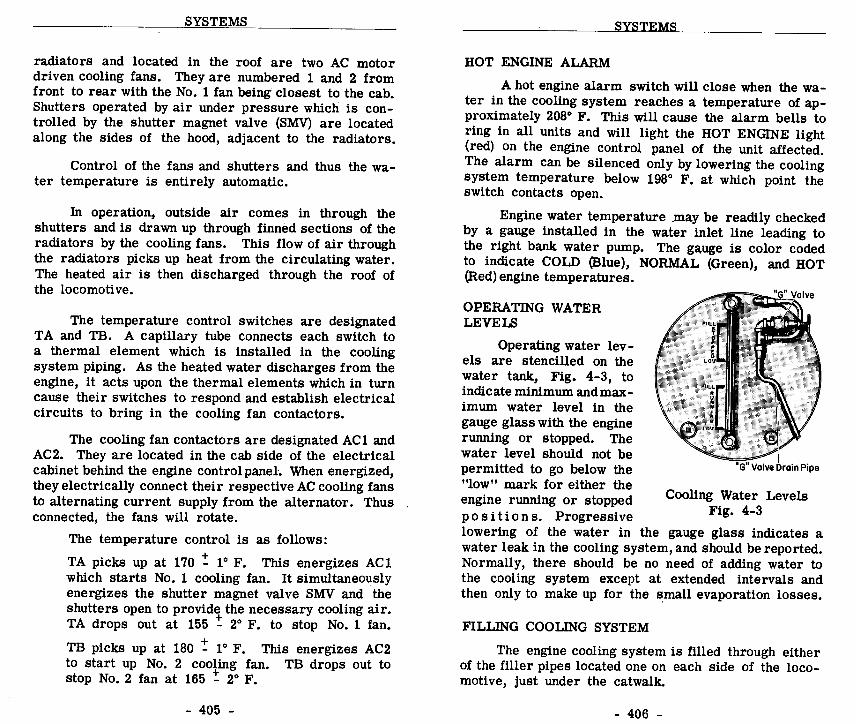
SYSTEMS
radiators and located in the roof are two AC motordriven cooling fans. They are numbered 1 and 2 fromfront to rear with the No. 1 fan being closest to the cab.Shutters operated by air under pressure which is con-trolled by the shutter magnet valve (SMV) are locatedalong the sides of the hood, adjacent to the radiators.
Control of the fans and shutters and thus the wa-ter temperature is entirely automatic .
In operation, outside air comes in through theshutters and is drawn up through finned sections of theradiators by the cooling fans .
This flow of air throughthe radiators picks up heat from the circulating water.The heated air is then discharged through the roof ofthe locomotive.
The temperature control switches are designatedTA and TB. A capillary tube connects each switch toa thermal element which is installed in the coolingsystem piping . As the heated water discharges from theengine, it acts upon the thermal elements which in turncause their switches to respond and establish electricalcircuits to bring in the cooling fan contactors.
The cooling fan contactors are designated AC1 andAC2. They are located in the cab side of the electricalcabinet behind the engine control panel. When energized,they electrically connect their respective AC cooling fansto alternating current supply from the alternator. Thusconnected, the fans will rotate .
The temperature control is as follows :TA picks up at 170 ± 1° F.
This energizes AC1which starts No. 1 cooling fan. It simultaneouslyenergizes the shutter magnet valve SMV and theshutters open to provide the necessary cooling air.TA drops out at 155 ± 2° F. to stop No. 1 fan .
TB picks up at 180 ± 1° F.
This energizes AC2to start up No. 2 cooling fan . TB drops out tostop No. 2 fan at 165 ± 2° F.
HOT ENGINE ALARM
SYSTEMS
A hot engine alarm switch will close when the wa-ter in the cooling system reaches a temperature of ap-proximately 208° F. This will cause the alarm bells toring in all units and will light the HOT ENGINE light(red) on the engine control panel of the unit affected .The alarm can be silenced only by lowering the coolingsystem temperature below 198° F. at which point theswitch contacts open.
Engine water temperature may be readily checkedby a gauge installed in the water inlet line leading tothe right bank water pump. The gauge is color codedto indicate COLD (Blue), NORMAL (Green), and HOT(Red) engine temperatures .
OPERATING WATERLEVELS
Operating water lev-els are stencilled on thewater tank, Fig. 4-3, toindicate minimum and max-imum water level in thegauge glass with the enginerunning or stopped. Thewater level should not bepermitted to go below the"low" mark for either theengine running or stoppedp o s i t i o n s .
Progressivelowering of the water in the gauge glass indicates awater leak in the cooling system, and should be reported.Normally, there should be no need of adding water tothe cooling system except at extended intervals andthen only to make up for the small evaporation losses.
FILLING COOLING SYSTEM
The engine cooling system is filled through eitherof the filler pipes located one on each side of the loco-motive, just under the catwalk .
Cooling Water LevelsFig. 4-3

SYSTEMS
Another fill line, capped by a knurled edge cap,is located near the top of the water tank inside thecarbody . This filler pipe is used when adding inhibitorto the cooling water. The engine should be running atidle speed when adding inhibitor .
To fill the cooling system proceed as follows :1 . Stop engine .
2 . Open "G" (overflow) valve.
3 . Fill slowly until water runs out the "G" valvedrain pipe.
4 . Close "G" valve.
If filling a dry or nearly dry engine also followthese additional steps :
5 . Start engine and run several minutes . This willeliminate any air pockets in the system.
6 . Shut down engine and open "G" valve and wait3 minutes .
7 . Add water until it runs out "G"valve drain pipe .
8 . Close "G" valve.
CAUTION : 1 . If the cooling system of a hot engine hasbeen drained, do not refill immediatelywith cold water.
If this is done, the sudden change in temperature might crack orwarp the cylinder liners and heads .
2. Do not attempt to fill the cooling systemthrough the drain pipe located underneaththe locomotive.
3 . The system should not be filled above themaximum water level indicated on the wa-ter tank to prevent :a . Freezing of radiators in winter when
engine is shut down.b . Loss of rust inhibitor when draining
back to "G" valve level .
SYSTEMS
DRAINING COOLING SYSTEM
Draining of the engine cooling system may becomenecessary in the event that the diesel engine is stoppedand a danger of freezing exists . By referring to Fig.4-2, the draining procedure is as follows :
1 . Open the main drain valve located at the floorin front of the engine. This will drain the en-gine, radiators, water tank, oil cooler, and aircompressor.
2 . The water pump on the right side of the enginewill not drain completely in the preceding step.To drain remaining water trapped in the pump,open the drain provided at the bottom of thehousing.
3 . With the cab heater supply and return valvesopen, the cab heaters and associated piping aredrained by opening the two drain valves locatedin the compartment under the cab floor at theleft side of the locomotive.
CAB HEATING AND VENTILATING
Cab heaters are complete with defroster and freshair ventilators . Fresh air is taken in through a louverin the cab wall and is controlled by a fresh air damperwithin the heater.
A 1/12th HP variable speed fan motor, controlledby a rheostat type switch, draws in fresh air or re-circulates cab air . The fan forces air through a hotwater radiator and exhaust the heated air out onto thecab floor.
The defroster is a simple nonadjustable baffle andduct arrangement and the volume, temperature, andvelocity of discharge air is dependent upon the settingof the fresh air damper, outlet damper, and speed ofthe fan motors.

Fresh air is controlled by the knob nearest thecab wall while the fan motor OFF-ON and speed controlknob is farthest from the cab wall. A small knob located on the outlet damper controls the amount of airentering the cab through this outlet .
Cab heater water is taken from the water pumpdischarge at the front end of the engine, as shown inFig. 4-2.
To obtain circulation of water through the cabheaters, the supply and return valves must be opened .
ENGINE WINTERIZATION
LUBRICATING OIL SYSTEM
ENGINE OIL SYSTEM
SYSTEMS
The winterization duct consists of a housing anda damper arrangement and No. 1 engine water coolingfan to divert, if desired, warm air into the engineroom. A handle on the outside of the duct controlsoperation of this winterization feature . The handle ismanually placed in the summer or winter position asdesired.
A schematic diagram of the lubricating oil systemis shown in Fig. 4-4. Oil under pressure is forcedthrough the engine for lubrication and piston coolingby the positive displacement combination piston coolingand lubricating oil pump. After circulating throughthe engine, the lubricating oil drains into the oil pansump. The positive displacement scavenging oil pumpdraws oil from the sump and strainer housing, thenforces it through the oil filter and cooler . From thecooler, the oil is delivered to another compartmentin the oil strainer assembly where it is ready forrecirculation by the combination piston cooling andlubricating oil pump.
ac
cm
m
m
SYSTEMS
O mc
mV
O
0
x0m
4
cdc.
O
cad
a
~ I 1
lI1
11
1
i
1I :il0:~t.1
_ O_
is_Do
100 ,

The lubricating oil pumps are mounted on thefront end of the engine and are gear driven by theengine accessory drive gear.
The oil strainer housingis also mounted on the front of the engine . The oilcooler and filter assemblies are located in the equip-ment rack adjacent to the front of the engine at the longhood end of the locomotive .
OIL LEVEL
The engine oil levelshould be checked with theengine hot and running atidle speed. Adipstick, Fig.4-5, is located on the rightside of the engine andshould show a level be-tween "Low" and "Full ."When the engine is stopped,
Checking Oil Levelthe oil in the filter and
Fig. 4-5cooler will drain back intothe oil pan. If the oil levelis checked with the enginestopped, the reading on thedipstick will be above theFULL mark.
ADDING OIL TO SYSTEM
SYSTEMS
Oil maybe added withthe engine running orstopped. When oil is addedto the system, it MUST bepoured into the strainerhousing through the open-
Adding Oil To Engineing having the- square cap,
Fig. 4-6as shown in Fig. 4-6.Should the round caps be removed while the engine isrunning, hot oil under pressure will come from theopenings and possibly cause personal injury .
Strainer Drain ValveOpen ONLY if draining
the engine oil pan
OIL PRESSURE
An engine oil pressure gauge is located below thewater tank on the equipment rack, at the right bank sideof the engine .
Engine lubricating oil pressure should beapproximately 70 psi at full engine speed and about 35psi at idle speed. These pressures may be somewhatlower however, due to changes in oil temperature andviscosity.
LOW OIL PRESSURE PROTECTION
In the event of low oil pressure in the engine lubri-cating oil system, the governor low oil pressure protec-tive device will act to shutdown the engine . This deviceis built into the governor and when tripped, causes asmall button, Fig. 4-7, to protrude from the front of thegovernor far enough to expose a red ring on its stem.Oil under the governor power piston then drains allowingthe power piston spring to move the layshaft and injectorracks to the no fuel position, stopping the engine . Thealarm bells will ring in all units and the low oil light willbe illuminated in the unitaffected . The alarms willcease when the governorbutton is manually reset.
FUEL OIL SYSTEM
GENERAL DESCRIPTION
SYSTEMS
A schematic diagramof the fuel oil system isshown in Fig. 4-8 . Fuelis drawn from the storagetank through a suction fuelstrainer by the motordriven gear type fuel pump .From the pump the fuel is forced to the filter mountedon the engine . After passing through the double elementengine mounted filter, the fuel flows through manifoldsthat extend along both banks of the engine .
Governor Low OilPressure Device
Fig. 4-7

SYSTEMS
0
L
02
O
Gv
SYSTEMS
These manifolds supply fuel to the injectors . Theexcess fuel not used by the injectors returns to the fueltank through the return fuel sight glass, mounted on thefilter housing. A restriction inside the return glasscauses a back pressure thus maintaining a positive sup-ply of fuel for the injectors .
The fuel pump delivers more fuel to the enginethan is burned in the cylinders . The excess fuel cir-culated is used for cooling and lubricating the fine work-ing parts of the injectors .
FUEL SIGHT GLASSES
Two sight glasses, Fig . 4-9, are located on theengine mounted filter housing to give visual indicationof fuel system condition .
For proper engine operation, a good flow of fuel(clear and free of bubbles)should be visible in thesight glass nearest theengine called the "returnfuel sight glass." The fuelflowing through this glassis the excess not requiredby the engine . Upon leav-ing the glass it returns tothe fuel tank for recircu-lation .
The engine mountedfilter is also equipped witha by-pass relief valve andsight glass . This sightglass, located furthest fromthe engine, i s normallyempty. When more than atrickle of fuel is seen inthe by-pass sight glass, itindicates that the relief
Fuel Oil Sight Glassesvalve is open. Fuel will
Fig. 4-9
1
OO~00O OO O .g
-00000000

FILLING FUEL TANK
SYSTEMS
pass through the by-pass sight glass and relief valveto by-pass the engine and return to the fuel tank inthe event the filter elements become clogged. Thiscondition may become serious enough to cause theengine to starve for fuel and thus shut down.
The fuel tank can be filled from either side of thelocomotive. A short sight level gauge is located nextto each fuel filler . This fuel gauge indicates the fuellevel from the top to about 4-1/2" below the top of thetank and should be observed while filling the tank toprevent overfilling . DO NOT HANDLE FUEL OIL NEARAN OPEN FLAME .
EMERGENCY FUEL CUTOFF VALVE
An emergency fuel cutoff valve is provided to cutoff the fuel supply to the fuel pump in the event of fire,or any emergency . It is located in a closed compartment at the lower left rear corner of the fuel tank.On each side of the locomotive, at the top rear cornerof the fuel tank, is a small box with a lift cover. En-closed in this box is a pull ring on the end of the cablerunning to the fuel cutoff valve. A similar ring is lo-cated in the cab of the locomotive . The fuel cutoff valvecan be tripped by pulling any one of these three rings .If tripped, the valve must be reset manually .
To reset the valve, the "U" control rod extendingfrom the valve compartment should be pulled OUT asfar as possible . See Fig. 4-10 .
AIR SYSTEM
DESCRIPTION
Compressed air is not only used on a diesel lo-comotive for operating the air brakes and sanders, butis also essential for the proper operation of many other
items. The shutter operating cylinder, horn, bell andwindshield wipers are also air operated . Air is alsorequired for atomizing the fuel oil on units equippedwith a steam generator .
AIR COMPRESSOR
Compressed air is received from a water cooled,6 cylinder, two stage air compressor driven througha flexible coupling from the front end of the enginecrankshaft.
SYSTEMS
TRIPPED POSITION
SET POSITION
Emergency Fuel Cutoff ValveFig . 4-10

SYSTEMS
The compressor has its own oil pump and pressurelubricating system. With the engine running, the levelin the compressor crankcase can be checked on thefloat type indicator. At idle speed (275 RPM) and withthe compressor crankcase oil hot, the lubricating oilpressure should be approximately 15 to 20 pounds (nogauge provided) .
The compressor has four low pressure and twohigh pressure cylinders . The pistons of all six cylindersare driven by a common crankshaft. The four low pressure cylinders are set at an angle to the two verticalhigh pressure cylinders . Air from the low pressurecylinders goes to a water cooled intercooler to be cooledbefore entering the high pressure cylinder . The inter-cooler is provided with a pressure gauge and reliefvalve. The gauge normally reads approximately 50 to55 pounds when the compressor is loaded. The inter-cooler relief valve is set for 65 pounds . Any markeddeviation of intercooler pressure from 50 to 55 poundsshould be reported at the maintenance terminal .
It is important to drain the compressor intercooler(two drain valves are provided in the bottom header)and the main reservoirs to prevent moisture and dirtfrom being carried into the air brake and other airsystems .
COMPRESSOR CONTROL
Since the air compressor is directly connected tothe engine, the compressor is in continuous operation(although not always pumping air) whenever the engineis running. An unloader piston is provided in the headof each high and low pressure cylinder which cuts outthe compressing action when actuated by air pressurefrom the compressor governor control . The unloaderaccomplishes this by blocking open the intake valve ofthe high and low pressure cylinders . When the air op-erating the unloader is cut off, the unloader releasesthe intake valves and the compressor resumes pumping .Main reservoir air pressure is used to actuate the un-loader valves.
SYSTEMS
Two methods of compressor governor control areused: (1) Pneumatic governor control (basic for singleunits), and (2) Electro-pneumatic governor control (usually used on units equipped for multiple unit operation).
1 . Pneumatic Control
On locomotives with the pneumatic governorcontrol system, each air compressor operatesas an individual componentwithout regard to themain reservoir demands of other units in theconsist . When the main reservoir air pressurereaches 140 pounds, the governor "cuts out" theair compressor by admitting air to the unloadervalves. Admitting air to the unloader valveswill hold the intake valves open stopping thecompressing action. The compressor remainsunloaded until the main reservoir pressure fallsto 130 pounds .
The governor then "cuts in" theair compressor by stopping the air supply to theunloader valves, releasing the intake valves andthe compressor resumes pumping .
2 . Electro-Pneumatic Control
If all the units of a locomotive consist areequipped with the electro-pneumatic system ofcompressor governor control, Fig. 4-11, theelectrical arrangement is such that all com-pressors in the locomotive are synchronized topump air into their respective main reservoirswhen the main reservoir pressure in any oneunit drops to 130 pounds. When the air pres-sure in all reservoirs reaches 140 pounds, thecompressors will unload.
Each unit. i s equippedwith a compressor controlswitch (CCS) actuated by main reservoir pres-sure, a compressor control magnet valve anda compressor relay (CR). A compressor con-trol wire (CC) runs throughout the locomotiveand connects the compressor relays in each

SYSTEMS
0U;.00
0 'U
0UW
SYSTEMS
unit in parallel . This electro-pneumatic gov-ernor control is located on the equipment rack.
The compressor control switch may be con-sidered to be a single-pole double-throw switchthat is thrown to the "loaded" position when themain reservoir pressure drops to 130 pounds,or to the "unloaded" position when the mainreservoir pressure reaches 140 pounds . In theunloadedposition the CCS causes the compressorcontrol magnet valve to be energized, allowingair to pass through the valve to the compressorunloader pistons stopping the compressing action .In the unloaded position the CCS breaks the cir-cuit to compressor control magnet valve in thatunit and causes current to flow through the CCwire energizing the CR relays in each unit .When the CR relay is energized its interlockbreaks the circuit to the compressor controlmagnet valve regardless of the position of theCCS in that unit. Breaking the circuit to thecompressor control magnet valve shuts off thesupply of air to the compressor unloader pis-tons, and the compressor resumes pumping .
MANUAL UNLOADER VALVE
On pneumatic governor installations, a three-wayvalve is provided in case it is desired to keep an aircompressor unloaded .
A raised "T" pattern on the faceof the valve indicates the flow of air through the valve.The valve is normally positioned so as to direct the airsupply to the unloader valves through the compressorgovernor control . To manually unload the air compres-sor, turn valve to by-pass main reservoir air supplyto the unloader valves around the compressor governorcontrol .
On electro-pneumatic governor control systems,a means is also provided for keeping an air compressor

unloaded .
In this case, the method used is to mechan-ically hold the button depressed and air valve open onthe compressor control magnet valve. The mechanicalarrangement is mounted above the magnet valve and canbe readily positioned by turning the knob provided .
DRAINING AIR SYSTEM
SYSTEMS
The air system should be drained periodically toprevent moisture from being carried into the air brakeand other air systems .
The frequency of draining willdepend on local conditions and can be determined bypractice. It is recommended that draining be done atthe time of each crew change, until a definite schedulecan be determined by the individual railroad .

SECTION 5
ELECTRICAL EQUIPMENT
INTRODUCTION
The diesel engine drives three electrical genera-tors each of which then supplies electrical energy re-quired for locomotive operation. Basically, the maingenerator furnishes power to the motors for locomotivetraction ; the alternator supplies power to drive auxil-iaries such as fans and blowers ; the auxiliary generatorsupplies low voltage electricity for the control circuits .
In order to control these generators as well asthe circuits and equipment to which they supply power,it is necessary to use electrical devices called relays,contactors, switches, circuit breakers and regulators.As a group, such equipment is referred to as electricalswitchgear. This switchgear is housed in an electricalcabinet which forms the rear portion of the cab .
This section of the manual describes the functionof the generators and switchgear components . The in-formation is presented only for a better understandingof locomotive operation . This equipment all functionsautomatically, without any attention required on the partof the engineman . Electrical cabinet doors should alwaysremain closed during operation .
MAIN GENERATOR
The main generator, Fig. 5-1, is a specially de-signed constant kilowatt (power) generator . A givenamount of 'electrical power will be produced from theinput of a given amount of mechanical power . Sincepower in watts is the product of volts times amperes,it can be seen that with a constant kilowatt generator,if the volts increase the amperage decreases, and viceversa.

ELECTRICAL EQUIPMENT
The output voltage of the main generator is con-trolled by the extent towhich the main generatorisautomatically excited, andby the speed of the engine.The high voltage directcurrent electricity fromthe main generator is ratedat a nominal 600 volts .
The following fieldwindings are built into thegenerator. Main Generator
And Alternator1 . Starting - This
Fig. 5-1field is used onlyfor starting the diesel engine . When energizedwith low voltage battery current it temporarilymakes a motor out of the generator to crankthe diesel engine.
2. Battery - The battery field is separately excitedby low voltage current from the auxiliary gener-ator. It is energized by the closing of the bat-tery field (BF) contactor to provide initial gener-ator excitation . This field has the load regulatorand a protective fuse in its external circuit.The electrical output of the generator is con-trolled by varying the excitation of this field.
3 . Shunt - The shunt field is self-excited by themain generator through an external circuit con-trolled by the shunt field (SF) contactor . Thisfield assists the battery field in building upgenerator output .
4. Differential - The differential field is used toobtain the constant kilowatt characteristics de-sired in the main generator . It does so byopposing the battery and shunt fields,and func-tions to reduce generator excitation at highgenerator amperages.
5. Commutating - This field is wound on the gen-erator interpoles to provide proper commutation.
6. Compensating - The compensating field is com-posed of a group of windings embedded in theface of the main poles . The purpose of thisfield is to minimize distortion of the field fluxset up by the armature current and to providebetter commutation.
The differential, compensating and commutatingfields are permanently connected and are a matter ofengineering design providing desired generator charac-teristics and proper commutation .
TRACTION MOTORS
ELECTRICAL EQUIPMENT
Electrical power from the main generator is dis-tributed to the four traction motors, Fig. 5-2, which aremounted in the trucks .
Each motor is geared to a pairof wheels, thus all wheels are drivers . Electro-magneticpower contactors connect the main generator to themotors in circuits for proper operation. These circuitswill change automatically to permit full power utilizationover the complete range of locomotive operation. Thesepower circuit changes are called transition .
The locomotive is reversed by changing the direc-tion of current flow through the traction motorfieldwind-ings, while current flowdirection through the arma-ture remains the same.This is accomplished bythe electro-magnetic re-versing contactors estab-lishing the circuits neces-saryfor operation in eitherdirection.
The traction motorsareseries wound to provide
Traction Motorthe high starting torque
Fig. 5-2

characteristics desired for locomotives . They aredesigned for heavy duty operation and are cooled bymeans of external air blowers located in the locomotiveunit .
ALTERNATOR
The alternator, Fig . 5-1, is a part of the maingenerator assembly, having its stator bolted to the gen-erator frame and rotor connected to the armature .Alternator output voltage and frequency vary with thespeed of rotation . At full engine speed of 835 RPM,alternator output is 170 volts AC at 111-1/3 cycles persecond .
The alternator rotor (field) is excited by lowvoltage current received from the auxiliary generatorthrough a pair of slip rings and brushes .
With the exception of a 60 ampere protective fuse,there are no contacts or other controls in the circuit,thus the alternator will be excited and developing powerwhenever the diesel engine is running.
qi A2
ELECTRICAL EQUIPMENT
Auxiliary Generator 10 KW And 18 KWFig. 5-3
ELECTRICAL EQUIpMENT
AUXILIARY GENERATOR
All low voltage direct current electricity requiredduring locomotive operation comes from the auxiliarygenerator, Fig. 5-3.
This current is used for excitationof the main generator and alternator as well as forenergizing control circuits and actuating electricalswitchgear components .
The auxiliary generator is a self-excited machineusing residual magnetism for initial excitation . To holdvoltage output at a constant 74 volts, a voltage regulatoris used in the field excitation circuit . This devicevaries excitation current as necessary to compensatefor changes in generator rotating speeds .LOAD REGULATOR
Essentially the load regulator, Fig. 5-4, is anautomatically operatedrheostat connected inseries with the batteryfield of the main generator .
The load regulator isa self-contained unit whichconsists of a hydraulic vanetype motor connected to acommutator type rheostat.Engine oil pressure is usedto move the vane motorand vary the position ofthe rheostat brush arm.Oil under pressure can bedirected to either side ofthe vane, as controlled bythe load regulator pilotvalve, located in the en-gine governor .
For the purpose ofload regulation an arbi-
Load Regulatortrary relationship has been
Fig . 5-4

ELECTRICAL CABINET
ELECTRICAL EQUIPMENT
established by means of governor linkage between theengine throttle settings and the amount of fuel injectedat each setting . In other words, there is a definiterate of fuel consumption for each throttle position whenthe engine is loaded. If the load on the engine be-comes such that more fuel is demanded to maintainengine speed, the load regulator pilot valve will causethe load regulator to reduce the engine load the re-quired amount by reducing the battery field strength.
If on the other hand the load on the engine be-comes such that less fuel is required to maintain enginespeed, the load regulator pilot valve will cause the loadregulator to increase engine load the necessary amountby increasing the battery field strength.
In t h i s
manner,
battery voltage,
temperaturechanges in the generator windings, or locomotive speedsdo not cause overloading or underloading of the engineand a constant power output is maintained for eachthrottle setting.
An overriding solenoid, ORS, located in the gov-ernor can override the normal action of the load reg-ulator pilot valve.
When the ORS is energized it forcesthe load regulator pilot valve to cause engine oil underpressure to move the load regulator toward the mini-mum field position, unloading the engine. The ORSis energized during transition and wheel slip action .
An electrical cabinet which houses the majorityof the locomotive electrical switchgear forms the rearwall of the locomotive cab.
This equipment is locatedon both the cab and engineroom sides of the cabinet .Although access doors are provided, they should bekept closed at all times during operation .
- 505 -
ELECTRICAL EQUIPMENT
A. CAB SIDE EQUIPMENT - Fig . 5-5
The cab side of this cabinet is shown in Fig. 5-5.The functions of the various pieces of equipment areas follows :
1 . CONTROL PANEL SWITCHES
Thefuses, switches andotherequipment mountedon the control panel are fully described in Section2 of this manual covering cab controls .
2 . FUEL PUMP CONTACTOR, FPC
The FPC in each unit is energized by closingthe control and fuel pump switch on the control-ler of the lead unit . This partially establishesa circuit to the individual fuel pump motors.These circuits are completed and the individualpumps will run when the fuel pump circuitbreaker in each unit is closed.
3 . PNEUMATIC CONTROL RELAY, PCRIf the pneumatic control switch, PCS, trips dueto a penalty application of the air brakes, itdrops out the PCR which in turn opens the ERcircuit which is trainlined throughout the loco-motive . All ER relays are then de-energizedand all engines are reduced to IDLE speed andpower . The PCR resets when the air brakesare recovered and throttle is placed in IDLE.
4. ENGINE RUN RELAY, ERThe ER relay has contacts in the circuits be-tween the throttle and the engine speed controlsolenoids in the governor. In normal operation,the ER relay is energized, its contacts areclosed permitting engine speed to respond tothrottle position . During certain electrical dif-ficulties however, such as ground relay action,the ER relay is de-energized, opening the circuitcausing engine speed to be reduced to idle, or
- 506 -

ELECTRICAL EQUIPMENT
Electrical Cabinet - Cab SideFig. 5-5
ELECTRICAL EQUIPMENT
if the throttle is in the 5th or 6th position, theengine will stop.
5 . FORWARD RELAY, FOR
The forward relay, FOR, is energized whenthe reverse lever is placed in the Forward po-sition . Its contacts complete circuits so thatthe electro-magnetic forward reversing con-tactors, RVF1 and RVF2, are energized . Thesecontactors in each unit receive local controlpower from their respective auxiliary genera-tors, yet their operation is trainlined throughtheir control relay.
6, REVERSE . RELAY, RER
Same as FOR, but energized for reverse lo-comotive operation .
7 . AUXILIARY WHEEL SLIP, AWS
The auxiliary wheel slip, when used, is a relayused in conjunction with wheel slip relays toincrease the number and size of contacts avail-able for generator unloading in power as wellas during dynamic braking.
8. TRANSITION RELAY, TR
The transition relay when energized sets up thenecessary circuits to change traction motorconnections from series-parallel to parallel .
9 . WHEEL SLIP RELAYS, WS36, WS5 AND WS14
The wheel slip relays are connected in the elec-trical circuits to detect differences in currentflow between pairs of traction motors. Suchdifferences indicatewheel slippage . When ener-gized, the relays establish circuits to initiate-automatic sanding, partial unloading, or if nec-essary, full unloading of the power plant .

ELECTRICAL EQUIPMENT
10 . LOAD REGULATOR CONTACTOR, LRC
The LRC cuts out the quick starting featurewhen it is energized through the LRS switchlocated in the governor.
11 . GROUND RELAY, GR
The ground relay is a protective device andfunctions to detect high voltage grounds duringoperation or low voltage grounds when the dieselengine is started . When tripped, alarms willfunction and the engine inthe unit concernedwillgo to idle, or if the throttle is in the 5th or6th position it will stop. It is reset by a pushbutton on the engine control panel.
12 . REVERSE CURRENT RELAY
The reverse current relay (RCR) functions inresponse to auxiliary generator voltage outputto control the operation of battery chargingcontactor (BC) . When the auxiliary generatorvoltage approaches its normal value of 74 volts,the RCR causes the BC contactor to close thusconnectingthe auxiliary generator to the storage .battery and low voltage system of the locomo-tive . The battery will then be charged sincethe auxiliary generator's 74 volts potential isgreater than the storage battery's 64 volts .
In instances where the auxiliary generatorvoltage falls below normal operating value orthat of the battery, the RCR again functionscausing the BC contactor to open and disconnectthe generator from the battery. This preventsa reversal of current from the storage batteryattempting to motorize the auxiliary generator .The RCR and the rectifier beneath it (to pre-vent contact arcing) need no attention and shouldnot be disturbed during operation .
ELECTRICAL EQUIPMENT
13. SHUNT FIELD CONTACTOR, SF
This contactor closes during operation wheneverthe throttle is opened with the generator fieldswitch ON. It completes a circuit allowing forthe self-excitation of the main generator .
14. BATTERY FIELD CONTACTOR, BF
The BF contactor, controlled by interlocks ofthe following SF contactor, provides primaryexcitation of the main generator from the loco-motive low voltage system. This contactor isclosed during operation but opens during tran-sition or wheel slip action to reduce maingenerator output .
15 . FIELD SHUNT TIME DELAY, FSD
The field time delay relay energizes the ORSin the governor 2 to 3 seconds prior to closingof the FS2 contactor during field shunting inparallel connection. This action provides fora smoother field shunting step .
16 . TIME DELAY SANDING RELAY, TDS
With the automatic sanding switch ON duringwheel creep or slip action, the TDS is energizedcausing a timed amount of sand to be applied .
17. BATTERY CHARGING CONTACTOR, BCThe battery charging contactor connects theauxiliary generator to the storage battery andlocomotive low voltage system. It opens toprevent reversal of current flow from motoriz-ing the generator in instances where the engine(and generator) are stopped. The BC contactoris controlled bythe reverse current relay (RCR)which functions in response to generator voltage .

ELECTRICAL EQUIPMENT
18. BRAKE MOTOR FIELD CONTACTOR, BK
This relay is used during dynamic braking tocomplete the circuit of all traction motor fieldsin series to the main generator armature. Whengoing from dynamic braking to power, the BKcontact opens first since it is equipped for arcdischarge .
19 . PARALLEL POWER CONTACTORS, P14,P25 AND P36
These electro-magnetic contactors are energizedand closed during transition to connect the trac-tion motors in a 3 group parallel circuit withthe main generator . Further information maybefound in Section 6 covering electrical circuits .
20 . SERIES POWER CONTACTORS, S43 AND S23
These electro-magnetic power contactors closeto establish a 2 group parallel circuit betweenthe traction motors and main generator . Theywill open automatically during transition . Fur-ther information may be found in Section 6covering electrical circuits .
21. WHEEL CREEP RELAY, WCR
The wheel creep relay WCR is almost the sameas the wheel slip relay WS except for sensitivityof setting . It detects minute electrical unbalancebetween motors, and initiates automatic sandingbefore an actual wheel slip occurs . The wheelslip relay functions to provide for gradual un-loading of the power plant in the event of a truewheel slip .
22. WHEEL SLIP SERIES RELAY
At very slow speeds, if the wheel slip cannotbe corrected through actionof the WCR applyingsand to the rails, the WSS picks up to reducemain generator excitation.
ELECTRICAL EQUIPMENT
B. ENGINEROOM SIDE EQUIPMENT - Fig. 5-6
Additional electrical devices on the opposite orengineroom side of the electrical cabinet are identifiedand described below .
1 . DYNAMIC BRAKE REGULATOR, DBR
Used on units equipped with dynamic brakes,the DBR functions to regulate main generatorexcitation so that the maximum braking effortof 700 amperes is not exceeded . Automatic inoperation, it prevents overloads by causingcurrent to flow through the generator shuntfield windings in a reverse direction, thusbucking the battery field excitation .
2 . BRAKE WARNING RELAY, BWR
Used on units equipped for dynamic braking,the BWR is energized in the event that the max-imum braking effort of 700 amperes is exceeded.It functions only to light the warning light onthe cab controller and thus alert the enginemanto the overloaded condition . The light goes outwhen braking current is reduced to a safe level .
3 . GENERATOR FIELD RELAY, GFR
An auxiliary relay energized when the throttleis opened for power, it functions to preventtraction motor field shunting contactors fromclosing unless locomotive is in power. It alsofunctions to establish the load regulator in apotentiometer circuit for better excitationcontrol .
4 . BRAKE RELAY, BR
When changing from power to dynamic braking,interlocks of BR relay are utilized in energizingand de-energizing various relays to give theproper dynamic braking circuits .

ELECTRICA L EQUIPMENT
Electrical Cabinet - Engine Room SideFig. 5-6
ELECTRICAL EQUIPMENT
5. HUMP RELAY, HC
The hump relay, when used, disconnects thefast start feature during humping operations .It also sets up circuits for trainlining the humpcontrol.
6. HUMP CONTROL RELAY, HCR
The HCR is a micropositioner device used duringhump control. It functions to set up a balancebetween the load regulator and the hump controlrheostat through the ORS, to control the loadingand unloading of the engine.
7. LOAD REGULATOR POSITIONER, LRP
The LRP is a micropositioner device used dur-ing dynamic braking. It functions to set up abalance between the load regulator and the dy-namic brake rheostat in the controller . Thepurpose is to control the load regulator andthus control dynamic brake field loop strength .
8. SHUNT FIELD TRANSFER RELAY, SFT
Used only on units equipped with dynamic brakes,the SFT functions during such operation to con-nect the dynamic brake regulator into the maingenerator shunt field circuit. It also providesfor a reverse direction of current flow throughthis field during regulation on the part of theDBR.
9. FIELD LOOP CONTACTOR, FL
Used on units equipped with field loop control,the field loop contactor establishes a circuitwhich places the battery fields of all main gen-erators in series . Generator excitation anddynamic braking strength is then controlled byregulating the strength of current flowing in thecircuit. The FL contactor is energized onlyin the lead or controlling locomotive unit.

ELECTRICAL EQUIpMENT
10. POWER BRAKE SWITCHGEAR, BKB3 ANDBKB4This is a large contactor used to make highvoltage connections in the circuits of main gen-erator, traction motors anddynamic brake gridsrequired during dynamic braking.
11 . POWER BRAKE SWITCHGEAR, BKP1AND BKP2
These are large contactors used to make highvoltage connections in the circuits of main gen-erator, traction motor and dynamic brake gridsas required during power operation and dynamicbraking. BKP1 and 2 are energized in power.
12 . MOTOR FIELD SHUNTING CONTACTOR, FS1AND FS2
During the proper transition position, thesecontactors connect the field shunting resistorsin parallel with the traction motor fields . Thesecontactors are used in all field shunting posi-tions .
13 . REVERSER SWITCHGEAR - REVERSE,RVR5 AND RVR36The electro-magnetic reversing contactors areactuated by the reverse relay, RER, in responseto reverse lever position in the cab . The con-tactors are energized by local control powerfrom the low voltage system in each unit .
Theycontrol the direction of current flow throughthe motors for reverse rotation .
14 . REVERSER SWITCHGEAR - FORWARD,RVF2 AND RVF14
Electro-magnetic contactors are used to con-trol the direction of current flow through thetraction motors and thus control their direction
ELECTRICAL EQUIPMENT
of rotation. The forward reversing contactorsare energized when the reverse lever is placedin the forward position . They are energizedby local control power supplied by action ofthe forward relay, FOR.
15 . MOTOR FIELD SHUNTING RELAY, FSR1AND FSR2During transition, this relay sets up circuitsto field shunting resistors in parallel with thetraction motor fields . It is operative duringboth major steps of transition.
16 . PARALLEL TRANSITION RELAY, PTR
This relay is used to set up the circuit to changethe motor connections from series-parallel tofull parallel during transition .
17. GENERATOR (ENGINE) STARTINGCONTACTOR, GS
The GS contactor is used to supply battery cur-rent to motor the main generator for enginestarting when the engine start button is pressed .
SECTION 6ELECTRICAL SYSTEMS
INTRODUCTION
Electrically, the locomotive can be thought of asbeing divided into the following three separate systems :
1 . High voltage direct current system (includesdynamic braking system - if used) . Nominally600 volts .
2 . Low voltage direct current system. Regulatedto 74 volts .
3 . Alternatingcurrent system. Maximum 170 volts .
The high voltage system is directly concerned withmoving the locomotive; or in retarding the locomotive(dynamic brakes) . The main components of the highvoltage system are the main generator, traction motors,transition relays, shunt field contactors, motor shuntingcontactors, reverser contactors, wheel slip relays,ground relay, power contactors, braking contactors,braking resistor grids and grid blower motors.
The low voltage system contains the circuits whichcontrol the flow of power in the high voltage system,and those auxiliary circuits conducting power to thelocomotive lights, heater fans, fuel pump, and the maingenerator battery field . A 64-volt battery, in the lowvoltage system, is the source from which power istaken to start the diesel engine. Once the engine isstarted, the auxiliary generator takes over to supply74 volts for operation of all low voltage circuits andequipment .
The alternator supplies AC power for operation ofthe two motor driven cooling fans and the electricallyoperated traction motor blower . Use of AC inductionmotors for direct drive of these important auxiliariesprovides for efficient, trouble free operation .

ELECTRICAL
Functions of the individual electrical devices thatoperate in these electrical systems are discussed else-where in this manual. This particular section is devoted to electrical circuits and their functions duringlocomotive operation.
TRACING SCHEMATIC WIRING DIAGRAMS
An understanding of how to trace a schematicwiring diagram is helpful to anyone desiring a greaterknowledge of the electrical operation of the locomotive.It is also valuable for purposes of trouble shootingwhen electrical difficulties arise.
The circuits that will be traced are those thatare basic to the operation of the locomotive . Theyinclude the fuel pump, engine starting, reversing,control and excitation circuits . Before tracing thesecircuits, the following electrical fundamentals shouldbe understood.
1 . A complete circuit or path must exist beforeelectricity will flow and perform a desiredfunction. Thus, starting from a source of elec-tricity such as a battery or generator, currentwill flow through wires, switches and contactsproviding that the path is uninterrupted back tothe original source . The flow of electricity willbe traced starting at the positive (+) side of asource and ending at the negative (-) side.
2 . A contactor or relay will function when its as-sociated operating coil is energized . Currentflowing through such coils creates the magneticforce necessary to actuate the contacts . Thecontacts, which are a part of the contactor orrelay, will then open or close as the case maybe, to make or break other electrical circuits .
3 . Almost all contactors and relays are equippedwith interlocks. These interlocks, Fig. 6-1, are
No Power To Coil
Main contact normally openInterlock AB normally openInterlock CD normally closed
A B_
N.O . interlocks
B4
ELECTRICAL
actuated together with the main contacts bythe energizing or de-energizing of the operatingcoil and they function to make or break low volt-age control circuits to achieve desired results .
These interlocks will be in their normal posi-tion, either open or closed, when the operatingcoil is not energized . When the coil is ener-gized, they change position ; thus the normally
a
Power Applied To Coil
Main contact now closedNormally open AB interlocknow closed
Normally closed CD interlocknow open
Shown schematically on a wiring diagram, the normally open(N.O.) interlock is either below a horizontal line or to the rightof a vertical line . The normally closed (N.C .) interlock isshown above or to the left side of a line .
Contact And Interlock OperationFig. 6-1

ELECTRICAL
closed interlocks will open. When the coil isde-energized, the interlocks return to theirprevious normal position.
4 . Most schematic wiring diagrams are drawn il-lustrating a "dead" locomotive with all switchesopen, controls off, and electrical contactors andrelays de-energized. Thus all contacts and in-terlocks are shown in their normal position .Such normal positions will change as the variouscontactors and relays are energized during thecourse of circuit tracing.
Before attempting to trace circuits, it is recom-mended that the legend of electrical equipmentlocated at the end of this section be studied indetail . This will prove valuable in identifying thevarious electrical components on the diagrams.
FUEL PUMP CIRCUIT, Fig. 6-2
The fuel pump circuit must be established beforestarting the engine and it must remain functioning dur-ing all phases of locomotive operation . This circuit isshown in Fig. 6-2 .
The first portion of this circuit is that which istrainlined from the lead or controlling unit to all unitsin the locomotive consist. It is established by closingthe main battery switch to energize the BP wire, thenby placing the 30 ampere control circuit breaker ON,and the control and fuel pump switch ON, the circuitis completed to the PC wire . The PC wire is train-lined and serves to energize the fuel pump contactorFPC in each unit . The circuit is completed back tothe lead unit storage battery by means of the N wire .
In each unit, the A-B and C -D contacts of the FPCwill be closed to partially establish a circuit to the fuelpump motor. The circuit is completed and the motorwill run when the main battery switch is closed andthe 15 ampere fuel pump circuit breaker is placed ON.
- 603 -
ELECTRICAL
From the foregoing, it can be seen that individ-ual fuel pumps can be started or stopped by means ofthe 15 ampere circuit breaker .
Similarly, with the individual circuits established, the operation of all fuelpumps in a multiple unit locomotive could then be con-trolled from the control and fuel pump switch in thecab of the lead unit .
ENGINE STARTING CIRCUIT, Fig. 6-2Referring to Fig . 6-2, the engine is started as
follows :
BNFuel Pump
Motor
GS
BN
64 Volt Storage Battery
IIIIIII IIIIIII +
D C
r---- 15Amp,I
FPC
L _
"_IFuel Pump MotorCircuit Breaker
BP
o D
.TB PC
FPC
Control B Fuel Pump Switch
30 Amp ControlCircuit Breaker
GS
Start
is ,A
Bl
Start Comm. Diff . /__ . N
400A .
T*G
Fuel Pump And Starting CircuitFig. 6-2
- 604 -
StartingFuse

ELECTRICAL
With current flowing through the PC wire (pre-viously energized) a circuit leads to the isolation switch .When in the START position as shown, pressing theSTART push button completes the circuit to the startingcontactor coil (GS) .
The GS contacts will now close in the main gen-erator circuit . This allows battery current to flow fromthe BP wire through the 400-ampere starting fuse; GScontact, main generator armature, generator field wind-ings including the starting field, and through another GScontact to complete the circuit to the BN wire. Themain generator now operates as a motor to crank andstart the diesel engine .
LOCAL CONTROL CIRCUITS
The heavy-duty reversing, power and braking con-tactors are electro-magnetically actuated which involvethe use of trainlined as well as local control circuits .
From the controls in the cab, trainlined controlcircuits are established which provide the signal to ac-tuate the switchgear in each unit .
The switchgear however is actually operated by local low voltage powerreceived from the auxiliary generator in each unit.
This arrangement is necessary since if all theelectro-magnetic switchgear was both controlled andoperated by trainlined circuits, the current drawn fromthe lead unit auxiliary generator would be excessive.Thus the lead unit simply sets up controlling circuitswhile the auxiliary generators in the individual unitsprovide the power to actuate the switchgear components.
The actual functioning of the local control circuitmay be found in the explanation of the reversing andcontrol circuits which follow .
ELECTRICAL
REVERSING CIRCUIT, Fig . 6-3
To control the direction of locomotive movement,electro-magnetic reversing contactors are used to es-tablish the proper circuits through the traction motors.The operation of this circuit is shown in Fig. 6-3 andis described below.
From the previously energized PC wire, a circuitleads to the selector portion of the controller. Withthe lever placed in No. 1 position and the reverse leverin FORWARD, the current then flows in the FO train-line wire which runs throughout the locomotive consist .From this wire, a circuit energizes the forward relay(FOR) which results in its contacts FOR A-B closingin circuit leading to the forward reversing contactors,RVF14 and RVF2 .
Closing the local control circuit established a cir-cuit from the auxiliary generator and PR wire, thenthrough the 30-ampere local control circuit breakerto energize the POA wire. A circuit coming fromthe local control wire, POA, leads through normallyclosed interlocks G-H of RER, C-D of RVR36, C-D ofRVR5 and the now closed A-B of FOR, through RVF14and RVF2 A-B interlocks to energize the coils of theforward reversing contactors RVF14 and RVF2. As themagnetic coils are energized, the G-H interlocks forRVF14 and RVF2 close to establish their own holdingcircuits . At the same time, the A-B interlocks forRVF14 and RVF2 open, inserting 50 ohm resistors inseries with the reversing contactor coils. This reducesthe current drawn from the local control circuit . Themain contacts of these contactors (not shown) are nowclosed in the high voltage circuit to connect the tractionmotors for forward rotation .
Operation in reverse is similarly accomplished,but in that case the RE trainline wire is energized bring-ing in the reverse relay RER which in turn energizesthe reverse reversing contactors RVR36 and RVR5 .

ELECTRICAL
Reversing, Control CircuitsFig. 6-3
ELECTRICAL
CONTROL CIRCUIT, Fig . 6-3
After the reversing contactors have picked up, theirinterlocks together with those of other contactors com-plete the circuit to the series power contactors S23 andS45 .
This circuit is shown in Fig. 6-3, coming off thepreviously established local control circuit POA.
Some of the many interlocks in the circuit arenormally closed ; for example, GS, BR and P25 . Othersshown open will also be closed due to their contactorshaving been energized by other circuits, some of whichare not shown. This includes for example, FOR, RVF2,RVF14 and BKP2 . Of course the isolation switch (IS)will also have to be placed in RUN position for thecircuit to be complete.
When the coils are energized, the main contactsof S23 and S45 close in the high voltage system to es-tablish proper circuits between the main generator andtraction motors for operation .
EXCITATION CIRCUIT, Fig . 6-3
With all the previous circuits established, all thatremains is to excite the main generator for power output .Referring again to Fig. 6-3, the circuit is as follows :
When the throttle is opened to Run 1 or higherand the generator field switch is placed ON, currentwill flow from the PC wire to energize the GF trainline wire which runs through the locomotive consist.
Main generator excitation is established by a cir-cuit coming from the GF wire and leading to the shuntfield contactor SF. With the isolation switch in RUNposition, this circuit goes through the following nor-mally closed interlocks as well as those shown openthat will now be closed: BK, IS, GR, TR, S45, WS36,WS5, and WS14 to the SF coil .

ELECTRICAL
Beneath the GR in the preceding circuit is a cir-cuit leading to the battery field contactor BF. It goesthrough SF G-H (now closed) and WSS A-B to the BFcoil .
The main contacts of SF and BF are now closedcompleting circuits for main generator excitation . Withthe closing of the BF contactor, the overriding solenoid,ORS, located in the engine governor is de-energized .This permits the load regulator to advance from mini-mum field position under control of the load controlsystem. The locomotive will now begin developing power .
NOTE: The generator field relay GFR is energizeddirectly from the GF wire. This relay whenenergized will disconnect local control POA wirefrom control circuits to prevent picking up BKB3and BKB4 in power in the event the B trainlinewire is accidentally energized. GFR is also inthe circuit to add resistance in parallel with theload regulatorto provide faster starting by in-creasing excitation to the battery field duringseries motor connection.
ENGINE SPEEDCONTROL CIRCUIT, Fig. 6-4
To increase locomotive power output, the speedof the diesel engine is increased . This is accomplishedby means of the throttle switches, ER relay, and theengine governor solenoids . Basically, movement of thethrottle lever establishes circuits to the governor sole-noids which in turn cause the governor to increase ordecrease fuel to the engine . Contacts of the ER relayare located in the circuit between the throttle and gov-ernor. When energized, the ER relay permits throttlecontrol of the engine . When de-energized due to certainelectrical difficulties, it breaks the circuit causing theengine to go to idle, or stop depending on throttle position .
The functioning of the circuits involved is shownin Fig. 6-4.
To start with, the ER relay in each unit
ELECTRICAL
POSITION
00
5
00
00 0
6 7
00000000
8
0
000
Engine Speed Control CircuitFig. 6-4
must be energized in order to permit throttle operationof the individual governors . This circuit is establishedwhen the 30 ampere control circuit breaker and the en-gine run switches are placed ON then with the PCRenergized (PC switch set) the ER trainline wire will beenergized .
In each unit, when the IS is in RUN position, NVRclosed (engine running) and the GR set, a circuit willbe completed from the ER wire to the ER relay coil .When energized, the ER relay closes its contacts in thecircuits leading to governor solenoids AV, BV and CV,but not DV which is normally used for stopping theengine .
The throttle lever controls switches which receivepower from the PC wire and distribute it in trainlinedcircuits to the AV, BV, CV and DV governor controlsolenoids in each unit .
These solenoids provide for en-gine speed response as follows :

The solenoids are energized in various combina-tions which result in an 80 RPM change in engine speedfor each throttle position . Referring to Fig . 6-4, thesolenoids energized and resulting speed for each throttleposition are as shown on the following chart :
ELECTRICAL
AV increases speed 80 RPM.BV increases speed 320 RPM.CV increases speed 160 RPM.DV reduces speed 160 RPM.
ENGINE SPEED CHART
Throttle
Engine SpeedPosition
RPMGovernor Solenoids Energized
To stop the diesel engine, the isolation switch isplaced in the START or ISOLATE position which setsup a circuit to the stop push button and opens the ERrelay and the solenoid circuit it controls . By pressingthe stop button, the DV solenoid is energized to stopthe engine .
TRANSITION CONTROL SYSTEM
As the locomotive speed increases, the transitioncontrol system functions to automatically maintain theproper traction motor field strength and connections to
ELECTRICAL
the main generator .
The changes in field strength fromfull field (FF) to field shunting and changes in con-necting circuits are called transition . These changesare necessary to maintain the constant kilowatt outputthroughout the locomotive operating speed range, and,at the same time, operate within the voltage and currentlimitations of the main generator and the current limi-tations of the traction motors.
During locomotive acceleration, the circuit changesoccurring are called forward transition . After goingthrough the forward transition steps and upon deceleration of the locomotive, circuit changes again occur whichare referred to as backward transition.
A brief explanation of the transition steps andcircuit changes follows .
1 . Starting out from standstill, the traction motorsare connected to the main generator in what istermed a 2 group full field circuit. This isaccomplished by power contactors S45 and S23being closed. Contactor S45 connects motors1, 4 and 5 in a series circuit . Contactor S23connects motors 2,3 and 6 in another seriescircuit. Both series circuits are parallel acrossthe main generator, as shown in Fig. 6-5.
2 . The first change in basic circuits occurs whenlocomotive speed increases and generator volt-age builds up to a predetermined setting to dropout the S23, and S45 contactors, and pick upparallel contactors P14, P25 and P36. Themotors are now connected in a full field circuitconsisting of three groups of two motors seriesconnected, and each group paralleled acrossthe main generator, Fig. 6-6.
3 . From this parallel full field connection thecircuits will change to add two steps of fieldshunting depending on locomotive speed.
A B C D
STOP 0IDLE 275
1 2752 3553 4354 5155 5956 6757 7558 835

ELECTRICAL
Transition 1Motors In 2 Parallel Groups
Fig. 6-5
Transition 2Motors In 3 Parallel Groups
Fig. 6-6
ELECTRICAL
4. Backward transition with decelerating locomo-tive speed results in circuit changes that areessentially the reverse of the order in whichforward transition occurred.
DYNAMIC BRAKE OPERATION
Dynamic braking is an electrical arrangement usedto change some of the power developed by the momentumof a moving locomotive into an effective holding brake.The traction motor armatures, being geared to the axles,are rotating whenever the train is moving. When usingdynamic brake, electrical circuits are set up whichchange the traction motors into generators . Since ittakes power to rotate a generator, this action retardsthe speed of the train . The dynamic brake is, in ef-fect, very similar to an independent brake, and the loadindicating meter serves the purpose of a "brake cylinderpressure gauge ."
In descending a grade, with throttle in IDLE po-sition, drawbar "push" of the trailing train tonnage movesthe locomotive forward . If no resistance other thanthe locomotive and the wheel friction is exerted againstthis "push,"the momentum of the train on the descendinggrade would soon reach a speed where the train brakeswould have to be applied . In dynamic braking, a re-sistance to this drawbar push is set up which in effect"holds back" the speed of the train as would the appli-cation of the locomotive independent brake. The effectof the resistance is to slow down the traction motorarmatures being driven by the "push" of the train .
The resistance set up in each traction motor is amagnetic field throughwhich the traction motor armaturemust rotate . Increasing the strength of the magneticfield will effect a "slow down" of the traction motorarmature, thus holding back the train . The magneticfield is produced by connecting the traction motor fieldsof each unit in series with the main generator, and

ELECTRICAL
passing a current through these fields . The strengthof the magnetic field is controlled by varying the maingenerator excitation and thus its current to the tractionmotor fields in each unit .
The main generator battery field of each unit inthe locomotive consist is connected in series to thelow voltage supply of the lead unit.
This is called the"field loop" circuit . Movement of the selector leverin the lead unit into the "B" braking position, sets upthe controller for the throttle lever to control the posi-tion of the load regulator which in turn regulates themain generator battery field current for dynamic brak-ing . The throttle moves a 500 ohm rheostat whichacts through a micropositioner relay (LRP) to positionthe load regulator . Moving the throttle lever towardthe 8th notch and away from IDLE increases the effec-tiveness of the "holding brake." Thus, in effect, thestrength of the traction motor field in which the trac-tion motor armature must rotate is controlled by thethrottle lever .
In dynamic braking, the traction motor arma-tures are connected to grids located in the top of thecarbody . Rotation of the armature through the magnetic field generates power (braking current) and thiscurrent flows through the grids to be dissipated asheat. The current generated increases as the arma-ture rotation increases (momentum of train increasesthe drawbar push) or as the strength of the magneticfield is increased . The maximum braking current thatcan flow through the grids is automatically limited to700 amperes regardless of locomotive speed or throttlelever position .
WHEEL SLIP CONTROL
The wheel slip control system goes into operationthe moment that the slipping of a pair of wheels isdetected while under power.
The controls for detectingthe slipping action are located in the electrical cabinetand are designated WCR, WSS, WS14, WS5, WS36 andAWS.
- 615 -
ELECTRICAL
The WCR and WSS relays are through cable typerelays operated by a current differential between twocables that pass through the relay frame.
These cablesare so arranged that the normal current flow throughthem is of equal magnitude and in opposite directions.Thus, the magnetic field established by the currentflow in one cable is nullified by the magnetic fieldestablished by the current flow in the second cable.When an unbalance in current flows through the cableoccurs, as a result of a "slipping" motor, the resultantfield established actuates the relays .
The WCR has a lower pick up value, thus is moresensitive then the WSS or WS relays . Its function is todetect a wheel "creep" before actual slip occurs . Whenthe WCR picks up, it energizes the time delay relayTDS. This then energizes either forward or reversesanding valves (FSV or RSV), providing the auto-sandswitch on the controller is placed ON. Sand is thenautomatically applied to correct the tendency to slip .
At very slow speeds, if the wheel slip cannot becorrected through the action of the WCR, the WSS picksup to reduce main generator excitation by de-energizingthe battery field contactor BF which picks up the over-riding solenoid (ORS) to move the load regulator towardthe minimum field position.
The WS14, WSS and WS36 relays are voltage typerelays that are operated by a current flow through therelay coil .
The coils of the relays are connected in abridge circuit between two motors and resistors . Cur-rent will only flow through the coil when an unbalancedcondition in the bridge circuit between the motors andthe resistors occurs as a result of a "slipping" motor .
In the event one of the WS relays picks up upondetecting an actual slip, circuits are established toautomatically reduce main generator excitation and resulting power.
The wheel slip light will also be lit inthe cab regardless of which unit has the slipping wheels,
- 616 -

ELECTRICAL
since this circuit is trainlined.
With an automatic re-duction in power, the wheel slip is corrected afterwhich the WS relay drops out, the light is extinguished,and power gradually returns to normal. Thus loco-motive tractive effort is kept at the highest possiblelevel during wheel slip correction.
The WS relays are also used to detect high speedwheel slip with the traction motor connected in paralleland parallel shunt.
Since sand is automatically applied to the railsduring a wheel slip detection, it should not be neces-sary for the operator to use the manual sanders . Ifcontinuous wheel slipping on sand occurs, the throttleshould be reduced .
ELECTRICAL
LEGEND OF ELECTRICAL EQUIPMENT
AC Cooling Fan ContactorAWS Auxiliary Wheel Slip
BC Battery Charging ContactorBF Battery Field ContactorBK Brake - Motor FieldBKB Power Brake SwitchgearBKP Power Brake SwitchgearBR Brake RelayBWR Brake Warning Relay
C1 CapacitorCR1 Control RectifierDBR Dynamic Brake Regulator
ER Engine Run RelayETS Engine Temperature Switch
FOR Forward RelayFL Field Loop ContactorFPC Fuel Pump ContactorFS1 Motor Field Shunting ContactorFSD Field Shunt DelayFSR Field Shunt RelayFSV Forward Sanding Valve
GFR Generator Field RelayGR Ground RelayGS Generator Start Contactor
IS Isolation Switch
LOS Lube Oil Switch (Gov.)LRP Load Regulator Positioner
ORS Overriding Solenoid (Gov.)
PCR Pneumatic Control RelayPCs Pneumatic Control SwitchP Parallel Power Contactors

SECTION 7
TROUBLE SHOOTING
INTRODUCTIONThis section is devoted to operational problems
that may be encountered on the road and the steps thatcan be taken to determine their cause and to makenecessary corrections . No attempt is made to providedetailed explanations of the equipment functions con-cerned as such information is provided in other sectionsof this manual.
Troubles occurring on the road and the resultingdelays can be minimized through proper locomotiveinspection, maintenance and operation . When operatingproblems do occur, however, it is important that theybe quickly eliminated. Towards that end, a good, thor-ough understanding of locomotive equipment functionwillbe most helpful . This basic knowledge, together withthe suggestions given in this section should provide thenecessary means for achieving the "on time"performancedesired.
GENERAL PROCEDURESafety devices automatically protect the equipment
in case of faulty operation of almost any component . Ingeneral this protection is obtained by unloading or preventing the loading of the diesel engine with a resultingloss of locomotive pulling power. In most instances,the diesel engine speed will be reduced to idle .
Operating difficulties are usually indicated by theringing of an alarm bell and the lighting of one or moresignal lights . The alarm circuit is arranged so thatthe bells will ring in all units of a multiple unit con-sist, but the signal light will be illuminated only inthe unit experiencing the trouble . The unit experiencingthe trouble can thus be quickly determined.
Operating difficulties sometimes occur withoutbeing indicated by alarms.
In such instances it should
R18
ELECTRICAL
ResistorRBL Radiator Blower MotorRER Reverse RelayRCR Reverse Current RelayRVF Reverser Switchgear - ForwardRVR Reverser Switchgear - ReverseRSV Reverse Sanding ValveS Series ContactorsSF Shunt Field ContactorSMV Shutter Magnet ValveSFT Shunt Field Transfer RelayTDS Time Delay SandingTM Traction MotorTMBL Traction Motor Blower MotorTR Transition RelayUSS Unit Selector SwitchVR Voltage RegulatorWS Wheel Slip RelayWCR Wheel Creep RelayAV, BV,CV, DV Governor Control Solenoids

ALARM SIGNAL LIGHTS
TROUBLE SHOOTING
be remembered that if only one unit of a multiple unitconsist is affected, the cause of trouble is generallyin that particular unit. On the other hand, if all unitsexperience the same difficulty, the cause probably existsin the cab of the controlling unit .
Colored alarm signal lights are located on theengine control panel on the rear cab wall above theelectrical cabinet . Additional white signal lights arelocated on the locomotive controller.
RED - HOT ENGINE
Cause
- Excessive engine cooling water tempera-ture .
Effect
- Alarm bells ring in all units . Enginespeed and power remain normal.
Correction - To silence the alarms and extinguish thelight, it will be necessary to reduce en-gine cooling water temperature .
1 . Isolate unit and allow engine to run at idle .2 . Check water tank to see if there is sufficient
water in the system. If no water is visible insight glass, stop engine .
3 . Check to see if cooling fans are running (ACcontactors located above the electrical cabinet,cab side, must be closed) .
4 . Shutters should be open. If closed, check po-sition of shutoff valve in air supply line .
5 . Local control circuit breaker must be ON .
BLUE - NO POWERCause
Alternator failure ; thus, no AC power isbeing generated and NVR drops out. Maybe due to loss of alternator excitation or
TROUBLE SHOOTING
electrical difficulty in the AC system (truefailure) . May also be caused by the dieselengine stopping for any reason while onthe line (false failure) .
Effect
- Alarm bells ring in all units . Speed ofengine in unit affected will be reduced toidle, or if the throttle is in Run 5 or 6to stop.
If engine itself caused the alarm,it will be stopped.
Correction - To silence alarms, isolate unit . Methodof correction depends upon whether enginewas stopped or running at IDLE speed.
A. Engine Stopped (false AC failure)
1 . Engine overspeed device tripped . Check leverposition, reset if necessary .
2 . Engine starving for fuel . Observe for properfuel flow through return sight glass. If fuel isnot evident, check reasons given under "Lackof Fuel."
3 . Throttle lever in STOP position .4 . Low oil pressure .
Yellow low oil light willalso be on in such cases.
5 . Ground relay trippedwith throttle in Run 5 or 6.6 . PC switch tripped with throttle in Run 5 or 6.
B. Engine Running At Idle (true AC failure)
1 . Blown 60-ampere alternator field fuse.2 . Blown 150-ampere auxiliary generator fuse .3 . Blown 30-ampere auxiliary generator fieldfuse .
YELLOW - LOW OIL
Cause
- Low oil pressure or high oil suction inthe diesel engine lubricating system. Maybe due to insufficient oil, excessively hotoil, diluted oil, or clogged strainers .
Effect
- The dieselengine inthe unit concernedwillbe stopped. The push button on the governor

TROUBLE SHOOTING
will be out with the red indicating band ex-posed. The blue no power light will alsobe illuminated due to engine being stoppedwith isolation switch in RUN position .
Correction - The following steps should be taken tocorrect or determine cause of difficulty .
1 . Isolate unit to stop alarm bells . Blue lightalso goes out .
2 . Reset governor trip button . Yellow light goes out.3 . Check engine lubricating oil level using dipstick.
Oil should be near FULL mark.4. Observe for external oil leakage from broken
pipes.
5 . Restart engine . Observe oil pressure on gauge.Should be a minimum of 6 psi at IDLE. Noteoil suction on color coded gauge. Should bein green area.
6 . Lubricating oil viscosity reduced due to dilutionwith fuel oil .
7 . Lubricating oil viscosity reduced due to ex-cessive oil temperature . In such instance, thehot engine alarm may also be indicated .
CAUTION: In the event of continued low pressure orhigh suction, the governor trip button willagain move out to stop the engine. The engine shouldnotbe repeatedly started or forcedto run when the governor keeps shutting theengine down. The engine should NEVER bemanually operated by using the layshaft leverto take control away from the governor whenthe governor persists in stopping the engine .
WHITE - GROUND RELAYCause
- Tripped ground relay due to high voltageground .
May also trip due to low voltageground but only when starting diesel engine .
TROUBLE SHOOTING
Effect
- If ground relay trips during operation,engine speed will be reduced to idle, orif the throttle is in Run 5 or 6 to stop,and the alarm bell will ring . No powerwill be developed due to generator excita-tion contactor SF and BF being opened.
Correction -
If ground relay trips when starting theengine, the engine will remain idling andwill not respond to throttle changes . Alsono power will be developed .
1 . Isolate unit . If under power or in dynamic brak-ing, first place throttle in IDLE .
2 . Press ground relay remote reset button .
Lightshould go out .
3 . Start engine if necessary and place engine "onthe line."
CAUTION: In instances where ground relay trips re-peatedly during operation, the unit concernedshould be isolated and the trouble reported.As is true with repeated wheel slip action,the unit concerned should not be allowed toremain in the locomotive consist unless itis absolutely certain that all wheels are ro-tating freely .
WHITE - PC OPEN
Cause
- Tripping of the PC switch due to safetycontrol "penalty" or emergency air brakeapplication .
Effect
- The speed and power of ALL engines inthe locomotive consist is reduced to idleconditions or if throttle is in Run 5 or 6to stop. No alarm bells will ring.
Correction - The PC switch is automatically reset pro-vided that :
1 . Throttle is placed in IDLE .

TROUBLE SHOOTING
2. Cause of difficulty (safety control pedal, loco-motive overspeed, train control) is eliminated.
3 . Air brake is recovered .
This is done by mov-ing the automatic brake valve handle to thesuppression position (26L) and allowing it toremain there until the application valve resets.This ordinarily takes 6 to 10 seconds . ThePC light will then go out indicating a resetswitch.
4 . Return brake valve handle to running position .NOTE : In the event of the PC switch tripping due to
an emergency air brake application initiatedfrom the locomotive, the brake valve should bereturned to release position after the locomotivestops. The PC switch will reset automaticallyand the light will go out if the throttle is placedin IDLE.
If emergency brake is applied due to train action(conductor's valve or break-in-two), it is sug-gested that after the train stops, the automaticbrake valve be placed in emergency position andleft there until cause of application has beencorrected. After this, place brake valve in run-ning position and the throttle in IDLE to resetPC switch.
WHITE - WHEEL SLIP
Cause
- Flashing light indicates a pair of wheelsare running slower (sliding) or faster(slipping) than other wheels on the unit .A light burning more or less steady andnot going out until throttle is in IDLE orlocomotive is stopped may indicate a pairof locked wheels .
Effect
- Sanding will commence provided auto-sandswitch is ON. Power will be automaticallyreduced (and restored) on the unit affectedby the wheel slip control system.
- 705 -
Correction -
TROUBLE SHOOTING
1. Auto-sand switch should be ON to obtain de-sired automatic sanding.
2 . Throttle should be reduced only in the event ofcontinued slipping .
CAUTION : Unit experiencing continuous wheel slip and/orground relay action should not be isolatedand allowed to remain in the locomotive consist unless inspection reveals all wheels tobe capable of rotating freely .
WHITE - BRAKE WARNING (If Used)Cause
- Excessive dynamic braking strength .Effect
- No noticeable effect . Equipment damageis possible (excessive braking current) iflight is allowed to remain on for more thana few seconds .
Correction - Excess braking current is usually quicklyand automatically corrected by the dynamicbrake regulator .
In the event the warninglight remains on, the throttle should bemoved to reduce braking strength . Lightshould never be allowed to remain on formore than a few seconds at most.
CORRECTION OF OPERATI NG DIFFICULTIES
INSUFFICIENT FUEL
Insufficient fuel will cause erratic engine opera-tion . Lack of fuel will cause engine to shut down. Itwill also prevent an engine from being started .
Condition of the fuel system may be determinedby observing the two sight glasses mounted on top ofthe filter assembly located at the right front of theengine . The glass closest to the engine should be fullwhenever the fuel pump and engine are running. Theadjacent glass should always be empty. Refer to theFuel System portion of Section 4 for details .
- 706 -
TO START FUEL PUMP
1. Main battery switch must be closed .
2 . Control 30-ampere circuit breaker must be ON.
3 . Control and fuel pump switch must be ON.
4 . Fuel pump 15-ampere circuit breaker must beON.
TROUBLE SHOOTING
5. Electrical cable should be firmly connected tomotor.
NO FUEL WITH PUMP RUNNING
1 . Lack of fuel in tank.
2 . Emergency fuel cutoff valve tripped.
3 . Slipping or broken coupling between motor andpump.
4 . Suction leak in piping .
5 . Clogged suction or discharge filters .
ENGINE CANNOT BE STARTED
Engine starting difficulties fall into two categories,namely, engine does not rotate when START button ispressed, or engine rotates but does not start . Thefollowing items should be checked in either event:
Engine Does Not Rotate
1 . Main battery switch must be closed.
2 . Control 30-ampere circuit breaker must be ON.
3 . Control and fuel pump switch must be ON.
4 . Isolation switch must be in START position .
5 . Starting 400-ampere fuse must be good and inplace.
Engine Rotates But Does Not Start
1 . Engine overspeed trip lever must be set .
2 . Low oil pressure button in governor must be in .
- 707 -
TROUBLE SHOOTING
3 . Insufficient fuel or lack of fuel.
See precedingfuel system difficulties .
4 . Throttle must NOT be in STOP position .
ENGINE DOES NOT RESPOND TO THROTTLEIn instances where an engine is running normally
at IDLE speed but does not speed up when throttle isadvanced indicates that the governor speed control solenoids AV, BV and CV are not receiving power. Gen-erally, this condition would be due to the ER relay beingde-energized. The following items should be checked :
1 . Electrical cable must be firmly connected togovernor.
2 . Ground relay must be set.
3 . NVR must not be open.
4 . Isolation switch should be in RUN.
5 . PC switch should be set .
6 . Engine run switch must be ON.
7 . Control and fuel pump switch must be ON.
LOCOMOTIVE DOES NOT LOAD UPIn instances where the diesel engine is running
and responds properly to throttle yet the locomotivedoes not move or load up, the following points shouldbe checked .
1 . Air brakes and hand brakes should be released .2 . Reverse lever must be in either FORWARD or
REVERSE .
3 . Selector lever must be in POWER-NO. 1 po-sition .
4 . Generator field switch must be ON.5 . Battery field 80-ampere fuse must be good and
in place.
6 . Local control 30-ampere circuit breaker mustbe ON.
- 708 -

TROUBLE SHOOTING
ENGINE GOES TO IDLE DURING OPERATION
See possible causes in preceding article "EngineDoes Not Respond To Throttle ."
ENGINE STOPS DURING OPERATION
In instances where a diesel engine stops duringnormal operation, any of the following items may beresponsible .
1 . Engine overspeed trip may have occurred .2 . Low oil button on governor may be out.
3 . Insufficient or no fuel . See preceding fuelsystem difficulties .
4 . Throttle is in STOP position.
5 . No voltage relay (XVR) might have opened withthrottle in Run 5 or 6.
6 . Ground relay tripped with the throttle in Run5or6.
7. Engine run switch OFF with the throttle inRun 5 or 6 .
8 . PC switch tripped with throttle in Run 5 or 6.
BATTERY CHARGING METER SHOWS DISCHARGE
With the diesel engine running, the auxiliary gen-erator should provide all low voltage current needsand the battery charging ammeter should read eitherzero or charge .
If it continually reads discharge, thefollowing should be checked .
1 . Auxiliary generator fuse 150-ampere must begood and in place.
2 . Auxiliary generator field fuse 30-ampere mustbe good and in place .
- 709 -
UNUSUAL OPERATING PROBLEMS
In the majority of instances, the various safetydevices will function in the event of trouble to safeguardthe equipment by unloading the engine, or causing it togo to idle or stop.
There are instances however, whensuch action may not be automatically taken and it maybe advisable to do so manually.
Since these occasionsare unusual, each should be handled individually usinggood judgment . The following suggestions maybe helpful .
A. Mechanical Problems
TROUBLE SHOOTING
1 . Smoke Coming Out Of Exhaust - Operation maycontinue .
2 . Oil Coming Out Of Exhaust - Stop engine.
3 . Smoke In Engineroom Coming From Engine -Stop engine, DO NOT REMOVE ANY INSPEC-TION COVERS.
4 . Governor Low Oil Button Trips Continually -Leave engine stopped.
5 . Engine Cooling System Losing Water Rapidly -Stop engine.
6 . Unusual Noises - Investigate source . Stop en-gine or discontinue operation to prevent damageif noise is pronounced.
7 . Engine Cylinder Test Valve Leaking - Stop en-gine and tighten valve. Do not allow engine tooperate with leaking or blowing valve .
8 . Safety Valves Popping On Air Compressor Inter-cooler Or Main Reservoir - Continue operation .
9 . Engine Overspeed Trip Stops Engine Repeatedly -Leave engine stopped.
B . Electrical Problems
1. Ground Relay Trips Continually -Isolate unit .(See "Wheel Slip" below.)
- 710 -

TROUBLE SHOOTING
2. Continuous Wheel Slip Indication - Isolate unit,stop locomotive and check to see that all wheelscan rotate freely .
3 . Generator Flashover - Isolate unit .
4 . Fuses Blowing Or Circuit Breakers ConstantlyTripping Open - Operation may continue. Thishowever depends upon which circuit is involved .In some instances operation may not be possibleand unit should be isolated and engine stopped.
5 . Traction Motor Blower Inoperative - Isolateunit .
6 . Unit Fails To Make Forward Transition - Op-eration may continue.

Printed in U .S .A .
DIESEL LOCOMOTIVE
OPERATING MANUAL
for
MODEL SD18
July, 1960
ELECTRO-MOTIVE DIVISIONGENERAL MOTORS CORPORATION
LA GRANGE, ILLINOIS, U.S .A .

INTRODUCTION
This manual has been prepared to serve as a guideto railroad personnel engaged in the operation of the 1800horsepower General Motors Model SD18 diesel-electriclocomotive.
The information in this manual is divided into sevensections which feature the following information:
1 - General Description - Provides general descrip-tion of principal equipment components .
2 - Cab Controls -
Explains functions of cab controlequipment used in operating the locomotive.
3 - Operation - Outlines procedures for operationof the locomotive .
4 - Mechanical Equipment And Systems - Describesthe Diesel engine, the fuel, cooling, lubricatingoil and air system functions during locomotiveoperation.
5 - Electrical Equipment - Explains functions ofprincipal electrical equipment components .
6 - Electrical Systems - Explains electrical sys-tems and circuit functions .
7 - Trouble Shooting - Describes cause, locationand correction of possible troubles occurring dur-ing operation.
The sections are numbered in the 100 series typeof numbering. Thus Section 1 starts with page 100,Section 2 with 200, and the others following in thismanner.
Figures are identified by section and sequencethus Fig. 2-3 is the third figure used in Section 2 .
For a thorough understanding of the operation ofthe SD18 locomotive, it is strongly recommended thatall sections of this manual are read in the sequence inwhich they appear .

General Motors Model SD18 LocomotiveFig. 0 -1
General Motors Model SD18 LocomotiveFig. 0-1

GENERAL
GENERAL DATA
GENERAL
GENERAL DATA (Cont'd)
Model Designation SD18 Air CompressorLocomotive Type 0660 Model WBGLocomotive Horsepower 1800 Type 2 stageDiesel Engine Number of Cylinders 6Model 16-567D1 Capacity (At 835 RPM) 371 cu. ft . per min.Compression Ratio 20 :1 Cooling WaterType Scavenging Roots Blower Storage BatteryNumber of Cylinders 16 Number of Cells 32Cylinder Arrangement 45- 'IV" Voltage 64Cylinder Bore and Stroke 8-1/2" x 10" Rating (8 hour) 420 ampere hoursOperating Principle 2 cycle SuppliesFull Speed 835 RPM Lubricating Oil Capacity 220 gallonsIdle Speed 275 RPM Cooling Water Capacity 258 gallonsStarting Speed 75-100 RPM Fuel Capacity (Basic) 1200 gallons
Main Generator *Water Capacity (Steam Generator) 1200 gallonsModel D22 Sand Capacity 46 cu. ft .Nominal Voltage (DC) 600 Locomotive Weight (Fully Loaded) 386,460 lbs . approx .Number of Fields 12 Weight On Drivers 100%
Alternator Major DimensionsModel D14 Overall Length BetweenType 3 phase Coupler Faces 60' 8-1/2"Poles 16 Distance Between TruckNominal Voltage (AC) 170 Bolster Centers 35' 1"Frequency (At 835 RPM) 111-1/3 cps Width Over Grab Irons 10' 8"
Auxiliary Generator Overall Height BetweenRating (Basic) 10 KW Top of Rail & Cab 15' 7/8"
* Rating (With Steam Generator) 18 KW Minimum Curve Radius 250' 0"Voltage (DC) 74 Truck Rigid Wheel Base 13' 7"
Traction Motors 'Steam Generator Rating 2750 lbs. per hourModel D47 Air BrakesNumber 6 Schedule (Basic) 26LType Series wound *Schedule (Optional) 6BL or 24RL
Driving WheelsNumber 6 pairDiameter 40"
* Gear Ratio - MaximumSpeed Options 62/15 - 65 MPH
61/16 -71 MPH * Indicates optional features60/17 - 77 MPH59/18 - 83 MPH -2-58/19 - 89 MPH

GENERAL
TABLE OF CONTENTS
GENERAL
Page
Page Indicating Lights 219SECTION 1 - GENERAL DESCRIPTION 100
Operating Switches 221Headlight Dimming Switch 221
Introduction 100 Throttle Lever 222How The Locomotive Operates 101 Reverse Lever 222
Selector Lever 223SECTION 2 - CAB CONTROLS 200 Mechanical Interlocks On The Controller 224Introduction 200
Air Brake Equipment 225
Control Panel 200 Automatic Brake Valve 226Auxiliary Generator Voltage Regulatgr 200 Independent Air Brake 227Control 30-Ampere Circuit Breaker 202 Multiple Unit Valve 227Local Control -30-Ampere Circuit Breaker 202 Cut-Off Valve 228
Lights - 30-Ampere Circuit Breaker 202 Trainline Pressure Adjustment 228Battery Charging Receptacle 203 Dead Engine Feature 228
Alternator Field 60-Ampere Fuse 203 Brake Equipment Positions 228Ground Relay Knife Switch 203Auxiliary Generator Field 30-Ampere Fuse 204 SECTION 3 - OPERATION 300Fuse Test Equipment 204 Introduction 300Battery Field 80-Ampere Fuse 205 Preparation For Service 300External Battery Charging 100-Ampere Fuse 205 To Start Diesel Engine 305Auxiliary Generator 150-Ampere Fuse 205 Precautions Before Moving Locomotive 306Starting 400-Ampere Fuse 206 Handling Light Locomotive 306Main Battery Knife Switch 206 Coupling Locomotive Units Together 307
Engine Control Panel 207 Coupling Locomotive To Train 308Light Switches 207 Pumping Up Air 309Battery Charging Ammeter 209 Brake Pipe Leakage Test 309Ground Relay Reset Push Button 210 Starting A Train 310Engine Start Push Button 210 Acceleration Of A Train 312Engine Stop Push Button 211 Slowing Down Because Of A Grade 313Hot Engine Alarm Light 211 Air Braking With Power 313No Power Alarm Light 212 Operation Over Railroad Crossing 314Low Oil Alarm Light 212 Running Through Water 314Miscellaneous Circuit Breakers 212 Wheel Slip Light Indications 314Headlight Control Switch 213 Locomotive Speed Limit 315Unit Selector Switch 214 Mixed Gear Ratio Operation 316Isolation Switch 215 Dynamic Braking 316Fuel Pump Circuit Breaker 216 Dynamic Brake Wheel Slide Control 319
Locomotive Controller 216 Hump Speed Control 319Load Indicating Meter 218 Brake Pipe Flow Indicator 320Air Gauges 218

GENERAL
Page
GENERAL
Double Heading 321 SECTION 7 - TROUBLE SHOOTINGOperation In Helper Service 321To Isolate A Unit 322
Introduction
Changing Operating Ends 322 General ProcedureTo Stop Engine 324 Alarm Signal Lights
Securing Locomotive For Layover 325 Correction Of Operating DifficultiesTowing Dead In Train 326 Unusual Operating Problems
Freezing Weather Precautions 327
SECTION 4 - MECHANICAL EQUIPMENTAND SYSTEMS 400
Diesel Engine 400Cooling System 403Lubricating Oil System 409Fuel OR System 412Air System 415
SECTION 5 ELECTRICAL EQUIPMENT 500
Introduction 500Main Generator 500Traction Motors 502Alternator 503Auxiliary Generator 504Load Regulator 504Electrical Cabinet 505
SECTION 6 - ELECTRICAL SYSTEMS 600Introduction 600Tracing Schematic Wiring Diagrams 601Fuel Pump Circuit 603Engine Starting Circuit 604Local Control Circuits 605Reversing Circuit 606Excitation Circuit 608Engine Speed Control Circuit 609Transition Control System 611Dynamic Brake Operation 614Legend Of Electrical Equipment 618

aCrw
aa
GENERAL
SECTION 7 - TROUBLE SHOOTING
IntroductionGeneral ProcedureAlarm Signal LightsCorrection Of Operating DifficultiesUnusual Operating Problems

a.. .w FRNK ~~ Cvl1tld7a,J D~
D6pj
/UfekeI

SECTION 1GENERAl DESCRIPTION
INTRODUCTIONThe General Motors Model SD18 locomotive, illus-
trated in Fig. 0-1, is equipped with a diesel enginethat delivers 1800 horsepower to the main generatorfor tractive purposes. This power is then distributedto six traction motors each of which is directly gearedto a pair of driving wheels.
The basic locomotive is arranged and equipped sothat the short hood or cab end is considered the frontor forward part of the unit. All information in this manual pertaining to equipment location or identification isbased on this arrangement. Thus the number 1, 2 and3 traction motors are located in that order in the No. 1truck which is under the cab or short hood end of thelocomotive.
On special order, however, this basic des-ignation could be changed so that the long hood end wouldbe forward. In addition to this possibility, dual controlsare sometimes ordered thus permitting either end of thelocomotive to be considered the front end depending ondirection of travel .
The locomotive may consist of one or more indi-vidual units each of which is a completely functionalpower plant. When coupled together for multiple unitoperation, all can be simultaneously controlled from asingle set of controls located in the cab of the lead unit.This is accomplished electrically by circuits establishedthrough jumper cables connected between the units .
The general arrangement of equipment used on theSD18 locomotive is shown in Fig. 1-1. Each of themore important equipment components are numberedand identified in this illustration . Some of the itemsare covered in detail in other sections of the manual.The Table of Contents should be consulted for suchadditional information.

DESCRIPTION
HOW THE LOCOMOTIVE OPERATES
1 . The fuel pump is driven by an electric motorusing current from the storage battery . It trans-fers fuel from the tank under the locomotive tothe engine injectors .
2 . The diesel engine is started by means of thedirect coupled main generator which is tempo-rarily used as a starting motor. The storagebattery supplies the electric current to rotatethe generator and start the engine.
3 . When the engine is running, it supplies mechan-ical power through shafts and couplings to di-rectly drive three electrical generators and theair compressor .
4 . The auxiliary generator charges the storagebatteries and supplies low voltage direct cur-rent for the control, lighting and generatorexcitation circuits . The alternating currentgenerator furnishes power to drive the tractionmotor blower and two radiator cooling fans.The main generator supplies high voltage directcurrent electricity to the traction motors forlocomotive pulling power.
5 . By means of the cab controls, low voltage cir-cuits are established to actuate the engine gov-ernor as well as the various contactors, switches,and relays in the electrical cabinet . Theseelectrical devices function to complete othercircuits or cause action desired for locomotiveoperation .
6 . Six traction motors are under the locomotive,each of which is directly geared to an axle andpair of driving wheels . These motors are lo-cated in two trucks which support and distributethe locomotive weight on the driving wheels .
DESCRIPTION
7. The throttle electrically actuates a governormounted on the engine and controls engine speedand power. The main generator converts theengine's mechanical power to electrical powerwhich is then distributed to the traction motorsthrough circuits established by the variousswitchgear components in the electrical cabinet.
8 . A load regulator prevents the engine from beingover or underloaded by regulating the electricalload on the engine in all throttle positions .
9 . The air compressor supplies, to the reservoirs,air under pressure which is then used primarilyfor the air brakes . These in turn are con-trolled by the engineman through suitable equip-ment in the cab.
10 . Other than manual operation of the cab controls,the locomotive operation is completely automatic .Various alarms and safety devices will alertthe engineman should any operating difficultiesoccur.

Locomotive Control StationFig. 2-1
DESCRIPTION
7. The throttle electrically actuates a governormounted on the engine and controls engine speedand power. The main generator converts theengine's mechanical power to electrical powerwhich is then distributed to the traction motorsthrough circuits established by the variousswitchgear components in the electrical cabinet .
8 . A load regulator prevents the engine from beingover or underloaded by regulating the electricalload on the engine in all throttle positions .
9. The air compressor supplies, to the reservoirs,air under pressure which is then used primarilyfor the air brakes . These in turn are con-trolled by the engineman through suitable equip-ment in the cab.
10 . Other than manual operation of the cab controls,the locomotive operation is completely automatic.Various alarms and safety devices will alertthe engineman should any operating difficultiesoccur.

Locomotive Control StationFig. 2- 1
DESCRIPTION
7. The throttle electrically actuates a governormounted on the engine and controls engine speedand power. The main generator converts theengine's mechanical power to electrical powerwhich is then distributed to the traction motorsthrough circuits established by the variousswitchgear components in the electrical cabinet.
8. A load regulator prevents the engine from beingover or underloaded by regulatingthe electricalload on the engine in all throttle positions .
9 . The air compressor supplies, to the reservoirs,air under pressure which is then used primarilyfor the air brakes . These in turn are con-trolled by the engineman through suitable equip-ment in the cab.
10 . Other than manual operation of the cab controls,the locomotive operation is completely automatic .Various alarms and safety devices will alertthe engineman should any operating difficultiesoccur.


