46
3 Section 3 - Applications

3Section 3 - Applications

Section 3 - Applications
IntroductionSolid-state switches have been available for many years. In various applications, Hall- Effect Sensors (Hall ICs)have replaced mechanical contact switches completely. In the mid 1980’s the ignition points in automobileswere replaced by Hall ICs. The automotive market now consumes more than 40 million Hall ICs per year.Melexis has been manufacturing high quality Hall-Effect Sensors and signal conditioning ASICs for nearly adecade, and has pioneered the next generation of programmable sensors and sensor interfaces. This section contains some fundamental information about Hall-Effect sensors, magnetics, and the added valueof programmable sensors and sensor interfaces. It is intended to be useful for the novice as well as the expert.
Design Kit Materials
This section refers to magnets and devices which are included in the Melexis Hall-Effect Sensor Design Kit orthe MLX90308 demo kit. Contents of these kits are listed below. These items can be ordered directly from thefactory by contacting Melexis at (603) 223-2362.
Hall-Effect Sensor Design KitSquare Neodymium, sample magnet “A” (approximately 200mT)Cylindrical Neodymium, sample magnet “B” (approximately 380mT)Gauss meter circuit diagramMLX90215 linear Hall Effect sensor and calibration chartSamples of various Melexis Hall ICs
Sensor Interface Demo KitMLX90308 demo boardSerial interface cableMLX90308 programming software (31/2” Diskette)Note: Kit requires IBM compatible PC with a free COM port
Melexis Reference MagnetsMelexis offers calibrated magnets for use as a reference magnetic field available in 3 ranges. These are for ref-erence only, and are not calibrated from a traceable source nor are they intended for calibration of any type ofinstrumentation. They are intended for programming MLX linear Hall ICs, and for general lab reference.
SDAP-RM-10 10mT calibrated reference magnetSDAP-RM-50 50mT calibrated reference magnet SDAP-RM-100 100mT calibrated reference magnet
Section 3 - Applications3-1

The Hall-EffectThe Hall-Effect principle is named for physicist Edwin Hall. In 1879 he discovered that when a conductor orsemiconductor with current flowing in one direction was introduced perpendicular to a magnetic field a voltagecould be measured at right angles to the current path.
The Hall voltage can be calculated fromVHall = σB where:
VHall = emf in voltsσ = sensitivity in Volts/Gauss
B = applied field in Gauss
I = bias current
The initial use of this discovery was for the classificationof chemical samples. The development of indium arsenidesemiconductor compounds in the 1950's led to the firstuseful Hall effect magnetic instruments. Hall effect sen-sors allowed the measurement of DC or static magneticfields with requiring motion of the sensor. In the 1960'sthe popularization of silicon semiconductors led to thefirst combinations of Hall elements and integrated ampli-fiers. This resulted in the now classic digital output Hallswitch. (right)The continuing evolution of Hall transducers technology saw a progression from single element devices to dualorthogonally arranged elements. This was done to minimize offsets at the Hall voltage terminals. The next pro-gression brought on the quadratic of 4 element transducers. These used 4 elements orthogonally arranged in abridge configuration. All of these silicon sensors were built from bipolar junction semiconductor processes. Aswitch to CMOS processes allowed the implementation of chopper stabilization to the amplifier portion of thecircuit. This helped reduce errors by reducing the input offset errors at the op amp. All errors in the circuit nonchopper stabilized circuit result in errors of switch point for the digital or offset and gain errors in the linear out-put sensors. The current generation of CMOS Hall sensors also include, a scheme that actively switched thedirection of current through the Hall elements. This scheme eliminates the offset errors typical of semiconduc-tor Hall elements. It also actively compensates for temperature and strain induced offset errors. The overalleffect of active plate switching and chopper stabilization yields Hall-Effect sensors with an order of magnitudeimprovement in drift of switch points or gain and offset errors.Melexis uses the CMOS process exclusively, for best performance and smallest chip size. The developments toHall-Effect sensor technology can be credited mostly to the integration of sophisticated signal conditioning cir-cuits to the Hall IC. Recently Melexis introduced the world’s first programmable linear Hall IC, which offereda glimpse of future technology. Future sensors will programmable and have integrated microcontroller cores tomake an even “smarter” sensor.
VH
V H
No MagneticField
VH
V H
SouthMagnetic Field
VH
VH
North MagneticField
VDD
Output
GND
Digital Hall Effect Switch
V +
DifferentialAmplifier
SchmidtTrigger
HallPlate
Output
GND

How Does it Work?A Hall IC switch is OFF with no magnetic field and ON in the presence of a magnetic field, as seen in Figure1. The Earth’s field will not operate a Hall IC Switch, but a common refrigerator magnet will provide sufficientstrength to actuate the sensor.
Figure 1, How it Works
No magnetic field = OFF South magnetic pole = ON
But How Much Do They Cost?The cost of a Hall IC depends on the application. Automotive Hall ICs may cost $0.35 to $1.50 or more, whileHall ICs for Industrial and Consumer applications, such as appliances, game machines, industrial manufactur-ing, instrumentation, telecom and computers, cost $0.20 or less.
Automotive chip costs are higher because of the unique requirements for shorted loads, reverse battery, doublebattery voltage, load dump, 100% test at three temperatures and temperature operation up to 200oC. Devicesthat do not meet the stringent automotive specifications are more than adequate for other environments, such asin industrial and consumer products. Melexis products are created primarily to meet automotive specifications,with off-spec parts sold at a lower price. The cost directly reflects how well the part performs versus the sever-ity of the operating environment.
Section 3 - Applications 3-2
S
NA-01 A-02
Figure 1

Activation - Using Hall-Effect SwitchesA switch requires a Hall IC, a magnet and a means of moving the magnet or the magnetic field. Figures 2, 3and 4 show several ways by which a magnet can control the Hall IC switch. The following examples are simi-lar in principle to most real applications. Slide-by, proximity and interrupt configurations represent the threebasic mechanical configurations for moving the magnet in relation to the Hall IC.
Slide-by SwitchIn the Slide-by configuration, the motion of the magnet changes the field from North to South within a smallrange of motion. This configuration provides a well defined position and switching relationship. The minimumrequired motion may be as little as 1 or 2 mm.
Figure 2, Slide-by SwitchIn Figure 2A, the South magnetic pole is too far away, so the switch stays OFF. In Figure 2B, the Southmagnetic pole turns the switch ON.
Section 3 - Applications3-3
S
N A-03
Figure 2A
Linear Slide-By
-100
0
100
200
300
400
500
600
700
800
0 50 100 150 200 250 300 350
Distance in mils (thousandths of an inch)
Flux
Den
sity
in G
auss
.050" Airgap
.125" Airgap
.250" airgap
c
S
N A-04
Figure 2B
Linear Slide-By, Alnico8
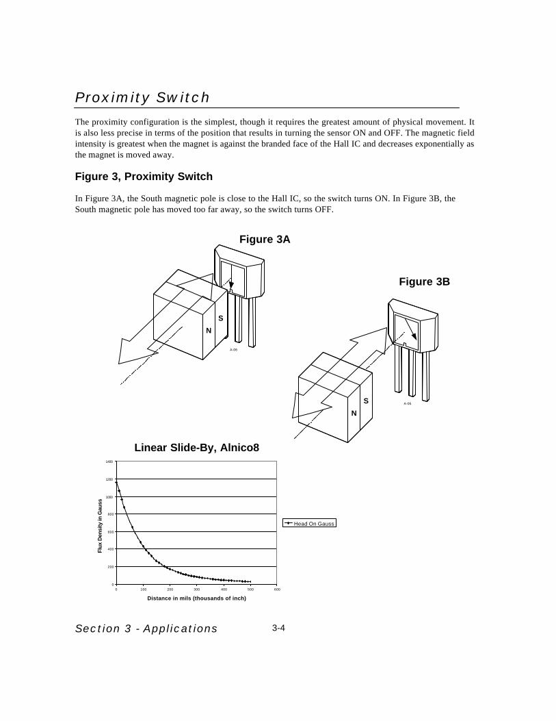
Proximity SwitchThe proximity configuration is the simplest, though it requires the greatest amount of physical movement. Itis also less precise in terms of the position that results in turning the sensor ON and OFF. The magnetic fieldintensity is greatest when the magnet is against the branded face of the Hall IC and decreases exponentially asthe magnet is moved away.
Figure 3, Proximity Switch
In Figure 3A, the South magnetic pole is close to the Hall IC, so the switch turns ON. In Figure 3B, theSouth magnetic pole has moved too far away, so the switch turns OFF.
Section 3 - Applications 3-4
0
200
400
600
800
1000
1200
1400
0 100 200 300 400 500 600
Distance in mils (thousands of inch)
Flux
Den
sity
in G
auss
Head On Gauss
S
NA-05
S
N
A-06
Figure 3A
Figure 3B
Linear Slide-By, Alnico8

An invisible or sealed switch may be made with either configuration. The Hall IC may be inside a sealedcontainer to shield it from oil or water, while the magnetic field penetrates or “sees” through the sealedenclosure. Refer to Figure 4.
Figure 4, Sealed Box
The Hall IC can be shielded from the elements and remain sensitive to magnetic fields.
Interrupt SwitchWhen the Hall IC and magnet are fixed, the Hall IC can be activated using a ferrous vane. This system,composed of a Hall IC, magnet and ferrous vane is called an interrupt switch. In the interrupt switch themagnet is positioned so the South pole turns ON the switch while the Hall IC and magnet positions arefixed relative to each other. When a vane made of a ferrous material is placed between the magnet andHall IC, the magnetic field is shunted or reduced to a very small fraction of the maximum field, turningthe switch OFF. This vane is shown in Figure 5 as a notched interrupter. This switch is an effective wayto sense position.
Figure 5, Interrupt Switch
In Figure 5A, the South magnetic pole is exposed to the Hall IC through the vane, so the switch turnsON. In figure 5B, the switch turns OFF because the magnetic field is blocked by ferrous material.
Section 3 - Applications3-5
S
N
A-07
S
N
A-08
S
N
A-09
Figure 5A Figure 5B

Rotary Interrupt SwitchThe interrupt switch can be incorporated in applications of speed or position sensing, generally of rotat-ing objects. The Rotary Interrupt Switch, in Figure 6, uses a toothed ring to interrupt the magnetic fieldreaching the Hall IC. When a solid piece of steel (ferrous vane) blocks the magnetic field, the switch turnsOFF. During the gaps, or spaces in the steel, the South magnetic pole turns ON the switch. This is the sys-tem commonly used for automotive ignition and many industrial applications, where accurate position iscritical.
Figure 6, Rotary Interrupt Switch
Figure 6 uses a notched interrupter on a rotating shaft to activate the device.
Section 3 - Applications 3-6
S
N
A-10
Figure 6

Rotary Slide-by SwitchFigure 7, Rotary Slide-by Switch
The Rotary Slide-by Switch in Figure 7 is generally used to measure rotary speed to synchronize switch-ing with position. The Hall IC is activated by a rotating magnet. When the South pole passes by the HallIC, the IC is switched ON. As the North pole passes, the Hall IC is switched OFF. The solid circular mag-net, shown in Figure 7A, is called a Ring Magnet. A ring magnet has alternating North and South poles.Ring magnets may have from two poles to thirty-six or more, depending on size. Graph 1, below illus-trates the transition between North and South polarity at various air gaps. Notice the transition point issimilar at the various gaps.
Graph 1, Rotary Slide-by vs. Air gap
Section 3 - Applications3-7
S NSN
A-11
NS
A-12
Figure 7A
6 Pole Ring Magnet
-150
-100
-50
0
50
100
150
0 50 100 150 200 250 300 350 400
Rotation in Degrees
Flux
Den
sity
in G
auss
0 Airgap0.025" airgap0.050" Airgap0.100" Airgap0.150" airgap
Figure 7B
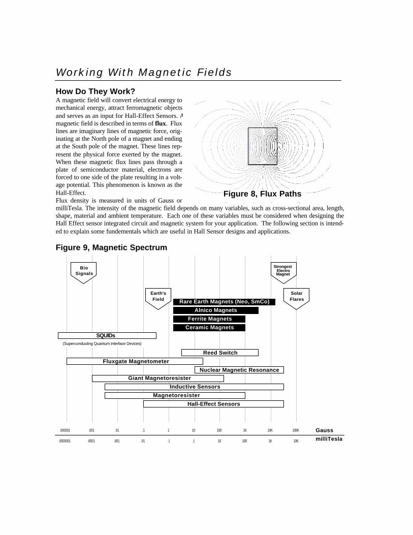
Working With Magnetic FieldsHow Do They Work?A magnetic field will convert electrical energy tomechanical energy, attract ferromagnetic objectsand serves as an input for Hall-Effect Sensors. Amagnetic field is described in terms of flux. Fluxlines are imaginary lines of magnetic force, orig-inating at the North pole of a magnet and endingat the South pole of the magnet. These lines rep-resent the physical force exerted by the magnet.When these magnetic flux lines pass through aplate of semiconductor material, electrons areforced to one side of the plate resulting in a volt-age potential. This phenomenon is known as theHall-Effect.Flux density is measured in units of Gauss ormilliTesla. The intensity of the magnetic field depends on many variables, such as cross-sectional area, length,shape, material and ambient temperature. Each one of these variables must be considered when designing theHall Effect sensor integrated circuit and magnetic system for your application. The following section is intend-ed to explain some fundementals which are useful in Hall Sensor designs and applications.
Figure 9, Magnetic Spectrum
N
S
Figure 8, Flux Paths
Hall-Effect Sensors
Magnetoresister
Inductive Sensors
Giant MagnetoresisterNuclear Magnetic Resonance
Fluxgate Magnetometer
Reed Switch
(Superconducting Quantum Interface Devices)
Ferrite Magnets
Alnico Magnets
Rare Earth Magnets (Neo, SmCo)
Ceramic Magnets
.000001 .001 .01 .1 1 10 100 1K 10K 100K Gauss
10K1K100101.1.01.001.0001.0000001 milliTesla
BioSignals
Earth'sField
StrongestElectroMagnet
SolarFlares
SQUIDs

Evolution of MagneticsModern society would not exist in its present form if not for the development of permanent magnet technology.Many of the major advances in the last century can be traced to the development of yet better grades of magnetmaterials. The earliest magnets were naturally occurring iron ore chunks mostly originating in Magnesia hencethe name magnes. We now know these materials to be Fe3O4, a form of magnetite. Their unique properties wereconsidered to be supernatural. Compasses based on these magnes were called lodestones after the lodestar orguidestar. They were highly prized by the early sailing captains.
The PioneersMore sophisticated magnets did not come into use until the 15th century when William Gilbert made scientificstudies of magnets and published the results. He found that heating iron bars and allowing them to cool whilealigned to the earth's field would create a stronger magnet than a naturally occurring lodestone. His magnet tech-nology however remained a curiosity until the 19th century when Hans Christian Oersted developed the ideathat electricity and magnetism were related. He was the first to determine that magnetic fields surround a currentcarrying wire. It would require the development of atomic particle theories before scientific explanations of per-manent magnets made further advances. The practical applications for magnets continued throughout the 19thcentury.Magnetism in a solid object seems to defy rational explanation. The magnetism is developed in a manner simi-lar to electrons moving through a coil of wire, magnetic fields are created by electrons in motion around the atom-ic nucleus. This nuclear model of an atom with electrons spinning in orbit around a nucleus provides a source ofcharges in motion. In most materials however, the number of electrons moving in one direction equals that mov-ing oppositely and hence their magnet fields cancel. This results in no overall magnetic field for the material. Ittakes many electrons spinning in the same direction to generate a measurable field. Unfortunately there are kinet-ic forces at work causing atoms to constantly vibrate and rotate resulting in random alignment. The higher thetemperature the more kinetic energy and the more difficult it is to maintain alignment. Fortunately soldsme mate-rials exhibit an electrostatic property known as exchange interaction which serves to maintain parallel alignmentof groups of atoms. This force only works over short distances amounting to a few million billion atoms. Thismay sound like a large quantity but on an atomic scale it is a relatively small amount. These groups are knownas dipoles and are the fundamental building blocks that determine the properties and behavior of permanent mag-net.
Relative Magnetic PropertiesMagnets and magnetic materials are classified by many terms which describe many different properties, someof which are explained and used in this book. Perhaps the most commonly asked question about a magnet is“How strong is it?” Although this can lead to a complex explanation, Figure 9 is an excellent guide to the rela-tive strength of magnetic forces, from strongest magnetic forces known such as solar flares to the nearly unde-tectable magnetic signals passing through the neuro network of our bodies.
The Hysteresis CurveA solid block of magnetic material is composed of multiple dipoles wherein the alignment of all of the dipolesresults in a constant field of maximum value. This maximum field attainable is known as the saturation field. Thiscondition is obtained by placing a sample of material in a sufficiently strong electromagnetic field and increas-ing the electric current through the magnetizing coil. As the samples dipoles begin to align a function for the rela-tionship between the magnetizing field and the field in the sample becomes apparent. In the low field levels theslope of the curve is very steep. This relates to the rapid alignment with the magnetizing field of a majority of dipoles. As current levels increase

linearly the number of dipoles aligning decreases. The result is a shallow slope to the function curve. At somepoint, related to the material properties, increases in current through the magnetizing coil will not increase thevalue of the field in the magnet. This is the saturation value for the material. When the external magnetizingfield is removed the magnetic field value of the sample "relaxes" to a steady state known as the Br value, or resid-ual flux value.An analogy to charging a battery is appropriate. At some level the battery is fully charged and will not acceptany more energy. It is an amazing thing however that the magnet will never lose its charge unless it is subjectedto a larger field of opposite polarity, or if the temperature is raised above the point known as the CurieTemperature. This temperature varies depending on the material and is specified in all manufacturers datasheets.In summary we have discussed two of the three forces at work, one the magnetizing force measured in oerstedswith cgs units or ampere turns/meter in the SI system. The second is the resultant or induced field in the sample,this is measured with gauss in cgs units and Teslas in the SI system (see Tables 1 and 2, below).
Table 1, Magnetic Units Comparison
Table 2, Magnetic Units Conversion
The third is reluctance or its' reciprocal permeability, think of this as the magnetic resistance per unit volume ofthe sample being magnetized. Now that we have a magnetized magnet we can consider what occurs when forcesact to de-magnetize it. If we reverse the direction of current flow in the magnetizing coil a negative field is cre-ated. As the negative current is increased the dipole alignment is reversed or undone. A curve results which issimilar to the magnetizing curve but in mirror image form. When the samples' flux value is completely demag-netized the demagnetizing force at that instant is the coercive force -HC. This force is also measured like themagnetizing force in Oersteds. Increasing the negative current level in the magnetizing coil.
Unit Symbol cgs System SI System English System
Flux Φ Maxwell weber Maxwell
Flux Density B Gauss Tesla lines/in2
Magnetizing Force H Oersted ampere turns/m ampere turns/in
Multiply By To obtain
lines/in2 0.155 Gauss
lines/in2 1.55 x 10⁻⁵ Tesla
Gauss 6.45 lines/in2
Gauss 10-4 Tesla
Oersteds 79.577 Ampere turns/m
Ampere turns/in 0.495 Oersteds
Ampere turns/in 39.37 Ampere turns/m

This brings us once again to Br or the residual flux value, the pole orientation is now opposite the first satura-tion state. Finally reversing the current back to its original direction we can exercise the sample through the curveonce more and pass through the +HC value to arrive once again at the Br value. We have now completed the hys-teresis loop for the material and can draw a curve relating B to H as shown in figure "y".
Figure 10, Hysteresis Loop
This curve is fundamental to characterizing and comparing classes and grades of magnetic materials.An important aspect of magnetic materials behavior is dependent on the physical arrangement of the magnet inthe application. In a motor the permanent magnet is operating in a magnetic circuit with mostly low reluctancepaths for the field to circulate through. In many sensor applications however the magnet operates with little orno magnetic circuit. This operating condition is known as open loop operation.
B
H
Before magnetic force is applied (current),domains are randomly oriented and noenergy is created.
BS
0
When magnetic force is applied, domainsbecome oriented in the direction of theapplied field.
A
BS
0
When magnetic force (current) is removed,domains don't completely randomize,therefor retaining some of the energy.
A
Br
B+
0
When magnetic force (current) is reversed,and released, the inverse of the aboveoccurs, creating the complete hysteresisloop.The hysteresis loop is unique to all magneticmaterials. This diagram does not illustrateany specific material or magnetic circuit
A
Br
B-
H+H-
Br
Hc
Hc
Br = residual inductanceHc = coercive force
A magnet in a closed high permeability magnetic circuit (an iron bar connecting the north to the south pole)will operate at or near the Br value. A magnet with no pole pieces will operate with a flux density down thedemagnetization curve from the Br value, how far down is dependant on the aspect ratio or the ratio of thelength to the diameter. Short wide magnets will generate lower flux than tall skinny magnets of the same vol-ume.The concept of the load line and the operating point on the demagnetization curve will influence many magnet-ic parameters. These include the flux density available to actuate a sensor and the reversible temperature coeffi-cient.
Temperature EffectsGraphical representations are often used to determine the operating point on the demagnetization curve.Temperature effects on permanent magnets are dependent on the type of material considered. Manufacturers willspecify various figures of merit to describe the temperature performance of magnet materials. Among these arethe Reversible losses that are represented by Tc. The term refers to the losses in the Br and the Hc. A calcula-tion can show that for every incremental change in temperature the magnet will lose a proportion of its strength.This loss will be recovered completely so long as the temperature does not exceed the Tmax or maximum prac-tical operating temperature in air. The Tmax value is dependent on the magnets operating point on the demag-netization curve. A magnet operating closer to Br can have a higher Tmax. Irreversible losses are described aslosses that can only be recovered by re-magnetizing the sample to saturation with an electromagnetic field. Theselosses occur when the operating point falls below the "knee" on the demagnetization curve. This can occur dueto temperature and inefficient magnetic circuit design. An important feature of magnet materials is the Curie tem-perature, TCurie,. This is a temperature at which the metallurgical properties of the sample are adversely effected. In most applications the ambient temperature can never approach the Curie temperature without completelydestroying the electronic components first.
Losses Over TimeTime has minimal effect on the strength of permanent magnets. Long term studies in the industry have shownthat at 100,000 hours the losses for Rare Earth Samarium Cobalt magnets were essentially zero and for Alnico5 were less than 3%. In the case of Rare Earth Neodymium materials the losses are compounded by internal cor-rosion.
Corrosion & CoatingsIt is often necessary to provide coatings to these materials to minimize the corrosion that results from the Ironcontent. We lay-people refer to this stuff as rust. The options for coatings include epoxies, zinc and nickel. Thebest of these is nickel however it is slightly magnetic and marginally reduces the available field. Coatings canalso be useful with Rare Earth Samarium to minimize "spalling" or the fracture of tiny slivers from the cornersof this brittle, hard material.In many sensor applications these characteristics are of little significance but as with all engineering tasks it isup to the design engineer to know what can safely be ignored and what must be consider for the projects suc-cess.Many texts are available to aid in a complete understanding of magnets. The Magnetic Material ProducersAssociation is a trade group that establishes and maintains standards for basic grades and classes of materials.Their reference booklets are an excellent source for detailed technical data on the various generic classes of materials. Certain manufacturers also provide excellent databooks with helpful applications and design sections.These include Arnold Engineering Company, Magnet Sales & Manufacturing, Magnetfabrik Schramberg,Hitachi Metals; Magnetic Materials Division and Widia Magnettechnik.
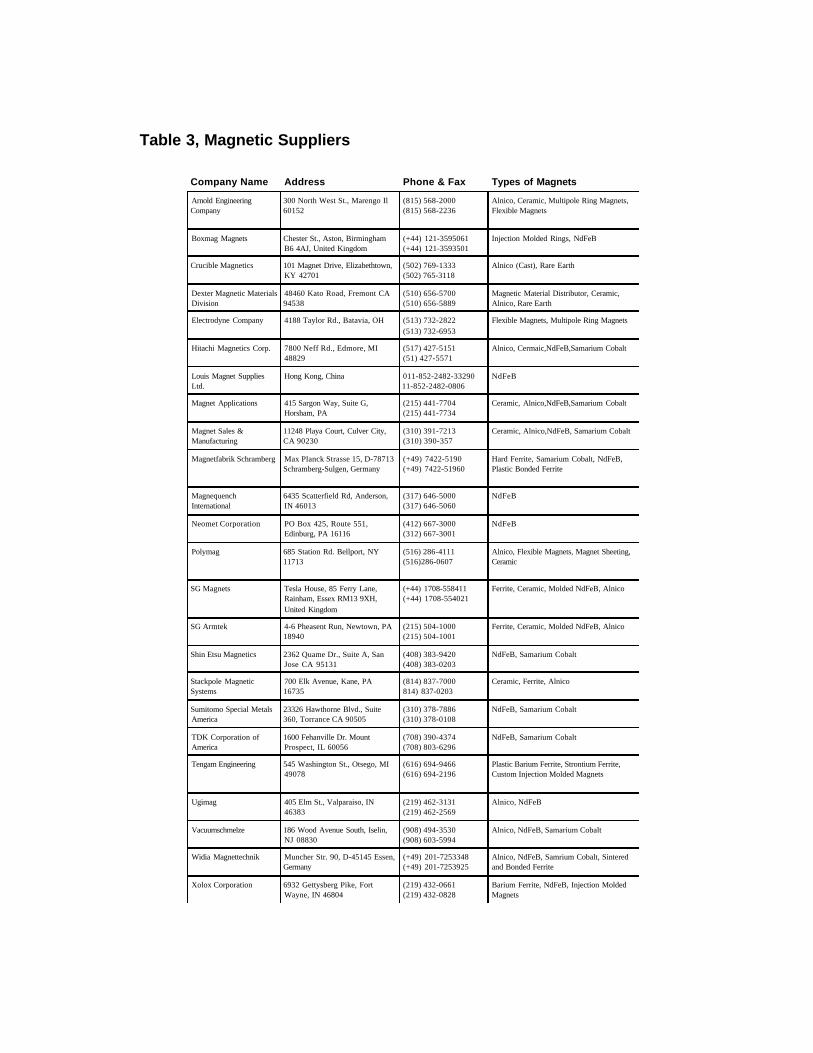
Table 3, Magnetic Suppliers
Company Name Address Phone & Fax Types of Magnets
Arnold EngineeringCompany
300 North West St., Marengo Il60152
(815) 568-2000(815) 568-2236
Alnico, Ceramic, Multipole Ring Magnets,Flexible Magnets
Boxmag Magnets Chester St., Aston, BirminghamB6 4AJ, United Kingdom
(+44) 121-3595061(+44) 121-3593501
Injection Molded Rings, NdFeB
Crucible Magnetics 101 Magnet Drive, Elizabethtown,KY 42701
(502) 769-1333(502) 765-3118
Alnico (Cast), Rare Earth
Dexter Magnetic MaterialsDivision
48460 Kato Road, Fremont CA94538
(510) 656-5700(510) 656-5889
Magnetic Material Distributor, Ceramic,Alnico, Rare Earth
Electrodyne Company 4188 Taylor Rd., Batavia, OH (513) 732-2822(513) 732-6953
Flexible Magnets, Multipole Ring Magnets
Hitachi Magnetics Corp. 7800 Neff Rd., Edmore, MI48829
(517) 427-5151(51) 427-5571
Alnico, Cermaic,NdFeB,Samarium Cobalt
Louis Magnet SuppliesLtd.
Hong Kong, China 011-852-2482-3329011-852-2482-0806
NdFeB
Magnet Applications 415 Sargon Way, Suite G,Horsham, PA
(215) 441-7704(215) 441-7734
Ceramic, Alnico,NdFeB,Samarium Cobalt
Magnet Sales &Manufacturing
11248 Playa Court, Culver City,CA 90230
(310) 391-7213(310) 390-357
Ceramic, Alnico,NdFeB, Samarium Cobalt
Magnetfabrik Schramberg Max Planck Strasse 15, D-78713Schramberg-Sulgen, Germany
(+49) 7422-5190(+49) 7422-51960
Hard Ferrite, Samarium Cobalt, NdFeB,Plastic Bonded Ferrite
MagnequenchInternational
6435 Scatterfield Rd, Anderson,IN 46013
(317) 646-5000(317) 646-5060
NdFeB
Neomet Corporation PO Box 425, Route 551,Edinburg, PA 16116
(412) 667-3000(312) 667-3001
NdFeB
Polymag 685 Station Rd. Bellport, NY11713
(516) 286-4111(516)286-0607
Alnico, Flexible Magnets, Magnet Sheeting,Ceramic
SG Magnets Tesla House, 85 Ferry Lane,Rainham, Essex RM13 9XH,United Kingdom
(+44) 1708-558411(+44) 1708-554021
Ferrite, Ceramic, Molded NdFeB, Alnico
SG Armtek 4-6 Pheasent Run, Newtown, PA18940
(215) 504-1000(215) 504-1001
Ferrite, Ceramic, Molded NdFeB, Alnico
Shin Etsu Magnetics 2362 Quame Dr., Suite A, SanJose CA 95131
(408) 383-9420(408) 383-0203
NdFeB, Samarium Cobalt
Stackpole MagneticSystems
700 Elk Avenue, Kane, PA16735
(814) 837-7000814) 837-0203
Ceramic, Ferrite, Alnico
Sumitomo Special MetalsAmerica
23326 Hawthorne Blvd., Suite360, Torrance CA 90505
(310) 378-7886(310) 378-0108
NdFeB, Samarium Cobalt
TDK Corporation ofAmerica
1600 Fehanville Dr. MountProspect, IL 60056
(708) 390-4374(708) 803-6296
NdFeB, Samarium Cobalt
Tengam Engineering 545 Washington St., Otsego, MI49078
(616) 694-9466(616) 694-2196
Plastic Barium Ferrite, Strontium Ferrite,Custom Injection Molded Magnets
Ugimag 405 Elm St., Valparaiso, IN46383
(219) 462-3131(219) 462-2569
Alnico, NdFeB
Vacuumschmelze 186 Wood Avenue South, Iselin,NJ 08830
(908) 494-3530(908) 603-5994
Alnico, NdFeB, Samarium Cobalt
Widia Magnettechnik Muncher Str. 90, D-45145 Essen,Germany
(+49) 201-7253348(+49) 201-7253925
Alnico, NdFeB, Samrium Cobalt, Sinteredand Bonded Ferrite
Xolox Corporation 6932 Gettysberg Pike, FortWayne, IN 46804
(219) 432-0661(219) 432-0828
Barium Ferrite, NdFeB, Injection MoldedMagnets
Section 3 - Applications 3-8
Choosing A Magnet
Common Magnetic MaterialsThere are four classes of commercial permanent magnet materials. They are:CeramicAlnicoNeodymium Iron BoronSamarium Cobalt
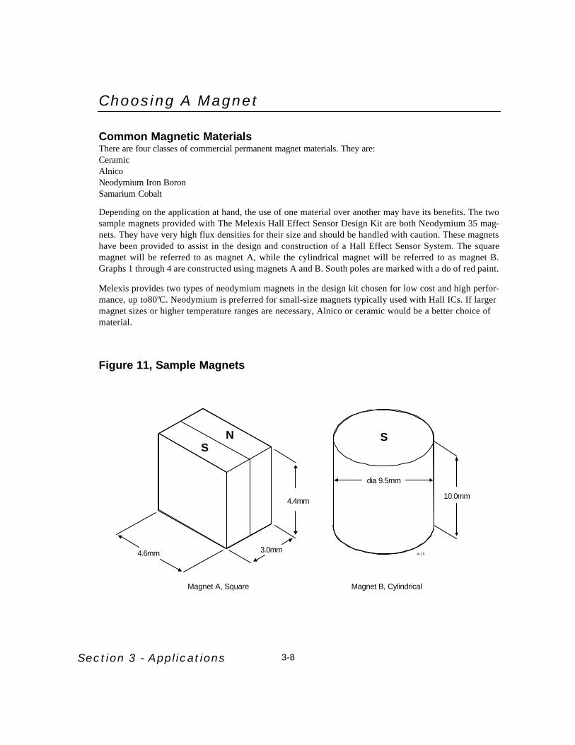
Depending on the application at hand, the use of one material over another may have its benefits. The twosample magnets provided with The Melexis Hall Effect Sensor Design Kit are both Neodymium 35 mag-nets. They have very high flux densities for their size and should be handled with caution. These magnetshave been provided to assist in the design and construction of a Hall Effect Sensor System. The squaremagnet will be referred to as magnet A, while the cylindrical magnet will be referred to as magnet B.Graphs 1 through 4 are constructed using magnets A and B. South poles are marked with a do of red paint.
Melexis provides two types of neodymium magnets in the design kit chosen for low cost and high perfor-mance, up to800C. Neodymium is preferred for small-size magnets typically used with Hall ICs. If largermagnet sizes or higher temperature ranges are necessary, Alnico or ceramic would be a better choice ofmaterial.
Figure 11, Sample Magnets
4.4mm
3.0mm4.6mm
NS
Magnet A, Square Magnet B, Cylindrical
dia 9.5mm
10.0mm
S
A-15

Section 3 - Applications 3-10
Rare-Earth Magnets
Neodymium Iron Boron
Attributes of NeodymiumLow cost
Very high resistance to demagnetization
High energy for sizeGood in ambient temperature
Material is corrosive and should be coated for long-term maximum energy output
Low working temperature
Applications of NeodymiumMagnetic separatorsLinear actuators
Servo motors
DC motors (automotive starters)Computer rigid disk drives
Samarium Cobalt
Attributes of SamariumHigh resistance to demagnetization
High energy (magnetic strength is strong for its siz
Good temperature stabilityExpensive material
Applications of SamariumComputer disk drives
Automotive high-temperature environments
Traveling-wave tubesLinear actuators
Satellite systems

Alnico Magnets
Attributes of Both Cast and Sintered Alnico (Large Magnets)Very stable, great for high temperature applications
Maximum working temperature 5240C to 5490C
May be ground to size
Does not lend itself to conventional machining (hard & brittle)
High residual induction and energy product, compared to ceramic material
Low coercive force, compared to ceramic and rare-earth materials (more subject to demagnetization)
Most common grades of Alnico are 5 & 8
Applications of Alnico MagnetsMagnetos Security systems
Coin acceptors Clutches and bearings
Distributors Microphones
DC motors
Ceramic Magnets
Attributes of Ceramic MagnetsHigh intrinsic coercive force
Tooling is expensive
Least expensive material, compared to Akbuci and rare-earth magnets
Limited to simple shapes, due to manufacturing process
Lower service temperature than Alnico,.greater than rare-earth magnets
Finishing requires diamond cutting or grinding wheel
Lower energy product than Alnico and rare-earth magnets
Most common grades of ceramic are 5 & 8 (1-8 possible)
Grade 8 is the strongest ceramic material available
Applications of Ceramic MagnetsSpeaker magnets
DC brushless motors
Magnetic Resonance Imaging (MRI)
Magnetos used on lawnmowers and outboard motors
DC permanent-magnet motors (used in cars)
Separators (separate ferrous material from nonferrous)
Used in magnetic assemblies designed for lifting, holding, retrieving and separating
Section 3 - Applications3-11

Section 3 - Applications 3-12
Table 4, Magnetic Characteristics
Magnetic Material Density MaximumEnergyProductBH(max)
Br ReversibleCoefficient
ResidualInduction
Br
CoerciveForce
Hc
IntrinsicCoerciveForce Hci
MaximumOperating
Temperature
CurieTemperature
lbs/in3 g/cm3 MGO %/oC Gauss Oersteds Oersteds oF oC oF oC
SmCo 18 0.296 8.2 18.0 -0.04 8700 8000 20000 482 250 1382 750
SmCo 20 0.296 8.2 20.0 -0.035 9000 8500 15000 482 250 1382 750
SmCo 24 0.304 8.4 24.0 -0.035 10200 9200 18000 572 300 1517 825
SmCo 26 0.304 8.4 26.0 -0.035 10500 9000 11000 572 300 1517 825
Neodymium 27 0.267 7.4 27.0 -0.12 10800 9300 11000 176 80 536 280
Neodymium 27H 0.267 7.4 27.0 -0.12 10800 9800 17000 212 100 572 300
Neodymium 30 0.267 7.4 30.0 -0.12 11000 10000 18000 176 80 536 280
Neodymium 30H 0.267 7.4 30.0 -0.12 11000 10500 17000 212 100 572 300
Neodymium 35 0.267 7.4 35.0 -0.12 12300 10500 12000 176 90 536 280
Alnico 5 (cast) 0.264 7.3 5.5 -0.02 12800 640 640 975 525 1580 860
Alnico 8 (cast) 0.262 7.3 5.3 -0.025 8200 1650 1860 1020 550 1580 860
Alnico 5 (sintered) 0.250 6.9 3.9 -0.02 10900 620 630 975 525 1580 860
Alnico 8 (sintered) 0.252 7.0 4.0 -0.025 7400 1500 1690 1020 550 1580 860
Ceramic 1 0.177 4.9 1.05 -0.20 2300 1860 3250 842 450 842 450
Ceramic 5 0.177 4.9 3.4 -0.20 3800 2400 2500 842 450 842 450
Ceramic 8 0.177 4.9 3.5 -0.20 3850 2950 3050 842 450 842 450

Section 3 - Applications 3-28
Magnetic Design
Input CharacteristicsDigital Hall-Effect Sensors have specific magnetic response characteristics that govern their actuationfrom OFF to ON. These characteristics are classified in terms of operate point, release point and differ-ential. The operate point, commonly referred to as BOP, is the point at which the magnetic flux densityturns the Hall Sensor ON, allowing current to flow from the output to ground. Conversely, the releasepoint, commonly referred to as BRP, is the point at which the magnetic flux density turns the Hall SensorOFF. The absolute difference between BOP and BRP is referred to as Hysteresis, Bhys. The purpose ofhysteresis is to eliminate false triggering, which can be caused by minor variations in input, electricalnoise and mechanical vibration. There are three basic types of Digital Hall Sensors commonly used, aslisted below:
Switch - (unipolar) Operates with a single magnetic pole. Guaranteed not to latch ON in the absence of a magnetic field. Opposing field has no effect. Generally used for mechanical switch replace ment.
Latch - (bipolar) responds to both magnetic poles. Turns on in the presence of North or south pole, andturns off only when the opposing field is sufficiently strong. Guaranteed to latch. Used primaryily in brushless DC motor applications.
Bipolar Switch - (unipolar or bipolar) described as a device which responds to the zero-crossing fromNorth to South poles
The Hall-Effect LatchThe latch is a type of Hall IC which remains in either state (output ON or Off) until an opposite pole mag-net is applied. A South magnetic pole turns the device ON (BOP). The device will stay ON until a Northmagnetic pole is applied and turns it OFF (BRP). Melexis manufactures two types of Hall Effect latches.designated for .2.2V to 18V operation. The US2880 series of Hall Effect Latches are designed for highsensitivity. For more information refer to the data sheet section of this manual.
The Hall Effect SwitchThere are two types of Hall Effect Switches, unipolar. The unipolar switch is normally “OFF” in theabsence of a magnetic field. The device turns ON (BOP) in the presence of a sufficiently strong Southmagnetic pole, and turns OFF BRP) in the presence of a weaker South magnetic pole. MELEXIS manu-factures the US5881UA and US5881SO Hall Effect Switches. For more information refer to the data sheetsection of this manual.
Magnetic Design ConsiderationsWhen designing a magnetic circuit, there are five considerations to be covered:
1. Cost of Hall IC, Magnet and Assembly2. Temperature Range3. Position Tolerance of Assembled Parts4. Position Switching Accuracy5. Tolerance Buildup

3-29
CostHall IC cost will vary depending on the temperature specifications of BOP, BRP and Bhys. A looselyspecified device may easily be one half to one third the cost of a tightly specified device, yet perform thesame job. By providing steep slopes of flux density vs. distance and using strong magnets, the Hall ICcost may be reduced.
Temperature RangeHall Effect Sensors are categorized into different temperature ranges for the use in application-specificdesign. It is very important that the Hall IC you select complies with your system’s ambient temperature.
Position ToleranceDepending on the application and how it is assembled, the position of components, such as the magnet,Hall IC and mechanical assembly, will determine the mechanical variations of the system. Some systemsare more tolerant of changes in air gap and lateral motion than others.
Position Switching AccuracyThe requirement in angular (degree) or linear position ultimately governs the magnetic circuit and HallIC specifications. That is if switching must repeat +0.1250in. or +0.1mm then the Hall IC specificationwill be much tighter than if the specification is +1.00 or +1.0mm.
Tolerance BuildupTolerance buildup is the sum of all the variables that determine the operate point and release point of aHall IC. These variables include position tolerance,temperature coefficient, wear and aging of the assem-bly and magnet variations.
Total Effective Air GapAs mentioned previously, both Magnet A and Magnet B in the design Kit are composed of the same mate-rial. Although the two magnets have similar characteristics, due to the difference in size and shape total Effective Air Gap (TEAG) will have different effects on each magnets’ flux density vs. distancecurve.
TEAG is defined as the sum of active area depth and the distance between the Hall IC’s branded face tothe surface of the magnet. TEAG = Air Gap + Active Area Depth. Active area depth is simply the dis-tance from the branded face of the sensor to the actual Hall Cell within it. The TEAG should be as smallas the physical system will allow, after taking into consideration factors such as the change in air gap withtemperature due to mounting, vane or interrupt thickness and wear on mounting brackets.
Graph 2 is given to show the effects of air gap on the slope of a graph using a single-pole slide-by con-figuration with magnet A.
Section 3 - Applications

Section 3 - Applications 3-30
Graph 2, Slide-by Method with Magnet A Steep Slope vs. Shallow Slope
Tolerances Build-upThe following examples incorporate many different factors in order to show how tolerance buildup canaffect a Hall Effect system. Air gap tolerance, temperature range, and the temperature coefficient of themagnet will cause the activation distance of a US5881 EUA to vary, thus impacting switching accuracy.
Tolerances:
Air gap Tolerance = 3mm. +1 mm. and 6mm. +1mm.US5881EUA BOP/BRP Range = 95G min. BRP to 300G max. BOP(IC Temperature Selection (EUA) = -40oC to 85oC)Temperature Range = -40 oC to 85oCMagnet Temp. Coefficient = -0.1098%/oC
The US5880 Hall-Effect Switch has a maximum BOP of 250 Gauss and a minimum BRP of 140 Gauss.If this part were to be actuated by sample Magnet B at an air gap of 3mm and 6mm, the following resultswould occur (See Graphs 3 and 4). Each graph has an air gap tolerance of +1mm which could be due toa loosely fitted mechanical assembly. Notice the difference in distance and slope between Graphs 3 and4.
Graph 3, Slide-by With Magnet A, Shallow Slope
Graph 2 shows what happens to the slope of a flux density vs. distance graph by using different air gaps with the same magnet configuration.
Distance (mm) 1 2 3 4 5 6 7 8 9 10
400
200
0
Flux
Den
sity
(Gau
ss)
600
800
1000
1200
Air Gap = 2.5mmAir Gap = 5mm
0
200
400
600
800
1000
0 2 4 6 8 10 12 14 16 18 20
Distance (mm)
Flux
Den
sity
(Gau
ss)
Air Gap = 5 mmAir Gap = 6 mmAir Gap = 7 mm
Always "OFF"
Always "ON"

3-31
Graph 4, Slide-by With Magnet B, Steep SlopeThe effects of mechanical tolerance on a Hall Effect System have just been illustrated. Temperature rangecan also affect this system. Temperature will expand or contract the mechanical assembly, but will alsoaffect the field strength of the magnet and the distance from BOP t BRP of the Hall IC. The Neodymiumsample magnets used in this kit have a temperature coefficient of -).1098%/0C. This means that as tem-perature increases by one degree Celsius, the Flux Density will decrease by 0.1098%.
Graph 5, Effects of Temperature on Flux Density
Due to the temperature coefficient, the magnet will have a difference in flux density of 30% and a changein activation distance of 1mm over this range of temperature. This may not appear tobe a significant dif-ference in field strength or distance, but in conjunction with other mechanical factors, temperature couldbecome a factor.
Design Example 2: Now that Design Example 1 illustrated the effects of mechanical, magnetic and HallIC tolerances within a Hall Effect System. Design Example 2 illustrates how they produce tolerancebuildup.
Tolerances:
Air Gap Tolerance = 2mm +0.5mmUS5881EUA BOP/BRP Range = 90G min. BRP to 300G max. BOP(IC Temperature Selection (EUA) = -40oC to 85oC)Temperature Range =-40oC to 85oCMagnet Temp. Coefficient = -0.1098%/oC
Section 3 - Applications
0
100
200
300
400
500
600
0 2 4 6 8 10 12
Distance (mm)
Flux
Den
sity
(Gau
ss)
Air Gap = 2 mmAir Gap = 3 mmAir Gap = 4 mm
Always "ON"
Always "OFF"
Always "ON"
Always "OFF"
0
100
200
300
400
500
600
700
0 5 10 15 20Distance mm
Flux
Den
sity
(Gau
ss)
Flux Denisity @ 25C
Flux Denisity @ -40C
Flux Denisity @ 85C

Section 3 - Applications 3-32
Sample Magnet A is used in the double-pole slide-by method to show the variation air gap may have ina mechanical system. These changes in air gap may be caused by factors such as vibration, wear, etc...Note the differences in each air gap’s slope and maximum flux density. As the air gap distance becomeslarger, a decrease in flux density slope will cause less accurate switching in a Hall Effect System.Graph 9
Graph 6, Slide-by with Sample Magnet A Air Gap Tolerance
By zooming in on the previous graph, min. BRP and max. BOP of the Hall Effect System can be shownin greater detail and will also reveal the differences in activation distance at each air gap. See Graph 10.
Graph 7, Slide-by with Sample Magnet AChange in Activation Distance with Air Gap
The plotted lines in Graph 7 do not include the effects of temperature. Graph 8 shows how temperaturewill change the magnet’s flux density characteristics over the selected operating temperature range (-400Cto 850C), thus affecting the activation distance at min. BRP and max. BOP. To simplify the graph, onlythe 2mm air gap is plotted.
-1200-1000
-800-600-400-200
0200400600800
10001200
-30 -25 -20 -15 -10 -5 0 5 10 15 20 25 30
Distance (mm)
Flux
Den
sity
(Gau
ss)
Air Gap = 1.5 mmAir Gap = 2.0 mmAir Gap = 2.5 mm
-400
-300-200
-100
0
100
200
300
400
-1.5 -1 -0.5 0 0.5 1 1.5
Distance (mm)
Flux
Den
sity
(Gau
ss)
Air Gap = 1.5mm
Air Gap = 2.0mm
Air Gap = 2.5mm
Always ON
Always OFF

3-33
Graph 8, Slide-by with Magnet A Change in Activation Distance With TC
There is a 17% difference in flux density over the entire temperature range compared with the fixed-tem-perature case in Graph 7. Note that because of the negative temperature coefficient of the magnet, the neg-ative temperature (-400C) adds flux density to the magnet, while the positive temperature (850C) reducesflux density.
Graph 9 shows how the air gap tolerance and temperature coefficient add together and cause tolerancebuildup in the Hall Effect system.
Graph 9, Slide-by Method with Magnet A Change in Activation distance with Air Gap & TC
The two plotted lines in Graph 9 show the minimum and maximum possible cases when temperature andair gap are considered. The overall difference in distance between min. BRP and max. BOP is slightlylarger because of the sum of tolerances being considered. This design example has shown the tolerancebuildup of air gap, benefits of slope, Hall IC BOP to BRP variations and magnet Tc. We have not con-sidered the variation of initial flux density, which you must obtain from a magnet supplier.
Section 3 - Applications
-400
-300
-200
-100
0
100
200
300
400
-1 -0.75 -0.5 -0.25 0 0.25 0.5 0.75 1
Distance (mm)
Flux
Den
sity
(Gau
ss)
Temp = 25 oCTemp = 85 oC
Temp -40 oC
-400-300-200-100
0100200300400
-1.5 -1 -0.5 0 0.5 1 1.5
Distance (mm)
Flux
Den
sity
(Gau
ss)
A ir Gap = 1.5mm @ -40 oC
Air Gap = 2.5mm @ 80 oC

Section 3 - Applications 3-34
The Push-Pull MethodGraph 10 shows the push-pull method. A South magnetic pole, perpendicular to the branded face, is usedin conjunction with a North magnetic pole at the opposite face. The two magnets in the single-pole slide-by configuration are moved in the X-direction with respect to a stationary Hall IC.
Graph 10, Push-Pull Activation Using Slide-by Method with Magnet AThe Push-Push Method
The push-push method is similar in configuration to push-pull, but requires a South pole located at thebranded face along with a South pole at the opposite side of the Hall IC. When the Hall IC is centeredbetween these two South magnetic poles, their flux density cancels out leaving zero flux density at thisposition. If the two magnets maintain the same distance between each other and are moved in the head-on method in either direction, the flux vs. distance graph will be linear.
Graph 11, Push-Push Activation Using Head-On Mode
The US3881EUA Hall Effect Latch has maximum BOP of 90 Gauss and a minimum BRP of -90Gaussover the temperature range of -400C to 850C. Due to the temperature coefficient of -0.1098%/0C, themagnet will have a difference in flux density of 8% over this distance range. The distance necessary tofully actuate a US3881EUA Hall Effect Latch is approximately 0.35mm from max. BOP to min. BRP.This is an extremely large increase in performance from the previous example.
-200
0
200
400
600
800
1000
1200
1400
-15 -13 -11 -9 -7 -5 -3 -1 1 3 5 7 9 11 13 15
Distance (mm)
Flux
Den
sity
(Gau
ss)
SN
SN
Motion
Air Gap
Motion
Motion
Motion
The Air Gap for both magnets isapproximately 6.3mm
-350-300-250-200-150-100
-500
50100150200250300350
-1 -0.75 -0.5 -0.25 0 0.25 0.5 0.75 1
Distance (mm)
Flux
Den
sity
(Gau
ss)
Temp = 25 oCTemp = -40 oCTemp = 85 oC
Max. Bop
Min. Brp
Gauss BOP BRP Bhys
Maximum 90 -10 100
Minimum 10 -90 100
The Air Gap for both magnets isapproximately 3mm

3-35
Biased OperationBiased operation is a method of controlling the magnetic field surrounding a Hall IC and is quite similarto the Push-Push Method. For example, if a South Pole were attached to the reverse side of a Hall EffectSwitch, the Hall IC would be held on the “OFF” position until a South pole of a larger magnitude is intro-duced to the branded face of the sensor and cancels out the opposing magnetic flux. This can be a veryimportant concept if a Hall IC were located within an electronic system with other opposing magneticfields. It will ensure that the Hall Sensor cannot switch accidentally. Figure 11 is an example of the biasmethod. In Figure 11, the push-button uses a bias magnet to ensure that the button is in the Off positionuntil being pressed. When the button is pressed, the magnet adjacent to the branded face moves in thehead-on configuration closer to the Hall IC. This positive flux density will cancel out the negative fluxdensity provided by the bias magnet, eventually turning the button ON. Once the button is released, thetwo opposing South magnetic fields will repel each other and send the button to its original OFF position.
Figure 11, Push-button with Bias Magnet
If the US5881 Hall Effect Switch were tobe used in this bias magnet configuration, this switch wouldremain in the OFF position until the button ispressed. If the magnet adjacent to the brandedface of the Hall IC has an air gap of 2.0mm beforebeing pressed, the switch will be exposed to a fluxdensity of approximately - 200Gauss. the buttonwill need to be moved a distance of 0.75mminward to exceed 250 Gauss and turn ON. Afterbeing released, the magnets will repel and turnOFF the Hall IC at a distance of 1.7 mm awayfrom the branded face.
Section 3 - Applications
N
SN
S
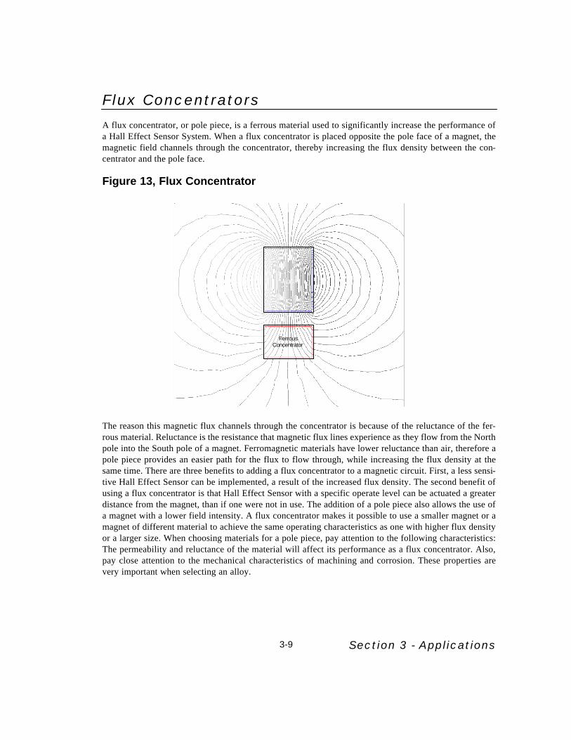
Flux ConcentratorsA flux concentrator, or pole piece, is a ferrous material used to significantly increase the performance ofa Hall Effect Sensor System. When a flux concentrator is placed opposite the pole face of a magnet, themagnetic field channels through the concentrator, thereby increasing the flux density between the con-centrator and the pole face.
Figure 13, Flux Concentrator
The reason this magnetic flux channels through the concentrator is because of the reluctance of the fer-rous material. Reluctance is the resistance that magnetic flux lines experience as they flow from the Northpole into the South pole of a magnet. Ferromagnetic materials have lower reluctance than air, therefore apole piece provides an easier path for the flux to flow through, while increasing the flux density at thesame time. There are three benefits to adding a flux concentrator to a magnetic circuit. First, a less sensi-tive Hall Effect Sensor can be implemented, a result of the increased flux density. The second benefit ofusing a flux concentrator is that Hall Effect Sensor with a specific operate level can be actuated a greaterdistance from the magnet, than if one were not in use. The addition of a pole piece also allows the use ofa magnet with a lower field intensity. A flux concentrator makes it possible to use a smaller magnet or amagnet of different material to achieve the same operating characteristics as one with higher flux densityor a larger size. When choosing materials for a pole piece, pay attention to the following characteristics:The permeability and reluctance of the material will affect its performance as a flux concentrator. Also,pay close attention to the mechanical characteristics of machining and corrosion. These properties arevery important when selecting an alloy.
Section 3 - Applications3-9
N
Magnet
S
FerrousConcentrator

Section 3 - Applications3-13
ElectromagnetsAnother method of actuating Hall Effect Sensors is through the use of electromagnets. They are especial-ly useful in circuit-breaking or current-sensing applications because their magnetism can be “turned on”or “turned off” at will. An electromagnet consists of a coil of wire which may be wrapped around ferrousmaterial or core. The strength of this magnetic field is dependent on many variables, such as the perme-ability of the ferrous material, the number of times the coil is wrapped around the material, the amount ofcurrent flowing through the coil and the length of the core. These variables are related to each other in thesame way for all types of electromagnets, but the formulas differ slightly due to the variance of shape incore material.
Figure 14, Common Electromagnet Shapes
Where:B = magnetic flux densityu0 = permeability of core materialN = number of turns made by coili = amount of current in coilR = mean radius of toroid
Where:B = magnetic flux densityu0 = permeability of core materialN = number of turns made by coili = amount of current in coill = length of cylindrical core
After choosing a core that will physically fit into the proposed current-sensing system, the values of lengthof radius, permeability and at what value the current limiter is to operate will be known. The operate pointand release point for each Melexis Hall IC can be located in the datasheet section of this manual. Byknowing this information, it is now possible to calculate how many turns of wire will be required to pro-duce enough flux density to actuate the Hall Effect Sensor. When designing an electromagnet use mate-rials with the following properties: High saturation induction and high permeability will produce strongmagnetic fields resulting in a smaller device that will operate with little energy. When an electromagnetis being switched on and off, use a material with a low coercive force for faster magnetization and demag-netization. Also pay attention to magnetic aging and mechanical characteristics such as corrosion. This is

Measuring Flux DensityThe Melexis Hall-Effect design kit is supplied with a linear Hal-Effect sensor which has been calibratedto 1mV/G, making it very easy to build a circuit which will measure flux density. This is done with thefully programmable MLX90215, programmed in this case to deliver exactly 2.5V at zero magnetic fieldrising 1mV for every 1 Gauss applied. If a field of 100 Gauss is applied, the output will increase 100mV. Similarly, if a field of -100 Gauss isapplied, the output will decrease 100mV. It is very important to maintain a regulated supply voltage of5V because the output has no internal regulator and is ratiometric. The Hall IC's output is exactly VD D/2,so if the supply voltage changes the output voltage also changes.
Figure 15, Flux Measurement
Figure 9 shows a circuit which allows the Voltmeter to be calibrated to read in units of Gauss. Shifting theground reference of the Voltmeter to exactly the quiescent voltage of the Hall IC makes the 2.5V VOQappear to be zero. The potentiometer allows this to be set to exactly zero. When a magnetic field isapplied, the DVM will display units of Gauss in a range of +/- 2000 Gauss. The resistor network is todivide the output voltage by 10 so it can be measured by200mV meter. If your meter is 2V range, this divider is notused. This circuit can be built into a small case with a batteryand voltage regulator for a very inexpensive flux measuringdevice.
With no divider used:Full Scale: (2.00V) +/-2000 Gauss
+/-200 mT1 Gauss = 1mV1 mT = 0.1mV
With 1/10 divider used:Full Scale: (200mV) +/-2000 Gauss
+/-200 mT1 Gauss = 0.1mV1 mT = 0.01mV
1mT = 10Gauss, exactly
Section 3 - Applications 3-16
MLX902152501000
5V+1%
200ΩPotentiometer
2k
2k
zero adjust
9k*
1k*Attach toVoltmeter
1µF .1µF
A-17
1/10divider
(optional)
Output Voltage vs. Magnetic Flux Density
-200 -100 0 100 200
4.5
4.0
3.5
3.0
2.5
2.0
1.5
1.0
0.5
0.0
5.0O
utpu
t Vol
tage
(Vol
ts)
Flux Density (mT)
MLX902152501000
DVM2.00V Scale
.1µF .1µF
5V
A-16
Figure 16, Flux

Section 3 - Applications3-17
Applications
Balance, Level, Vibration, AccelerationA magnet suspended from a pendulum, free to move in the X - Y plane, may be used to detect level posi-tion, acceleration and vibration. Figure 12 shows a magnet with the center as a North pole and an outerring of South pole. In a level, stable condition, the North pole turns OFF the switch. Motion will causethe magnet to move in such a way that the South pole is over the Hall IC, turning the switch ON.Obviously, the mechanical configuration is not trivial, and will vary greatly depending on the application.Switches like this are used in some washing machines.
Figure 17, Level and Motion Switch
A-18
S N S
S
S
The magnet is free to move relative to the Hall IC.Any force disturbing the magnet may result in a South pole
facing the Hall IC, resulting in an ON condition
Section 3 - Applications 3-18
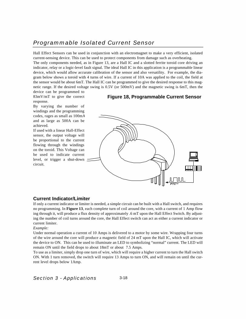
Programmable Isolated Current SensorHall Effect Sensors can be used in conjunction with an electromagnet to make a very efficient, isolatedcurrent-sensing device. This can be used to protect components from damage such as overheating.The only components needed, as in Figure 13, are a Hall IC and a slotted ferrite toroid core driving anindicator, relay or a logic-level fault signal. The ideal Hall IC in this application is a programmable lineardevice, which would allow accurate calibration of the sensor and also versatility. For example, the dia-gram below shows a toroid with 4 turns of wire. If a current of 10A was applied to the coil, the field atthe sensor would be about 6mT. The Hall IC can be programmed to give the desired response to this mag-netic range. If the desired voltage swing is 0.5V (or 500mV) and the magnetic swing is 6mT, then thedevice can be programmed to83mV/mT to give the correctresponse.By varying the number ofwindings and the programmingcodes, rages as small as 100mAand as large as 500A can beachieved.If used with a linear Hall-Effectsensor, the output voltage willbe proportional to the currentflowing through the windingson the toroid. This Voltage canbe used to indicate currentlevel, or trigger a shut-downcircuit.
Current Indicator/LimiterIf only a current indicator or limiter is needed, a simple circuit can be built with a Hall switch, and requiresno programming. In Figure 13, each complete turn of coil around the core, with a current of 1 Amp flow-ing through it, will produce a flux density of approximately .6 mT upon the Hall Effect Switch. By adjust-ing the number of coil turns around the core, the Hall Effect switch can act as either a current indicator orcurrent limiter.Example: Under normal operation a current of 10 Amps is delivered to a motor by some wire. Wrapping four turnsof the wire around the core will produce a magnetic field of 24 mT upon the Hall IC, which will activatethe device to ON. This can be used to illuminate an LED to symbolizing “normal” current. The LED willremain ON until the field drops to about 18mT or about 7.5 Amps.To use as a limiter, simply drop one turn of wire, which will require a higher current to turn the Hall switchON. With 1 turn removed, the switch will require 13 Amps to turn ON, and will remain on until the cur-rent level drops below 1Amp.
PTCTM
Figure 18, Programmable Current Sensor

3-19
Flow MeterOne popular device that uses a Hall IC is a flow meter (Figure 15). The spoked wheel (paddle wheel), isdriven by some type of medium flowing through the pipe. A magnet is attached at the tip of each spoke.In the presence of moving vapor or liquid, the magnets spin at a speed related to the viscosity of the medi-um flowing through the device. The spinning magnets will switch the Hall IC, producing a square waveoutput, with a frequency proportional to the flow rate.
Figure 19, Flow Meter
Liquid or vapor entering in the direction of the arrow spins the paddle wheel switching the Hall IC “ON” and “OFF”, creating a square wave output.
Power Control
Many switches must control significant power. A Hall IC can do this only through a relay or Power FET.For a component cost of $1.00, an isolated 50 Volt, 50 Amp switch can be made.
Figure 20, Power Switch
Section 3 - Applications
SN
U18627
12V Load
Section 3 - Applications 3-20
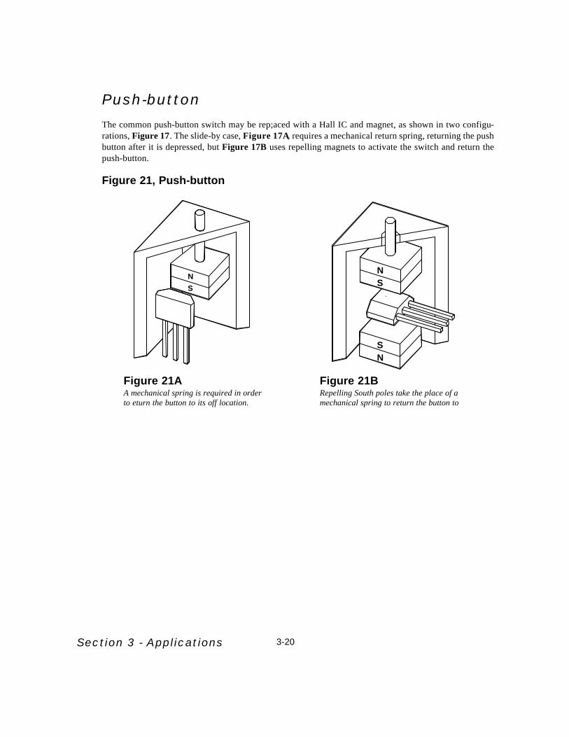
Push-buttonThe common push-button switch may be rep;aced with a Hall IC and magnet, as shown in two configu-rations, Figure 17. The slide-by case, Figure 17A, requires a mechanical return spring, returning the pushbutton after it is depressed, but Figure 17B uses repelling magnets to activate the switch and return thepush-button.
Figure 21, Push-button
N
S
N
SN
S
Figure 21AA mechanical spring is required in orderto eturn the button to its off location.
Figure 21BRepelling South poles take the place of amechanical spring to return the button to

3-21 Section 3 - Applications
Liquid Level Detector/AlarmBy attaching a magnet to a float, as in Figure 18, the proximity method of actuation is used to turn on theHall IC as the liquid level rises within the housing.
Figure 22, Liquid Level Detector
Magnet
Float
Housing
Liquid
S
Section 3 - Applications 3-22
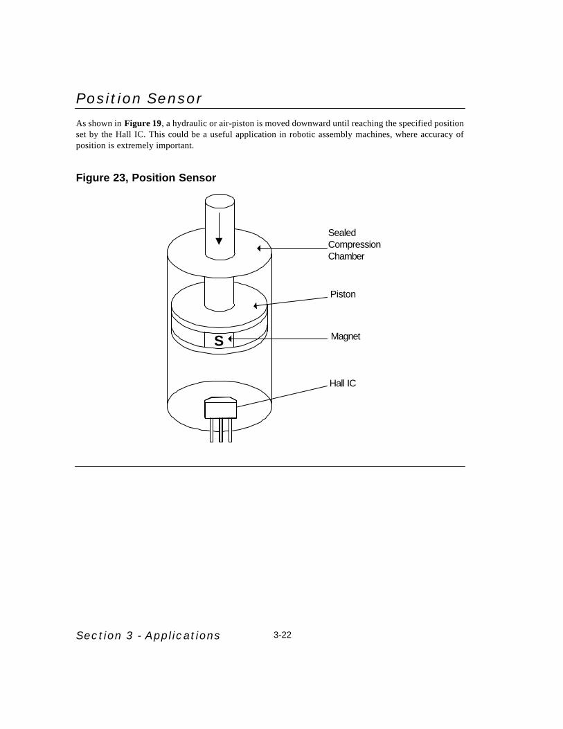
Position SensorAs shown in Figure 19, a hydraulic or air-piston is moved downward until reaching the specified positionset by the Hall IC. This could be a useful application in robotic assembly machines, where accuracy ofposition is extremely important.
Figure 23, Position Sensor
SealedCompressionChamber
Piston
Magnet
Hall IC
S

3-23 Section 3 - Applications
Geartooth Sensor
Magnetic Geartooth SensingThe need to sense speed and position of ferrous gears occurs in numerous industries. The ability to con-vert the repetitive passing teeth to an electrical impulse has been sought for many decades. purelymechanical systems have been used with the attendant issue of wear and failure limiting its use to lowspeed and low duty cycle applications.
Hall-Effect geartooth sensing makes use of the Hall element to sense the variation in flux found in the air-gap between a magnet and passing ferrous gearteeth. A modern approach is to convert the signal from theHall element to a digital value and then perform signal processing to create a digital output from thateffort. In the case of the Melexis geartooth sensing scheme each time the signal changes direction acounter is reset. If the signal level changes beyond the preset magnitude from the positive or negative peakthe output level is changed. This creates a digital zero speed peak detection speed sensor. It is immune toorientation requirements and cab follow the gear speed down to the cessation of motion. It will detect thefirst edge of the next tooth after immediately after power on. The digital signal processing does introducean uncertainty from quantization that is greater at larger speeds. Extremely demanding timing require-ments like those found in crank position sensors may suffer from the loss of accuracy at high speeds.Figure 24 shows the Melexis MLX90217 geartooth sensor operation.
Figure 24, Geartooth Sensor

Gear Tooth Sensor MagneticsIn order to detect the passing gear teeth with a Hall effect sensor it is necessary to provide a source ofmagnetic energy. The simple way to do this is to arrange a permanent magnet such that the axis of mag-netization is pointing toward to surface of the gear teeth. As a tooth moves across the surface of themagnet the flux will become attracted to the lower reluctance path provided by the ferrous steel struc-ture. When this occurs the flux density measured by the Hall element between the face of the sensor andthe gear tooth increases. Many schemes have been developed and some patented that use the variousattributes of the vector flux field and its changing nature to create zero speed Hall effect gear tooth sen-sors. Melexis has chosen to work with digital signal processing schemes and in this way minimize themagnetic circuit manipulation required of the end user. Put simply, by applying silicon "smarts" themagnetic subtlety and slight of hand is nearly eliminated.
Figure 25, Geartooth Flux Transitions
Magnetic modeling courtesy of AnSoftTM magnetic modeling software.

Section 3 - Applications 3-24
Brushless DC Motor SensorsThe use of Hall Effect Sensors in DC motors eliminates the friction, electrical noise and power loss asso-ciated with other types of mechanical commutation, such as brushes. Hall ICs provide a long mainte-nance-free life and offer greater flexibility with respect to direst interface with digital commands.
Figure 26, Brushless DC Motor Sensor
Figure 26, Brushless DC Motor ControllerThe US8881 is a brushless DC motor driver that was designed to meet the needs of high volume, lowcost motors which do not require the expensive options needed for servo or other closed loop applica-tions. The US8881 works with 3 HallIC latches, and provides all motor control via 6 external N-chan-nel FETs. A complete datasheet for this device is in section 4 of this book.
Figure 26, Brushless DCMotor Controller
N
N
N
S
S
S
22Ω
22Ω
22Ω
BLDC Motor
Filter ISENSE Resistor
Forward/Reverse
Thermal Switch
ROSC
COSC
Speed Adjust
22Ω
22Ω
VREF
22Ω
0.1µF
1000µF
V+ = 40 V
Brake
Counter Reset
0.1µF
24
23
22
21
20
19
18
17
16
15
14
13
2
3
4
5
6
7
8
9
10
11
12
Supply Voltage1 Cap Boost "A"
VREF
Out
Hall "A" Input
Hall "B" Input
Hall "C" Input
FWD/REV Input
Speed Adjust Input
Oscillator Control
(+)Current Limit (Brake)
Analog Ground
(-)Current Limit (Reset)
Power Ground
Gate Top "A"
Feedback "A"
Gate Bottom "A"
Cap Boost "B"
Gate Top "B"
Feedback "B"
Gate Bottom "B"
Gate Top "C"
Feedback "C"
Gate Bottom "C"
Cap Boost "C"
+
+
+
-
-
-
10µf
10µf
10µ f
UF4002(3 Places)
VREF
VREF
0.005 µ f
10K Ω
1KΩ
0.1µF
1000µF15V
500Ω
0.1µF
20µF
1K
1K

3-25 Section 3 - Applications
Programmable Motion SensorsThe use of Hall-Effect Sensors as an alternative to resistive potentiometers is a popular trend because ofthe advantages of non-contacting elements. in the past, linear Hall ICs were not very practical because ofbad temperature prformance and the ned for disctete trimming methods. Melexis created it’s programmable linear Hall ICs to solve both problems, leaving the end-user a veryaccurate sensor which is stable over temperature. The configurations are infinite, shown are two basic magntic circuits which will allow literally thousandsof position sensing applications.
Rotary MotionFigure 27 is the rotary method, where the Hall Ic is placed within a ring magnet, and the manetic field islinear to the rotary motion. Depending on the magnetic elements, this method can be linear up to 160o, buttypically, as shown 45o-90o of linearity can be easily achieved. This configuration is suitable for any rotaryposition application.
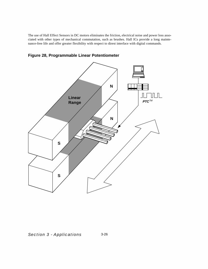
Linear MotionFigure 28 illustrates a linear position sensor, where a linear motion (as apposed to rotary motion) is trans-lated to a liear voltage via the Hall IC. The magnetic circuit shown is linear for approximately 50% of theentire length of magnet. For example, if the magnets were 1” long, they can be used to measure 1/2” ofmotion.
ProgrammingTo further enhance the system, the sensors are programmable to give optimal results. Details about pro-gramming are available in the MLX90215 and MLX90237 datasheets in section 4 of this book
Figure 27, Programmable Rotary Potentiometer
PTCTM
N
S
Section 3 - Applications 3-26
The use of Hall Effect Sensors in DC motors eliminates the friction, electrical noise and power loss asso-ciated with other types of mechanical commutation, such as brushes. Hall ICs provide a long mainte-nance-free life and offer greater flexibility with respect to direst interface with digital commands.
Figure 28, Programmable Linear Potentiometer
S
N
S
N
PTCTMLinearRange

3-27
Other Applications Some additional Hall Effect Sensor applications are listed below:
Application: Configuration: Refer to Figure:
Aircraft/Automotive:Tachometer Ring Magnet, Gear Tooth Sensor 7
Speed Indicator Ring Magnet, Gear Tooth Sensor 7
Roll Indicator Linear, Pendulum 12
Planing Angle Indicator Linear, Pendulum 12
Acceleration Indicator, Linear Pendulum 12
Fuel or Liquid-Level Sensor Level Detector 18
Seat Belt Sensor Proximity Switch 3
Airbag Ejection Sensor Proximity Switch 3
Power Window Sensor Proximity Switch 3
Door-Ajar Sensor Proximity Switch 3
Appliances:Water/Liquid Flow Digital, Ring Magnet 15
Washer Water Level Digital Float 18
Washer Tilt Sensor Digital, Pendulum 12
Washing Machine Motor Latch, DC Motor 20
Air conditioning Blower Latch, DC Motor 20
Refrigerator, Door Sensor Proximity Switch 3
Home, Tools and Security:Security Door Sensor Digital Vane Switch 5
Security Window Vibration Linear, Pendulum 12
Circular Saw Motor Latch, DC Motor 20
Overload Protection Current Limiter 13
Digital Combination Lock Rotary Switch 14
Mechanical Jam Protection Current Limiter 13
Power controller Switch with Circuit 16
Exercise Machine Counters Slide-by Switch 2
Computer Key Pads Push-button 17
Pinball Machine Buttons Push-button 17
Section 3 - Applications

The Programmable Sensor InterfaceA microcontroller sensor interface provides signal conditioning for a sensor element of any kind. Some types ofsensor elements that can be used are pressure sensors, strain gauges, load cells, thermistors, and potentiometers(position sensing). The MLX90308 sensor interface provides control over the offset, gain (or sensitivity), linearity and temperaturecompensation of the sensor’s signal using a microcontroller. In the past, such conditioning was done through discrete circuits. Such circuits required costly and unreliabletrimming methods, not to mention component count on the PC board. Because the MLX90308 is a microcon-troller, calibration is done digitally through a standard PC. The MLX90308 contains an 8-bit RISC core micro-controler, analog signal path, supply regulator, and EEPROM for storing compensation coefficients.Figure 29 illustrates a fundamental application of the MLX90308 and a bridge type pressure sensor element. Inthis application, the 90308 uses an external FET as a pass transistor to regulate the voltage to the sensor and theanalog portion of the IC. This is known as Absolute Voltage Mode, where voltage to the sensor and analog cir-cuit is regulated, independent of the supply voltage. The 90308 can be operated in Ratiometric Voltage Mode,where the output (VMO) is tied to an A/Dconverter sharing the same Supply and GND reference. A third wiring
16
15
14
13
12
11
10
9
1
2
3
4
5
6
7
8
IO1
IO2
TSTB
FLT
OFC
VBN
VBP
TMP
COMS
GND
CMN
CMO
VMO
VDD1
FET
VDD
ML
X9
03
08
G
S
D
External FETfor Regulation
PressureSensor
OilPressure
(psi)
Communications
GND
Signal Out
V+
Figure 29 - Oil Pressure GaugeCommunications
Signal OutGND
V+
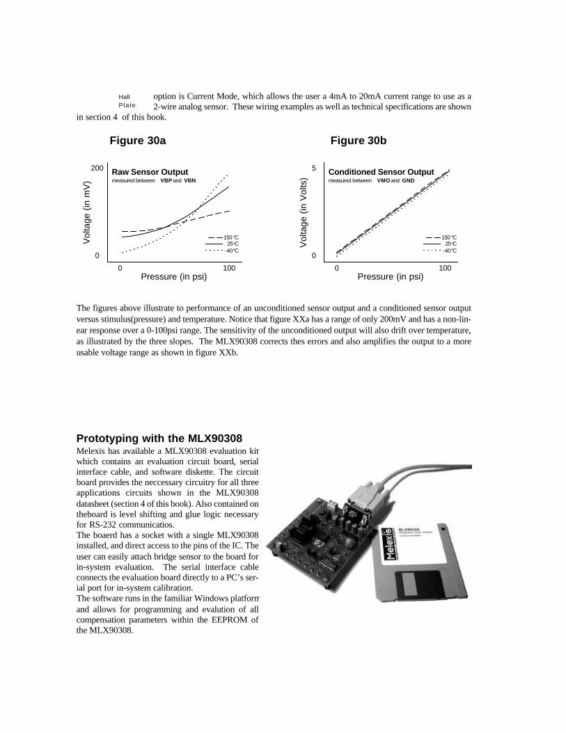
option is Current Mode, which allows the user a 4mA to 20mA current range to use as a2-wire analog sensor. These wiring examples as well as technical specifications are shown
in section 4 of this book.
The figures above illustrate to performance of an unconditioned sensor output and a conditioned sensor outputversus stimulus(pressure) and temperature. Notice that figure XXa has a range of only 200mV and has a non-lin-ear response over a 0-100psi range. The sensitivity of the unconditioned output will also drift over temperature,as illustrated by the three slopes. The MLX90308 corrects thes errors and also amplifies the output to a moreusable voltage range as shown in figure XXb.
Prototyping with the MLX90308Melexis has available a MLX90308 evaluation kitwhich contains an evaluation circuit board, serialinterface cable, and software diskette. The circuitboard provides the neccessary circuitry for all threeapplications circuits shown in the MLX90308datasheet (section 4 of this book). Also contained ontheboard is level shifting and glue logic necessaryfor RS-232 communicatios. The boaerd has a socket with a single MLX90308installed, and direct access to the pins of the IC. Theuser can easily attach bridge sensor to the board forin-system evaluation. The serial interface cableconnects the evaluation board directly to a PC’s ser-ial port for in-system calibration.The software runs in the familiar Windows platformand allows for programming and evalution of allcompensation parameters within the EEPROM ofthe MLX90308.
Pressure (in psi)0 100
Vol
tage
(in
mV
)
0
200 Raw Sensor Outputmeasured between VBP and VBN
Pressure (in psi)0 100
Vol
tage
(in
Vol
ts)
0
5 Conditioned Sensor Outputmeasured between VMO and GND
150 oC25oC
-40oC
150 oC25oC
-40oC
Figure 30a Figure 30b
HallPlate

Microcontroller Family OverviewMelexis is offering custom and semi-custom microcontrollers for automotive applications. Custom microcon-trollers provide the most cost affective solution by exactly matching the designers needs. Off-the-shelf micro-controllers typically force the customer to pay for features they don't need, or don't satisfy all of the systemrequirements and drive up the component count. Benefits such as increased reliability and design flexibility arerealized using a custom microcontroller. Typical applications are small system control and smart sensor inter-faces.
Melexis' custom microcontrollers are based on either an eight or sixteen bit RISC core. These can contain theexact analog and digital periphery the customer needs. Melexis is also embedding sensors on the same die.Chopper stabilized Hall effect sensors and temperature sensors are currently available. To withstand the auto-motive environment, these microcontrollers are designed to withstand an 80V load dump, -40°C to +150°C oper-ating die temperature, 6V to 26V supply and output shorts to ground or the battery.
Current applications include controllers for dashboard indicators, air conditioning, solenoid valve system, heat-ing system, electric window, sunroof and head cushion position, intelligent relay control, and sensor signal con-ditioning.
MemoryVersatile memory types and configurations are available. The microcontroller's I/O is entirely up to the cus-tomer. Melexis has a number of standard digital and analog interfaces available. Custom interfaces can be devel-oped if needed. Typical implementations include:
MX11 (8 bit core) MLX16 (16 bit core)
RAM, (bytes) 128 256 - 512ROM 2K 8 KE2PROM 32 128 - 256I/O(memory mapped) 8 16PROM 2 K 8 K
Digital InterfacesLogic I/O, up to 256 eight-bit ports are possible. The outputs can have high voltage (up to 80V), high current(up to 300 mA), or current limited capability. Also, digital outputs can have re-circulation diodes for drivingrelays.
Other digital function that are available are PWM outputs (0% to 100% duty cycle), timers, UART, watchdogtimer and display interfaces.
Custom digital interfaces or functions can be implemented to meet the customer's needs. The logic can bedesigned by the customer and implemented using VHDL or schematic format.

Analog InterfacesThere is a wide range of analog interfaces that can be integrated with the microcontroller. Multi-channel A/Dconverters in both 8 and 10 bit resolution . Band gap references for absolute measurements. On chip tempera-ture sensing for compensation of measurements, digital to analog conversion, phase locked loops (PLLs) as wellas operational amplifiers and comparators. Oscillators can be implemented either with external frequency defin-ing components or completely internal. Oscillators that are completely internal have frequency controlled froma value stored in EEPROM. Custom analog interfaces are also available to meet the customer's needs.PowerMaximum power consumption depends on the microcontroller and its exact configuration, clock frequency,loads, etc. The minimum power needed can be as low as 150 µA in a sleep or power down mode with the corestill active. Operating supply can be from 6 to 26 volts and load dump protection to 80 volts.
Development ToolsMelexis has developed a tools set and methodology which allows the user to develop their system concurrentlywith silicon development.
SoftwareMelexis has a full set of software tools to expedite the firmware development. For developing assembly languagefirmware, an assembler, linker and loader is used. A C compiler is also available for developing firmware. Thefirmware development can also be expedited by the software simulator. The simulator allows the developer torun or single step through the code as well as reading and forcing registers and memory locations.
HardwareA development board is available which contains a processor core with all of the program memory and periph-eral interfaces external to the processor. The processor core with the RAM and interrupt controller are containedin one Melexis chip. The firmware is executed from a user programmed PROM or EPROM. Peripheral inter-faces and functions are implemented within a Xilinx PLA and discrete components. The PLA can be repro-grammed by the user to develop the exact logic and interfaces needed. In addition to the development board,there is an in circuit emulator (ICE) available. The ICE replaces an external PROM/EPROM and allows controlover the program execution flow. The user can start, stop and single step though the program, similar to usingthe software simulator.
Prototype DevicesDevelopment is also made easier by prototype devices. These devices have the internal busses brought out topackage pins. This allows for use of external program memory or ICE while the peripheral interfaces are at theirfinal implementation


