CITY OF THORNTON – Standards and Specifications Revised: October 2012 300-i SECTION 300 - SANITARY SEWER SYSTEM STANDARDS TABLE OF CONTENTS PAGE 301 GENERAL PROVISIONS 300-1 302 GENERAL SPECIFICATIONS 300-1 302.1 Granting of Service 300-1 302.2 Application, Permit, Construction, and Acceptance Procedure 300-1 303 SANITARY SEWERS - DESIGN CRITERIA 300-1 303.1 General 300-1 303.2 Design Criteria 300-1 303.3 Flow Calculations 300-2 303.4 Lift Stations 300-2 303.5 Oversizing of Mains 300-3 303.6 Materials 300-3 303.7 Ground Cover 300-3 303.8 Location 300-3 303.9 Manholes 300-4 303.10 Grease and Sand/Oil Interceptors 300-4 303.11 Sewer Services 300-4 303.12 Prohibited Connections to Sewer 300-4 303.13 General Discharge Prohibitions 300-4 304 SANITARY SEWERS - CONSTRUCTION SPECIFICATIONS 300-5 304.1 Materials 300-5 304.2 Manholes 300-5 304.3 Installation of Pipe 300-6 304.4 Testing 300-7 305 SANITARY SEWER SERVICE LINES AND APPURTENANCES 300-8 CONSTRUCTION SPECIFICATIONS 305.1 General 300-8 305.2 Materials 300-8 305.3 Pipe Bedding 300-9 305.4 Location and Alignment of Service 300-9 305.5 Service Stub-Ins to Property Line 300-9 305.6 Connections 300-9 305.7 Commercial and/or Industrial Manholes 300-10 305.8 Abandoning Existing Service Taps 300-11 305.9 Abandoning Existing Sewer Main 300-11 305.10Sanitary Sewer Service Repair 300-11
Transcript
CITY OF THORNTON – Standards and Specifications Revised: October 2012
300-i
SECTION 300 - SANITARY SEWER SYSTEM STANDARDS TABLE OF CONTENTS PAGE 301 GENERAL PROVISIONS 300-1 302 GENERAL SPECIFICATIONS 300-1 302.1 Granting of Service 300-1 302.2 Application, Permit, Construction, and Acceptance Procedure 300-1 303 SANITARY SEWERS - DESIGN CRITERIA 300-1 303.1 General 300-1 303.2 Design Criteria 300-1 303.3 Flow Calculations 300-2 303.4 Lift Stations 300-2 303.5 Oversizing of Mains 300-3 303.6 Materials 300-3 303.7 Ground Cover 300-3 303.8 Location 300-3 303.9 Manholes 300-4 303.10 Grease and Sand/Oil Interceptors 300-4 303.11 Sewer Services 300-4 303.12 Prohibited Connections to Sewer 300-4 303.13 General Discharge Prohibitions 300-4 304 SANITARY SEWERS - CONSTRUCTION SPECIFICATIONS 300-5 304.1 Materials 300-5 304.2 Manholes 300-5 304.3 Installation of Pipe 300-6 304.4 Testing 300-7 305 SANITARY SEWER SERVICE LINES AND APPURTENANCES 300-8 CONSTRUCTION SPECIFICATIONS 305.1 General 300-8 305.2 Materials 300-8 305.3 Pipe Bedding 300-9 305.4 Location and Alignment of Service 300-9 305.5 Service Stub-Ins to Property Line 300-9 305.6 Connections 300-9 305.7 Commercial and/or Industrial Manholes 300-10 305.8 Abandoning Existing Service Taps 300-11 305.9 Abandoning Existing Sewer Main 300-11 305.10Sanitary Sewer Service Repair 300-11
CITY OF THORNTON – Standards and Specifications Revised: October 2012
300-ii
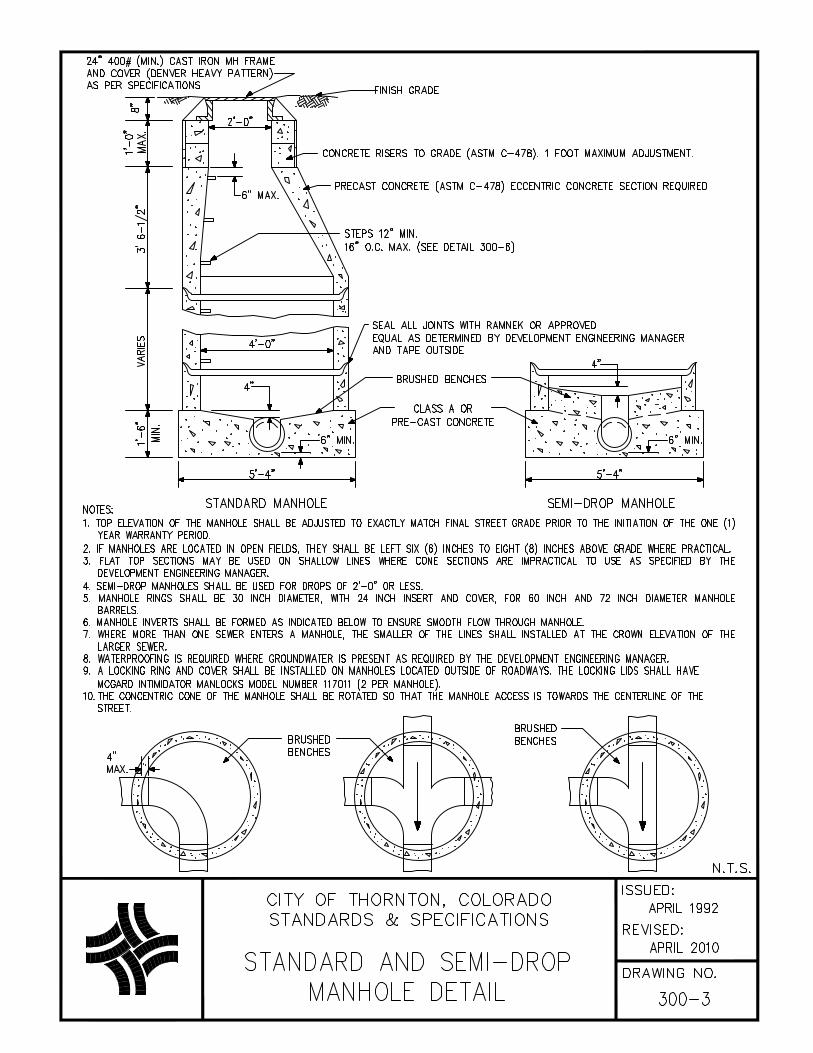
DETAIL DRAWINGS 300-1 Sewer Main Lining and Rehabilitation Detail 300-2 Sewer Main Bedding, Underdrain and Service Connection Detail 300-3 Standard and Semi-Drop Manhole Detail 300-4A Drop Manhole 8in and 12in lines A Detail 300-4B Drop Manhole 15in and larger B Detail 300-5 Marker Post Detail 300-6 Plastic Manhole Step Detail 300-7 Standard Clean-Out Detail 300-8A Sanitary Sewer ARV and Vent Vaults Detail 300-8B Sanitary Sewer ARV Detail 300-8C Sanitary Sewer ARV Manhole and Vent Manhole Base Footing
Details
CITY OF THORNTON – Standards and Specifications Revised: October 2012
300-16
SECTION 300 - SANITARY SEWER SYSTEM STANDARDS 301 GENERAL PROVISIONS
These standards are promulgated by the Utilities Director of the City in accordance with the authority contained in the Thornton City Code. Improvements shall also be in conformance with Chapter 74 of the Thornton City Code.
302 GENERAL SPECIFICATIONS 302.1 Granting of Service
Sanitary sewer shall be extended at the requestor's expense, when it has been determined that the City has the capability and capacity to serve the area, provided that the area to be served is located within the Thornton sanitary sewer service area and provided that the Responsible Party can show evidence of fee ownership of the property to be serviced. The request for service must be in compliance with stipulations contained in all utilities agreements entered into by the City and said applicant as well as in compliance with all applicable City ordinances, codes and charter principles.
302.2 Application, Permit, Construction, and Acceptance Procedure
Refer to Section 100 for City application, permitting, construction, and acceptance procedures.
303 SANITARY SEWERS DESIGN CRITERIA 303.1 General
A. The purpose of these Standards and Specifications is to ensure that only proven high quality materials are
installed with first class workmanship. Determination of the best materials and construction methods are based upon lowest life cycle costs, not necessarily upon lowest initial costs. The sizing and layout of the system are part of the total consideration of design, operations, and maintenance of a sanitary sewer system that yields optimum quality service at the lowest total cost to the consumer.
B. Sanitary sewer mains and appurtenances shall be constructed in conformance with these Standards and
Specifications and shall be designed by or under the direct supervision of a registered PE licensed to practice in the State of Colorado. Refer to the checklist in section 100 for construction drawing requirements related to sanitary sewer.
303.2 Design Criteria
A. Sanitary sewers must be designed to carry the peak discharge with the pipe being no more than 50 % of
maximum flow capacity (q/Q) for mains smaller than 15 inches in diameter or 80 % of maximum flow capacity (q/Q) for mains 15 inches in diameter and larger. In manholes, sewers shall be designed so that the crown of the invert sewers match, and the manhole shall be filleted as shown on Detail 300-3. The mains shall also be able to transport suspended material such that deposits in the sewer are precluded. It is essential that the sewer have capacity for peak hourly sewage flow and adequate velocity at minimum sewage flows.
B. The Manning formula, with an "n" value of 0.013, shall be utilized for the sizing of sanitary sewer mains.
The minimum diameter for sanitary sewer mains shall be eight (8) inches. C. The following are the minimum and maximum slopes generally permissible for sewer collection and outfall
mains:
SEWER SIZE (inches) MINIMUM SLOPE MAXIMUM SLOPE
Sanitary Sewer Services
4 6
2.00% 1.00%
8.00% 8.00%
Sanitary sewer collection and outfall mains
8 10 12 15 18 21 24 30
0.40% 0.28% 0.22% 0.15% 0.12% 0.10% 0.08% 0.06%
5.00% 4.00% 3.00% 2.50% 2.00% 1.50% 1.20% 0.90%
CITY OF THORNTON – Standards and Specifications Revised: October 2012
300-17
The maximum slope on an eight (8) inch sewer line may be increased to seven (7) % where necessary to match approved street slope and is not economically feasible to place sewer on a lesser slope. Increasing the pipe diameter exclusively to utilize a lesser slope is not permitted.
303.3 Flow Calculations
A. Flow calculations shall be submitted to the Development Engineering Division for review along with the
engineering plans. B. Calculations shall include:
1. The average and hourly peak quantity of sewage flow projected to be generated by the project. 2. The velocity of flow in the proposed sewer. 3. The % of pipe capacity utilized (q/Q), including anticipated peak flows from all upstream properties. 4. The impact on downstream sewer systems from the proposed development to the nearest
transmission main. 5. The quantity and type of discharge of an unusual nature such as swimming pool drainage, cooling
water, etc. C. The following design criteria shall be used for projecting wastewater flows, unless more site specific criteria
are available: 1. Residential:
a. 80 gallons per person per day (gpd)
i. low density (less than 5 DU/Ac.) = 3.45 people/unit ii. mid density (5 to 12 DU/Ac.) = 2.45 people/unit iii. high density (more than 12 DU/Ac.) = 2.20 people/unit
2. Commercial and Industrial:
600 gallons per acre per day
Peaking Factor - Peak hourly factor shall be calculated utilizing the following equation:
295.0
72.1F
PF = [3.5 max., 2.6 min.]
where PF = Peaking Factor
F = Average Flow in MGD D. If flow monitoring is determined to be needed in order to check existing sewers for available capacity, the
Responsible Party is required to hire a contractor to perform the work. The contractor will need to contact Development Engineering to coordinate the location and scheduling of the flow monitoring. All flow monitoring equipment shall be utilized for a minimum of one (1) week, and shall be securely fastened so that if the equipment does become loose, it will not be conveyed into the downstream pipes.
303.4 Lift Stations
A. Where lift stations are proposed, a basin study shall be completed by the Responsible Party’s engineer.
The basin shall include properties other than the proposed development, and costs for sizing of facilities within the basin shall be allocated as documented in Chapter 74 of the City Code.
B. Lift stations shall be equipped with an odor control device, and no lift station shall be permitted within 100
feet of a residential lot. The Responsible Party’s engineer shall submit a pretreatment plan for review and approval by the Development Engineering Manager. The pretreatment shall provide effective control of odors in the downstream sewerage system.
C. Lift stations and force mains shall be sized for peak hour wastewater flows. Force mains shall be sized for
a maximum velocity of six (6) fps, minimum velocity of two (2) fps. D. Air relief valves shall be installed on the high point of all sanitary sewer force mains in accordance with
Details 300-8A, 8B, and 8C.
CITY OF THORNTON – Standards and Specifications Revised: October 2012
300-18
E. Lift stations shall be Gorman-Rupp package system with submersible pump and Smith-Loveless package system design for high lift applications (wet well and dry well) when pump cannot provide the required head pressure, or equivalent subject to approval of the Development Engineering Manager.
F. Controls and electrical components shall be housed in a weatherproof enclosure above ground and
adjacent to the wet well. The force main leaving the lift station shall be constructed of C-900 DR-14 pressure pipe
G. Emergency power shall be provided for the lift station and sized to run the entire lift station at capacity. A
diesel generator shall be provided in a walk-in above-ground enclosure on a concrete pad. The fuel tank shall be sized to permit 24 hours of run time. The Responsible Party shall install a generator silencer or masonry wall as determined by the Development Engineering Manager to decrease the level of noise created by the emergency generator when adjacent to residential property.
H. Shop drawings for the lift station and related equipment shall be submitted to the Development
Engineering Manager for approval. Construction shall not begin on lift station until shop drawings have been approved by the Development Engineering Manager and the Colorado Department of Public Health and Environment.
303.5 Oversizing of Mains
Oversizing of mains may be required by the City, as documented in Chapter 74 of the City Code.
303.6 Materials
A. Only sanitary sewer mains constructed of the following materials are permitted:
B. These materials shall be consistent from manhole to manhole.
303.7 Ground Cover
A. Sewer mains and services shall be designed so that a minimum of four (4) feet of cover exists over the
pipe after final grade has been established. B. Sewer mains and services which have less than four (4) feet of cover or more than 20 feet of cover shall
be installed using SDR 26 or C-900 DR-14. When a sewer main crosses underneath a stream, irrigation ditch, or storm drainage ditch, casing of the facility is required.
303.8 Location
A. Sewers shall be installed in dedicated street rights of way or exclusive easements. City sanitary sewer
mains shall not cross through residential lots. Location for these sewers shall be 10 feet from the center line on the south or west side of the street. Streets with asphalt widths less than 32 feet shall have sewers located five (5) feet from the center line on the south or west side. In addition, a minimum separation of five (5) feet from the lip of pan or edge of pavement is required for sanitary sewer.
B. Sewer mains shall be installed in exclusive easements, when, as determined by the Development
Engineering Manager, it is not practical to make such installation in a dedicated street ROW. Under no circumstances shall any structures be constructed within these easements or ROW without prior approval, including terms and conditions, as set by the City. The minimum width requirements for sanitary sewer easements are 20 feet or twice the depth of the pipe, whichever is greater. The pipeline shall be centered in the easement, and offset a minimum of five (5) feet from any property line. In the event two (2) utilities share the same easement, the minimum width for the easement shall be 30 feet, and for three (3) public utilities, the width shall be 40 feet, etc. All easements in residential areas shall be in a dedicated tract with a minimum width of 40 feet.
C. Sanitary sewer mains shall be located so that they are accessible. D. Sanitary sewer mains shall not be installed within five (5) feet of any concrete, such as sidewalks, curb,
gutter, or cross pans except for 90 degree crossings E. No curvilinear sewers shall be permitted. F. Sanitary sewers shall not be installed in drainage ditches (except at 90 degree crossings) or detention
ponds. G. The minimum vertical separation between pipes shall be 18 inches, and the minimum horizontal separation
between pipes shall be 10 feet. Distances shall be measured edge to edge.
CITY OF THORNTON – Standards and Specifications Revised: October 2012
300-19
303.9 Manholes
A. Manholes shall be installed at both ends of each section of sewer, at changes in grade, size, or alignment,
at intersections and at distances not greater than 450 feet for all sewers. B. Manholes shall be combined when they are located at the apex of a sewer main, and are within 50 feet of
another manhole C. A drop manhole shall be provided for a sewer entering a manhole at an invert elevation of 24 inches or
more above the manhole invert. Where the difference in elevation between the incoming sewer invert and the manhole invert is less than 24 inches, the invert shall be shaped in a filleted fashion to prevent solids deposition, as shown in Detail 300-3. Drops should be avoided whenever possible.
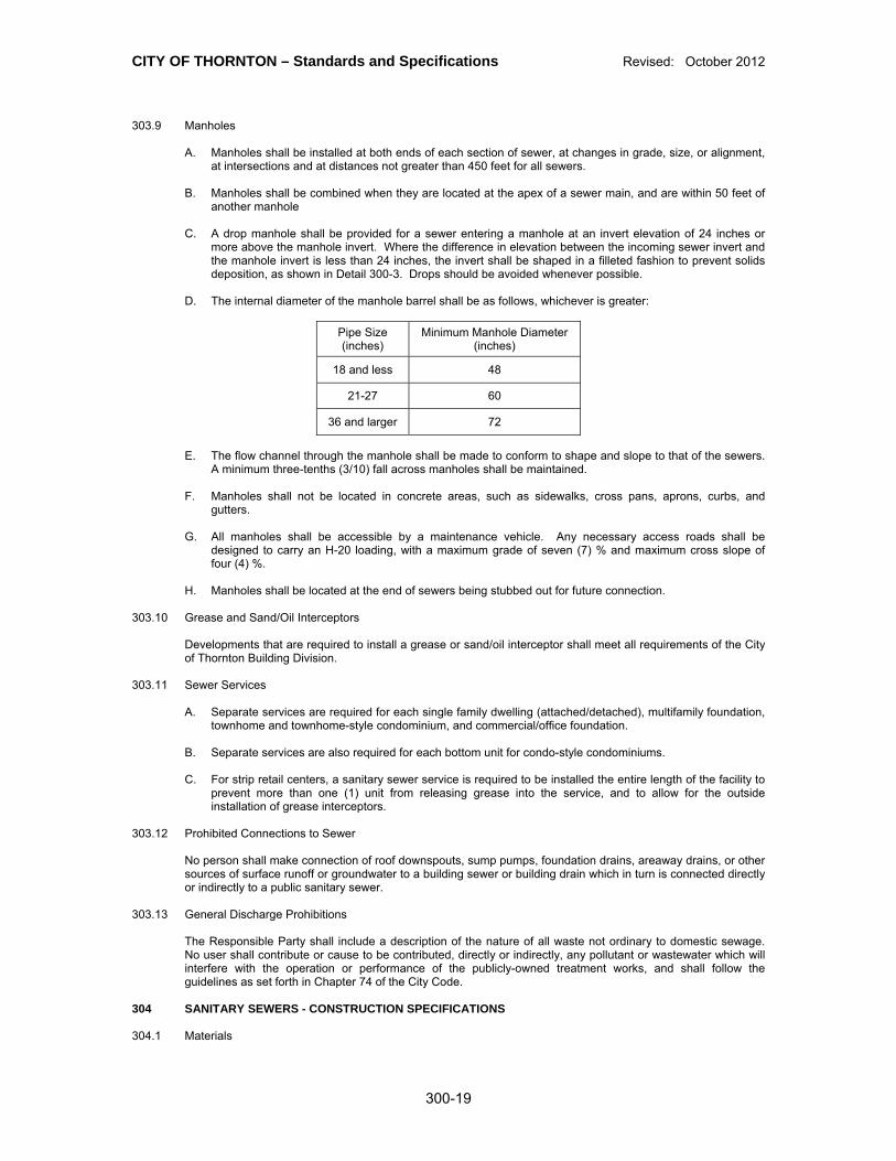
D. The internal diameter of the manhole barrel shall be as follows, whichever is greater:
Pipe Size (inches)
Minimum Manhole Diameter (inches)
18 and less 48
21-27 60
36 and larger 72
E. The flow channel through the manhole shall be made to conform to shape and slope to that of the sewers.
A minimum three-tenths (3/10) fall across manholes shall be maintained. F. Manholes shall not be located in concrete areas, such as sidewalks, cross pans, aprons, curbs, and
gutters. G. All manholes shall be accessible by a maintenance vehicle. Any necessary access roads shall be
designed to carry an H-20 loading, with a maximum grade of seven (7) % and maximum cross slope of four (4) %.
H. Manholes shall be located at the end of sewers being stubbed out for future connection. 303.10 Grease and Sand/Oil Interceptors
Developments that are required to install a grease or sand/oil interceptor shall meet all requirements of the City of Thornton Building Division.
303.11 Sewer Services
A. Separate services are required for each single family dwelling (attached/detached), multifamily foundation,
townhome and townhome-style condominium, and commercial/office foundation. B. Separate services are also required for each bottom unit for condo-style condominiums. C. For strip retail centers, a sanitary sewer service is required to be installed the entire length of the facility to
prevent more than one (1) unit from releasing grease into the service, and to allow for the outside installation of grease interceptors.
303.12 Prohibited Connections to Sewer
No person shall make connection of roof downspouts, sump pumps, foundation drains, areaway drains, or other sources of surface runoff or groundwater to a building sewer or building drain which in turn is connected directly or indirectly to a public sanitary sewer.
303.13 General Discharge Prohibitions
The Responsible Party shall include a description of the nature of all waste not ordinary to domestic sewage. No user shall contribute or cause to be contributed, directly or indirectly, any pollutant or wastewater which will interfere with the operation or performance of the publicly-owned treatment works, and shall follow the guidelines as set forth in Chapter 74 of the City Code.
304 SANITARY SEWERS - CONSTRUCTION SPECIFICATIONS 304.1 Materials
CITY OF THORNTON – Standards and Specifications Revised: October 2012
300-20
A. Materials furnished shall be new and undamaged. Everything necessary to complete installations shall be
furnished and installed whether shown on approved drawings or not and installations shall be completed as fully operational.
B. Acceptance of materials or the waiving of inspection thereof shall in no way relieve the Responsible Party
of the responsibility for furnishing materials meeting the requirements of the specifications. The City reserves the right to direct or deny use of certain types of materials in specific circumstances.
C. Materials delivered to the job site shall be adequately housed and protected so as to ensure the
preservation of their quality and fitness for the work.
1. Polyvinyl Chloride Pipe
a. Pipe materials and fittings shall meet the extra strength minimum requirements of ASTM D-3034, SDR-35, or latest revision thereof.
b. Pipe shall be subjected to drop impact tests in accordance with ASTM D-2444. c. Fittings and accessories shall be as manufactured and furnished by the pipe supplier or
approved equal, as determined by the Development Engineering Manager, and have bell and/or spigot configurations compatible with that of the pipe.
d. Pipe stiffness for pipe shall be tested in accordance with ASTM D-2412, while joint tightness
shall be tested in accordance with ASTM D-3212. e. Installation shall be in accordance with Ring-Tite PVC Gravity Sewer Pipe Installation Guide TR-
614A published by John-Mansville, except as modified by these Standards and Specifications. f. If deflection limits exceed five (5) %, the Responsible Party shall be responsible for removing the
existing pipe and installing a new pipe material under the direction of the Development Engineering Manager.
g. The manufacturer shall furnish a certified statement that the inspection and the specified tests
have been made and the results thereof comply with the requirements of the applicable standard(s) herein specified. A copy of the certification shall be sent to the Development Engineering Manager upon request.
h. Solvent cement joints are not permitted.
2. Polyvinyl Chloride Pressure Pipe
Refer to Subsection 204.1(B) of these Standards and Specifications. 304.2. Manholes – Detail 300-3
A. Manhole Construction
1. Whenever the manhole is left unattended, including prior to any connection, the manhole cover or a
temporary cover shall be installed at the opening. Temporary covers shall be of such design as to prevent ground/storm water, children, or animals from entering sewer. Temporary covers shall be subject to approval by the Development Engineering Manager.
2. Sewer connections to existing manholes where there is no existing pipe stubbed out shall be made in
such a manner that the finished work shall conform as nearly as practical to the essential requirements specified for new manholes. The Responsible Party shall break out as small an opening in the existing manhole as necessary to insert the new sewer. The existing concrete foundation bench shall be chipped to the cross section of the new pipe in order to form a smooth, continuous invert similar to what would be formed in a new concrete base. Portland cement grout shall be used as necessary to smoothly finish the new invert and to seal the new sewers so the junction is watertight.
3. Steel pipe manhole marking poles will be required as depicted on Detail 300-5. In cultivated areas,
manholes shall be left below grade; considering the type of equipment being used for the cultivated area, the ring and cover elevations shall be lower in order to protect structure from damage, and properly marked by a marker post (Detail 300-5), located at the nearest possible fence line. Final elevation of manholes is to be at the discretion of the Development Engineering Manager.
4. Refer to Detail 300-3 for additional manhole requirements.
CITY OF THORNTON – Standards and Specifications Revised: October 2012
300-21
B. Waterproofing
Manholes shall be waterproofed where ground water or other water sources are present, as determined by the Development Engineering Manager, that could be detrimental to the function of the structure. Method of waterproofing shall be submitted by the Responsible Party for review and approval by the Development Engineering Manager.
C. Lining and Rehabilitation
1. All new manholes installed downstream of a lift station along the sewer mainline shall be lined in
accordance with these specifications. In addition, all manholes within 1500 feet installed on a distribution line connected to a sewer mainline downstream from a lift station shall be lined in accordance with Detail 300-1.
2. If a lift station is installed as part of a development project, the developer shall line all new manholes
as specified above and rehabilitate all existing downstream manholes as specified above. Existing manholes that have been previously lined or rehabilitated will not be required to be rehabilitated.
D. Drop Manholes – Detail 300-4A & 300-4B
A drop manhole shall be constructed at manhole locations where the incoming pipe invert is two (2) feet or more above the manhole invert.
E. Semi-Drop Manholes – Detail 300-3
A semi-drop manhole shall be constructed at manholes where the incoming pipe invert is up to two (2) feet above the manhole invert pipe outlet. Refer to Detail 300-3 for semi-drop manholes.
304.3 Installation of Pipe
A. Refer to Section 100 for excavation, dewatering, pipe bedding, testing, backfill, and compaction
requirements. B. Pipe and fittings shall be loaded and unloaded by lifting so as to avoid shock or damage. Under no
circumstances shall such material be dropped. Before the placing of pipe in the trench, each pipe or fitting shall be thoroughly cleaned of foreign material, kept clean and examined for cracks or defects before installation. The Development Engineering Manager may reject any pipe which shows discoloration due to the sun.
C. Joint lubricant shall be as supplied by the pipe manufacturer. D. The pipe shall be laid upstream with spigot ends pointing downstream. The pipe shall be placed true to line
and grade with ends abutting, carefully centered and with a smooth invert at the joint. The joint shall be made in a workmanlike manner so as to be watertight. New installations shall be complete and flushed prior to connecting to existing pipes.
E. Whenever the pipe is left unattended, including prior to any connection, temporary plugs shall be installed
at openings. Temporary plugs shall be watertight, standard cast iron and of such design as to prevent ground/storm water, children, or animals from entering the pipe. Temporary plugs shall be subject to approval by the Development Engineering Manager.
F. No pipe or appurtenant structure shall be installed upon a foundation into which frost has penetrated or at
any time when the Development Engineering Manager deems there is a danger of ice formation or frost penetration at the bottom of the excavation. No pipe or appurtenant structure shall be installed unless backfilling can be completed before the formation of ice and frost.
G. Immediately before joining two (2) lengths of pipe, the inside of the bell, the outside of the spigot end, and
the gasket shall be thoroughly cleaned. Caution shall be exercised to ensure that the correct type of gasket is used. A thin film of gasket lubricant shall be applied to either the inside face of the gasket or the spigot end of the pipe or both, according to the pipe manufacturer's installation procedure.
H. The spigot end of the pipe shall be placed in the socket with care to prevent the joint from contacting the
ground. The joint shall be completed by pushing the pipe home with a slow, steady pressure. Stabbing shall not be permitted.
I. Repaired couplings shall not be permitted. J. Sewer lines installed at minimum grade shall have final grade field verified by a Professional Surveyor,
registered in the State of Colorado, and a television inspection, prior to backfill, at the Responsible Party's
CITY OF THORNTON – Standards and Specifications Revised: October 2012
300-22
expense. This shall also be performed after the backfill and compaction of trench area is complete in place above the pipe.
K. Under no circumstances shall sewer lines be installed beneath any concrete, such as sidewalks, curbs, or
gutters. L. In-line "Y" shall be installed at all service line locations in new mains.
304.4 Testing
A. Sanitary sewer pipe and appurtenances shall be cleaned and tested after backfill operations have been
completed and acceptable compaction test results have been submitted to the Development Engineering Manager.
B. New sanitary sewer installations shall be televised and as-built shots taken to verify design slope
requirements by the responsible party after backfill operations have been completed. The results of the inspection and video shall be submitted to the Development Engineering Manager for approval. Water line installation may not begin until acceptable televised testing video and as-built shots have been submitted and reviewed by the City.
C. The Responsible Party shall have sewers jet washed on new installation prior to the initial television
inspection completed by the City. Debris resulting from the cleaning shall be removed before entering the City's existing sewer, by either some type of plug or elbow to catch debris. Material shall be removed from the site and disposed of by the Responsible Party. If on the initial television inspection the cleaning is unsatisfactory and prevents the television inspection from being completed, the Responsible Party shall reclean the sewer and shall be responsible for costs incurred by a second television inspection. The low pressure air test shall be required on the entire length of pipe installations.
D. Any damages to the pipe caused by cleaning or testing operations shall be repaired or replaced by the
Responsible Party at his own expense. Should the pipe fail to meet the requirements of the low pressure air test or infiltration of ground water is noted, the Responsible Party shall determine the source or sources of the leakage and shall replace defective materials or workmanship. Replacement of defective materials or workmanship as above noted shall be the financial responsibility of the Responsible Party. Pipe which fails to meet these requirements shall be repaired or replaced and retested in accordance with these requirements.
E. New sanitary sewer installations will be televised by the City for initial acceptance after the installation,
cleaning, testing, and final lift of asphalt are complete. Inspection reports and videos shall be available for review by the Responsible Party. The Responsible Party shall be responsible for any repairs or replacement of any portions of the pipeline that are determined defective by the television inspections.
F. Prior to the final acceptance there shall be another television inspection performed by the City. If there are
any discrepancies, a punch list shall be formulated and sent to the Responsible Party. Any discrepancies must be repaired prior to final acceptance being granted.
G. Low Pressure Air Test
1. Pipe outlets shall be plugged with suitable test plugs. Pipe may be tested without pre-wetting. If the
pipeline to be tested is submerged in groundwater, the Responsible Party shall determine the groundwater elevation at the test location and provide it to the Development Engineering Manager. The backpressure on the pipe due to groundwater shall be determined and the internal pipeline test pressure shall be established at 4.0 psi (gauge) in excess thereof. Add air slowly to the portions of the pipe being tested. After the pipe has been filled to the required pressure, allow at least two (2) minutes for the air-temperature to stabilize, adding only the amount of air necessary to maintain the test pressure. After the two (2) minute period, disconnect the air supply and allow the initial pressure to drop to 3.5 psi (gauge) in excess of the groundwater back pressure.
2. The time interval required for the sewer internal pressure to drop from 3.5 psi (gauge) to 2.5 psi (gauge) above the excess of ground water backpressure shall be measured and recorded.
3. The basis for acceptance of the air test shall be the minimum time required for the internal pressure to drop 1.0 psi (gauge). The minimum allowable time in seconds shall be in accordance with the following tables. The minimum allowable pressure drop time is computed based upon an allowable leakage rate not to exceed 0.003 cfm per square foot of internal pipe surface. Sewers 15 inches in diameter and smaller shall be tested from manhole to manhole. Sewers 18 inches in diameter and larger shall be tested in lengths such that the total loss is no less than two (2) cfm when computed using an allowable rate of 0.003 cfm per square foot of internal surface.
CITY OF THORNTON – Standards and Specifications Revised: October 2012
300-23
Minimum allowable pressure drop times for pipe 15 inches in diameter and smaller (in seconds):
The minimum allowable pressure drop time when using the maximum testing length is 120 seconds.
4. Sewers 36 inches in diameter shall be tested one (1) joint at a time. 5. If it appears that excessive infiltration is present after the air tests have been completed, the
Development Engineering Manager may require an infiltration test prior to final acceptance. Excessive infiltration may be the cause for rejection. The Development Engineering Manager shall be the sole judge of whether or not the infiltration test is required.
6. The Responsible Party shall follow precautions necessary to perform a safe and successful test.
Plugs used to isolate the line for the air test must be securely braced to avoid the unintentional release of the plug. Gauges, air piping manifolds, and control valves shall be located above ground. No one shall be permitted to enter a manhole when a plugged pipe is under pressure. Air testing apparatus shall be equipped with a pressure relief device designed to relieve the pressure when in excess of six (6) psi (gauge).
305 SANITARY SEWER SERVICES AND APPURTENANCES CONSTRUCTION SPECIFICATIONS 305.1 General
Sanitary sewer service construction connecting to the City sanitary sewer system shall be done in accordance with these Standards and Specifications, which cover new sanitary sewer service construction and repairs to existing services from the sewer main to the property line. Refer to Sections 100 and 304 and 305 for installation and testing procedures for sanitary services and appurtenances.
305.2 Materials
A. Materials furnished shall be new and undamaged. Everything necessary to complete installations shall be
furnished and installed whether shown on approved drawings or not and installations shall be completed as fully operable.
B. Acceptance of materials or the waiving of inspection thereof shall in no way relieve the Responsible Party
of the responsibility for furnishing materials meeting the requirements of the specifications. C. The City of Thornton reserves the right to direct or deny use of certain types of materials in specific
circumstances. D. Materials delivered to the job site shall be adequately housed and protected so as to ensure the
preservation of their quality and fitness for the work. E. Polyvinyl Chloride Pipe
Refer to Subsection 304.1(C)(1) of these Standards and Specifications.
F. Polyvinyl Chloride Pressure Pipe
CITY OF THORNTON – Standards and Specifications Revised: October 2012
300-24
Refer to Subsection 204.1(B) of these Standards and Specifications.
G. Manholes
Refer to Subsection 304.2 of these Standards and Specifications.
305.3 Pipe Bedding – Detail 300-2
Section 100 of these Standards and Specifications are applicable except that four (4) inch and six (6) inch services require a minimum bedding depth of eight (8) inches as shown in the detail drawing.
305.4 Location and Alignment of Service
Sanitary sewer services shall be constructed on the shortest and straightest route possible. At no time shall the service be any closer than five (5) feet to the side property, and except when installed in easements in commercial areas, no service may be constructed through or in front of any adjoining property. When possible, the service shall be located five (5) feet toward the low side of the lot from the center of the lot. Services are not to extend beneath driveways. Sewer and water services must be a minimum of 10 feet apart horizontally or concrete encasement of the sewer or special protection shall be required.
305.5 Service Stub-Ins to Property Line – Detail 200-2
Service stub-ins shall be extended at least to property line and shall be plugged with a watertight compression stop. Adjacent to the end of the stub-in, a four (4) foot length of two (2) inch by four (4) inch wood marker (or a four (4) foot length steel fence post) shall be placed in a vertical position prior to backfilling. The responsible party shall place a chiseled "X" in the curb head at the location where the service crosses underneath the curb. This two (2) inch by four (4) inch wooden marker shall remain in place until service locations are chiseled on the curb. If the two (2) inch by four (4) inch wood marker is not present at time of chiseling, the Responsible Party shall bear the expense of reaffirming the location of the service stub-out by re-excavation. The Responsible Party shall take measurements of distances from manholes to service taps and give this information to the City.
305.6 Connections
A. Where wyes have not or could not have been installed in the main sewer, the Responsible Party shall
excavate around the main and prepare the main for tapping. The main shall then be tapped by the Responsible Party at the expense of the Responsible Party. The connection shall be watertight and at a 45 degree angle above the pipe horizontal center line. Projection of the sewer service pipe inside the sewer main shall not be permitted. Approved tees or sewer service saddles shall be used to connect the service to the sewer main.
B. No aluminum saddles shall be permitted. Plastic saddles shall be attached to the mains utilizing either
epoxies or stainless steel straps. The City shall inspect the main and saddle at every tap prior to backfilling. In the event the tap is covered before it is inspected, it shall be dug out by the Responsible Party and any concrete or mortar around the fitting shall be removed to allow visual inspection of the tap and the main. If the main sewer is cracked or broken during the process of locating and tapping, it shall be repaired immediately either by replacing the broken section or by placing a minimum of nine (9) inches of concrete above, at the sides and below the main pipe parallel for the width of the excavation. The method of repair shall be chosen by the Development Engineering Manager. Lines in service must be machine tapped.
C. A manhole shall be installed instead of a service tap when a six (6) inch connection is to be made on an
existing eight (8) inch or 10 inch sewer. Six (6) inch connections may be made without a manhole on new installations with the use of a wye. If a wye cannot be used, a manhole shall be required on eight (8) inch and 10 inch new sewers. Service taps to existing manholes shall not be permitted.
D. Sewer mains shall be laid through manholes at the end of cul-de-sacs. One (1) joint of pipe and plugged
wyes shall be installed in order that the end of the cul-de-sac may be serviced without tapping into the manhole. No more than two (2) wyes may be located on that joint of pipe laid through the manhole.
E. No more than three (3) one-fourth (¼) bends shall be permitted in any sanitary sewer service line. Where
services are longer than 100 feet, cleanouts shall be required as depicted in Detail 300-7. F. All sewers connecting to existing main lines shall be plugged at the manhole. The plug shall be a cast iron
wing nut type and connected to the top step of the manhole using a stainless steel cable or approved equal. The plug shall remain installed and be maintained until initial acceptance of the work. Once initial acceptance of the work is received, the plug shall be removed and the sewer will be allowed to transmit wastewater into the existing main line.
305.7 Commercial and/or Industrial Manholes
CITY OF THORNTON – Standards and Specifications Revised: October 2012
300-25
A manhole may be required where so specified by the Development Engineering Manager in order to have samples taken if industrial wastes are suspected. Such a manhole would be located on the commercial service, so samples could be taken before such fluids could reach the sanitary sewer main.
305.8 Abandoning Existing Service Taps
If it has been determined by the Development Engineering Manager that a service line is to be temporarily abandoned in conjunction with a development, it shall be removed to the property line and capped. If the abandonment is permanent, then it shall be disconnected from the main line, a cap or plug shall be installed in the wye and it shall be encased in concrete.
305.9 Abandoning Existing Sewer Main
If it has been determined by the Development Engineering Manager that sanitary sewer shall be abandoned in conjunction with a development, the sewer shall be removed or flash/flow filled in place.
305.10 Sanitary Sewer Service Repair
All sewer service repairs outside of City rights-of-way shall follow the currently adopted International Plumbing Code and any amendments.