Contract Administration Structures 500 04/17 SECTION 500 – STRUCTURES 505.00 Piling. General Pile Driving Administration Procedure A. The Contractor must submit a completed form ITD 0969 Pile Driving Hammer Data for Wave Equation Analysis to the Resident Engineer (and CE&I) at least 15 calendar days before pile driving begins. The Resident Engineer (or CE&I) then forwards the ITD 0969 to the State Geotechnical Engineer at ITD Headquarters, and requests test pile driving criteria be developed with a Wave Equation (WE) analysis. The Contractor must notify the Resident Engineer (and/or CE&I) at least 7 calendar days before driving each test pile. B. The State Geotechnical Engineer will prepare the preliminary test pile driving criteria using the WE analysis method and then will send the criteria, which normally includes criteria for pile driving refusal and/or for the nominal pile axial capacity per the bridge plans, to the Resident Engineer (and CE&I). C. The Resident Engineer (or CE&I) will use the preliminary test pile driving criteria for controlling test pile driving. After the test pile is driven, the Resident Engineer (or CE&I) will forward the completed Test Pile Record (ITD 0970) and the CAPWAP analysis report to the State Geotechnical Engineer for review. D. The State Geotechnical Engineer will review the test pile record and the CAPWAP analysis report, and will confirm or revise the preliminary test pile driving criteria, as the production pile driving criteria. The State Geotechnical Engineer will send the production pile driving criteria and revised average estimated pile length based on the test pile driving results to the Resident Engineer (and CE&I). The State Geotechnical Engineer has two business days to perform this task. The Resident Engineer (or CE&I) will use the revised average estimated pile length to determine the pile cutoff pay lengths. E. The State Geotechnical Engineer will send the production pile driving criteria and revised average estimated pile length to the Resident Engineer (and CE&I) for use in controlling production pile driving. Production piles should not be driven until the State Geotechnical Engineer has provided the production pile driving criteria. F. This process is repeated for every test pile on the project. Pile Types. A. Pile types can be separated into three categories based on the way they develop capacity: • End‐Bearing Piles are supported primarily by end bearing on rock or very dense soil layers (e.g., H piles). • Friction Piles are supported primarily by skin friction between the pile shaft and the surrounding soils (e.g., pipe piles, or cast in place when filled with concrete). • Combination Piles are supported by a combination of both end bearing and skin friction (e.g., closed‐end pipe piles).
Transcript
Contract Administration Structures 500
04/17
SECTION 500 – STRUCTURES
505.00 Piling.
General Pile Driving Administration Procedure
A. The Contractor must submit a completed form ITD 0969 Pile Driving Hammer Data for Wave
Equation Analysis to the Resident Engineer (and CE&I) at least 15 calendar days before pile driving
begins. The Resident Engineer (or CE&I) then forwards the ITD 0969 to the State Geotechnical
Engineer at ITD Headquarters, and requests test pile driving criteria be developed with a Wave
Equation (WE) analysis. The Contractor must notify the Resident Engineer (and/or CE&I) at least 7
calendar days before driving each test pile.
B. The State Geotechnical Engineer will prepare the preliminary test pile driving criteria using the WE
analysis method and then will send the criteria, which normally includes criteria for pile driving
refusal and/or for the nominal pile axial capacity per the bridge plans, to the Resident Engineer (and
CE&I).
C. The Resident Engineer (or CE&I) will use the preliminary test pile driving criteria for controlling test
pile driving. After the test pile is driven, the Resident Engineer (or CE&I) will forward the completed
Test Pile Record (ITD 0970) and the CAPWAP analysis report to the State Geotechnical Engineer for
review.
D. The State Geotechnical Engineer will review the test pile record and the CAPWAP analysis report,
and will confirm or revise the preliminary test pile driving criteria, as the production pile driving
criteria. The State Geotechnical Engineer will send the production pile driving criteria and revised
average estimated pile length based on the test pile driving results to the Resident Engineer (and
CE&I). The State Geotechnical Engineer has two business days to perform this task. The Resident
Engineer (or CE&I) will use the revised average estimated pile length to determine the pile cutoff
pay lengths.
E. The State Geotechnical Engineer will send the production pile driving criteria and revised average
estimated pile length to the Resident Engineer (and CE&I) for use in controlling production pile
driving. Production piles should not be driven until the State Geotechnical Engineer has provided
the production pile driving criteria.
F. This process is repeated for every test pile on the project.
Pile Types.
A. Pile types can be separated into three categories based on the way they develop capacity:
• End‐Bearing Piles are supported primarily by end bearing on rock or very dense soil layers (e.g., H piles).
• Friction Piles are supported primarily by skin friction between the pile shaft and the surrounding soils (e.g., pipe piles, or cast in place when filled with concrete).
• Combination Piles are supported by a combination of both end bearing and skin friction (e.g., closed‐end pipe piles).
Contract Administration Structures 500
04/17
Friction piles can also be defined as low displacement or high displacement. Low displacement piles (e.g., H piles) are typically used in dense soils where driving high displacement piles to the required highest tip elevation would be difficult. High displacement piles such as pipe piles are typically used in soft/loose soils where the displaced soil becomes denser during pile driving, thus increasing the skin friction.
B. Pile types can also be separated into different categories based on the pile material:
• Steel Piles: E.g., H piles or shell/pipe piles. These pile types are most often used on Department projects.
• Concrete Piles: Concrete piles have never been used on Department projects. They are heavy, require careful handling, and are difficult to splice.
• Timber Piles: Timber piles were used on Department projects in the past, but they have not been used in the last 3 decades or so.
H pile size and weight per foot are designated by “HP” followed by two numbers separated by an x. For example, an HP 14x117 pile has a pile section that is nominally 14 inches wide and weighs 117 pounds per foot.
Shell or pipe piles are normally designated by their outside diameter. For example, a 16‐inch shell pile has an outside diameter of 16 inches. Shell piles typically have a wall thickness from 0.25 to 0.75 inches.
When using abbreviations in diaries or forms, make sure they are standard abbreviations or that they can be readily interpreted. If there is any doubt that the meaning could be misinterpreted, make a notation on the pile driving forms (or in the diary) to clearly define the abbreviation. This will assist anyone who may be reviewing the forms at a later time, or relying on the information they present years after the work is completed.
Pile Accessories. Pre‐approved pile accessories for steel piles can be found on the Department’s Qualified Products List (QPL) website.
Pile Tip Protectors. Pile tip protectors (also called pile points or pile shoes) are used to help piles penetrate hard, dense soils, and to protect piles from damage during driving. Closed‐end shell piles normally have a 1‐inch‐thick steel plate at the bottom. Thicker steel plates may be needed for larger shell piles. Conical (60 °) points are sometimes used to help shell piles penetrate hard or dense soils.
Pile Splicers. Steel piles are normally spliced by using backup plates (shell piles) or splice plates (H piles) as shown on the project plans. Pre‐fabricated splicers can also be used to splice piles, and they can be found on the Department’s Qualified Product List (QPL) website.
Pile Hammers. There are several different pile hammer types. The most common impact hammer types are diesel, air, steam, and hydraulic hammers. Vibratory hammers are sometimes used to extract piles out of the ground or to partially drive piles when noise caused by pile driving is a concern. For Department projects, even if a vibratory hammer is used to initially drive piles, the driving must be finished with an impact hammer so that the pile capacity can be determined at the end of driving.
There are two diesel hammer types, open‐end (single‐acting) or closed‐end (double‐acting). The most common pile hammer type used on Department projects is the open‐end diesel hammer (see diagram and web links below) and it consists of a cylinder containing a ram and an anvil (or impact block). The ram is initially raised by an outside power source and dropped as a drop hammer. As the ram drops, it
Contract Administration Structures 500
04/17
actuates a fuel pump which injects fuel into the cylinder. The falling ram compresses the air/fuel mixture which ignites, and the expanding gases drive the ram upward after the ram strikes the anvil.
The following link provides a video that shows how diesel hammers work: http://www.youtube.com/watch?v=zK5jwpUAXnE
The diesel hammer energy output is dependent on a number of factors such as fuel quality, fuel setting, and soil resistance to pile driving. Generally, the greater the soil resistance, the higher the stroke (i.e. higher energy output) will be.
Attached to the hammer base is the pile helmet, which contains the strike plate and hammer cushion. The strike plate ensures uniform compression of the hammer cushion. The pile helmet fits over the pile top and uniformly distributes the impacts, thus protecting the pile from being damaged by eccentric blows.
Another pile hammer type that is occasionally used on Department projects is the hydraulic hammer. Hydraulic hammers lift the ram by hydraulic fluid pressure to a predetermined height and then release the ram. Pile driving energy is produced by the falling ram.
There are two hydraulic hammer types: single and double‐acting. The single‐acting hydraulic hammer works very similar to the open‐end diesel hammer. The double‐acting hydraulic hammer is closed at the top and utilizes a bounce chamber to provide added force in addition to gravity to drive the ram back down.
The energy output measuring method for each hydraulic hammer type is different. The single‐acting hydraulic hammer energy output is measured similar to that of an open‐end diesel hammer. However,
Contract Administration Structures 500
04/17
the double‐acting hydraulic hammer energy output is measured via a pressure gauge that measures the bounce chamber pressure when the hammer is operating.
If another hammer type is proposed to be used by the Contractor, the inspector should contact the Resident Engineer for further instructions.
Plan, Specifications and Pile Driving Criteria Review. Before starting work, review the contract special provisions and plans to become familiar with specific project requirements and to see if any changes have been made to the Standard or supplemental specifications.
Make a careful study of the foundation investigation plat and the project plans as these may indicate elevations at which:
The bottom of the pile cap, the estimated pile tip, and the required highest pile tip are located
Hard driving will likely be encountered
Cobbles, boulders, or other obstructions may cause problems
The bearing stratum is located, which is anticipated to be of adequate thickness to support pile loads.
Pile Driving Equipment Inspection (ITD‐0969). A check of the Contractor's pile driving equipment and accessories must be done before any piling is driven.
Before pile driving begins, the hammer brand name and model number should also be identified. The data on ram weight, maximum fall or stroke length, or bounce chamber pressure for double‐acting (i.e. closed‐end) diesel or hydraulic hammers, and hammer cushion material must be reported on the ITD‐0969 form (see Figure 1) submitted by the Contractor.
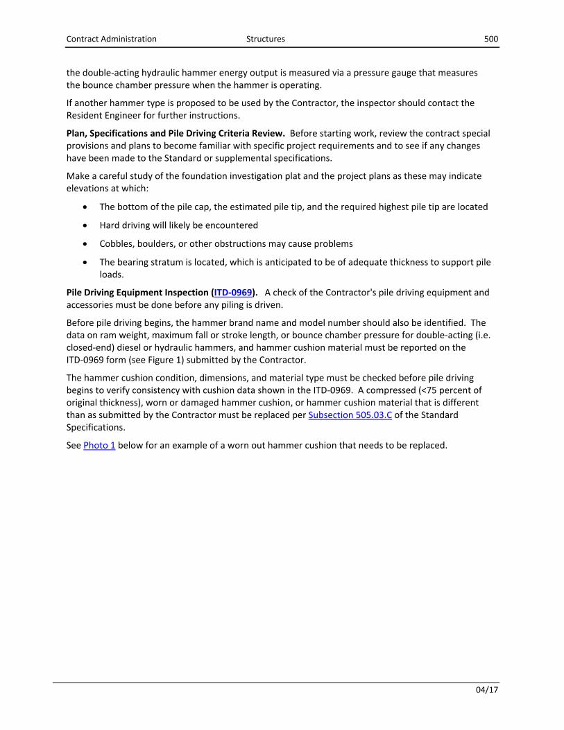
The hammer cushion condition, dimensions, and material type must be checked before pile driving begins to verify consistency with cushion data shown in the ITD‐0969. A compressed (<75 percent of original thickness), worn or damaged hammer cushion, or hammer cushion material that is different than as submitted by the Contractor must be replaced per Subsection 505.03.C of the Standard Specifications.
See Photo 1 below for an example of a worn out hammer cushion that needs to be replaced.
Contract Administration Structures 500
04/17
Photo 1. Worn out hammer cushion.
Any change in the hammer system may require a new wave equation analysis to be run. Notify the
Engineer immediately if the pile hammer system delivered to the site deviates in any way from what
was submitted for the wave equation analysis.
Safe pile driving operations require that equipment be in good condition and that workers are safety‐conscious. Cables, connections, and safe handling of the piling and the pile driving system should be observed. The inspector must be especially careful when making measurements in the area around pile driving operations. The operator and workers should be made aware of the inspector’s presence at all times.
Pile Splice Inspection. Refer to the plans and specifications to determine splice requirements.
Piling lengths exceeding 60 feet will likely require a splice. For piles that have not yet been driven, no more than two (2) splices will be allowed, and the minimum allowable pile splice section length will be 10 feet.
Pile splice welding must be done by welders certified as specified in the bridge plans. The project inspector should verify welder certification for the type of welding process and welding position proposed to be used before field welding begins.
Contract Administration Structures 500
04/17
Predrilling. Minimum pile penetration is often needed to help piles develop adequate lateral load resistance or to place the pile tip into a desired soil layer. It may be difficult to obtain this penetration when driving piles through rock fills, very dense sand and gravel formations, boulders, or certain silts. If refusal occurs before minimum penetration is obtained, the Contractor may be required to try a larger hammer size or pre‐drill the hole, depending on the contract requirements.
When pre‐drilling is employed, the borehole diameter and depth should be as shown in the project special provisions. The borehole diameter is often slightly larger than the pile diameter (or diagonal dimension for H piles). The borehole is often drilled to the highest pile tip elevation to ensure that the pile will have the required minimum penetration.
The piling must be impact driven to its final position and pile design capacity or refusal. Piles can be driven in empty or pre‐filled holes per the project plans or special provisions. The borehole annulus is often filled with pea gravel, sand and gravel or other approved materials. The borehole annulus extending into rock is sometimes grouted to the top of rock surface.
The pre‐drilling depth and diameter should be documented on the Test Pile Record (ITD‐0970) (see Figure 2) and Individual Pile Driving Record (ITD‐0971) (see Figure 3).
Pile Driving Inspection.
Material Inspection (including lifting holes). Do not allow the Contractor to drive piling until the materials acceptance requirements per the Quality Assurance Manual, Item 505 (Section 230), are accomplished for each piling type to be used.
Steel Pipe Piling: Check for wall thickness and outside and inside diameter. Check end closure diameters and thicknesses.
H‐Piling: Verify that the Contractor is handling the H piles in a manner that prevents bending of the flanges and that the piling is supported when stacked for storage to prevent damage. Check H piles for correct sectional dimensions, square ends, straightness, and constant width between flanges throughout the pile length.
Pile points or shoes may be needed to help piles penetrate hard soils or key into bedrock. Current Department‐approved products should be listed in the bridge plans or lists may be obtained from the State Geotechnical Engineer or the Department’s QPL website.
Conical points may also be specified for pipe piles that must be driven through dense or hard soils. If conical points are not specified (typically in soft or loose soils), steel pipe piles will often have a 1‐inch‐thick steel plate welded to close off the tip. The steel plate’s purpose is to keep soil and water out because the pile will be filled with concrete. Occasionally, pipe piles will be driven open ended as in the case where a layer of dense soil may prevent closed‐end piles to reach the required minimum penetration. Carefully review the contract plans and specifications for special instructions and details pertaining to this situation before pile driving operations begin.
An ITD‐0914, Steel Certification form should be obtained from the Contractor for all pile and accessory shipments, including certified mill test reports for all heat numbers per the QA Manual Subsection 230.03. The ITD‐0914s and required attachments should be placed into the project files. Pile and accessory shipments not accompanied by the required certifications are subject to rejection.
Contract Administration Structures 500
01/18
Site Preparation Inspection. Do not allow the Contractor to drive any piling until the foundation excavation (or embankment construction) is complete to bottom of pile cap elevation. When embankment settlement is expected where piles will be driven, pile driving should not start until at least 90 percent of the settlement, as determined by the Engineer, has been completed to avoid pile down‐drag loads caused by embankment settlement.
Saximeter Operation, ITD 0970 (Test Pile Record) and ITD‐0971 (Individual Pile Driving Record). The Saximeter (see Photo 2 below) is a hand‐held device that uses sound recognition to automatically detect hammer blows when the pile is struck. Background noise is managed through manual adjustment of the sound sensitivity level at which a blow is detected. During pile driving, when the pile has penetrated each depth increment (e.g. 1 foot or 1 inch) the inspector presses the “AVG” button. The Saximeter then displays the number of blows detected (e.g. blows per foot or inch) and the average hammer stroke during the preceding depth increment. This information is then transferred to the Test Pile Record (ITD‐0970) or the Individual Pile Driving Record (ITD‐0971). The information on hammer stroke and number of blows per pile penetration increment is used to determine the pile‐bearing capacity. Contact the District Materials Engineer if you need a Saximeter.
Photo 2. Typical Saximeter models used on ITD projects.
In the event that the Saximeter gives an average stroke and blow count reading that is erratic or does
not appear to match up with how the pile driving hammer is operating, the problem is most likely being
caused by the Saximeter recording background noise as additional blow counts. This will usually
manifest itself by an average stroke reading that is significantly less (and a blow count that is
significantly higher) than how the pile driving hammer is actually operating. The remedy for this
problem is to raise the Saximeter sensitivity threshold (i.e. reduce the sensitivity) so the saximeter does
not pick up background noise such as from heavy trucks, construction equipment or trains, and only
records the pile hammer blows.
Contract Administration Structures 500
04/17
In the event the Saximeter is not working, the following graph can be used to estimate the hammer
stroke from blows per minute.
Test Piles. Notify the Engineer of the date test piles are planned to be driven as early as possible, as well
as any test pile schedule changes, so the Engineer who provided the pile driving criteria can receive the
earliest possible notice to be available to analyze the test pile data and provide final pile lengths and
revised pile driving criteria if required. Since the specifications allow only two business days to analyze
the test pile data, the State Geotechnical Engineer (or the engineer who prepared the pile driving
criteria with the wave equation analysis) needs to know the test pile driving date as early as possible, so
that he/she can arrange his/her schedule and perform the test pile analysis within two business days
after test pile driving is completed.
The ITD‐0970, Test Pile Record form, is used for test piles.
Test pile data should be recorded from the beginning of test pile driving. If for any reason this is not
possible, start recording data as early as possible. Sufficient readings should be taken to permit plotting
a graph of bearing versus penetration from the beginning to the end of test pile driving. A separate
Contract Administration Structures 500
04/17
record is required for each test pile. Handwritten records, neatly prepared, are acceptable and
recopying is discouraged. The ground elevation at the test pile location must be recorded.
Test piles should be driven as continuously as possible, so the potential for soil set‐up (or freezing),
which could result in premature pile driving refusal or a false indication of pile‐bearing capacity, will be
reduced.
Other pile inspection procedures, as described below, for production piles should be followed for test
piles.
Test pile data on the ITD‐0970 form should be sent to the State Geotechnical Engineer (or the engineer
who prepared the pile driving criteria with the wave equation analysis) as soon as it is available. The
State Geotechnical Engineer (or the engineer who prepared the pile driving criteria) will analyze the test
pile results to verify the pile driving criteria and to determine the pile length needed for the footing
where the test pile was driven. The State Geotechnical Engineer (or the engineer who prepared the pile
driving criteria) will then advise the Resident Engineer on the pile length the Department should
authorize.
If test piles are not required, the Resident Engineer will base the authorized piling length on the
estimated pile lengths shown in the plans.
Pile Markings. All piles should be marked in increments (e.g. 1 foot or 1 inch) sufficient to determine bearing capacity and penetration at all elevations. It is also recommended that each 5‐foot increment from the pile tip be labeled for ease of recording pile penetration depths. Usually, a white or yellow keel or paint stick is satisfactory for marking the piling. On greasy, treated timber piling, spray paint generally gives the best results.
To observe pile penetration from one increment to the next, select a reference point so that it will be fixed, easy to see, and will not move during pile driving.
Determining Pile Bearing Capacity. A wave equation analysis is typically used for developing pile driving criteria that are needed for determining pile‐bearing capacity. Necessary data on pile driving equipment (ITD‐0969) must be submitted to the Resident Engineer and State Geotechnical Engineer (or the consultant engineer who will perform the wave equation analysis) at least 15 days in advance of pile driving so that the wave equation analysis can be performed. The wave equation analysis is used to determine the adequacy of the hammer system, prepare the pile driving criteria, and evaluate stroke, penetration resistance, bounce pressure, and driving stresses. If the proposed hammer is judged to be not adequate for the job, the Resident Engineer will require the Contractor to use a different hammer. The Contractor should be requested to provide the completed ITD‐0969 form at the preconstruction conference.
If pile driving criteria developed by wave equation analysis is not available, then the Engineer should
use the dynamic formula in the Standard Specifications, Subsection 505.03.G, to determine pile‐
bearing capacity during driving. However, in this case the Engineer who designed the structure must
be informed as soon as possible of the use of the dynamic formula so that he/she can adjust the
minimum bearing capacity that piles will have to be driven to.
Usually the State Geotechnical Engineer prepares and forwards the pile driving criteria developed by
wave equation analysis to the Resident Engineer. However, the pile driving criteria is sometimes
Contract Administration Structures 500
04/17
prepared by consultants. The pile driving criteria typically includes the required minimum blow counts
for given stroke heights to achieve the design pile‐bearing capacities. It also includes a graph showing
pile capacity versus blow count per last 1 foot and/or 1 inch of driving (see example pile driving criteria
and graph presented in Figure 6 below). This graph will generally show curves for different hammer
stroke heights. Graphs may be prepared for various pile lengths, since the Wave Equation is based on
definite pile lengths for bearing computations. Use the graph that corresponds to the actual piling
length being driven if there are different graphs for different pile lengths.
A graph may also be provided showing stresses induced in the piles during driving versus stroke or blow
counts. This graph can be used to determine the maximum stroke or blow count that should not be
exceeded to prevent pile damage. This information is typically included with the recommended pile
driving criteria presented in the below described cover letter.
The required penetration resistance, defined by blow counts for refusal or for the required pile capacity,
will be shown in the cover letter, (see the example presented in Figure 6 at the end of this section). The
pile refusal criteria are established to minimize potential for pile damage, particularly where piles are
driven into rock. The inspector must compare the number of blows during the last 1 foot or 1 inch of
driving with the required blow counts to determine if the required pile‐bearing capacity or refusal has
been achieved.
The required pile capacity should be achieved in at least two consecutive 1‐foot or 1‐inch penetration
intervals before driving can be stopped. When piles are driven to refusal or in very hard or dense
materials, the blow counts could be very high, and in these cases blow counts per 1‐inch intervals
instead of per 1‐foot intervals can be used to determine pile bearing. If the wave equation analysis
indicates that a pile might be overstressed and damaged at a certain blow count and/or stroke, this level
of driving resistance will be indicated in the cover letter, and must never be exceeded.
The stroke height must be adjusted to compensate for the increased ram friction and inclination for
battered piles. A stroke height adjustment graph is generally found in the Saximeter operating manual.
Additionally, the pile driving criteria will be adjusted for pile batter, and the adjustment noted in the
cover letter.
Notify the Resident Engineer as soon as possible when any driven pile does not achieve the required
minimum penetration (or highest tip elevation), or does not achieve the required pile bearing at a
penetration of less than 150 percent of the estimated pile length shown in the plans. Adjustments may
be needed in the pile driving criteria.
Pile Stresses. Any driven pile must remain structurally intact and not be stressed to its structural limits
during both its service life (static capacity) and during driving (dynamic capacity). In most cases, the
highest stress levels will occur during driving. Therefore, pile damage often occurs because of excessive
stress levels generated in the pile during driving. Two methods available for determining driving
stresses are (1) a wave equation analysis, and (2) use of a dynamic Pile Driving Analyzer (PDA) during pile
driving.
In easy driving situations (low resistance to pile driving), high tensile stresses are generated. Make sure
that the tensile driving stress limitation is not exceeded. Typical easy driving situations are (1) at the
Contract Administration Structures 500
04/17
beginning of driving, and (2) when the pile penetrates into soft or loose soil layers which offer little
resistance to the pile tip.
In hard driving situations (high resistance to pile driving), high compressive stresses will be generated.
Make sure that the compressive driving stress limitation is not exceeded. Typical hard driving situations
are (1) at the end of driving for end‐bearing piles, and (2) when the pile penetrates into very dense soil
or rock layers. If pile driving becomes difficult and refusal is met before the required highest tip
elevation is obtained, pile driving should be stopped and the Resident Engineer should be consulted.
Otherwise, piling may be damaged.
The pile driving criteria developed using the wave equation analysis method, as described above under
Determining Pile‐Bearing Capacity, are designed to minimize the potential for pile damage due to
overstressing the pile during pile driving. Therefore, the maximum pile hammer stroke presented with
the pile driving criteria should never be exceeded.
The dynamic pile test, using a Pile Driving Analyzer (PDA) (see discussion below), is typically used for
monitoring the test pile driving (and occasionally used for monitoring production pile driving). The
dynamic pile test can measure the actual driving stresses for each hammer blow and the static pile
capacity during driving. The dynamic pile test can detect potential pile damage during driving.
Production Pile Driving. Vibratory hammers can be used, if approved by the Engineer, to drive piles but
must be stopped at least 10 feet above the estimated pile tip elevation as shown on the plans, or as
directed. An impact hammer must then be used to drive piles to the required tip elevation or to the
required pile bearing.
Verify the Contractor is driving the piles at the locations as shown in the plans and at the correct pile
spacing. Check the vertical alignment (plumb or batter) and the location of each pile during installation.
During construction, the Contractor must drive piles with a variation in alignment of not more than 0.25
in/ft from the vertical (or from the batter shown in the plans). The pile top plan location, at cutoff
elevation, cannot deviate by more than 6 inches (2 inches for trestle bents) in any direction from the
location shown in the plans. For steel H piles, pile orientation is important because the lateral resistance
to pile bending depends on the web direction. Check the H pile orientation to ensure that rotational
deviation is not more than 15 degrees from that shown in the plans. Notify the Resident Engineer if any
driven pile becomes damaged or does not meet the above criteria, so that a determination can be made
for any necessary corrective actions.
During driving, the average stroke height and number of blows per foot or inch for open‐ended diesel or
single‐acting hydraulic hammers is determined using a Saximeter that records the hammer blows
acoustically as described above under Saximeter Operation. The average stroke height and number of
blows per foot or inch (for the last foot or inch of driving) are then compared with the pile driving
criteria to determine if the pile has been driven to the required minimum bearing capacity as described
under Determining Pile‐Bearing Capacity above. If the number of blows per foot or inch meets or
exceeds the minimum required for the measured average stroke height, the pile has been driven to the
required minimum capacity. It may be possible, but highly unlikely, that a contractor may want to use a
Contract Administration Structures 500
04/17
closed‐end, diesel, or hydraulic hammer. In this case, contact the State Geotechnical Engineer for test
and production pile driving guidance.
The Contractor is required to drive piles to the required minimum bearing capacity or refusal, as
described in Pile Driving Criteria and highest tip elevation or minimum penetration, as specified in the
bridge plans and Standard Specifications Subsection 505.03.A, respectively. However, care is needed to
prevent piles driven to end bearing on rock or piles that encounter boulders from being damaged by
overdriving as shown in Photo 3 below.
Photo 3. Damaged H pile due to overdriving.
Occasionally, when piles are driven to refusal on a sloping rock surface, or when a large obstruction,
such as boulder, is encountered, the pile may refuse momentarily (or driving resistance may
momentarily spike) then bend and take off down the slope (see Photo 4 below). An alert inspector who
has studied the Foundation Investigation Plat sheet, and has familiarized themself with the anticipated
subsurface conditions will often be able to detect this and stop the pile driving operation the moment
this occurs.
Contract Administration Structures 500
04/17
Photo 4. Pipe pile damaged on sloping rock surface, in the process of being extracted.
Pile damage can be detected during driving when monitored by dynamic pile testing. After driving, steel
pipe piles should be checked for damage that may have occurred during driving. This can be done by
either lowering a light to the bottom of the pipe or using a mirror to reflect sunlight into the pile
interior. Pipe piles should be covered after driving as a safety measure and to keep out water and
debris. Piles that contain water must either be pumped or bailed out just prior to placing concrete, or
the concrete must be placed under the water by an approved (e.g., tremie) method.
Make sure all piles in a given substructure have been satisfactorily driven or re‐driven if heaving (pile
being pushed up due to the driving of adjacent piles) has occurred before the piles are accepted for that
substructure. Do not delay the Contractor unnecessarily, but inspectors should not let the Contractor
pressure them into making a premature determination.
Use the ITD‐0971, Individual Pile Driving Record form to record data for each production pile driven.
Documenting actual pile driving time in the pile driving records (or the inspector’s diary) may discourage
contractors from claiming the inspector is requiring overdriving. The Contractor is less likely to use this
as an excuse for a slow operation if the records will show otherwise. Also, pile driving time records
could be very helpful in determining unit price adjustments in the event differing site conditions are
encountered (or claimed).
Piles should be cut off perpendicular to the pile axis after driving has been completed and the piles are
accepted. Rejected H piles should be removed or cut off 2 feet below bottom of footing.
Contract Administration Structures 500
04/17
Rejected pipe piles should be cut off 2 feet below bottom of footing, left in place and filled with pea
gravel.
Pile Restrike. Some soil types such as silts and clays will readjust after pile driving has stopped. This will
often result in an increased pile‐bearing capacity referred to as soil set‐up (or freezing). This pile‐
bearing capacity increase can be as much as 50 percent or more in as little as 24 hours. Some soils, such
as very dense, saturated sand, may relax after pile driving is finished and cause the pile to lose capacity
over time. However, this condition, called soil relaxation, seldom happens.
Occasionally, piles may need to be re‐driven a short distance after a waiting period specified in the
contract or as directed by the Resident Engineer to determine whether pile‐bearing capacity has
increased due to soil set‐up or decreased due to soil relaxation.
Pile re‐strikes should only be done with a pile hammer that has been warmed up to normal operating
temperature. Hammer warm‐up can be accomplished by striking about 20 blows or more on another
pile located as far away from where the re‐strike will be performed as practical.
After the hammer is warmed up, the hammer is placed on the pile to be re‐struck and the pile driven for
at least four inches. The inspector logs the number of blows per inch and stroke for each of the four‐
inch increments driven. This data is then reported to the Engineer for evaluation to estimate what, if
any, soil set‐up or relaxation has occurred. If the pile dynamic test is performed for a test pile during
initial driving, it is very likely that a pile dynamic test will also be required on the same pile during re‐
striking.
The re‐strike test results may be used by the Engineer to develop revised pile driving criteria that will
account for anticipated soil set‐up or relaxation.
Pile Heaving. In loose silt and soft clay, pile heaving may occur when adjacent piles are driven. For this
reason, the inspector should check elevations on pile groups after they are driven. Any piles that have
heaved more than ¼ inch must be re‐driven to the required pile capacity before the piling group is
accepted.
Documentation. Use the ITD‐0025 Construction Diary form to document the activity, date, and location of the work.
Measure and report piling quantities to the nearest 1 foot.
Pay Quantities (ITD‐0972) (see Figure 4)
The ITD‐0972, Summary Report of Pile Driving form, shall be the source document for pay quantities.
Pile Layout (ITD‐0973) (see Figure 5)
The ITD‐0973, Pile Driving Summary Report (Pile Layout) form, shows the driven pile locations relative to the pile cap (footing) or hammer head centerline.
Examples of these forms are presented below.
Contract Administration Structures 500
04/17
Pile Hammer Performance Issues. If the pile hammer is not operating properly, the pile‐bearing capacity cannot be accurately determined. Some common pile hammer performance issues are described below.
A common diesel hammer performance problem is called pre‐ignition. Pre‐ignition occurs when fuel ignites before the ram strikes the anvil (or impact block). Pre‐ignition reduces ram impact velocity and cushions the impact. Pre‐ignition also causes the stroke and blow count to appear to be high, and thus gives a false indication of the true pile‐bearing capacity. Pile hammer overheating is one reason for pre‐ignition.
The following are signs of pre‐ignition during hard driving:
Black smoke combined with high strokes.
Flames in exhaust ports.
Blistering paint on pile hammer due to excessive heat.
No obvious metal‐to‐metal impact (clang) sound.
If pre‐ignition is suspected, the hammer should be stopped and allowed to cool down. If stroke and blow counts are significantly lower after cool down, pre‐ignition was most likely occurring.
Other pile hammer operating issues and associated symptoms are:
Water in the fuel. Causes white exhaust smoke and a hollow sound on impact.
Clogged fuel lines. Indicated by little or no exhaust smoke.
Malfunctioning fuel pump. Indicated by inconsistent ram strokes and gray or black exhaust
smoke.
Malfunctioning fuel injectors. Indicated by inconsistent ram strokes and gray or black
exhaust smoke.
Low lubricating oil. Indicated by shorter than normal stroke.
Malfunctioning oil pump. Indicated by shorter than normal stroke.
Water in the combustion chamber. Causes white exhaust smoke and a hollow sound on impact.
Worn piston rings. Indicated by shorter than normal stroke.
Broken tripping device. Pawl or pin used to lift ram does not engage ram. Pawl engages but
does not lift ram.
Overheating. See discussion above on pre‐ignition.
Many diesel hammers have multiple fuel settings that can be used to adjust the fuel amount going into the combustion chamber and thus reduce or increase the delivered hammer energy.
Contract Administration Structures 500
04/17
Dynamic Pile Testing. Dynamic pile testing is performed using a Pile Driving Analyzer (PDA), which is a
device used to measure and analyze the hammer’s effect on the pile and calculate bearing capacity.
Specifically, the PDA can provide output that shows unit skin friction per foot of pile length, bearing
capacity at the pile tip, maximum compressive and tensile stress per foot increment of pile, and indicate
the depth(s) along the pile length where damage may have occurred during pile driving. The PDA output
can also be used to fine‐tune the wave equation analysis to optimize/confirm pile driving criteria.
To perform the test, two transducers are bolted to an exposed portion of the pile (see Photo 5 of
transducers below) that measure strain and acceleration during pile driving. With the newer PDAs, the
strain and acceleration data is wirelessly transmitted to the PDA for analysis. This data can even now be
sent directly to the Engineer for analysis at a remote office in real time via cell phone and the internet.
Photo 5. PDA transducers attached to pile.
Pile Inspector’s Checklist.
1. Before starting work, review the contract special provisions and plans to see if any changes have been made to the Standard or supplemental specifications. Make sure the Saximeter is working properly and that all inspectors are familiar with its operation. Have all the necessary forms available for recording pile driving data.
2. Perform pile and pile accessory (e.g., pile points or shoes) material inspection, including obtaining materials certifications (ITD‐0914), verifying domestic production, and matching heat numbers with markings on the piling. All sectional dimensions should be checked, including wall thickness for pipe piles to verify the required sizes have been delivered to the site. Weld
Contract Administration Structures 500
04/17
quality should also be inspected. Pile accessories should only be approved products as presented in the bridge plans or on the QPL website.
3. Verify that the pile hammer delivered to the site is the same make and model as was proposed in the ITD‐0969 form.
4. Verify the pile hammer cushion is the same material type and dimensions as was submitted by the Contractor on the ITD‐0969. The hammer cushion should be periodically inspected and replaced as required in Subsection 505.03.C of the Standard Specifications.
5. Become familiar with pressure gauge operation and readings, and how to properly interpret the pile driving criteria for double‐acting or hydraulic hammers.
6. Check pile storage to verify piles are properly supported off the ground and separated by wooden blocking to prevent damage and to prevent contact with dirt, water, and other foreign material.
7. Verify welders performing onsite welding are certified for the welding applications/positions they are performing.
8. Make sure footing excavations (or embankment construction) have been completed to bottom of footing elevation and predrilling, if required, has been performed to the required depth before pile driving begins.
9. Make sure test piles are located as depicted in the plans. The test pile location can be changed if approved by the Engineer.
10. Verify the helmet is properly positioned over the pile head, the pile is properly positioned, including orientation and verticality (or batter) before (test or production) pile driving begins. A pile can be easily damaged when not properly aligned with the hammer.
11. Observe the pile and its verticality (batter) as driving begins. Insist on immediate correction if orientation is wrong or if the pile moves out of position.
12. Verify piles are driven to the highest tip elevation or minimum penetration and required minimum bearing capacity (or refusal), as described in the bridge plans and pile driving criteria. Piles must be driven to the highest tip elevation even if they achieve the minimum capacity before pile tips reach that elevation. Once below this highest tip elevation, the driving can be stopped if the pile has also reached the minimum bearing capacity. However, if pile driving refusal is encountered before the pile tip reaches the required highest tip elevation, the pile driving must be stopped. Notify the Engineer of this situation as soon as possible.
13. Signal the pile driving foreman when the pile has reached the required bearing capacity or refusal.
14. Verify that heaved piles are re‐driven before allowing the Contractor to cut off piles.
15. Verify pile verticality (or batter), H pile orientation, and pile head location are within required tolerances per Standard Specifications Subsection 505.03.N. Document final pile layout on the ITD‐0973 form for each substructure.
16. Verify pipe piles are undamaged and water or debris (e.g., soil) has been removed before allowing concreting to begin.
Contract Administration Structures 500
04/17
17. Measure pile penetration from the bottom of footing (or seal concrete) elevation for pile caps or bottom of river or lake bed elevation for trestle bents.
18. Completely and legibly fill out the Test Pile Record (ITD‐0970), Individual Pile Driving Record (ITD‐0971), and Pile Driving Summary Report (ITD‐0972), so pay quantities can be accurately documented. Note that the pile tip protector is not included in pile length to be paid.
19. Verify soil that may have swelled above the bottom of pile cap elevation has been removed before reinforcing bar placement begins.
20. Contact the Engineer immediately if obstructions are encountered that cannot be penetrated (or removed if close to the ground surface).
Contract Administration Structures 500
04/17
Figure 1
Contract Administration Structures 500
04/17
Figure 2
Contract Administration Structures 500
04/17
Figure 3
Contract Administration Structures 500
04/17
Figure 4
Contract Administration Structures 500
04/17
Figure 5
Contract Administration Structures 500
04/17
ITD 0500 (Rev.10-07) Department Memorandum Idaho Transportation Department
DATE: DECEMBER 6, 2016 Program Number(s) A012(345)
TO: GEOFF EMERICK, P.E. RESIDENT ENGR.
Key Number(s) 12345
FROM: JOHN INGRAM, P.E., CONSTRUCTION/MATERIALS
Program ID, County, Etc. US-40, BIG RIVER BR, BLAINE CO
RE: ABUTMENT PRODUCTION PILE DRIVING CRITERIA
Following are abutment production pile driving criteria for the US-40 Concrete Girder Bridge over the Big River per your request. The criteria were developed using the Wave Equation analysis method as confirmed by a CAPWAP analysis, and assuming that an APE D30-32 open end, diesel hammer will be used to drive steel HP 14x117 Piles through medium dense to dense, gravel with cobbles into low strength, sedimentary rock. All piles are designed for a minimum bearing capacity of 375 kips.
The following blow count criteria are for a minimum bearing capacity of 375 kips per pile.
Attached is the graph showing the Abutment production pile Wave Equation analysis results. The Abutment 1 test pile achieved the minimum bearing capacity at an actual penetration of about 26 feet. Therefore, abutment production piles are estimated to have a pile length of 30 feet. Please call me at 334-8436 (or Tri at 334-8448 or 297-8379) if you have any questions. cc: Bridge Design-George Martin Dist. 4 Matls. Geotech Engr.
Contract Administration Structures 500
04/17
0
20
40
60
80
100
120
140
160
200 300 400 500 600 700 800
BLO
W/LAST FOOT OF DRIVING
PILE BEARING CAPCITY, KIPS
PILE BEARING CAPACITY vs BLOW COUNT US‐40, BIG RIVER BRIDGE‐ ABUTMENT PRODUCTION PILES