Section 6 - Storage 90-899883179 OCTOBER 2007 Page 83 Section 6 - Storage Table of Contents Cold Weather or Extended Storage.................... 84 Preparing Power Package for Storage.......... 84 Engine and Fuel System Preparation .... 85 Draining the Seawater System........................... 86 Drain System Identification........................... 87 Air Actuated Single Point Drain System ............................................................... 87 Manual Single Point Drain System ......... 87 Three Point Manual Drain System ......... 88 Multi-Point Drain (MPD) System ............ 88 Air-Actuated Single-Point Drain System....... 89 Boat in the Water ................................... 89 Boat out of the Water ............................. 91 Manual Single-Point Drain System............... 93 Boat in the Water ................................... 93 Boat out of the Water ............................. 94 Three-Point Manual Drain System................ 95 Boat in the Water ................................... 95 Boat out of the Water ............................. 97 Multi-Point Drain (MPD) System................... 97 Boat out of the Water ............................. 97 Boat in the Water ................................... 99 Draining the Sterndrive..................................... 101 Battery Storage................................................. 102 Power Package Recommissioning................... 102 6
Transcript
Section 6 - Storage
90-899883179 OCTOBER 2007 Page 83
Section 6 - StorageTable of ContentsCold Weather or Extended Storage.................... 84
Preparing Power Package for Storage..........84Engine and Fuel System Preparation ... . 85
Draining the Seawater System........................... 86Drain System Identification...........................87
Air Actuated Single Point Drain System............................................................... 87Manual Single Point Drain System ......... 87Three Point Manual Drain System ......... 88Multi-Point Drain (MPD) System ............ 88
Air-Actuated Single-Point Drain System.......89Boat in the Water ................................... 89Boat out of the Water ............................. 91
Manual Single-Point Drain System...............93Boat in the Water ................................... 93Boat out of the Water ............................. 94
Three-Point Manual Drain System................95Boat in the Water ................................... 95Boat out of the Water ............................. 97
Multi-Point Drain (MPD) System...................97Boat out of the Water ............................. 97Boat in the Water ................................... 99
Draining the Sterndrive..................................... 101Battery Storage................................................. 102Power Package Recommissioning................... 102
6
Section 6 - Storage
Page 84 90-899883179 OCTOBER 2007
Cold Weather or Extended StorageIMPORTANT: Mercury MerCruiser strongly recommends that this service should beperformed by an authorized Mercury MerCruiser dealer. Damage caused by freezingtemperatures IS NOT covered by the Mercury MerCruiser Limited Warranty.
NOTICEWater trapped in the seawater section of the cooling system can cause corrosion orfreeze damage. Drain the seawater section of the cooling system immediately afteroperation or before any length of storage in cold weather. If the boat is in the water, keepthe seacock closed until restarting the engine to prevent water from flowing back into thecooling system. If the boat is not fitted with a seacock, leave the water inlet hosedisconnected and plugged.
NOTE: As a precautionary measure, attach a tag to the key switch or steering wheel of theboat reminding the operator to open the seacock or unplug and reconnect the water inlethose before starting the engine.IMPORTANT: Mercury MerCruiser requires that propylene glycol antifreeze, mixed to themanufacturers instructions, be used in the seawater section of the cooling system forfreezing temperatures or extended storage. Make sure that the propylene glycol antifreezecontains a rust inhibitor and is recommended for use in marine engines. Be certain to followthe propylene glycol manufacturer's recommendations.
Preparing Power Package for Storage1. Fill the fuel tanks with fresh gasoline (that does not contain alcohol) and a sufficient
amount of Quicksilver Gasoline Stabilizer for Marine Engines to treat the gasoline.Follow instructions on the container.
2. If the boat is to be placed in storage with fuel containing alcohol in fuel tanks (if fuelwithout alcohol is not available): Fuel tanks should be drained as low as possible andMercury/Quicksilver Gasoline Stabilizer for Marine Engines added to any fuelremaining in the tank. Refer to Fuel Requirements for additional information.
3. Flush the cooling system. Refer to the Maintenance section.IMPORTANT: In order to run the engine as required in the remainder of the storagepreparation procedure, water must be supplied to the engine as described in the flushingprocedure.4. Provide cooling water to the engine as done in the previous step.5. Operate the engine sufficiently to bring it up to normal operating temperature and allow
fuel with Mercury/Quicksilver Gasoline Stabilizer to circulate through the fuel system.Shut off the engine.
6. Change the oil and oil filter.7. Prepare the engine and fuel system for storage. Refer to Engine and Fuel System
Preparation.8. Drain the engine seawater cooling system. Refer to Draining the Seawater System.
Section 6 - Storage
90-899883179 OCTOBER 2007 Page 85
NOTICEWater trapped in the seawater section of the cooling system can cause corrosion orfreeze damage. Drain the seawater section of the cooling system immediately afteroperation or before any length of storage in cold weather. If the boat is in the water, keepthe seacock closed until restarting the engine to prevent water from flowing back into thecooling system. If the boat is not fitted with a seacock, leave the water inlet hosedisconnected and plugged.
9. Ensure that the sterndrive vent holes and water drain holes and passages areunobstructed and open (refer to Draining Instructions).
10. For additional assurance against freezing and rust, after draining, fill the cooling systemwith propylene glycol mixed to the manufacturer's recommendation to protect engineto the lowest temperature to which it will be exposed during freezing temperatures orextended storage.
NOTICEThe universal joint bellows may develop a set when stored in a raised or up position,causing the bellows to fail when returned to service and allowing water to enter the boat.Store the sterndrive in the full down position.
11. Store boat with drive unit in full down/in position.12. Store the battery according to the manufacturer's instructions.
ENGINE AND FUEL SYSTEM PREPARATION
! WARNINGFuel is flammable and explosive. Ensure the key switch is off and the lanyard is positionedso that the engine cannot start. Do not smoke or allow sources of spark or open flame inthe area while servicing. Keep the work area well ventilated and avoid prolongedexposure to vapors. Always check for leaks before attempting to start the engine andwipe up any spilled fuel immediately.
! WARNINGFuel vapors trapped in the engine compartment may be an irritant, cause difficultybreathing, or may ignite resulting in a fire or explosion. Always ventilate the enginecompartment before servicing the power package.
1. Prepare carbureted fuel system for extended storage as follows:a. Start engine.b. Provide cooling water to the engine as done in the previous step.c. Remove flame arrestor assembly.d. Close the fuel shut off valve, if equipped. Disconnect and plug the fuel inlet fitting
if not equipped with a fuel shut off valve.e. While operating engine at fast idle (1300 RPM), fog internal surfaces of induction
system and combustion changers by spraying approximately 227 g (8 oz.) ofMercury/Quicksilver Storage Seal or SAE 20W engine oil into carburetor bores.
f. Spray the remaining 57 g (2 oz.) of Storage Seal (or oil) rapidly into carburetor,just as the engine begins to stall, due to lack of fuel. Allow engine to stop.
Section 6 - Storage
Page 86 90-899883179 OCTOBER 2007
Tube Ref No. Description Where Used Part No.
119 Storage Seal Rust Inhibitor Carburetor 92-858081K01
g. Turn ignition key to "OFF" position.2. Refer to Flushing the Power Package and appropriately remove the water supply the
the seawater pickup pump.3. Clean the flame arrestor and crankcase ventilation hoses and reinstall.4. Lubricate all items listed in the Lubrication section.5. On models with closed cooling systems: Test coolant to ensure that it will withstand the
lowest temperature expected during storage.6. Service batteries according to the manufacturer's instructions.7. Clean the outside of the engine and repaint any areas required with Mercury/
Quicksilver Light Gray Primer and Phantom Black Paint. After paint has dried, wipedown the outside of the engine with Corrosion Guard.
Tube Ref No. Description Where Used Part No.
120 Corrosion Guard Outside of engine 92-802878 55
8. For sterndrive unit lay‑up, refer to appropriate Mercury MerCruiser sterndrive servicemanual.
9. Replace the fuel filter. Refer to the Maintenance section for proper procedure.10. Change the oil and oil filter.
Draining the Seawater System! CAUTION
Water can enter the bilge when the drain system is open, damaging the engine or causingthe boat to sink. Remove the boat from the water or close the seacock, disconnect andplug the seawater inlet hose, and ensure the bilge pump is operational before draining.Do not operate the engine with the drain system open.
IMPORTANT: Only drain the seawater section of the closed‑cooling system.IMPORTANT: The boat must be as level as possible to ensure complete draining of thecooling system.Your power package is equipped with a drain system. Refer to Drain SystemIdentification to determine which instructions apply to your power package.IMPORTANT: The engine must not be operating at any point during the draining procedure.IMPORTANT: Mercury MerCruiser requires that propylene glycol antifreeze, mixed to themanufacturer's instructions, be used in the seawater section of the cooling system forfreezing temperatures or extended storage. Make sure that the propylene glycol antifreezecontains a rust inhibitor and is recommended for use in marine engines. Be certain to followthe propylene glycol manufacturer's recommendations.
Section 6 - Storage
90-899883179 OCTOBER 2007 Page 87
Drain System IdentificationAIR ACTUATED SINGLE POINT DRAIN SYSTEM
6124
a bc
d6125
a
b
c
d
Closed Cooled Models Seawater Cooled Modelsa - Blue drain plug locationb - Blue air pump
c - Air manifoldd - Green indicators
21125
ab
c
d
d
Scorpion Modelsa - Blue air pumpb - Air manifold
c - Green indicatorsd - Blue drain plug locations
MANUAL SINGLE POINT DRAIN SYSTEM
b
a
b
6128
a - Blue handle b - Blue drain plug location
Section 6 - Storage
Page 88 90-899883179 OCTOBER 2007
THREE POINT MANUAL DRAIN SYSTEM
a a6126
a - Blue drain plug
MULTI-POINT DRAIN (MPD) SYSTEM
10226 M110050
93235672
b
aa
b
6129
a - Side of cylinder block b - Bottom of exhaust manifolds
ab
6130
a - Water circulating pump hose b - Fuel cooler to thermostat housing
Section 6 - Storage
90-899883179 OCTOBER 2007 Page 89
a
6131
a - Check valve (if equipped)
Air‑Actuated Single‑Point Drain SystemBOAT IN THE WATER
NOTE: This procedure is written for the air pump that is attached to the engine. However,any air source can be used.1. Close the seacock (if equipped) or remove and plug the water inlet hose.2. Remove the air pump from the engine.3. Ensure that the lever on top of the pump is flush with the handle (horizontal).4. Install the air pump on the actuator fitting.5. Pull lever on air pump (vertical) to lock pump on the fitting.
8293b
d
e
a
c
a - Actuator fittingb - Green indicatorsc - Manual release valve
d - Air pumpe - Lever (locking)
6. Pump air into the system until both green indicators extend and water drains from bothsides of the engine. The port side will begin draining before the starboard side.
Section 6 - Storage
Page 90 90-899883179 OCTOBER 2007
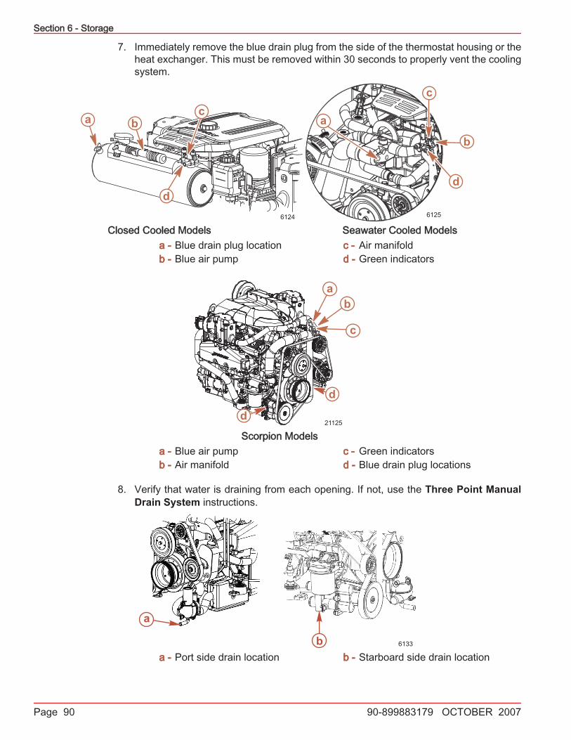
7. Immediately remove the blue drain plug from the side of the thermostat housing or theheat exchanger. This must be removed within 30 seconds to properly vent the coolingsystem.
6124
a bc
d6125
a
b
c
d
Closed Cooled Models Seawater Cooled Modelsa - Blue drain plug locationb - Blue air pump
c - Air manifoldd - Green indicators
21125
ab
c
d
d
Scorpion Modelsa - Blue air pumpb - Air manifold
c - Green indicatorsd - Blue drain plug locations
8. Verify that water is draining from each opening. If not, use the Three Point ManualDrain System instructions.
a
b 6133
a - Port side drain location b - Starboard side drain location
Section 6 - Storage
90-899883179 OCTOBER 2007 Page 91
9. Allow the system to drain for a minimum of five minutes. Pump air as necessary to keepthe green indicators extended.
10. Crank the engine over slightly with the starter motor to purge any water trapped in theseawater pump. Do not allow engine to start.
11. Reinstall the blue drain plug in the thermostat housing or heat exchanger.12. Remove the air pump from the air manifold and return it to the mounting bracket.13. Mercury MerCruiser recommends leaving the drain system open while transporting the
boat or while performing other maintenance. This helps ensure that all water is drained.14. Before launching the boat, pull up on the manual release valve. Verify that the green
indicators are no longer extended.
a6135
a - Green indicators
15. Open the seacock, if equipped, or unplug and reconnect the water inlet hose prior tooperating the engine.
BOAT OUT OF THE WATERNOTE: This procedure is written for the air pump that is attached to the engine. However,any air source can be used.1. Place the boat on a lever surface to ensure complete draining of system.2. Remove the air pump from the engine.3. Ensure that the lever on top of the pump is flush with the handle (horizontal).4. Install the air pump on the actuator fitting.
Section 6 - Storage
Page 92 90-899883179 OCTOBER 2007
5. Pull lever on air pump (vertical) to lock pump on the fitting.
8293b
d
e
a
c
a - Actuator fittingb - Green indicatorsc - Manual release valve
d - Air pumpe - Lever (locking)
6. Pump air into the system until both green indicators extend and water drains from bothsides of the engine. The port side will begin draining before the starboard side.
6124
a bc
d6125
a
b
c
d
Closed Cooled Models Seawater Cooled Modelsa - Blue drain plug locationb - Blue air pump
c - Air manifoldd - Green indicators
21125
ab
c
d
d
Scorpion Modelsa - Blue air pumpb - Air manifold
c - Green indicatorsd - Blue drain plug locations
Section 6 - Storage
90-899883179 OCTOBER 2007 Page 93
7. Verify that water is draining from each opening. If not, use the Three Point ManualDrain System instructions.
a
b 6133
a - Port side drain location b - Starboard side drain location
8. Allow the system to drain for a minimum of five minutes. Pump air as necessary to keepthe green indicators extended.
9. Crank the engine over slightly with starter motor to purge any water trapped in theseawater pump. Do not allow engine to start.
10. Remove the air pump from the air manifold and return it to the mounting bracket.11. Mercury MerCruiser recommends leaving the drain system open while transporting the
boat or while performing other maintenance. This helps ensure that all water is drained.12. Before launching the boat, pull up on the manual release valve. Verify that the green
indicators are no longer extended.
a6135
a - Green indicators
Manual Single‑Point Drain SystemBOAT IN THE WATER
1. Close the seacock (if equipped) or remove and plug the water inlet hose.2. Rotate the blue handle counterclockwise until it stops (approximately two turns). The
red on the handle shaft indicates that the drain system is open. Do not force the handleas this will create new threads.
Section 6 - Storage
Page 94 90-899883179 OCTOBER 2007
3. Immediately remove the blue drain plug from the side of the thermostat housing. Thismust be removed within 30 seconds to properly vent the cooling system.
a
b
6136
a - Blue handle b - Blue drain plug location
4. Visually verify that water is draining. If water does not drain, remove the blue drain plugfrom the distribution housing and drain manually.
a
b6137
a - Drain location ‑ orange or red b - Blue drain plug
5. Allow the system to drain for a minimum of five minutes. We recommend leaving thedrain system open while transporting the boat or performing other maintenance.
6. Reinstall the blue drain plug in the thermostat housing.7. Close the drain system by rotating the blue handle clockwise until it stops and install
the blue drain plug, if removed. The handle is fully seated when no red is visible. Donot overtighten the handle, as this action will create new threads.
8. Open the seacock (if equipped) or unplug and reconnect the water inlet hose beforeoperating the engine.
BOAT OUT OF THE WATER1. Place the boat on a level surface to ensure complete draining of system.
Section 6 - Storage
90-899883179 OCTOBER 2007 Page 95
2. Rotate the blue handle counterclockwise until it stops (approximately two turns). Thered on the handle shaft indicates that the drain system is open. Do not overtighten thehandle, as this action will create new threads.
a
6141
a - Blue handle
3. Visually verify that water is draining. If water does not drain, remove the blue drain plugfrom the distribution housing and drain manually.
a
b6137
a - Drain location ‑ orange or red b - Blue drain plug
4. Allow the system to drain for a minimum of five minutes. We recommend leaving theplugs out while transporting the boat or performing other maintenance to ensure thatall water is drained.
5. Close the drain system by rotating the blue handle clockwise until it stops or installingthe blue drain plug. The handle is fully seated when no red is visible. Do not overtightenhandle, as this action will create new threads.
Three‑Point Manual Drain SystemBOAT IN THE WATER
NOTE: Use this procedure if your engine is not equipped with an air‑actuated single‑pointdrain system or if the air‑actuated single point drain system fails.1. Close the seacock (if equipped) or remove and plug the water inlet hose.
Section 6 - Storage
Page 96 90-899883179 OCTOBER 2007
2. Remove the blue drain plug from the distribution housing (lower front, port side).
6138
a
a - Blue drain plug
3. To properly vent the cooling system, remove the blue drain plug from the side of thethermostat housing within 30 seconds.
a
6139
a - Blue drain plug location
4. Remove the two blue drain plugs from the seawater pickup pump (front, starboard side).
a 6140
a - Blue drain plugs
5. Verify that water is draining from each opening.6. Allow the system to drain for a minimum of five minutes. We recommend leaving the
drain system open while transporting the boat or performing other maintenance toensure that all water is drained.
7. Crank the engine over slightly with starter motor to purge any water trapped in theseawater pickup pump. Do not allow the engine to start.
8. Before launching the boat or starting the engine, close the drain system by installingthe four blue drain plugs.
9. Open the seacock, if equipped, or unplug and reconnect the water inlet hose prior tooperating the engine.
Section 6 - Storage
90-899883179 OCTOBER 2007 Page 97
BOAT OUT OF THE WATERNOTE: Use this procedure if your engine is not equipped with an air‑actuated single‑pointdrain system or if the single‑point drain system fails.1. Place the boat on a level surface to ensure complete draining of the system.2. Remove three blue drain plugs: one from the distribution housing (lower front, port side)
and two from the seawater pickup pump (front, starboard side).
aa6142
a - Blue drain plug
3. Verify that water is draining from each opening.4. Allow the system to drain for a minimum of five minutes. We recommend leaving the
drain system open while transporting the boat or performing other maintenance toensure that all water is drained.
5. Crank the engine over slightly with starter motor to purge any water trapped in theseawater pickup pump. Do not allow the engine to start.
6. Before launching the boat or starting the engine, close the drain system by installingthe three blue drain plugs.
Multi‑Point Drain (MPD) SystemBOAT OUT OF THE WATER
1. Place the boat on a level surface to ensure complete draining of the system.2. Remove the blue drain plugs from the following locations. If necessary, clean out the
drain holes using a stiff piece of wire. Do so until the entire system is drained.a. Port and starboard side of cylinder blockb. Bottom of exhaust manifolds
10226 M110050
93235672
b
aa
b
6129
a - Cylinder block drain plug b - Exhaust manifold drain plug
Section 6 - Storage
Page 98 90-899883179 OCTOBER 2007
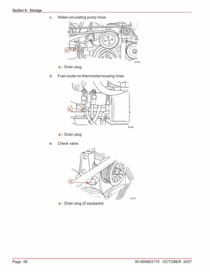
c. Water‑circulating pump hose
a
6143
a - Drain plug
d. Fuel‑cooler‑to‑thermostat‑housing hose
a
6144
a - Drain plug
e. Check valve
a
6131
a - Drain plug (if equipped)
Section 6 - Storage
90-899883179 OCTOBER 2007 Page 99
3. On models with a seawater pickup pump, remove the two blue drain plugs. If theseawater pickup pump does not have blue drain plugs, or you are unable to accessthem, loosen the clamps and remove both hoses.
6145
b
a
a - Hose clamps b - Blue drain plugs
4. Crank the engine over slightly with the starter motor to purge any water trapped in theseawater pickup pump. Do not allow the engine to start.
5. After the cooling system has been drained completely, install the drain plugs, reconnectthe hoses, and tighten all hose clamps securely.
BOAT IN THE WATER1. Close the seacock (if equipped) or remove and plug the water inlet hose.2. Remove the blue drain plugs from the following locations. If necessary, clean out the
drain holes using a stiff piece of wire. Do so until the entire system is drained.a. Port and starboard side of cylinder blockb. Bottom of exhaust manifolds
10226 M110050
93235672
b
aa
b
6129
a - Cylinder block drain plug b - Exhaust manifold drain plug
Section 6 - Storage
Page 100 90-899883179 OCTOBER 2007
c. Water‑circulating pump hose
a
6143
a - Drain plug
d. Fuel‑cooler‑to‑thermostat‑housing hose
a
6144
a - Drain plug
e. Check valve
a
6131
a - Drain plug (if equipped)
Section 6 - Storage
90-899883179 OCTOBER 2007 Page 101
3. On models with a seawater pickup pump, remove the two blue drain plugs. If theseawater pickup pump does not have blue drain plugs, or you are unable to accessthem, loosen the clamps and remove both hoses.
6145
b
a
a - Hose clamps b - Blue drain plugs
4. Crank the engine over slightly with the starter motor to purge any water trapped in theseawater pickup pump. Do not allow the engine to start.
5. Before launching the boat or starting the engine, close the drain system by installingthe blue drain plugs.
6. Open the seacock, if equipped, or unplug and reconnect the water inlet hose beforeoperating the engine.
Draining the SterndriveNOTE: This procedure is needed only for salty, brackish, mineral laden, or polluted waterapplications; and for freezing temperatures or extended storage.1. Insert a small wire repeatedly to make sure that vent holes, water drain holes, and
passages are unobstructed and open.
b
a
d
e
fc
6146
Sterndrive Water Drain Holesa - Speedometer pitot tubeb - Trim tab cavity vent holec - Trim tab cavity drain passage
d - Gear housing water drain hole (oneeach at port and starboard)
NOTICEThe universal joint bellows may develop a set when stored in a raised or up position,causing the bellows to fail when returned to service and allowing water to enter the boat.Store the sterndrive in the full down position.
2. Lower the sterndrive to the full down/in position.3. For additional assurance against freezing and rust, after draining, fill the cooling system
with propylene glycol mixed to the manufacturer's recommendation to protect theengine to the lowest temperature to which it will be exposed during freezingtemperatures or extended storage
Battery StorageWhenever the battery will be stored for an extended period of time, be sure the cells arefull of water and the battery is fully charged and in good operating condition. It should beclean and free of leaks. Follow the battery manufacturer's instructions for storage.
Power Package Recommissioning1. Ensure that all cooling system hoses are connected properly and hose clamps are tight.
! CAUTIONDisconnecting or connecting the battery cables in the incorrect order can cause injuryfrom electrical shock or can damage the electrical system. Always disconnect thenegative (‑) battery cable first and connect it last.
2. Install a fully charged battery. Clean the battery cable clamps and terminals andreconnect cables. Tighten each cable clamp securely when connecting.
3. Coat the terminal connections with a battery terminal anti‑corrosion agent.4. Perform all the checks in the before starting column of the Operation Chart.
NOTICEWithout sufficient cooling water, the engine, the water pump, and other components willoverheat and suffer damage. Provide a sufficient supply of water to the water inlets duringoperation.
5. Start the engine and closely observe instrumentation to ensure that all systems arefunctioning correctly.
6. Carefully inspect the engine for fuel, oil, fluid, water and exhaust leaks.7. Inspect the steering system, shift and throttle control for proper operation.